US5772332A - Container having a rectangular base and its manufacturing - Google Patents
Container having a rectangular base and its manufacturingDownload PDFInfo
- Publication number
- US5772332A US5772332AUS08/666,279US66627996AUS5772332AUS 5772332 AUS5772332 AUS 5772332AUS 66627996 AUS66627996 AUS 66627996AUS 5772332 AUS5772332 AUS 5772332A
- Authority
- US
- United States
- Prior art keywords
- sheet
- container
- edges
- base
- lateral edges
- Prior art date
- Legal status (The legal status is an assumption and is not a legal conclusion. Google has not performed a legal analysis and makes no representation as to the accuracy of the status listed.)
- Expired - Fee Related
Links
Images


Classifications
- B—PERFORMING OPERATIONS; TRANSPORTING
- B65—CONVEYING; PACKING; STORING; HANDLING THIN OR FILAMENTARY MATERIAL
- B65D—CONTAINERS FOR STORAGE OR TRANSPORT OF ARTICLES OR MATERIALS, e.g. BAGS, BARRELS, BOTTLES, BOXES, CANS, CARTONS, CRATES, DRUMS, JARS, TANKS, HOPPERS, FORWARDING CONTAINERS; ACCESSORIES, CLOSURES, OR FITTINGS THEREFOR; PACKAGING ELEMENTS; PACKAGES
- B65D75/00—Packages comprising articles or materials partially or wholly enclosed in strips, sheets, blanks, tubes or webs of flexible sheet material, e.g. in folded wrappers
- B65D75/52—Details
- B65D75/58—Opening or contents-removing devices added or incorporated during package manufacture
- B65D75/5861—Spouts
- B65D75/5872—Non-integral spouts
- B65D75/5883—Non-integral spouts connected to the package at the sealed junction of two package walls
- B—PERFORMING OPERATIONS; TRANSPORTING
- B29—WORKING OF PLASTICS; WORKING OF SUBSTANCES IN A PLASTIC STATE IN GENERAL
- B29C—SHAPING OR JOINING OF PLASTICS; SHAPING OF MATERIAL IN A PLASTIC STATE, NOT OTHERWISE PROVIDED FOR; AFTER-TREATMENT OF THE SHAPED PRODUCTS, e.g. REPAIRING
- B29C65/00—Joining or sealing of preformed parts, e.g. welding of plastics materials; Apparatus therefor
- B29C65/02—Joining or sealing of preformed parts, e.g. welding of plastics materials; Apparatus therefor by heating, with or without pressure
- B29C65/18—Joining or sealing of preformed parts, e.g. welding of plastics materials; Apparatus therefor by heating, with or without pressure using heated tools
- B—PERFORMING OPERATIONS; TRANSPORTING
- B29—WORKING OF PLASTICS; WORKING OF SUBSTANCES IN A PLASTIC STATE IN GENERAL
- B29C—SHAPING OR JOINING OF PLASTICS; SHAPING OF MATERIAL IN A PLASTIC STATE, NOT OTHERWISE PROVIDED FOR; AFTER-TREATMENT OF THE SHAPED PRODUCTS, e.g. REPAIRING
- B29C66/00—General aspects of processes or apparatus for joining preformed parts
- B29C66/01—General aspects dealing with the joint area or with the area to be joined
- B29C66/05—Particular design of joint configurations
- B29C66/10—Particular design of joint configurations particular design of the joint cross-sections
- B29C66/11—Joint cross-sections comprising a single joint-segment, i.e. one of the parts to be joined comprising a single joint-segment in the joint cross-section
- B29C66/112—Single lapped joints
- B29C66/1122—Single lap to lap joints, i.e. overlap joints
- B—PERFORMING OPERATIONS; TRANSPORTING
- B29—WORKING OF PLASTICS; WORKING OF SUBSTANCES IN A PLASTIC STATE IN GENERAL
- B29C—SHAPING OR JOINING OF PLASTICS; SHAPING OF MATERIAL IN A PLASTIC STATE, NOT OTHERWISE PROVIDED FOR; AFTER-TREATMENT OF THE SHAPED PRODUCTS, e.g. REPAIRING
- B29C66/00—General aspects of processes or apparatus for joining preformed parts
- B29C66/40—General aspects of joining substantially flat articles, e.g. plates, sheets or web-like materials; Making flat seams in tubular or hollow articles; Joining single elements to substantially flat surfaces
- B29C66/41—Joining substantially flat articles ; Making flat seams in tubular or hollow articles
- B29C66/43—Joining a relatively small portion of the surface of said articles
- B29C66/431—Joining the articles to themselves
- B—PERFORMING OPERATIONS; TRANSPORTING
- B29—WORKING OF PLASTICS; WORKING OF SUBSTANCES IN A PLASTIC STATE IN GENERAL
- B29C—SHAPING OR JOINING OF PLASTICS; SHAPING OF MATERIAL IN A PLASTIC STATE, NOT OTHERWISE PROVIDED FOR; AFTER-TREATMENT OF THE SHAPED PRODUCTS, e.g. REPAIRING
- B29C66/00—General aspects of processes or apparatus for joining preformed parts
- B29C66/50—General aspects of joining tubular articles; General aspects of joining long products, i.e. bars or profiled elements; General aspects of joining single elements to tubular articles, hollow articles or bars; General aspects of joining several hollow-preforms to form hollow or tubular articles
- B29C66/63—Internally supporting the article during joining
- B—PERFORMING OPERATIONS; TRANSPORTING
- B29—WORKING OF PLASTICS; WORKING OF SUBSTANCES IN A PLASTIC STATE IN GENERAL
- B29C—SHAPING OR JOINING OF PLASTICS; SHAPING OF MATERIAL IN A PLASTIC STATE, NOT OTHERWISE PROVIDED FOR; AFTER-TREATMENT OF THE SHAPED PRODUCTS, e.g. REPAIRING
- B29C66/00—General aspects of processes or apparatus for joining preformed parts
- B29C66/80—General aspects of machine operations or constructions and parts thereof
- B29C66/83—General aspects of machine operations or constructions and parts thereof characterised by the movement of the joining or pressing tools
- B29C66/832—Reciprocating joining or pressing tools
- B29C66/8322—Joining or pressing tools reciprocating along one axis
- B29C66/83221—Joining or pressing tools reciprocating along one axis cooperating reciprocating tools, each tool reciprocating along one axis
- B—PERFORMING OPERATIONS; TRANSPORTING
- B29—WORKING OF PLASTICS; WORKING OF SUBSTANCES IN A PLASTIC STATE IN GENERAL
- B29C—SHAPING OR JOINING OF PLASTICS; SHAPING OF MATERIAL IN A PLASTIC STATE, NOT OTHERWISE PROVIDED FOR; AFTER-TREATMENT OF THE SHAPED PRODUCTS, e.g. REPAIRING
- B29C66/00—General aspects of processes or apparatus for joining preformed parts
- B29C66/80—General aspects of machine operations or constructions and parts thereof
- B29C66/83—General aspects of machine operations or constructions and parts thereof characterised by the movement of the joining or pressing tools
- B29C66/834—General aspects of machine operations or constructions and parts thereof characterised by the movement of the joining or pressing tools moving with the parts to be joined
- B29C66/8341—Roller, cylinder or drum types; Band or belt types; Ball types
- B29C66/83411—Roller, cylinder or drum types
- B29C66/83413—Roller, cylinder or drum types cooperating rollers, cylinders or drums
- B—PERFORMING OPERATIONS; TRANSPORTING
- B29—WORKING OF PLASTICS; WORKING OF SUBSTANCES IN A PLASTIC STATE IN GENERAL
- B29C—SHAPING OR JOINING OF PLASTICS; SHAPING OF MATERIAL IN A PLASTIC STATE, NOT OTHERWISE PROVIDED FOR; AFTER-TREATMENT OF THE SHAPED PRODUCTS, e.g. REPAIRING
- B29C66/00—General aspects of processes or apparatus for joining preformed parts
- B29C66/80—General aspects of machine operations or constructions and parts thereof
- B29C66/83—General aspects of machine operations or constructions and parts thereof characterised by the movement of the joining or pressing tools
- B29C66/834—General aspects of machine operations or constructions and parts thereof characterised by the movement of the joining or pressing tools moving with the parts to be joined
- B29C66/8351—Jaws mounted on rollers, cylinders, drums, bands, belts or chains; Flying jaws
- B29C66/83511—Jaws mounted on rollers, cylinders, drums, bands, belts or chains; Flying jaws jaws mounted on rollers, cylinders or drums
- B29C66/83513—Jaws mounted on rollers, cylinders, drums, bands, belts or chains; Flying jaws jaws mounted on rollers, cylinders or drums cooperating jaws mounted on rollers, cylinders or drums and moving in a closed path
- B—PERFORMING OPERATIONS; TRANSPORTING
- B65—CONVEYING; PACKING; STORING; HANDLING THIN OR FILAMENTARY MATERIAL
- B65D—CONTAINERS FOR STORAGE OR TRANSPORT OF ARTICLES OR MATERIALS, e.g. BAGS, BARRELS, BOTTLES, BOXES, CANS, CARTONS, CRATES, DRUMS, JARS, TANKS, HOPPERS, FORWARDING CONTAINERS; ACCESSORIES, CLOSURES, OR FITTINGS THEREFOR; PACKAGING ELEMENTS; PACKAGES
- B65D33/00—Details of, or accessories for, sacks or bags
- B65D33/02—Local reinforcements or stiffening inserts, e.g. wires, strings, strips or frames
- B—PERFORMING OPERATIONS; TRANSPORTING
- B65—CONVEYING; PACKING; STORING; HANDLING THIN OR FILAMENTARY MATERIAL
- B65D—CONTAINERS FOR STORAGE OR TRANSPORT OF ARTICLES OR MATERIALS, e.g. BAGS, BARRELS, BOTTLES, BOXES, CANS, CARTONS, CRATES, DRUMS, JARS, TANKS, HOPPERS, FORWARDING CONTAINERS; ACCESSORIES, CLOSURES, OR FITTINGS THEREFOR; PACKAGING ELEMENTS; PACKAGES
- B65D75/00—Packages comprising articles or materials partially or wholly enclosed in strips, sheets, blanks, tubes or webs of flexible sheet material, e.g. in folded wrappers
- B65D75/008—Standing pouches, i.e. "Standbeutel"
- B—PERFORMING OPERATIONS; TRANSPORTING
- B29—WORKING OF PLASTICS; WORKING OF SUBSTANCES IN A PLASTIC STATE IN GENERAL
- B29C—SHAPING OR JOINING OF PLASTICS; SHAPING OF MATERIAL IN A PLASTIC STATE, NOT OTHERWISE PROVIDED FOR; AFTER-TREATMENT OF THE SHAPED PRODUCTS, e.g. REPAIRING
- B29C66/00—General aspects of processes or apparatus for joining preformed parts
- B29C66/40—General aspects of joining substantially flat articles, e.g. plates, sheets or web-like materials; Making flat seams in tubular or hollow articles; Joining single elements to substantially flat surfaces
- B29C66/41—Joining substantially flat articles ; Making flat seams in tubular or hollow articles
- B29C66/43—Joining a relatively small portion of the surface of said articles
- B29C66/431—Joining the articles to themselves
- B29C66/4312—Joining the articles to themselves for making flat seams in tubular or hollow articles, e.g. transversal seams
- B29C66/43121—Closing the ends of tubular or hollow single articles, e.g. closing the ends of bags
- B29C66/43122—Closing the top of gable top containers
- B—PERFORMING OPERATIONS; TRANSPORTING
- B29—WORKING OF PLASTICS; WORKING OF SUBSTANCES IN A PLASTIC STATE IN GENERAL
- B29C—SHAPING OR JOINING OF PLASTICS; SHAPING OF MATERIAL IN A PLASTIC STATE, NOT OTHERWISE PROVIDED FOR; AFTER-TREATMENT OF THE SHAPED PRODUCTS, e.g. REPAIRING
- B29C66/00—General aspects of processes or apparatus for joining preformed parts
- B29C66/70—General aspects of processes or apparatus for joining preformed parts characterised by the composition, physical properties or the structure of the material of the parts to be joined; Joining with non-plastics material
- B29C66/71—General aspects of processes or apparatus for joining preformed parts characterised by the composition, physical properties or the structure of the material of the parts to be joined; Joining with non-plastics material characterised by the composition of the plastics material of the parts to be joined
- B—PERFORMING OPERATIONS; TRANSPORTING
- B29—WORKING OF PLASTICS; WORKING OF SUBSTANCES IN A PLASTIC STATE IN GENERAL
- B29C—SHAPING OR JOINING OF PLASTICS; SHAPING OF MATERIAL IN A PLASTIC STATE, NOT OTHERWISE PROVIDED FOR; AFTER-TREATMENT OF THE SHAPED PRODUCTS, e.g. REPAIRING
- B29C66/00—General aspects of processes or apparatus for joining preformed parts
- B29C66/70—General aspects of processes or apparatus for joining preformed parts characterised by the composition, physical properties or the structure of the material of the parts to be joined; Joining with non-plastics material
- B29C66/72—General aspects of processes or apparatus for joining preformed parts characterised by the composition, physical properties or the structure of the material of the parts to be joined; Joining with non-plastics material characterised by the structure of the material of the parts to be joined
- B29C66/723—General aspects of processes or apparatus for joining preformed parts characterised by the composition, physical properties or the structure of the material of the parts to be joined; Joining with non-plastics material characterised by the structure of the material of the parts to be joined being multi-layered
- B—PERFORMING OPERATIONS; TRANSPORTING
- B29—WORKING OF PLASTICS; WORKING OF SUBSTANCES IN A PLASTIC STATE IN GENERAL
- B29K—INDEXING SCHEME ASSOCIATED WITH SUBCLASSES B29B, B29C OR B29D, RELATING TO MOULDING MATERIALS OR TO MATERIALS FOR MOULDS, REINFORCEMENTS, FILLERS OR PREFORMED PARTS, e.g. INSERTS
- B29K2077/00—Use of PA, i.e. polyamides, e.g. polyesteramides or derivatives thereof, as moulding material
- B—PERFORMING OPERATIONS; TRANSPORTING
- B31—MAKING ARTICLES OF PAPER, CARDBOARD OR MATERIAL WORKED IN A MANNER ANALOGOUS TO PAPER; WORKING PAPER, CARDBOARD OR MATERIAL WORKED IN A MANNER ANALOGOUS TO PAPER
- B31B—MAKING CONTAINERS OF PAPER, CARDBOARD OR MATERIAL WORKED IN A MANNER ANALOGOUS TO PAPER
- B31B2155/00—Flexible containers made from webs
- B—PERFORMING OPERATIONS; TRANSPORTING
- B31—MAKING ARTICLES OF PAPER, CARDBOARD OR MATERIAL WORKED IN A MANNER ANALOGOUS TO PAPER; WORKING PAPER, CARDBOARD OR MATERIAL WORKED IN A MANNER ANALOGOUS TO PAPER
- B31B—MAKING CONTAINERS OF PAPER, CARDBOARD OR MATERIAL WORKED IN A MANNER ANALOGOUS TO PAPER
- B31B2160/00—Shape of flexible containers
- B31B2160/20—Shape of flexible containers with structural provision for thickness of contents
- B—PERFORMING OPERATIONS; TRANSPORTING
- B31—MAKING ARTICLES OF PAPER, CARDBOARD OR MATERIAL WORKED IN A MANNER ANALOGOUS TO PAPER; WORKING PAPER, CARDBOARD OR MATERIAL WORKED IN A MANNER ANALOGOUS TO PAPER
- B31B—MAKING CONTAINERS OF PAPER, CARDBOARD OR MATERIAL WORKED IN A MANNER ANALOGOUS TO PAPER
- B31B2170/00—Construction of flexible containers
- B31B2170/20—Construction of flexible containers having multi-layered walls, e.g. laminated or lined
- B—PERFORMING OPERATIONS; TRANSPORTING
- B31—MAKING ARTICLES OF PAPER, CARDBOARD OR MATERIAL WORKED IN A MANNER ANALOGOUS TO PAPER; WORKING PAPER, CARDBOARD OR MATERIAL WORKED IN A MANNER ANALOGOUS TO PAPER
- B31B—MAKING CONTAINERS OF PAPER, CARDBOARD OR MATERIAL WORKED IN A MANNER ANALOGOUS TO PAPER
- B31B50/00—Making rigid or semi-rigid containers, e.g. boxes or cartons
- B31B50/14—Cutting, e.g. perforating, punching, slitting or trimming
- B31B50/16—Cutting webs
- B31B50/18—Cutting webs longitudinally
- B—PERFORMING OPERATIONS; TRANSPORTING
- B31—MAKING ARTICLES OF PAPER, CARDBOARD OR MATERIAL WORKED IN A MANNER ANALOGOUS TO PAPER; WORKING PAPER, CARDBOARD OR MATERIAL WORKED IN A MANNER ANALOGOUS TO PAPER
- B31B—MAKING CONTAINERS OF PAPER, CARDBOARD OR MATERIAL WORKED IN A MANNER ANALOGOUS TO PAPER
- B31B70/00—Making flexible containers, e.g. envelopes or bags
- B31B70/74—Auxiliary operations
- B31B70/81—Forming or attaching accessories, e.g. opening devices, closures or tear strings
Definitions
- the present inventionis related to a container having a rectangular base and it concerns also a method for manufacturing same.
- containerit is referred to a container manufactured of sheets or films of flexible material formed into a suitable shape useful for containing unitary items, powdered or granulated material or liquids.
- Containers with which the present invention is concernedare a practical and cheap way for packing goods and are thus very common in the food industry although not restricted to that field.
- the major advantages of containersare that they are easy to manufacture, cheap and are usually suitable for holding a variety of products. Such containers require minimal space in storage and are easily disposed of.
- the most used form of containeris the so-called "pouch” which is a sheet of material, e.g. paper, cardboard, plastic or a laminate formed into the shape of a bag or sack.
- pouchesare integrally formed with a base.
- such pouchesare not self-standing and they require the internal pressure of their contents for stability.
- such pouchesare usually oval and are thus less stable and also require more storage space.
- Still another drawbackis that the structure of such products is not firm and thus they may collapse when they are not completely full.
- heat weldable materialor "heat weldable surface” are used for determining layers of plastic material, e.g. polyethylene, polypropylene, etc. which, upon heating melt and may then be adhered to other such layers by a process which hereinafter in the specification will be referred to as "welding".
- weldinga process which hereinafter in the specification will be referred to as "welding”.
- heat weldableis also referred to in the art as “heat sealable”.
- Typical containersare made of a single sheet folded into a container's shape with overlapping portions which are then glued or welded to one another. Such containers are usually not suitable for containing liquids and do not have a rigid structure whereby they collapse when their contents are partially withdrawn. Furthermore, containers manufactured according to the heretofore known methods are usually restricted to pouch or prismatic box-like containers.
- a containermade essentially of one or more film sheets, the container having a bottom base and walls extending upwardly therefrom; the base being essentially rectangular and defining front, rear and two side sections of the walls; the base being made of a film with both of its faces being heat weldable and the walls being made of a film having at least an inner heat weldable face; the container being constructed from a pouch having a front, rear and bottom sheet; the bottom sheet of the pouch being folded along a midline thereof with flaps extending downwards from the fold line and each of the two bottom edges of the flaps being welded to or integral with one bottom edge of either the front or the rear sheet, lateral edges of the front and rear sheet being welded to one another with the two bottom portions of the welded edges sandwiching both lateral edges of the bottom folded sheet; for construction of the container, a central portion of the bottom sheet is unfolded such that the unfolded portion has an essentially rectangular shape thus forming said base, with central parts of the bottom edges of the bottom sheet
- the bottom base and the wallsare produced of an integral film sheet having both faces thereof heat weldable.
- one or more reinforcement elements made of or coated with a heat weldable materialis welded to the bottom face of the rectangular base and welded thereto.
- the reinforcement elementmay be constructed of several segments or may be a uniform frame, welded to the inner face of the walls adjacent their top or bottom edges.
- a reinforcement element welded to the topmay have a shape and size corresponding to that of the rectangular base whereby a rectangular box-like container is obtained.
- the reinforcement elementmay be of any other shape or size. If the reinforcement element is a rectangle larger than the base then a truncated square pyramid is acquired, suitable for stacking such containers within one another.
- stiff elongate ribsmade of or coated with a heat weldable material are welded along the internal walls of the container so as to impart rigidity thereto.
- the stiff ribsare formed integrally with one or more reinforcing elements. Said stiff ribs may have different shapes so that when they are welded to the walls the container obtains a shape corresponding to that of said ribs.
- the present inventionfurther provides a process for the manufacture of a container, the container having an essentially rectangular base with walls, consisting of a front, rear and two side sections extending upwardly therefrom, the base being made of a film with both of its faces being heat weldable and the walls being made of a film having at least an inner heat weldable face; the process comprises:
- Another aspect of the present inventionconcerns continuous processes for preparing pouches useful in continuous manufacture of containers according to the invention.
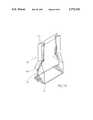
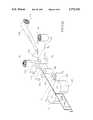
- FIG. 1is an exploded isometric view of the constituents of a basic container according to the present invention positioned according to a first step of its manufacture;
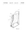
- FIG. 2is an isometric view of a pouch manufactured according to the present invention
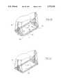
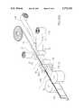
- FIG. 3illustrates how the rectangular shape of the base is obtained
- FIG. 4is a schematic illustration of the welding process of the rectangular base
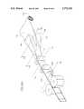
- FIG. 5is an isometric view of a basic form of a container according to the present invention.
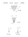
- FIG. 6is an exploded isometric view of only a bottom portion of a container according to the present invention and a reinforcement element;
- FIG. 7is a schematic illustration of how the reinforcement frame of FIG. 6 is welded to the rectangular base of the container;
- FIG. 8is an isometric view of a container according to the present invention in which the top edges of the front and rear walls are welded so as to seal the container;
- FIG. 9is an isometric view of a container according to the present invention in which the top edges of the side walls are welded so as to seal the container;
- FIG. 10is a side elevation of the container of FIG. 9;
- FIG. 11is an exploded isometric view of only a top portion of a container according to the present invention and a reinforcement frame;
- FIG. 12is an isometric view of a container according to the present invention having a shape of an inverted truncated rectangular pyramid;
- FIG. 13is an exploded isometric view of only a top portion of a container according to the present invention with a rectangular reinforcement frame provided with integral elongate studs projecting downwards;
- FIG. 14is an exploded isometric view of only a top portion of a container according to the present invention with a rectangular reinforcement frame provided with a box-like support structure;
- FIG. 15is an isometric view of a container according to the present invention in which the top base is smaller than the rectangular base;
- FIG. 16is an isometric view of a container according to the present invention formed with a narrowing middle portion
- FIGS. 17(a)-(d)are isometric exploded views of different means for sealing or closing the top of the container;
- FIG. 18is an isometric view of another embodiment of a container according to the present invention.
- FIG. 19is an isometric view illustrating a modification of a container according to the present invention.
- FIG. 20is an isometric partial view of a step in obtaining a base according to a modification of the invention.
- FIG. 21is an isometric partial view of the modification as in FIG. 20;
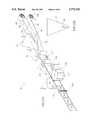
- FIG. 22is a perspective view depicting a continuous manufacturer process of a container in accordance with an embodiment of the present invention.
- FIG. 23(a)is a perspective view depicting one process for preparing a pouch for the manufacture of a container according to the present invention
- FIGS. 23(b)-(g)are schematic cross-sections through different stages of the process of FIG. 23(a);
- FIG. 24(a)is a second process for preparing a pouch for the manufacture of a container according to the present invention.
- FIGS. 24(b)-(d)are schematic cross-sections through different stages of the process of FIG. 24(a);
- FIG. 25(a)is a perspective view depicting the manufacture of a pouch according to a third process for the manufacture of a container according to the present invention.
- FIGS. 25(b)-(d)are schematic cross-sections through different stages of the process of FIG. 25(a);
- FIG. 26(a)is a perspective view depicting the manufacture of a pouch according to still a different process, for the manufacture of a container according to the present invention.
- FIGS. 26(b)-(e)are schematic cross-sections through different stages of the process of FIG. 26(a).
- FIGS. 1 and 2 of the drawingsin which two sheets 1 and 2 of substantially the same size are positioned facing each other where the facing surfaces of the sheets are made of or coated with a heat weldable material such as polyethylene.
- a third sheet 3has the same width as that of sheets 1 and 2 and is made of or coated on both faces with a heat weldable material.
- the third sheet 3is folded into two and is then placed between the two sheets with its bottom edges 4 aligned with the bottom edges 5 of sheets 1 and 2 and the fold line 7 between the sheets 1 and 2.
- a single sheet of material made of or coated on both faces thereof with a heat sealable materialis used instead of said three single sheets 1, 2 and 3 as can readily be understood and illustrated in FIG. 1 by the dashed lines.
- a second stepthe bottom edges 5 of sheets 1 and 2 are welded to respective bottom edges 4 of sheet 3. Welding of the two bottom edges 4 to one another is prevented by first inserting therebetween a plate 9 coated with a non adhering material such as TeflonTM or silicon, prior to the welding process. At the end of this process a pouch generally designated 11 is formed.
- a non adhering materialsuch as TeflonTM or silicon
- FIGS. 3-5illustrating how the rectangular base is formed.
- a rectangular core member 15is provided with members 16 and 17 laterally expendable in two perpendicular axes and coated with a non adhering material. The core 15 is then inserted into the pouch 11 and is pushed down until a central portion of the third sheet 3 becomes substantially flat at the bottom of the pouch 11 whereby, a flat rectangular base 20 is formed.
- side walls 18are formed as well as two overlapping triangular portions 19 formed out of the third sheet 3 at each side of the container and which partially overlap the side walls 18.
- the elements 16 and 17 of the core member 15are then expanded as seen in FIG. 4 so as to snugly fit at the bottom of the pouch, pressing the triangular portions 19 against the side walls 18.
- the triangular portions 19In order to fix the rectangular shape of the base, the triangular portions 19 must be welded to the side walls 18. Heat is applied to the triangular portions by electric thermal pads 21 as known per se and if required also from thermal elements within core 15 (not shown). After the expandable members 16 and 17 are retracted, the core 15 can be removed from the pouch and a self-standing rectangular base container according to the present invention is obtained.
- a reinforcement element 22is made of or coated with a heat sealable material and which in the particular embodiment has a rectangular frame shape fitted for welding to the bottom surface of the rectangular base 20 in a manner as will hereinafter be explained in detail.
- the reinforcement memberhas an inverted L-shaped cross-section for supporting a peripheral portion of the base.
- itmay be provided with strengthening ribs or may be a flat surface or even consists of four individual right angled members.
- FIG. 7schematically illustrates how the reinforcement element 22 is attached to the container's base.
- a first expandable rectangular core 15 as explained with reference to FIG. 4is inserted into the container and a second similar expandable rectangular core member 15' is positioned under the reinforcement element 22. Then the cores 15 and 15' are expanded and pushed against one another whereby the reinforcement member is brought into position with respect to the container, with heat applied by electric thermal pads 21, whereby the reinforcement element is welded to the container as already explained. Heat may also be emitted by heat pads integral with the core members 15 and 15'.
- FIG. 8illustrates one embodiment of sealing the container by welding the top edges of the front and rear walls 1 and 2. In this way the container maintains its rectangular base shape.
- FIGS. 9 and 10show how the container is sealed by welding the top edges of the side walls 18 obtaining the special shape as seen.
- the dashed line 19illustrates a tear-line for pouring liquid.
- FIG. 11there is shown a top rectangular portion of a container 11 and a rectangular reinforcement frame element 25.
- the reinforcement frame 25is made of or coated with a heat weldable material and when assembled it snugly fits within the container flush with the top edges and is then welded thereto, whereby the top edge of the container acquires the shape of the reinforcing element and becomes firm and will not deform.
- reinforcement element 25any size and shape of reinforcement element 25 may be used as long as it can be securely welded to the top edges of the container. It should also be obvious that the reinforcement element made be made of or coated with a heat sealable material as previously explained, or it may be made of metal or other suitable material which may be secured to the container by folding it over the top edges of the container and clampingly attaching it or by other means as known per se.
- a container 11is formed as already explained with the sheets 1 and 2 made of a material which may be stretched under heat such as polyamide and which sheets are coated or laminated with a heat weldable material. Then, an expandable core having a cross-section of a rectangular pyramid (not shown) is fully inserted into the container and is expanded until its side plates are pressed against the inner walls of the container. Then the expanded core is heated by internal thermal elements (not shown) to a temperature suitable for plastic deformation of the laminate constituting the walls of the container. It is then slowly drawn out of the container while gradually expanding the cross-section of the core, resulting in that the container acquires a shape of an inverted truncated rectangular pyramid as seen in FIG. 12.
- the rectangular pyramid-shapemay be formed in a hot environment instead of applying direct heat to the container, for example, in an oven or in a hot air tunnel or in a combination thereof.
- the container seen in FIG. 12is suitable for stacking within similar such containers, thereby reducing storage space required for such empty containers.
- FIG. 13illustrates how a reinforcement element 27, made of or coated with a heat sealable material, is integral with four reinforcement studs 28 projecting downwards from the corners of the frame.
- the studs 28are also made of or coated with a heat sealable material and are substantially as long as the inner length of the container.
- the frame 27 with the integral studs 28is inserted into the container 11 and is welded to the container by applying heat and pressure thereto by means of an expandable core (not shown), as already explained.
- a second reinforcement frame 30is integral at an opposed end of the studs 28 parallelly disposed with respect to the top reinforcement frame 27, whereby improved rigidity is obtained.
- FIG. 14differs from FIG. 13 in that instead of the four studs 28 the reinforcement element 27 is integral with a reinforcement box-like structure made of or coated with a heat sealable material and suitable for inserting into the container 11 abutting with the walls of the container.
- the reinforcement box-like structure 29is welded to the walls of the container but this is not compulsory.
- FIG. 15 of the drawingsillustrates a container with narrowing walls.
- the straight edges 29(illustrated by dashed lines) are reformed along a concave line 31 which may as well be straight or other lines.
- the edgesare welded along lines 31 by means of hot pressure plates (not shown) obtaining the narrowing shape of the container.
- reinforcement frame 32is welded at the top of the container as previously explained and the excessive welded flaps 33 may be cut adjacent the welding line 31 for pleasing the eye.
- FIG. 16shows a container with a narrowing portion 36 along the container, whereby new corner edge 37 is produced by pinching and welding together respective portions of the side walls with the adjacent front and rear walls, similar to the embodiment of FIG. 15 and if required removing the excessive portions 36.
- FIG. 17illustrates several means for sealing or closing the top of the container.
- a frame 41 made of or coated with a heat sealable materialis provided with a nozzle 42 which frame 41 is welded or attached to frame 25 as previously discussed.
- the contents of the containeris consumed through nozzle 42 which may be closed by a suitable seal.
- FIG. 17(b)there is an aluminum foil 43 embedded within a frame 44 made of or coated with a heat sealable material which snugly fits within frame 45.
- the frame 44is welded to frame 45, whereby the container is sealed.
- the aluminum foil 43is cut adjacent frame 44 and removed whereby a suitable plastic cover may be provided for repeatable sealing and closing of the container.
- the containeris sealed by cover 46 provided with a nozzle 47, whereby the cover 46 is directly welded or otherwise attached to the container 11 omitting the use of a reinforcement frame 45.
- a foil 48 made of aluminum or any other material suitable for sealing and having an integral frame 49is directly welded to the top edges of container 11, omitting the use of frame 45 as in FIG. 17(c). It should be obvious that the cover may be attached to the container by any other suitable means as known per se.
- FIG. 18another embodiment of a container is seen in which the side walls 18' consist of a substantially flat portion 51 and a gusset portion 52 consisting of two overlapping flaps 53 and an intermediate portion 54.
- FIG. 19shows how the container is manufactured in the shape of a jug formed with a handle portion 56 and a pouring mouth 57.
- the handle portionis made by forming a gusset portion as in the embodiment of FIG. 18 and welding the overlapping flaps 53' to one another. Thereafter, an opening 58 is cut out in each of the flaps 53', said openings serving for gripping the container.
- FIGS. 20 and 21illustrate the steps of reinforcing the base portion of the container according to another embodiment of the invention.
- a slot 60is cut at each corner of the base skirt 61.
- the portions of the skirtare folded inward as indicated by arrows 62 and are welded to the bottom face of the base member 20, whereby the base becomes stiff and durable.
- FIGS. 22 to 26schematically depicting the stages of a process for manufacturing a container according to the present invention, comprising also filling and sealing mains.
- FIGS. 1 to 5Various manufacturing stages and components of the container are the same as those of FIGS. 1 to 5 and accordingly, like elements and components are given the same reference numerals as the corresponding ones in FIGS. 1 to 5 with a prime indication, and the reader is referred to those previous figures for a detailed explanation.
- FIG. 22depicts a schematic layout of a continuous process for preparing, filling and sealing a container according to the present invention.
- a first step generally designated 70is preparing a pouch 11'. Several detailed examples of this step will be specified hereinafter.
- the prepared pouch 11'then approaches a rotating work site generally designated 72 and comprising gripping means 74 which may be, for example, vacuum pads as known per se. Then, at 76 the pouch 11' is expanded by suction means separating the sheets 1' and 2' from one another.
- gripping means 74which may be, for example, vacuum pads as known per se.
- the next step indicated 78comprises inserting an expandable core 80 into the pouch and at station 82 a central portion of the bottom sheet of the pouch is unfolded so that the unfolded portion assumes its rectangular shape and the two peripheral portions form two overlapping triangular portions as explained. Finally, two welding pads 84 laterally approach the container and weld the two overlapping triangulares in order to fix the container's shape, as hereinbefore explained.
- working stationsmay be added to the assembly 72, e.g. for adding reinforcement elements, special configuration of the container, etc. as already explained hereinabove.
- the work site 72then discharges the container over a conveyer belt 86, advancing the ready container to a filling station 88 for automatically filling as known per se.
- the filled containersprogress over the conveyor belt towards a sealing site generally designated 90, wherein the containers are gripped by suitable arms 92 and introduced into a sealing station 94, wherein the containers are sealed, e.g. by welding the top edges as illustrated in FIG. 8 or by any other suitable sealing means as described with reference to FIGS. 9, 10 or 17 or otherwise.
- the containersare ready for consuming and are conveyed by conveyor 96 to a packing station (not shown).
- FIGS. 23(a) to (g)there is seen the first step of the process, generally designated 70 in which a pouch 11' is prepared.
- a first film 100having a top surface 102 coated with a heat weldable material, released from an unwinding roller 104.
- a second film 106having both faces thereof coated with a heat weldable material, is dispensed from an unwinding roller 108, centrally positioned over the first film 100 (as seen in FIG. 23(c)).
- the central portion of the filmis then sucked into a recess 109 at an edge of a triangular-shaped forming member 110 (better seen in FIGS. 23(b) and (e)).
- the films positioned by pulleys 112 and 114pass over a blade 116, whereby the films are cut along their bottom edge and the cross-section of the films now resemble that presented in FIG. 1 of the drawings.
- Two hot rollers 118are positioned juxtaposed one another with a non-adhering plate (e.g. TeflonTM or silicon) 120 positioned therebetween.
- a non-adhering platee.g. TeflonTM or silicon
- the filmstravel between the rollers 118, the bottom edges 4' and 5' of the sheets are welded and as the laminate passes between rollers 122 it is welded by the hot welding ribs 124, whereby a plurality of joined pouches 126 are produced, which are then separated at a cutting station 128 as can be understood.
- FIGS. 24(a) to (d)two sheets 130 and 132, having their facing faces coated with a heat weldable material, are dispensed from unwinding rollers 134 and 136, respectively.
- the third film 138is folded in two by a grooved triangular member 142 as explained with reference to FIG. 23(b).
- the folded sheet 138 (forming the base sheet) and sheets 130 and 132 (forming the walls)then progress via positioning pulleys 144 and 146 and their bottom edges are welded by welding rollers 148, with an un-weldable plate 150 introduced therebetween as already explained.
- the laminateis welded by welding ribs 152 of rollers 154 whereby the side edges of the pouches are formed. Finally the pouches 126' are separated from one another as explained hereinabove.
- FIGS. 25(a) to (d)illustrate a process essentially similar to that of FIGS. 24(a) to (d), with the exception that a reclosable zipper-like strap 136 is welded to the top edges of the pouch by welding rollers 158 and a nonwelding plate 160 introduced between the sheets.
- the pouches and containers later prepared by this processcan thus be closed and opened many times as can be appreciated.
- FIGS. 26(a) to (e)illustrate how a pouch useful in preparing a container according to the present invention may be prepared from a single sheet 162 having both faces heat weldable and released from an unwinding roller 164.
- the film sheet 162travels between a block member 166 having an essentially W-like cross-section and between a triangular cross-shaped gliding member 168, gradually forming the film to a shape as seen in FIGS. 26(b) and (c), so that when the film reaches the positioning pulleys 170 it has already obtained the configuration illustrated in FIG. 1 (with the dashed line). From here on the process continues as already explained with reference to FIGS. 23 to 25.
Landscapes
- Engineering & Computer Science (AREA)
- Mechanical Engineering (AREA)
- Bag Frames (AREA)
Abstract
Description
The present invention is related to a container having a rectangular base and it concerns also a method for manufacturing same. By using the term "container" it is referred to a container manufactured of sheets or films of flexible material formed into a suitable shape useful for containing unitary items, powdered or granulated material or liquids.
Containers with which the present invention is concerned are a practical and cheap way for packing goods and are thus very common in the food industry although not restricted to that field. The major advantages of containers are that they are easy to manufacture, cheap and are usually suitable for holding a variety of products. Such containers require minimal space in storage and are easily disposed of.
The most used form of container is the so-called "pouch" which is a sheet of material, e.g. paper, cardboard, plastic or a laminate formed into the shape of a bag or sack.
In some cases pouches are integrally formed with a base. However, such pouches are not self-standing and they require the internal pressure of their contents for stability. Furthermore, such pouches are usually oval and are thus less stable and also require more storage space. Still another drawback is that the structure of such products is not firm and thus they may collapse when they are not completely full.
In the present description and claims, the terms "heat weldable material" or "heat weldable surface" are used for determining layers of plastic material, e.g. polyethylene, polypropylene, etc. which, upon heating melt and may then be adhered to other such layers by a process which hereinafter in the specification will be referred to as "welding". The term "heat weldable" is also referred to in the art as "heat sealable".
Typical containers are made of a single sheet folded into a container's shape with overlapping portions which are then glued or welded to one another. Such containers are usually not suitable for containing liquids and do not have a rigid structure whereby they collapse when their contents are partially withdrawn. Furthermore, containers manufactured according to the heretofore known methods are usually restricted to pouch or prismatic box-like containers.
It is an object of the present invention to provide a novel and improved container and a process for manufacturing, same in which the above-referred to disadvantages are substantially reduced or overcome.
According to the present invention there is provided a container made essentially of one or more film sheets, the container having a bottom base and walls extending upwardly therefrom; the base being essentially rectangular and defining front, rear and two side sections of the walls; the base being made of a film with both of its faces being heat weldable and the walls being made of a film having at least an inner heat weldable face; the container being constructed from a pouch having a front, rear and bottom sheet; the bottom sheet of the pouch being folded along a midline thereof with flaps extending downwards from the fold line and each of the two bottom edges of the flaps being welded to or integral with one bottom edge of either the front or the rear sheet, lateral edges of the front and rear sheet being welded to one another with the two bottom portions of the welded edges sandwiching both lateral edges of the bottom folded sheet; for construction of the container, a central portion of the bottom sheet is unfolded such that the unfolded portion has an essentially rectangular shape thus forming said base, with central parts of the bottom edges of the bottom sheet forming the front and rear edges of the base and with peripheral portions of the bottom sheet forming two overlapping triangular portions with the bottom edges thereof defining the two side edges of the rectangular base, thereby forming the container's front and rear wall sections extending from said front and rear edges and side walls extending from said side edges with the welded edges of the two sheets being at about the midline of the side walls; the structure being fixed by welding the two overlapping triangular portions to one another or by welding a peripheral triangular portion of the two overlapping ones to a juxtaposed inner face of the side sheets.
According to one embodiment of the present invention the bottom base and the walls are produced of an integral film sheet having both faces thereof heat weldable.
In order to impart the container according to the present invention rigidity, one or more reinforcement elements made of or coated with a heat weldable material is welded to the bottom face of the rectangular base and welded thereto. The reinforcement element may be constructed of several segments or may be a uniform frame, welded to the inner face of the walls adjacent their top or bottom edges.
A reinforcement element welded to the top may have a shape and size corresponding to that of the rectangular base whereby a rectangular box-like container is obtained. Alternatively, the reinforcement element may be of any other shape or size. If the reinforcement element is a rectangle larger than the base then a truncated square pyramid is acquired, suitable for stacking such containers within one another.
According to still another embodiment of the present invention, stiff elongate ribs made of or coated with a heat weldable material are welded along the internal walls of the container so as to impart rigidity thereto. Alternatively, the stiff ribs are formed integrally with one or more reinforcing elements. Said stiff ribs may have different shapes so that when they are welded to the walls the container obtains a shape corresponding to that of said ribs.
The present invention further provides a process for the manufacture of a container, the container having an essentially rectangular base with walls, consisting of a front, rear and two side sections extending upwardly therefrom, the base being made of a film with both of its faces being heat weldable and the walls being made of a film having at least an inner heat weldable face; the process comprises:
(a) preparing a pouch having a front, rear and bottom sheet, the bottom sheet being folded along a midline thereof with the flaps extending downwards from the fold line and the two bottom edges of the flaps being each welded to or integral with a bottom edge of either the front or the rear sheet, lateral edges of the front and rear sheet being welded to one another with their bottom portions sandwiching both lateral edges of the bottom sheet;
(b) unfolding a central portion of the bottom sheet such that the unfolded portion assumes a rectangular shape and the two peripheral portions form two overlapping triangular portions;
(c) welding the two overlapping triangular portions to one another or welding a peripheral triangular portion of the two with juxtaposed inner face of a juxtaposed sheet.
Another aspect of the present invention concerns continuous processes for preparing pouches useful in continuous manufacture of containers according to the invention.
For better understanding, the invention will now be described by way of example only, with reference to the accompanying drawings, in which:
FIG. 1 is an exploded isometric view of the constituents of a basic container according to the present invention positioned according to a first step of its manufacture;
FIG. 2 is an isometric view of a pouch manufactured according to the present invention;
FIG. 3 illustrates how the rectangular shape of the base is obtained;
FIG. 4 is a schematic illustration of the welding process of the rectangular base;
FIG. 5 is an isometric view of a basic form of a container according to the present invention;
FIG. 6 is an exploded isometric view of only a bottom portion of a container according to the present invention and a reinforcement element;
FIG. 7 is a schematic illustration of how the reinforcement frame of FIG. 6 is welded to the rectangular base of the container;
FIG. 8 is an isometric view of a container according to the present invention in which the top edges of the front and rear walls are welded so as to seal the container;
FIG. 9 is an isometric view of a container according to the present invention in which the top edges of the side walls are welded so as to seal the container;
FIG. 10 is a side elevation of the container of FIG. 9;
FIG. 11 is an exploded isometric view of only a top portion of a container according to the present invention and a reinforcement frame;
FIG. 12 is an isometric view of a container according to the present invention having a shape of an inverted truncated rectangular pyramid;
FIG. 13 is an exploded isometric view of only a top portion of a container according to the present invention with a rectangular reinforcement frame provided with integral elongate studs projecting downwards;
FIG. 14 is an exploded isometric view of only a top portion of a container according to the present invention with a rectangular reinforcement frame provided with a box-like support structure;
FIG. 15 is an isometric view of a container according to the present invention in which the top base is smaller than the rectangular base;
FIG. 16 is an isometric view of a container according to the present invention formed with a narrowing middle portion;
FIGS. 17(a)-(d) are isometric exploded views of different means for sealing or closing the top of the container;
FIG. 18 is an isometric view of another embodiment of a container according to the present invention;
FIG. 19 is an isometric view illustrating a modification of a container according to the present invention;
FIG. 20 is an isometric partial view of a step in obtaining a base according to a modification of the invention;
FIG. 21 is an isometric partial view of the modification as in FIG. 20;
FIG. 22 is a perspective view depicting a continuous manufacturer process of a container in accordance with an embodiment of the present invention;
FIG. 23(a) is a perspective view depicting one process for preparing a pouch for the manufacture of a container according to the present invention;
FIGS. 23(b)-(g) are schematic cross-sections through different stages of the process of FIG. 23(a);
FIG. 24(a) is a second process for preparing a pouch for the manufacture of a container according to the present invention;
FIGS. 24(b)-(d) are schematic cross-sections through different stages of the process of FIG. 24(a);
FIG. 25(a) is a perspective view depicting the manufacture of a pouch according to a third process for the manufacture of a container according to the present invention;
FIGS. 25(b)-(d) are schematic cross-sections through different stages of the process of FIG. 25(a);
FIG. 26(a) is a perspective view depicting the manufacture of a pouch according to still a different process, for the manufacture of a container according to the present invention; and
FIGS. 26(b)-(e) are schematic cross-sections through different stages of the process of FIG. 26(a).
Reference is first made to FIGS. 1 and 2 of the drawings in which twosheets
Athird sheet 3 has the same width as that ofsheets third sheet 3 is folded into two and is then placed between the two sheets with itsbottom edges 4 aligned with thebottom edges 5 ofsheets fold line 7 between thesheets
Alternatively, a single sheet of material made of or coated on both faces thereof with a heat sealable material is used instead of said threesingle sheets
Then thelateral edges 6 of thesheets lateral edges 8 at the foldedsheet 3.
At a second step thebottom edges 5 ofsheets bottom edges 4 ofsheet 3. Welding of the twobottom edges 4 to one another is prevented by first inserting therebetween aplate 9 coated with a non adhering material such as Teflon™ or silicon, prior to the welding process. At the end of this process a pouch generally designated 11 is formed.
Reference is now being made to FIGS. 3-5 illustrating how the rectangular base is formed. Arectangular core member 15 is provided withmembers core 15 is then inserted into thepouch 11 and is pushed down until a central portion of thethird sheet 3 becomes substantially flat at the bottom of thepouch 11 whereby, a flatrectangular base 20 is formed.
As seen in FIG. 5, after this step is completed,side walls 18 are formed as well as two overlappingtriangular portions 19 formed out of thethird sheet 3 at each side of the container and which partially overlap theside walls 18. Theelements core member 15 are then expanded as seen in FIG. 4 so as to snugly fit at the bottom of the pouch, pressing thetriangular portions 19 against theside walls 18.
In order to fix the rectangular shape of the base, thetriangular portions 19 must be welded to theside walls 18. Heat is applied to the triangular portions by electricthermal pads 21 as known per se and if required also from thermal elements within core 15 (not shown). After theexpandable members
In accordance with another embodiment shown in FIG. 6, areinforcement element 22 is made of or coated with a heat sealable material and which in the particular embodiment has a rectangular frame shape fitted for welding to the bottom surface of therectangular base 20 in a manner as will hereinafter be explained in detail. As seen, the reinforcement member has an inverted L-shaped cross-section for supporting a peripheral portion of the base. Alternatively it may be provided with strengthening ribs or may be a flat surface or even consists of four individual right angled members.
FIG. 7 schematically illustrates how thereinforcement element 22 is attached to the container's base. A first expandablerectangular core 15 as explained with reference to FIG. 4 is inserted into the container and a second similar expandable rectangular core member 15' is positioned under thereinforcement element 22. Then thecores 15 and 15' are expanded and pushed against one another whereby the reinforcement member is brought into position with respect to the container, with heat applied by electricthermal pads 21, whereby the reinforcement element is welded to the container as already explained. Heat may also be emitted by heat pads integral with thecore members 15 and 15'.
FIG. 8 illustrates one embodiment of sealing the container by welding the top edges of the front andrear walls
FIGS. 9 and 10 show how the container is sealed by welding the top edges of theside walls 18 obtaining the special shape as seen. The dashedline 19 illustrates a tear-line for pouring liquid.
Referring now to FIG. 11 there is shown a top rectangular portion of acontainer 11 and a rectangularreinforcement frame element 25. Thereinforcement frame 25 is made of or coated with a heat weldable material and when assembled it snugly fits within the container flush with the top edges and is then welded thereto, whereby the top edge of the container acquires the shape of the reinforcing element and becomes firm and will not deform.
However, it should be obvious that any size and shape ofreinforcement element 25 may be used as long as it can be securely welded to the top edges of the container. It should also be obvious that the reinforcement element made be made of or coated with a heat sealable material as previously explained, or it may be made of metal or other suitable material which may be secured to the container by folding it over the top edges of the container and clampingly attaching it or by other means as known per se.
In FIG. 12 acontainer 11 is formed as already explained with thesheets
Alternatively the rectangular pyramid-shape may be formed in a hot environment instead of applying direct heat to the container, for example, in an oven or in a hot air tunnel or in a combination thereof.
Then a rectangular reinforcement frame element 25' having a larger projection than therectangular base 20 is welded to the top edge of the container as seen in FIG. 12, imparting the container's rigidity.
The container seen in FIG. 12 is suitable for stacking within similar such containers, thereby reducing storage space required for such empty containers.
FIG. 13 illustrates how areinforcement element 27, made of or coated with a heat sealable material, is integral with fourreinforcement studs 28 projecting downwards from the corners of the frame. Thestuds 28 are also made of or coated with a heat sealable material and are substantially as long as the inner length of the container. Theframe 27 with theintegral studs 28 is inserted into thecontainer 11 and is welded to the container by applying heat and pressure thereto by means of an expandable core (not shown), as already explained.
In accordance with another embodiment of the present invention, also seen in FIG. 13, asecond reinforcement frame 30 is integral at an opposed end of thestuds 28 parallelly disposed with respect to thetop reinforcement frame 27, whereby improved rigidity is obtained.
Once thestuds 28 are welded to the container, the latter becomes reinforced in its axial direction too, retaining its rectangular box-like shape even if it is crashed while empty.
FIG. 14 differs from FIG. 13 in that instead of the fourstuds 28 thereinforcement element 27 is integral with a reinforcement box-like structure made of or coated with a heat sealable material and suitable for inserting into thecontainer 11 abutting with the walls of the container. Preferably the reinforcement box-like structure 29 is welded to the walls of the container but this is not compulsory.
FIG. 15 of the drawings illustrates a container with narrowing walls. After forming thecontainer 11 as already explained, the straight edges 29 (illustrated by dashed lines) are reformed along aconcave line 31 which may as well be straight or other lines. The edges are welded alonglines 31 by means of hot pressure plates (not shown) obtaining the narrowing shape of the container. Thenreinforcement frame 32 is welded at the top of the container as previously explained and the excessive welded flaps 33 may be cut adjacent thewelding line 31 for pleasing the eye.
FIG. 16 shows a container with a narrowingportion 36 along the container, wherebynew corner edge 37 is produced by pinching and welding together respective portions of the side walls with the adjacent front and rear walls, similar to the embodiment of FIG. 15 and if required removing theexcessive portions 36.
FIG. 17 illustrates several means for sealing or closing the top of the container. In FIG. 17(a) aframe 41 made of or coated with a heat sealable material is provided with anozzle 42 whichframe 41 is welded or attached to frame 25 as previously discussed. The contents of the container is consumed throughnozzle 42 which may be closed by a suitable seal. In FIG. 17(b) there is analuminum foil 43 embedded within aframe 44 made of or coated with a heat sealable material which snugly fits withinframe 45. Theframe 44 is welded to frame 45, whereby the container is sealed. When it is desired to consume the contents of the container, then thealuminum foil 43 is cutadjacent frame 44 and removed whereby a suitable plastic cover may be provided for repeatable sealing and closing of the container.
In FIG. 17(c) the container is sealed bycover 46 provided with anozzle 47, whereby thecover 46 is directly welded or otherwise attached to thecontainer 11 omitting the use of areinforcement frame 45.
In FIG. 17(d) afoil 48 made of aluminum or any other material suitable for sealing and having anintegral frame 49 is directly welded to the top edges ofcontainer 11, omitting the use offrame 45 as in FIG. 17(c). It should be obvious that the cover may be attached to the container by any other suitable means as known per se.
In FIG. 18 another embodiment of a container is seen in which the side walls 18' consist of a substantiallyflat portion 51 and agusset portion 52 consisting of two overlappingflaps 53 and anintermediate portion 54.
FIG. 19 shows how the container is manufactured in the shape of a jug formed with ahandle portion 56 and a pouringmouth 57. The handle portion is made by forming a gusset portion as in the embodiment of FIG. 18 and welding the overlapping flaps 53' to one another. Thereafter, anopening 58 is cut out in each of the flaps 53', said openings serving for gripping the container.
FIGS. 20 and 21 illustrate the steps of reinforcing the base portion of the container according to another embodiment of the invention. After the container is complete as seen in FIG. 5, instead of attaching a reinforcement member 22 (as in FIG. 6), aslot 60 is cut at each corner of thebase skirt 61. Then, the portions of the skirt are folded inward as indicated byarrows 62 and are welded to the bottom face of thebase member 20, whereby the base becomes stiff and durable.
Attention is now directed to FIGS. 22 to 26 schematically depicting the stages of a process for manufacturing a container according to the present invention, comprising also filling and sealing mains.
Various manufacturing stages and components of the container are the same as those of FIGS. 1 to 5 and accordingly, like elements and components are given the same reference numerals as the corresponding ones in FIGS. 1 to 5 with a prime indication, and the reader is referred to those previous figures for a detailed explanation.
FIG. 22 depicts a schematic layout of a continuous process for preparing, filling and sealing a container according to the present invention.
A first step generally designated 70 is preparing a pouch 11'. Several detailed examples of this step will be specified hereinafter.
The prepared pouch 11' then approaches a rotating work site generally designated 72 and comprising gripping means 74 which may be, for example, vacuum pads as known per se. Then, at 76 the pouch 11' is expanded by suction means separating the sheets 1' and 2' from one another.
The next step indicated 78 comprises inserting anexpandable core 80 into the pouch and at station 82 a central portion of the bottom sheet of the pouch is unfolded so that the unfolded portion assumes its rectangular shape and the two peripheral portions form two overlapping triangular portions as explained. Finally, twowelding pads 84 laterally approach the container and weld the two overlapping triangulares in order to fix the container's shape, as hereinbefore explained.
Further, working stations may be added to theassembly 72, e.g. for adding reinforcement elements, special configuration of the container, etc. as already explained hereinabove. Thework site 72 then discharges the container over aconveyer belt 86, advancing the ready container to a fillingstation 88 for automatically filling as known per se.
Then, the filled containers progress over the conveyor belt towards a sealing site generally designated 90, wherein the containers are gripped bysuitable arms 92 and introduced into a sealingstation 94, wherein the containers are sealed, e.g. by welding the top edges as illustrated in FIG. 8 or by any other suitable sealing means as described with reference to FIGS. 9, 10 or 17 or otherwise.
At the end of this step, the containers are ready for consuming and are conveyed byconveyor 96 to a packing station (not shown).
Referring now to FIGS. 23(a) to (g), there is seen the first step of the process, generally designated 70 in which a pouch 11' is prepared.
Afirst film 100, having atop surface 102 coated with a heat weldable material, released from an unwindingroller 104. Simultaneously, asecond film 106, having both faces thereof coated with a heat weldable material, is dispensed from an unwindingroller 108, centrally positioned over the first film 100 (as seen in FIG. 23(c)).
The central portion of the film is then sucked into arecess 109 at an edge of a triangular-shaped forming member 110 (better seen in FIGS. 23(b) and (e)).
The films positioned bypulleys blade 116, whereby the films are cut along their bottom edge and the cross-section of the films now resemble that presented in FIG. 1 of the drawings.
Twohot rollers 118 are positioned juxtaposed one another with a non-adhering plate (e.g. Teflon™ or silicon) 120 positioned therebetween. As the films travel between therollers 118, the bottom edges 4' and 5' of the sheets are welded and as the laminate passes betweenrollers 122 it is welded by thehot welding ribs 124, whereby a plurality of joinedpouches 126 are produced, which are then separated at a cuttingstation 128 as can be understood.
In FIGS. 24(a) to (d), twosheets rollers third sheet 138, having both faces heat weldable, is dispensed from unwindingroller 140.
Before approaching the facingfilms third film 138 is folded in two by a groovedtriangular member 142 as explained with reference to FIG. 23(b). The folded sheet 138 (forming the base sheet) andsheets 130 and 132 (forming the walls) then progress via positioningpulleys rollers 148, with anun-weldable plate 150 introduced therebetween as already explained.
Then the laminate is welded by weldingribs 152 ofrollers 154 whereby the side edges of the pouches are formed. Finally the pouches 126' are separated from one another as explained hereinabove.
FIGS. 25(a) to (d) illustrate a process essentially similar to that of FIGS. 24(a) to (d), with the exception that a reclosable zipper-like strap 136 is welded to the top edges of the pouch by weldingrollers 158 and anonwelding plate 160 introduced between the sheets. The pouches and containers later prepared by this process can thus be closed and opened many times as can be appreciated.
FIGS. 26(a) to (e) illustrate how a pouch useful in preparing a container according to the present invention may be prepared from asingle sheet 162 having both faces heat weldable and released from an unwindingroller 164. Thefilm sheet 162 travels between ablock member 166 having an essentially W-like cross-section and between a triangularcross-shaped gliding member 168, gradually forming the film to a shape as seen in FIGS. 26(b) and (c), so that when the film reaches the positioning pulleys 170 it has already obtained the configuration illustrated in FIG. 1 (with the dashed line). From here on the process continues as already explained with reference to FIGS. 23 to 25.
It should be obvious to a person versed in the art that any combination of the above embodiments may be carried out mutatis mutandis.
Claims (6)
1. A container having a base with a front edge, a rear edge and side edges, and walls extending upwardly therefrom; the base being generally rectangular and being made of a film having an inner face and an outer face, said inner and outer faces being heat weldable, and the walls being made of a film having an inner face and an outer face, with at least said inner face being heat weldable; said base and said walls of the container being constructed from a front sheet having a bottom edge, a top edge and lateral edges, a rear sheet having a bottom edge, a top edge and lateral edges, and a bottom sheet; the bottom sheet being foldable along a midline thereof with first and second flaps extending downwards from the midline, said flaps each having a bottom edge and lateral edges, and wherein the bottom edge of the first flap is joined to the bottom edge of the front sheet and the bottom edge of the second flap is joined to the bottom edge of the rear sheet; wherein the lateral edges of the front sheet and the rear sheet are welded to one another with bottom portions of the lateral edges of the front and rear sheets sandwiching lateral edges of the first and second flaps; wherein the bottom sheet is unfoldable into a substantially rectangular shape to form said base, with central parts of the bottom edges of the flaps of the bottom sheet forming the front and rear edges of the base and with peripheral portions of the bottom sheet forming two overlapping triangular portions having lower edges thereof defining the side edges of the base, and side walls extending from said side edges of said base with the welded lateral edges of the front and rear sheets being at about a midline of the side walls; said container being fixed by welding the two overlapping triangular portions; and stiff elongated studs composed at least in part of a heat weldable material, said studs being welded to the walls of the container and projecting from a reinforcement element welded to a region of said container, said region being selected from the group consisting of a top of said container or a bottom of said container, and wherein the studs extend substantially an entire length of the container.
2. A container having a base with a front edge, a rear edge and side edges, and walls extending upwardly therefrom; the base being generally rectangular and being made of a film having an inner face and an outer face, said inner and outer faces being heat weldable, and the walls being made of a film having an inner face and an outer face, with at least said inner face being heat weldable; said base and said walls of the container being constructed from a front sheet having a bottom edge, a top edge and lateral edges, a rear sheet having a bottom edge, a top edge and lateral edges, and a bottom sheet; the bottom sheet being foldable along a midline thereof with first and second flaps extending downwards from the midline, said flaps each having a bottom edge and lateral edges, and wherein the bottom edge of the first flap is joined to the bottom edge of the front sheet and the bottom edge of the second flap is joined to the bottom edge of the rear sheet; wherein the lateral edges of the front sheet and the rear sheet are welded to one another with bottom portions of the lateral edges of the front and rear sheets sandwiching lateral edges of the first and second flaps; wherein the bottom sheet is unfoldable into a substantially rectangular shape to form said base, with central parts of the bottom edges of the flaps of the bottom sheet forming the front and rear edges of the base and with peripheral portions of the bottom sheet forming two overlapping triangular portions having lower edges thereof defining the side edges of the base, and side walls extending from said side edges of said base with the welded lateral edges of the front and rear sheets being at about a midline of the side walls; said container being fixed by welding the two overlapping triangular portions; and stiff elongated studs composed at least in part of a heat weldable material, said studs being welded to the walls of the container, and wherein the elongated studs each have a form defined by one or more curves, and wherein the walls of the container acquire a shape defined by the studs.
3. A container having a base with a front edge, a rear edge and side edges, and walls extending upwardly therefrom; the base being generally rectangular and being made of a film having an inner face and an outer face, said inner and outer faces being heat weldable, and the walls being made of a film having an inner face and an outer face, with at least said inner face being heat weldable; said base and said walls of the container being constructed from a front sheet having a bottom edge, a top edge and lateral edges, a rear sheet having a bottom edge, a top edge and lateral edges, and a bottom sheet; the bottom sheet being foldable along a midline thereof with first and second flaps extending downwards from the midline, said flaps each having a bottom edge and lateral edges, and wherein the bottom edge of the first flap is joined to the bottom edge of the front sheet and the bottom edge of the second flap is joined to the bottom edge of the rear sheet; wherein the lateral edges of the front sheet and the rear sheet are welded to one another with bottom portions of the lateral edges of the front and rear sheets sandwiching lateral edges of the first and second flaps; wherein the bottom sheet is unfoldable into a substantially rectangular shape to form said base, with central parts of the bottom edges of the flaps of the bottom sheet forming the front and rear edges of the base and with peripheral portions of the bottom sheet forming two overlapping triangular portions having lower edges thereof defining the side edges of the base, and side walls extending from said side edges of said base with the welded lateral edges of the front and rear sheets being at about a midline of the side walls; said container being fixed by welding the two overlapping triangular portions; and a reinforcement box-like stiff structure welded within the container.
4. A container having a base with a front edge, a rear edge and side edges, and walls extending upwardly therefrom; the base being generally rectangular and being made of a film having an inner face and an outer face, said inner and outer faces being heat weldable, and the walls being made of a film having an inner face and an outer face, with at least said inner face being heat weldable; said base and said walls of the container being constructed from a front sheet having a bottom edge, a top edge and lateral edges, a rear sheet having a bottom edge, a top edge and lateral edges, and a bottom sheet; the bottom sheet being foldable along a midline thereof with first and second flaps extending downwards from the midline, said flaps each having a bottom edge and lateral edges, and wherein the bottom edge of the first flap is joined to the bottom edge of the front sheet and the bottom edge of the second flap is joined to the bottom edge of the rear sheet; wherein the lateral edges of the front sheet and the rear sheet are welded to one another with bottom portions of the lateral edges of the front and rear sheets sandwiching lateral edges of the first and second flaps; wherein the bottom sheet is unfoldable into a substantially rectangular shape to form said base, with central parts of the bottom edges of the flaps of the bottom sheet forming the front and rear edges of the base and with peripheral portions of the bottom sheet forming two overlapping triangular portions having lower edges thereof defining the side edges of the base, and side walls extending from said side edges of said base with the welded lateral edges of the front and rear sheets being at about a midline of the side walls; said container being fixed by welding the two overlapping triangular portions; and a skirt extending around said bottom sheet forming said base, said skirt being formed by the welding of said container, and wherein said skirt is folded over a bottom face of the bottom sheet and welded thereto.
5. A process for the manufacture of a container, the container having a generally rectangular base and walls extending therefrom, the base being made of a film having an inner face and an outer face, with both of said faces being heat weldable, and the walls being made of a film having an inner face and an outer face, with at least said inner face of said film forming said walls being heat weldable, the process comprising:
(a) constructing said container from a front sheet having a bottom edge and lateral edges, a rear sheet having a bottom edge and lateral edges, and a bottom sheet, the bottom sheet being folded along a midline thereof with first and second flaps extending downwards from the midline, said flaps each having a bottom edge and lateral edges, and wherein the bottom edge of the first flap is joined to the bottom edge of the front sheet and the bottom edge of the second flap is joined to the bottom edge of the rear sheet; and welding lateral edges of the front and rear sheet to one another with bottom portions of the lateral edges of the front and rear sheets sandwiching lateral edges of the first and second flaps;
(b) unfolding the bottom sheet such that a central portion of the sheet assumes a rectangular shape and two peripheral portions of the sheet form two overlapping triangular portions:
(c) welding the two overlapping triangular portions to one another or welding a peripheral triangular portion of the two with juxtaposed inner face of a juxtaposed sheet; and
(d) welding a reinforcement box-like stiff structure within the container.
6. A process for the manufacture of a container, the container having a generally rectangular base and walls extending therefrom, the base being made of a film having an inner face and an outer face, with both of said faces being heat weldable, and the walls being made of a film having an inner face and an outer face, with at least said inner face of said film forming said walls being heat weldable, the process comprising:
(a) constructing said container from a front sheet having a bottom edge and lateral edges, a rear sheet having a bottom edge and lateral edges, and a bottom sheet, the bottom sheet being folded along a midline thereof with first and second flaps extending downwards from the midline, said flaps each having a bottom edge and lateral edges, and wherein the bottom edge of the first flap is joined to the bottom edge of the front sheet and the bottom edge of the second flap is joined to the bottom edge of the rear sheet; and welding lateral edges of the front and rear sheet to one another with bottom portions of the lateral edges of the front and rear sheets sandwiching lateral edges of the first and second flaps;
(b) unfolding the bottom sheet such that the a central portion of the sheet assumes a rectangular shape and two peripheral portions of the sheet form two overlapping triangular portions:
(c) welding the two overlapping triangular portions to one another or welding a peripheral triangular portion of the two with juxtaposed inner face of a juxtaposed sheet; and
(d) folding a skirt formed by the welding of said container over a bottom face of the bottom sheet and welding the folded skirt to said bottom face of said bottom sheet.
Priority Applications (1)
| Application Number | Priority Date | Filing Date | Title |
|---|---|---|---|
| US08/666,279US5772332A (en) | 1994-09-30 | 1995-10-02 | Container having a rectangular base and its manufacturing |
Applications Claiming Priority (4)
| Application Number | Priority Date | Filing Date | Title |
|---|---|---|---|
| IL11111494AIL111114A0 (en) | 1994-09-30 | 1994-09-30 | Package having a rectangular base and its manufacture |
| IL111114 | 1994-09-30 | ||
| PCT/US1995/012264WO1996010524A2 (en) | 1994-09-30 | 1995-10-02 | Container having a rectangular base and its manufacturing |
| US08/666,279US5772332A (en) | 1994-09-30 | 1995-10-02 | Container having a rectangular base and its manufacturing |
Related Child Applications (1)
| Application Number | Title | Priority Date | Filing Date |
|---|---|---|---|
| US09/030,807ContinuationUS6231237B1 (en) | 1994-09-30 | 1998-02-26 | Container having rectangular base and its manufacturing |
Publications (1)
| Publication Number | Publication Date |
|---|---|
| US5772332Atrue US5772332A (en) | 1998-06-30 |
Family
ID=26322912
Family Applications (1)
| Application Number | Title | Priority Date | Filing Date |
|---|---|---|---|
| US08/666,279Expired - Fee RelatedUS5772332A (en) | 1994-09-30 | 1995-10-02 | Container having a rectangular base and its manufacturing |
Country Status (1)
| Country | Link |
|---|---|
| US (1) | US5772332A (en) |
Cited By (73)
| Publication number | Priority date | Publication date | Assignee | Title |
|---|---|---|---|---|
| WO1999008862A1 (en)* | 1997-08-19 | 1999-02-25 | Technical Developers, Inc. | Container and method of manufacturing same from a web of flexible material |
| US6036365A (en)* | 1996-03-21 | 2000-03-14 | Imer; Rodney Haydn | Rectangular thin film pack |
| US6095361A (en)* | 1999-06-07 | 2000-08-01 | Huang; Jammy | Case frame for a game machine |
| US6231237B1 (en)* | 1994-09-30 | 2001-05-15 | Atifon Ltd. | Container having rectangular base and its manufacturing |
| WO2001096194A1 (en)* | 2000-06-14 | 2001-12-20 | Atifon Ltd. | Plastic film pouch having a closable zipper |
| US20040131284A1 (en)* | 2002-09-19 | 2004-07-08 | Stolmeier Robert C. | Pouch with spout |
| US20050244084A1 (en)* | 2004-05-03 | 2005-11-03 | Tilman Paul A | Reclosable stand-up package and method of manufacturing same |
| US20070048421A1 (en)* | 2005-09-01 | 2007-03-01 | Cryovac, Inc. | Flexible package having insulating support member |
| US20070159293A1 (en)* | 2004-09-21 | 2007-07-12 | Microbridge Technologies Canada, Inc. | Compensating for linear and non-linear trimming-induced shift of temperature coefficient of resistance |
| US20070242905A1 (en)* | 2006-04-13 | 2007-10-18 | Weaver Rodney M | Gusseted pouch |
| US20080247681A1 (en)* | 2002-09-19 | 2008-10-09 | Stolmeier Robert C | Pouch with spout |
| US20090148077A1 (en)* | 2007-12-07 | 2009-06-11 | Claude Mauffette | Container for recyclable and other materials |
| US20100140129A1 (en)* | 2008-11-06 | 2010-06-10 | Clear Lam Packaging, Inc. | Flexible, Stackable Container and Method and System for Manufacturing Same |
| US20100284634A1 (en)* | 2009-05-11 | 2010-11-11 | Bob Hadley | Container insert apparatus and method |
| RU2412879C2 (en)* | 2009-01-11 | 2011-02-27 | Общество с ограниченной ответственностью "Актуаль" | Package from flexible polymer material |
| US20120298663A1 (en)* | 2011-05-26 | 2012-11-29 | Printpack Illinois, Inc. | Flexible sturdy base container and method for making the same |
| US20130139473A1 (en)* | 2011-12-05 | 2013-06-06 | Fres-Co System Usa, Inc. | Gusseted flexible package with shaped sides and methods of making the same |
| US20130248526A1 (en)* | 2012-03-20 | 2013-09-26 | Berry Plastics Corporation | Package |
| US8602244B2 (en) | 2007-08-08 | 2013-12-10 | Clear Lam Packaging, Inc. | Flexible, stackable sealed package having corner seals and formed from a sheet of film |
| USD715643S1 (en) | 2013-07-30 | 2014-10-21 | Clear Lam Packaging, Inc. | Package |
| US20150086138A1 (en)* | 2013-09-20 | 2015-03-26 | Pouch Pac Innovations, Llc | Flexible pouch with drip pad |
| US20150082748A1 (en)* | 2013-09-25 | 2015-03-26 | Neil Draper | Method of Making an Asphalt Container |
| USD725467S1 (en) | 2013-07-30 | 2015-03-31 | Clear Lam Packaging, Inc. | Package |
| USD726535S1 (en) | 2013-07-30 | 2015-04-14 | Clear Lam Packaging, Inc. | Package |
| WO2015074872A1 (en)* | 2013-11-22 | 2015-05-28 | Wacker Chemie Ag | Process for producing polycrystalline silicon |
| USD730725S1 (en) | 2014-03-07 | 2015-06-02 | Clear Lam Packaging, Inc. | Package |
| USD733549S1 (en) | 2013-10-25 | 2015-07-07 | Clear Lam Packaging, Inc. | Package |
| USD734144S1 (en) | 2014-05-30 | 2015-07-14 | Clear Lam Packaging, Inc. | Package |
| USD739232S1 (en) | 2013-07-30 | 2015-09-22 | Clear Lam Packaging, Inc. | Film used to make packages |
| USD740114S1 (en) | 2014-03-07 | 2015-10-06 | Clear Lam Packaging, Inc. | Package |
| US20150329257A1 (en)* | 2012-12-27 | 2015-11-19 | Sca Hygiene Products Ab | Package of a stack of flexible articles |
| USD746673S1 (en) | 2014-06-20 | 2016-01-05 | Clear Lam Packaging, Inc. | Package |
| USD747189S1 (en) | 2013-09-09 | 2016-01-12 | Clear Lam Packaging, Inc. | Package |
| USD747202S1 (en) | 2014-02-28 | 2016-01-12 | Clear Lam Packaging, Inc. | Film used to make packages |
| USD747195S1 (en) | 2014-02-14 | 2016-01-12 | Clear Lam Packaging, Inc. | Film for packaging production |
| USD747646S1 (en) | 2014-06-20 | 2016-01-19 | Clear Lam Packaging, Inc. | Package |
| USD748471S1 (en) | 2014-02-14 | 2016-02-02 | Clear Lam Packaging, Inc. | Film for packaging production |
| USD750477S1 (en) | 2014-03-07 | 2016-03-01 | Clear Lam Packaging, Inc. | Package |
| USD753996S1 (en) | 2014-03-26 | 2016-04-19 | Clear Lam Packaging, Inc. | Package |
| USD753995S1 (en) | 2014-03-07 | 2016-04-19 | Clear Lam Packaging, Inc. | Film for packaging production |
| USD754534S1 (en) | 2014-09-25 | 2016-04-26 | Clear Lam Packaging, Inc. | Package |
| USD756219S1 (en) | 2014-10-31 | 2016-05-17 | Clear Lam Packaging, Inc. | Package |
| USD761651S1 (en) | 2014-01-28 | 2016-07-19 | Clear Lam Packaging, Inc. | Package |
| USD764914S1 (en) | 2013-11-12 | 2016-08-30 | Clear Lam Packaging, Inc. | Package |
| USD766082S1 (en) | 2014-02-28 | 2016-09-13 | Clear Lam Packaging, Inc. | Package |
| USD768479S1 (en) | 2014-01-16 | 2016-10-11 | Clear Lam Packaging, Inc. | Package |
| USD772069S1 (en) | 2014-09-25 | 2016-11-22 | Clear Lam Packaging, Inc. | Film for making packages |
| EP3109179A1 (en)* | 2015-06-26 | 2016-12-28 | Trioplast Nyborg A/S | Welded bag |
| US20170008696A1 (en)* | 2014-01-24 | 2017-01-12 | Pöner Ingenieurgesellschaft Mbh | Transport bag |
| USD777026S1 (en) | 2013-11-12 | 2017-01-24 | Clear Lam Packaging, Inc. | Package |
| USD778719S1 (en) | 2014-10-15 | 2017-02-14 | Clear Lam Packaging, Inc. | Package |
| USD781702S1 (en) | 2014-08-25 | 2017-03-21 | Clear Lam Packaging, Inc. | Material for packaging production |
| USD782324S1 (en) | 2015-12-02 | 2017-03-28 | Poly-America, L.P. | Reclosable shopping bag |
| USD782918S1 (en) | 2015-12-02 | 2017-04-04 | Poly-America, L.P. | Reclosable shopping bag |
| USD783414S1 (en) | 2015-12-02 | 2017-04-11 | Poly-America, L.P. | Reclosable shopping bag |
| USD784127S1 (en) | 2014-10-31 | 2017-04-18 | Clear Lam Packaging, Inc. | Film for packaging production |
| USD784157S1 (en) | 2015-12-02 | 2017-04-18 | Poly-America, L.P. | Reclosable shopping bag |
| USD784824S1 (en) | 2015-12-09 | 2017-04-25 | Poly-America, L.P. | Reclosable shopping bag |
| USD787319S1 (en) | 2014-11-17 | 2017-05-23 | Clear Lam Packaging, Inc. | Package |
| USD788582S1 (en) | 2014-10-31 | 2017-06-06 | Clear Lam Packaging, Inc. | Film for packaging production |
| US9745104B2 (en) | 2012-10-26 | 2017-08-29 | Clear Lam Packaging, Inc. | Flexible stackable package |
| USD796342S1 (en) | 2015-12-09 | 2017-09-05 | Poly-America, L.P. | Reclosable shopping bag |
| US20180002092A1 (en)* | 2015-01-29 | 2018-01-04 | Coveris Flexibles France | Preformed bag made of flexible plastic material and methods for providing a preformed bag from a film made of flexible material with a rigid frame |
| EP2935032B1 (en)* | 2012-12-20 | 2018-02-21 | Nestec S.A. | Flexible pouch with a larger opening |
| USD813663S1 (en) | 2014-03-13 | 2018-03-27 | Primapak, Llc | Package |
| US20180244435A1 (en)* | 2015-09-28 | 2018-08-30 | Bemis Company, Inc. | Pouch with flexible self-sealing dispensing valve |
| US10207850B2 (en) | 2012-10-26 | 2019-02-19 | Primapak, Llc. | Flexible package and method of making same |
| US10322851B2 (en)* | 2016-12-14 | 2019-06-18 | Ah Moi TAN | Self-supporting plastic bag and method for manufacturing same |
| US10421584B2 (en) | 2015-12-02 | 2019-09-24 | Poly-America, L.P. | Reclosable bag and method to make same |
| US10532872B2 (en) | 2014-12-08 | 2020-01-14 | Berry Plastics Corporation | Package |
| US10843837B2 (en) | 2015-09-18 | 2020-11-24 | Primapak, Llc | Apparatus and method for making a flexible package |
| US10994882B2 (en) | 2014-05-19 | 2021-05-04 | Primapak, Llc | Apparatus and method for making a flexible package |
| US20210222103A1 (en)* | 2016-05-11 | 2021-07-22 | Corning Incorporated | Structured bag for cell culture |
Citations (44)
| Publication number | Priority date | Publication date | Assignee | Title |
|---|---|---|---|---|
| US1255133A (en)* | 1917-02-05 | 1918-02-05 | Paul H Carr | Collapsible drinking-cup. |
| DE348106C (en)* | 1918-05-04 | 1922-01-30 | Mathias Birken | Injection carburetor |
| US1648890A (en)* | 1926-05-14 | 1927-11-15 | Beasley Walter Joseph | Collapsible casing |
| US1671050A (en)* | 1924-05-09 | 1928-05-22 | Kaelma Mfg Company Inc | Method of making reenforced bags |
| AU237936A (en)* | 1936-06-13 | 1937-07-01 | Harvey Daniel | Improvements in roller conveyors for fruit andother articles |
| US2143957A (en)* | 1937-04-27 | 1939-01-17 | Noel A Petter | Display package |
| FR1077359A (en)* | 1953-05-16 | 1954-11-08 | Laroche Freres | Improvements to the conformation of plastic bags |
| US3136475A (en)* | 1961-01-16 | 1964-06-09 | Bemis Bro Bag Co | Bag bottom closure having a v-shaped bottom |
| US3172796A (en)* | 1959-09-25 | 1965-03-09 | Gulker Heinz | Method of forming conical-shaped containers of thermoplastic material |
| FR1431079A (en)* | 1965-01-29 | 1966-03-11 | Ethylene Plastique Sa | Collapsible containers and in particular cups and method for their manufacture |
| US3434652A (en)* | 1966-07-26 | 1969-03-25 | Diamond Shamrock Corp | Self-supporting plastic container and method of making same |
| US3462067A (en)* | 1968-07-25 | 1969-08-19 | Diamond Shamrock Corp | Self-supporting plastic container |
| JPS46588Y1 (en)* | 1967-11-14 | 1971-01-11 | ||
| US3554434A (en)* | 1968-11-08 | 1971-01-12 | Dave Chapman | Free-standing flexible package |
| US3739977A (en)* | 1971-06-22 | 1973-06-19 | J Shapiro | Plastic market bag |
| US3743172A (en)* | 1971-03-23 | 1973-07-03 | Mobil Oil Corp | Quilted laminar films comprising at least two layers of dissimilar material |
| DE2440491A1 (en)* | 1973-08-28 | 1975-03-06 | Dainippon Printing Co Ltd | SQUARE CONTAINER AND DEVICE FOR ITS MAKING |
| US3980225A (en)* | 1974-12-25 | 1976-09-14 | Dai Nippon Insatsu Kabushiki Kaisha | Self-standing bag |
| JPS51153508U (en)* | 1975-05-31 | 1976-12-07 | ||
| US4041851A (en)* | 1970-06-11 | 1977-08-16 | Jentsch Hans G | Method for making plastic bags |
| DE2652454A1 (en)* | 1976-11-17 | 1978-05-18 | Unilever Nv | Self standing folding bag - has joining points in corner parts for guiding unfolding of folded bottom |
| DE2801851A1 (en)* | 1977-01-17 | 1978-07-20 | Ucb Sa | BAG WITH HANDLE |
| JPS542320A (en)* | 1977-06-04 | 1979-01-09 | Idemitsu Kosan Co Ltd | Pesticide for viral blight of plant |
| JPS5744530A (en)* | 1980-08-29 | 1982-03-13 | Nissan Motor Co Ltd | Roof structure for vehicle |
| EP0052151A1 (en)* | 1980-11-13 | 1982-05-26 | Kessel, Christoph, Ing. grad | Ply-bottom bag and apparatus for making it |
| US4353497A (en)* | 1979-10-15 | 1982-10-12 | Mobil Oil Corporation | Free-standing thermoplastic bag construction |
| US4361235A (en)* | 1978-02-15 | 1982-11-30 | Societe Generale Des Eaux Minerales De Vittel | Containers made of thin pliable synthetic material, and process of manufacturing it |
| US4377192A (en)* | 1980-01-28 | 1983-03-22 | Societe Generale Des Eaux Minerales De Vittel | Pitcher-like vessel with reinforced handle |
| JPS62501969A (en)* | 1985-02-28 | 1987-08-06 | ソシエテ ジエネラル デ オウ ミネラル ド ヴイツテル | Bags made of flexible synthetic material and with reinforced stabilizers |
| US4718738A (en)* | 1986-11-14 | 1988-01-12 | Kapak Corp. | Flexible bank for coins |
| US4779998A (en)* | 1986-09-26 | 1988-10-25 | Rock-Tenn Company | Composite bag-like package |
| US4810109A (en)* | 1986-08-21 | 1989-03-07 | Jean Castel | Supple bag made by flat assembly of a system of films intended to constitute, by extension, a stable recipient, and process for obtaining same |
| US4848931A (en)* | 1985-11-20 | 1989-07-18 | Toyo Aluminium Kabushiki Kaisha | Packaging sheet and containers and pouches using the sheet |
| WO1989012006A1 (en)* | 1988-06-10 | 1989-12-14 | INDAG Gesellschaft für Industriebedarf mbH | Refillable bag |
| WO1990008704A2 (en)* | 1989-01-26 | 1990-08-09 | INDAG Gesellschaft für Industriebedarf mbH | Flat-ended bag |
| US4947525A (en)* | 1989-03-23 | 1990-08-14 | Zip-Pak Incorporated | Zipper closure with internal peel seal |
| US5059036A (en)* | 1990-04-27 | 1991-10-22 | Kapak Corporation | Vented pouch arrangement and method |
| US5073035A (en)* | 1991-05-09 | 1991-12-17 | Williams Kenneth J | Bulk carrying bag |
| EP0524487A1 (en)* | 1991-07-24 | 1993-01-27 | JOSEF W. OSTENDORF GmbH & CO. | Flexible package, filled with paint having a pasty consistency |
| JPH0577838A (en)* | 1991-05-31 | 1993-03-30 | Isao Hirata | Simple vessel substituted for bottle |
| US5205651A (en)* | 1988-09-26 | 1993-04-27 | Societe Generale Des Eaux Minerales De Vittel | Container made of synthetic material with improved rigidity |
| JPH06122456A (en)* | 1992-10-07 | 1994-05-06 | Dainippon Printing Co Ltd | Independent soft packaging bag |
| US5350240A (en)* | 1990-06-01 | 1994-09-27 | S. C. Johnson & Son, Inc. | Stand-up pouch having cross-seal feature and method of making |
| US5352043A (en)* | 1991-05-29 | 1994-10-04 | Sumitomo Bakelite Co., Limited | Self-supporting bag, a method of production thereof and an apparatus for production thereof |
- 1995
- 1995-10-02USUS08/666,279patent/US5772332A/ennot_activeExpired - Fee Related
Patent Citations (46)
| Publication number | Priority date | Publication date | Assignee | Title |
|---|---|---|---|---|
| US1255133A (en)* | 1917-02-05 | 1918-02-05 | Paul H Carr | Collapsible drinking-cup. |
| DE348106C (en)* | 1918-05-04 | 1922-01-30 | Mathias Birken | Injection carburetor |
| US1671050A (en)* | 1924-05-09 | 1928-05-22 | Kaelma Mfg Company Inc | Method of making reenforced bags |
| US1648890A (en)* | 1926-05-14 | 1927-11-15 | Beasley Walter Joseph | Collapsible casing |
| AU237936A (en)* | 1936-06-13 | 1937-07-01 | Harvey Daniel | Improvements in roller conveyors for fruit andother articles |
| US2143957A (en)* | 1937-04-27 | 1939-01-17 | Noel A Petter | Display package |
| FR1077359A (en)* | 1953-05-16 | 1954-11-08 | Laroche Freres | Improvements to the conformation of plastic bags |
| US3172796A (en)* | 1959-09-25 | 1965-03-09 | Gulker Heinz | Method of forming conical-shaped containers of thermoplastic material |
| US3136475A (en)* | 1961-01-16 | 1964-06-09 | Bemis Bro Bag Co | Bag bottom closure having a v-shaped bottom |
| FR1431079A (en)* | 1965-01-29 | 1966-03-11 | Ethylene Plastique Sa | Collapsible containers and in particular cups and method for their manufacture |
| US3434652A (en)* | 1966-07-26 | 1969-03-25 | Diamond Shamrock Corp | Self-supporting plastic container and method of making same |
| JPS46588Y1 (en)* | 1967-11-14 | 1971-01-11 | ||
| US3462067A (en)* | 1968-07-25 | 1969-08-19 | Diamond Shamrock Corp | Self-supporting plastic container |
| US3554434A (en)* | 1968-11-08 | 1971-01-12 | Dave Chapman | Free-standing flexible package |
| US4041851A (en)* | 1970-06-11 | 1977-08-16 | Jentsch Hans G | Method for making plastic bags |
| US3743172A (en)* | 1971-03-23 | 1973-07-03 | Mobil Oil Corp | Quilted laminar films comprising at least two layers of dissimilar material |
| US3739977A (en)* | 1971-06-22 | 1973-06-19 | J Shapiro | Plastic market bag |
| DE2440491A1 (en)* | 1973-08-28 | 1975-03-06 | Dainippon Printing Co Ltd | SQUARE CONTAINER AND DEVICE FOR ITS MAKING |
| US3974747A (en)* | 1973-08-28 | 1976-08-17 | Dai Nippon Printing Company Limited | Machine for manufacturing square bags of thermoplastic film |
| US3980225A (en)* | 1974-12-25 | 1976-09-14 | Dai Nippon Insatsu Kabushiki Kaisha | Self-standing bag |
| JPS51153508U (en)* | 1975-05-31 | 1976-12-07 | ||
| DE2652454A1 (en)* | 1976-11-17 | 1978-05-18 | Unilever Nv | Self standing folding bag - has joining points in corner parts for guiding unfolding of folded bottom |
| DE2801851A1 (en)* | 1977-01-17 | 1978-07-20 | Ucb Sa | BAG WITH HANDLE |
| GB1598843A (en)* | 1977-01-17 | 1981-09-23 | Ucb Sa | Flexible bag |
| JPS542320A (en)* | 1977-06-04 | 1979-01-09 | Idemitsu Kosan Co Ltd | Pesticide for viral blight of plant |
| US4361235A (en)* | 1978-02-15 | 1982-11-30 | Societe Generale Des Eaux Minerales De Vittel | Containers made of thin pliable synthetic material, and process of manufacturing it |
| US4353497A (en)* | 1979-10-15 | 1982-10-12 | Mobil Oil Corporation | Free-standing thermoplastic bag construction |
| US4377192A (en)* | 1980-01-28 | 1983-03-22 | Societe Generale Des Eaux Minerales De Vittel | Pitcher-like vessel with reinforced handle |
| JPS5744530A (en)* | 1980-08-29 | 1982-03-13 | Nissan Motor Co Ltd | Roof structure for vehicle |
| EP0052151A1 (en)* | 1980-11-13 | 1982-05-26 | Kessel, Christoph, Ing. grad | Ply-bottom bag and apparatus for making it |
| JPS62501969A (en)* | 1985-02-28 | 1987-08-06 | ソシエテ ジエネラル デ オウ ミネラル ド ヴイツテル | Bags made of flexible synthetic material and with reinforced stabilizers |
| US4848931A (en)* | 1985-11-20 | 1989-07-18 | Toyo Aluminium Kabushiki Kaisha | Packaging sheet and containers and pouches using the sheet |
| US4810109A (en)* | 1986-08-21 | 1989-03-07 | Jean Castel | Supple bag made by flat assembly of a system of films intended to constitute, by extension, a stable recipient, and process for obtaining same |
| US4779998A (en)* | 1986-09-26 | 1988-10-25 | Rock-Tenn Company | Composite bag-like package |
| US4718738A (en)* | 1986-11-14 | 1988-01-12 | Kapak Corp. | Flexible bank for coins |
| WO1989012006A1 (en)* | 1988-06-10 | 1989-12-14 | INDAG Gesellschaft für Industriebedarf mbH | Refillable bag |
| US5205651A (en)* | 1988-09-26 | 1993-04-27 | Societe Generale Des Eaux Minerales De Vittel | Container made of synthetic material with improved rigidity |
| WO1990008704A2 (en)* | 1989-01-26 | 1990-08-09 | INDAG Gesellschaft für Industriebedarf mbH | Flat-ended bag |
| US4947525A (en)* | 1989-03-23 | 1990-08-14 | Zip-Pak Incorporated | Zipper closure with internal peel seal |
| US5059036A (en)* | 1990-04-27 | 1991-10-22 | Kapak Corporation | Vented pouch arrangement and method |
| US5350240A (en)* | 1990-06-01 | 1994-09-27 | S. C. Johnson & Son, Inc. | Stand-up pouch having cross-seal feature and method of making |
| US5073035A (en)* | 1991-05-09 | 1991-12-17 | Williams Kenneth J | Bulk carrying bag |
| US5352043A (en)* | 1991-05-29 | 1994-10-04 | Sumitomo Bakelite Co., Limited | Self-supporting bag, a method of production thereof and an apparatus for production thereof |
| JPH0577838A (en)* | 1991-05-31 | 1993-03-30 | Isao Hirata | Simple vessel substituted for bottle |
| EP0524487A1 (en)* | 1991-07-24 | 1993-01-27 | JOSEF W. OSTENDORF GmbH & CO. | Flexible package, filled with paint having a pasty consistency |
| JPH06122456A (en)* | 1992-10-07 | 1994-05-06 | Dainippon Printing Co Ltd | Independent soft packaging bag |
Non-Patent Citations (2)
| Title |
|---|
| International Search Report.* |
| Israeli Search Report.* |
Cited By (104)
| Publication number | Priority date | Publication date | Assignee | Title |
|---|---|---|---|---|
| US6231237B1 (en)* | 1994-09-30 | 2001-05-15 | Atifon Ltd. | Container having rectangular base and its manufacturing |
| US6036365A (en)* | 1996-03-21 | 2000-03-14 | Imer; Rodney Haydn | Rectangular thin film pack |
| WO1999008862A1 (en)* | 1997-08-19 | 1999-02-25 | Technical Developers, Inc. | Container and method of manufacturing same from a web of flexible material |
| US6095361A (en)* | 1999-06-07 | 2000-08-01 | Huang; Jammy | Case frame for a game machine |
| WO2001096194A1 (en)* | 2000-06-14 | 2001-12-20 | Atifon Ltd. | Plastic film pouch having a closable zipper |
| US7204641B2 (en) | 2002-09-19 | 2007-04-17 | Illinois Tool Works Inc. | Pouch with spout |
| US20040131284A1 (en)* | 2002-09-19 | 2004-07-08 | Stolmeier Robert C. | Pouch with spout |
| US20080247681A1 (en)* | 2002-09-19 | 2008-10-09 | Stolmeier Robert C | Pouch with spout |
| US20050244084A1 (en)* | 2004-05-03 | 2005-11-03 | Tilman Paul A | Reclosable stand-up package and method of manufacturing same |
| US20070127851A1 (en)* | 2004-05-03 | 2007-06-07 | Reynolds Consumer Products, Inc. | Reclosable stand-up package and method of manufacturing same |
| US20070159293A1 (en)* | 2004-09-21 | 2007-07-12 | Microbridge Technologies Canada, Inc. | Compensating for linear and non-linear trimming-induced shift of temperature coefficient of resistance |
| US7714694B2 (en)* | 2004-09-21 | 2010-05-11 | Microbridge Technologies Canada, Inc. | Compensating for linear and non-linear trimming-induced shift of temperature coefficient of resistance |
| US20070048421A1 (en)* | 2005-09-01 | 2007-03-01 | Cryovac, Inc. | Flexible package having insulating support member |
| WO2007120661A1 (en)* | 2006-04-13 | 2007-10-25 | Sonoco Development, Inc. | Gusseted pouch |
| US20070242905A1 (en)* | 2006-04-13 | 2007-10-18 | Weaver Rodney M | Gusseted pouch |
| US10232969B2 (en) | 2007-08-08 | 2019-03-19 | Primapak, Llc. | Flexible, stackable container and method and system for manufacturing the same |
| US9162786B2 (en) | 2007-08-08 | 2015-10-20 | Clear Lam Packaging, Inc. | Flexible, stackable container and method and system for manufacturing the same |
| US10023337B2 (en) | 2007-08-08 | 2018-07-17 | Primapak, Llc | Flexible, stackable container and method and system for manufacturing the same |
| US8602244B2 (en) | 2007-08-08 | 2013-12-10 | Clear Lam Packaging, Inc. | Flexible, stackable sealed package having corner seals and formed from a sheet of film |
| US11124323B2 (en) | 2007-08-08 | 2021-09-21 | Primapak, Llc | Flexible, stackable container and method and system for manufacturing the same |
| US20090148077A1 (en)* | 2007-12-07 | 2009-06-11 | Claude Mauffette | Container for recyclable and other materials |
| US20100140129A1 (en)* | 2008-11-06 | 2010-06-10 | Clear Lam Packaging, Inc. | Flexible, Stackable Container and Method and System for Manufacturing Same |
| US8602242B2 (en)* | 2008-11-06 | 2013-12-10 | Clear Lam Packaging, Inc. | Flexible, stackable container used for storing a quantity of product and method for manufacturing same |
| RU2412879C2 (en)* | 2009-01-11 | 2011-02-27 | Общество с ограниченной ответственностью "Актуаль" | Package from flexible polymer material |
| US20100284634A1 (en)* | 2009-05-11 | 2010-11-11 | Bob Hadley | Container insert apparatus and method |
| US8465404B2 (en)* | 2009-05-11 | 2013-06-18 | Cutting Edge Converted Products, Inc. | Container insert apparatus and method |
| US20120298663A1 (en)* | 2011-05-26 | 2012-11-29 | Printpack Illinois, Inc. | Flexible sturdy base container and method for making the same |
| WO2013085879A3 (en)* | 2011-12-05 | 2013-08-08 | Fres-Co System Usa, Inc. | Gusseted flexible package with shaped sides and methods of making the same |
| US20130139473A1 (en)* | 2011-12-05 | 2013-06-06 | Fres-Co System Usa, Inc. | Gusseted flexible package with shaped sides and methods of making the same |
| US20170320632A1 (en)* | 2011-12-05 | 2017-11-09 | Fres-Co System Usa, Inc. | Methods of making gusseted flexible package with shaped sides |
| US10597195B2 (en)* | 2011-12-05 | 2020-03-24 | Fres-Co System Usa, Inc. | Methods of making gusseted flexible package with shaped sides |
| US9409687B2 (en) | 2012-03-20 | 2016-08-09 | Berry Plastics Corporation | Stand up package |
| US20130248526A1 (en)* | 2012-03-20 | 2013-09-26 | Berry Plastics Corporation | Package |
| US9096347B2 (en)* | 2012-03-20 | 2015-08-04 | Berry Plastics Corporation | Stand-up Package |
| US9604769B2 (en)* | 2012-03-20 | 2017-03-28 | Berry Plastics Corporation | Stand up package |
| US11267632B2 (en) | 2012-10-26 | 2022-03-08 | Primapak, Llc | Flexible package and method of making the same |
| US10399746B2 (en) | 2012-10-26 | 2019-09-03 | Primapak, Llc | Flexible material for flexible package |
| US10207850B2 (en) | 2012-10-26 | 2019-02-19 | Primapak, Llc. | Flexible package and method of making same |
| US9850036B2 (en) | 2012-10-26 | 2017-12-26 | Clear Lam Packaging, Inc. | Flexible package and method of making the same |
| US10532855B2 (en) | 2012-10-26 | 2020-01-14 | Primapak, Llc | Flexible material for flexible package |
| US9745104B2 (en) | 2012-10-26 | 2017-08-29 | Clear Lam Packaging, Inc. | Flexible stackable package |
| US11447299B2 (en) | 2012-10-26 | 2022-09-20 | Primapak, Llc | Flexible material for flexible package |
| US10501250B2 (en) | 2012-12-20 | 2019-12-10 | Sociétédes Produits Nestlés.A. | Flexible pouch with a larger opening |
| EP2935032B1 (en)* | 2012-12-20 | 2018-02-21 | Nestec S.A. | Flexible pouch with a larger opening |
| RU2653676C2 (en)* | 2012-12-20 | 2018-05-11 | Нестек С.А. | Flexible pouch with larger opening |
| US20150329257A1 (en)* | 2012-12-27 | 2015-11-19 | Sca Hygiene Products Ab | Package of a stack of flexible articles |
| USD715643S1 (en) | 2013-07-30 | 2014-10-21 | Clear Lam Packaging, Inc. | Package |
| USD726535S1 (en) | 2013-07-30 | 2015-04-14 | Clear Lam Packaging, Inc. | Package |
| USD739232S1 (en) | 2013-07-30 | 2015-09-22 | Clear Lam Packaging, Inc. | Film used to make packages |
| USD725467S1 (en) | 2013-07-30 | 2015-03-31 | Clear Lam Packaging, Inc. | Package |
| USD747189S1 (en) | 2013-09-09 | 2016-01-12 | Clear Lam Packaging, Inc. | Package |
| US9296521B2 (en)* | 2013-09-20 | 2016-03-29 | Pouch Pac Innovations, Llc | Flexible pouch with drip pad |
| US20150086138A1 (en)* | 2013-09-20 | 2015-03-26 | Pouch Pac Innovations, Llc | Flexible pouch with drip pad |
| US9630737B2 (en)* | 2013-09-25 | 2017-04-25 | Neil Draper | Method of making an asphalt container |
| US20150082748A1 (en)* | 2013-09-25 | 2015-03-26 | Neil Draper | Method of Making an Asphalt Container |
| USD733549S1 (en) | 2013-10-25 | 2015-07-07 | Clear Lam Packaging, Inc. | Package |
| USD764914S1 (en) | 2013-11-12 | 2016-08-30 | Clear Lam Packaging, Inc. | Package |
| USD777026S1 (en) | 2013-11-12 | 2017-01-24 | Clear Lam Packaging, Inc. | Package |
| US20160264276A1 (en)* | 2013-11-22 | 2016-09-15 | Wacker Chemie Ag | Method for producing polycrystalline silicon |
| CN105764801A (en)* | 2013-11-22 | 2016-07-13 | 瓦克化学股份公司 | Process for producing polycrystalline silicon |
| WO2015074872A1 (en)* | 2013-11-22 | 2015-05-28 | Wacker Chemie Ag | Process for producing polycrystalline silicon |
| USD768479S1 (en) | 2014-01-16 | 2016-10-11 | Clear Lam Packaging, Inc. | Package |
| US20170008696A1 (en)* | 2014-01-24 | 2017-01-12 | Pöner Ingenieurgesellschaft Mbh | Transport bag |
| AU2015208116B2 (en)* | 2014-01-24 | 2019-10-31 | Likua Endustriyel Ambalaj Malzemeleri San Ve Tic Ltd | Transport bag |
| US9988207B2 (en)* | 2014-01-24 | 2018-06-05 | Pörner Ingenieurgesellschaft Mbh | Transport bag |
| USD761651S1 (en) | 2014-01-28 | 2016-07-19 | Clear Lam Packaging, Inc. | Package |
| USD748471S1 (en) | 2014-02-14 | 2016-02-02 | Clear Lam Packaging, Inc. | Film for packaging production |
| USD747195S1 (en) | 2014-02-14 | 2016-01-12 | Clear Lam Packaging, Inc. | Film for packaging production |
| USD766082S1 (en) | 2014-02-28 | 2016-09-13 | Clear Lam Packaging, Inc. | Package |
| USD747202S1 (en) | 2014-02-28 | 2016-01-12 | Clear Lam Packaging, Inc. | Film used to make packages |
| USD730725S1 (en) | 2014-03-07 | 2015-06-02 | Clear Lam Packaging, Inc. | Package |
| USD750477S1 (en) | 2014-03-07 | 2016-03-01 | Clear Lam Packaging, Inc. | Package |
| USD740114S1 (en) | 2014-03-07 | 2015-10-06 | Clear Lam Packaging, Inc. | Package |
| USD753995S1 (en) | 2014-03-07 | 2016-04-19 | Clear Lam Packaging, Inc. | Film for packaging production |
| USD813663S1 (en) | 2014-03-13 | 2018-03-27 | Primapak, Llc | Package |
| USD753996S1 (en) | 2014-03-26 | 2016-04-19 | Clear Lam Packaging, Inc. | Package |
| US10994882B2 (en) | 2014-05-19 | 2021-05-04 | Primapak, Llc | Apparatus and method for making a flexible package |
| USD734144S1 (en) | 2014-05-30 | 2015-07-14 | Clear Lam Packaging, Inc. | Package |
| USD746673S1 (en) | 2014-06-20 | 2016-01-05 | Clear Lam Packaging, Inc. | Package |
| USD747646S1 (en) | 2014-06-20 | 2016-01-19 | Clear Lam Packaging, Inc. | Package |
| USD781702S1 (en) | 2014-08-25 | 2017-03-21 | Clear Lam Packaging, Inc. | Material for packaging production |
| USD754534S1 (en) | 2014-09-25 | 2016-04-26 | Clear Lam Packaging, Inc. | Package |
| USD772069S1 (en) | 2014-09-25 | 2016-11-22 | Clear Lam Packaging, Inc. | Film for making packages |
| USD778719S1 (en) | 2014-10-15 | 2017-02-14 | Clear Lam Packaging, Inc. | Package |
| USD788582S1 (en) | 2014-10-31 | 2017-06-06 | Clear Lam Packaging, Inc. | Film for packaging production |
| USD784127S1 (en) | 2014-10-31 | 2017-04-18 | Clear Lam Packaging, Inc. | Film for packaging production |
| USD756219S1 (en) | 2014-10-31 | 2016-05-17 | Clear Lam Packaging, Inc. | Package |
| USD787319S1 (en) | 2014-11-17 | 2017-05-23 | Clear Lam Packaging, Inc. | Package |
| US10532872B2 (en) | 2014-12-08 | 2020-01-14 | Berry Plastics Corporation | Package |
| USRE50333E1 (en) | 2014-12-08 | 2025-03-11 | Berry Global, Inc. | Package |
| US20180002092A1 (en)* | 2015-01-29 | 2018-01-04 | Coveris Flexibles France | Preformed bag made of flexible plastic material and methods for providing a preformed bag from a film made of flexible material with a rigid frame |
| EP3109179A1 (en)* | 2015-06-26 | 2016-12-28 | Trioplast Nyborg A/S | Welded bag |
| US10843837B2 (en) | 2015-09-18 | 2020-11-24 | Primapak, Llc | Apparatus and method for making a flexible package |
| US11136166B2 (en)* | 2015-09-28 | 2021-10-05 | Bemis Company, Inc. | Pouch with flexible self-sealing dispensing valve |
| US20180244435A1 (en)* | 2015-09-28 | 2018-08-30 | Bemis Company, Inc. | Pouch with flexible self-sealing dispensing valve |
| USD783414S1 (en) | 2015-12-02 | 2017-04-11 | Poly-America, L.P. | Reclosable shopping bag |
| USD784157S1 (en) | 2015-12-02 | 2017-04-18 | Poly-America, L.P. | Reclosable shopping bag |
| USD782918S1 (en) | 2015-12-02 | 2017-04-04 | Poly-America, L.P. | Reclosable shopping bag |
| USD782324S1 (en) | 2015-12-02 | 2017-03-28 | Poly-America, L.P. | Reclosable shopping bag |
| US10421584B2 (en) | 2015-12-02 | 2019-09-24 | Poly-America, L.P. | Reclosable bag and method to make same |
| USD796342S1 (en) | 2015-12-09 | 2017-09-05 | Poly-America, L.P. | Reclosable shopping bag |
| USD784824S1 (en) | 2015-12-09 | 2017-04-25 | Poly-America, L.P. | Reclosable shopping bag |
| US20210222103A1 (en)* | 2016-05-11 | 2021-07-22 | Corning Incorporated | Structured bag for cell culture |
| US10322851B2 (en)* | 2016-12-14 | 2019-06-18 | Ah Moi TAN | Self-supporting plastic bag and method for manufacturing same |
Similar Documents
| Publication | Publication Date | Title |
|---|---|---|
| US5772332A (en) | Container having a rectangular base and its manufacturing | |
| AU698626B2 (en) | Container having a rectangular base and its manufacturing | |
| EP0936993B1 (en) | Process for the production of a hermetic recloseable package of flexible material | |
| JP4173731B2 (en) | Container for storing product and method for manufacturing the same | |
| US6695757B2 (en) | Method of manufacturing a standup bag | |
| US6746388B2 (en) | Method of designing a standup bag | |
| US6783277B2 (en) | Stand up bag | |
| JP2000203596A (en) | Bag, its manufacturing method and its use | |
| US5087235A (en) | Method for making a collapsible bag with spout | |
| US20020110291A1 (en) | Fitments for flexible bags | |
| JP4213220B2 (en) | Multi-wall bag | |
| EP0626319A1 (en) | Self-standing bottom base broadened pouch | |
| CA2434794C (en) | Flexible bag and method | |
| US7076931B1 (en) | Method for manufacturing container with inherently stable base | |
| CA1251179A (en) | Thermoplastic bag, method and system for its manufacture | |
| HK1001392B (en) | Container having a rectangular base and its manufacturing | |
| JP3353056B2 (en) | Container and method of manufacturing the same | |
| AU2002239883A1 (en) | Standing bag and its production methods | |
| EP0217982B1 (en) | A thermoplastic bag, method and system for its manufacture | |
| JP2000085790A (en) | Hand paper bag | |
| CA1308391C (en) | Portable packing bag | |
| JP2507719Y2 (en) | Handbag for board |
Legal Events
| Date | Code | Title | Description |
|---|---|---|---|
| AS | Assignment | Owner name:ATIFON CORP., NEW YORK Free format text:ASSIGNMENT OF ASSIGNORS INTEREST;ASSIGNOR:GELLER, AVNER;REEL/FRAME:008070/0850 Effective date:19960612 | |
| FEPP | Fee payment procedure | Free format text:PAYOR NUMBER ASSIGNED (ORIGINAL EVENT CODE: ASPN); ENTITY STATUS OF PATENT OWNER: SMALL ENTITY | |
| AS | Assignment | Owner name:ATIFON LTD., ISRAEL Free format text:ASSIGNMENT OF ASSIGNORS INTEREST;ASSIGNOR:ATIFON CORP.;REEL/FRAME:008892/0856 Effective date:19971201 | |
| AS | Assignment | Owner name:GELLER, AVNER, ISRAEL Free format text:ASSIGNMENT OF ASSIGNORS INTEREST;ASSIGNOR:ATIFON LTD.;REEL/FRAME:009901/0253 Effective date:19990307 | |
| FPAY | Fee payment | Year of fee payment:4 | |
| REMI | Maintenance fee reminder mailed | ||
| REMI | Maintenance fee reminder mailed | ||
| FPAY | Fee payment | Year of fee payment:8 | |
| SULP | Surcharge for late payment | Year of fee payment:7 | |
| REMI | Maintenance fee reminder mailed | ||
| LAPS | Lapse for failure to pay maintenance fees | ||
| STCH | Information on status: patent discontinuation | Free format text:PATENT EXPIRED DUE TO NONPAYMENT OF MAINTENANCE FEES UNDER 37 CFR 1.362 | |
| FP | Lapsed due to failure to pay maintenance fee | Effective date:20100630 |