US5771540A - Equilibrated hinge with variable frictional torque - Google Patents
Equilibrated hinge with variable frictional torqueDownload PDFInfo
- Publication number
- US5771540A US5771540AUS08/785,927US78592797AUS5771540AUS 5771540 AUS5771540 AUS 5771540AUS 78592797 AUS78592797 AUS 78592797AUS 5771540 AUS5771540 AUS 5771540A
- Authority
- US
- United States
- Prior art keywords
- band
- assembly
- torsion rod
- shaft
- hinge
- Prior art date
- Legal status (The legal status is an assumption and is not a legal conclusion. Google has not performed a legal analysis and makes no representation as to the accuracy of the status listed.)
- Expired - Fee Related
Links
Images


Classifications
- G—PHYSICS
- G06—COMPUTING OR CALCULATING; COUNTING
- G06F—ELECTRIC DIGITAL DATA PROCESSING
- G06F1/00—Details not covered by groups G06F3/00 - G06F13/00 and G06F21/00
- G06F1/16—Constructional details or arrangements
- G06F1/1613—Constructional details or arrangements for portable computers
- G06F1/1633—Constructional details or arrangements of portable computers not specific to the type of enclosures covered by groups G06F1/1615 - G06F1/1626
- G06F1/1675—Miscellaneous details related to the relative movement between the different enclosures or enclosure parts
- G06F1/1681—Details related solely to hinges
- G—PHYSICS
- G06—COMPUTING OR CALCULATING; COUNTING
- G06F—ELECTRIC DIGITAL DATA PROCESSING
- G06F1/00—Details not covered by groups G06F3/00 - G06F13/00 and G06F21/00
- G06F1/16—Constructional details or arrangements
- G06F1/1613—Constructional details or arrangements for portable computers
- G06F1/1615—Constructional details or arrangements for portable computers with several enclosures having relative motions, each enclosure supporting at least one I/O or computing function
- G06F1/1616—Constructional details or arrangements for portable computers with several enclosures having relative motions, each enclosure supporting at least one I/O or computing function with folding flat displays, e.g. laptop computers or notebooks having a clamshell configuration, with body parts pivoting to an open position around an axis parallel to the plane they define in closed position
- E—FIXED CONSTRUCTIONS
- E05—LOCKS; KEYS; WINDOW OR DOOR FITTINGS; SAFES
- E05D—HINGES OR SUSPENSION DEVICES FOR DOORS, WINDOWS OR WINGS
- E05D11/00—Additional features or accessories of hinges
- E05D11/08—Friction devices between relatively-movable hinge parts
- E—FIXED CONSTRUCTIONS
- E05—LOCKS; KEYS; WINDOW OR DOOR FITTINGS; SAFES
- E05F—DEVICES FOR MOVING WINGS INTO OPEN OR CLOSED POSITION; CHECKS FOR WINGS; WING FITTINGS NOT OTHERWISE PROVIDED FOR, CONCERNED WITH THE FUNCTIONING OF THE WING
- E05F1/00—Closers or openers for wings, not otherwise provided for in this subclass
- E05F1/08—Closers or openers for wings, not otherwise provided for in this subclass spring-actuated, e.g. for horizontally sliding wings
- E05F1/10—Closers or openers for wings, not otherwise provided for in this subclass spring-actuated, e.g. for horizontally sliding wings for swinging wings, e.g. counterbalance
- E05F1/12—Mechanisms in the shape of hinges or pivots, operated by springs
- E05F1/123—Mechanisms in the shape of hinges or pivots, operated by springs with a torsion bar
- E—FIXED CONSTRUCTIONS
- E05—LOCKS; KEYS; WINDOW OR DOOR FITTINGS; SAFES
- E05Y—INDEXING SCHEME ASSOCIATED WITH SUBCLASSES E05D AND E05F, RELATING TO CONSTRUCTION ELEMENTS, ELECTRIC CONTROL, POWER SUPPLY, POWER SIGNAL OR TRANSMISSION, USER INTERFACES, MOUNTING OR COUPLING, DETAILS, ACCESSORIES, AUXILIARY OPERATIONS NOT OTHERWISE PROVIDED FOR, APPLICATION THEREOF
- E05Y2201/00—Constructional elements; Accessories therefor
- E05Y2201/40—Motors; Magnets; Springs; Weights; Accessories therefor
- E05Y2201/47—Springs
- E05Y2201/49—Wrap springs
- E—FIXED CONSTRUCTIONS
- E05—LOCKS; KEYS; WINDOW OR DOOR FITTINGS; SAFES
- E05Y—INDEXING SCHEME ASSOCIATED WITH SUBCLASSES E05D AND E05F, RELATING TO CONSTRUCTION ELEMENTS, ELECTRIC CONTROL, POWER SUPPLY, POWER SIGNAL OR TRANSMISSION, USER INTERFACES, MOUNTING OR COUPLING, DETAILS, ACCESSORIES, AUXILIARY OPERATIONS NOT OTHERWISE PROVIDED FOR, APPLICATION THEREOF
- E05Y2999/00—Subject-matter not otherwise provided for in this subclass
Definitions
- This inventionrelates to friction hinges for such devices as electronic displays and other objects requiring accurate, but adjustable angular positioning.
- Friction hingesare used to mount displays to the bases of laptops. The frictional torque they provide holds the displays in position during use. This frictional torque must be sufficient to keep the display from falling, even when the laptop is lightly bumped or bounced. Most prior art hinges in use today provide torque which remains essentially constant over their angular range of motion. This results in the need, by the user, to overcome this torque when opening the laptop. Laptop computers have become progressively lighter, but their displays have not kept pace in so far as weight reduction is concerned. Modern color displays now constitute a larger fraction of the total weight of laptops than did those of a few years ago.
- the base of the laptopmay lift as the user attempts to open the lid, requiring the user to hold the base down with one hand while the other hand raises the lid. This is regarded by users as a deficiency, and laptop manufacturers are eager for a solution to this problem.
- Torsion rodshave been used to alleviate this problem by affixing one end of the rod to the lid and the other to the base.
- the torsion rodis in its relaxed position when the lid is open or partially open. As the lid is closed, the torsion rod is wound. Some of the force required to wind the torsion rod comes from the weight of the lid; the remainder is provided by the user.
- a latch or a detentkeeps the lid closed.
- torque from the torsion rodholds down the base and assists in opening the lid.
- Touch-screen applicationsrequired additional torque to resist the pressure exerted on the screen during operation, and the increase in torque for the open positions is of great advantage in those cases.
- a torsion rodis used as described above except that one end of the torsion rod is attached to an element of the friction hinge to control the torque so that the friction is low as the lid is first opened, and progressively enhanced as the display reaches the useful range of its motion.
- U.S. Pat. No. 5,231,734discloses a hinge whose friction can be controlled by the application of controlled forces at the end of its helical band. This invention provides a method of obtaining the advantages of torsion-rod equilibration with variable torque.
- a further object of our inventionis to provide a hinge with minimal frictional torque to be overcome as the lid is closed.
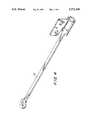
- FIG. 1is a representative outline perspective drawing of a laptop computer having no covering over the hinge elements and with the lid in an open position so that the display would be in position for use;
- FIG. 2is an exploded perspective view of the elements of our inventive hinge
- FIG. 3is a perspective view of the band of our inventive hinge
- FIG. 4is a perspective view of an alternative embodiment of the band of the inventive hinge.
- laptop computer 1consists of two major components that must be rotatably connected, one to the other, base 3 and lid 5.
- Lid 5contains display 7.
- Lid 5 and base 3are mechanically connected by pivot 9 on the left side and by the inventive friction hinge 11 on the right side.
- Pivot 9can be a conventional hinge of any convenient design. It may provide frictional torque, or it may be a simple torque free hinge, according to the requirement. Friction hinge 11 is more easily understood by an examination of FIG. 2, in which its four parts are shown in exploded view. Shaft 21 is fastened to base 3 and band 23 is fastened to lid 5. Shaft 21 and band 23 together comprise a conventional friction hinge in which band 23 is tightly wrapped about shaft 21 to produce frictional torque which tends to resist rotation of those elements with respect to one another.
- torsion rod 25is connected to base 3. In this instance, this has been accomplished by forming loop 27 in the end of the torsion rod and fastening it to base 1 with screw 29, however, any convenient connection method could be used instead.
- Driver 31has ears 33 which fit closely into matching notches 35 in band 23 which are best seen in FIG. 3.
- Driver 31is fastened to the other end, 37, of torsion rod 25 by any suitable connection method such as swaging, or crimping. It is also possible to form the torsion rod prior to heat treatment to form the driver and torsion rod as one piece. The objective is that the moment produced in torsion rod 25 act on end 39 of band 23.
- slot 43has been cut into band 23, separating part 41 of band 23 from the main body of the band except near end 39. Because of this separation, part 41 of band 23 acts as a socket to receive driver 31 and to form a torsionally rigid connection between end 37 of torsion rod 25 and end 39 of band 23.
- Friction hinges of the type formed by shaft 21 and band 23are in frequent use, and are well known to those skilled in the art. And, as mentioned above, torsion rods have often been used to equilibrate the weight of such things as lids and covers.
- the distinguishing feature of our inventive hingeis the connection of the torsion rod to the friction hinge in such a way that the torsion rod changes the amount of frictional torque provided by the hinge during the rotation of the lid.
- Athe angle of wrap of the band about the shaft.
- M(band)is the moment in the band produced by its expansion when it is placed over the shaft
- N(end)is any moment applied to the end of the band.
- the torsion rodis in its relaxed condition when lid 5 is vertical, perpendicular to base 3.
- torsion rod 25becomes wound, producing a restoring torque which tends to support the weight of lid 5.
- the resulting momentacts at end 39 of band 23 to reduce the frictional torque in the hinge which becomes lower as the lid is closed.
- the friction hingeproduces minimum torque, while the torsion rod exerts maximum torque to help raise the lid and prevent the base from lifting.
- the torsion rodis again relaxed, and the friction hinge produces friction according to the moment stored in the band.
- the torsion rodAs the lid is moved past vertical, approaching the position that would be normal for use in a laptop application, the torsion rod is wound in a direction that produces torque tending to lift the lid back toward the vertical position. In addition, the moment produced in the torsion rod now acts to increase the frictional torque produced by the hinge which helps to keep the lid and the display in position during use.
- This combination of torque from the friction hinge and from the torsion rodprovides extra stability for the display in the most critical position, particularly for touch-screen applications.
- the unique combination of torque due to the action of the friction hinge and the torsion spring and the control of the frictional torque by the torsion rodallows high holding torque when it is most needed while providing lower torque as the lid is closed, and substantially reduced torque for both directions of motion when the lid is near the closed position.
- Dead bandcan be achieved simply by leaving clearance under screw 29, or by looseness in the connections at right end 37 of torsion rod 25.
- FIG. 4depicts a one-piece band which can be used in place of the assembly whose parts are shown in FIG. 2.
- This bandhas torsion rod portion 51 formed as a part of the band itself.
- This methodeliminates the separate torsion rod and driver, and the assembly steps required to produce the assembly of those parts.
- the one-piece bandentails more scrap from the sheet metal blanking operations, and the forming is more difficult.
- the heat treatment of the one-piece bandcan be more troublesome because the requirements of the torsion rod and the friction hinge band portions of the part differ somewhat.
Landscapes
- Engineering & Computer Science (AREA)
- Computer Hardware Design (AREA)
- Theoretical Computer Science (AREA)
- Physics & Mathematics (AREA)
- General Engineering & Computer Science (AREA)
- General Physics & Mathematics (AREA)
- Human Computer Interaction (AREA)
- Mathematical Physics (AREA)
- Pivots And Pivotal Connections (AREA)
- Casings For Electric Apparatus (AREA)
- Hinge Accessories (AREA)
- Holders For Sensitive Materials And Originals (AREA)
- Springs (AREA)
Abstract
Description
T=M exp (uA)
Claims (19)
Priority Applications (7)
| Application Number | Priority Date | Filing Date | Title |
|---|---|---|---|
| US08/785,927US5771540A (en) | 1997-01-22 | 1997-01-22 | Equilibrated hinge with variable frictional torque |
| CA002277142ACA2277142A1 (en) | 1997-01-22 | 1997-12-02 | Equilibrated hinge with variable frictional torque |
| EP97950753AEP0954669A4 (en) | 1997-01-22 | 1997-12-02 | Equilibrated hinge with variable frictional torque |
| AU53673/98AAU718962B2 (en) | 1997-01-22 | 1997-12-02 | Equilibrated hinge with variable frictional torque |
| PCT/US1997/021923WO1998031908A1 (en) | 1997-01-22 | 1997-12-02 | Equilibrated hinge with variable frictional torque |
| TW086119949ATW368620B (en) | 1997-01-22 | 1997-12-30 | Equilibrated friction hinge with variable frictional torque |
| ARP980100188AAR011533A1 (en) | 1997-01-22 | 1998-01-16 | FRICTION JOINT SET FOR LAPTOP COMPUTER |
Applications Claiming Priority (1)
| Application Number | Priority Date | Filing Date | Title |
|---|---|---|---|
| US08/785,927US5771540A (en) | 1997-01-22 | 1997-01-22 | Equilibrated hinge with variable frictional torque |
Publications (1)
| Publication Number | Publication Date |
|---|---|
| US5771540Atrue US5771540A (en) | 1998-06-30 |
Family
ID=25137058
Family Applications (1)
| Application Number | Title | Priority Date | Filing Date |
|---|---|---|---|
| US08/785,927Expired - Fee RelatedUS5771540A (en) | 1997-01-22 | 1997-01-22 | Equilibrated hinge with variable frictional torque |
Country Status (7)
| Country | Link |
|---|---|
| US (1) | US5771540A (en) |
| EP (1) | EP0954669A4 (en) |
| AR (1) | AR011533A1 (en) |
| AU (1) | AU718962B2 (en) |
| CA (1) | CA2277142A1 (en) |
| TW (1) | TW368620B (en) |
| WO (1) | WO1998031908A1 (en) |
Cited By (59)
| Publication number | Priority date | Publication date | Assignee | Title |
|---|---|---|---|---|
| WO2000052560A1 (en)* | 1999-03-03 | 2000-09-08 | Psion Enterprise Computing Limited | Electronic apparatus including a lid |
| DE20021956U1 (en) | 2000-12-23 | 2001-03-15 | Schwarz Verbindungs-Systeme GmbH, 75382 Althengstett | Spring-loaded hinge and damping arrangement, in particular for a spring-loaded hinge |
| US6263542B1 (en)* | 1999-06-22 | 2001-07-24 | Lam Research Corporation | Tolerance resistant and vacuum compliant door hinge with open-assist feature |
| EP1201859A1 (en)* | 2000-09-29 | 2002-05-02 | Vaillant GmbH | Hinge for fastening a lid |
| US6490758B1 (en)* | 1999-04-22 | 2002-12-10 | Chuo Hatsujo Kabushiki Kaisha | Frictional hinge device |
| US6507977B2 (en)* | 2001-04-02 | 2003-01-21 | Lu Sheng-Nan | Computer hinge |
| US6510588B2 (en)* | 2000-05-30 | 2003-01-28 | Nokia Mobile Phones Ltd. | Turning mechanism for providing turning motion, and hinged electronic device |
| US6513197B2 (en) | 2000-11-22 | 2003-02-04 | Torqmaster, Inc. | Friction hinge with pop-up feature |
| US6634062B2 (en)* | 1999-12-24 | 2003-10-21 | Chuo Hatsujo Kabushiki Kaisha | Frictional hinge device and a portable business machine into which the frictional hinge device is incorporated |
| US6637796B1 (en) | 2002-11-22 | 2003-10-28 | Midway Products Group, Inc. | Vehicle tailgate hinge and counterbalance assembly |
| WO2004011302A3 (en)* | 2002-07-29 | 2004-03-25 | Raytheon Co | Friction hinge assembly for a mirror of a display unit |
| US6754081B2 (en) | 2002-01-22 | 2004-06-22 | Edward Rude | Pop-up friction hinge having multiple levels of torque |
| US20040181908A1 (en)* | 2003-03-17 | 2004-09-23 | Shin Zu Shing Co., Ltd. | Hinge for a notebook computer |
| US20040194256A1 (en)* | 2003-04-03 | 2004-10-07 | Wen-Hsiang Chen | Two-sided pop up structure for notebook/tablet PC |
| US20050028321A1 (en)* | 2003-08-04 | 2005-02-10 | Edward Rude | Reinforcer for wrapped band friction hinges |
| US20050199520A1 (en)* | 2002-05-01 | 2005-09-15 | Linak A/S | Electrical control panel preferably for height adjustable tables |
| US20060023408A1 (en)* | 2004-07-27 | 2006-02-02 | Dell Products L.P. | Snap-in floating hinge cap for portable computer |
| US7055215B1 (en)* | 2003-12-19 | 2006-06-06 | Apple Computer, Inc. | Hinge assembly |
| US20060185122A1 (en)* | 2003-08-01 | 2006-08-24 | Nhk Spring Co., Ltd. | Hinge device |
| US20060272128A1 (en)* | 2005-06-04 | 2006-12-07 | Torqmaster, Inc. | Friction hinge with angularly dependent torque |
| US20060272129A1 (en)* | 2005-06-04 | 2006-12-07 | Torqmaster, Inc. | Friction hinge with viscous damping |
| US20070039131A1 (en)* | 2005-08-16 | 2007-02-22 | Torqmaster, Inc. | Pop-up hinge with leaf spring |
| US20070079477A1 (en)* | 2005-06-10 | 2007-04-12 | Kuo-Hua Huang | Shaft structure |
| US20070163373A1 (en)* | 2006-01-06 | 2007-07-19 | Jarllytec Co., Ltd. | Labor-saving pivotal shaft structure |
| US20070252056A1 (en)* | 2006-03-27 | 2007-11-01 | Southco, Inc. | Display Mounting Apparatus |
| US20080137274A1 (en)* | 2006-12-07 | 2008-06-12 | Toshiba Tec Kabushiki Kaisha | Display device |
| USD582696S1 (en)* | 2007-08-21 | 2008-12-16 | Jason Kim | CD holder |
| US20090038119A1 (en)* | 2007-08-07 | 2009-02-12 | Edward Rude | Friction hinge without applied grease |
| US20090279943A1 (en)* | 2008-05-06 | 2009-11-12 | Microsoft Corporation | Flexible peripheral device positioner |
| US20110047750A1 (en)* | 2009-08-30 | 2011-03-03 | Southco, Inc. | Hinge assembly with a multi-layer torsion bar spring |
| US20130117967A1 (en)* | 2010-02-12 | 2013-05-16 | Sugatsune Kogyo Co., Ltd. | Hinge with torque setting function |
| US8784123B1 (en) | 2013-12-09 | 2014-07-22 | Google Inc. | Electrical connector |
| US8794981B1 (en) | 2013-12-12 | 2014-08-05 | Google Inc. | Electrical connector |
| US8821172B1 (en) | 2013-08-30 | 2014-09-02 | Google Inc. | Electrical connector and socket allowing connector to be rotated while preserving polarity |
| US8821181B1 (en) | 2013-10-09 | 2014-09-02 | Google Inc. | Electrical connector |
| US8851908B1 (en) | 2013-12-02 | 2014-10-07 | Google Inc. | Electrical connector with ground traces |
| US8887448B2 (en)* | 2013-04-08 | 2014-11-18 | Vault Access Solutions & Fabrications | Adjustable torsion lift assist system with one-way bias for traffic-rated utility vault cover |
| US8911262B1 (en) | 2013-12-09 | 2014-12-16 | Google Inc. | Electrical receptacle with lower speed signaling contacts farther from center |
| US9130289B2 (en) | 2012-08-02 | 2015-09-08 | Google Inc. | Power connector |
| US20160024827A1 (en)* | 2014-07-24 | 2016-01-28 | Michael Lambright | Door hinge closing mechanism |
| US9277812B2 (en) | 2010-07-08 | 2016-03-08 | Southco, Inc. | Display support with first and second arms and mechanism for maintaining constant orientation of the plane bisecting the range of rotation of the second arm relative to a support base |
| US9292049B1 (en)* | 2013-07-19 | 2016-03-22 | Google Inc. | Variable torque hinge with pass-through cable |
| US9348372B2 (en)* | 2014-06-13 | 2016-05-24 | Apple Inc. | Friction hinge with embedded counterbalance |
| US9388615B2 (en)* | 2014-05-20 | 2016-07-12 | Ami Industries, Inc. | Deformable stow box door hinge |
| US9477262B2 (en) | 2012-09-10 | 2016-10-25 | Google Inc. | Moveable display portion of a computing device including a clutch mechanism |
| US9620886B1 (en) | 2013-10-15 | 2017-04-11 | Google Inc. | Electrical connector with recessed contact and socket for receiving electrical connector |
| US9740240B1 (en) | 2016-03-21 | 2017-08-22 | Google Inc. | Base with rotating mount that increases friction of rotation when portable computing device is placed onto mount |
| US9752361B2 (en) | 2015-06-18 | 2017-09-05 | Microsoft Technology Licensing, Llc | Multistage hinge |
| US9964998B2 (en) | 2014-09-30 | 2018-05-08 | Microsoft Technology Licensing, Llc | Hinge mechanism with multiple preset positions |
| US10037057B2 (en) | 2016-09-22 | 2018-07-31 | Microsoft Technology Licensing, Llc | Friction hinge |
| US10344797B2 (en) | 2016-04-05 | 2019-07-09 | Microsoft Technology Licensing, Llc | Hinge with multiple preset positions |
| US10606322B2 (en) | 2015-06-30 | 2020-03-31 | Microsoft Technology Licensing, Llc | Multistage friction hinge |
| US10754392B2 (en) | 2017-08-29 | 2020-08-25 | Microsoft Technology Licensing, Llc | Friction hinge with clutch-based resistance |
| US11009921B1 (en)* | 2020-05-14 | 2021-05-18 | Apple Inc. | Electronic devices with adjustable hinges |
| US11131423B2 (en) | 2016-03-07 | 2021-09-28 | Southco, Inc. | Display support arm assembly for mounting a display |
| US11230868B2 (en)* | 2019-10-29 | 2022-01-25 | Nissan North America, Inc. | Torque rod for closure panel of vehicle |
| US11379012B2 (en) | 2018-02-08 | 2022-07-05 | Hewlett-Packard Development Company, L.P. | Hinge assemblies |
| US11856347B1 (en) | 2020-01-16 | 2023-12-26 | David M. Roberts | Speaker stand |
| US20250043610A1 (en)* | 2021-12-13 | 2025-02-06 | Reell Precision Manufacturing Corporation | Insert molded torsion bar hinge |
Citations (12)
| Publication number | Priority date | Publication date | Assignee | Title |
|---|---|---|---|---|
| US1102556A (en)* | 1913-09-11 | 1914-07-07 | Charles Manshel | Spring-hinge. |
| US3209391A (en)* | 1962-07-20 | 1965-10-05 | Fogel Refrigerator Company | Door closer |
| DE2325987A1 (en)* | 1972-05-24 | 1973-12-13 | Thomson Brandt | DOOR HINGE, IN PARTICULAR FOR REFRIGERATORS |
| US3787923A (en)* | 1972-01-17 | 1974-01-29 | Hager & Sons Hinge Mfg | Hinge with torsion bar |
| US3965533A (en)* | 1975-05-23 | 1976-06-29 | Bommer Spring Hinge Co. Inc. | Adjustable door spring hinge with fixed minimum tension |
| JPH02178480A (en)* | 1988-12-29 | 1990-07-11 | Nhk Spring Co Ltd | Opening/closing device |
| WO1990010818A1 (en)* | 1989-03-06 | 1990-09-20 | Dynabook Technologies Corporation | Torsion bar and band brake |
| US5079799A (en)* | 1990-11-14 | 1992-01-14 | General Clutch Corporation | Friction hinge assembly |
| US5231734A (en)* | 1991-11-04 | 1993-08-03 | General Clutch Corporation | Friction hinge assembly |
| US5333355A (en)* | 1992-10-15 | 1994-08-02 | Duane Beswick | Adjustable automatic door closure apparatus and method for use thereof |
| US5393160A (en)* | 1990-10-01 | 1995-02-28 | Nhk Spring Co., Ltd. | Torsion bar for slow-acting rotation shaft device |
| US5515876A (en)* | 1994-04-21 | 1996-05-14 | Premark Feg Corporation | Torsion bar assembly |
Family Cites Families (1)
| Publication number | Priority date | Publication date | Assignee | Title |
|---|---|---|---|---|
| US4787923A (en)* | 1986-08-27 | 1988-11-29 | Tennant Company | Apparatus for cleaning an air filter |
- 1997
- 1997-01-22USUS08/785,927patent/US5771540A/ennot_activeExpired - Fee Related
- 1997-12-02EPEP97950753Apatent/EP0954669A4/ennot_activeWithdrawn
- 1997-12-02CACA002277142Apatent/CA2277142A1/ennot_activeAbandoned
- 1997-12-02AUAU53673/98Apatent/AU718962B2/ennot_activeCeased
- 1997-12-02WOPCT/US1997/021923patent/WO1998031908A1/ennot_activeApplication Discontinuation
- 1997-12-30TWTW086119949Apatent/TW368620B/enactive
- 1998
- 1998-01-16ARARP980100188Apatent/AR011533A1/enunknown
Patent Citations (12)
| Publication number | Priority date | Publication date | Assignee | Title |
|---|---|---|---|---|
| US1102556A (en)* | 1913-09-11 | 1914-07-07 | Charles Manshel | Spring-hinge. |
| US3209391A (en)* | 1962-07-20 | 1965-10-05 | Fogel Refrigerator Company | Door closer |
| US3787923A (en)* | 1972-01-17 | 1974-01-29 | Hager & Sons Hinge Mfg | Hinge with torsion bar |
| DE2325987A1 (en)* | 1972-05-24 | 1973-12-13 | Thomson Brandt | DOOR HINGE, IN PARTICULAR FOR REFRIGERATORS |
| US3965533A (en)* | 1975-05-23 | 1976-06-29 | Bommer Spring Hinge Co. Inc. | Adjustable door spring hinge with fixed minimum tension |
| JPH02178480A (en)* | 1988-12-29 | 1990-07-11 | Nhk Spring Co Ltd | Opening/closing device |
| WO1990010818A1 (en)* | 1989-03-06 | 1990-09-20 | Dynabook Technologies Corporation | Torsion bar and band brake |
| US5393160A (en)* | 1990-10-01 | 1995-02-28 | Nhk Spring Co., Ltd. | Torsion bar for slow-acting rotation shaft device |
| US5079799A (en)* | 1990-11-14 | 1992-01-14 | General Clutch Corporation | Friction hinge assembly |
| US5231734A (en)* | 1991-11-04 | 1993-08-03 | General Clutch Corporation | Friction hinge assembly |
| US5333355A (en)* | 1992-10-15 | 1994-08-02 | Duane Beswick | Adjustable automatic door closure apparatus and method for use thereof |
| US5515876A (en)* | 1994-04-21 | 1996-05-14 | Premark Feg Corporation | Torsion bar assembly |
Cited By (89)
| Publication number | Priority date | Publication date | Assignee | Title |
|---|---|---|---|---|
| WO2000052560A1 (en)* | 1999-03-03 | 2000-09-08 | Psion Enterprise Computing Limited | Electronic apparatus including a lid |
| US6490758B1 (en)* | 1999-04-22 | 2002-12-10 | Chuo Hatsujo Kabushiki Kaisha | Frictional hinge device |
| US6263542B1 (en)* | 1999-06-22 | 2001-07-24 | Lam Research Corporation | Tolerance resistant and vacuum compliant door hinge with open-assist feature |
| US6634062B2 (en)* | 1999-12-24 | 2003-10-21 | Chuo Hatsujo Kabushiki Kaisha | Frictional hinge device and a portable business machine into which the frictional hinge device is incorporated |
| US6510588B2 (en)* | 2000-05-30 | 2003-01-28 | Nokia Mobile Phones Ltd. | Turning mechanism for providing turning motion, and hinged electronic device |
| EP1201859A1 (en)* | 2000-09-29 | 2002-05-02 | Vaillant GmbH | Hinge for fastening a lid |
| US6513197B2 (en) | 2000-11-22 | 2003-02-04 | Torqmaster, Inc. | Friction hinge with pop-up feature |
| DE20021956U1 (en) | 2000-12-23 | 2001-03-15 | Schwarz Verbindungs-Systeme GmbH, 75382 Althengstett | Spring-loaded hinge and damping arrangement, in particular for a spring-loaded hinge |
| US6507977B2 (en)* | 2001-04-02 | 2003-01-21 | Lu Sheng-Nan | Computer hinge |
| US6754081B2 (en) | 2002-01-22 | 2004-06-22 | Edward Rude | Pop-up friction hinge having multiple levels of torque |
| US20050199520A1 (en)* | 2002-05-01 | 2005-09-15 | Linak A/S | Electrical control panel preferably for height adjustable tables |
| US20040134033A1 (en)* | 2002-07-29 | 2004-07-15 | Aaron Raines | Friction hinge assembly for a mirror of a display unit |
| WO2004011302A3 (en)* | 2002-07-29 | 2004-03-25 | Raytheon Co | Friction hinge assembly for a mirror of a display unit |
| US6637796B1 (en) | 2002-11-22 | 2003-10-28 | Midway Products Group, Inc. | Vehicle tailgate hinge and counterbalance assembly |
| US20040181908A1 (en)* | 2003-03-17 | 2004-09-23 | Shin Zu Shing Co., Ltd. | Hinge for a notebook computer |
| US20040194256A1 (en)* | 2003-04-03 | 2004-10-07 | Wen-Hsiang Chen | Two-sided pop up structure for notebook/tablet PC |
| US20060185122A1 (en)* | 2003-08-01 | 2006-08-24 | Nhk Spring Co., Ltd. | Hinge device |
| US7036187B2 (en) | 2003-08-04 | 2006-05-02 | Torqmaster, Inc. | Reinforcer for wrapped band friction hinges |
| US20050028321A1 (en)* | 2003-08-04 | 2005-02-10 | Edward Rude | Reinforcer for wrapped band friction hinges |
| US7055215B1 (en)* | 2003-12-19 | 2006-06-06 | Apple Computer, Inc. | Hinge assembly |
| US20070201200A1 (en)* | 2004-07-27 | 2007-08-30 | Dell Products L.P. | Snap-in floating hinge cap for portable computer |
| US20060023408A1 (en)* | 2004-07-27 | 2006-02-02 | Dell Products L.P. | Snap-in floating hinge cap for portable computer |
| US7631410B2 (en) | 2004-07-27 | 2009-12-15 | Dell Products L.P. | Snap-in floating hinge cap for portable computer |
| US7602606B2 (en) | 2004-07-27 | 2009-10-13 | Dell Products L.P. | Snap-in floating hinge cap for portable computer |
| US20070201199A1 (en)* | 2004-07-27 | 2007-08-30 | Dell Products L.P. | Snap-in floating hinge cap for portable computer |
| US7239504B2 (en) | 2004-07-27 | 2007-07-03 | Dell Products L.P. | Snap-in floating hinge cap for portable computer |
| US20060272129A1 (en)* | 2005-06-04 | 2006-12-07 | Torqmaster, Inc. | Friction hinge with viscous damping |
| WO2006132787A3 (en)* | 2005-06-04 | 2007-11-29 | Torqmaster Inc | Friction hinge with angularly dependent torque |
| US20060272128A1 (en)* | 2005-06-04 | 2006-12-07 | Torqmaster, Inc. | Friction hinge with angularly dependent torque |
| US20070079477A1 (en)* | 2005-06-10 | 2007-04-12 | Kuo-Hua Huang | Shaft structure |
| US20070039131A1 (en)* | 2005-08-16 | 2007-02-22 | Torqmaster, Inc. | Pop-up hinge with leaf spring |
| US20070163373A1 (en)* | 2006-01-06 | 2007-07-19 | Jarllytec Co., Ltd. | Labor-saving pivotal shaft structure |
| US7743466B2 (en)* | 2006-01-06 | 2010-06-29 | Jarllytec Co., Ltd. | Labor-saving pivotal shaft structure |
| US20070252056A1 (en)* | 2006-03-27 | 2007-11-01 | Southco, Inc. | Display Mounting Apparatus |
| US8888062B2 (en) | 2006-03-27 | 2014-11-18 | Southco, Inc. | Display mounting apparatus |
| US20080137274A1 (en)* | 2006-12-07 | 2008-06-12 | Toshiba Tec Kabushiki Kaisha | Display device |
| EP1930646A3 (en)* | 2006-12-07 | 2009-07-15 | Toshiba Tec Kabushiki Kaisha | Display device |
| US7660106B2 (en) | 2006-12-07 | 2010-02-09 | Toshiba Tec Kabushiki Kaisha | Display device |
| US20100085698A1 (en)* | 2006-12-07 | 2010-04-08 | Toshiba Tec Kabushiki Kaisha | Display device |
| US7957129B2 (en) | 2006-12-07 | 2011-06-07 | Toshiba Tec Kabushiki Kaisha | Display device |
| US20090038119A1 (en)* | 2007-08-07 | 2009-02-12 | Edward Rude | Friction hinge without applied grease |
| USD582696S1 (en)* | 2007-08-21 | 2008-12-16 | Jason Kim | CD holder |
| US20090279943A1 (en)* | 2008-05-06 | 2009-11-12 | Microsoft Corporation | Flexible peripheral device positioner |
| US8152402B2 (en) | 2008-05-06 | 2012-04-10 | Microsoft Corporation | Flexible peripheral device positioner |
| US8549710B2 (en)* | 2009-08-30 | 2013-10-08 | Southco, Inc. | Hinge assembly with a multi-layer torsion bar spring |
| US20110047750A1 (en)* | 2009-08-30 | 2011-03-03 | Southco, Inc. | Hinge assembly with a multi-layer torsion bar spring |
| US8732907B2 (en)* | 2009-08-30 | 2014-05-27 | Southco, Inc. | Hinge assembly with a multi-layer torsion bar spring |
| DE112010003488B4 (en)* | 2009-08-30 | 2025-09-11 | Southco, Inc. | HINGE CONSTRUCTION WITH MULTI-LAYER TORSION BAR SPRING |
| US8732908B2 (en)* | 2010-02-12 | 2014-05-27 | Sugatsune Kogyo Co., Ltd. | Hinge with torque setting function |
| US20130117967A1 (en)* | 2010-02-12 | 2013-05-16 | Sugatsune Kogyo Co., Ltd. | Hinge with torque setting function |
| US10400946B2 (en) | 2010-07-08 | 2019-09-03 | Southco, Inc. | Display support apparatus |
| US9277812B2 (en) | 2010-07-08 | 2016-03-08 | Southco, Inc. | Display support with first and second arms and mechanism for maintaining constant orientation of the plane bisecting the range of rotation of the second arm relative to a support base |
| US9130289B2 (en) | 2012-08-02 | 2015-09-08 | Google Inc. | Power connector |
| US9564723B2 (en) | 2012-08-02 | 2017-02-07 | Google Inc. | Power connector |
| US9477262B2 (en) | 2012-09-10 | 2016-10-25 | Google Inc. | Moveable display portion of a computing device including a clutch mechanism |
| US8887448B2 (en)* | 2013-04-08 | 2014-11-18 | Vault Access Solutions & Fabrications | Adjustable torsion lift assist system with one-way bias for traffic-rated utility vault cover |
| US9292049B1 (en)* | 2013-07-19 | 2016-03-22 | Google Inc. | Variable torque hinge with pass-through cable |
| US8821172B1 (en) | 2013-08-30 | 2014-09-02 | Google Inc. | Electrical connector and socket allowing connector to be rotated while preserving polarity |
| US9106016B1 (en) | 2013-10-09 | 2015-08-11 | Google Inc. | Electrical connector |
| US8821181B1 (en) | 2013-10-09 | 2014-09-02 | Google Inc. | Electrical connector |
| US10027056B1 (en) | 2013-10-15 | 2018-07-17 | Google Llc | Electrical connector |
| US9620886B1 (en) | 2013-10-15 | 2017-04-11 | Google Inc. | Electrical connector with recessed contact and socket for receiving electrical connector |
| US8851908B1 (en) | 2013-12-02 | 2014-10-07 | Google Inc. | Electrical connector with ground traces |
| US9774156B2 (en) | 2013-12-09 | 2017-09-26 | Google Inc. | Electrical connector |
| US8784123B1 (en) | 2013-12-09 | 2014-07-22 | Google Inc. | Electrical connector |
| US8911262B1 (en) | 2013-12-09 | 2014-12-16 | Google Inc. | Electrical receptacle with lower speed signaling contacts farther from center |
| US8794981B1 (en) | 2013-12-12 | 2014-08-05 | Google Inc. | Electrical connector |
| US9803406B2 (en) | 2014-05-20 | 2017-10-31 | Ami Industries, Inc. | Deformable stow box door hinge |
| US9388615B2 (en)* | 2014-05-20 | 2016-07-12 | Ami Industries, Inc. | Deformable stow box door hinge |
| US9348372B2 (en)* | 2014-06-13 | 2016-05-24 | Apple Inc. | Friction hinge with embedded counterbalance |
| US10392847B2 (en) | 2014-07-24 | 2019-08-27 | Michael Lambright | Door hinge closing mechanism |
| US9725940B2 (en)* | 2014-07-24 | 2017-08-08 | Michael Lambright | Door hinge closing mechanism |
| US20160024827A1 (en)* | 2014-07-24 | 2016-01-28 | Michael Lambright | Door hinge closing mechanism |
| US9964998B2 (en) | 2014-09-30 | 2018-05-08 | Microsoft Technology Licensing, Llc | Hinge mechanism with multiple preset positions |
| US9752361B2 (en) | 2015-06-18 | 2017-09-05 | Microsoft Technology Licensing, Llc | Multistage hinge |
| US10606322B2 (en) | 2015-06-30 | 2020-03-31 | Microsoft Technology Licensing, Llc | Multistage friction hinge |
| US11131423B2 (en) | 2016-03-07 | 2021-09-28 | Southco, Inc. | Display support arm assembly for mounting a display |
| US11543070B2 (en) | 2016-03-07 | 2023-01-03 | Southco, Inc. | Display support arm assembly for mounting a display |
| US11536416B2 (en) | 2016-03-07 | 2022-12-27 | Southco, Inc. | Display support arm assembly for mounting a display |
| US11506329B2 (en) | 2016-03-07 | 2022-11-22 | Southco, Inc. | Display support arm assembly for mounting a display |
| US9740240B1 (en) | 2016-03-21 | 2017-08-22 | Google Inc. | Base with rotating mount that increases friction of rotation when portable computing device is placed onto mount |
| US10344797B2 (en) | 2016-04-05 | 2019-07-09 | Microsoft Technology Licensing, Llc | Hinge with multiple preset positions |
| US10037057B2 (en) | 2016-09-22 | 2018-07-31 | Microsoft Technology Licensing, Llc | Friction hinge |
| US10754392B2 (en) | 2017-08-29 | 2020-08-25 | Microsoft Technology Licensing, Llc | Friction hinge with clutch-based resistance |
| US11379012B2 (en) | 2018-02-08 | 2022-07-05 | Hewlett-Packard Development Company, L.P. | Hinge assemblies |
| US11230868B2 (en)* | 2019-10-29 | 2022-01-25 | Nissan North America, Inc. | Torque rod for closure panel of vehicle |
| US11856347B1 (en) | 2020-01-16 | 2023-12-26 | David M. Roberts | Speaker stand |
| US11009921B1 (en)* | 2020-05-14 | 2021-05-18 | Apple Inc. | Electronic devices with adjustable hinges |
| US20250043610A1 (en)* | 2021-12-13 | 2025-02-06 | Reell Precision Manufacturing Corporation | Insert molded torsion bar hinge |
Also Published As
| Publication number | Publication date |
|---|---|
| AR011533A1 (en) | 2000-08-30 |
| CA2277142A1 (en) | 1998-07-23 |
| AU718962B2 (en) | 2000-05-04 |
| TW368620B (en) | 1999-09-01 |
| WO1998031908A1 (en) | 1998-07-23 |
| EP0954669A4 (en) | 2000-03-22 |
| AU5367398A (en) | 1998-08-07 |
| EP0954669A1 (en) | 1999-11-10 |
Similar Documents
| Publication | Publication Date | Title |
|---|---|---|
| US5771540A (en) | Equilibrated hinge with variable frictional torque | |
| US6754081B2 (en) | Pop-up friction hinge having multiple levels of torque | |
| US5566048A (en) | Hinge assembly for a device having a display | |
| US5231734A (en) | Friction hinge assembly | |
| JPH057629Y2 (en) | ||
| US5771539A (en) | Torsion friction spring hinge | |
| US5168426A (en) | Hinge mechanism for cover panel of portable computer including slide mechanism | |
| EP3049885B1 (en) | Frictional hinge for electronic devices | |
| US6510588B2 (en) | Turning mechanism for providing turning motion, and hinged electronic device | |
| US20020167789A1 (en) | Hinge assembly for rotatably mounting a display to a surface | |
| US20020059690A1 (en) | Friction hinge with pop-up feature | |
| US5749124A (en) | Hinge for notebook computer | |
| US4352222A (en) | Hinge | |
| US5799372A (en) | System for supporting a monitor | |
| KR100327397B1 (en) | pedestal assembly for video display appliance | |
| JPH08121009A (en) | Hinge mechanism | |
| JP2001065543A (en) | Opening and closing torque variable tilt hinge | |
| CN216083556U (en) | Screen hinge structure and notebook computer | |
| US7661176B2 (en) | Hinge assembly | |
| JP2005155820A (en) | Hinge | |
| JPH1051156A (en) | Angle adjustment stand for electronic equipment | |
| GB2286011A (en) | Friction hinge | |
| EP1431493B1 (en) | Variable-force balancing device in particular for movable-axis hinges of electric household appliances and the like | |
| JP2571896Y2 (en) | Tilt mechanism for small electronic devices | |
| US20030131446A1 (en) | Adjustable hinge |
Legal Events
| Date | Code | Title | Description |
|---|---|---|---|
| AS | Assignment | Owner name:TORQMASTER, CONNECTICUT Free format text:ASSIGNMENT OF ASSIGNORS INTEREST;ASSIGNORS:CARPENTER, DAVID A.;GELFAND, MIKHAIL;RUDE, EDWARD T.;REEL/FRAME:008482/0318 Effective date:19970410 | |
| FPAY | Fee payment | Year of fee payment:4 | |
| AS | Assignment | Owner name:GENERAL CLUTCH CORP., CONNECTICUT Free format text:ORDER FOR PREJUDGMENT REMEDY;ASSIGNOR:TORQMASTER, INC.;REEL/FRAME:015394/0113 Effective date:20040826 | |
| AS | Assignment | Owner name:GENERAL CLUTCH CORP., CONNECTICUT Free format text:JUDGMENT LIEN CERTIFICATE AND JUDGMENT;ASSIGNOR:TORQMASTER, INC.;REEL/FRAME:015972/0324 Effective date:20050208 | |
| FPAY | Fee payment | Year of fee payment:8 | |
| AS | Assignment | Owner name:ROLLEASE, INC., CONNECTICUT Free format text:MERGER;ASSIGNOR:GENERAL CLUTCH CORP.;REEL/FRAME:019668/0838 Effective date:20070731 | |
| AS | Assignment | Owner name:JOHN F. TAYLOR TRUST, VERMONT Free format text:SECURITY AGREEMENT;ASSIGNOR:TORQMASTER;REEL/FRAME:021029/0662 Effective date:20080602 | |
| REMI | Maintenance fee reminder mailed | ||
| LAPS | Lapse for failure to pay maintenance fees | ||
| STCH | Information on status: patent discontinuation | Free format text:PATENT EXPIRED DUE TO NONPAYMENT OF MAINTENANCE FEES UNDER 37 CFR 1.362 | |
| FP | Lapsed due to failure to pay maintenance fee | Effective date:20100630 |