US5771461A - Method and apparatus for power control of a first channel based on a signal quality of a second channel - Google Patents
Method and apparatus for power control of a first channel based on a signal quality of a second channelDownload PDFInfo
- Publication number
- US5771461A US5771461AUS08/672,703US67270396AUS5771461AUS 5771461 AUS5771461 AUS 5771461AUS 67270396 AUS67270396 AUS 67270396AUS 5771461 AUS5771461 AUS 5771461A
- Authority
- US
- United States
- Prior art keywords
- remote unit
- power
- signal quality
- channel
- quality metric
- Prior art date
- Legal status (The legal status is an assumption and is not a legal conclusion. Google has not performed a legal analysis and makes no representation as to the accuracy of the status listed.)
- Expired - Lifetime
Links
Images


Classifications
- H—ELECTRICITY
- H04—ELECTRIC COMMUNICATION TECHNIQUE
- H04B—TRANSMISSION
- H04B7/00—Radio transmission systems, i.e. using radiation field
- H04B7/24—Radio transmission systems, i.e. using radiation field for communication between two or more posts
- H04B7/26—Radio transmission systems, i.e. using radiation field for communication between two or more posts at least one of which is mobile
- H—ELECTRICITY
- H04—ELECTRIC COMMUNICATION TECHNIQUE
- H04W—WIRELESS COMMUNICATION NETWORKS
- H04W52/00—Power management, e.g. Transmission Power Control [TPC] or power classes
- H04W52/04—Transmission power control [TPC]
- H04W52/06—TPC algorithms
- H04W52/16—Deriving transmission power values from another channel
- G—PHYSICS
- G01—MEASURING; TESTING
- G01S—RADIO DIRECTION-FINDING; RADIO NAVIGATION; DETERMINING DISTANCE OR VELOCITY BY USE OF RADIO WAVES; LOCATING OR PRESENCE-DETECTING BY USE OF THE REFLECTION OR RERADIATION OF RADIO WAVES; ANALOGOUS ARRANGEMENTS USING OTHER WAVES
- G01S11/00—Systems for determining distance or velocity not using reflection or reradiation
- G01S11/02—Systems for determining distance or velocity not using reflection or reradiation using radio waves
- G01S11/06—Systems for determining distance or velocity not using reflection or reradiation using radio waves using intensity measurements
- H—ELECTRICITY
- H04—ELECTRIC COMMUNICATION TECHNIQUE
- H04W—WIRELESS COMMUNICATION NETWORKS
- H04W52/00—Power management, e.g. Transmission Power Control [TPC] or power classes
- H04W52/04—Transmission power control [TPC]
- H04W52/18—TPC being performed according to specific parameters
- H—ELECTRICITY
- H04—ELECTRIC COMMUNICATION TECHNIQUE
- H04W—WIRELESS COMMUNICATION NETWORKS
- H04W52/00—Power management, e.g. Transmission Power Control [TPC] or power classes
- H04W52/04—Transmission power control [TPC]
- H04W52/18—TPC being performed according to specific parameters
- H04W52/28—TPC being performed according to specific parameters using user profile, e.g. mobile speed, priority or network state, e.g. standby, idle or non-transmission
- H04W52/282—TPC being performed according to specific parameters using user profile, e.g. mobile speed, priority or network state, e.g. standby, idle or non-transmission taking into account the speed of the mobile
- H—ELECTRICITY
- H04—ELECTRIC COMMUNICATION TECHNIQUE
- H04W—WIRELESS COMMUNICATION NETWORKS
- H04W52/00—Power management, e.g. Transmission Power Control [TPC] or power classes
- H04W52/04—Transmission power control [TPC]
- H04W52/18—TPC being performed according to specific parameters
- H04W52/28—TPC being performed according to specific parameters using user profile, e.g. mobile speed, priority or network state, e.g. standby, idle or non-transmission
- H04W52/283—Power depending on the position of the mobile
Definitions
- the present inventionrelates generally to spread-spectrum communication systems and, in particular, to power control in a spread-spectrum communication system.
- Communication systemsare known to employ power control methods that control forward-link transmission energy.
- a communication system employing forward-link power controlis a spread-spectrum communication system. Because many forward-link signals in a spread-spectrum system are typically transmitted on the same frequency, a majority of the noise (which is inversely proportional to bit energy per noise+interference density i.e., E b /N o ) associated with a received signal can be attributed to other forward-link transmissions. The magnitude of this noise is directly related to the received signal power of each of the other forward-link transmissions.
- cellular infrastructure equipmentsuch as a cellular base station
- TIA/EIA/IS-95-ACellular System Remote unit-Base Station Compatibility Standard of the Electronic Industry A36,283 Association Interim Standard 95
- EIA/TIAcan be contacted at 2001 Pennsylvania Ave. NW Washington D.C. 20006
- initial forward-link gainmust be set high enough to guarantee an acceptable link. Since the channel between the base station and the remote unit is unknown at the time of origination, the call is originated at a maximum forward-link gain and then powered down accordingly. Because TIA/EIA/IS-95-A forward-link power control is very slow to update (on the order of once every four seconds), the base station can transmit at an unacceptably high forward-link gain for extended periods of time, needlessly contributing to system noise.
- FIG. 1is a block diagram of a preferred embodiment of a base station receiver that can utilize the present invention.
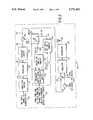
- FIG. 2is a block diagram of a base station transmitter in accordance with a preferred embodiment of the present invention.
- FIG. 3is a block diagram of a preferred embodiment of an initial forward power control computer of FIG. 2.
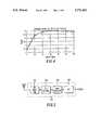
- FIG. 4illustrates a relationship between remote unit speed and E b /N 0 for a 1% frame erasure rate.
- FIG. 5is a block diagram of a preferred embodiment of a speed computer of FIG. 3.
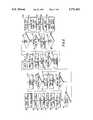
- FIG. 6is a flow chart of a preferred embodiment of operating a base station transmitter of FIG. 2 during call origination in accordance with a preferred embodiment of the present invention.
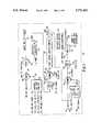
- FIG. 7is a block diagram of a preferred embodiment of a post-origination forward power control computer of FIG. 2.
- FIG. 8is a flow chart of a preferred embodiment of operating a post-origination forward power control computer of FIG. 2.
- FIGS. 9A and 9Billustrate a time-domain diagram of forward-link power in accordance with a preferred embodiment of the invention.
- the present inventionaddresses the above-mentioned problem by determining origination power of a traffic channel based on a number of active demodulators and pilot channel signal quality. Once origination transmit power is determined and call origination takes place, the transmit power is reduced at a first rate when a time is less than a time for all active demodulators to be established, otherwise the transmit power is reduced at a second rate. After all active demodulators have been acquired power control takes place by receiving a Power Measurement Report Message (PMRM) or a Pilot Strength Measurement Message (PSMM), determining, a signal quality metric existing at the remote unit based on the PMRM or PSMM, and adjusting transmit power based on the signal quality metric.
- PMRMPower Measurement Report Message
- PSMMPilot Strength Measurement Message
- the present inventionencompasses a method for power control in a communication system by communicating, via a first base station, to a remote unit on a first channel at a first power level. Next, a determination of a signal quality metric of the first channel is made, and finally a call is originated via the first base station on a second channel at a second power level based on the signal quality metric.
- Another aspect of the present inventionencompasses a method of power control in a communication system comprising the steps of transmitting on a first channel, at a first power level, the first power level based on a number of active demodulators, and reducing the first power level at a first rate when a time is less than a time for all active demodulators to be established, otherwise reducing the first power level at a second rate.
- Another aspect of the present inventionencompasses a method of power control in a communication system comprising the steps of transmitting from cellular infrastructure equipment to a remote unit at a first power level and receiving, by the cellular infrastructure equipment, a Power Measurement Report Message (PMRM) or a Pilot Strength Measurement Message (PSMM). Next, a determination of signal quality existing at the remote unit is made based on the PMRM or PSMM. Finally the transmission from the remote unit is broadcast at a second power level based on the signal quality.
- PMRMPower Measurement Report Message
- PSMMPilot Strength Measurement Message
- Another aspect of the present inventionencompasses an apparatus for power control in a communication system, the apparatus comprising cellular infrastructure equipment communicating, via a first base station, to a remote unit on a first channel at a first power level, and an instantaneous traffic channel gain estimation computer (ITC) coupled to the cellular infrastructure equipment, the ITC determining a signal quality metric of the first channel and originating a call, via the first base station, on a second channel at a second power level based on the signal quality metric.
- ITCinstantaneous traffic channel gain estimation computer
- Another aspect of the present inventionencompasses an apparatus for power control in a communication system, the apparatus comprising cellular infrastructure equipment transmitting on a first channel, at a first power level, the first power level based on a number of active demodulators, and an initial forward power control computer (IFC) coupled to the cellular infrastructure equipment, the IFC reducing the first power level at a first rate when a time is less than a time for all active demodulators to be established, otherwise reducing the power level at a second rate.
- IFCinitial forward power control computer
- Another aspect of the present inventionencompasses an apparatus for power control in a communication system, the apparatus comprising cellular infrastructure equipment transmitting to a remote unit at a first power level, the cellular infrastructure equipment receiving a Power Measurement Report Message (PMRM) or a Pilot Strength Measurement Message (PSMM).
- the apparatusadditionally comprises a post-initial forward power control computer (PFC) coupled to the cellular infrastructure equipment, the PFC determining a signal quality metric existing at the remote unit wherein the signal quality metric is based on the received message and transmitting to the remote unit at a second power level based on the determination.
- PMRMPower Measurement Report Message
- PSMMPilot Strength Measurement Message
- FIG. 1is a block diagram of a preferred embodiment of a base station receiver 100 for receiving a signal transmitted by a remote unit.
- Orthogonally encoded spread-spectrum digital signal 130is received at receive antenna 131 and amplified by receiver 132 before being despread and demodulated 136 into in-phase 140 and quadrature 138 components.
- Components 138, 140 of despread digital samplesare then grouped into predetermined length groups (e.g., 64 sample length groups) of sampled signals that are independently input to orthogonal decoders in the form of fast Hadamard transformers 142, 144, which despread the orthogonally encoded signal components producing a plurality of despread signal components 146 and 160, respectively (e.g.
- each transformer output signal 146, 160has an associated Walsh index symbol which identifies each particular orthogonal code from within a set of mutually orthogonal codes (e.g. when 64 sample length groups are input, then a 6 bit length index data symbol can be associated with the transformer output signal to indicate the particular 64 bit length orthogonal code to which the transformer output signal corresponds).
- the energy values with the same Walsh index in each group of resulting signal 156 from each branch of receiver 100will then be summed at summer 164 to provide a group of summed energy values 166.
- the energy value with index i in the group of summed energy values 166corresponds to a measure of confidence that the group of sampled signals, which generate this group of summed energy values 166, corresponds to the i-th Walsh symbol.
- the group of summed energy values with associated indiceswill then be sent to a soft decision metric generator 168 where a single metric for each encoded data bit is determined, thereby producing a single set of aggregate soft decision data 170.
- the aggregate soft decision data 170is then deinterleaved by deinterleaver 172 prior to final maximum likelihood decoding by decoder 176.
- FIG. 2is a block diagram of a preferred embodiment of a CDMA transmitter 200 for transmitting a signal to a remote unit over a single channel.
- Transmitter 200includes convolutional encoder 212, interleaver 216, orthogonal encoder 220, modulator 252, upconverter 256, instantaneous traffic channel gain estimation computer (ITC) 201, post-initial forward power control computer (PFC) 239, initial forward power control computer (IFC) 236, switch 243, and antenna 258.
- ITCinstantaneous traffic channel gain estimation computer
- PFCpost-initial forward power control computer
- IFCinitial forward power control computer
- signal 210(traffic channel data bits) is received by convolutional encoder 212 at a particular bit rate (e.g., 9.6 kbit/second).
- Input traffic channel data 210 bitstypically include voice converted to data by a vocoder, pure data, or a combination of the two types of data.
- Convolutional encoder 212encodes input data bits 210 into data symbols at a fixed encoding rate with an encoding algorithm which facilitates subsequent maximum likelihood decoding of the data symbols into data bits (e.g. convolutional or block coding algorithms).
- convolutional encoder 212encodes input data bits 210 (received at a rate of 9.6 kbit/second) at a fixed encoding rate of one data bit to two data symbols (i.e., rate 1/2) such that convolutional encoder 212 outputs data symbols 214 at a 19.2 ksymbol/second rate.
- Data symbols 214are then input into interleaver 216.
- Interleaver 216interleaves the input data symbols 214 at the symbol level.
- data symbols 214are individually input into a matrix which defines a predetermined size block of data symbols 214.
- Data symbols 214are input into locations within a matrix so that the matrix is filled in a column by column manner.
- Data symbols 214are individually output from locations within the matrix so that the matrix is emptied in a row by row manner.
- the matrixis a square matrix having a number of rows equal to the number of columns; however, other matrix forms can be chosen to increase the output interleaving distance between the consecutively input non-interleaved data symbols.
- Interleaved data symbols 218are output by interleaver 216 at the same data symbol rate that they were input (e.g., 19.2 ksymbol/second).
- the predetermined size of the block of data symbols defined by the matrixis derived from the maximum number of data symbols which can be transmitted at a predetermined symbol rate within a predetermined length transmission block. For example, if the predetermined length of the transmission block is 20 milliseconds, then the predetermined size of the block of data symbols is 19.2 ksymbol/second times 20 milliseconds which equals 384 data symbols which defines a 16 by 24 matrix.
- Interleaved data symbols 218are input to orthogonal encoder 220.
- Orthogonal encoder 220 modulo 2adds an orthogonal code (e.g., a 64-ary Walsh code) to each interleaved and scrambled data symbol 218.
- an orthogonal codee.g., a 64-ary Walsh code
- interleaved and scrambled data symbols 218are each replaced by a 64 symbol orthogonal code or its inverse.
- These 64 orthogonal codespreferably correspond to Walsh codes from a 64 by 64 Hadamard matrix wherein a Walsh code is a single row or column of the matrix.
- Orthogonal encoder 220respetitively outputs a Walsh code or its inverse 222 which corresponds to input data symbol 218 at a fixed symbol rate (e.g., 19.2 ksymbol/second).
- IFC 236 and PFC 239update traffic channel gain values Gtch -- IFC 238 and Gtch -- PFC 241 respectively to minimize forward link interference while preserving adequate voice channel quality.
- instantaneous traffic channel gain estimate computer (ITC) 201computes instantaneous traffic channel gain estimate (Gtch -- ITC) 211 as a function of a signal quality metric (e.g. pilot channel Ec/Io) and remote unit speed.
- Origination traffic channel gain value (Gtch_lFC) 238is determined by IFC 236, and is a function of forward link quality measurements (e.g. TCH frame quality and frame quality history) performed by the remote unit along with Gtch -- ITC 211.
- PFC 239determines post-initial (post remote unit call origination/termination) forward traffic channel gain value (Gtch -- PFC) 241 based on forward link quality measurements performed by the remote unit and Gtch -- ITC 211.
- Switch 243selects the appropriate traffic channel gain value Gtch -- IFC 238 or Gtch -- PFC 241 (depending on the call state) resulting in a selected traffic channel gain value (Gtch) 244.
- Switch 243chooses Gtch -- IFC 238 at the start of a remote unit call until a stable handoff state has been achieved subsequently it chooses Gtch -- PFC 241.
- Gtch 244is then output to multiplier 240, which multiplies Walsh code's 222 amplitude by gain value Gtch 244 resulting in a sequence of weighted Walsh codes 242. Sequence of weighted Walsh codes 242 is prepared for transmission over a communication channel by modulator 252.
- the spreading codeis a user specific sequence of symbols or unique user code which is output at a fixed chip rate (e.g., 1.228 Mchip/second).
- the user code spread encoded chipsare scrambled by a pair of short pseudorandom codes 224 (i.e. short when compared to the long code) to generate an I-channel and Q-channel code spread sequence 226.
- the I-channel and Q-channel code spread sequences 226are used to bi-phase modulate a quadrature pair of sinusoids by driving the power level controls of the pair of sinusoids.
- the sinusoids output signalsare summed, bandpass filtered, translated to an RF frequency, amplified, filtered via upconverter 256 and radiated by antenna 258 to complete transmission of channel data bits 210.
- FIG. 3is a block diagram of a preferred embodiment of ITC 201 of FIG. 2.
- ITC 201comprises pilot fraction computer 312, multiplier 316, summer 320, multiplier 330, lookup table 326, square root calculator 336, multiplier 340 and selector 310.
- instantaneous traffic channel gain estimate (Gtch -- ITC) 211is computed based on a signal quality metric such as pilot channel E c /I o measured with respect to the serving base station. (The pilot channel is a forward link that is continuously broadcast to the remote unit that controls remote unit timing).
- Gtch -- ITC 211based on pilot channel E c /I o
- forward-link gain upon call originationis additionally based on remote unit speed.
- Gtch -- ITC 211Prior to describing the operation of ITC 201, it will be beneficial to describe the relationship between Gtch -- ITC 211 and three variables utilized in determining Gtch -- lTC 211 (pilot E c /I or , pilot E c /I o , required E b /N o for 1% Forward Error Rate (FER)).
- pilot E c /I or , pilot E c /I orequired E b /N o for 1% Forward Error Rate (FER)
- FERForward Error Rate
- P cell (i)--total power transmitted by cell Ialso represented as IorW ##EQU2## interference from other (non serving) cells seen at remote unit k N th W--AWGN noise due to receiver and/or other non-CDMA sources
- equation (6)is specific to the single ray case.
- the typical degradation with respect to two equal rays seen for remote units for varying ray power imbalancesis less than 3 dB for every 6 dB of imbalance when considering imbalances less than 12 dB.
- the degradationis about 1.5 dB for every 6 dB.
- ITC 201Operation of ITC 201 occurs as follows: Current control channel and traffic channel gains for all forward links utilized by the communication system are input into pilot fraction computer 312. Pilot fraction computer 312 utilizes the current control channel and traffic channel gains to compute the current pilot E c /I or based on the above 25 equations.
- the current pilot E c /I oris output to multiplier 316 where it is scaled by an estimate of the current pilot E c /I o measured at the mobile from the serving base station.
- the scaled E c /I oris output to summer 320 where "1" is subtracted from the scaled E c /I or , as required in equations 6 and 9. The resulting value indicates interference caused by other base stations within the network.
- Remote unit speedis determined by speed computer 324 by utilizing a single Raleigh/Rician faded ray corresponding to said remote unit from a serving base station. (Further details of determining a remote unit's speed are discussed below in reference to FIG. 5.)
- remote unit speed estimate 344is utilized along with the number of mobile demodulators (fingers) that are active (number of resolvable Raleigh/Rician rays used by mobile) and the Ec/Io of each of these fingers (rays) 232 to determine a required 1% FER E b /N o target by utilizing a lookup table 326.
- speed computer 324provides speed index 344 to be used in conjunction with index corresponding to the number of active fingers 232 to lookup a first Eb/No target which is then scaled by the function f( ⁇ ) which is a function of the ray imbalance (primary ray with respect to secondary), also determined from the ray Ec/Io information 232 (see equation 8 above) to produce scaled Eb/No target.
- these valuesare stored in lookup table 326.
- the scaled E b /N o valueis in turn used to scale the normalized interference quantity utilizing multiplier 330 resulting in the traffic channel fraction of transmit power (E c .sbsb.-- tch /I or ).
- Square root calculator 336has as its input, E c /I or and E c .sbsb.-- tch /I or and determines the square root of the ratio of E c /I or and E c .sbsb.-- tch /I or and outputs this value to multiplier 340.
- a preliminary traffic channel gainis determined by multiplier 340 by multiplying the output from the square root calculator 336 by the pilot gain.
- the preliminary traffic channel gainis then restricted by selector 310 (as given in equation 7) to a desired operational range resulting in the initial traffic channel gain setting which output from selector 310 and used to set the traffic channel gain setting 211 (Gtch -- ITC) for the initial forward traffic channel link.
- an estimation of a remote unit's speedcan be determined from estimating the bandwidth of the faded signal.
- a classic fading modelis used in which the mobile is driving through an infinite field of minute scatterers which results in a U-shaped power spectrum, S(f). Assuming a vertically polarized electric field: ##EQU12##
- S ois a constant giving the received power density within a small neighborhood of the transmit carrier frequency and ⁇ is the independent frequency variable.
- the mobile speedmay be estimated by finding the second central moment (variance) of the observed power spectrum, and the frequency offset between transmitter and receiver may be obtained by estimating the first moment (mean). For example, a speed estimate is obtained by measuring the standard deviation of the remote unit's observed power spectrum.
- the remote unit's power spectrumis approximated by carrying out the following steps:
- PSD maxthe peak of the power spectral density
- FIG. 5illustrates a block diagram of speed computer 324 of FIG. 3.
- Speed computer 324comprises RF front end 501, Fast Hadamard Transform (FHT) decoder 503, Data Selector 505, and discrete Fourier transformer (DFT) 507. Operation of speed computer 324 occurs as follows: A mixed, downconverted, and despread signal emerging from RF front end 501 enters FHT decoder 503 where the incoming signal is decoded. FHT data, called Walsh symbols in this context, emerge from FHT decoder 503 at a rate of 4800 Hz. At a typical operating point, about 20% of the winning Walsh indexes do not correspond to the index of the transmitted Walsh symbol, i.e., 20% of the winning Walsh indexes are wrong.
- FHTFast Hadamard Transform
- DFTdiscrete Fourier transformer
- FHT dataenters data selector 505, and may be passed to DFT 507 as the complex FHT output corresponding to the winning index or, if side information is available telling which indices were incorrect, the corresponding soft outputs may be erased (set to 0+j0).
- side informationcould be made available by re-encoding frames which have a cyclic redundancy check (CRC) that passes as described in "A Method and Apparatus for Estimating a Channel Parameter in a Digital Radio Frequency Communication System” (Docket No. CEO2963R Sexton) which is incorporated by reference herein. Every group of six re-encoded bits would be the true Walsh index.
- CRCcyclic redundancy check
- a falsing eventwould occur at the rate at which the CRC reports a frame decoded correctly when it has actually decoded incorrectly. For a 12 bit CRC, the probability of this is roughly 0.025%.
- the DFT design parametersare:
- a power control bit streamis utilized for calculating the remote unit's speed.
- the power control bit streamexhibits periods of a regular up/down pattern that corresponds to channel coherence time. When neither signal is faded the pattern is similar to ⁇ 11111000001111100000. ⁇
- an indication of velocitycan be obtained by searching for discrete components in a frequency transform of the power control bit stream. If it is determined that much of the energy is located at a few predetermined frequency groups, the remote unit's speed is low, otherwise the remote unit's speed is high. The following steps are taken in the alternate embodiment:
- FIG. 6is a flow chart of a preferred embodiment of operating a base station transmitter of FIG. 2 during call origination/termination (remote unit accesses the network and a forward link is assigned) to the point that it starts "normal" or post initial forward power control (point where PFC 239 takes over power control).
- TCHforward link is assigned with gain equal to OrigGain
- IFC 236which is selected by switch 243 such that Gtch 244 is equal to Gtch -- IFC 238.
- the remote unitprovides ITC 201 with the current E c /I o , with respect to the strongest finger measured by the remote unit.
- the E c I ois provided immediately after call setup when the remote unit sends the finger Ec/Io information via Power Measurement Report Message (PMRM) or a Pilot Strength Measurement Message (PSMM) as defined in TIA/EIA/IS95-A system protocol.
- PMRMPower Measurement Report Message
- PSMMPilot Strength Measurement Message
- the finger Ec/Io informationis included as part of the information exchanged in the call setup procedure itself.
- IFC 236initializes the origination delay counter by setting variable ODCNTR to zero, and increments ODCNTR every 20 ms (frame time duration) thereafter (step 614).
- ITC 201computes a new instantaneous Gain update (Gtch -- ITC) 211 based partly on the current Ec/Io obtained from step 605.
- a first gain reduction rateis established by IFC 236.
- the first gain reduction rateis initially set to zero so forward-link gain does not decrease prior to all forward links being established. Initially setting the gain reduction to zero allows for a high enough forward-link gain for a period of time to assure the acquisition of all possible forward links.
- IFC 236determines if the origination delay counter has exceeded a threshold level. In a preferred embodiment this is accomplished by IFC 236 comparing ODCNTR to the variable OrigDelay. This determination is made to allow a minimum time (OrigDelay) for acquisition of all forward links by the remote unit. If at step 617 it is determined that ODCNTR is not greater than OrigDelay then at step 613 IFC 236 determines if another forward link has been assigned to the remote unit. This occurs when the previous serving Base Station(s) have positively responded to a handoff request corresponding to a pilot strength measurement message (PSMM) sent by the remote unit when it detects a non-serving Base Station pilot of sufficient strength.
- PSMMpilot strength measurement message
- N fwdlinksis incremented by one at step 603 and the logic flow continues to step 604. If at step 613, IFC 236 determines that another forward link has not been established, then the logic flow continues to step 604.
- maximum and minimum forward-link gain threshold valuesare determined based on the number of forward links. Due to the diversity benefit of soft hand off reducing the degradation caused by additional interference, Max -- n -- WayGain and Min -- n -- WayGain decrease as more forward links are established.
- the maximum and minimum forward-link gain threshold valuesare determined based on the number of forward links. In the preferred embodiment, the maximum and minimum forward-link gain threshold values are set as follows: ##EQU15##
- step 606if at step 606 the current frame interval has passed then the logic flow continues to step 614 else it returns to step 606.
- step 614ODCNTR is incremented and the logic flow continues to step 617. If at step 617 it is determined that ODCNTR is greater than or equal to OrigDelay then the logic flow continues to step 619. If NFWDLINKS>1 then at step 619 ITC 201 computes new instantaneous Gain update (Gtch -- ITC) 211 based partly on the forward link Ec/Io information obtained from the PSMM messages received from step 613 and 603.
- Gtch -- ITCnew instantaneous Gain update
- Each forward (TCH) linkis assigned the gain selected by switch 243 such that Gtch 244 is equal to Gtch -- IFC 238.
- the gain reduction rateis changed to a second rate in order to begin decaying the forward gain.
- the forward gainis decayed at a rate of 1 gain unit every 20 frame (20 ms) interval.
- PRDC ntrpower reduction delay counter
- the power reduction delay counterdetermines the number of frames transmitted from the remote unit.
- the value of PRDC ntris utilized in order to determine the number of frames transmitted by the remote unit between Power Measurement Report Messages (PMRMs).
- the remote unitreports a PMRM when 2 frame errors are detected by the remote unit.
- IFC 236determines if a frame interval has passed, and if not, the logic flow returns to step 625. If at step 625 it is determined that a frame interval has passed, then at step 627 PRDC ntr is incremented by one and the logic flow continues to step 629 where IFC 236 determines if a PMRM has been received. If at step 629 it is determined that a PMRM has not been received then the logic flow continue to step 631. At step 631, IFC 236 compares PRDC ntr to a threshold (P wr R ed D elay ).
- step 631PRDC ntr is greater than P wr R ed D elay , then the number of frames without a PMRM has exceeded a threshold and at step 633 the gain reduction rate is increased to a third rate. In a preferred embodiment, the gain reduction rate is increased to 1 gain unit every 10 frames. If at step 631 PRDC ntr is not greater than P wr R ed D elay , then the logic flow returns to step 625.
- IFC 236waits for a PMRM to occur by determining if a PMRM has been received, and if not, returning to step 637. If at step 637 IFC 236 determines that a PMRM has been received, then the logic flow continues to step 639. Returning to step 629, if at step 629 it is determined that a PMRM has been received then the logic flow continues to step 639 where the gain reduction rate is decreased to a 4th rate. In the preferred embodiment, the gain reduction rate is decreased to 1 gain unit every 20 frames.
- IFC 236increases the forward-link gain. In the preferred embodiment the forward-link gain (Gtch -- IFC) is increased by 20 gain units.
- ITC 201computes new instantaneous Gain update (Gtch -- ITC) 211 based partly on the current remote unit Ec/Io information obtained from the PMRM message.
- Each forward (TCH) linkis assigned the gain selected by switch 243 such that Gtch 244 is equal to Gtch -- IFC 238.
- the logic flowcontinues to step 645 where IFC 236 hands power control to PFC 239 to proceed with post-initial power control.
- FIG. 7is a block diagram of a preferred embodiment of PFC 239 of FIG. 2.
- PFC 239comprises unreported bad frame computer 738, summer 718, multiplier 712, reciprocal calculator 735, logic unit 750, summer 756, range limiter function computer 761, switch 763, summer 768, second logic unit 772, and selector 782.
- PwrRepThresh setting 710is summed with the estimate of the number of unreported bad frames (j) 740 by summer 718.
- PwrRepThresh 710represents a threshold to which the mobile compares the number of bad frames received in a window with length PwrRepFrames 734 frames before sending a PMRM message.
- Unreported bad frame computer 738uses as inputs total processing delay 728, total network delay 730, PWR -- MEAS -- FRAMES value 732 returned in the PMRM, and PwrRepFrames 734 values to estimate the number of unreported bad frames (j) 740 based on the following equations,
- PwrRepThresh 710 and PwrRepFrames 734 valuesare known at every base station. (Note if the PMRM is set to periodic mode then the ERRORS -- DETECTED field in the PMRM should be used instead of PwrRepThresh 710).
- unreported bad frame computer 738estimates the number of bad frames that are not reported (j) 740 in the PMRM for the time interval of interest.
- the value j 740is added to the bad frame PMRM threshold value PwrRepThresh 710 using summer 718 to produce the total estimated bad frame count 742 at the remote unit in the time interval given by tb -- PMRM.
- Each Base stationkeeps track of the time between PMRMs using counter tb -- PMRM 736 for each forward link. Tb -- PMRM counter 736 is reset each time the new forward TCH gain is set due to receiving a PMRM.
- Quantity 742is scaled using the multiplier 712 by reciprocal of tb -- PMRM 716 resulting in Remote Unit FER Estimate 714.
- Reciprocal of tb -- PMRM 716is obtained by applying reciprocal calculator 735 to tb -- PMRM 736.
- An alternative embodiment to computing the Remote Unit FER Estimate 714consists of utilizing the value given in ERRORS -- DETECTED field of the PMRM which indicates the number of frame erasures the mobile detected in the time interval given in terms of 20 ms frames found in the PWR -- MEAS -- FRAMES field of the PMRM.
- ERRORS -- DETECTED valueis scaled by reciprocal of the PWR -- MEAS -- FRAMES value 732 using multiplier resulting in remote unit FER estimate.
- remote Unit FER estimate 714 and FER target 752are applied to logic unit 750 where a step size update value (su -- update) 754 is determined by equation
- Su -- update value 754is added to current step up size 758 using summer 756 resulting in SU 760. This value is limited to a specified minimum (StepUpMinSize) and maximum (StepUpMaxSize) step up size by range limiter function 761 resulting in new StepUp Size 762. New StepUp Size 762 is selected by switch 763 if a PMRM was received and is added to current gain setting 244 by summer 768 to produce updated traffic channel gain 770. If a PMRM has not been received and Deltatime frames (in preferred embodiment Deltatime is set to 25) has elapsed since the last step down then switch 763 is connected to point 790 and a StepDown value is applied to current traffic channel gain 244 via summer 768 to produce new traffic channel gain 770.
- StepUpMinSizeminimum
- StepUpMaxSizemaximum step up size
- switch 763is set to position 789 resulting in Gtch -- new 770 being set to Gtch 244. If a PMRM or a PSMM has been received, logic unit 772 computes updated traffic channel gain update 776 by weighting and summing the instantaneous gain setting Gtch -- ITC 211 computed by ITC 201 with new traffic channel gain 770 based on equations
- StepDown/StepUp valuesare allowed to remain the same, but the time between stepping down or stepping up Gtch -- FPC is allowed to vary.
- logic unit 750, summer 758, and range limiter function computer 761function as follows. Upon reception of a PMRM, remote unit FER estimate 714 is computed as shown in FIG. 7. Estimate 714 and FER target 752 are used by logic unit 750 to compute a deltatime update based on
- the Dt -- update valueis added to current Deltatime size using summer 756. This value is limited to a specified minimum (DeltatimeMinSize) and maximum (DeltatimeMaxSize) Deltatime size by range limiter function 761, resulting in a new Deltatime Size.
- the New Deltatime Sizeis used to periodically reduce the traffic channel gain setting using a fixed step down size. (The step up size is also fixed). If a PMRM has not been received and Deltatime frames has elapsed since the last step down then switch 763 is connected to point 790 and a StepDown value is applied to current traffic channel gain 244 via summer 768 to produce new traffic channel gain 770.
- StepUp value 765is selected by switch 763 if a PMRM was received and is added to current gain setting 244 by summer 768 to produce updated traffic channel gain 770. If a PMRM has not been received and Deltatime frame has not elapsed since the last step down then switch 763 is set to position 789 resulting in Gtch -- new 770 being set to Gtch 244. If a PMRM or PSMM has not been received and Deltatime frames have elapsed since last step down then switch 763 is connected to point 790 and a StepDown value is applied to current traffic channel gain 244 via summer 768 to produce new traffic channel gain 770.
- Logic Unit 772computes updated traffic channel gain update 776 by weighting and summing the instantaneous gain setting Gtch -- ITC 211 computed by ITC 201 with new traffic channel gain 770 based on equations
- the traffic channel gaincan be updated when a PSMM is received based on the pilot Ec/Io information contained in the message.
- the instantaneous gain setting Gtch -- ITCis computed by ITC 201 and is used to update the current gain setting via
- FIG. 8is a flow chart of a preferred embodiment of operating a base station transmitter of FIG. 2 during post initial forward power control.
- the logic flowbegins at step 801 where it is determined if a PMRM has been received. If at step 801, a PMRM has been received the flow continues to step 803 else it proceeds to step 825 where a decision to proceed to step 817 is made if a PSMM was received else the flow moves to step 827.
- the unreported bad frame computer 738computes an estimate of the number of unreported bad frames (j) 740.
- step 805the number of bad frames detected at the mobile (either PwrRepThresh or ERRORS -- DETECTED from the PMRM message itself) is summed with (j) 740 to produce an estimate of the total number of bad frames 742.
- step 807the total number of bad frames 742 is scaled by 1/tb -- PMRM 716 using multiplier 712 to produce Remote Unit FER Estimate 714.
- Remote Unit FER Estimate 714is compared to FER Target 752 by logic unit 750, which produces step size update 754.
- step 811the step size update is summed with the current StepUp size 758 to produce new step update size (SU) 760.
- Step update size 760is then limited by range limiter function 761 (step 813) resulting in new StepUp Size 762.
- switch 763is set to position 788 and the StepUp size is applied to summer 768 to be added to Gtch 244 to produce new traffic channel gain 770 (Gtch -- new).
- new traffic channel gain 770 and the instantaneous traffic channel gain 211 (Gtch -- ITC)are used by logic unit 772 to compute an updated traffic channel gain 776 (Gtch -- update).
- selector function 782restricts the allowable gain value, resulting in gain Gtch -- PFC 241 and the logic flow continues to step 823.
- each forward (TCH) link associated with a given remote unitis assigned gain Gtch -- PFC 241 selected by switch 243 such that Gtch 244 is equal to Gtch -- PFC 241.
- the logic flowcontinues to step 827.
- step 827the flow pauses until the current frame interval has passed after which the logic flow continues to step 828 where the step down frame counter SDF -- CNTR is incremented.
- step 830the frame counter SDF -- CNTR is compared to Deltatime. If at step 830 it is determined that SDF -- CNTR exceeds Deltatime then the logic flow continues to step 831 where SDF -- CNTR is reset to 0, otherwise the logic flow returns to step 801.
- step 834the logic unit 772 is inhibited such that Gtch -- update 776 is set equal to Gtch -- new 770.
- step 823each forward (TCH) link associated with a given remote unit is assigned gain Gtch -- PFC 241 selected by switch 243 such that Gtch 244 is equal to Gtch -- PFC 241.
- FIG. 9illustrates a time-domain diagram of forward-link gain control applied in accordance with a preferred embodiment of the invention.
- the top graph in FIG. 9illustrates the improvement in reduced transmit power level due to the lower gain levels achieved with the initial power control algorithm and the post-initial power control algorithm.
- the TCH gainis reduced from OrigGain to Gtch -- init based on the pilot Ec/Io information obtained from the remote unit for the initial forward link based on ITC 201 estimate.
- the traffic channel gainis reduced again based on pilot Ec/Io information for each of the forward links returned via PSMM messages by the remote unit as it transitioned to different handoff states (added forward links).
- a second rate of gain reductionis also chosen, as indicated by the increase in slope of Gtch.
- the normal (post-initial) power controlproceeds with the next received PMRM.
- the bottom graph in FIG. 9illustrates the adjusted step-up size post-initial power control approach with the same flow of events as those described in the top graph. As is evident in both FIG. 9a and FIG.
- the amount of time that a base station can transmit at an unacceptably high forward-link gain for extended periods of timeis reduced when compared to the prior art approach.
- system noiseis reduced.
Landscapes
- Engineering & Computer Science (AREA)
- Computer Networks & Wireless Communication (AREA)
- Signal Processing (AREA)
- Physics & Mathematics (AREA)
- General Physics & Mathematics (AREA)
- Radar, Positioning & Navigation (AREA)
- Remote Sensing (AREA)
- Mobile Radio Communication Systems (AREA)
- Radio Relay Systems (AREA)
Abstract
Description
R(v, τ)=J.sub.o (βvτ)
v=1.06σ.
S'(f)=S(f--f.sub.0).
k=tb.sub.-- PMRM-Total.sub.-- Processing.sub.-- delay-Total.sub.-- Network.sub.-- delay-PWR.sub.-- MEAS.sub.-- FRAMES
j=integer k/PwrRepFrames!*(PwrRepThresh-1)/m1+(Total.sub.-- Processing.sub.-- delay+Total.sub.-- Network.sub.-- delay)/m2
su.sub.-- update=f(FER.sub.-- Target-Remote.sub.-- Unit.sub.-- FER.sub.-- estimate),
err=FER.sub.-- Target-Remote.sub.-- Unit.sub.-- FER.sub.-- estimate
Gtch.sub.-- update(k)=alpha*Gtch.sub.-- new(k)+beta*Gtch.sub.-- ITC(k)
dt.sub.-- update=g(Remote.sub.-- Unit.sub.-- FER.sub.-- estimate-FER.sub.-- Target).
Gtch.sub.-- update(k)=alpha*Gtch.sub.-- new(k)+beta*Gtch.sub.-- ITC(k) (in a preferred embodiment alpha=0.9 and beta=0.1)
Gtch.sub.-- update(k)=alpha*Gtch.sub.-- new(k)+beta*Gtch.sub.-- ITC(k) (in a preferred embodiment alpha=0.9 and beta=0.1).
Claims (15)
Priority Applications (10)
| Application Number | Priority Date | Filing Date | Title |
|---|---|---|---|
| US08/672,703US5771461A (en) | 1996-06-28 | 1996-06-28 | Method and apparatus for power control of a first channel based on a signal quality of a second channel |
| CNB971907927ACN1144390C (en) | 1996-06-28 | 1997-03-27 | Method and device for power control in a communication system |
| DE69730309TDE69730309T2 (en) | 1996-06-28 | 1997-03-27 | METHOD AND DEVICE FOR PERFORMANCE CONTROL IN A TRANSMISSION SYSTEM |
| CA002229815ACA2229815C (en) | 1996-06-28 | 1997-03-27 | Method and apparatus for power control of a first channel based on a signal quality of a second channel |
| JP50408898AJP4299885B2 (en) | 1996-06-28 | 1997-03-27 | Method and apparatus for power control in a communication system |
| EP97917777AEP0852852B1 (en) | 1996-06-28 | 1997-03-27 | Method and apparatus for power control in a communication system |
| BR9706569ABR9706569A (en) | 1996-06-28 | 1997-03-27 | Method and equipment for power control in a communication system |
| KR1019980700344AKR100260103B1 (en) | 1996-06-28 | 1997-03-27 | Method and apparatus for power control in a communication system using active demodulators |
| PCT/US1997/005338WO1998000928A1 (en) | 1996-06-28 | 1997-03-27 | Method and apparatus for power control in a communication system |
| US08/912,223US5862453A (en) | 1996-06-28 | 1997-08-15 | Method and apparatus for power control in a communication system using active demodulators |
Applications Claiming Priority (1)
| Application Number | Priority Date | Filing Date | Title |
|---|---|---|---|
| US08/672,703US5771461A (en) | 1996-06-28 | 1996-06-28 | Method and apparatus for power control of a first channel based on a signal quality of a second channel |
Related Child Applications (1)
| Application Number | Title | Priority Date | Filing Date |
|---|---|---|---|
| US08/912,223ContinuationUS5862453A (en) | 1996-06-28 | 1997-08-15 | Method and apparatus for power control in a communication system using active demodulators |
Publications (1)
| Publication Number | Publication Date |
|---|---|
| US5771461Atrue US5771461A (en) | 1998-06-23 |
Family
ID=24699662
Family Applications (2)
| Application Number | Title | Priority Date | Filing Date |
|---|---|---|---|
| US08/672,703Expired - LifetimeUS5771461A (en) | 1996-06-28 | 1996-06-28 | Method and apparatus for power control of a first channel based on a signal quality of a second channel |
| US08/912,223Expired - LifetimeUS5862453A (en) | 1996-06-28 | 1997-08-15 | Method and apparatus for power control in a communication system using active demodulators |
Family Applications After (1)
| Application Number | Title | Priority Date | Filing Date |
|---|---|---|---|
| US08/912,223Expired - LifetimeUS5862453A (en) | 1996-06-28 | 1997-08-15 | Method and apparatus for power control in a communication system using active demodulators |
Country Status (9)
| Country | Link |
|---|---|
| US (2) | US5771461A (en) |
| EP (1) | EP0852852B1 (en) |
| JP (1) | JP4299885B2 (en) |
| KR (1) | KR100260103B1 (en) |
| CN (1) | CN1144390C (en) |
| BR (1) | BR9706569A (en) |
| CA (1) | CA2229815C (en) |
| DE (1) | DE69730309T2 (en) |
| WO (1) | WO1998000928A1 (en) |
Cited By (49)
| Publication number | Priority date | Publication date | Assignee | Title |
|---|---|---|---|---|
| WO1999012275A1 (en)* | 1997-09-02 | 1999-03-11 | Motorola Inc. | Adaptive power control of a pilot sub-channel |
| WO1999018702A1 (en)* | 1997-10-07 | 1999-04-15 | Motorola Inc. | Method and system for generating a power control command in a wireless communication system |
| US5898682A (en)* | 1996-03-11 | 1999-04-27 | Nec Corporation | Radio channel control apparatus used in a CDMA cellular system and capable of changing cell size |
| US5924043A (en)* | 1996-10-18 | 1999-07-13 | Mitsubishi Denki Kabushiki Kaisha | Method and apparatus for controlling transmission power in a cellular mobile communication system |
| US6034971A (en)* | 1998-06-30 | 2000-03-07 | Motorola, Inc. | Method and apparatus for controlling communication system capacity |
| US6038220A (en)* | 1997-07-10 | 2000-03-14 | Electronics And Telecommunications Research Institute | Method and apparatus of forward traffic channel power control for CDMA wireless local loop system |
| WO2000014899A1 (en)* | 1998-09-09 | 2000-03-16 | Qualcomm Incorporated | Energy based communication zero-rate detection system and method |
| US6088573A (en)* | 1997-05-28 | 2000-07-11 | Nec Corporation | Transmission power control method and apparatus for mobile radio satellite communication system |
| US6118767A (en)* | 1997-11-19 | 2000-09-12 | Metawave Communications Corporation | Interference control for CDMA networks using a plurality of narrow antenna beams and an estimation of the number of users/remote signals present |
| US6141542A (en)* | 1997-07-31 | 2000-10-31 | Motorola, Inc. | Method and apparatus for controlling transmit diversity in a communication system |
| US6144841A (en)* | 1998-03-10 | 2000-11-07 | Nortel Networks Corporation | Method and system for managing forward link power control within a code-division multiple access mobile telephone communication network |
| US6188906B1 (en) | 1997-12-30 | 2001-02-13 | Samsung Electronics Co., Ltd. | Method for coverage optimization of multi-frequency assignment system |
| US6208699B1 (en)* | 1999-09-01 | 2001-03-27 | Qualcomm Incorporated | Method and apparatus for detecting zero rate frames in a communications system |
| US6272355B1 (en)* | 1996-08-28 | 2001-08-07 | Nokia Telecommunications Oy | Power control method and cellular radio system |
| US6285664B1 (en)* | 1998-09-08 | 2001-09-04 | Lucent Technologies, Inc. | Method and apparatus for estimating pilot coverages |
| WO2001095548A1 (en)* | 2000-06-06 | 2001-12-13 | Telefonaktiebolaget Lm Ericsson (Publ) | Link adaptation for cellular radio system |
| EP1195920A1 (en)* | 2000-09-29 | 2002-04-10 | Lucent Technologies Inc. | Method of initial transmission power determination |
| US6415163B1 (en)* | 1995-05-24 | 2002-07-02 | Nokia Telecommunications Oy | Method for transmitting pilot channels and a cellular radio system |
| US20020151322A1 (en)* | 1999-03-16 | 2002-10-17 | Pascal Agin | Method for improving performances of a mobile radiocommunication system using a power control algorithm |
| US20030108089A1 (en)* | 1997-06-26 | 2003-06-12 | Hughes Electronics Corporation | Method for transmitting wideband signals via a communication system adapted for narrow-band signal transmission |
| US6614857B1 (en)* | 1999-04-23 | 2003-09-02 | Lucent Technologies Inc. | Iterative channel estimation and compensation based thereon |
| US6633553B1 (en)* | 1998-12-31 | 2003-10-14 | Samsung Electronics Co., Ltd. | Apparatus and method for forward power controlling in CDMA mobile telecommunication system |
| US6658045B1 (en)* | 1999-02-22 | 2003-12-02 | Nortel Networks Limited | CDMA communications system adaptive to mobile unit speed |
| US20040038686A1 (en)* | 2001-04-05 | 2004-02-26 | Theodore Buot | Allocation period determination for packet data |
| US6717916B1 (en)* | 1997-07-25 | 2004-04-06 | Samsung Electronics Co., Ltd. | Method and apparatus for initializing a packet traffic channel in a communication system |
| US6744754B1 (en)* | 1998-06-09 | 2004-06-01 | Lg Information & Communications, Ltd. | Control of forward link power CDMA mobile communication system |
| RU2232484C2 (en)* | 1998-08-01 | 2004-07-10 | Самсунг Электроникс Ко., Лтд. | Device and method of control over initial transmission power of forward communication channel in communication system with mobile objects |
| EP1142357A4 (en)* | 1998-12-21 | 2004-09-08 | Motorola Inc | Power control within a broad-band communication system |
| US20040203986A1 (en)* | 2002-06-28 | 2004-10-14 | Marc Gagnon | Automatic transmit power control disabling |
| US20050096077A1 (en)* | 1998-08-04 | 2005-05-05 | Samsung Electronics Co., Ltd. | Channel communication apparatus and method in CDMA communication system |
| US20050238086A1 (en)* | 2004-04-26 | 2005-10-27 | Sony Ericsson Mobile Communications Japan, Inc. | Channel quality estimation method and receiving apparatus |
| US20060009163A1 (en)* | 2002-12-26 | 2006-01-12 | Panasonic Mobile Communications Co., Ltd. | Wireless communication device |
| US6999766B1 (en)* | 1997-05-19 | 2006-02-14 | Qualcomm Incorporated | Method and apparatus for optimization of a cellular network |
| US20060280160A1 (en)* | 1997-11-03 | 2006-12-14 | Roberto Padovani | Method and apparatus for high rate packet data transmission |
| US7190688B1 (en)* | 1998-09-21 | 2007-03-13 | Lucent Technologies Inc. | Method and apparatus for adaptive setting of initial traffic power |
| US20080159160A1 (en)* | 2006-12-29 | 2008-07-03 | Deepak Das | Method of dynamic persistance control in wireless communication |
| AU2002359303B2 (en)* | 2001-10-25 | 2008-09-11 | Qualcomm Incorporated | Controlling forward link transmission power |
| US20110158202A1 (en)* | 1995-06-30 | 2011-06-30 | Interdigital Technology Corporation | Code division multiple access (cdma) communication system |
| US8064409B1 (en) | 1999-08-25 | 2011-11-22 | Qualcomm Incorporated | Method and apparatus using a multi-carrier forward link in a wireless communication system |
| US8068453B2 (en) | 1999-10-07 | 2011-11-29 | Qualcomm Incorporated | Method and apparatus for predicting favored supplemental channel transmission slots using transmission power measurements of a fundamental channel |
| USRE45019E1 (en) | 2001-06-29 | 2014-07-15 | Koninklijke Philips N.V. | Noise margin information for power control and link adaptation in IEEE 802.11h WLAN |
| US8811200B2 (en) | 2009-09-22 | 2014-08-19 | Qualcomm Incorporated | Physical layer metrics to support adaptive station-dependent channel state information feedback rate in multi-user communication systems |
| US9107109B2 (en) | 2000-10-25 | 2015-08-11 | Qualcomm Incorporated | Method and apparatus for determining a data rate in a high rate packet data wireless communications system |
| US9118387B2 (en) | 1997-11-03 | 2015-08-25 | Qualcomm Incorporated | Pilot reference transmission for a wireless communication system |
| US20150326303A1 (en)* | 2014-05-07 | 2015-11-12 | The Boeing Corporation | System and method for code multiplexing |
| US20160164745A1 (en)* | 1998-10-30 | 2016-06-09 | Broadcom Corporation | Robust Techniques for Upstream Communication Between Subscriber Stations and a Base Station |
| US9426821B2 (en) | 2000-10-25 | 2016-08-23 | Qualcomm Incorporated | Method and apparatus for high rate packet data and low delay data transmissions |
| US10432447B2 (en) | 2017-11-10 | 2019-10-01 | The Boeing Company | System and method for amplitude pre-distortion optimization for GPS signal constant envelope transmission |
| USRE47911E1 (en) | 2001-06-29 | 2020-03-17 | Koninklijke Philips N.V. | Noise margin information for power control and link adaptation in IEEE 802.11h WLAN |
Families Citing this family (50)
| Publication number | Priority date | Publication date | Assignee | Title |
|---|---|---|---|---|
| JPH10117166A (en)* | 1996-10-08 | 1998-05-06 | Nec Ic Microcomput Syst Ltd | Mobile body communication system |
| US6215827B1 (en)* | 1997-08-25 | 2001-04-10 | Lucent Technologies, Inc. | System and method for measuring channel quality information in a communication system |
| US6018546A (en)* | 1997-09-16 | 2000-01-25 | Lucent Technologies Inc. | Technique for soft decision metric generation in a wireless communications system |
| US6222832B1 (en)* | 1998-06-01 | 2001-04-24 | Tantivy Communications, Inc. | Fast Acquisition of traffic channels for a highly variable data rate reverse link of a CDMA wireless communication system |
| JP3805520B2 (en)* | 1998-01-28 | 2006-08-02 | 富士通株式会社 | Speed estimation apparatus and method in mobile communication |
| US6169731B1 (en)* | 1998-03-10 | 2001-01-02 | Motorola, Inc. | Method and apparatus for signal acquisition and power control |
| US6603773B2 (en)* | 1998-04-08 | 2003-08-05 | Nokia Mobile Phones Limited | Method and system for controlling the transmission power of certain parts of a radio transmission |
| EP0954117A1 (en)* | 1998-04-30 | 1999-11-03 | ICO Services Ltd. | Transmission quality reporting |
| JP3028802B2 (en)* | 1998-05-28 | 2000-04-04 | 日本電気株式会社 | Power control method during call capture in CDMA mobile communication system |
| US6587696B1 (en)* | 1998-07-31 | 2003-07-01 | Nokia Mobile Phones Limited | Power control technique utilizing forward pilot channel |
| KR100311506B1 (en)* | 1998-11-04 | 2001-11-15 | 서평원 | HandOff Control Method in Mobile Communication System |
| US6515975B1 (en)* | 1999-04-22 | 2003-02-04 | Nortel Networks Limited | Fast forward power control during soft handoff |
| US6253085B1 (en)* | 1999-05-27 | 2001-06-26 | Qualcomm Incorporated | Forward power gain adjustment during a soft handoff operation |
| EP1065800A1 (en)* | 1999-07-02 | 2001-01-03 | Lucent Technologies Inc. | Code division multiple access system having improved pilot channels |
| US6487415B1 (en) | 1999-07-19 | 2002-11-26 | Lucent Technologies Inc. | Method for initiating call blocking based upon pilot fraction |
| US6633552B1 (en)* | 1999-08-06 | 2003-10-14 | Qualcomm Incorporated | Method and apparatus for determining the closed loop power control set point in a wireless packet data communication system |
| US6609007B1 (en)* | 1999-09-14 | 2003-08-19 | Lucent Technologies Inc. | Apparatus and method for controlling the transmission power of the forward link of a wireless communication system |
| KR100324425B1 (en) | 1999-12-29 | 2002-02-27 | 박종섭 | Method for controlling forward/backward link power between basebandstation transceiver subsystem and mobile station in cdma system |
| KR100359809B1 (en)* | 1999-12-31 | 2002-11-07 | 엘지전자 주식회사 | Method for call setup in mobile communication system |
| US6885694B1 (en) | 2000-02-29 | 2005-04-26 | Telefonaktiebolaget Lm Ericsson (Publ) | Correction of received signal and interference estimates |
| US6564042B1 (en)* | 2000-03-03 | 2003-05-13 | Qualcomm Incorporated | Velocity-estimation-based gain tables |
| US6707862B1 (en)* | 2000-03-21 | 2004-03-16 | Denso Corporation | Predictive data rate control in wireless transmitters |
| SE0001918L (en)* | 2000-05-23 | 2001-11-24 | Ericsson Telefon Ab L M | Activity indicating pilot |
| CA2313290A1 (en)* | 2000-06-30 | 2001-12-30 | Frank Van Heeswyk | Adaptive rate power control cdma system |
| US6650912B2 (en)* | 2000-09-18 | 2003-11-18 | Qualcomm, Incorporated | Selecting paging channel mode |
| US6944206B1 (en)* | 2000-11-20 | 2005-09-13 | Ericsson Inc. | Rate one coding and decoding methods and systems |
| CA2436042A1 (en)* | 2000-12-22 | 2002-07-04 | Wiscom Technologies Inc. | Adaptive pilot/traffic channel power control for 3gpp wcdma |
| US7394792B1 (en) | 2002-10-08 | 2008-07-01 | Urbain A. von der Embse | Multi-scale CDMA |
| US7277382B1 (en)* | 2001-01-09 | 2007-10-02 | Urbain A. von der Embse | Hybrid walsh encoder and decoder for CDMA |
| US7257094B2 (en)* | 2001-01-16 | 2007-08-14 | Texas Instruments Incorporated | Jointly controlling transmission rate and power in a communications system |
| US7352796B1 (en)* | 2001-02-13 | 2008-04-01 | Urbain Alfred von der Embse | Multiple data rate complex Walsh codes for CDMA |
| US6985453B2 (en)* | 2001-02-15 | 2006-01-10 | Qualcomm Incorporated | Method and apparatus for link quality feedback in a wireless communication system |
| US7072413B2 (en) | 2001-05-17 | 2006-07-04 | Qualcomm, Incorporated | Method and apparatus for processing data for transmission in a multi-channel communication system using selective channel inversion |
| US7688899B2 (en)* | 2001-05-17 | 2010-03-30 | Qualcomm Incorporated | Method and apparatus for processing data for transmission in a multi-channel communication system using selective channel inversion |
| FR2838279B1 (en)* | 2002-04-05 | 2004-09-24 | Nortel Networks Ltd | METHOD OF CONTROL OF RADIO RESOURCES ASSIGNED TO A COMMUNICATION BETWEEN A MOBILE TERMINAL AND A CELLULAR INFRASTRUCTURE, AND EQUIPMENT FOR IMPLEMENTING THIS PROCESS |
| CN1659815B (en)* | 2002-06-07 | 2011-06-22 | 诺基亚有限公司 | Apparatus and associated method for facilitating communication in a radio communication system providing multiple data rate data communication |
| US7184713B2 (en)* | 2002-06-20 | 2007-02-27 | Qualcomm, Incorporated | Rate control for multi-channel communication systems |
| US7392014B2 (en)* | 2002-06-27 | 2008-06-24 | Koninklijke Philips Electronics N.V. | Measurement of channel characteristics in a communication system |
| JP4819303B2 (en)* | 2002-10-23 | 2011-11-24 | 日本電気株式会社 | Base station installation design method, base station installation design apparatus and program in mobile communication system |
| WO2004077728A2 (en)* | 2003-02-24 | 2004-09-10 | Flarion Technologies, Inc. | Pilot signals for use in multi-sector cells |
| CN1871862B (en)* | 2003-02-24 | 2012-03-21 | 高通股份有限公司 | Pilot signals for use in multi-sector cells |
| DE10331294B3 (en)* | 2003-07-10 | 2005-02-17 | Infineon Technologies Ag | Method and arrangement for fast frequency search in broadband mobile radio receivers |
| DE10337445B3 (en)* | 2003-08-14 | 2005-06-30 | Siemens Ag | Method for operating a radio communication system, receiving station and transmitting station for a radio communication system |
| US7634559B2 (en)* | 2003-09-11 | 2009-12-15 | Standard Chartered (Ct) Plc | System and method for analyzing network software application changes |
| DE102004014998B4 (en) | 2004-03-26 | 2006-02-02 | Siemens Ag | Method for setting the transmission power for a radio link using two different channels and corresponding radio station |
| US7403557B2 (en)* | 2004-07-27 | 2008-07-22 | Nokia Corporation | Apparatus and method for hybrid traffic and pilot signal quality determination of finger lock status of rake receiver correlators |
| US7480498B2 (en)* | 2004-09-27 | 2009-01-20 | Cisco Technology, Inc. | Receiver gain control using a pilot signal |
| EP1672941B1 (en)* | 2004-12-15 | 2007-11-14 | Matsushita Electric Industrial Co., Ltd. | Support of guaranteed bit-rate traffic for uplink transmissions |
| CN101188445B (en)* | 2006-08-26 | 2012-04-04 | 华为技术有限公司 | Method and device for adjusting transmission power of pilot channel |
| CN117294340B (en)* | 2023-09-20 | 2024-04-02 | 北京泰利斯达科技有限公司 | Satellite communication data transmission method, device, server and storage medium |
Citations (5)
| Publication number | Priority date | Publication date | Assignee | Title |
|---|---|---|---|---|
| US5455964A (en)* | 1993-03-26 | 1995-10-03 | Claircom Communications Group, Inc. | Stabilization of frequency and power in an airborne communication system |
| US5487180A (en)* | 1993-09-20 | 1996-01-23 | Fujitsu Limited | Method of determining initial transmission power |
| US5497505A (en)* | 1990-10-25 | 1996-03-05 | Northern Telecom Limited | Call set-up and spectrum sharing in radio communication on systems with dynamic channel allocation |
| US5574983A (en)* | 1993-09-29 | 1996-11-12 | Ntt Mobile Communications Network Inc. | Base station device and mobile station device in mobile communication system utilizing the site diversity effect in soft handover state |
| US5590409A (en)* | 1994-05-12 | 1996-12-31 | Ntt Mobile Communications Network Inc. | Transmission power control method and a transmission power control apparatus |
Family Cites Families (5)
| Publication number | Priority date | Publication date | Assignee | Title |
|---|---|---|---|---|
| EP0702863B1 (en)* | 1994-02-17 | 2004-10-20 | Motorola, Inc. | Method and apparatus for controlling encoding rate in a communication system |
| US5511067A (en)* | 1994-06-17 | 1996-04-23 | Qualcomm Incorporated | Layered channel element in a base station modem for a CDMA cellular communication system |
| ZA955605B (en)* | 1994-07-13 | 1996-04-10 | Qualcomm Inc | System and method for simulating user interference received by subscriber units in a spread spectrum communication network |
| US5625640A (en)* | 1994-09-16 | 1997-04-29 | Hughes Electronics | Apparatus for and method of broadcast satellite network return-link signal transmission |
| TW347616B (en)* | 1995-03-31 | 1998-12-11 | Qualcomm Inc | Method and apparatus for performing fast power control in a mobile communication system a method and apparatus for controlling transmission power in a mobile communication system is disclosed. |
- 1996
- 1996-06-28USUS08/672,703patent/US5771461A/ennot_activeExpired - Lifetime
- 1997
- 1997-03-27JPJP50408898Apatent/JP4299885B2/ennot_activeExpired - Fee Related
- 1997-03-27CNCNB971907927Apatent/CN1144390C/ennot_activeExpired - Fee Related
- 1997-03-27WOPCT/US1997/005338patent/WO1998000928A1/enactiveIP Right Grant
- 1997-03-27CACA002229815Apatent/CA2229815C/ennot_activeExpired - Fee Related
- 1997-03-27DEDE69730309Tpatent/DE69730309T2/ennot_activeExpired - Lifetime
- 1997-03-27EPEP97917777Apatent/EP0852852B1/ennot_activeExpired - Lifetime
- 1997-03-27KRKR1019980700344Apatent/KR100260103B1/ennot_activeExpired - Fee Related
- 1997-03-27BRBR9706569Apatent/BR9706569A/enunknown
- 1997-08-15USUS08/912,223patent/US5862453A/ennot_activeExpired - Lifetime
Patent Citations (5)
| Publication number | Priority date | Publication date | Assignee | Title |
|---|---|---|---|---|
| US5497505A (en)* | 1990-10-25 | 1996-03-05 | Northern Telecom Limited | Call set-up and spectrum sharing in radio communication on systems with dynamic channel allocation |
| US5455964A (en)* | 1993-03-26 | 1995-10-03 | Claircom Communications Group, Inc. | Stabilization of frequency and power in an airborne communication system |
| US5487180A (en)* | 1993-09-20 | 1996-01-23 | Fujitsu Limited | Method of determining initial transmission power |
| US5574983A (en)* | 1993-09-29 | 1996-11-12 | Ntt Mobile Communications Network Inc. | Base station device and mobile station device in mobile communication system utilizing the site diversity effect in soft handover state |
| US5590409A (en)* | 1994-05-12 | 1996-12-31 | Ntt Mobile Communications Network Inc. | Transmission power control method and a transmission power control apparatus |
Cited By (89)
| Publication number | Priority date | Publication date | Assignee | Title |
|---|---|---|---|---|
| US6415163B1 (en)* | 1995-05-24 | 2002-07-02 | Nokia Telecommunications Oy | Method for transmitting pilot channels and a cellular radio system |
| US8737363B2 (en) | 1995-06-30 | 2014-05-27 | Interdigital Technology Corporation | Code division multiple access (CDMA) communication system |
| US20110158202A1 (en)* | 1995-06-30 | 2011-06-30 | Interdigital Technology Corporation | Code division multiple access (cdma) communication system |
| US9564963B2 (en) | 1995-06-30 | 2017-02-07 | Interdigital Technology Corporation | Automatic power control system for a code division multiple access (CDMA) communications system |
| US5898682A (en)* | 1996-03-11 | 1999-04-27 | Nec Corporation | Radio channel control apparatus used in a CDMA cellular system and capable of changing cell size |
| US6272355B1 (en)* | 1996-08-28 | 2001-08-07 | Nokia Telecommunications Oy | Power control method and cellular radio system |
| US5924043A (en)* | 1996-10-18 | 1999-07-13 | Mitsubishi Denki Kabushiki Kaisha | Method and apparatus for controlling transmission power in a cellular mobile communication system |
| US6999766B1 (en)* | 1997-05-19 | 2006-02-14 | Qualcomm Incorporated | Method and apparatus for optimization of a cellular network |
| US6088573A (en)* | 1997-05-28 | 2000-07-11 | Nec Corporation | Transmission power control method and apparatus for mobile radio satellite communication system |
| US7483490B2 (en)* | 1997-06-26 | 2009-01-27 | The Directv Group, Inc. | Method for transmitting wideband signals via a communication system adapted for narrow-band signal transmission |
| US20030108089A1 (en)* | 1997-06-26 | 2003-06-12 | Hughes Electronics Corporation | Method for transmitting wideband signals via a communication system adapted for narrow-band signal transmission |
| US6038220A (en)* | 1997-07-10 | 2000-03-14 | Electronics And Telecommunications Research Institute | Method and apparatus of forward traffic channel power control for CDMA wireless local loop system |
| US6717916B1 (en)* | 1997-07-25 | 2004-04-06 | Samsung Electronics Co., Ltd. | Method and apparatus for initializing a packet traffic channel in a communication system |
| US6141542A (en)* | 1997-07-31 | 2000-10-31 | Motorola, Inc. | Method and apparatus for controlling transmit diversity in a communication system |
| WO1999012275A1 (en)* | 1997-09-02 | 1999-03-11 | Motorola Inc. | Adaptive power control of a pilot sub-channel |
| US5946346A (en)* | 1997-10-07 | 1999-08-31 | Motorola, Inc. | Method and system for generating a power control command in a wireless communication system |
| WO1999018702A1 (en)* | 1997-10-07 | 1999-04-15 | Motorola Inc. | Method and system for generating a power control command in a wireless communication system |
| US20070025269A1 (en)* | 1997-11-03 | 2007-02-01 | Roberto Padovani | Method and apparatus for high rate packet data transmission |
| US7848283B2 (en) | 1997-11-03 | 2010-12-07 | Qualcomm Incorporated | Method and apparatus for high rate packet data transmission |
| US8351372B2 (en) | 1997-11-03 | 2013-01-08 | Qualcomm Incorporated | Method and apparatus for high rate packet data transmission |
| US8311027B2 (en) | 1997-11-03 | 2012-11-13 | Qualcomm Incorporated | Method and apparatus for high rate packet data transmission |
| US8189540B2 (en) | 1997-11-03 | 2012-05-29 | Qualcomm Incorporated | Method and apparatus for high rate packet data transmission |
| US8089924B2 (en) | 1997-11-03 | 2012-01-03 | Qualcomm Incorporated | Method and apparatus for high rate packet data transmission |
| US8077655B2 (en)* | 1997-11-03 | 2011-12-13 | Qualcomm Incorporated | Method and apparatus for high rate packet data transmission |
| US8009625B2 (en) | 1997-11-03 | 2011-08-30 | Qualcomm Incorporated | Method and apparatus for high rate packet data transmission |
| US8005042B2 (en) | 1997-11-03 | 2011-08-23 | Qualcomm Incorporated | Method and apparatus for high rate packet data transmission |
| US7995531B2 (en) | 1997-11-03 | 2011-08-09 | Qualcomm Incorporated | Method and apparatus for high rate packet data transmission |
| US7848282B2 (en) | 1997-11-03 | 2010-12-07 | Qualcomm Incorporated | Method and apparatus for high rate packet data transmission |
| US7848284B2 (en)* | 1997-11-03 | 2010-12-07 | Qualcomm Incorporated | Method and apparatus for high rate packet data transmission |
| US9001735B2 (en) | 1997-11-03 | 2015-04-07 | Qualcomm Incorporated | Method and apparatus for high rate packet data transmission |
| US7848285B2 (en) | 1997-11-03 | 2010-12-07 | Qualcomm Incorporated | Method and apparatus for high rate packet data transmission |
| US7499427B2 (en) | 1997-11-03 | 2009-03-03 | Qualcomm Incorporated | Method and apparatus for high rate packet data transmission |
| US9118387B2 (en) | 1997-11-03 | 2015-08-25 | Qualcomm Incorporated | Pilot reference transmission for a wireless communication system |
| US9124344B2 (en) | 1997-11-03 | 2015-09-01 | Qualcomm Incorporated | Pilot reference transmission for a wireless communication system |
| US20070066235A1 (en)* | 1997-11-03 | 2007-03-22 | Roberto Padovani | Method and apparatus for high rate packet data transmission |
| US20070066320A1 (en)* | 1997-11-03 | 2007-03-22 | Roberto Padovani | Method and apparatus for high rate packet data transmission |
| US20070025321A1 (en)* | 1997-11-03 | 2007-02-01 | Roberto Padovani | Method and apparatus for high rate packet data transmission |
| US20070025320A1 (en)* | 1997-11-03 | 2007-02-01 | Roberto Padovani | Method and apparatus for high rate packet data transmission |
| US20070025260A1 (en)* | 1997-11-03 | 2007-02-01 | Roberto Padovani | Method and apparatus for high rate packet data transmission |
| US20070019567A1 (en)* | 1997-11-03 | 2007-01-25 | Roberto Padovani | Method and apparatus for high rate packet data transmission |
| US20070019608A1 (en)* | 1997-11-03 | 2007-01-25 | Roberto Padovani | Method and apparatus for high rate packet data transmission |
| US20060280160A1 (en)* | 1997-11-03 | 2006-12-14 | Roberto Padovani | Method and apparatus for high rate packet data transmission |
| US6118767A (en)* | 1997-11-19 | 2000-09-12 | Metawave Communications Corporation | Interference control for CDMA networks using a plurality of narrow antenna beams and an estimation of the number of users/remote signals present |
| US6188906B1 (en) | 1997-12-30 | 2001-02-13 | Samsung Electronics Co., Ltd. | Method for coverage optimization of multi-frequency assignment system |
| US6144841A (en)* | 1998-03-10 | 2000-11-07 | Nortel Networks Corporation | Method and system for managing forward link power control within a code-division multiple access mobile telephone communication network |
| US6744754B1 (en)* | 1998-06-09 | 2004-06-01 | Lg Information & Communications, Ltd. | Control of forward link power CDMA mobile communication system |
| US6034971A (en)* | 1998-06-30 | 2000-03-07 | Motorola, Inc. | Method and apparatus for controlling communication system capacity |
| RU2232484C2 (en)* | 1998-08-01 | 2004-07-10 | Самсунг Электроникс Ко., Лтд. | Device and method of control over initial transmission power of forward communication channel in communication system with mobile objects |
| US7904104B2 (en)* | 1998-08-04 | 2011-03-08 | Samsung Electronics Co., Ltd. | Channel communication apparatus and method in CDMA communication system |
| US20050096077A1 (en)* | 1998-08-04 | 2005-05-05 | Samsung Electronics Co., Ltd. | Channel communication apparatus and method in CDMA communication system |
| US6285664B1 (en)* | 1998-09-08 | 2001-09-04 | Lucent Technologies, Inc. | Method and apparatus for estimating pilot coverages |
| WO2000014899A1 (en)* | 1998-09-09 | 2000-03-16 | Qualcomm Incorporated | Energy based communication zero-rate detection system and method |
| US6347080B2 (en)* | 1998-09-09 | 2002-02-12 | Qualcomm, Inc. | Energy based communication rate detection system and method |
| US7190688B1 (en)* | 1998-09-21 | 2007-03-13 | Lucent Technologies Inc. | Method and apparatus for adaptive setting of initial traffic power |
| US20160164745A1 (en)* | 1998-10-30 | 2016-06-09 | Broadcom Corporation | Robust Techniques for Upstream Communication Between Subscriber Stations and a Base Station |
| EP1142357A4 (en)* | 1998-12-21 | 2004-09-08 | Motorola Inc | Power control within a broad-band communication system |
| US6633553B1 (en)* | 1998-12-31 | 2003-10-14 | Samsung Electronics Co., Ltd. | Apparatus and method for forward power controlling in CDMA mobile telecommunication system |
| US6658045B1 (en)* | 1999-02-22 | 2003-12-02 | Nortel Networks Limited | CDMA communications system adaptive to mobile unit speed |
| US20020151322A1 (en)* | 1999-03-16 | 2002-10-17 | Pascal Agin | Method for improving performances of a mobile radiocommunication system using a power control algorithm |
| US7123881B2 (en)* | 1999-03-16 | 2006-10-17 | Alcatel | Method for improving performances of a mobile radiocommunication system using a power control algorithm |
| US6614857B1 (en)* | 1999-04-23 | 2003-09-02 | Lucent Technologies Inc. | Iterative channel estimation and compensation based thereon |
| US8064409B1 (en) | 1999-08-25 | 2011-11-22 | Qualcomm Incorporated | Method and apparatus using a multi-carrier forward link in a wireless communication system |
| US6356601B1 (en) | 1999-09-01 | 2002-03-12 | Qualcomm Incorporated | Method and apparatus for detecting zero rate frames in a communications system |
| US6208699B1 (en)* | 1999-09-01 | 2001-03-27 | Qualcomm Incorporated | Method and apparatus for detecting zero rate frames in a communications system |
| AU770453B2 (en)* | 1999-09-01 | 2004-02-19 | Qualcomm Incorporated | Method and apparatus for detecting zero rate frames in a communications system |
| US8068453B2 (en) | 1999-10-07 | 2011-11-29 | Qualcomm Incorporated | Method and apparatus for predicting favored supplemental channel transmission slots using transmission power measurements of a fundamental channel |
| US20020010001A1 (en)* | 2000-06-06 | 2002-01-24 | Erik Dahlman | Methods and arrangements in a telecommunications system |
| WO2001095548A1 (en)* | 2000-06-06 | 2001-12-13 | Telefonaktiebolaget Lm Ericsson (Publ) | Link adaptation for cellular radio system |
| US6618598B1 (en) | 2000-09-29 | 2003-09-09 | Lucent Technologies Inc. | Forward rate determination of high data rate channels in CDMA air interface |
| EP1195920A1 (en)* | 2000-09-29 | 2002-04-10 | Lucent Technologies Inc. | Method of initial transmission power determination |
| US9107109B2 (en) | 2000-10-25 | 2015-08-11 | Qualcomm Incorporated | Method and apparatus for determining a data rate in a high rate packet data wireless communications system |
| US9426821B2 (en) | 2000-10-25 | 2016-08-23 | Qualcomm Incorporated | Method and apparatus for high rate packet data and low delay data transmissions |
| US20040038686A1 (en)* | 2001-04-05 | 2004-02-26 | Theodore Buot | Allocation period determination for packet data |
| US7649864B2 (en)* | 2001-04-05 | 2010-01-19 | Nokia Corporation | Allocation period determination for packet data |
| USRE47911E1 (en) | 2001-06-29 | 2020-03-17 | Koninklijke Philips N.V. | Noise margin information for power control and link adaptation in IEEE 802.11h WLAN |
| USRE45019E1 (en) | 2001-06-29 | 2014-07-15 | Koninklijke Philips N.V. | Noise margin information for power control and link adaptation in IEEE 802.11h WLAN |
| AU2002359303B2 (en)* | 2001-10-25 | 2008-09-11 | Qualcomm Incorporated | Controlling forward link transmission power |
| US20040203986A1 (en)* | 2002-06-28 | 2004-10-14 | Marc Gagnon | Automatic transmit power control disabling |
| US7280839B2 (en)* | 2002-12-26 | 2007-10-09 | Panasonic Mobile Communications Co., Ltd. | Wireless communication device having gain error correcting feature |
| US20060009163A1 (en)* | 2002-12-26 | 2006-01-12 | Panasonic Mobile Communications Co., Ltd. | Wireless communication device |
| US7606294B2 (en) | 2004-04-26 | 2009-10-20 | Sony Ericsson Mobile Communications Japan, Inc. | Channel quality estimation method and receiving apparatus |
| CN100452691C (en)* | 2004-04-26 | 2009-01-14 | 索尼爱立信移动通信日本株式会社 | Channel quality estimation method and receiving apparatus |
| EP1592143A1 (en)* | 2004-04-26 | 2005-11-02 | Sony Ericsson Mobile Communications Japan, Inc. | Channel quality estimation method and receiving apparatus cross references to related applications |
| US20050238086A1 (en)* | 2004-04-26 | 2005-10-27 | Sony Ericsson Mobile Communications Japan, Inc. | Channel quality estimation method and receiving apparatus |
| US20080159160A1 (en)* | 2006-12-29 | 2008-07-03 | Deepak Das | Method of dynamic persistance control in wireless communication |
| US8811200B2 (en) | 2009-09-22 | 2014-08-19 | Qualcomm Incorporated | Physical layer metrics to support adaptive station-dependent channel state information feedback rate in multi-user communication systems |
| US20150326303A1 (en)* | 2014-05-07 | 2015-11-12 | The Boeing Corporation | System and method for code multiplexing |
| US9432110B2 (en)* | 2014-05-07 | 2016-08-30 | The Boeing Company | System and method for code multiplexing |
| US10432447B2 (en) | 2017-11-10 | 2019-10-01 | The Boeing Company | System and method for amplitude pre-distortion optimization for GPS signal constant envelope transmission |
Also Published As
| Publication number | Publication date |
|---|---|
| CN1144390C (en) | 2004-03-31 |
| DE69730309T2 (en) | 2005-02-17 |
| CN1196846A (en) | 1998-10-21 |
| DE69730309D1 (en) | 2004-09-23 |
| US5862453A (en) | 1999-01-19 |
| KR19990029041A (en) | 1999-04-15 |
| EP0852852A1 (en) | 1998-07-15 |
| KR100260103B1 (en) | 2000-07-01 |
| BR9706569A (en) | 1999-07-20 |
| CA2229815A1 (en) | 1998-01-08 |
| JP4299885B2 (en) | 2009-07-22 |
| CA2229815C (en) | 2001-07-31 |
| JPH11512273A (en) | 1999-10-19 |
| WO1998000928A1 (en) | 1998-01-08 |
| EP0852852A4 (en) | 2001-06-13 |
| EP0852852B1 (en) | 2004-08-18 |
Similar Documents
| Publication | Publication Date | Title |
|---|---|---|
| US5771461A (en) | Method and apparatus for power control of a first channel based on a signal quality of a second channel | |
| EP0826273B1 (en) | Method and apparatus for power control in a communication system | |
| US7843863B2 (en) | Subchannel control loop | |
| EP0827675B1 (en) | Method and apparatus for power control in a spread-spectrum communication system | |
| CA2220003C (en) | Method and apparatus for power control in a communication system | |
| US6072778A (en) | Method of controlling a communication system | |
| EP1786117B1 (en) | Method and system for pilot based transmit power control | |
| KR0153354B1 (en) | Method and apparatus for dynamic adjustment of control parameters in transmitter power control system | |
| CN101094018B (en) | Combined closed loop/open loop power control in a time division duplex communication system | |
| EP1036437B1 (en) | Methods and apparatuses for providing ternary power control in a communication system | |
| AU2066600A (en) | A method of power control for a wireless communication system having multiple information rates | |
| US20050152279A1 (en) | Downlink power control in wireless communications networks and methods | |
| US7076264B2 (en) | Power control in a cellular system using ES/IO and NT/I0 values | |
| Sarkar et al. | cdma2000 reverse link: design and system performance | |
| HK1030124B (en) | A power control subsystem | |
| HK1032161B (en) | Methods and apparatuses for providing ternary power control in a communication system | |
| HK1023864B (en) | Pilot based transmit power control | |
| HK1106078A (en) | Method and apparatus for providing ternary power control in a communication system |
Legal Events
| Date | Code | Title | Description |
|---|---|---|---|
| AS | Assignment | Owner name:MOTOROLA, INC., ILLINOIS Free format text:ASSIGNMENT OF ASSIGNORS INTEREST;ASSIGNORS:LOVE, ROBERT T.;MENICH, BARRY J.;REEL/FRAME:008073/0211 Effective date:19960627 | |
| STCF | Information on status: patent grant | Free format text:PATENTED CASE | |
| FPAY | Fee payment | Year of fee payment:4 | |
| FPAY | Fee payment | Year of fee payment:8 | |
| FPAY | Fee payment | Year of fee payment:12 | |
| AS | Assignment | Owner name:MOTOROLA MOBILITY, INC, ILLINOIS Free format text:ASSIGNMENT OF ASSIGNORS INTEREST;ASSIGNOR:MOTOROLA, INC;REEL/FRAME:025673/0558 Effective date:20100731 | |
| AS | Assignment | Owner name:MOTOROLA MOBILITY LLC, ILLINOIS Free format text:CHANGE OF NAME;ASSIGNOR:MOTOROLA MOBILITY, INC.;REEL/FRAME:029216/0282 Effective date:20120622 | |
| AS | Assignment | Owner name:GOOGLE TECHNOLOGY HOLDINGS LLC, CALIFORNIA Free format text:ASSIGNMENT OF ASSIGNORS INTEREST;ASSIGNOR:MOTOROLA MOBILITY LLC;REEL/FRAME:034304/0001 Effective date:20141028 |