US5771390A - System and method for cascading from a power managed suspend state to a suspend-to-disk state in a computer system - Google Patents
System and method for cascading from a power managed suspend state to a suspend-to-disk state in a computer systemDownload PDFInfo
- Publication number
- US5771390A US5771390AUS08/697,432US69743296AUS5771390AUS 5771390 AUS5771390 AUS 5771390AUS 69743296 AUS69743296 AUS 69743296AUS 5771390 AUS5771390 AUS 5771390A
- Authority
- US
- United States
- Prior art keywords
- computer system
- state
- suspend
- real time
- alarm
- Prior art date
- Legal status (The legal status is an assumption and is not a legal conclusion. Google has not performed a legal analysis and makes no representation as to the accuracy of the status listed.)
- Expired - Lifetime
Links
Images

Classifications
- G—PHYSICS
- G06—COMPUTING OR CALCULATING; COUNTING
- G06F—ELECTRIC DIGITAL DATA PROCESSING
- G06F1/00—Details not covered by groups G06F3/00 - G06F13/00 and G06F21/00
- G06F1/26—Power supply means, e.g. regulation thereof
- G06F1/32—Means for saving power
- G06F1/3203—Power management, i.e. event-based initiation of a power-saving mode
- G06F1/3206—Monitoring of events, devices or parameters that trigger a change in power modality
- G06F1/3228—Monitoring task completion, e.g. by use of idle timers, stop commands or wait commands
Definitions
- the present inventionrelates to power management in computer systems, and more particularly to a system and method for cascading from a suspend state to a zero volt suspend-to-disk state using the computer system real time clock (RTC) as the cascade alarm.
- RTCreal time clock
- Power managementhas been a principal area of research in computer system design.
- one category of computer systemsmay be referred to as portable computer systems, including laptop systems, notebook systems, sub-notebook systems, etc.
- Portable computer systemsgenerally operate from one or more batteries, and thus power management has been a major focus of portable computer system design.
- power management in desktop computer systemsis also of major importance.
- Power management in computer systemsgenerally involves operating the computer system in various reduced power modes, with each mode consuming less power and offering less functionality to the user. Thus, if the user's attention is diverted for a period of time and no significant operations are occurring on the computer system, power management or system management software in the computer system can direct the system to "power down" to one or more reduced power states.
- a computer system with power management softwaremay have a plurality of states consuming varying amounts of power.
- a state referred to as the "full on” stateindicates normal operation of the computer system where all of the peripherals and external devices are powered on.
- a first reduced power state referred to as “standby”is the first stage of power management and generally provides good power savings. In the standby state, the hard disk is typically powered down and various components and peripherals may be subject to reduced power.
- the second stage in power managementis referred to as the "suspend" state, and this state provides excellent power savings. In the suspend state, a greater number of components and peripherals are subject to reduced power.
- a third stage in power managementcan be referred to as “suspend-to-disk,” where power to the computer system is completely removed, i.e., power is off
- the hard drivemaintains the current configuration of the computer system so that, when power is reapplied to the computer system, the computer system can resume its prior status.
- the term “resume”is used to indicate the process of the computer system transferring from one of the reduced power or low power states to the full on state.
- cascading from the suspend state to the zero volt suspend-to-disk stateis a very important power saving feature which provides increased savings.
- power managed computer systemsare generally restricted in their activities while in the suspend state.
- a power-managed computer systemtypically uses one or more timers to determine when operations on the computer have ceased for a sufficient period of time such that the computer system should transfer from a first power state to a lesser power state, such as from the full on state to the standby state, or from the standby state to the suspend state, etc.
- these timersare not operational.
- transferring from the suspend state to the suspend-to-disk statehas heretofore been unattainable because timers conventionally used in the computer system are not available in the suspend state.
- the present inventioncomprises a system and method for enabling a computer system to cascade from the suspend state to the zero volt suspend-to-disk state.
- the system and methoduses the computer system's real time clock (RTC) to provide an alarm indicating when the computer system should enter the suspend-to-disk state.
- RTCreal time clock
- the RTCis used because this device is active even when the computer system is in an ultra low power state, such as the suspend state.
- the present inventionalso includes a method which prevents the power management or system management software from interfering with other application's use of the RTC.
- a period of inactivitywhich may be preset by the user, triggers the system management software to cause the computer system to enter a standby state, which is a first stage of reduced power.
- system management softwareis again triggered to place the computer system in the suspend state.
- the system management softwarePrior to entering the suspend state, the system management software examines the RTC to determine if an RTC alarm has been set by an application.
- the RTCis used by computer applications for various timing functions, and thus the RTC alarm may have been set to expire at a certain period of time. However, in general, the RTC alarm is rarely used by user applications. If the RTC alarm is set, the software determines if the time set is less than the additional time period of inactivity for the computer system to enter the suspend-to-disk state.
- the system management softwarestores this RTC alarm data and reprograms the RTC to generate an alarm interrupt at the time that the system should enter the suspend-to-disk state. If the RTC alarm has been set by an application and the time is less than the time to enter the suspend-to-disk state, then the system does not store the current state of the RTC alarm and reprogram the alarm. The computer system then enters the suspend state, i.e., the system management software shuts down various components to place the computer system in the suspend state.
- the system management softwareWhen a resume event occurs, such as the user hitting a key, or the RTC alarm, the system management software is invoked and determines if the resume event was an RTC alarm indicating a cascade to the suspend-to-disk state. If the resume event was not an RTC alarm, but rather was the user hitting a key on the keyboard, then the computer system resumes normal operations. Also, if the resume event was an RTC alarm set by an application, the computer system resumes normal operations. If the resume event was an RTC alarm indicating a suspend-to-disk alarm, then the computer system enters the suspend-to-disk state.
- a resume eventsuch as the user hitting a key, or the RTC alarm
- the computer system of the present inventionuses the RTC for power management functions to enable the computer system to cascade from the suspend state to the suspend-to-disk state according to user programmable periods of inactivity.
- the system and method of the present inventionintelligently manages the RTC alarm to not interfere with user applications while allowing transitions to the low power suspend-to-disk state.
- the availability of the suspend-to-disk stateincreases the power saving features of the computer system.
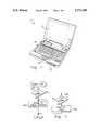
- FIG. 1illustrates a portable computer system including the power management capabilities of the present invention
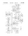
- FIG. 2is a block diagram of the computer system of FIG. 1;
- FIG. 3is a flowchart diagram illustrating operation of the power management software of the present invention cascading from the full-on state to the standby state to the suspend state;
- FIG. 4is a flowchart diagram illustrating operation of a resume event, which could be an RTC alarm causing the computer system to enter the suspend-to-disk state.
- the computer system 20includes a display screen 22, keyboard 24, track ball or mouse 26, and floppy drive 28.
- the computer systemincludes system management software which, based on varying periods of inactivity, causes the computer system to enter various reduced power states.
- a state referred to as “full on”indicates the computer system is operating normally without any power saving features, and all peripherals and devices are powered on.
- a state referred to as “standby”is a first stage in power management, wherein the hard disk is powered down with various of the components and peripherals either fully operational or executing with reduced power.
- a state referred to as "suspend”is a second power management stage where a greater number of components and peripherals are turned off or are subject to reduced power. In this stage, the hard disk remains powered off, backlighting is reduced to the display screen 22, the microprocessor speed is reduced, and various other peripherals are turned off or reduced.
- the third and last stage of power managementis referred to as the "suspend-to-disk” or S2D state. In this state, the power to the computer system is completely off, and thus no power is consumed by the computer system.
- a process referred to as “resume”causes a transition from one of the low power states, i.e., the standby state, suspend state, or S2D state, to the full on state.
- the computer systemincludes a central processing unit (CPU) 102 which is coupled through a CPU local bus 104 to a host/PCI/cache bridge 106.
- the bridge 106couples through a memory bus 108 to main memory 110.
- the host/PCI/cache bridge 106also interfaces to a peripheral component interconnect (PCI) bus 120.
- PCIperipheral component interconnect
- a PCI local busis used.
- VESAVideo Electronics Standards Association
- VLVideo Electronics Standards Association
- the computer systemmay or may not include a local bus, as desired.
- a video adapter 170 and video frame buffer 172are coupled to the PCI bus 120 for controlling video functions.
- a SCSI (small computer systems interface) controller or SCSI adapter 122is coupled to the PCI bus 120.
- the SCSI adapter 122includes a SCSI channel for connecting to various devices, such as a hard drive, a tape drive, etc.
- various other devicesmay be connected to the PCI bus 120, depending upon space requirements in the portable computer system.
- a network interface card 140connects to the PCI bus 120 which interfaces to a local area network (LAN) 142.
- LANlocal area network
- Expansion bus bridge logic 150is also preferably coupled to the PCI bus 120.
- the expansion bus bridge logic 150interfaces to an expansion bus 152.
- the expansion busmay be any of varying types, including the industry standard architecture (ISA) bus, also referred to as the AT bus, the extended industry standard architecture (EISA) bus, or the microchannel architecture (MCA) bus.
- ISAindustry standard architecture
- EISAextended industry standard architecture
- MCAmicrochannel architecture
- Various devicesmay be coupled to the expansion bus 152, including expansion bus memory 154 and a modem 156.
- the expansion bus bridge logic 150also couples to a peripheral expansion bus referred to as the X-bus 160.
- the X-bus 160is used for connecting various peripherals to the computer system.
- devices coupled to the X-bus 160include an interrupt system 162, a real time clock (RTC) 164, a direct memory access (DMA) system 166, ROM/Flash memory 168 and timers 169.
- RTCreal time clock
- DMAdirect memory access
- Other peripheralsare preferably connected to the X-bus 160, including communications ports, diagnostics ports, command/status registers, non-volatile static random access memory (NVSRAM), etc.
- NVSRAMnon-volatile static random access memory
- the computer systempreferably uses an Intel 486 low power chip set and also preferably uses the WD 8110 power control chip set from Western Digital Corporation.
- the Intel chip setsupports an interrupt referred to as the System Management Interrupt or SMI, which is a high priority interrupt used for power management functions.
- SMISystem Management Interrupt
- Various registersare associated with the SMI interrupt which indicate the power management functions that should be performed.
- the ROM/Plash memory 168preferably comprises BIOS (Basic Input/Output Services) software, and the power management or system management software is preferably comprised in the BIOS.
- BIOSBasic Input/Output Services
- the system management softwaremay be comprised in the main memory 110 or optionally in the keyboard controller, such as the Intel 8051 keyboard controller.
- the computer systemincludes several power management states, including a standby state, a suspend state, and a suspend-to-disk (S2D) state.
- a standby stateAs discussed above, the computer system includes several power management states, including a standby state, a suspend state, and a suspend-to-disk (S2D) state.
- S2Dsuspend-to-disk
- cascading from the suspend state to the zero volt suspend-to-disk stateis a very important power saving feature which provides greatly increased power savings over systems which do not cascade from the suspend state to the suspend-to-disk state.
- power managed computer systemsare restricted in their activities while in the suspend state.
- the timers 169In the suspend state, the timers 169 are not operational and thus these timers cannot be used to calculate the desired period of inactivity which indicates that the computer should cascade from the suspend state to the suspend to disk state.
- the system of the present inventionuses the real time clock (RTC) 164 as the timer for calculating the period of inactivity which directs the computer system to cascade from the suspend state to the suspend-to-disk state.
- RTCreal time clock
- Thisprovides a simple and convenient mechanism for cascading from the suspend state to the suspend-to-disk state even though the various chip set timers 169 are non-functional in the suspend state.
- the present inventionalso intelligently manages the alarm capability of the RTC 164 to not interfere with other application's use of the RTC.
- the system management software in the computer systemallows the user to input desired periods of inactivity which indicate when the computer system should cascade from the full-on state to the standby state, and from the standby state to the suspend state, and finally from the suspend state to the suspend-to-disk state.
- these time intervalscan be preset within the computer system, as desired.
- the computer systempreferably uses the chip set timers 169 in determining when to cascade from the full-on state to the standby state, and from the standby state to the suspend state.
- the computer systempreferably includes user programmable inactivity periods which determine when the computer system cascades from the full-on state to the standby state and then to the suspend state and finally to the suspend-to-disk state.
- an SMI interrupt for standby modeis asserted in step 304.
- the SMI interruptis an interrupt available in the Intel chip set which is used exclusively for power management functions.
- the SMI interruptis asserted and the SMI registers are loaded with values indicating that the computer system should cascade to the standby state.
- the computer systementers the standby state, i.e., the system management software turns off power to the hard drive and performs other functions to place the computer system in the standby state.
- an SMI interruptis generated in step 310 to cascade the computer system to the suspend state.
- the SMI interruptis generated and one or more registers are loaded with values indicating that the system management software should place the computer system in the suspend state.
- step 312the system management software examines the real time clock (RTC) alarm.
- RTCreal time clock
- the RTC 164can be set by user applications for various timing functions.
- the system management softwaredetermines if the RTC alarm is already set by an application and, if so, the period of time before the alarm is set to engage.
- the system management softwaredetermines if the RTC alarm is set by an application to expire before the time that the computer system would cascade to the suspend-to-disk state. If this is case, then operation proceeds from step 312 directly to step 320.
- the RTC alarmis already set by an application to expire before the suspend-to-disk inactivity time, and thus the RTC alarm cannot be set to the S2D time.
- step 314the system management software saves the state of the RTC alarm to memory 110.
- the system management softwarepreserves the state of the RTC alarm in case the alarm has been set by another application.
- step 316the system management software reprograms the RTC 164 to generate an alarm interrupt at the suspend-to-disk time, i.e., at the time when the user set period of inactivity has elapsed, indicating that the computer should cascade from the suspend state to the S2D state.
- step 318the system management software sets a flag to indicate that the RTC alarm is a S2D alarm.
- the RTC alarmwill trigger the system management software to cascade the computer system to the suspend-to-disk state.
- the system management softwarecauses the computer system to enter the suspend state. Therefore, if the RTC alarm has not been set by a user application to expire before the S2D time, the system management software uses the RTC as a trigger to cascade from the suspend state to the suspend-to-disk state.
- step 402the system management software determines if the resume event was an RTC alarm. If not, then the resume event was a "true" resume event, such as the user pressing a key on the keyboard 24 or providing another indication that the computer system is being actively used by the user. In this event, the system management software returns the computer system to normal operation in step 404.
- step 406the system management software determines whether the RTC alarm was an alarm to indicate a suspend-to-disk period of inactivity, i.e., whether the RTC alarm indicates that the computer system has been inactive for the user defined period of time to signify that the system should cascade from the suspend state to the suspend-to-disk state.
- the computer systemchecks the flag set in step 318 to determine whether the RTC alarm is a S2D alarm. If the flag is not set, i.e., the RTC alarm was not triggered by a period of inactivity corresponding to the suspend-to-disk state, then the system management software returns the computer system to normal operations in step 404.
- step 408the system management software causes the computer system to enter the suspend-to-disk state.
- the system management softwareremoves power completely from the computer system in the suspend-to-disk state, and thus the computer system does not consume any power or minimal power in this state.
- a system and method for enabling a computer system to cascade from a power managed suspend state to the suspend-to-disk stateis shown and described.
- the system and method of the present inventionis independent of operating system and thus can be adapted to various types of systems. Further, the ability to cascade to the suspend-to-disk state provides increased power savings over power managed computer systems which are unable to cascade to the suspend-to-disk state.
Landscapes
- Engineering & Computer Science (AREA)
- Theoretical Computer Science (AREA)
- Physics & Mathematics (AREA)
- General Engineering & Computer Science (AREA)
- General Physics & Mathematics (AREA)
- Power Sources (AREA)
Abstract
Description
Claims (7)
Priority Applications (1)
| Application Number | Priority Date | Filing Date | Title |
|---|---|---|---|
| US08/697,432US5771390A (en) | 1995-01-05 | 1996-08-23 | System and method for cascading from a power managed suspend state to a suspend-to-disk state in a computer system |
Applications Claiming Priority (2)
| Application Number | Priority Date | Filing Date | Title |
|---|---|---|---|
| US36901795A | 1995-01-05 | 1995-01-05 | |
| US08/697,432US5771390A (en) | 1995-01-05 | 1996-08-23 | System and method for cascading from a power managed suspend state to a suspend-to-disk state in a computer system |
Related Parent Applications (1)
| Application Number | Title | Priority Date | Filing Date |
|---|---|---|---|
| US36901795AContinuation | 1995-01-05 | 1995-01-05 |
Publications (1)
| Publication Number | Publication Date |
|---|---|
| US5771390Atrue US5771390A (en) | 1998-06-23 |
Family
ID=23453711
Family Applications (1)
| Application Number | Title | Priority Date | Filing Date |
|---|---|---|---|
| US08/697,432Expired - LifetimeUS5771390A (en) | 1995-01-05 | 1996-08-23 | System and method for cascading from a power managed suspend state to a suspend-to-disk state in a computer system |
Country Status (1)
| Country | Link |
|---|---|
| US (1) | US5771390A (en) |
Cited By (9)
| Publication number | Priority date | Publication date | Assignee | Title |
|---|---|---|---|---|
| US6065121A (en)* | 1998-03-31 | 2000-05-16 | Compaq Computer Corporation | Control of computer system wake/sleep transitions |
| US6408397B1 (en)* | 1999-05-24 | 2002-06-18 | Dell Usa, L.P. | Using RTC wake-up to enable recovery from power failures |
| US6691237B1 (en) | 2000-08-08 | 2004-02-10 | Dell Products, L.P. | Active memory pool management policies |
| US6879774B1 (en) | 2000-05-26 | 2005-04-12 | Dell Products L.P. | Content sensitive control of rotating media |
| US20060068855A1 (en)* | 2004-09-28 | 2006-03-30 | Fujitsu Limited | Cellular phone and operational mode switching method thereof |
| US20060284833A1 (en)* | 2005-06-15 | 2006-12-21 | Chi-Hsiung Lin | Portable electronic device capable of performing a function according to a sensing result of pressure |
| US20080028243A1 (en)* | 2006-07-26 | 2008-01-31 | Kabushiki Kaisha Toshiba | Information processing apparatus and a controlling method for an information processing apparatus |
| WO2015057572A3 (en)* | 2013-10-14 | 2015-06-11 | Nike Innovate C.V. | Adaptive timing configuration for athletic devices |
| CN109271010A (en)* | 2017-07-18 | 2019-01-25 | 技嘉科技股份有限公司 | RTC battery detection method and computer device using same |
Citations (5)
| Publication number | Priority date | Publication date | Assignee | Title |
|---|---|---|---|---|
| US5167024A (en)* | 1989-09-08 | 1992-11-24 | Apple Computer, Inc. | Power management for a laptop computer with slow and sleep modes |
| US5218704A (en)* | 1989-10-30 | 1993-06-08 | Texas Instruments | Real-time power conservation for portable computers |
| US5274797A (en)* | 1986-05-30 | 1993-12-28 | Bull Hn Information Systems Inc. | Multiprocessor system with centralized initialization, testing and monitoring of the system and providing centralized timing |
| US5396635A (en)* | 1990-06-01 | 1995-03-07 | Vadem Corporation | Power conservation apparatus having multiple power reduction levels dependent upon the activity of the computer system |
| US5423045A (en)* | 1992-04-15 | 1995-06-06 | International Business Machines Corporation | System for distributed power management in portable computers |
- 1996
- 1996-08-23USUS08/697,432patent/US5771390A/ennot_activeExpired - Lifetime
Patent Citations (5)
| Publication number | Priority date | Publication date | Assignee | Title |
|---|---|---|---|---|
| US5274797A (en)* | 1986-05-30 | 1993-12-28 | Bull Hn Information Systems Inc. | Multiprocessor system with centralized initialization, testing and monitoring of the system and providing centralized timing |
| US5167024A (en)* | 1989-09-08 | 1992-11-24 | Apple Computer, Inc. | Power management for a laptop computer with slow and sleep modes |
| US5218704A (en)* | 1989-10-30 | 1993-06-08 | Texas Instruments | Real-time power conservation for portable computers |
| US5396635A (en)* | 1990-06-01 | 1995-03-07 | Vadem Corporation | Power conservation apparatus having multiple power reduction levels dependent upon the activity of the computer system |
| US5423045A (en)* | 1992-04-15 | 1995-06-06 | International Business Machines Corporation | System for distributed power management in portable computers |
Cited By (15)
| Publication number | Priority date | Publication date | Assignee | Title |
|---|---|---|---|---|
| US6065121A (en)* | 1998-03-31 | 2000-05-16 | Compaq Computer Corporation | Control of computer system wake/sleep transitions |
| US6408397B1 (en)* | 1999-05-24 | 2002-06-18 | Dell Usa, L.P. | Using RTC wake-up to enable recovery from power failures |
| US6879774B1 (en) | 2000-05-26 | 2005-04-12 | Dell Products L.P. | Content sensitive control of rotating media |
| US7216197B2 (en) | 2000-08-08 | 2007-05-08 | Dell Products L.P. | System and method for adjusting pooling of system memory in reponse to changes in monitored data processor activity |
| US6691237B1 (en) | 2000-08-08 | 2004-02-10 | Dell Products, L.P. | Active memory pool management policies |
| US20040093460A1 (en)* | 2000-08-08 | 2004-05-13 | Dell Products | System and method for adjusting polling of system memory in reponse to changes in monitored data processor activity |
| US7523326B2 (en)* | 2004-09-28 | 2009-04-21 | Fujitsu Limited | Method and apparatus for maintaining a suspension state after powering down and fully powering down upon expiration of a timer or low battery level |
| US20060068855A1 (en)* | 2004-09-28 | 2006-03-30 | Fujitsu Limited | Cellular phone and operational mode switching method thereof |
| US20060284833A1 (en)* | 2005-06-15 | 2006-12-21 | Chi-Hsiung Lin | Portable electronic device capable of performing a function according to a sensing result of pressure |
| US20080028243A1 (en)* | 2006-07-26 | 2008-01-31 | Kabushiki Kaisha Toshiba | Information processing apparatus and a controlling method for an information processing apparatus |
| WO2015057572A3 (en)* | 2013-10-14 | 2015-06-11 | Nike Innovate C.V. | Adaptive timing configuration for athletic devices |
| CN105745589A (en)* | 2013-10-14 | 2016-07-06 | 耐克创新有限合伙公司 | Adaptive timing configuration for athletic devices |
| US10025274B2 (en) | 2013-10-14 | 2018-07-17 | Nike, Inc. | Adaptive timing configuration for athletic devices |
| CN105745589B (en)* | 2013-10-14 | 2019-10-18 | 耐克创新有限合伙公司 | The device and method that adaptability timing for sports equipment configures |
| CN109271010A (en)* | 2017-07-18 | 2019-01-25 | 技嘉科技股份有限公司 | RTC battery detection method and computer device using same |
Similar Documents
| Publication | Publication Date | Title |
|---|---|---|
| US5630143A (en) | Microprocessor with externally controllable power management | |
| US7900076B2 (en) | Power management method for a pipelined computer system | |
| KR100229575B1 (en) | Information processing system | |
| US6193422B1 (en) | Implementation of idle mode in a suspend/resume microprocessor system | |
| US5355501A (en) | Idle detection system | |
| US5446906A (en) | Method and apparatus for suspending and resuming a keyboard controller | |
| US6092209A (en) | Method and apparatus for managing power consumption of peripheral devices of personal computers | |
| US6243831B1 (en) | Computer system with power loss protection mechanism | |
| US5632037A (en) | Microprocessor having power management circuitry with coprocessor support | |
| US5535400A (en) | SCSI disk drive power down apparatus | |
| JPH0850523A (en) | Method and equipment for management of power consumption in computer system | |
| US5515539A (en) | Apparatus and method for reducing power consumption by peripheral devices after downloading a program therefrom | |
| JPH08314587A (en) | Power saving power source circuit | |
| US5220671A (en) | Low-power consuming information processing apparatus | |
| US7869835B1 (en) | Method and system for pre-loading and executing computer instructions within the cache memory | |
| US5771390A (en) | System and method for cascading from a power managed suspend state to a suspend-to-disk state in a computer system | |
| EP0828212B1 (en) | Microprocessor with hardware controlled power management and selectable input/output control pins and method therefor | |
| US5375209A (en) | Microprocessor for selectively configuring pinout by activating tri-state device to disable internal clock from external pin | |
| US20060080561A1 (en) | Information handling system having reduced power consumption | |
| JP2000305673A (en) | Method and device for managing power consumption | |
| JPH075959A (en) | Method and apparatus for increasing or decreasing of power of peripheral device |
Legal Events
| Date | Code | Title | Description |
|---|---|---|---|
| STCF | Information on status: patent grant | Free format text:PATENTED CASE | |
| FEPP | Fee payment procedure | Free format text:PAYOR NUMBER ASSIGNED (ORIGINAL EVENT CODE: ASPN); ENTITY STATUS OF PATENT OWNER: LARGE ENTITY | |
| FPAY | Fee payment | Year of fee payment:4 | |
| REMI | Maintenance fee reminder mailed | ||
| FPAY | Fee payment | Year of fee payment:8 | |
| FPAY | Fee payment | Year of fee payment:12 | |
| AS | Assignment | Owner name:BANK OF AMERICA, N.A., AS ADMINISTRATIVE AGENT, TE Free format text:PATENT SECURITY AGREEMENT (ABL);ASSIGNORS:DELL INC.;APPASSURE SOFTWARE, INC.;ASAP SOFTWARE EXPRESS, INC.;AND OTHERS;REEL/FRAME:031898/0001 Effective date:20131029 Owner name:BANK OF NEW YORK MELLON TRUST COMPANY, N.A., AS FIRST LIEN COLLATERAL AGENT, TEXAS Free format text:PATENT SECURITY AGREEMENT (NOTES);ASSIGNORS:APPASSURE SOFTWARE, INC.;ASAP SOFTWARE EXPRESS, INC.;BOOMI, INC.;AND OTHERS;REEL/FRAME:031897/0348 Effective date:20131029 Owner name:BANK OF AMERICA, N.A., AS COLLATERAL AGENT, NORTH CAROLINA Free format text:PATENT SECURITY AGREEMENT (TERM LOAN);ASSIGNORS:DELL INC.;APPASSURE SOFTWARE, INC.;ASAP SOFTWARE EXPRESS, INC.;AND OTHERS;REEL/FRAME:031899/0261 Effective date:20131029 Owner name:BANK OF AMERICA, N.A., AS ADMINISTRATIVE AGENT, TEXAS Free format text:PATENT SECURITY AGREEMENT (ABL);ASSIGNORS:DELL INC.;APPASSURE SOFTWARE, INC.;ASAP SOFTWARE EXPRESS, INC.;AND OTHERS;REEL/FRAME:031898/0001 Effective date:20131029 Owner name:BANK OF NEW YORK MELLON TRUST COMPANY, N.A., AS FI Free format text:PATENT SECURITY AGREEMENT (NOTES);ASSIGNORS:APPASSURE SOFTWARE, INC.;ASAP SOFTWARE EXPRESS, INC.;BOOMI, INC.;AND OTHERS;REEL/FRAME:031897/0348 Effective date:20131029 Owner name:BANK OF AMERICA, N.A., AS COLLATERAL AGENT, NORTH Free format text:PATENT SECURITY AGREEMENT (TERM LOAN);ASSIGNORS:DELL INC.;APPASSURE SOFTWARE, INC.;ASAP SOFTWARE EXPRESS, INC.;AND OTHERS;REEL/FRAME:031899/0261 Effective date:20131029 | |
| AS | Assignment | Owner name:SECUREWORKS, INC., GEORGIA Free format text:RELEASE BY SECURED PARTY;ASSIGNOR:BANK OF AMERICA, N.A., AS ADMINISTRATIVE AGENT;REEL/FRAME:040065/0216 Effective date:20160907 Owner name:DELL USA L.P., TEXAS Free format text:RELEASE BY SECURED PARTY;ASSIGNOR:BANK OF AMERICA, N.A., AS ADMINISTRATIVE AGENT;REEL/FRAME:040065/0216 Effective date:20160907 Owner name:DELL SOFTWARE INC., CALIFORNIA Free format text:RELEASE BY SECURED PARTY;ASSIGNOR:BANK OF AMERICA, N.A., AS ADMINISTRATIVE AGENT;REEL/FRAME:040065/0216 Effective date:20160907 Owner name:WYSE TECHNOLOGY L.L.C., CALIFORNIA Free format text:RELEASE BY SECURED PARTY;ASSIGNOR:BANK OF AMERICA, N.A., AS ADMINISTRATIVE AGENT;REEL/FRAME:040065/0216 Effective date:20160907 Owner name:COMPELLANT TECHNOLOGIES, INC., MINNESOTA Free format text:RELEASE BY SECURED PARTY;ASSIGNOR:BANK OF AMERICA, N.A., AS ADMINISTRATIVE AGENT;REEL/FRAME:040065/0216 Effective date:20160907 Owner name:FORCE10 NETWORKS, INC., CALIFORNIA Free format text:RELEASE BY SECURED PARTY;ASSIGNOR:BANK OF AMERICA, N.A., AS ADMINISTRATIVE AGENT;REEL/FRAME:040065/0216 Effective date:20160907 Owner name:DELL PRODUCTS L.P., TEXAS Free format text:RELEASE BY SECURED PARTY;ASSIGNOR:BANK OF AMERICA, N.A., AS ADMINISTRATIVE AGENT;REEL/FRAME:040065/0216 Effective date:20160907 Owner name:CREDANT TECHNOLOGIES, INC., TEXAS Free format text:RELEASE BY SECURED PARTY;ASSIGNOR:BANK OF AMERICA, N.A., AS ADMINISTRATIVE AGENT;REEL/FRAME:040065/0216 Effective date:20160907 Owner name:PEROT SYSTEMS CORPORATION, TEXAS Free format text:RELEASE BY SECURED PARTY;ASSIGNOR:BANK OF AMERICA, N.A., AS ADMINISTRATIVE AGENT;REEL/FRAME:040065/0216 Effective date:20160907 Owner name:APPASSURE SOFTWARE, INC., VIRGINIA Free format text:RELEASE BY SECURED PARTY;ASSIGNOR:BANK OF AMERICA, N.A., AS ADMINISTRATIVE AGENT;REEL/FRAME:040065/0216 Effective date:20160907 Owner name:DELL MARKETING L.P., TEXAS Free format text:RELEASE BY SECURED PARTY;ASSIGNOR:BANK OF AMERICA, N.A., AS ADMINISTRATIVE AGENT;REEL/FRAME:040065/0216 Effective date:20160907 Owner name:ASAP SOFTWARE EXPRESS, INC., ILLINOIS Free format text:RELEASE BY SECURED PARTY;ASSIGNOR:BANK OF AMERICA, N.A., AS ADMINISTRATIVE AGENT;REEL/FRAME:040065/0216 Effective date:20160907 Owner name:DELL INC., TEXAS Free format text:RELEASE BY SECURED PARTY;ASSIGNOR:BANK OF AMERICA, N.A., AS ADMINISTRATIVE AGENT;REEL/FRAME:040065/0216 Effective date:20160907 | |
| AS | Assignment | Owner name:DELL USA L.P., TEXAS Free format text:RELEASE BY SECURED PARTY;ASSIGNOR:BANK OF AMERICA, N.A., AS COLLATERAL AGENT;REEL/FRAME:040040/0001 Effective date:20160907 Owner name:SECUREWORKS, INC., GEORGIA Free format text:RELEASE BY SECURED PARTY;ASSIGNOR:BANK OF AMERICA, N.A., AS COLLATERAL AGENT;REEL/FRAME:040040/0001 Effective date:20160907 Owner name:DELL SOFTWARE INC., CALIFORNIA Free format text:RELEASE BY SECURED PARTY;ASSIGNOR:BANK OF AMERICA, N.A., AS COLLATERAL AGENT;REEL/FRAME:040040/0001 Effective date:20160907 Owner name:COMPELLENT TECHNOLOGIES, INC., MINNESOTA Free format text:RELEASE BY SECURED PARTY;ASSIGNOR:BANK OF AMERICA, N.A., AS COLLATERAL AGENT;REEL/FRAME:040040/0001 Effective date:20160907 Owner name:DELL MARKETING L.P., TEXAS Free format text:RELEASE BY SECURED PARTY;ASSIGNOR:BANK OF AMERICA, N.A., AS COLLATERAL AGENT;REEL/FRAME:040040/0001 Effective date:20160907 Owner name:WYSE TECHNOLOGY L.L.C., CALIFORNIA Free format text:RELEASE BY SECURED PARTY;ASSIGNOR:BANK OF AMERICA, N.A., AS COLLATERAL AGENT;REEL/FRAME:040040/0001 Effective date:20160907 Owner name:CREDANT TECHNOLOGIES, INC., TEXAS Free format text:RELEASE BY SECURED PARTY;ASSIGNOR:BANK OF AMERICA, N.A., AS COLLATERAL AGENT;REEL/FRAME:040040/0001 Effective date:20160907 Owner name:FORCE10 NETWORKS, INC., CALIFORNIA Free format text:RELEASE BY SECURED PARTY;ASSIGNOR:BANK OF AMERICA, N.A., AS COLLATERAL AGENT;REEL/FRAME:040040/0001 Effective date:20160907 Owner name:DELL INC., TEXAS Free format text:RELEASE BY SECURED PARTY;ASSIGNOR:BANK OF AMERICA, N.A., AS COLLATERAL AGENT;REEL/FRAME:040040/0001 Effective date:20160907 Owner name:DELL PRODUCTS L.P., TEXAS Free format text:RELEASE BY SECURED PARTY;ASSIGNOR:BANK OF AMERICA, N.A., AS COLLATERAL AGENT;REEL/FRAME:040040/0001 Effective date:20160907 Owner name:APPASSURE SOFTWARE, INC., VIRGINIA Free format text:RELEASE BY SECURED PARTY;ASSIGNOR:BANK OF AMERICA, N.A., AS COLLATERAL AGENT;REEL/FRAME:040040/0001 Effective date:20160907 Owner name:PEROT SYSTEMS CORPORATION, TEXAS Free format text:RELEASE BY SECURED PARTY;ASSIGNOR:BANK OF AMERICA, N.A., AS COLLATERAL AGENT;REEL/FRAME:040040/0001 Effective date:20160907 Owner name:ASAP SOFTWARE EXPRESS, INC., ILLINOIS Free format text:RELEASE BY SECURED PARTY;ASSIGNOR:BANK OF AMERICA, N.A., AS COLLATERAL AGENT;REEL/FRAME:040040/0001 Effective date:20160907 Owner name:PEROT SYSTEMS CORPORATION, TEXAS Free format text:RELEASE BY SECURED PARTY;ASSIGNOR:BANK OF NEW YORK MELLON TRUST COMPANY, N.A., AS COLLATERAL AGENT;REEL/FRAME:040065/0618 Effective date:20160907 Owner name:DELL PRODUCTS L.P., TEXAS Free format text:RELEASE BY SECURED PARTY;ASSIGNOR:BANK OF NEW YORK MELLON TRUST COMPANY, N.A., AS COLLATERAL AGENT;REEL/FRAME:040065/0618 Effective date:20160907 Owner name:DELL USA L.P., TEXAS Free format text:RELEASE BY SECURED PARTY;ASSIGNOR:BANK OF NEW YORK MELLON TRUST COMPANY, N.A., AS COLLATERAL AGENT;REEL/FRAME:040065/0618 Effective date:20160907 Owner name:FORCE10 NETWORKS, INC., CALIFORNIA Free format text:RELEASE BY SECURED PARTY;ASSIGNOR:BANK OF NEW YORK MELLON TRUST COMPANY, N.A., AS COLLATERAL AGENT;REEL/FRAME:040065/0618 Effective date:20160907 Owner name:APPASSURE SOFTWARE, INC., VIRGINIA Free format text:RELEASE BY SECURED PARTY;ASSIGNOR:BANK OF NEW YORK MELLON TRUST COMPANY, N.A., AS COLLATERAL AGENT;REEL/FRAME:040065/0618 Effective date:20160907 Owner name:SECUREWORKS, INC., GEORGIA Free format text:RELEASE BY SECURED PARTY;ASSIGNOR:BANK OF NEW YORK MELLON TRUST COMPANY, N.A., AS COLLATERAL AGENT;REEL/FRAME:040065/0618 Effective date:20160907 Owner name:COMPELLENT TECHNOLOGIES, INC., MINNESOTA Free format text:RELEASE BY SECURED PARTY;ASSIGNOR:BANK OF NEW YORK MELLON TRUST COMPANY, N.A., AS COLLATERAL AGENT;REEL/FRAME:040065/0618 Effective date:20160907 Owner name:WYSE TECHNOLOGY L.L.C., CALIFORNIA Free format text:RELEASE BY SECURED PARTY;ASSIGNOR:BANK OF NEW YORK MELLON TRUST COMPANY, N.A., AS COLLATERAL AGENT;REEL/FRAME:040065/0618 Effective date:20160907 Owner name:DELL MARKETING L.P., TEXAS Free format text:RELEASE BY SECURED PARTY;ASSIGNOR:BANK OF NEW YORK MELLON TRUST COMPANY, N.A., AS COLLATERAL AGENT;REEL/FRAME:040065/0618 Effective date:20160907 Owner name:ASAP SOFTWARE EXPRESS, INC., ILLINOIS Free format text:RELEASE BY SECURED PARTY;ASSIGNOR:BANK OF NEW YORK MELLON TRUST COMPANY, N.A., AS COLLATERAL AGENT;REEL/FRAME:040065/0618 Effective date:20160907 Owner name:CREDANT TECHNOLOGIES, INC., TEXAS Free format text:RELEASE BY SECURED PARTY;ASSIGNOR:BANK OF NEW YORK MELLON TRUST COMPANY, N.A., AS COLLATERAL AGENT;REEL/FRAME:040065/0618 Effective date:20160907 Owner name:DELL INC., TEXAS Free format text:RELEASE BY SECURED PARTY;ASSIGNOR:BANK OF NEW YORK MELLON TRUST COMPANY, N.A., AS COLLATERAL AGENT;REEL/FRAME:040065/0618 Effective date:20160907 Owner name:DELL SOFTWARE INC., CALIFORNIA Free format text:RELEASE BY SECURED PARTY;ASSIGNOR:BANK OF NEW YORK MELLON TRUST COMPANY, N.A., AS COLLATERAL AGENT;REEL/FRAME:040065/0618 Effective date:20160907 |