US5770996A - Transformer system for power line communications - Google Patents
Transformer system for power line communicationsDownload PDFInfo
- Publication number
- US5770996A US5770996AUS08/705,802US70580296AUS5770996AUS 5770996 AUS5770996 AUS 5770996AUS 70580296 AUS70580296 AUS 70580296AUS 5770996 AUS5770996 AUS 5770996A
- Authority
- US
- United States
- Prior art keywords
- transformer
- power line
- control panel
- secondary winding
- primary winding
- Prior art date
- Legal status (The legal status is an assumption and is not a legal conclusion. Google has not performed a legal analysis and makes no representation as to the accuracy of the status listed.)
- Expired - Lifetime
Links
- 238000004891communicationMethods0.000titleclaimsabstractdescription33
- 239000003990capacitorSubstances0.000claimsabstractdescription18
- 238000004804windingMethods0.000claimsdescription34
- 230000008878couplingEffects0.000claimsdescription7
- 238000010168coupling processMethods0.000claimsdescription7
- 238000005859coupling reactionMethods0.000claimsdescription7
- 230000005540biological transmissionEffects0.000description7
- 238000010586diagramMethods0.000description4
- 230000004913activationEffects0.000description2
- 230000008030eliminationEffects0.000description2
- 238000003379elimination reactionMethods0.000description2
- 238000005516engineering processMethods0.000description2
- 230000002452interceptive effectEffects0.000description2
- 238000012544monitoring processMethods0.000description2
- 241000269400SirenidaeSpecies0.000description1
- 230000008867communication pathwayEffects0.000description1
- 230000003750conditioning effectEffects0.000description1
- 230000004044responseEffects0.000description1
- 239000000779smokeSubstances0.000description1
- 230000001360synchronised effectEffects0.000description1
- 230000000007visual effectEffects0.000description1
Images


Classifications
- H—ELECTRICITY
- H04—ELECTRIC COMMUNICATION TECHNIQUE
- H04B—TRANSMISSION
- H04B3/00—Line transmission systems
- H04B3/54—Systems for transmission via power distribution lines
- H04B3/56—Circuits for coupling, blocking, or by-passing of signals
- H—ELECTRICITY
- H04—ELECTRIC COMMUNICATION TECHNIQUE
- H04B—TRANSMISSION
- H04B2203/00—Indexing scheme relating to line transmission systems
- H04B2203/54—Aspects of powerline communications not already covered by H04B3/54 and its subgroups
- H04B2203/5404—Methods of transmitting or receiving signals via power distribution lines
- H04B2203/542—Methods of transmitting or receiving signals via power distribution lines using zero crossing information
- H—ELECTRICITY
- H04—ELECTRIC COMMUNICATION TECHNIQUE
- H04B—TRANSMISSION
- H04B2203/00—Indexing scheme relating to line transmission systems
- H04B2203/54—Aspects of powerline communications not already covered by H04B3/54 and its subgroups
- H04B2203/5429—Applications for powerline communications
- H04B2203/5445—Local network
- H—ELECTRICITY
- H04—ELECTRIC COMMUNICATION TECHNIQUE
- H04B—TRANSMISSION
- H04B2203/00—Indexing scheme relating to line transmission systems
- H04B2203/54—Aspects of powerline communications not already covered by H04B3/54 and its subgroups
- H04B2203/5429—Applications for powerline communications
- H04B2203/5458—Monitor sensor; Alarm systems
- H—ELECTRICITY
- H04—ELECTRIC COMMUNICATION TECHNIQUE
- H04B—TRANSMISSION
- H04B2203/00—Indexing scheme relating to line transmission systems
- H04B2203/54—Aspects of powerline communications not already covered by H04B3/54 and its subgroups
- H04B2203/5462—Systems for power line communications
- H04B2203/5483—Systems for power line communications using coupling circuits
- H—ELECTRICITY
- H04—ELECTRIC COMMUNICATION TECHNIQUE
- H04B—TRANSMISSION
- H04B2203/00—Indexing scheme relating to line transmission systems
- H04B2203/54—Aspects of powerline communications not already covered by H04B3/54 and its subgroups
- H04B2203/5462—Systems for power line communications
- H04B2203/5491—Systems for power line communications using filtering and bypassing
Definitions
- the present inventionrelates to a transformer system for power line communications.
- Power line communication systemsexploit the existing power line wiring in a home or other facility for communication purposes.
- the local power line in a typical U.S. home or businesssupplies 110 volt AC, 60 Hz power.
- Other countrieshave similar systems that supply power at various voltage and frequency levels.
- the existing power line wiringmay be used for transmitting information within the home or business, thereby eliminating the need for additional wiring.
- the security systemincludes a plurality of sensors, controls, and alarms positioned in and around an area to be protected.
- One or more of these devicesmay be connected with the local power line through a standard wall plug or other connector.
- a control panelis also connected to the local power line through a standard plug or other connector.
- the power linesupplies power to the control panel. Also, the power line is used to send information from the control panel to one or more of the devices connected to the power line.
- a transformer systemmay be used to couple the control panel with the power line.
- the transformerisolates the power line from the control panel and conditions the power on the power line for use by the control panel.
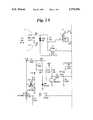
- FIG. 1One example of a power line coupling transformer system is shown in FIG. 1.
- An AC power line 2is coupled with the primary winding of first transformer, T1, to provide power to a control panel (not shown).
- the control panelis connected with the transformer system by lines 8A-8D.
- Transformer T1is rated at 10 volt-amps.
- a power conditioning circuit 6converts the AC power to about 8 volts DC, which is transmitted to the control panel by lines 8A, 8B.
- a signal generator 10receives serial data from the control panel on line 8D and, with associated circuitry, generates a frequency-modulated signal which is placed on the secondary winding of transformer T2. The signal is transferred to the primary winding of transformer T2, which is connected with power line 2. There is no circuitry for receiving an information signal from power line 2 and sending the signal to the control panel.
- Line 8Cprovides an AC signal to the control panel for synchronization.
- transformer systemssuch as the transformer system shown in FIG. 1, have several limitations.
- the connection between the control panel and transformer systemrequires four lines or wires.
- the wiresare typically exposed, e.g., along a wall. Therefore, there is a risk of damaging or disabling the security system by damaging one or more of the four wires, as well as the cost of stringing four wires.
- transformer T1 as shown in FIG. 1may be restricted to 10 volt-amps due to the size and weight of the associated circuitry, when it may be desirable to have a larger transformer, e.g., 40-50 volt-amps.
- the circuitryalso increases the cost of the coupling transformer system.
- coupling transformer systemssuch as the one shown in FIG. 1, allow only one-way communication from the control panel to the other devices.
- the coupling transformer systemssupport only one communication protocol.
- a power line communication transformer systemincludes a first transformer having a primary winding connected with a power line and a secondary winding connected with a communication device.
- the communication deviceis a control panel for a security system.
- a second transformerhas a primary winding connected in series with the primary winding of the first transformer and a secondary winding connected in parallel with the secondary winding of the first transformer.
- a first capacitoris connected in series with the secondary winding of the second transformer and in parallel with the secondary winding of the first transformer.
- a second capacitoris connected in series with the primary winding of the second transformer and in parallel with the primary winding of the first transformer.
- the communication devicesends and receives signals at a first frequency range, and the power line transmits power at a second frequency.
- the values of the first and second capacitorsare selected so that the second transformer provides a low impedance path at the first frequency range and a high impedance path at the second frequency.
- a fusemay be connected in series with the secondary winding of the first transformer.
- the present inventionprovides several advantages.
- the present inventionprovides a transformer system that is flexible, supporting different communication protocols.
- the present inventionallows for larger transformers to be used without increasing the overall size and weight of the transformer system.
- the transformer system of the present inventionis less expensive due to the elimination of complex circuitry and associated circuit components.
- the present inventionrequires only two wires for connection with the control panel, reducing cost and exposure to damage.
- FIG. 1shows a diagram of a transformer system
- FIG. 2shows a diagram of a local security system
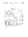
- FIG. 3shows a diagram of a transformer system according to the present invention.
- FIG. 2A diagram of a security system that uses a power line for communication is shown in FIG. 2.
- An areae.g., a home, has a local power line 20 that is coupled to a supply power line 22 at junction 24.
- the security systemalso may be located in a variety of facilities, e.g., businesses, warehouses, etc.
- the sensors 26are positioned throughout areas to be monitored.
- the sensors 26may be one of a wide variety of known sensors, including motion detectors, door/ window sensors, smoke detectors, and heat detectors.
- one or more alarm devices 28, e.g., sirensare also positioned in or near the monitored area.
- one or more controls 30, e.g., a light switch controlmay also be positioned in the area.
- Each of the above-described devicesare connected to the local power line through standard two-prong (or three-prong) wall plugs or other connectors.
- One or more control panels 32are also connected to the local power line 20 through a wall plug.
- a control panel 32allows the users of the security system to program the system and activate/deactivate the system.
- control panel 32monitors the sensors 26 in the system and receives a signal when a sensor is activated. The control panel may then activate one or more local alarm devices 28 (e.g., siren, voice, visual) and/or transmit the sensor information to a remote agency, e.g., fire department, police, or monitoring station. The remote transmission may be by phone or wireless communication.
- control panel 32may be used to activate one or more controls 30, e.g., to turn on/off a light or activate a sound recording. The activation of controls 30 may be part of the response to a sensor activation or independent of the sensors.
- X-10 Code FormatOne known protocol, which we will refer to as the "X-10 Code Format," was developed by Pico Electronics Ltd. of Fife, Scotland, and is used by X-10 Home Controls Inc. of Northvail, N.J. This format is disclosed in U.S. Pat. Nos. 4,200,862; 4,628,440; and 4,638,299, all of which are incorporated herein by reference.
- transmissionsare synchronized to the zero-crossing point of the AC signal on local power line 20.
- a binary "1"is represented by a 1 msec burst of 120 kHz and a binary "0" is represented by the absence of a 120 kHz burst.
- a 10K baud, frequency-modulated signalis used.
- a binary "1”is represented by 270 kHz frequency signal and a binary "0” is represented by a 235 kHz frequency signal.
- a start sequenceis used for each transmission, consisting of 800 msec of a logical "1", 700 msec of a logical "0", and 100 msec of a logical "1".
- the first byteis a house (or facility) code.
- the second byteis a siren control.
- the third bitis an arming level and nibblewise checksum.
- the fourth byteis a bytewise checksum. All bytes are transmitted with the most significant bit first.
- the total time for a transmissionis about 4.8 msec.
- the transmissionsshould be centered about the zero-crossing on the AC signal.
- CEConsumer Electronics
- a transformer system 40couples the control panel 32 with power line 20, as shown in FIG. 3.
- Transformer system 40includes two transformers, 42, 44, respectively.
- Transformer 42is a step-down transformer that steps down the voltage on power line 20 to a lower voltage level, suitable for supplying power to control panel 32. For example, in a typical U.S. system, the 110 volt AC signal is stepped down to a 9 volt or 16 volt signal.
- a rectifying circuit(not shown), such as a bridge rectifier circuit, is associated with control panel 32 to convert the stepped-down 9 or 16 volt signal to a DC signal.
- Transformer 44provides the communication pathway for communication transmissions between control panel 32 and security system devices 26, 28, and 30 on power line 20.
- the primary-to-secondary turns ratio in transformer 44is 1:1.
- the secondary winding 46 of transformer 44is connected in parallel with the secondary winding 48 of transformer 42.
- the primary winding 50 of transformer 44is connected in series with the primary winding 52 of transformer 42.
- a first capacitor 54is connected in series with the secondary winding 46 of transformer 44 and in parallel with the secondary winding 48 of transformer 42.
- a second capacitor 56is connected in series with primary winding 50 of transformer 44 and in parallel with primary winding 52 of transformer 42.
- a fuse 58 or other circuit-breaking devicemay be connected in series with secondary windings 46 and 48 to prevent surges in the power line signal from damaging control panel 32.
- transformer 44provides the power line coupling for the communication signals and transformer 42 provides the coupling for the power supplied to control panel 32.
- capacitors 54 and 56are selected so that transformer system 40 will enable two-way communications of both the X-10 Code Format and the Interactive Technologies protocol (and any other protocol that operates within about 100 kHz to about 270 kHz).
- capacitor 54is selected to have a capacitance of 2.2 ⁇ F and capacitor 56 is selected to have a capacitance of 0.10 ⁇ F.
- transformer system 40supports multiple communication protocols. Once the frequency range for the communication protocol is determined, capacitors 54, 56 are selected to provide a relatively low impedance path for the communication signals through transformer 44. At the power line frequency, capacitors 54, 56 provide a high impedance path through transformer 44. Therefore, the power line signal is directed through transformer 42 to supply energy to control panel 32.
- transformer system 40includes transformers 42, 44 and capacitors 54, 56; no other local circuitry is required. Therefore, larger transformers 42, 44 may be used.
- transformer system 40also reduces the overall cost of system 40. Also, only two wires are needed to connect transformer system 40 with control panel 32, reducing cost, complexity, and other problems associated with stringing multiple wires between the wall plug and control panel.
Landscapes
- Engineering & Computer Science (AREA)
- Power Engineering (AREA)
- Computer Networks & Wireless Communication (AREA)
- Signal Processing (AREA)
- Cable Transmission Systems, Equalization Of Radio And Reduction Of Echo (AREA)
Abstract
Description
Claims (8)
Priority Applications (1)
| Application Number | Priority Date | Filing Date | Title |
|---|---|---|---|
| US08/705,802US5770996A (en) | 1996-08-30 | 1996-08-30 | Transformer system for power line communications |
Applications Claiming Priority (1)
| Application Number | Priority Date | Filing Date | Title |
|---|---|---|---|
| US08/705,802US5770996A (en) | 1996-08-30 | 1996-08-30 | Transformer system for power line communications |
Publications (1)
| Publication Number | Publication Date |
|---|---|
| US5770996Atrue US5770996A (en) | 1998-06-23 |
Family
ID=24835011
Family Applications (1)
| Application Number | Title | Priority Date | Filing Date |
|---|---|---|---|
| US08/705,802Expired - LifetimeUS5770996A (en) | 1996-08-30 | 1996-08-30 | Transformer system for power line communications |
Country Status (1)
| Country | Link |
|---|---|
| US (1) | US5770996A (en) |
Cited By (48)
| Publication number | Priority date | Publication date | Assignee | Title |
|---|---|---|---|---|
| US5937342A (en)* | 1997-01-28 | 1999-08-10 | Dynamic Telecommunications, Inc. | Wireless local distribution system using standard power lines |
| WO2000079697A1 (en)* | 1999-06-18 | 2000-12-28 | Dynamic Telecommunications, Inc. | Wireless local distribution system using standard power lines |
| US6243571B1 (en)* | 1998-09-21 | 2001-06-05 | Phonex Corporation | Method and system for distribution of wireless signals for increased wireless coverage using power lines |
| US20010054953A1 (en)* | 2000-04-14 | 2001-12-27 | Kline Paul A. | Digital communications utilizing medium voltage power distribution lines |
| US20020002040A1 (en)* | 2000-04-19 | 2002-01-03 | Kline Paul A. | Method and apparatus for interfacing RF signals to medium voltage power lines |
| US20020118101A1 (en)* | 2001-02-14 | 2002-08-29 | Kline Paul A. | Data communication over a power line |
| US20020163430A1 (en)* | 2001-05-01 | 2002-11-07 | Bergman John Todd | Wireless phone-interface device |
| US6483203B1 (en)* | 2000-06-08 | 2002-11-19 | 3Com Corporation | Single unit integrated transformer assembly |
| US6496104B2 (en) | 2000-03-15 | 2002-12-17 | Current Technologies, L.L.C. | System and method for communication via power lines using ultra-short pulses |
| US6563420B2 (en)* | 2001-09-13 | 2003-05-13 | Square D Company | Power line communications apparatus and method |
| US20040056734A1 (en)* | 2001-05-18 | 2004-03-25 | Davidow Clifford A. | Medium voltage signal coupling structure for last leg power grid high-speed data network |
| US6950567B2 (en) | 2001-02-14 | 2005-09-27 | Current Technologies, Llc | Method and apparatus for providing inductive coupling and decoupling of high-frequency, high-bandwidth data signals directly on and off of a high voltage power line |
| US6965303B2 (en) | 2002-12-10 | 2005-11-15 | Current Technologies, Llc | Power line communication system and method |
| US6965302B2 (en) | 2000-04-14 | 2005-11-15 | Current Technologies, Llc | Power line communication system and method of using the same |
| US6977578B2 (en) | 2000-01-20 | 2005-12-20 | Current Technologies, Llc | Method of isolating data in a power line communications network |
| US6980090B2 (en) | 2002-12-10 | 2005-12-27 | Current Technologies, Llc | Device and method for coupling with electrical distribution network infrastructure to provide communications |
| US6980089B1 (en) | 2000-08-09 | 2005-12-27 | Current Technologies, Llc | Non-intrusive coupling to shielded power cable |
| US6980091B2 (en) | 2002-12-10 | 2005-12-27 | Current Technologies, Llc | Power line communication system and method of operating the same |
| US6982611B2 (en) | 2002-06-24 | 2006-01-03 | Current Technologies, Llc | Power line coupling device and method of using the same |
| US6998962B2 (en) | 2000-04-14 | 2006-02-14 | Current Technologies, Llc | Power line communication apparatus and method of using the same |
| US20060071649A1 (en)* | 2004-09-30 | 2006-04-06 | Gerhard Schrom | Apparatus and method for multi-phase transformers |
| US7046124B2 (en) | 2003-01-21 | 2006-05-16 | Current Technologies, Llc | Power line coupling device and method of using the same |
| US7054414B2 (en) | 2001-05-01 | 2006-05-30 | Interactive Technologies Inc. | Wireless phone-interface device |
| US7053756B2 (en) | 2001-12-21 | 2006-05-30 | Current Technologies, Llc | Facilitating communication of data signals on electric power systems |
| US20060125609A1 (en)* | 2000-08-09 | 2006-06-15 | Kline Paul A | Power line coupling device and method of using the same |
| US7064654B2 (en) | 2002-12-10 | 2006-06-20 | Current Technologies, Llc | Power line communication system and method of operating the same |
| US7076378B1 (en) | 2002-11-13 | 2006-07-11 | Current Technologies, Llc | Device and method for providing power line characteristics and diagnostics |
| US7075414B2 (en) | 2003-05-13 | 2006-07-11 | Current Technologies, Llc | Device and method for communicating data signals through multiple power line conductors |
| US7102478B2 (en) | 2002-06-21 | 2006-09-05 | Current Technologies, Llc | Power line coupling device and method of using the same |
| US7113134B1 (en) | 2004-03-12 | 2006-09-26 | Current Technologies, Llc | Transformer antenna device and method of using the same |
| US20060244571A1 (en)* | 2005-04-29 | 2006-11-02 | Yaney David S | Power line coupling device and method of use |
| US7132819B1 (en) | 2002-11-12 | 2006-11-07 | Current Technologies, Llc | Floating power supply and method of using the same |
| US20070013358A1 (en)* | 2005-06-30 | 2007-01-18 | Gerhard Schrom | Multiphase transformer for a multiphase DC-DC converter |
| US7199699B1 (en) | 2002-02-19 | 2007-04-03 | Current Technologies, Llc | Facilitating communication with power line communication devices |
| US7245201B1 (en) | 2000-08-09 | 2007-07-17 | Current Technologies, Llc | Power line coupling device and method of using the same |
| US7280553B2 (en) | 2004-04-28 | 2007-10-09 | Matsushita Electric Industrial Co., Ltd. | Transceiver and communication method for digital multi carrier communication |
| US7308103B2 (en) | 2003-05-08 | 2007-12-11 | Current Technologies, Llc | Power line communication device and method of using the same |
| US7460467B1 (en) | 2003-07-23 | 2008-12-02 | Current Technologies, Llc | Voice-over-IP network test device and method |
| US20090002137A1 (en)* | 2007-06-26 | 2009-01-01 | Radtke William O | Power Line Coupling Device and Method |
| US20090002094A1 (en)* | 2007-06-26 | 2009-01-01 | Radtke William O | Power Line Coupling Device and Method |
| US20090085726A1 (en)* | 2007-09-27 | 2009-04-02 | Radtke William O | Power Line Communications Coupling Device and Method |
| US20090315700A1 (en)* | 2006-07-25 | 2009-12-24 | Jonathan Ephriam David Hurwitz | Dual Transformer Communication Interface |
| US20100067387A1 (en)* | 2008-09-12 | 2010-03-18 | Shuji Tsunoda | Network Capture Method Using a Transformer |
| WO2010093942A1 (en)* | 2009-02-12 | 2010-08-19 | Gigle Networks Inc. | External ac-dc coupling for communication interfaces |
| DE19844394B4 (en)* | 1998-09-28 | 2010-09-16 | Stiebel Eltron Gmbh & Co. Kg | Two-wire bus system |
| WO2011151093A1 (en)* | 2010-06-04 | 2011-12-08 | Siemens Aktiengesellschaft | Power line communication coupler |
| CN109188061A (en)* | 2018-07-19 | 2019-01-11 | 上海思源弘瑞自动化有限公司 | A kind of signal processing system and method |
| US11037426B2 (en) | 2017-03-07 | 2021-06-15 | Ge-Hitachi Nuclear Energy Americas Llc | Systems and methods for combined lighting and radiation detection |
Citations (18)
| Publication number | Priority date | Publication date | Assignee | Title |
|---|---|---|---|---|
| US3558902A (en)* | 1968-01-22 | 1971-01-26 | Everett R Casey | Remote control wiring system |
| US4114141A (en)* | 1977-01-14 | 1978-09-12 | Datrix Corporation | Digital communication system for transmitting digital information between a central station and a number of remote stations |
| US4200862A (en)* | 1977-01-07 | 1980-04-29 | Pico Electronics Limited | Appliance control |
| US4357605A (en)* | 1980-04-08 | 1982-11-02 | Metallurgical Research, Inc. | Cash flow monitoring system |
| US4418333A (en)* | 1981-06-08 | 1983-11-29 | Pittway Corporation | Appliance control system |
| US4445222A (en)* | 1978-10-30 | 1984-04-24 | Christian Rovsing A/S | Coupling circuit for transferring data signals at a high rate |
| US4473817A (en)* | 1982-04-13 | 1984-09-25 | Rockwell International Corporation | Coupling power line communications signals around distribution transformers |
| US4475209A (en)* | 1982-04-23 | 1984-10-02 | Westinghouse Electric Corp. | Regenerator for an intrabundle power-line communication system |
| US4628440A (en)* | 1981-10-26 | 1986-12-09 | Pico Electronics Limited | Electrical appliance control |
| US4638299A (en)* | 1982-04-06 | 1987-01-20 | Pico Electronics Limited | Electrical appliance control |
| US4697166A (en)* | 1986-08-11 | 1987-09-29 | Nippon Colin Co., Ltd. | Method and apparatus for coupling transceiver to power line carrier system |
| US4772870A (en)* | 1986-11-20 | 1988-09-20 | Reyes Ronald R | Power line communication system |
| US5005187A (en)* | 1988-03-25 | 1991-04-02 | Pico Electronics Limited | Remote control |
| US5210519A (en)* | 1990-06-22 | 1993-05-11 | British Aerospace Public Limited Company | Digital data transmission |
| US5227762A (en)* | 1990-10-26 | 1993-07-13 | Thomas Industries Inc. | Power line carrier controlled lighting system |
| US5365154A (en)* | 1991-07-12 | 1994-11-15 | North Coast Electronics, Inc. | Appliance control system and method |
| US5491463A (en)* | 1993-06-28 | 1996-02-13 | Advanced Control Technologies, Inc. | Power line communication system |
| US5528630A (en)* | 1994-04-20 | 1996-06-18 | At&T Corp. | Coupler for communication systems which utilize more than one frequency band |
- 1996
- 1996-08-30USUS08/705,802patent/US5770996A/ennot_activeExpired - Lifetime
Patent Citations (18)
| Publication number | Priority date | Publication date | Assignee | Title |
|---|---|---|---|---|
| US3558902A (en)* | 1968-01-22 | 1971-01-26 | Everett R Casey | Remote control wiring system |
| US4200862A (en)* | 1977-01-07 | 1980-04-29 | Pico Electronics Limited | Appliance control |
| US4114141A (en)* | 1977-01-14 | 1978-09-12 | Datrix Corporation | Digital communication system for transmitting digital information between a central station and a number of remote stations |
| US4445222A (en)* | 1978-10-30 | 1984-04-24 | Christian Rovsing A/S | Coupling circuit for transferring data signals at a high rate |
| US4357605A (en)* | 1980-04-08 | 1982-11-02 | Metallurgical Research, Inc. | Cash flow monitoring system |
| US4418333A (en)* | 1981-06-08 | 1983-11-29 | Pittway Corporation | Appliance control system |
| US4628440A (en)* | 1981-10-26 | 1986-12-09 | Pico Electronics Limited | Electrical appliance control |
| US4638299A (en)* | 1982-04-06 | 1987-01-20 | Pico Electronics Limited | Electrical appliance control |
| US4473817A (en)* | 1982-04-13 | 1984-09-25 | Rockwell International Corporation | Coupling power line communications signals around distribution transformers |
| US4475209A (en)* | 1982-04-23 | 1984-10-02 | Westinghouse Electric Corp. | Regenerator for an intrabundle power-line communication system |
| US4697166A (en)* | 1986-08-11 | 1987-09-29 | Nippon Colin Co., Ltd. | Method and apparatus for coupling transceiver to power line carrier system |
| US4772870A (en)* | 1986-11-20 | 1988-09-20 | Reyes Ronald R | Power line communication system |
| US5005187A (en)* | 1988-03-25 | 1991-04-02 | Pico Electronics Limited | Remote control |
| US5210519A (en)* | 1990-06-22 | 1993-05-11 | British Aerospace Public Limited Company | Digital data transmission |
| US5227762A (en)* | 1990-10-26 | 1993-07-13 | Thomas Industries Inc. | Power line carrier controlled lighting system |
| US5365154A (en)* | 1991-07-12 | 1994-11-15 | North Coast Electronics, Inc. | Appliance control system and method |
| US5491463A (en)* | 1993-06-28 | 1996-02-13 | Advanced Control Technologies, Inc. | Power line communication system |
| US5528630A (en)* | 1994-04-20 | 1996-06-18 | At&T Corp. | Coupler for communication systems which utilize more than one frequency band |
Non-Patent Citations (2)
| Title |
|---|
| Dave Rye , "Technical Note: The X-10 Powerhouse Power Line Interface Model #PL513 and Two-Way Power Line Interface Model #TW52," Revision 2.4, Aug. 26, 1997. |
| Dave Rye , Technical Note: The X 10 Powerhouse Power Line Interface Model PL513 and Two Way Power Line Interface Model TW52, Revision 2.4, Aug. 26, 1997.* |
Cited By (83)
| Publication number | Priority date | Publication date | Assignee | Title |
|---|---|---|---|---|
| US5937342A (en)* | 1997-01-28 | 1999-08-10 | Dynamic Telecommunications, Inc. | Wireless local distribution system using standard power lines |
| US6243571B1 (en)* | 1998-09-21 | 2001-06-05 | Phonex Corporation | Method and system for distribution of wireless signals for increased wireless coverage using power lines |
| DE19844394B4 (en)* | 1998-09-28 | 2010-09-16 | Stiebel Eltron Gmbh & Co. Kg | Two-wire bus system |
| WO2000079697A1 (en)* | 1999-06-18 | 2000-12-28 | Dynamic Telecommunications, Inc. | Wireless local distribution system using standard power lines |
| US6977578B2 (en) | 2000-01-20 | 2005-12-20 | Current Technologies, Llc | Method of isolating data in a power line communications network |
| US6496104B2 (en) | 2000-03-15 | 2002-12-17 | Current Technologies, L.L.C. | System and method for communication via power lines using ultra-short pulses |
| US6958680B2 (en) | 2000-04-14 | 2005-10-25 | Current Technologies, Llc | Power line communication system and method of using the same |
| US6965302B2 (en) | 2000-04-14 | 2005-11-15 | Current Technologies, Llc | Power line communication system and method of using the same |
| US7307511B2 (en) | 2000-04-14 | 2007-12-11 | Current Technologies, Llc | Power line communication system and method |
| US6998962B2 (en) | 2000-04-14 | 2006-02-14 | Current Technologies, Llc | Power line communication apparatus and method of using the same |
| US20010054953A1 (en)* | 2000-04-14 | 2001-12-27 | Kline Paul A. | Digital communications utilizing medium voltage power distribution lines |
| US7245212B2 (en) | 2000-04-14 | 2007-07-17 | Current Technologies, Llc | Power line communication apparatus and method of using the same |
| US20020002040A1 (en)* | 2000-04-19 | 2002-01-03 | Kline Paul A. | Method and apparatus for interfacing RF signals to medium voltage power lines |
| US6483203B1 (en)* | 2000-06-08 | 2002-11-19 | 3Com Corporation | Single unit integrated transformer assembly |
| US7245201B1 (en) | 2000-08-09 | 2007-07-17 | Current Technologies, Llc | Power line coupling device and method of using the same |
| US7248148B2 (en) | 2000-08-09 | 2007-07-24 | Current Technologies, Llc | Power line coupling device and method of using the same |
| US20060125609A1 (en)* | 2000-08-09 | 2006-06-15 | Kline Paul A | Power line coupling device and method of using the same |
| US6980089B1 (en) | 2000-08-09 | 2005-12-27 | Current Technologies, Llc | Non-intrusive coupling to shielded power cable |
| US7218219B2 (en) | 2001-02-14 | 2007-05-15 | Current Technologies, Llc | Data communication over a power line |
| US7453352B2 (en) | 2001-02-14 | 2008-11-18 | Current Technologies, Llc | Data communication over a power line |
| US6950567B2 (en) | 2001-02-14 | 2005-09-27 | Current Technologies, Llc | Method and apparatus for providing inductive coupling and decoupling of high-frequency, high-bandwidth data signals directly on and off of a high voltage power line |
| US20020121963A1 (en)* | 2001-02-14 | 2002-09-05 | Kline Paul A. | Data communication over a power line |
| US7414518B2 (en) | 2001-02-14 | 2008-08-19 | Current Technologies, Llc | Power line communication device and method |
| US7042351B2 (en) | 2001-02-14 | 2006-05-09 | Current Technologies, Llc | Data communication over a power line |
| US6933835B2 (en) | 2001-02-14 | 2005-08-23 | Current Technologies, Llc | Data communication over a power line |
| US7103240B2 (en) | 2001-02-14 | 2006-09-05 | Current Technologies, Llc | Method and apparatus for providing inductive coupling and decoupling of high-frequency, high-bandwidth data signals directly on and off of a high voltage power line |
| US20020118101A1 (en)* | 2001-02-14 | 2002-08-29 | Kline Paul A. | Data communication over a power line |
| US20020163430A1 (en)* | 2001-05-01 | 2002-11-07 | Bergman John Todd | Wireless phone-interface device |
| US7054414B2 (en) | 2001-05-01 | 2006-05-30 | Interactive Technologies Inc. | Wireless phone-interface device |
| US7248157B2 (en) | 2001-05-01 | 2007-07-24 | Interactive Technologies, Inc. | Wireless phone-interface device |
| US7773361B2 (en) | 2001-05-18 | 2010-08-10 | Current Grid, Llc | Medium voltage signal coupling structure for last leg power grid high-speed data network |
| US20070222637A1 (en)* | 2001-05-18 | 2007-09-27 | Davidow Clifford A | Medium Voltage Signal Coupling Structure For Last Leg Power Grid High-Speed Data Network |
| US20040056734A1 (en)* | 2001-05-18 | 2004-03-25 | Davidow Clifford A. | Medium voltage signal coupling structure for last leg power grid high-speed data network |
| US7245472B2 (en) | 2001-05-18 | 2007-07-17 | Curretn Grid, Llc | Medium voltage signal coupling structure for last leg power grid high-speed data network |
| US6563420B2 (en)* | 2001-09-13 | 2003-05-13 | Square D Company | Power line communications apparatus and method |
| US7053756B2 (en) | 2001-12-21 | 2006-05-30 | Current Technologies, Llc | Facilitating communication of data signals on electric power systems |
| US7199699B1 (en) | 2002-02-19 | 2007-04-03 | Current Technologies, Llc | Facilitating communication with power line communication devices |
| US7102478B2 (en) | 2002-06-21 | 2006-09-05 | Current Technologies, Llc | Power line coupling device and method of using the same |
| US6982611B2 (en) | 2002-06-24 | 2006-01-03 | Current Technologies, Llc | Power line coupling device and method of using the same |
| US7224243B2 (en) | 2002-06-24 | 2007-05-29 | Current Technologies, Llc | Power line coupling device and method of using the same |
| US7132819B1 (en) | 2002-11-12 | 2006-11-07 | Current Technologies, Llc | Floating power supply and method of using the same |
| US7076378B1 (en) | 2002-11-13 | 2006-07-11 | Current Technologies, Llc | Device and method for providing power line characteristics and diagnostics |
| US6980091B2 (en) | 2002-12-10 | 2005-12-27 | Current Technologies, Llc | Power line communication system and method of operating the same |
| US7701325B2 (en) | 2002-12-10 | 2010-04-20 | Current Technologies, Llc | Power line communication apparatus and method of using the same |
| US6965303B2 (en) | 2002-12-10 | 2005-11-15 | Current Technologies, Llc | Power line communication system and method |
| US7250848B2 (en) | 2002-12-10 | 2007-07-31 | Current Technologies, Llc | Power line communication apparatus and method of using the same |
| US7064654B2 (en) | 2002-12-10 | 2006-06-20 | Current Technologies, Llc | Power line communication system and method of operating the same |
| US6980090B2 (en) | 2002-12-10 | 2005-12-27 | Current Technologies, Llc | Device and method for coupling with electrical distribution network infrastructure to provide communications |
| US7301440B2 (en) | 2002-12-10 | 2007-11-27 | Current Technologies, Llc | Power line communication system and method |
| US7046124B2 (en) | 2003-01-21 | 2006-05-16 | Current Technologies, Llc | Power line coupling device and method of using the same |
| US7308103B2 (en) | 2003-05-08 | 2007-12-11 | Current Technologies, Llc | Power line communication device and method of using the same |
| US7075414B2 (en) | 2003-05-13 | 2006-07-11 | Current Technologies, Llc | Device and method for communicating data signals through multiple power line conductors |
| US7460467B1 (en) | 2003-07-23 | 2008-12-02 | Current Technologies, Llc | Voice-over-IP network test device and method |
| US7113134B1 (en) | 2004-03-12 | 2006-09-26 | Current Technologies, Llc | Transformer antenna device and method of using the same |
| US7280553B2 (en) | 2004-04-28 | 2007-10-09 | Matsushita Electric Industrial Co., Ltd. | Transceiver and communication method for digital multi carrier communication |
| US20080008208A1 (en)* | 2004-04-28 | 2008-01-10 | Matsushita Electric Industrial Co., Ltd. | Transceiver and communication method for digital multi-carrier communication |
| US7804857B2 (en) | 2004-04-28 | 2010-09-28 | Panasonic Corporation | Transceiver and communication method for digital multi-carrier communication |
| US7315463B2 (en)* | 2004-09-30 | 2008-01-01 | Intel Corporation | Apparatus and method for multi-phase transformers |
| US20060071649A1 (en)* | 2004-09-30 | 2006-04-06 | Gerhard Schrom | Apparatus and method for multi-phase transformers |
| US7307512B2 (en) | 2005-04-29 | 2007-12-11 | Current Technologies, Llc | Power line coupling device and method of use |
| US20060244571A1 (en)* | 2005-04-29 | 2006-11-02 | Yaney David S | Power line coupling device and method of use |
| US8994344B2 (en) | 2005-06-30 | 2015-03-31 | Intel Corporation | Multiphase transformer for a multiphase DC-DC converter |
| US7504808B2 (en) | 2005-06-30 | 2009-03-17 | Intel Corporation | Multiphase transformer for a multiphase DC-DC converter |
| US8358112B2 (en) | 2005-06-30 | 2013-01-22 | Intel Corporation | Multiphase transformer for a multiphase DC-DC converter |
| US20090174377A1 (en)* | 2005-06-30 | 2009-07-09 | Gerhard Schrom | Multiphase transformer for a multiphase dc-dc converter |
| US20070013358A1 (en)* | 2005-06-30 | 2007-01-18 | Gerhard Schrom | Multiphase transformer for a multiphase DC-DC converter |
| US9705562B2 (en)* | 2006-07-25 | 2017-07-11 | Broadcom Europe Limited | Dual transformer communication interface |
| US20090315700A1 (en)* | 2006-07-25 | 2009-12-24 | Jonathan Ephriam David Hurwitz | Dual Transformer Communication Interface |
| US7876174B2 (en) | 2007-06-26 | 2011-01-25 | Current Technologies, Llc | Power line coupling device and method |
| US20090002137A1 (en)* | 2007-06-26 | 2009-01-01 | Radtke William O | Power Line Coupling Device and Method |
| US20090002094A1 (en)* | 2007-06-26 | 2009-01-01 | Radtke William O | Power Line Coupling Device and Method |
| US7795994B2 (en) | 2007-06-26 | 2010-09-14 | Current Technologies, Llc | Power line coupling device and method |
| US20090085726A1 (en)* | 2007-09-27 | 2009-04-02 | Radtke William O | Power Line Communications Coupling Device and Method |
| US20100067387A1 (en)* | 2008-09-12 | 2010-03-18 | Shuji Tsunoda | Network Capture Method Using a Transformer |
| US8232666B2 (en) | 2009-02-12 | 2012-07-31 | Broadcom Europe Limited | External AC-DC coupling for communication interfaces |
| US20100246648A1 (en)* | 2009-02-12 | 2010-09-30 | David Gimenez Rocamora | External AC-DC Coupling for Communication Interfaces |
| WO2010093942A1 (en)* | 2009-02-12 | 2010-08-19 | Gigle Networks Inc. | External ac-dc coupling for communication interfaces |
| WO2011151093A1 (en)* | 2010-06-04 | 2011-12-08 | Siemens Aktiengesellschaft | Power line communication coupler |
| CN103039010A (en)* | 2010-06-04 | 2013-04-10 | 西门子公司 | Power line communication coupler |
| CN103039010B (en)* | 2010-06-04 | 2015-12-09 | 西门子公司 | Power line communication coupler and correlation method |
| US11037426B2 (en) | 2017-03-07 | 2021-06-15 | Ge-Hitachi Nuclear Energy Americas Llc | Systems and methods for combined lighting and radiation detection |
| CN109188061A (en)* | 2018-07-19 | 2019-01-11 | 上海思源弘瑞自动化有限公司 | A kind of signal processing system and method |
| CN109188061B (en)* | 2018-07-19 | 2020-12-08 | 上海思源弘瑞自动化有限公司 | Signal processing system and method |
Similar Documents
| Publication | Publication Date | Title |
|---|---|---|
| US5770996A (en) | Transformer system for power line communications | |
| US6476520B1 (en) | Plug connection | |
| US5063371A (en) | Aircraft security system | |
| US4933668A (en) | Aircraft security system | |
| US4493948A (en) | Transparent secondary information transmission system for an information transmission system | |
| US4945341A (en) | Alarm system for electrical devices | |
| AU2008293136B2 (en) | Electric fence system and components thereof | |
| WO1992016920A1 (en) | Signalling system and method | |
| US5233640A (en) | Security system with backup dialer | |
| JPS6333170B2 (en) | ||
| EP0102229A1 (en) | Alarm system | |
| US4847595A (en) | Alarm system | |
| JPH06266989A (en) | Disaster prevention monitor | |
| US5459450A (en) | Presence-detecting system | |
| US4812821A (en) | Visual fire alert system | |
| US5982098A (en) | Smart logic switching uninterruptible power source | |
| KR100494362B1 (en) | Home security system by using power line communication | |
| JPS62231582A (en) | Home controller | |
| WO1992002981A1 (en) | Procedure for the control of an electric device | |
| GB2182791A (en) | Alarm and signalling systems | |
| WO1990008418A1 (en) | Method and arrangement for controlling electrical devices | |
| KR20020004248A (en) | a system of an alarm of a fire to simplify the line between a fire detecting device and a controller | |
| EP0051325B1 (en) | A remote control system | |
| EP2439709B1 (en) | Alarm system power supply housing has integrated signal transmitting means | |
| EP2569761A2 (en) | Fire alarm power line carrier com-system |
Legal Events
| Date | Code | Title | Description |
|---|---|---|---|
| AS | Assignment | Owner name:INTERACTIVE TECHNOLOGIES, INC., MINNESOTA Free format text:ASSIGNMENT OF ASSIGNORS INTEREST;ASSIGNORS:SEVERSON, PAUL K.;MEIDL, RICHARD M.;REEL/FRAME:008184/0543 Effective date:19960830 | |
| STCF | Information on status: patent grant | Free format text:PATENTED CASE | |
| FEPP | Fee payment procedure | Free format text:PAYOR NUMBER ASSIGNED (ORIGINAL EVENT CODE: ASPN); ENTITY STATUS OF PATENT OWNER: LARGE ENTITY | |
| FEPP | Fee payment procedure | Free format text:PAT HLDR NO LONGER CLAIMS SMALL ENT STAT AS INDIV INVENTOR (ORIGINAL EVENT CODE: LSM1); ENTITY STATUS OF PATENT OWNER: LARGE ENTITY | |
| FPAY | Fee payment | Year of fee payment:4 | |
| REMI | Maintenance fee reminder mailed | ||
| FPAY | Fee payment | Year of fee payment:8 | |
| AS | Assignment | Owner name:GE INTERLOGIX, INC., FLORIDA Free format text:ASSIGNMENT OF ASSIGNORS INTEREST;ASSIGNOR:INTERACTIVE TECHNOLOGIES, INC.;REEL/FRAME:017073/0440 Effective date:20021231 | |
| AS | Assignment | Owner name:GE SECURITY, INC., TEXAS Free format text:CHANGE OF NAME;ASSIGNOR:GE INTERLOGIX, INC.;REEL/FRAME:022960/0020 Effective date:20040120 | |
| FPAY | Fee payment | Year of fee payment:12 |