US5770940A - Switching regulator - Google Patents
Switching regulatorDownload PDFInfo
- Publication number
- US5770940A US5770940AUS08/512,974US51297495AUS5770940AUS 5770940 AUS5770940 AUS 5770940AUS 51297495 AUS51297495 AUS 51297495AUS 5770940 AUS5770940 AUS 5770940A
- Authority
- US
- United States
- Prior art keywords
- voltage
- output
- switch
- regulator
- input
- Prior art date
- Legal status (The legal status is an assumption and is not a legal conclusion. Google has not performed a legal analysis and makes no representation as to the accuracy of the status listed.)
- Expired - Fee Related
Links
- 238000000034methodMethods0.000claimsabstractdescription8
- 230000001105regulatory effectEffects0.000claimsabstractdescription7
- 238000009499grossingMethods0.000claimsabstract5
- 239000003990capacitorSubstances0.000claimsdescription17
- 238000004804windingMethods0.000claimsdescription10
- 238000012544monitoring processMethods0.000claimsdescription2
- 230000004044responseEffects0.000description28
- 238000010586diagramMethods0.000description13
- 230000001934delayEffects0.000description6
- 230000008859changeEffects0.000description5
- 230000008901benefitEffects0.000description3
- 230000001052transient effectEffects0.000description3
- 230000001419dependent effectEffects0.000description2
- 238000007599dischargingMethods0.000description2
- 230000009471actionEffects0.000description1
- 230000003321amplificationEffects0.000description1
- 230000008878couplingEffects0.000description1
- 238000010168coupling processMethods0.000description1
- 238000005859coupling reactionMethods0.000description1
- 230000000694effectsEffects0.000description1
- 238000001914filtrationMethods0.000description1
- 238000003199nucleic acid amplification methodMethods0.000description1
- 230000010355oscillationEffects0.000description1
- 230000003071parasitic effectEffects0.000description1
- 230000001360synchronised effectEffects0.000description1
- 229910052715tantalumInorganic materials0.000description1
- GUVRBAGPIYLISA-UHFFFAOYSA-Ntantalum atomChemical compound[Ta]GUVRBAGPIYLISA-UHFFFAOYSA-N0.000description1
Images


Classifications
- G—PHYSICS
- G05—CONTROLLING; REGULATING
- G05F—SYSTEMS FOR REGULATING ELECTRIC OR MAGNETIC VARIABLES
- G05F1/00—Automatic systems in which deviations of an electric quantity from one or more predetermined values are detected at the output of the system and fed back to a device within the system to restore the detected quantity to its predetermined value or values, i.e. retroactive systems
- G05F1/10—Regulating voltage or current
- G05F1/46—Regulating voltage or current wherein the variable actually regulated by the final control device is DC
- G05F1/56—Regulating voltage or current wherein the variable actually regulated by the final control device is DC using semiconductor devices in series with the load as final control devices
- G05F1/565—Regulating voltage or current wherein the variable actually regulated by the final control device is DC using semiconductor devices in series with the load as final control devices sensing a condition of the system or its load in addition to means responsive to deviations in the output of the system, e.g. current, voltage, power factor
- H—ELECTRICITY
- H02—GENERATION; CONVERSION OR DISTRIBUTION OF ELECTRIC POWER
- H02M—APPARATUS FOR CONVERSION BETWEEN AC AND AC, BETWEEN AC AND DC, OR BETWEEN DC AND DC, AND FOR USE WITH MAINS OR SIMILAR POWER SUPPLY SYSTEMS; CONVERSION OF DC OR AC INPUT POWER INTO SURGE OUTPUT POWER; CONTROL OR REGULATION THEREOF
- H02M3/00—Conversion of DC power input into DC power output
- H02M3/02—Conversion of DC power input into DC power output without intermediate conversion into AC
- H02M3/04—Conversion of DC power input into DC power output without intermediate conversion into AC by static converters
- H02M3/10—Conversion of DC power input into DC power output without intermediate conversion into AC by static converters using discharge tubes with control electrode or semiconductor devices with control electrode
- H02M3/145—Conversion of DC power input into DC power output without intermediate conversion into AC by static converters using discharge tubes with control electrode or semiconductor devices with control electrode using devices of a triode or transistor type requiring continuous application of a control signal
- H02M3/155—Conversion of DC power input into DC power output without intermediate conversion into AC by static converters using discharge tubes with control electrode or semiconductor devices with control electrode using devices of a triode or transistor type requiring continuous application of a control signal using semiconductor devices only
- H02M3/156—Conversion of DC power input into DC power output without intermediate conversion into AC by static converters using discharge tubes with control electrode or semiconductor devices with control electrode using devices of a triode or transistor type requiring continuous application of a control signal using semiconductor devices only with automatic control of output voltage or current, e.g. switching regulators
- H02M3/1563—Conversion of DC power input into DC power output without intermediate conversion into AC by static converters using discharge tubes with control electrode or semiconductor devices with control electrode using devices of a triode or transistor type requiring continuous application of a control signal using semiconductor devices only with automatic control of output voltage or current, e.g. switching regulators without using an external clock
- H—ELECTRICITY
- H02—GENERATION; CONVERSION OR DISTRIBUTION OF ELECTRIC POWER
- H02M—APPARATUS FOR CONVERSION BETWEEN AC AND AC, BETWEEN AC AND DC, OR BETWEEN DC AND DC, AND FOR USE WITH MAINS OR SIMILAR POWER SUPPLY SYSTEMS; CONVERSION OF DC OR AC INPUT POWER INTO SURGE OUTPUT POWER; CONTROL OR REGULATION THEREOF
- H02M1/00—Details of apparatus for conversion
- H02M1/0003—Details of control, feedback or regulation circuits
- H02M1/0025—Arrangements for modifying reference values, feedback values or error values in the control loop of a converter
Definitions
- This inventionrelates to a switching regulator.
- Switching regulatorsare commonly used for providing a regulated power supply. They typically include an input switch which receives the unregulated power and is intermittently turned on and off. By suitably adjusting the duty cycle of the input switch, the regulated output voltage can be controlled to lie within a certain range.
- the regulatortypically also includes a low pass filter, for instance an LC circuit comprising an inductor and a capacitor, to smooth the output voltage.
- a free wheeling diode or synchronous switchis connected between ground and the inductor to provide a current path when the input switch is opened.
- Various prior art switching regulatorshave been developed. These include a voltage mode step-down regulator in which a sawtooth waveform is generated and compared to the output voltage of an error amplifier, connected to the output of the regulator circuit. The feedback from the output line is amplified using an amplifier, before the voltage is fed to the comparator. The response time is dictated largely by delays in the amplifier. As a result, any input line transients or load transients remain unregulated for the duration of the delay.
- another prior art deviceuses current mode control. Instead of generating an artificial sawtooth waveform, the comparator receives a waveform based on the inductor current. As a result of the regulator switching action, the inductor current takes a sawtooth waveform, and is therefore well suited as a ramp source for the control circuit.
- the advantage of the circuitis noticeable during input line transients; the current slope changes within one cycle, being determined by the voltage across the inductor. Thus, correction for input line transients commences within one cycle of the oscillator signal. Since no error amplification is required, no delays are caused due to loop response time. Thus a faster response is obtained for input line transients. However, load transients remain undetected by this circuit. These transients are, therefore, still compensated by an error amplifier, again causing significant delays due to loop response time.
- Yet another prior art switching regulatoruses a circuit in which the output is connected directly to the input of an error amplifier that controls an input switch. Since the opening and closing of the input switch is dictated directly by a feedback loop, the circuit oscillates about a reference point at a frequency depending on the total loop delay. While the circuit provides for a much faster transient response, it is less stable, since its frequency is dependent on the total loop delay.
- the present inventionseeks to provide an improved switching regulator.
- a switching regulatorcomprising:
- a first switchhaving an input, an output and a control line
- a low pass filterconnected to an output of the regulator
- the feedback loopincluding a comparator with built in hysteresis, for providing a well defined switching frequency of the first switch, the comparator having a reference voltage input, and an output connected to the control line.
- the feedback loopcan extend from a remote point along an output line of the regulator.
- the regulatorcan comprise a second feedback loop from the output of the regulator, the second feedback loop including an amplifier, having a DC voltage input, and an output which is connected to the reference voltage input of the comparator.
- the regulatorcan comprise a free wheeling diode connected to ground and providing a current path for the inductor when the first switch is opened.
- the regulatorcan comprise a second switch connected to ground to provide a current path for the inductor when the first switch is opened, the second switch being controlled by a signal that is inverted relative to the signal switching the first switch, to insure that only one of the switches is closed at any one time.
- the regulatorcan comprising a transformer, wherein the voltage across a primary winding of the transformer is controlled by the switch, and wherein a secondary winding is connected to the low-pass filter.
- a switching regulatorcomprising:
- a switchhaving an input, an output and a control line
- a low pass filterconnected to an output of the regulator
- the feedback loopincludes a comparator having an output, a first input connected to the output of the regulator, and a reference voltage input, the feedback loop further including a frequency reference connected to the control line of the switch for regulating the switching of the switch.
- the regulatorcan comprise a second feedback loop from the output of the regulator, the second feedback loop including an amplifier having a voltage input, and an output which is connected to the reference voltage input of the comparator.
- the frequency referencecan comprise an oscillator and a flip flop, wherein the oscillator is connected to a first input of the flip flop, and the output of the comparator is connected to a reset input of the flip flop, an output of the flip flop being connected to the control line of the switch.
- the frequency referencecan comprise a one shot connected between the output of the comparator and the control line of the switch.
- a step down switching regulatorcomprising:
- a first switchhaving an input, an output and a control line
- a low pass filterconnected to an output of the regulator
- a first feedback from an output of the regulator to the control line of the switchincluding a comparator having first and second inputs, and an output which is connected to the control line of the switch;
- the second, voltage feedbackincludes an amplifier having a reference voltage input and an output connected to the first input of the comparator.
- the regulatorcan comprise a current feedback that is DC coupled to the second input of the comparator, and wherein the first feedback is AC coupled to the second input of the comparator.
- a method of regulating voltage by means of a step-down switching regulatorthat includes a regulator switch, the method comprising the steps of monitoring the output voltage of the regulator; regulating the switching of the regulator switch by means of a comparator output signal, the comparator receiving a first input signal based on the output voltage of the regulator and a second input signal from an amplifier output, the inputs of the amplifier being based on the output voltage of the regulator and a reference voltage.
- the comparatorcan have built-in hysteresis.
- the control voltagecan be a DC reference voltage.
- the comparator output signalcan be fed to a frequency reference, which is connected to a control line of the regulator switch.
- FIG. 1is a schematic circuit diagram of a prior art switching regulator
- FIG. 2is a schematic circuit diagram of another type of prior art switching regulator
- FIG. 3is a schematic circuit diagram of yet another prior art switching regulator
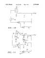
- FIG. 4is a schematic circuit diagram of a step-down switching regulator in accordance with the invention.
- FIG. 5is schematic circuit diagram of another embodiment of a step-down switching regulator in accordance with the invention.
- FIG. 6is a representation of an output voltage ripple in a circuit not making use of a hysteretic comparator
- FIG. 7is a representation of an output voltage ripple when a hysteretic comparator is used.
- FIG. 8is a schematic circuit diagram of yet another embodiment of a step-down switching regulator in accordance with the invention.
- FIG. 9is a schematic circuit diagram of yet another embodiment of a step-down switching regulator in accordance with the invention.
- FIG. 10is a schematic circuit diagram of yet another embodiment of a step-down switching regulator in accordance with the invention.
- FIG. 11is a schematic circuit diagram of yet another embodiment of a step-dow n switching regulator in accordance with the invention.
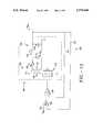
- FIG. 12is a schematic circuit diagram of a forward mode regulator in accordance with the invention.
- FIG. 1A schematic circuit diagram of a prior art step-down switching regulator is illustrated in FIG. 1. It includes a switch 10 and an LC circuit 12 comprising a n inductor 14 and a capacitor 16. A free wheeling diode 18 is connected between the ground and the switch 10. The free wheeling diode 18 provides a current path for the inductor 14 when the switch 10 opens.
- the circuitfurther includes a comparator 20 having a first input 22 connected to the circuit output via an amplifier 24 .
- the second input of the comparator, indicated by reference numeral 26receives a separately generated sawtooth input signal. It will be appreciated that as the voltage level at the circuit output 28 changes the level at the input 22 changes accordingly.
- the amplifier 24is provided with a reference voltage input 25. It should be noted that the circuit of FIG. 1 has various drawbacks. In the case of input line transients or load transients, the response time depends on the total loop speed, which is 30 dictated largely by the amplifier 24. This causes significant response time delays, causing the output to remain unregulated for relatively long periods of time.
- FIG. 2is a circuit diagram of another prior art step-down switching regulator, which uses a current mode control. It includes a switch 40 and an LC circuit 42 comprising an inductor 44 and a capacitor 46. Again, a free wheeling diode 47 is included to provide a current path for the inductor 44 when the switch 40 is turned off.
- the circuitfurther includes an inductor current sensor, which in this circuit comprises an amplifier 48 connected across a resistor 50.
- Other prior art circuitsexist that make use of different current sensing means such as a current sensing transformer.
- the circuit in FIG. 2further includes a comparator 52, receiving its inputs from the output of the amplifier 48 and from the circuit output 54, via an error amplifier 56.
- the error amplifierreceives a reference voltage, which, in this example, is indicated by reference numeral 58.
- the output of the comparatoris fed to a frequency reference, which in this circuit comprises an oscillator/flip flop circuit.
- the output of the comparator 52is fed the reset pin of an R-S flip flop 60, the set input of which is connected to an oscillator 62.
- the comparator 52receives its input from the amplifier 48.
- the oscillator 62provides a set frequency to the flip flop 60, which in turn controls the switch 40.
- the voltage across the inductor 44therefore comprises a substantially square waveform.
- the current waveform through the inductor 44will be a sawtooth waveform, the slopes of the waveform ramps depending on the voltage across the inductor 44.
- the voltage waveform across the resistor 50is a corresponding sawtooth waveform.
- Thisis fed into the amplifier 48, the output of which provides a sawtooth input for the comparator 52.
- VLdI/dt.
- FIG. 3Yet another prior art step-down switching regulator circuit is illustrated in FIG. 3.
- This circuitagain includes a switch 70 and a filtering LC circuit 72.
- the free wheeling diode 74provides a current path when the switch 70 is open.
- the amplifier 76is connected directly to the output 78, the other input 80 of the amplifier 76, receiving a reference voltage.
- the response timedepends directly on the delay in the loop. The delay is short, resulting in a quick response to both input and load fluctuations. In this circuit, the delay in the circuit itself determines the magnitude of the sawtooth ripple.
- the switch 70is turned off, allowing the output voltage to ramp down. Delays in the feedback loop cause the output voltage to oscillate about the reference voltage as indicated by the wave diagram of FIG. 6. Since the response time dictates the frequency of the oscillation, the circuit is prone to instability.
- the switching regulatorcomprises a main, input switch 84 and a low pass filter, which, in this particular circuit, comprises an LC circuit 86 that includes an inductor 88 and a capacitor 90.
- the switch 84includes an input 92, an output 94, and a control line 96.
- the switch 84can comprise any suitable controllable switch, for example a bipolar transistor or a FET device.
- a free wheeling diode 98provides a current path for the inductor 88 when the switch 84 is opened.
- the circuitincludes two feedback loops.
- the first feedback loop 100is a quick response feedback that includes a comparator 102.
- the feedback loop 100will include an appropriate driver (not shown) which can, for example, be included in the circuitry of the comparator 102.
- the second feedback loop 104is a relatively slow response feedback that includes an error amplifier 106.
- the slow response feedbackcan be used to sense the voltage at a point external to the switching circuit, and can, for instance, be used to sense the voltage at a remote location to detect power line fluctuations.
- the feedback loop 100is a fast feedback loop connected to the output line.
- the comparator 102includes built-in hysteresis, thereby providing a hysteretic window defining an upper voltage limit V 1 , indicated by reference numeral 110 in FIG. 7, and a lower voltage limit V 2 indicated by reference numeral 112.
- the voltage limits V 1 and V 2can be located on either side of a voltage V 3 that corresponds to the output of the amplifier 106.
- the voltage limits V 1 , and V 2are shown to be symmetrically located on either side of V 3 . This need not be the case.
- the voltage limits V 1 , and V 2could be asymmetrically located with respect to V 3 . Either V 1 or V 2 could, for example, coincide with V 3 . Since the delay time of the feedback loop 100 is relatively small, any switching delay due to the delay in the feedback loop 100 is insignificant in comparison with the effect of hysteresis. Furthermore, the hysteretic affect can be accurately determined in the comparator 102.
- the comparator 102seeks to keep the circuit output voltage, at the circuit output 107, at a fixed value. In the absence of resistor ladders 113, 114, the comparator 102 seeks to keep the circuit output voltage equal to the level at its positive terminal 116, the hysteresis causing a constant peak-to-peak ripple in the output voltage at the circuit output 107. In the case of input line or output load transients, the comparator 102 quickly detects output voltage changes and switches the switch 84 either on or off to compensate for the voltage fluctuation. Since the first feedback loop 100 operates independently of the error amplifier 106, no delay is caused by the response time of the error amplifier 106. Therefore, by choosing a fast comparator 102, a circuit with a well defined operating frequency and a quick response time is provided.
- the second feedback loop 104which includes the error amplifier 106, provides improved output set point accuracy, and can be used for remote sensing. It serves to compensate for voltage fluctuations at the point along the output line from which the feedback is taken.
- the loop 104is significantly slower than the loop 100, but does not interfere with the speed of the loop 100.
- the amplifier 106compares the output voltage against a reference voltage and ensures output accuracy under all load and other variations.
- the amplifier 106can be used to sense the output voltage at a remote location and compensate for power line voltage loss.
- the negative input 120 to the amplifier 106comprises a sawtooth waveform superimposed on a DC voltage. This signal is derived from the charging and discharging of the capacitor 90.
- the output capacitor 90 of the LC circuit 86is typically implemented using electrolytic or tantalum capacitors. At the switching frequency the impedance of these capacitors is dominated by their parasitic series resistance. Thus, at the switching frequency, these capacitors have the characteristics of a resistor.
- the sawtooth current of the inductorthus produces an output voltage having a sawtooth waveform proportional to the inductor current.
- a "pure" capacitorwere to be used, its charging and discharging exponential waveform could be considered as linear in the first order approximation. Any variations in the power line voltage thus shift the DC base of the signal on line 120 to cause a change in the output voltage of the amplifier 106.
- the second feedback loopprovides improved compensation for voltage fluctuations along the output line.
- the switching regulator circuitcould be used without the second feedback loop 104, making use merely of the first feedback loop 100, with its hysteretic comparator 102 receiving a DC reference voltage at its positive terminal 116.
- the absence of the second loop 104will, however, reduce the compensation accuracy for voltage fluctuations along the output line.
- FIG. 5illustrates another embodiment of a step-down switching regulator in accordance with the invention.
- the circuitis virtually identical to that illustrated in FIG. 4.
- the free wheeling diodeis replaced by a second switch 130.
- the switch 130is controlled by an output from the comparator 132, via an invertor 134.
- an invertor 134When the main, input switch 136 is on, switch 130 is off, and vice versa.
- a simple invertoris illustrated in FIG. 5, more complex circuitry could be provided to prevent simultaneous conduction of switches 130 and 136.
- the circuits of FIGS. 4 and 5can be combined by connecting a free wheeling diode in parallel to the switch 130.
- the circuitincludes a switch 140 and a low pass filter, in this case an LC filter 142 comprising an inductor 143 and a capacitor 144.
- the circuitincludes a first feedback loop 145, and a second feedback loop 146.
- the first feedback loop 145includes a comparator 147, the output of which is connected to the control line of the switch 140.
- This switch 140includes a free wheeling diode 148.
- the loop response of the feedback loop 145is relatively fast, since it directly senses the output voltage. It, thus, provides rapid compensation for both input line and load voltage fluctuations.
- the feedback loop 146once again, includes an error amplifier 149, which provides for a longer loop response time.
- the loop 146does not affect the response time of the loop 145.
- the circuitis distinguishable over the prior art circuit illustrated in FIG. 3 insofar as it includes a second voltage feedback loop for providing improved voltage compensation.
- FIG. 9This circuit is similar to the circuit of FIG. 8, but further includes a frequency reference 150.
- the circuitincludes a switch 151, and a low pass filter, in this case an LC filter 152 comprising an inductor 154 and a capacitor 156.
- the circuitfurther includes a first feedback loop 160, and a second feedback loop 162.
- the first feedback loop 160includes a comparator 164 which is fed into the frequency reference 150, which in this embodiment comprises an oscillator and flip flop circuit.
- the output of the comparator 164is fed into the reset input 166 of the R-S flip flop 168.
- the set input 170 of the flip flop 168is connected to the oscillator 172.
- the output from the flip flop 168controls the switch 151 which includes a free wheeling diode 174.
- the loop response of the feedback loop 160is relatively fast, since it directly senses the output voltage. It, thus, provides rapid compensation for both input line and load voltage fluctuations.
- the loop 162does not affect the response time of the loop 160.
- the circuitis distinguishable over that of the prior art illustrated in FIG. 2 insofar as it eliminates the current sensor of the prior art circuit. This provides for a superior voltage transient response.
- FIG. 10Another embodiment in accordance with the invention is shown in FIG. 10.
- a one shot 180is provided. This serves as a frequency reference by establishing a constant off time.
- FIG. 11This circuit is similar to the one illustrated in FIG. 8. It, however, further includes a current feedback loop 180.
- the circuit illustrated in FIG. 11includes a switch 182 having an input 184, an output 186, and a control line 188. It includes a low pass filter which, in this embodiment, takes the form of an LC filter comprising an inductor 190 and a capacitor 192.
- the comparator 194is shown as being directly connected to the control line 188 of the switch 182.
- a frequency referencecould be included in a manner similar to that illustrated and described with respect to FIGS. 9 and 10.
- the circuitincludes a first feedback loop 196, a second feedback 198, and the current feedback 180.
- the feedback 198includes an amplifier 200, the output of which is connected to a first input 202 of the comparator 194.
- the first feedback loop 196is fed into a second input 204 of the comparator 194.
- the current feedback loopis also connected to the second input 204 of the comparator 194.
- the feedback loop 196includes a capacitor 206 to block the DC offset, thereby AC coupling the first feedback loop 196 to the comparator 194.
- the current feedback loop 180includes an amplifier 210 connected across a resistor 212 thereby establishing a voltage waveform corresponding to the current through the inductor 190.
- the feedback 180further includes a capacitor 214 for eliminating the AC element of the load current.
- the output of the amplifiercorresponds to the DC output and provides a rapid response to load current fluctuations.
- step-down switching regulatorsall comprised step-down switching regulators.
- the inventionis, however, not limited to step-down regulators, but extends also to forward mode regulators, for example, buck regulators. These have the advantage of allowing voltage to be stepped up or down. They make use of a transformer to optimize the input/output ratio by virtue of the transformer winding ratio.
- the forward mode regulator of FIG. 12includes a fast feed back loop 222 and a slow feed back loop 224.
- the fast feed back loop 222extends from the output to a hysteretic comparator 226.
- the slow feed back loop 224extends from the output to an amplifier 228, the other input 230 of which receives a reference voltage.
- the comparator 226controls a switch 232. In this circuit, however, the switch is not directly connected to the output, but controls the voltage across the primary winding 234 of a transformer 236.
- the secondary winding 238 of the transformer 236is, in turn, connected to a low pass filter, which in this case, comprises an LC circuit 240.
- the LC circuit 240includes an inductor 242 and a capacitor 244.
- a diode 250provides half-wave rectification of the signal, while the diode 252 provides a current path for the inductor 242 when the switch 232 is opened.
- the power block 260is therefore slightly different to the corresponding circuitry described in the step-down switching regulators of FIGS. 4-11. The rest of the circuitry is, however, similar to that illustrated in FIG. 4. In the circuit of FIG. 12., when the switch 232 turns on, the diode 250 is forward biased and the current builds up in the inductor 242.
- the voltage across the inductormay be given by the equation:
- V Lis the inductor voltage
- V inis the voltage across the primary winding
- V outis the output voltage
- nis the transformer ratio
- the diode 250When the switch 232 turns off, the diode 250 is reverse biased and the diode 252 conducts to provide a current path for the inductor 242.
- the behavior of the circuitis therefore similar to the step-down regulator of FIG. 4, with the exception that during the time that the switch 232 is closed, the inductor voltage is dependent upon the transformer ratio. While only one switch is shown, more switches could be used for increased power.
Landscapes
- Engineering & Computer Science (AREA)
- Power Engineering (AREA)
- Physics & Mathematics (AREA)
- Electromagnetism (AREA)
- General Physics & Mathematics (AREA)
- Radar, Positioning & Navigation (AREA)
- Automation & Control Theory (AREA)
- Dc-Dc Converters (AREA)
Abstract
Description
V.sub.L =V.sub.in ×n-V.sub.out,
Claims (28)
Priority Applications (1)
| Application Number | Priority Date | Filing Date | Title |
|---|---|---|---|
| US08/512,974US5770940A (en) | 1995-08-09 | 1995-08-09 | Switching regulator |
Applications Claiming Priority (1)
| Application Number | Priority Date | Filing Date | Title |
|---|---|---|---|
| US08/512,974US5770940A (en) | 1995-08-09 | 1995-08-09 | Switching regulator |
Publications (1)
| Publication Number | Publication Date |
|---|---|
| US5770940Atrue US5770940A (en) | 1998-06-23 |
Family
ID=24041399
Family Applications (1)
| Application Number | Title | Priority Date | Filing Date |
|---|---|---|---|
| US08/512,974Expired - Fee RelatedUS5770940A (en) | 1995-08-09 | 1995-08-09 | Switching regulator |
Country Status (1)
| Country | Link |
|---|---|
| US (1) | US5770940A (en) |
Cited By (106)
| Publication number | Priority date | Publication date | Assignee | Title |
|---|---|---|---|---|
| US5877611A (en)* | 1996-10-09 | 1999-03-02 | Lucent Technologies Inc. | Simple and efficient switching regulator for fast transient loads such as microprocessors |
| US5929692A (en)* | 1997-07-11 | 1999-07-27 | Computer Products Inc. | Ripple cancellation circuit with fast load response for switch mode voltage regulators with synchronous rectification |
| US5959443A (en)* | 1997-11-14 | 1999-09-28 | Toko, Inc. | Controller circuit for controlling a step down switching regulator operating in discontinuous conduction mode |
| US6034517A (en)* | 1998-10-27 | 2000-03-07 | Linear Technology Corporation | High efficiency step-down switching regulators |
| US6127814A (en)* | 1998-11-23 | 2000-10-03 | Switch Power, Inc. | System to protect switch mode DC/DC converters against overload current |
| US6147478A (en)* | 1999-09-17 | 2000-11-14 | Texas Instruments Incorporated | Hysteretic regulator and control method having switching frequency independent from output filter |
| US6208121B1 (en)* | 1998-01-20 | 2001-03-27 | Iap Research, Inc. | Switching power supply with AC waveform capability |
| US6278265B1 (en)* | 1999-07-26 | 2001-08-21 | Nec Corporation | Switching regulator |
| US6304067B1 (en)* | 2000-12-08 | 2001-10-16 | Micrel, Incorporated | Adding a laplace transform zero to a linear integrated circuit for frequency stability |
| US6351675B1 (en) | 1999-10-04 | 2002-02-26 | Medtronic, Inc. | System and method of programming an implantable medical device |
| WO2001071894A3 (en)* | 2000-03-22 | 2002-02-28 | Univ Illinois | Oscillatorless dc-dc power converter |
| US6369555B2 (en)* | 2000-05-15 | 2002-04-09 | Texas Instruments Incorporated | Integrated low ripple, high frequency hysteretic controller for DC-DC converters |
| US6369557B1 (en)* | 2001-03-12 | 2002-04-09 | Semiconductor Components Industries Llc | Adaptive loop response in switch-mode power supply controllers |
| US6411068B1 (en) | 2000-10-03 | 2002-06-25 | Bae Systems Information & Electronic Systems Integration, Inc. | Self-oscillating switching regulator |
| US6424130B1 (en)* | 1999-04-27 | 2002-07-23 | Seiko Instruments Inc. | Output voltage detecting circuit |
| US6424132B1 (en) | 2000-12-08 | 2002-07-23 | Micrel, Incorporated | Adding a laplace transform zero to a linear integrated circuit for frequency stability |
| US6465993B1 (en) | 1999-11-01 | 2002-10-15 | John Clarkin | Voltage regulation employing a composite feedback signal |
| US6518738B1 (en) | 2000-03-29 | 2003-02-11 | Semiconductor Components Industries, Llc | Switching regulator control circuit with proactive transient response |
| US20030178975A1 (en)* | 2002-03-22 | 2003-09-25 | George Schuellein | Multi-phase buck converter |
| US6628109B2 (en)* | 2000-06-26 | 2003-09-30 | Texas Instruments Incorporated | Integrated low ripple, high frequency power efficient hysteretic controller for dc-dc converters |
| US6628106B1 (en)* | 2001-07-30 | 2003-09-30 | University Of Central Florida | Control method and circuit to provide voltage and current regulation for multiphase DC/DC converters |
| EP1186983A3 (en)* | 2000-08-31 | 2003-11-12 | STMicroelectronics S.r.l. | Switching type bandgap controller |
| US20040004470A1 (en)* | 2002-06-07 | 2004-01-08 | Hitachi, Ltd. | Switching power supply device and switching power supply system |
| US6683441B2 (en) | 2001-11-26 | 2004-01-27 | Analog Devices, Inc. | Multi-phase switching regulator |
| US6693782B1 (en) | 2000-09-20 | 2004-02-17 | Dell Products L.P. | Surge suppression for current limiting circuits |
| US6717389B1 (en)* | 2001-12-21 | 2004-04-06 | Unisys Corporation | Method and apparatus for current controlled transient reduction in a voltage regulator |
| US20040070908A1 (en)* | 2002-09-27 | 2004-04-15 | International Business Machines Corporation | Overcurrent protection of input/output devices in a data processing system |
| US6724257B2 (en) | 2002-07-31 | 2004-04-20 | Micrel, Inc. | Error amplifier circuit |
| US20040080962A1 (en)* | 2002-10-24 | 2004-04-29 | Arthur Charych | Apparatus and method for DC/DC converter having high speed and accuracy |
| US6737841B2 (en) | 2002-07-31 | 2004-05-18 | Micrel, Inc. | Amplifier circuit for adding a laplace transform zero in a linear integrated circuit |
| US20040124819A1 (en)* | 2001-05-23 | 2004-07-01 | Derek Bernardon | Direct current voltage converter with switching regulator |
| US6828766B2 (en)* | 2002-05-30 | 2004-12-07 | Stmicroelectronics S.R.L. | Voltage regulator |
| US20050156582A1 (en)* | 2004-01-21 | 2005-07-21 | Analog Devices, Inc. | Switched noise filter circuit for a dc-dc converter |
| US6937085B1 (en)* | 2003-04-25 | 2005-08-30 | T-Ram, Inc. | Sense amplifier based voltage comparator |
| US6943535B1 (en) | 2002-10-17 | 2005-09-13 | Analog Devices, Inc. | Multiple-phase DC-DC converter topology |
| US7034512B2 (en) | 2003-07-11 | 2006-04-25 | Texas Instruments Incorporated | Hysteretic controlled switch regulator with fixed off time |
| KR100588334B1 (en) | 2005-03-29 | 2006-06-09 | 삼성전자주식회사 | Dish-Dec Converter and Pulse Width Modulation Using Pseudo-Schmitt Trigger Circuits |
| US20060132113A1 (en)* | 2004-12-16 | 2006-06-22 | Cha Jae-Deok | Synchronous buck DC/DC converter to perform an improved switching operation by adjusting variable resistor |
| US20060164053A1 (en)* | 2005-01-21 | 2006-07-27 | Linear Technology Corporation | Compensation technique providing stability over broad range of output capacitor values |
| US20060209577A1 (en)* | 2003-08-27 | 2006-09-21 | Michael Hackner | Control device for controlling a charging switch in a switching regulator and method for controlling a charging switch |
| FR2884073A1 (en)* | 2006-03-23 | 2006-10-06 | Samsung Electronics Co Ltd | CONTINUOUS-CONTINUOUS CONVERTER AND METHOD OF MODULATING A PULSE WIDTH |
| US20070212596A1 (en)* | 1999-06-25 | 2007-09-13 | Nebrigic Dragan D | Single and multiple cell lithium ion battery with built-in controller |
| US20070222423A1 (en)* | 2006-03-22 | 2007-09-27 | Ming-Hsueh Chen | Switching Regulator Capable of Compensating Output Errors |
| US20070247129A1 (en)* | 2006-04-20 | 2007-10-25 | Jacobs Mark E | Optimal feedback control of switch-mode power converters |
| EP1542346A3 (en)* | 2003-12-12 | 2008-04-02 | Philips Lumileds Lighting Company LLC | DC-to-DC converter |
| US20080106242A1 (en)* | 2004-12-15 | 2008-05-08 | National Cheng Kung University | Current regulation module |
| CN100454738C (en)* | 2002-01-29 | 2009-01-21 | 英特赛尔美国股份有限公司 | Synthetic Ripple Regulator |
| US20090033289A1 (en)* | 2007-08-01 | 2009-02-05 | Intersil Americas Inc. | Voltage converter with combined buck converter and capacitive voltage divider |
| US20090033293A1 (en)* | 2007-08-01 | 2009-02-05 | Intersil Americas Inc. | Voltage converter with combined capacitive voltage divider, buck converter and battery charger |
| US7576527B1 (en)* | 2006-07-20 | 2009-08-18 | Marvell International Ltd. | Low power DC-DC converter with improved load regulation |
| US20090256538A1 (en)* | 2008-04-11 | 2009-10-15 | Inventec Corporation | Power supply module |
| US7626370B1 (en) | 2007-09-21 | 2009-12-01 | National Semiconductor Corporation | Apparatus and method for hysteretic boost DC-DC converter |
| US20100014328A1 (en)* | 2008-07-18 | 2010-01-21 | Qisda Corporation | Direct Current Generator and the Pulse generator thereof |
| US20100033153A1 (en)* | 2008-08-05 | 2010-02-11 | Intersil Americas Inc. | Pwm clock generation system and method to improve transient response of a voltage regulator |
| US20100079126A1 (en)* | 2008-09-30 | 2010-04-01 | Freescale Semiconductor, Inc. | Dual-loop dc-to-dc converter apparatus |
| US20100102785A1 (en)* | 2008-10-23 | 2010-04-29 | Young Chris M | Transient Processing Mechanism for Power Converters |
| US20100117686A1 (en)* | 2008-11-07 | 2010-05-13 | Texas Instruments Incorporated | Current mode controlled dc-to-dc converter |
| US20100123444A1 (en)* | 2008-11-20 | 2010-05-20 | Linear Technology Corporation | Accelerated response to load transients in pfm dc-to-dc converters |
| US20100181977A1 (en)* | 2007-07-27 | 2010-07-22 | Shohtaroh Sohma | Switching regulator and method for controlling operation thereof |
| US20110018512A1 (en)* | 2008-05-07 | 2011-01-27 | Kazuhiro Horii | Switching power supply device |
| US20110193539A1 (en)* | 2010-02-10 | 2011-08-11 | Texas Instruments Incorporated | Switching Regulator with Offset Correction |
| US8018212B1 (en) | 2007-08-24 | 2011-09-13 | Intersil Americas Inc. | Buck-boost regulator |
| US20110316500A1 (en)* | 2010-06-23 | 2011-12-29 | Volterra Semiconductor Corporation | Controlled delivery of a charging current to a boost capacitor of a voltage regulator |
| US20120153910A1 (en)* | 2010-12-16 | 2012-06-21 | International Business Machines Corporation | Dual-loop voltage regulator architecture with high dc accuracy and fast response time |
| US20120223667A1 (en)* | 2011-03-04 | 2012-09-06 | Denso Corporation | Power conversion apparatus |
| CN102801306A (en)* | 2012-08-14 | 2012-11-28 | 成都芯源系统有限公司 | Control circuit and control method of high-side buck conversion circuit |
| US20130015829A1 (en)* | 2011-07-14 | 2013-01-17 | Paolo Menegoli | Synchronization of hysteretic power converters |
| TWI386771B (en)* | 2009-05-13 | 2013-02-21 | Vanguard Int Semiconduct Corp | Voltage regulator and ac-dc converter |
| US20130329470A1 (en)* | 2010-12-22 | 2013-12-12 | Stmicroelectronics S.R.I. | Control device for a dc-dc converter |
| WO2014093090A1 (en)* | 2012-12-11 | 2014-06-19 | Analog Devices, Inc. | Target voltage generator for dc to dc converter |
| US20140176099A1 (en)* | 2012-12-21 | 2014-06-26 | Samsung Electro-Mechanics Co., Ltd. | Voltage supply device |
| US8786270B2 (en) | 2010-11-08 | 2014-07-22 | Intersil Americas Inc. | Synthetic ripple regulator with frequency control |
| CN103956896A (en)* | 2013-03-29 | 2014-07-30 | 成都芯源系统有限公司 | Voltage conversion circuit and control method |
| US20140225445A1 (en)* | 2011-09-13 | 2014-08-14 | Toshiba Mitsubishi-Electric Industrial Systems Corporation | Peak cut system |
| CN104009628A (en)* | 2013-02-22 | 2014-08-27 | 杰力科技股份有限公司 | voltage converter |
| US9086708B2 (en) | 2012-12-31 | 2015-07-21 | Gazelle Semiconductor Inc. | High slew rate switching regulator circuits and methods |
| US20150253790A1 (en)* | 2014-03-05 | 2015-09-10 | Dialog Semiconductor Gmbh | Apparatus, System and Method for Voltage Regulator with an Improved Voltage Regulation Using a Remote Feedback Loop and Filter |
| US20150326008A1 (en)* | 2014-05-09 | 2015-11-12 | Power Integrations, Inc. | Fault protection circuit |
| US20150381037A1 (en)* | 2014-06-25 | 2015-12-31 | Semiconductor Components Industries, Llc | Power converter using hysteretic boost architecture and method therefor |
| US20160085284A1 (en)* | 2014-09-24 | 2016-03-24 | Rohm Co., Ltd. | Power supply device |
| US20160085251A1 (en)* | 2014-09-24 | 2016-03-24 | Rohm Co., Ltd. | Power supply device |
| US20160094134A1 (en)* | 2014-09-25 | 2016-03-31 | Denso Corporation | Power conversion apparatus |
| WO2016114911A1 (en)* | 2015-01-12 | 2016-07-21 | Hua Cao | Switching regulator and control method thereof |
| US9444340B2 (en) | 2014-06-26 | 2016-09-13 | Gazelle Semiconductor, Inc. | Circuits and methods for providing current to a load |
| US9577532B2 (en) | 2013-07-25 | 2017-02-21 | Gazelle Semiconductor, Inc. | Switching regulator circuits and methods |
| US9735574B2 (en) | 2012-12-31 | 2017-08-15 | Gazelle Semiconductor, Inc. | Switching regulator circuits and methods |
| US9760520B2 (en) | 2014-07-11 | 2017-09-12 | Covidien Lp | Dynamic system management bus for an electrosurgical system |
| US9866104B2 (en) | 2013-11-26 | 2018-01-09 | Gazelle Semiconductor, Inc. | Circuits and methods for operating a switching regulator |
| US9866115B2 (en) | 2016-04-01 | 2018-01-09 | Nxp B.V. | Reduction of frequency variation for ripple based, constant-on-time DC-DC converters |
| US9887626B2 (en) | 2016-01-11 | 2018-02-06 | Semiconductor Components Industries, Llc | Adaptive feedback control system and method for voltage regulators |
| US9899916B2 (en) | 2012-11-13 | 2018-02-20 | Toyota Jidosha Kabushiki Kaisha | Boost converter control apparatus |
| US9941792B2 (en) | 2016-04-01 | 2018-04-10 | Nxp B.V. | DC offset correction for inductor current ripple based, constant-on-time DC-DC converters |
| US10084379B2 (en) | 2012-11-13 | 2018-09-25 | Toyota Jidosha Kabushiki Kaisha | Boost converter control apparatus |
| US20190097538A1 (en)* | 2015-08-25 | 2019-03-28 | Huawei Technologies Co., Ltd. | Voltage Conversion Circuit and Method, and Multiphase Parallel Power System |
| US10298247B1 (en)* | 2018-03-13 | 2019-05-21 | Cirrus Logic, Inc. | Modulators |
| US20190238056A1 (en)* | 2016-10-26 | 2019-08-01 | Silanna Asia Pte Ltd | Power converter with predictive pulse width modulator control |
| US10644660B2 (en)* | 2017-07-24 | 2020-05-05 | Cirrus Logic, Inc. | Transducer driver circuitry |
| WO2020166307A1 (en)* | 2019-02-15 | 2020-08-20 | 株式会社オートネットワーク技術研究所 | Vehicle-mounted power supply device |
| US11218076B2 (en)* | 2018-10-17 | 2022-01-04 | Texas Instruments Incorporated | Ultra-low Iq buck converter with switchable error amplifier |
| CN114253333A (en)* | 2021-12-16 | 2022-03-29 | 乐鑫信息科技(上海)股份有限公司 | Voltage stabilizer |
| US11323147B1 (en)* | 2021-06-07 | 2022-05-03 | Futurecom Systems Group, ULC | Reducing insertion loss in a switch for a communication device |
| US11402860B2 (en)* | 2020-02-18 | 2022-08-02 | Silicon Laboratories Inc. | Voltage regulator having minimal fluctuation in multiple operating modes |
| US20220404410A1 (en)* | 2021-06-18 | 2022-12-22 | Samsung Electronics Co., Ltd. | Duty timing detector for detecting duty timing of toggle signal, device including the duty timing detector, and method of operating toggle signal receiving device |
| US11543843B2 (en) | 2020-02-18 | 2023-01-03 | Silicon Laboratories Inc. | Providing low power charge pump for integrated circuit |
| US12041533B2 (en) | 2022-05-10 | 2024-07-16 | Motorola Solutions, Inc. | System and method for configuring a portable communication system |
| US12095496B2 (en) | 2021-10-18 | 2024-09-17 | Futurecom Systems Group, ULC | Self-diagnostic systems and method for a transceiver |
Citations (3)
| Publication number | Priority date | Publication date | Assignee | Title |
|---|---|---|---|---|
| US5399958A (en)* | 1993-05-31 | 1995-03-21 | Nec Corporation | Switching power supply circuit having a reduced ripple voltage |
| US5481178A (en)* | 1993-03-23 | 1996-01-02 | Linear Technology Corporation | Control circuit and method for maintaining high efficiency over broad current ranges in a switching regulator circuit |
| US5523936A (en)* | 1994-07-25 | 1996-06-04 | Chun-Shan Institute Of Science And Technology | Built-in input filter forward converter |
- 1995
- 1995-08-09USUS08/512,974patent/US5770940A/ennot_activeExpired - Fee Related
Patent Citations (3)
| Publication number | Priority date | Publication date | Assignee | Title |
|---|---|---|---|---|
| US5481178A (en)* | 1993-03-23 | 1996-01-02 | Linear Technology Corporation | Control circuit and method for maintaining high efficiency over broad current ranges in a switching regulator circuit |
| US5399958A (en)* | 1993-05-31 | 1995-03-21 | Nec Corporation | Switching power supply circuit having a reduced ripple voltage |
| US5523936A (en)* | 1994-07-25 | 1996-06-04 | Chun-Shan Institute Of Science And Technology | Built-in input filter forward converter |
Cited By (177)
| Publication number | Priority date | Publication date | Assignee | Title |
|---|---|---|---|---|
| USRE37738E1 (en)* | 1996-10-09 | 2002-06-11 | Milivoje Slobodan Brkovic | Simple and efficient switching regulator for fast transient loads such as microprocessors |
| US5877611A (en)* | 1996-10-09 | 1999-03-02 | Lucent Technologies Inc. | Simple and efficient switching regulator for fast transient loads such as microprocessors |
| US5929692A (en)* | 1997-07-11 | 1999-07-27 | Computer Products Inc. | Ripple cancellation circuit with fast load response for switch mode voltage regulators with synchronous rectification |
| US5959443A (en)* | 1997-11-14 | 1999-09-28 | Toko, Inc. | Controller circuit for controlling a step down switching regulator operating in discontinuous conduction mode |
| US6208121B1 (en)* | 1998-01-20 | 2001-03-27 | Iap Research, Inc. | Switching power supply with AC waveform capability |
| US6465995B2 (en) | 1998-01-20 | 2002-10-15 | Iap Research, Inc. | Switching power supply with AC waveform capability |
| US6034517A (en)* | 1998-10-27 | 2000-03-07 | Linear Technology Corporation | High efficiency step-down switching regulators |
| US6127814A (en)* | 1998-11-23 | 2000-10-03 | Switch Power, Inc. | System to protect switch mode DC/DC converters against overload current |
| US6424130B1 (en)* | 1999-04-27 | 2002-07-23 | Seiko Instruments Inc. | Output voltage detecting circuit |
| US9397370B2 (en) | 1999-06-25 | 2016-07-19 | The Board Of Trustees Of The University Of Illinois | Single and multiple cell battery with built-in controller |
| US20070212596A1 (en)* | 1999-06-25 | 2007-09-13 | Nebrigic Dragan D | Single and multiple cell lithium ion battery with built-in controller |
| US6278265B1 (en)* | 1999-07-26 | 2001-08-21 | Nec Corporation | Switching regulator |
| KR100451890B1 (en)* | 1999-07-26 | 2004-10-08 | 엔이씨 일렉트로닉스 가부시키가이샤 | Switching regulator |
| US6147478A (en)* | 1999-09-17 | 2000-11-14 | Texas Instruments Incorporated | Hysteretic regulator and control method having switching frequency independent from output filter |
| US6351675B1 (en) | 1999-10-04 | 2002-02-26 | Medtronic, Inc. | System and method of programming an implantable medical device |
| US6465993B1 (en) | 1999-11-01 | 2002-10-15 | John Clarkin | Voltage regulation employing a composite feedback signal |
| US20040056642A1 (en)* | 2000-03-22 | 2004-03-25 | Nebrigic Dragan Danilo | Oscillatorless dc-dc power converter |
| WO2001071894A3 (en)* | 2000-03-22 | 2002-02-28 | Univ Illinois | Oscillatorless dc-dc power converter |
| US7208928B2 (en) | 2000-03-22 | 2007-04-24 | The Board Of Trustrees Of The University Of Illinois | Oscillatorless DC-DC power converter |
| US6518738B1 (en) | 2000-03-29 | 2003-02-11 | Semiconductor Components Industries, Llc | Switching regulator control circuit with proactive transient response |
| US6369555B2 (en)* | 2000-05-15 | 2002-04-09 | Texas Instruments Incorporated | Integrated low ripple, high frequency hysteretic controller for DC-DC converters |
| US6628109B2 (en)* | 2000-06-26 | 2003-09-30 | Texas Instruments Incorporated | Integrated low ripple, high frequency power efficient hysteretic controller for dc-dc converters |
| EP1186983A3 (en)* | 2000-08-31 | 2003-11-12 | STMicroelectronics S.r.l. | Switching type bandgap controller |
| US6693782B1 (en) | 2000-09-20 | 2004-02-17 | Dell Products L.P. | Surge suppression for current limiting circuits |
| US6411068B1 (en) | 2000-10-03 | 2002-06-25 | Bae Systems Information & Electronic Systems Integration, Inc. | Self-oscillating switching regulator |
| US6304067B1 (en)* | 2000-12-08 | 2001-10-16 | Micrel, Incorporated | Adding a laplace transform zero to a linear integrated circuit for frequency stability |
| US6424132B1 (en) | 2000-12-08 | 2002-07-23 | Micrel, Incorporated | Adding a laplace transform zero to a linear integrated circuit for frequency stability |
| US6369557B1 (en)* | 2001-03-12 | 2002-04-09 | Semiconductor Components Industries Llc | Adaptive loop response in switch-mode power supply controllers |
| US6864671B2 (en)* | 2001-05-23 | 2005-03-08 | Infineon Technologies Ag | Direct current voltage converter with switching regulator |
| US20040124819A1 (en)* | 2001-05-23 | 2004-07-01 | Derek Bernardon | Direct current voltage converter with switching regulator |
| US6628106B1 (en)* | 2001-07-30 | 2003-09-30 | University Of Central Florida | Control method and circuit to provide voltage and current regulation for multiphase DC/DC converters |
| USRE39976E1 (en)* | 2001-11-26 | 2008-01-01 | Analog Devices, Inc. | Multi-phase switching regulator |
| US6683441B2 (en) | 2001-11-26 | 2004-01-27 | Analog Devices, Inc. | Multi-phase switching regulator |
| US6717389B1 (en)* | 2001-12-21 | 2004-04-06 | Unisys Corporation | Method and apparatus for current controlled transient reduction in a voltage regulator |
| CN100454738C (en)* | 2002-01-29 | 2009-01-21 | 英特赛尔美国股份有限公司 | Synthetic Ripple Regulator |
| US20030178975A1 (en)* | 2002-03-22 | 2003-09-25 | George Schuellein | Multi-phase buck converter |
| US6806689B2 (en) | 2002-03-22 | 2004-10-19 | International Rectifier Corporation | Multi-phase buck converter |
| US6828766B2 (en)* | 2002-05-30 | 2004-12-07 | Stmicroelectronics S.R.L. | Voltage regulator |
| US20060091870A1 (en)* | 2002-06-07 | 2006-05-04 | Renesas Technology Corp. | Switching power supply device and switching power supply system |
| US7109693B2 (en) | 2002-06-07 | 2006-09-19 | Renesas Technology Corp. | Switching power supply device and switching power supply system |
| US20040004470A1 (en)* | 2002-06-07 | 2004-01-08 | Hitachi, Ltd. | Switching power supply device and switching power supply system |
| US6979985B2 (en)* | 2002-06-07 | 2005-12-27 | Renesas Technology Corp. | Switching power supply device and switching power supply system |
| US20060158168A1 (en)* | 2002-06-07 | 2006-07-20 | Shinichi Yoshida | Switching power supply device and switching power supply system |
| US7091711B2 (en) | 2002-06-07 | 2006-08-15 | Renesas Technology Corp. | Switching power supply device and switching power supply system |
| US6737841B2 (en) | 2002-07-31 | 2004-05-18 | Micrel, Inc. | Amplifier circuit for adding a laplace transform zero in a linear integrated circuit |
| US6724257B2 (en) | 2002-07-31 | 2004-04-20 | Micrel, Inc. | Error amplifier circuit |
| US20040070908A1 (en)* | 2002-09-27 | 2004-04-15 | International Business Machines Corporation | Overcurrent protection of input/output devices in a data processing system |
| US6943535B1 (en) | 2002-10-17 | 2005-09-13 | Analog Devices, Inc. | Multiple-phase DC-DC converter topology |
| US6760238B2 (en)* | 2002-10-24 | 2004-07-06 | Bc Systems, Inc | Apparatus and method for DC/DC converter having high speed and accuracy |
| US20040080962A1 (en)* | 2002-10-24 | 2004-04-29 | Arthur Charych | Apparatus and method for DC/DC converter having high speed and accuracy |
| US6937085B1 (en)* | 2003-04-25 | 2005-08-30 | T-Ram, Inc. | Sense amplifier based voltage comparator |
| US7034512B2 (en) | 2003-07-11 | 2006-04-25 | Texas Instruments Incorporated | Hysteretic controlled switch regulator with fixed off time |
| US20060209577A1 (en)* | 2003-08-27 | 2006-09-21 | Michael Hackner | Control device for controlling a charging switch in a switching regulator and method for controlling a charging switch |
| US7138790B2 (en) | 2003-08-27 | 2006-11-21 | Fraunhofer-Gesellschaft Zur Foerderung Der Angewandten Forschung E.V. | Control device for controlling a charging switch in a switching regulator and method for controlling a charging switch |
| EP1542346A3 (en)* | 2003-12-12 | 2008-04-02 | Philips Lumileds Lighting Company LLC | DC-to-DC converter |
| CN1910807B (en)* | 2004-01-21 | 2011-05-11 | 半导体元件工业有限公司 | Switched noise filter circuit for a dc-dc converter |
| US20050156582A1 (en)* | 2004-01-21 | 2005-07-21 | Analog Devices, Inc. | Switched noise filter circuit for a dc-dc converter |
| US6958594B2 (en) | 2004-01-21 | 2005-10-25 | Analog Devices, Inc. | Switched noise filter circuit for a DC-DC converter |
| US7808221B2 (en)* | 2004-12-15 | 2010-10-05 | National Cheng Kung University | Current regulation module |
| US20080106242A1 (en)* | 2004-12-15 | 2008-05-08 | National Cheng Kung University | Current regulation module |
| US20060132113A1 (en)* | 2004-12-16 | 2006-06-22 | Cha Jae-Deok | Synchronous buck DC/DC converter to perform an improved switching operation by adjusting variable resistor |
| USRE44180E1 (en)* | 2004-12-16 | 2013-04-30 | Samsung Electronics Co., Ltd. | Synchronous buck DC/DC converter to perform an improved switching operation by adjusting variable resistor |
| US7365526B2 (en)* | 2004-12-16 | 2008-04-29 | Samsung Electronics Co., Ltd. | Synchronous buck DC/DC converter to perform an improved switching operation by adjusting variable resistor |
| US7218082B2 (en)* | 2005-01-21 | 2007-05-15 | Linear Technology Corporation | Compensation technique providing stability over broad range of output capacitor values |
| US20060164053A1 (en)* | 2005-01-21 | 2006-07-27 | Linear Technology Corporation | Compensation technique providing stability over broad range of output capacitor values |
| US20060220627A1 (en)* | 2005-03-29 | 2006-10-05 | Samsung Electronics Co., Ltd. | DC-DC converter utilizing a modified Schmitt trigger circuit and method of modulating a pulse width |
| US7417412B2 (en) | 2005-03-29 | 2008-08-26 | Samsung Electronics Co., Ltd. | DC-DC converter utilizing a modified Schmitt trigger circuit and method of modulating a pulse width |
| KR100588334B1 (en) | 2005-03-29 | 2006-06-09 | 삼성전자주식회사 | Dish-Dec Converter and Pulse Width Modulation Using Pseudo-Schmitt Trigger Circuits |
| US7508181B2 (en)* | 2006-03-22 | 2009-03-24 | Anpec Electronics Corporation | Switching regulator capable of compensating output errors |
| US20070222423A1 (en)* | 2006-03-22 | 2007-09-27 | Ming-Hsueh Chen | Switching Regulator Capable of Compensating Output Errors |
| FR2884073A1 (en)* | 2006-03-23 | 2006-10-06 | Samsung Electronics Co Ltd | CONTINUOUS-CONTINUOUS CONVERTER AND METHOD OF MODULATING A PULSE WIDTH |
| US20070247129A1 (en)* | 2006-04-20 | 2007-10-25 | Jacobs Mark E | Optimal feedback control of switch-mode power converters |
| US7459893B2 (en) | 2006-04-20 | 2008-12-02 | Mark E Jacobs | Optimal feedback control of switch-mode power converters |
| US7576527B1 (en)* | 2006-07-20 | 2009-08-18 | Marvell International Ltd. | Low power DC-DC converter with improved load regulation |
| US7990126B1 (en) | 2006-07-20 | 2011-08-02 | Marvell International, Ltd. | Low power DC-DC converter with improved load regulation |
| US8207721B2 (en)* | 2007-07-27 | 2012-06-26 | Ricoh Company, Ltd. | Switching regulator capable of stable operation and improved frequency characteristics in a broad input and output voltage range and method for controlling operation thereof |
| US20100181977A1 (en)* | 2007-07-27 | 2010-07-22 | Shohtaroh Sohma | Switching regulator and method for controlling operation thereof |
| US8427113B2 (en) | 2007-08-01 | 2013-04-23 | Intersil Americas LLC | Voltage converter with combined buck converter and capacitive voltage divider |
| US20090033289A1 (en)* | 2007-08-01 | 2009-02-05 | Intersil Americas Inc. | Voltage converter with combined buck converter and capacitive voltage divider |
| US20090033293A1 (en)* | 2007-08-01 | 2009-02-05 | Intersil Americas Inc. | Voltage converter with combined capacitive voltage divider, buck converter and battery charger |
| US8018212B1 (en) | 2007-08-24 | 2011-09-13 | Intersil Americas Inc. | Buck-boost regulator |
| US8085011B1 (en) | 2007-08-24 | 2011-12-27 | Intersil Americas Inc. | Boost regulator using synthetic ripple regulation |
| US7626370B1 (en) | 2007-09-21 | 2009-12-01 | National Semiconductor Corporation | Apparatus and method for hysteretic boost DC-DC converter |
| US8076916B2 (en)* | 2008-04-11 | 2011-12-13 | Inventec Corporation | Power supply module |
| US20090256538A1 (en)* | 2008-04-11 | 2009-10-15 | Inventec Corporation | Power supply module |
| US20110018512A1 (en)* | 2008-05-07 | 2011-01-27 | Kazuhiro Horii | Switching power supply device |
| US8278896B2 (en)* | 2008-05-07 | 2012-10-02 | Cosel Co., Ltd. | Switching power supply device |
| US20100014328A1 (en)* | 2008-07-18 | 2010-01-21 | Qisda Corporation | Direct Current Generator and the Pulse generator thereof |
| US8179112B2 (en)* | 2008-07-18 | 2012-05-15 | Qisda Corporation | Direct current generator and the pulse generator thereof |
| US8148967B2 (en) | 2008-08-05 | 2012-04-03 | Intersil Americas Inc. | PWM clock generation system and method to improve transient response of a voltage regulator |
| US20100033153A1 (en)* | 2008-08-05 | 2010-02-11 | Intersil Americas Inc. | Pwm clock generation system and method to improve transient response of a voltage regulator |
| US20100079126A1 (en)* | 2008-09-30 | 2010-04-01 | Freescale Semiconductor, Inc. | Dual-loop dc-to-dc converter apparatus |
| US7880457B2 (en)* | 2008-09-30 | 2011-02-01 | Freescale Semiconductor, Inc. | Dual-loop DC-to-DC converter apparatus |
| TWI422128B (en)* | 2008-10-23 | 2014-01-01 | Intersil Inc | Power regulator,and system and method for controlling output of power regulator |
| US8638076B2 (en)* | 2008-10-23 | 2014-01-28 | Intersil Americas Inc. | Transient processing mechanism for power converters |
| US20100102785A1 (en)* | 2008-10-23 | 2010-04-29 | Young Chris M | Transient Processing Mechanism for Power Converters |
| US7893675B2 (en)* | 2008-11-07 | 2011-02-22 | Texas Instruments Incorporated | Current mode controlled DC-to-DC converter |
| US20100117686A1 (en)* | 2008-11-07 | 2010-05-13 | Texas Instruments Incorporated | Current mode controlled dc-to-dc converter |
| US8030907B2 (en)* | 2008-11-20 | 2011-10-04 | Linear Technology Corporation | Accelerated response to load transients in PFM DC-to-DC converters |
| US20100123444A1 (en)* | 2008-11-20 | 2010-05-20 | Linear Technology Corporation | Accelerated response to load transients in pfm dc-to-dc converters |
| TWI452814B (en)* | 2008-11-20 | 2014-09-11 | Linear Techn Inc | Pulse controller circuit and dc-to-dc converter having the same |
| TWI386771B (en)* | 2009-05-13 | 2013-02-21 | Vanguard Int Semiconduct Corp | Voltage regulator and ac-dc converter |
| US20110193539A1 (en)* | 2010-02-10 | 2011-08-11 | Texas Instruments Incorporated | Switching Regulator with Offset Correction |
| US20110316500A1 (en)* | 2010-06-23 | 2011-12-29 | Volterra Semiconductor Corporation | Controlled delivery of a charging current to a boost capacitor of a voltage regulator |
| US9397571B2 (en)* | 2010-06-23 | 2016-07-19 | Volterra Semiconductor Corporation | Controlled delivery of a charging current to a boost capacitor of a voltage regulator |
| US8786270B2 (en) | 2010-11-08 | 2014-07-22 | Intersil Americas Inc. | Synthetic ripple regulator with frequency control |
| US8841893B2 (en)* | 2010-12-16 | 2014-09-23 | International Business Machines Corporation | Dual-loop voltage regulator architecture with high DC accuracy and fast response time |
| US20120153910A1 (en)* | 2010-12-16 | 2012-06-21 | International Business Machines Corporation | Dual-loop voltage regulator architecture with high dc accuracy and fast response time |
| US9397574B2 (en)* | 2010-12-22 | 2016-07-19 | Stmicroelectronics S.R.L. | Control device for a DC-DC converter |
| US20130329470A1 (en)* | 2010-12-22 | 2013-12-12 | Stmicroelectronics S.R.I. | Control device for a dc-dc converter |
| US8587279B2 (en)* | 2011-03-04 | 2013-11-19 | Denso Corporation | Power conversion apparatus |
| US20120223667A1 (en)* | 2011-03-04 | 2012-09-06 | Denso Corporation | Power conversion apparatus |
| US8907644B2 (en)* | 2011-07-14 | 2014-12-09 | Eta Semiconductor Inc. | Synchronization of hysteretic power converters |
| US20130015829A1 (en)* | 2011-07-14 | 2013-01-17 | Paolo Menegoli | Synchronization of hysteretic power converters |
| US20140225445A1 (en)* | 2011-09-13 | 2014-08-14 | Toshiba Mitsubishi-Electric Industrial Systems Corporation | Peak cut system |
| CN102801306A (en)* | 2012-08-14 | 2012-11-28 | 成都芯源系统有限公司 | Control circuit and control method of high-side buck conversion circuit |
| CN102801306B (en)* | 2012-08-14 | 2014-12-24 | 成都芯源系统有限公司 | Control circuit and control method of high-side buck conversion circuit |
| US10084379B2 (en) | 2012-11-13 | 2018-09-25 | Toyota Jidosha Kabushiki Kaisha | Boost converter control apparatus |
| US9899916B2 (en) | 2012-11-13 | 2018-02-20 | Toyota Jidosha Kabushiki Kaisha | Boost converter control apparatus |
| US9099924B2 (en) | 2012-12-11 | 2015-08-04 | Analog Devices, Inc. | Target voltage generator for a DC to DC converter, a combination of a target voltage generator and a DC to DC converter, and a method of operating a DC to DC converter |
| WO2014093090A1 (en)* | 2012-12-11 | 2014-06-19 | Analog Devices, Inc. | Target voltage generator for dc to dc converter |
| US20140176099A1 (en)* | 2012-12-21 | 2014-06-26 | Samsung Electro-Mechanics Co., Ltd. | Voltage supply device |
| US9086708B2 (en) | 2012-12-31 | 2015-07-21 | Gazelle Semiconductor Inc. | High slew rate switching regulator circuits and methods |
| US9735574B2 (en) | 2012-12-31 | 2017-08-15 | Gazelle Semiconductor, Inc. | Switching regulator circuits and methods |
| CN104009628B (en)* | 2013-02-22 | 2016-12-28 | 杰力科技股份有限公司 | Voltage converter |
| CN104009628A (en)* | 2013-02-22 | 2014-08-27 | 杰力科技股份有限公司 | voltage converter |
| CN103956896A (en)* | 2013-03-29 | 2014-07-30 | 成都芯源系统有限公司 | Voltage conversion circuit and control method |
| CN103956896B (en)* | 2013-03-29 | 2016-08-17 | 成都芯源系统有限公司 | Voltage conversion circuit and control method |
| US9577532B2 (en) | 2013-07-25 | 2017-02-21 | Gazelle Semiconductor, Inc. | Switching regulator circuits and methods |
| US9866104B2 (en) | 2013-11-26 | 2018-01-09 | Gazelle Semiconductor, Inc. | Circuits and methods for operating a switching regulator |
| US9471071B2 (en)* | 2014-03-05 | 2016-10-18 | Dialog Semiconductor (Uk) Limited | Apparatus, system and method for voltage regulator with an improved voltage regulation using a remote feedback loop and filter |
| US20150253790A1 (en)* | 2014-03-05 | 2015-09-10 | Dialog Semiconductor Gmbh | Apparatus, System and Method for Voltage Regulator with an Improved Voltage Regulation Using a Remote Feedback Loop and Filter |
| US20150326008A1 (en)* | 2014-05-09 | 2015-11-12 | Power Integrations, Inc. | Fault protection circuit |
| US11005365B2 (en)* | 2014-06-25 | 2021-05-11 | Semiconductor Components Industries, Llc | Power converter using hysteretic boost architecture and method therefor |
| CN105322792A (en)* | 2014-06-25 | 2016-02-10 | 半导体元件工业有限责任公司 | Power converter using hysteretic boost architecture and method therefor |
| US20150381037A1 (en)* | 2014-06-25 | 2015-12-31 | Semiconductor Components Industries, Llc | Power converter using hysteretic boost architecture and method therefor |
| US9444340B2 (en) | 2014-06-26 | 2016-09-13 | Gazelle Semiconductor, Inc. | Circuits and methods for providing current to a load |
| US9760520B2 (en) | 2014-07-11 | 2017-09-12 | Covidien Lp | Dynamic system management bus for an electrosurgical system |
| US10891249B2 (en) | 2014-07-11 | 2021-01-12 | Covidien Lp | Dynamic system management bus |
| US10459867B2 (en) | 2014-07-11 | 2019-10-29 | Covidien Lp | Method for dynamic bus communication for an electrosurgical generator |
| US9563241B2 (en)* | 2014-09-24 | 2017-02-07 | Rohm Co., Ltd. | Power supply device including an electro-conductive cable wound around an inductor or output capacitor |
| US9563214B2 (en)* | 2014-09-24 | 2017-02-07 | Rohm Co., Ltd. | Power supply device including an electro-conductive cable wound around an output capacitor |
| US20160085284A1 (en)* | 2014-09-24 | 2016-03-24 | Rohm Co., Ltd. | Power supply device |
| US20160085251A1 (en)* | 2014-09-24 | 2016-03-24 | Rohm Co., Ltd. | Power supply device |
| US20160094134A1 (en)* | 2014-09-25 | 2016-03-31 | Denso Corporation | Power conversion apparatus |
| US9692307B2 (en)* | 2014-09-25 | 2017-06-27 | Denso Corporation | Power conversion apparatus |
| CN107112895B (en)* | 2015-01-12 | 2020-04-17 | 曹华 | Switching regulator and control method thereof |
| JP2018523446A (en)* | 2015-01-12 | 2018-08-16 | ツァォ ホア | Switching regulator and control method thereof |
| WO2016114911A1 (en)* | 2015-01-12 | 2016-07-21 | Hua Cao | Switching regulator and control method thereof |
| CN107112895A (en)* | 2015-01-12 | 2017-08-29 | 曹华 | Switching regulator and its control method |
| US20190097538A1 (en)* | 2015-08-25 | 2019-03-28 | Huawei Technologies Co., Ltd. | Voltage Conversion Circuit and Method, and Multiphase Parallel Power System |
| US10432091B2 (en) | 2016-01-11 | 2019-10-01 | Semiconductor Components Industries, Llc | Adaptive feedback control system and method for voltage regulators |
| US9887626B2 (en) | 2016-01-11 | 2018-02-06 | Semiconductor Components Industries, Llc | Adaptive feedback control system and method for voltage regulators |
| US9866115B2 (en) | 2016-04-01 | 2018-01-09 | Nxp B.V. | Reduction of frequency variation for ripple based, constant-on-time DC-DC converters |
| US9941792B2 (en) | 2016-04-01 | 2018-04-10 | Nxp B.V. | DC offset correction for inductor current ripple based, constant-on-time DC-DC converters |
| US20190238056A1 (en)* | 2016-10-26 | 2019-08-01 | Silanna Asia Pte Ltd | Power converter with predictive pulse width modulator control |
| US10707758B2 (en)* | 2016-10-26 | 2020-07-07 | Silanna Asia Pte Ltd | Power converter with predictive pulse width modulator control |
| US10644660B2 (en)* | 2017-07-24 | 2020-05-05 | Cirrus Logic, Inc. | Transducer driver circuitry |
| US11539335B2 (en) | 2017-07-24 | 2022-12-27 | Cirrus Logic, Inc. | Transducer driver circuitry |
| US10298247B1 (en)* | 2018-03-13 | 2019-05-21 | Cirrus Logic, Inc. | Modulators |
| GB2585587B (en)* | 2018-03-13 | 2022-05-18 | Cirrus Logic Int Semiconductor Ltd | Modulators |
| US11218076B2 (en)* | 2018-10-17 | 2022-01-04 | Texas Instruments Incorporated | Ultra-low Iq buck converter with switchable error amplifier |
| US11764674B2 (en) | 2019-02-15 | 2023-09-19 | Autonetworks Technologies, Ltd. | On-board power supply device |
| CN113366749A (en)* | 2019-02-15 | 2021-09-07 | 株式会社自动网络技术研究所 | Vehicle-mounted power supply device |
| JP7028205B2 (en) | 2019-02-15 | 2022-03-02 | 株式会社オートネットワーク技術研究所 | In-vehicle power supply |
| JP2020137190A (en)* | 2019-02-15 | 2020-08-31 | 株式会社オートネットワーク技術研究所 | In-vehicle power supply |
| WO2020166307A1 (en)* | 2019-02-15 | 2020-08-20 | 株式会社オートネットワーク技術研究所 | Vehicle-mounted power supply device |
| US12189408B2 (en) | 2020-02-18 | 2025-01-07 | Silicon Laboratories Inc. | Voltage regulator having minimal fluctuation in multiple operating modes |
| US11402860B2 (en)* | 2020-02-18 | 2022-08-02 | Silicon Laboratories Inc. | Voltage regulator having minimal fluctuation in multiple operating modes |
| US11543843B2 (en) | 2020-02-18 | 2023-01-03 | Silicon Laboratories Inc. | Providing low power charge pump for integrated circuit |
| US11323147B1 (en)* | 2021-06-07 | 2022-05-03 | Futurecom Systems Group, ULC | Reducing insertion loss in a switch for a communication device |
| US20220404410A1 (en)* | 2021-06-18 | 2022-12-22 | Samsung Electronics Co., Ltd. | Duty timing detector for detecting duty timing of toggle signal, device including the duty timing detector, and method of operating toggle signal receiving device |
| US11598797B2 (en)* | 2021-06-18 | 2023-03-07 | Samsung Electronics Co., Ltd. | Duty timing detector for detecting duty timing of toggle signal, device including the duty timing detector, and method of operating toggle signal receiving device |
| US12095496B2 (en) | 2021-10-18 | 2024-09-17 | Futurecom Systems Group, ULC | Self-diagnostic systems and method for a transceiver |
| CN114253333B (en)* | 2021-12-16 | 2023-09-29 | 乐鑫信息科技(上海)股份有限公司 | Voltage stabilizing device |
| CN114253333A (en)* | 2021-12-16 | 2022-03-29 | 乐鑫信息科技(上海)股份有限公司 | Voltage stabilizer |
| US12041533B2 (en) | 2022-05-10 | 2024-07-16 | Motorola Solutions, Inc. | System and method for configuring a portable communication system |
Similar Documents
| Publication | Publication Date | Title |
|---|---|---|
| US5770940A (en) | Switching regulator | |
| US5264782A (en) | Dropout recovery circuit | |
| US5367247A (en) | Critically continuous boost converter | |
| US5264780A (en) | On time control and gain circuit | |
| US5929620A (en) | Switching regulators having a synchronizable oscillator frequency with constant ramp amplitude | |
| US6222356B1 (en) | Current mode switching regulator configured such that a measuring resistor is not needed to measure the current at an inductor | |
| EP1969705B1 (en) | Switching regulator slope compensation generator circuit | |
| US6275397B1 (en) | Power factor correction control circuit for regulating the current waveshape in a switching power supply | |
| US4975820A (en) | Adaptive compensating ramp generator for current-mode DC/DC converters | |
| US5646513A (en) | Dynamic loop compensator for continuous mode power converters | |
| US4717994A (en) | Current mode control for DC converters operating over 50% duty cycle | |
| US7605573B2 (en) | Switching regulator providing slope compensation and voltage control method thereof | |
| US5406468A (en) | Method for minimizing output transient responses in a power supply | |
| US4529927A (en) | Apparatus for the control of a switched power regulator | |
| US6307361B1 (en) | Method and apparatus for regulating the input impedance of PWM converters | |
| EP0255326A2 (en) | Current mode control arrangement with load dependent ramp signal added to sensed current waveform | |
| JPS60218125A (en) | Feed forward circuit for pulse width modulating power sourceand construction thereof | |
| US6909268B2 (en) | Current-mode switching regulator | |
| JPH09121539A (en) | Switching mode power supply with power factor correction | |
| US7816900B2 (en) | Correction circuit for improved load transient response | |
| EP1797492B1 (en) | Controller for current-mode dc-dc converter | |
| US6930526B1 (en) | Quasi-feedforward PWM modulator | |
| US4532435A (en) | Pulse width modulator having nonlinear transfer function | |
| EP0255844B1 (en) | Power supplies with magnetic amplifier voltage regulation | |
| KR100415187B1 (en) | High Power Factor Correction Circuit |
Legal Events
| Date | Code | Title | Description |
|---|---|---|---|
| AS | Assignment | Owner name:SWITCH POWER, CALIFORNIA Free format text:ASSIGNMENT OF ASSIGNORS INTEREST;ASSIGNOR:GODER, DIMITTY;REEL/FRAME:007606/0271 Effective date:19950807 | |
| AS | Assignment | Owner name:BANK ONE, WISCONSIN, WISCONSIN Free format text:ASSIGNMENT OF ASSIGNORS INTEREST;ASSIGNOR:MICROELECTRONIC MODULES CORPORATION;REEL/FRAME:009935/0954 Effective date:19990429 Owner name:MICROELECTRONIC MODULES CORPORATION, WISCONSIN Free format text:ASSIGNMENT OF ASSIGNORS INTEREST;ASSIGNOR:COMMUNICATION CIRCUIT MODULES INCORPORATED;REEL/FRAME:009935/0968 Effective date:19990429 Owner name:COMMUNICATION CIRCUIT MODULES INCORPORATED, WISCON Free format text:ASSIGNMENT OF ASSIGNORS INTEREST;ASSIGNOR:SWITCH POWER, INC.;REEL/FRAME:009935/0979 Effective date:19990429 | |
| AS | Assignment | Owner name:COMMUNICATION CIRCUIT MODULES INCORPORATED, WISCON Free format text:ASSIGNMENT OF ASSIGNORS INTEREST;ASSIGNOR:SWITCH POWER, INC.;REEL/FRAME:010299/0749 Effective date:19990429 | |
| AS | Assignment | Owner name:MICROELECTRONIC MODULES CORPORATION, WISCONSIN Free format text:ASSIGNMENT OF ASSIGNORS INTEREST;ASSIGNOR:COMMUNICATION CIRCUIT MODULES INCORPORATED;REEL/FRAME:010327/0898 Effective date:19990429 | |
| AS | Assignment | Owner name:BANK ONE WISCONSIN, WISCONSIN Free format text:ASSIGNMENT OF ASSIGNORS INTEREST;ASSIGNOR:MICROELECTRONIC MODULES CORPORATION;REEL/FRAME:010377/0634 Effective date:19990429 | |
| AS | Assignment | Owner name:MICROELECTRONIC MODULES CORPORATION, WISCONSIN Free format text:ASSIGNMENT OF ASSIGNORS INTEREST;ASSIGNOR:SWITCH POWER, INC.;REEL/FRAME:010567/0312 Effective date:20000118 | |
| AS | Assignment | Owner name:AMERICAN NATIONAL BANK AND TRUST COMPANY OF CHICAG Free format text:ASSIGNMENT OF ASSIGNORS INTEREST;ASSIGNOR:MICROELECTRONIC MODULES CORPORATION;REEL/FRAME:010703/0232 Effective date:20000118 | |
| FEPP | Fee payment procedure | Free format text:PAT HOLDER CLAIMS SMALL ENTITY STATUS - SMALL BUSINESS (ORIGINAL EVENT CODE: SM02); ENTITY STATUS OF PATENT OWNER: LARGE ENTITY | |
| AS | Assignment | Owner name:MICROELECTRONIC MODULES CORPORATION, WISCONSIN Free format text:FIRST AMENDMENT TO PATENT COLLATERAL ASSIGNMENT;ASSIGNOR:SWITCH POWER, INC.;REEL/FRAME:011601/0422 Effective date:20001017 | |
| AS | Assignment | Owner name:MICROELECTRONIC MODULES CORPORATION, WISCONSIN Free format text:SECURITY INTEREST;ASSIGNOR:SWITCH POWER, INC.;REEL/FRAME:011887/0864 Effective date:20010307 Owner name:AMERICAN NATIONAL BANK AND TRUST COMPANY OF CHICAG Free format text:SECURITY INTEREST;ASSIGNOR:MICROELECTRONICS MODULES CORPORATION;REEL/FRAME:011887/0854 Effective date:20010307 | |
| FPAY | Fee payment | Year of fee payment:4 | |
| AS | Assignment | Owner name:MICROELECTRONIC MODULES CORPORATION, WISCONSIN Free format text:AMENDED AND RESTATED PATETNT COLLATERAL ASSIGNMENT;ASSIGNOR:SWITCH POWER, INC.;REEL/FRAME:012621/0007 Effective date:20011022 | |
| AS | Assignment | Owner name:BANK ONE, NA, ILLINOIS Free format text:ASSUMPTION AGREEMENT RELATING TO PATENT AGREEMENTS.;ASSIGNOR:MICROELECTRONIC MODULES CORPORATION;REEL/FRAME:013542/0327 Effective date:20021029 | |
| AS | Assignment | Owner name:WELLS FARGO BANK MINN. NAT. ASSOC., WISCONSIN Free format text:SECURITY INTEREST;ASSIGNORS:MICROELECTRONIC MODULES CORPORATION;SWITCH POWER, INC.;REEL/FRAME:014186/0595 Effective date:20030403 | |
| AS | Assignment | Owner name:MMC BIDDING, INC., CALIFORNIA Free format text:ASSIGNMENT OF ASSIGNORS INTEREST;ASSIGNOR:MICROELECTRONIC MODULES CORPORATION;REEL/FRAME:014192/0814 Effective date:20031203 Owner name:MMC BIDDING, INC., CALIFORNIA Free format text:RELEASE OF PATENT SECURITY INTEREST;ASSIGNOR:BANK ONE, NA;REEL/FRAME:014192/0782 Effective date:20031203 | |
| FEPP | Fee payment procedure | Free format text:PAYOR NUMBER ASSIGNED (ORIGINAL EVENT CODE: ASPN); ENTITY STATUS OF PATENT OWNER: LARGE ENTITY Free format text:PAT HOLDER NO LONGER CLAIMS SMALL ENTITY STATUS, ENTITY STATUS SET TO UNDISCOUNTED (ORIGINAL EVENT CODE: STOL); ENTITY STATUS OF PATENT OWNER: LARGE ENTITY | |
| REFU | Refund | Free format text:REFUND - PAYMENT OF MAINTENANCE FEE, 8TH YR, SMALL ENTITY (ORIGINAL EVENT CODE: R2552); ENTITY STATUS OF PATENT OWNER: LARGE ENTITY | |
| FPAY | Fee payment | Year of fee payment:8 | |
| REMI | Maintenance fee reminder mailed | ||
| LAPS | Lapse for failure to pay maintenance fees | ||
| STCH | Information on status: patent discontinuation | Free format text:PATENT EXPIRED DUE TO NONPAYMENT OF MAINTENANCE FEES UNDER 37 CFR 1.362 | |
| FP | Lapsed due to failure to pay maintenance fee | Effective date:20100623 |