US5769856A - Drill guide and implant method - Google Patents
Drill guide and implant methodDownload PDFInfo
- Publication number
- US5769856A US5769856AUS08/669,078US66907896AUS5769856AUS 5769856 AUS5769856 AUS 5769856AUS 66907896 AUS66907896 AUS 66907896AUS 5769856 AUS5769856 AUS 5769856A
- Authority
- US
- United States
- Prior art keywords
- guide block
- drill
- scapula
- guide
- transverse
- Prior art date
- Legal status (The legal status is an assumption and is not a legal conclusion. Google has not performed a legal analysis and makes no representation as to the accuracy of the status listed.)
- Expired - Lifetime
Links
Images


Classifications
- A—HUMAN NECESSITIES
- A61—MEDICAL OR VETERINARY SCIENCE; HYGIENE
- A61F—FILTERS IMPLANTABLE INTO BLOOD VESSELS; PROSTHESES; DEVICES PROVIDING PATENCY TO, OR PREVENTING COLLAPSING OF, TUBULAR STRUCTURES OF THE BODY, e.g. STENTS; ORTHOPAEDIC, NURSING OR CONTRACEPTIVE DEVICES; FOMENTATION; TREATMENT OR PROTECTION OF EYES OR EARS; BANDAGES, DRESSINGS OR ABSORBENT PADS; FIRST-AID KITS
- A61F2/00—Filters implantable into blood vessels; Prostheses, i.e. artificial substitutes or replacements for parts of the body; Appliances for connecting them with the body; Devices providing patency to, or preventing collapsing of, tubular structures of the body, e.g. stents
- A61F2/02—Prostheses implantable into the body
- A61F2/30—Joints
- A61F2/40—Joints for shoulders
- A61F2/4081—Glenoid components, e.g. cups
- A—HUMAN NECESSITIES
- A61—MEDICAL OR VETERINARY SCIENCE; HYGIENE
- A61B—DIAGNOSIS; SURGERY; IDENTIFICATION
- A61B17/00—Surgical instruments, devices or methods
- A61B17/16—Instruments for performing osteoclasis; Drills or chisels for bones; Trepans
- A61B17/17—Guides or aligning means for drills, mills, pins or wires
- A61B17/1739—Guides or aligning means for drills, mills, pins or wires specially adapted for particular parts of the body
- A61B17/1778—Guides or aligning means for drills, mills, pins or wires specially adapted for particular parts of the body for the shoulder
- A—HUMAN NECESSITIES
- A61—MEDICAL OR VETERINARY SCIENCE; HYGIENE
- A61F—FILTERS IMPLANTABLE INTO BLOOD VESSELS; PROSTHESES; DEVICES PROVIDING PATENCY TO, OR PREVENTING COLLAPSING OF, TUBULAR STRUCTURES OF THE BODY, e.g. STENTS; ORTHOPAEDIC, NURSING OR CONTRACEPTIVE DEVICES; FOMENTATION; TREATMENT OR PROTECTION OF EYES OR EARS; BANDAGES, DRESSINGS OR ABSORBENT PADS; FIRST-AID KITS
- A61F2/00—Filters implantable into blood vessels; Prostheses, i.e. artificial substitutes or replacements for parts of the body; Appliances for connecting them with the body; Devices providing patency to, or preventing collapsing of, tubular structures of the body, e.g. stents
- A61F2/02—Prostheses implantable into the body
- A61F2/30—Joints
- A61F2/30767—Special external or bone-contacting surface, e.g. coating for improving bone ingrowth
- A61F2/30771—Special external or bone-contacting surface, e.g. coating for improving bone ingrowth applied in original prostheses, e.g. holes or grooves
- A61F2002/30878—Special external or bone-contacting surface, e.g. coating for improving bone ingrowth applied in original prostheses, e.g. holes or grooves with non-sharp protrusions, for instance contacting the bone for anchoring, e.g. keels, pegs, pins, posts, shanks, stems, struts
- A61F2002/30891—Plurality of protrusions
- A61F2002/30894—Plurality of protrusions inclined obliquely with respect to each other
Definitions
- the present inventionrelates generally to the implant of orthopedic prostheses and pertains, more specifically, to a drill guide and a method for assisting in the placement and affixation of a glenoid component of a shoulder prosthesis in a scapula at an implant site.
- the present inventionattains several objects and advantages, some of which are summarized as follows: Facilitates the location and drilling of holes in the natural bone at the site of a prosthetic implant for appropriate placement and seating of a prosthetic implant component having a specific array of affixation pegs, and especially in connection with the drilling of holes in a scapula for the implant of a glenoid component of a shoulder prosthesis; accommodates the array of affixation pegs in an effective and efficient manner, enabling a reduction in the time necessary to complete an implant procedure, to the benefit of the recipient of the implant; attains increased accuracy with increased ease; provides simplified instruments and procedures for attaining improved results; enables more economical manufacture of effective instruments having a rugged construction for exemplary performance over an extended service life.
- a drill guidefor locating holes to be drilled in the natural bone at a site for a prosthetic implant component to be affixed to the natural bone, with the holes arranged in an array complementary to an array of affixation pegs projecting from the prosthetic implant component
- the drill guidecomprising: a guide block having an obverse face and a reverse face, an upper end and a lower end spaced in a longitudinal direction from the upper end, and opposite side edges spaced in lateral directions from one another; a first drill guide bore adjacent the upper end of the guide block and extending in a first transverse direction, transverse to the longitudinal and lateral directions, through the guide block from the obverse face to the reverse face, for guiding a drill to drill a first hole in the natural bone along the first transverse direction when the reverse face of the guide block is seated against the natural bone at the site for the prosthetic implant component; a second drill guide bore
- the inventionincludes a method for implanting a prosthetic implant component, the method including locating holes to be drilled in the natural bone at a site for the prosthetic implant component, the prosthetic implant component including affixation pegs projecting from the prosthetic implant component in an array, the method comprising: seating the reverse face of a guide block against the natural bone at the site for the prosthetic implant component, the guide block having an obverse face and a reverse face, an upper end and a lower end spaced in a longitudinal direction from the upper end, and opposite side edges spaced in lateral directions from one another; drilling a first hole in the natural bone along a first transverse direction by guiding a drill through a first drill guide bore adjacent the upper end of the guide block and extending in the first transverse direction transverse to the longitudinal and lateral directions, through the guide block from the obverse face to the reverse face, the guide block including a second drill guide bore adjacent the lower end of the guide block and extending in a second transverse direction transverse to the longitudinal and lateral
- FIG. 1is a pictorial perspective view showing a glenoid component of a shoulder prosthesis being affixed to a scapula at an implant site;
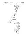
- FIG. 2is a pictorial perspective view showing the drilling of a hole in the scapula in connection with preparation of the scapula for the implant of the glenoid component in accordance with the present invention
- FIG. 3is a perspective view of a glenoid drill guide constructed in accordance with the present invention.
- FIG. 4is an enlarged side view of a portion of the glenoid drill guide
- FIG. 5is an enlarged cross-sectional view taken along line 5--5 of FIG. 3;
- FIG. 6is a cross-sectional view similar to FIG. 5, showing the component parts in another position;
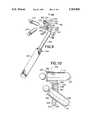
- FIG. 7is a perspective view of another glenoid drill guide constructed in accordance with the present invention.
- FIG. 8is a pictorial perspective showing an alternate glenoid component of a shoulder prosthesis being affixed to a scapula at an implant site;
- FIG. 9is a perspective view of still another glenoid drill guide constructed in accordance with the invention.
- FIG. 10is an enlarged cross-sectional view taken along line 10--10 of FIG. 9.
- a scapula 20has been prepared for the affixation of a glenoid component 22 of a shoulder prosthesis to the scapula 20 at the glenoid surface 24 of the scapula 20, which is the site for the glenoid component 22.
- glenoid component 22includes a glenoid member 30 extending in superior-inferior directions, that is, in upward and downward directions, and provides a bearing surface 32 for a humeral head (not shown).
- Glenoid component 22has an affixation surface 34 for affixing the glenoid component 22 to the scapula 20.
- An upper, or superior affixation peg 36 and a lower, or inferior affixation peg 38project from the affixation surface 34 to assist in securing the glenoid component 22 in place on the scapula 20.
- the lower affixation peg 38is oriented in an offset direction relative to the upper affixation peg 36, the offset direction making an acute angle A with the direction of the upper affixation peg 36. In the preferred orientation, angle A is about 30°.
- the scapula 20has been prepared to receive the affixation pegs 36 and 38 by drilling counterpart holes in the scapula 20 for reception of the pegs 36 and 38.
- a drill guide 40is constructed in accordance with the present invention and is shown in place against the scapula 20 for locating holes to be drilled in the scapula 20 with a drill 42, guided by the drill guide 40.
- drill guide 40is seen to include a guide block 50 and a handle 52 attached to the guide block 50 through a shaft 54 which extends between the guide block 50 and the handle 52.
- Guide block 50includes an obverse face 56 and a reverse face 58, an upper end 60 and a lower end 62 spaced from one another in longitudinal directions 63 and opposite side edges 64 and 66 spaced from one another in lateral directions 68.
- a first drill guide bore 70is located adjacent the upper end 60 and, as best seen in FIG. 5, extends through the guide block 50, from the obverse face 56 to the reverse face 58, along a first transverse direction 72, the transverse direction 72 being transverse to the longitudinal directions 63 and the lateral directions 68.
- a second drill guide bore 80is located adjacent the lower end 62 of the guide block 50, spaced longitudinally from the first drill guide bore 70, and extends through the guide block 50 from the obverse face 56 to the reverse face 58, along a second transverse direction 82, the transverse direction 82 being transverse to the longitudinal directions 63 and the lateral directions 68.
- the reverse face 58 of the guide block 50includes a surface 84 having a surface contour configuration generally complementary to the glenoid surface 24 of the scapula 20, at the site where the glenoid component 22 is to be affixed to the scapula 20.
- the reverse face 58is placed against the glenoid surface 24, as illustrated in FIG. 2, as well as in FIG. 5, by a surgeon 90 who holds the drill guide 40 by the handle 52, as seen in FIG. 2, and then guides the drill 42 through the first drill guide bore 70 to drill a first hole 92 (see FIG. 1) in the scapula 20.
- the guide block 50is provided with a sleeve portion 94 which extends from the obverse face 56 in a direction opposite to the first transverse direction 72 and extends the first drill guide bore 70 for increased support of the drill 42 in accurate alignment with first transverse direction 72.
- a locator pin 100is coupled with the guide block 50 to project from the reverse face 58, along the first transverse direction 72, as shown in FIG. 6.
- coupling meansare provided for selectively detachably coupling the locator pin 100 with the guide block 50, the coupling means including a generally cylindrical plug portion 102 on the locator pin 100 complementary to the first drill guide bore 70 for reception in the first drill guide bore 70 to attach the locator pin 100 to the guide block 50.
- the locator pin 100is advanced through the first drill guide bore 70 in the direction from the obverse face 56 toward the reverse face 58, along the first transverse direction 72, while the surface 84 of the guide block 50 is maintained seated against the glenoid surface 24.
- a flange 104 on the locator pin 100is seated within a complementary recess 106 at the drill guide bore 70 and the distal, or far end of the locator pin 100 extends into the first hole 92.
- a grip 108is provided at the proximal, or near end of the locator pin 100 for facilitating the selective attachment and detachment of the locator pin 100 and the guide block 50.
- the second drill guide bore 80is located in place accurately relative to the first hole 92 for the drilling of a second hole 110 (see FIG. 1) in the scapula 20.
- the surgeon 90guides the drill 42 through the second drill guide bore 80 to drill the second hole 110 (see FIG. 1) in the scapula 20, along the second transverse direction 82.
- the second transverse direction 82is oriented relative to the first transverse direction 72 at an acute angle B, with the first and second transverse directions 72 and 82 diverging in the direction from the obverse face 56 toward the reverse face 58.
- the longitudinal and lateral directions 63 and 68essentially lie in a plane P and the first transverse direction 72 extends essentially normal to the plane P.
- Acute angle Bessentially is the same as acute angle A.
- the size, orientation and placement of the first and second holes 92 and 110places the first and second holes 92 and 110 in an array corresponding to the first and second transverse directions 63 and 68, and complements the size, orientation and placement of the array of affixation pegs 36 and 38 of the glenoid component 22 for a high degree of accuracy in the location and affixation of the glenoid component 22 at the glenoid surface 24 of the scapula 20.
- FIG. 7another glenoid drill guide constructed in accordance with the invention is illustrated at 140 and is seen to include a first guide block 142 and a second guide block 144, with a common handle 146 between the guide blocks 142 and 144 and attached to the guide blocks 142 and 144 through corresponding respective shafts 147 and 148.
- Glenoid drill guide 140is used for the same purpose as glenoid drill guide 40, that is, the scapula 20 is to be prepared with two holes 92 and 110 sized, placed and oriented to receive the two affixation pegs 36 and 38 of the glenoid component 22, with the assistance of the drill guide 140; however, as is evident, the construction of the drill guide 140 differs in some respects from the construction of drill guide 40, with a concomitant difference in procedure.
- each guide block 142 and 144has a basic overall configuration very similar to guide block 50 in that each guide block 142 and 144 includes an obverse face 156 and a reverse face 158, an upper end 160 and a lower end 162 spaced from one another in longitudinal directions 163 and opposite side edges 164 and 166 spaced from one another in lateral directions 168.
- a first drill guide bore 170is located adjacent the upper end 160 of the first guide block 142 and extends through the first guide block 142, from the obverse face 156 to the reverse face 158, along a first transverse direction 172, the transverse direction 172 being transverse to the longitudinal directions 163 and the lateral directions 168.
- a second drill guide bore 180is located adjacent the lower end 162 of the second guide block 144 and extends through the second guide block 144 from the obverse face 156 to the reverse face 158, along a second transverse direction 182, the transverse direction 182 being transverse to the longitudinal directions 163 and the lateral directions 168.
- each guide block 142 and 144includes a surface 184 having a surface contour configuration generally complementary to the glenoid surface 24 of the scapula 20, at the site where the glenoid component 22 is to be affixed to the scapula 20.
- the reverse face 158 of the first guide block 142is placed against the glenoid surface 24, and the drill guide 140 is held in place by the handle 146, while a drill is guided through the first drill guide bore 170 to drill the first hole 92 in the scapula 20.
- the guide block 142is provided with a sleeve portion 190 which extends from the obverse face 156 in a direction opposite to the first transverse direction 172 and extends the first drill guide bore 170 for increased support of the drill in accurate alignment with first transverse direction 172.
- the first guide block 142is retracted from the scapula 20 and the second guide block 144 is placed against the scapula 20, with the reverse face 158 seated against the glenoid surface 24.
- a locator pin 200 integral with the second guide block 144 and projecting from the reverse face 158 of the second guide block 144is inserted into the first hole 92 so as to locate the second drill guide bore 180 in place for the drilling of the second hole 110 in the scapula 20.
- a drillis guided through the second drill guide bore 180 to drill the second hole 110 along the second transverse direction 182.
- the size, orientation and placement of the first and second holes 92 and 110complements the size, orientation and placement of the affixation pegs 36 and 38 of the glenoid component 22 for a high degree of accuracy in the location and affixation of the glenoid component 22 at the glenoid surface 24 of the scapula 20.
- locator pin 200already is integral with the second guide block 144, use of the drill guide 140, rather than the drill guide 40, eliminates the need to couple a separate locator pin with the guide block, as described above in connection with the use of drill guide 40. Further, the surgeon need hold only a single drill guide 140 which merely is reversed end-to-end during the procedure to accomplish the drilling of both holes 92 and 110.
- a scapula 220has been prepared for the affixation of a glenoid component 222 of a shoulder prosthesis to the scapula 220 at the glenoid surface 224 of the scapula 220, in very much the same manner as described above in connection with the first embodiment of the present invention.
- glenoid component 222has an affixation surface 234 for affixing the glenoid component 222 to the scapula 220, and an upper, or superior affixation peg 236 and a lower, or inferior affixation peg 238 project from the affixation surface 234 to assist in securing the glenoid component 222 in place on the scapula 220.
- glenoid component 222includes intermediate affixation pegs 239 placed intermediate the superior and inferior affixation pegs 236 and 238, extending generally parallel to the upper affixation peg 236, and spaced apart in the anterior-posterior direction.
- the scapula 220has been prepared to receive the affixation pegs 236, 238, and 239 by drilling counterpart holes in the scapula 220 for reception of the pegs 236, 238 and 239.
- a drill guide 240 constructed in accordance with the inventionis seen to include a guide block 250 and a handle 252 attached to the guide block 250 through a shaft 254 which extends between the guide block 250 and the handle 252.
- guide block 250includes an obverse face 256 and a reverse face 258, an upper end 260 and a lower end 262 spaced from one another in longitudinal directions 263 and opposite side edges 264 and 266 spaced from one another in lateral directions 268.
- a first drill guide bore 270is located adjacent the upper end 260 and, as best seen in FIG.
- a second drill guide bore 280is located adjacent the lower end 262 of the guide block 250 and extends through the guide block 250 from the obverse face 256 to the reverse face 258, along a second transverse direction 282, the transverse direction 282 being transverse to the longitudinal directions 263 and the lateral directions 268.
- Third and fourth drill guide bores 290 and 292are located each adjacent one of the side edges 264 and 266 of the guide block 250 and extend through the guide block 250, from the obverse face 256 to the reverse face 258, along corresponding transverse directions 294 and 296, essentially parallel to the first transverse direction 272.
- the reverse face 258 of the guide block 250includes a surface 298 having a surface contour configuration generally complementary to the glenoid surface 224 of the scapula 220, at the site where the glenoid component 222 is to be affixed to the scapula 220.
- the reverse face 258is placed against the glenoid surface 224, as described above, and the drill guide 240 is held by the handle 252, for guiding a drill through the first drill guide bore 270 to drill a first hole 300 in the scapula 220.
- the guide block 250is provided with a sleeve portion 302 which extends from the obverse face 258 in a direction opposite to the first transverse direction 272 and extends the first drill guide bore 270 for increased support of the drill in accurate alignment with first transverse direction 272.
- a locator pin 310is coupled with the guide block 250 to project from the reverse face 258, along the first transverse direction 272, as described above in connection with drill guide 40, and the locator pin 310 extending into the first hole 300.
- the second drill guide bore 280is located in place, relative to the first hole 300, for the drilling of a second hole 320 in the scapula 220, as described above.
- third and fourth holes 322 and 324are drilled in the scapula 220, with the third and fourth drill guide bores 290 and 292 serving to guide a drill to complete the drilling of the corresponding third and fourth holes 322 and 324.
- a second locator pin 312is inserted into the second drill guide bore 280 to couple the second locator pin 312 with the guide block 250, with the second locator pin 312 projecting from the guide block 250 in the second transverse direction 282, as illustrated in FIG. 10.
- the guide block 250With the reverse face 258 seated on the glenoid surface 224, and the locator pins 310 and 312 extending into the first hole 300 and the second hole 320, respectively, in the scapula 220, the guide block 250 is located and stabilized for accurate positioning of the third and fourth drill guide bores 290 and 292 and the concomitant accurate drilling of the third and fourth holes 322 and 324.
- the present inventionattains the several object and advantages summarized above, namely: Facilitates the location and drilling of holes in the natural bone at the site of a prosthetic implant for appropriate placement and seating of a prosthetic implant component having a specific array of affixation pegs, and especially in connection with the drilling of holes in a scapula for the implant of a glenoid component of a shoulder prosthesis; accommodates the array of affixation pegs in an effective and efficient manner, enabling a reduction in the time necessary to complete an implant procedure, to the benefit of the recipient of the implant; attains increased accuracy with increased ease; provides simplified instruments and procedures for attaining improved results; enables more economical manufacture of effective instruments having a rugged construction for exemplary performance over an extended service life.
Landscapes
- Health & Medical Sciences (AREA)
- Life Sciences & Earth Sciences (AREA)
- Veterinary Medicine (AREA)
- Animal Behavior & Ethology (AREA)
- Public Health (AREA)
- Surgery (AREA)
- Oral & Maxillofacial Surgery (AREA)
- Engineering & Computer Science (AREA)
- Biomedical Technology (AREA)
- Heart & Thoracic Surgery (AREA)
- General Health & Medical Sciences (AREA)
- Orthopedic Medicine & Surgery (AREA)
- Molecular Biology (AREA)
- Medical Informatics (AREA)
- Nuclear Medicine, Radiotherapy & Molecular Imaging (AREA)
- Dentistry (AREA)
- Cardiology (AREA)
- Transplantation (AREA)
- Vascular Medicine (AREA)
- Prostheses (AREA)
Abstract
Description
Claims (22)
Priority Applications (1)
| Application Number | Priority Date | Filing Date | Title |
|---|---|---|---|
| US08/669,078US5769856A (en) | 1996-06-24 | 1996-06-24 | Drill guide and implant method |
Applications Claiming Priority (1)
| Application Number | Priority Date | Filing Date | Title |
|---|---|---|---|
| US08/669,078US5769856A (en) | 1996-06-24 | 1996-06-24 | Drill guide and implant method |
Publications (1)
| Publication Number | Publication Date |
|---|---|
| US5769856Atrue US5769856A (en) | 1998-06-23 |
Family
ID=24684917
Family Applications (1)
| Application Number | Title | Priority Date | Filing Date |
|---|---|---|---|
| US08/669,078Expired - LifetimeUS5769856A (en) | 1996-06-24 | 1996-06-24 | Drill guide and implant method |
Country Status (1)
| Country | Link |
|---|---|
| US (1) | US5769856A (en) |
Cited By (107)
| Publication number | Priority date | Publication date | Assignee | Title |
|---|---|---|---|---|
| US5895390A (en)* | 1996-09-19 | 1999-04-20 | Biomet, Inc. | Pin placement guide used in making a bone entry hole for implantation of an intramedullary nail |
| US6022356A (en)* | 1998-03-18 | 2000-02-08 | Smith & Nephew, Inc. | Cruciate ligament reconstruction template |
| USD433506S (en)* | 1999-06-04 | 2000-11-07 | Asfora Wilson T | Double drill guide |
| US6312432B1 (en) | 2000-03-02 | 2001-11-06 | Nemco Medical, Inc. | Bone drill |
| US6342057B1 (en) | 2000-04-28 | 2002-01-29 | Synthes (Usa) | Remotely aligned surgical drill guide |
| US6347940B1 (en)* | 2000-08-22 | 2002-02-19 | Antonio Jose Gordils Wallis | Instrument and process for the minimum distance verification between two teeth for the placement of one or two bone integrated cylindrical or screwed type implants in dentistry |
| US6364910B1 (en)* | 2001-07-11 | 2002-04-02 | Biomet, Inc. | Method and apparatus for use of a glenoid component |
| US6379364B1 (en) | 2000-04-28 | 2002-04-30 | Synthes (Usa) | Dual drill guide for a locking bone plate |
| US20030055507A1 (en)* | 2001-09-11 | 2003-03-20 | Incumed, Incorporated | Modular prosthesis and insertion tool for bone structures |
| US6589281B2 (en) | 2001-01-16 | 2003-07-08 | Edward R. Hyde, Jr. | Transosseous core approach and instrumentation for joint replacement and repair |
| US20040024462A1 (en)* | 2002-04-12 | 2004-02-05 | Ferree Bret A. | Spacerless artificial disc replacements |
| US20040073311A1 (en)* | 2002-04-23 | 2004-04-15 | Ferree Bret A. | Two-component artificial disc replacements |
| US6758673B2 (en) | 2001-12-05 | 2004-07-06 | Ofir Fromovich | Periosteal distraction |
| US20040176773A1 (en)* | 2003-03-06 | 2004-09-09 | Rafail Zubok | Instrumentation and methods for use in implanting a cervical disc replacement device |
| EP1457159A1 (en)* | 2003-03-10 | 2004-09-15 | Tornier | Drill guide for positioning a glenoid implant |
| FR2852225A1 (en)* | 2004-03-11 | 2004-09-17 | Tornier Sa | Drill guide for bone joint surgery has convex plate to engage bone and guide insert with multiple bores to guide drill |
| US20040193272A1 (en)* | 2003-03-06 | 2004-09-30 | Rafail Zubok | Instrumentation and methods for use in implanting a cervical disc replacement device |
| US20040230197A1 (en)* | 2003-03-10 | 2004-11-18 | Alain Tornier | Ancillary tool for positioning a glenoid implant |
| US20040267270A1 (en)* | 2003-06-30 | 2004-12-30 | Jacobs Andrew M. | Implant stabilizing instrument, kit and method |
| US20050015093A1 (en)* | 2003-07-16 | 2005-01-20 | Suh Sean S. | Plating system with compression drill guide |
| US20050027301A1 (en)* | 2003-08-01 | 2005-02-03 | Pascal Stihl | Drill guide assembly for a bone fixation device |
| US6855150B1 (en)* | 2001-07-13 | 2005-02-15 | Timothy R. Linehan | Patellar trial and drill guide for use in knee replacement surgery |
| US20050038444A1 (en)* | 2003-08-13 | 2005-02-17 | Binder Lawrence J. | Quick-release drill-guide assembly for bone-plate |
| US20050055095A1 (en)* | 2001-07-16 | 2005-03-10 | Errico Joseph P. | Artificial intervertebral disc trials having a cylindrical engagement surface |
| US20050085820A1 (en)* | 2003-09-17 | 2005-04-21 | Corin Limited | Prosthetic cup |
| US20050119664A1 (en)* | 2000-03-17 | 2005-06-02 | Kinamed, Inc. | Marking template for installing a custom replacement device for resurfacing a femur and associated installation method |
| FR2865628A1 (en)* | 2004-02-02 | 2005-08-05 | Guy Bellier | Anterior cruciate ligament reconstructing system for knee, has screwdriver with oblong end with one part having cylindrical shape whose cross section has value lesser than that of another part to define shoulder |
| US20050228497A1 (en)* | 2002-04-23 | 2005-10-13 | Ferree Bret A | Artificial disc replacements with natural kinematics |
| US20060058809A1 (en)* | 2004-06-03 | 2006-03-16 | Zink Robert W | Method and apparatus for preparing a glenoid surface |
| US20060074430A1 (en)* | 2004-09-27 | 2006-04-06 | Deffenbaugh Daren L | Instrument for preparing an implant support surface and associated method |
| US20060161167A1 (en)* | 2005-01-18 | 2006-07-20 | Reese Myers | Acetabular instrument alignment guide |
| US20060189997A1 (en)* | 2005-02-10 | 2006-08-24 | Zimmer Spine, Inc. | All through one drill guide for cervical plating |
| US20060195194A1 (en)* | 2005-02-25 | 2006-08-31 | Gunther Stephen B | Shoulder implant for glenoid replacement and methods of use thereof |
| US20070038302A1 (en)* | 2005-08-15 | 2007-02-15 | Biomet Manufacturing Corp. | Method and apparatus for the preparation of an inlaid glenoid |
| US20070233108A1 (en)* | 2006-03-15 | 2007-10-04 | Stalcup Gregory C | Spine fixation device |
| US20070243498A1 (en)* | 2005-02-28 | 2007-10-18 | Wallis Antonio J G | Instrument and Process for the Minimum Distance Verification Between Teeth for the Placement of One or Two Bone Integrated Dental Implants |
| US20070298373A1 (en)* | 2006-06-22 | 2007-12-27 | W&H Dentalwerk Burmoos Gmbh | Implantological spacing device and implantological guide instrument for an implantological spacing device |
| US20080009874A1 (en)* | 2006-06-14 | 2008-01-10 | Biomet Manufacturing Corp. | Method and apparatus for reaming an acetabulum |
| US20080021564A1 (en)* | 2006-07-20 | 2008-01-24 | Gunther Stephen B | Humeral head resurfacing implant and methods of use thereof |
| US20080077152A1 (en)* | 2006-09-26 | 2008-03-27 | K2M, Inc. | Cervical drill guide apparatus |
| US20080082175A1 (en)* | 2006-09-29 | 2008-04-03 | Depuy Products, Inc. | Oseotomy protective cover |
| US20080241784A1 (en)* | 2005-08-19 | 2008-10-02 | Yoo-Jin Chung | Distance Measuring Apparatus for Dental Implant Insertion |
| US20100145351A1 (en)* | 2007-04-10 | 2010-06-10 | Ashman Richard B | Surgical Drill Guide For Shape Memory Clamps |
| US7736380B2 (en) | 2004-12-21 | 2010-06-15 | Rhausler, Inc. | Cervical plate system |
| US20100151411A1 (en)* | 2008-12-15 | 2010-06-17 | Straumann Holding Ag | Drill guide |
| US20100241235A1 (en)* | 2009-03-20 | 2010-09-23 | Depuy Products, Inc. | Glenoid Component for Use in Shoulder Arthroplasty and Associated Method of Implanting Same |
| US20100249938A1 (en)* | 2005-02-25 | 2010-09-30 | Gunther Stephen B | Methods and devices for less invasive glenoid replacement |
| US20100268345A1 (en)* | 2001-10-01 | 2010-10-21 | Spinecore, Inc. | Intervertebral spacer device |
| US20110029088A1 (en)* | 2009-07-31 | 2011-02-03 | Zimmer, Gmbh | Glenoid alignment tool |
| US20110040303A1 (en)* | 2009-08-11 | 2011-02-17 | The Cleveland Clinic Foundation | Method and apparatus for insertion of an elongate pin into a surface |
| US8029568B2 (en) | 2001-10-18 | 2011-10-04 | Spinecore, Inc. | Intervertebral spacer device having a slotted partial circular domed arch strip spring |
| US20120053589A1 (en)* | 2009-12-30 | 2012-03-01 | Linares Medical Devices, Llc | Combination male/female hip joint and installation kit |
| US20120143267A1 (en)* | 2010-10-29 | 2012-06-07 | The Cleveland Clinic Foundation | System and method for association of a guiding aid with a patient tissue |
| US8257341B1 (en) | 2008-05-27 | 2012-09-04 | Jack Maurice Fletcher | Inferior alveolar nerve block guide |
| WO2013142998A1 (en)* | 2012-03-28 | 2013-10-03 | Orthosoft Inc. | Glenoid implant surgery using patient specific instrumentation |
| US20140020333A1 (en)* | 2012-02-16 | 2014-01-23 | Adam T. Knight | Method and apparatus for an orthopedic fixation system |
| US8696680B2 (en) | 2009-08-11 | 2014-04-15 | The Cleveland Clinic Foundation | Method and apparatus for insertion of an elongate pin into a surface |
| US8915916B2 (en) | 2008-05-05 | 2014-12-23 | Mayo Foundation For Medical Education And Research | Intramedullary fixation device for small bone fractures |
| US8932299B2 (en) | 2010-06-18 | 2015-01-13 | Howmedica Osteonics Corp. | Patient-specific total hip arthroplasty |
| US9125749B2 (en) | 2010-10-22 | 2015-09-08 | Farid Amirouche | Patellar implant with variable weights for knee repair surgery |
| US20160030196A1 (en)* | 2013-03-27 | 2016-02-04 | Mobelife N.V. | Customized Surgical Guide |
| US20160089164A1 (en)* | 2005-03-31 | 2016-03-31 | Biomet Manufacturing, Llc. | Method and apparatus for performing a less invasive shoulder procedure |
| US20160199074A1 (en)* | 2015-01-12 | 2016-07-14 | Biomet Manufacturing, Llc | Augmented Glenoid and Method for Preparation |
| US9408646B2 (en) | 2003-09-03 | 2016-08-09 | DePuy Synthes Products, Inc. | Bone plate with captive clips |
| US9414870B2 (en) | 2003-09-03 | 2016-08-16 | DePuy Synthes Products, Inc. | Translatable carriage fixation system |
| US9579106B2 (en) | 2010-03-31 | 2017-02-28 | New York Society For The Relief Of The Ruptured And Crippled, Maintaining The Hospital For Special Surgery | Shoulder arthroplasty instrumentation |
| US9597190B2 (en) | 2015-01-15 | 2017-03-21 | DePuy Synthes Products, Inc. | Modular reverse shoulder orthopaedic implant and method of implanting the same |
| US9744057B2 (en) | 2000-05-09 | 2017-08-29 | Ben-Zion Karmon | Device to deliver flowable material to the sinus |
| US9750512B2 (en) | 2013-10-21 | 2017-09-05 | Zimmer Spine, Inc. | Drill guide for installing a bone plate |
| US9775716B2 (en) | 2013-03-11 | 2017-10-03 | Catalyst Orthoscience Inc. | Glenoid arthroplasty |
| US9814588B2 (en) | 2015-08-10 | 2017-11-14 | Catalyst Orthoscience Inc. | Glenoid arthroplasty with multi-directional fixation |
| US9814471B2 (en) | 2013-03-11 | 2017-11-14 | Catalyst Orthoscience Inc. | Glenoid arthroplasty and offset reamers |
| US9877735B2 (en) | 2010-10-29 | 2018-01-30 | The Cleveland Clinic Foundation | System and method for assisting with attachment of a stock implant to a patient tissue |
| US9877760B2 (en) | 2012-09-05 | 2018-01-30 | Signus Medizinetchnik GmbH | Implant for pelvic ring fractures |
| US9968456B2 (en) | 2013-03-15 | 2018-05-15 | Howmedica Osteonics Corporation | Customized acetabular cup positioning guide and method of generating and employing such a guide |
| US10405993B2 (en) | 2013-11-13 | 2019-09-10 | Tornier Sas | Shoulder patient specific instrument |
| US10456130B2 (en) | 2014-05-07 | 2019-10-29 | Biomedical Enterprises, Inc. | Method and apparatus for loading and implanting a shape memory implant |
| US10456131B2 (en) | 2014-05-07 | 2019-10-29 | Biomedical Enterprises, Inc. | Method and apparatus for loading and implanting a shape memory implant |
| US10492926B1 (en) | 2014-09-04 | 2019-12-03 | Shoulder Innovations, Inc. | Alignment guide for humeral or femoral stem replacement prostheses |
| US10595885B2 (en) | 2017-09-01 | 2020-03-24 | Arthrex, Inc. | Surgical drill guide |
| WO2020058633A1 (en) | 2018-09-20 | 2020-03-26 | Shoulder Friends Institute | Guide for positioning an orthopaedic guide pin on a bone structure |
| US20200107713A1 (en)* | 2018-10-08 | 2020-04-09 | Conmed Corporation | Arthroscopic instrument for improved viewing of gutter or offsetting of k-wire |
| US10716676B2 (en) | 2008-06-20 | 2020-07-21 | Tornier Sas | Method for modeling a glenoid surface of a scapula, apparatus for implanting a glenoid component of a shoulder prosthesis, and method for producing such a component |
| US10806591B2 (en)* | 2015-04-24 | 2020-10-20 | Biomet Manufacturing, Llc | Patient-specific augmented glenoid systems and methods |
| US10820902B2 (en) | 2015-09-03 | 2020-11-03 | Biomedical Enterprises, Inc. | Elastic orthopedic implant and method of manufacturing thereof |
| US10959742B2 (en) | 2017-07-11 | 2021-03-30 | Tornier, Inc. | Patient specific humeral cutting guides |
| US10973646B2 (en) | 2013-03-11 | 2021-04-13 | Catalyst Orthoscience Inc. | Stabilized drill guide |
| US11007064B2 (en) | 2015-08-10 | 2021-05-18 | Catalyst Orthoscience Inc. | Arthroplasty prostheses with multi-axis fixation |
| US11007063B2 (en) | 2013-03-11 | 2021-05-18 | Catalyst Orthoscience Inc. | Offset reamers |
| US11045289B2 (en) | 2015-12-29 | 2021-06-29 | Ben Zion Karmon | Devices and methods for elevating the Schneiderian membrane |
| US11065016B2 (en) | 2015-12-16 | 2021-07-20 | Howmedica Osteonics Corp. | Patient specific instruments and methods for joint prosthesis |
| US11065125B2 (en) | 2017-04-14 | 2021-07-20 | Shoulder Innovations, Inc. | Total shoulder prosthesis having inset glenoid implant convertible from anatomic to reverse |
| US20210338456A1 (en)* | 2018-10-02 | 2021-11-04 | Tornier, Inc. | Metaphyseal referencing technique and instrument |
| US11166733B2 (en) | 2017-07-11 | 2021-11-09 | Howmedica Osteonics Corp. | Guides and instruments for improving accuracy of glenoid implant placement |
| US11224446B2 (en)* | 2019-06-20 | 2022-01-18 | Imam Abdulrahman Bin Faisal University | Supracondylar bullet sleeve |
| US11344423B1 (en) | 2009-03-05 | 2022-05-31 | Howmedica Osteonics Corp. | Glenoid implant anchor post |
| US11523820B2 (en) | 2020-01-29 | 2022-12-13 | DePuy Synthes Products, Inc. | Shape memory implants and a method and apparatus for the loading and implanting thereof |
| USD977643S1 (en) | 2019-03-12 | 2023-02-07 | Shoulder Innovations, Inc. | Humeral stem implant |
| US20230038980A1 (en)* | 2020-03-25 | 2023-02-09 | Howmedica Osteonics Corp. | Metaphyseal referencing technique and instrument |
| US20230090753A1 (en) | 2019-03-11 | 2023-03-23 | Shoulder Innovations, Inc. | Total reverse shoulder systems and methods |
| US20230233217A1 (en)* | 2022-01-26 | 2023-07-27 | Mayo Foundation For Medical Education And Research | Surgical guide instrument devices and methods |
| US11819380B2 (en) | 2016-10-13 | 2023-11-21 | Ben Zion Karmon | Devices for tissue augmentation |
| US11957595B2 (en) | 2005-02-25 | 2024-04-16 | Shoulder Innovations, Inc. | Methods and devices for less invasive glenoid replacement |
| US12042386B2 (en) | 2020-01-29 | 2024-07-23 | DePuy Synthes Products, Inc. | Shape memory implants and methods and apparatus for the loading and implanting thereof |
| US12138172B2 (en) | 2018-04-30 | 2024-11-12 | Shoulder Innovations, Inc. | Inset/onlay glenoid, porous coated convertible glenoid, and humeral heads with textured undersides |
| US12193939B2 (en) | 2017-12-29 | 2025-01-14 | Howmedica Osteonics Corp. | Patient specific humeral implant components |
| US12409038B2 (en) | 2018-02-06 | 2025-09-09 | Howmedica Osteonics Corp. | Method for manufacturing a patient-specific prosthesis for a fractured long bone |
Citations (7)
| Publication number | Priority date | Publication date | Assignee | Title |
|---|---|---|---|---|
| DE2041929A1 (en)* | 1969-08-25 | 1971-03-11 | Nat Res Dev | Prosthetic shoulder joint |
| USD284889S (en) | 1983-10-19 | 1986-07-29 | Howmedica, Inc. | Combined acetabulum sizer and drill guide |
| US5030219A (en)* | 1990-01-22 | 1991-07-09 | Boehringer Mannheim Corporation | Glenoid component installation tools |
| US5080673A (en)* | 1988-02-03 | 1992-01-14 | Intermedics Orthopedics, Inc. | Glenoid prosthesis and method of use |
| US5112336A (en)* | 1991-05-14 | 1992-05-12 | Intermedics Orthopedics, Inc. | Drill guide and template for prosthetic devices |
| EP0499475A2 (en)* | 1991-02-14 | 1992-08-19 | SMITH & NEPHEW RICHARDS, INC. | Acetabular prosthesis with anchoring pegs |
| US5462550A (en)* | 1992-08-13 | 1995-10-31 | Zimmer, Inc. | Alignment guide and method |
- 1996
- 1996-06-24USUS08/669,078patent/US5769856A/ennot_activeExpired - Lifetime
Patent Citations (7)
| Publication number | Priority date | Publication date | Assignee | Title |
|---|---|---|---|---|
| DE2041929A1 (en)* | 1969-08-25 | 1971-03-11 | Nat Res Dev | Prosthetic shoulder joint |
| USD284889S (en) | 1983-10-19 | 1986-07-29 | Howmedica, Inc. | Combined acetabulum sizer and drill guide |
| US5080673A (en)* | 1988-02-03 | 1992-01-14 | Intermedics Orthopedics, Inc. | Glenoid prosthesis and method of use |
| US5030219A (en)* | 1990-01-22 | 1991-07-09 | Boehringer Mannheim Corporation | Glenoid component installation tools |
| EP0499475A2 (en)* | 1991-02-14 | 1992-08-19 | SMITH & NEPHEW RICHARDS, INC. | Acetabular prosthesis with anchoring pegs |
| US5112336A (en)* | 1991-05-14 | 1992-05-12 | Intermedics Orthopedics, Inc. | Drill guide and template for prosthetic devices |
| US5462550A (en)* | 1992-08-13 | 1995-10-31 | Zimmer, Inc. | Alignment guide and method |
Non-Patent Citations (12)
| Title |
|---|
| Biomet, Inc. "Bio-Modular Total Shoulder," (1995), Steps 8-9B. |
| Biomet, Inc. Bio Modular Total Shoulder, (1995), Steps 8 9B.* |
| DePuy Inc. "Global Total Shoulder Arthroplasty System," (1994), pp. 18-19. |
| DePuy Inc. Components and Instruments, (date unknown).* |
| DePuy Inc. Global Total Shoulder Arthroplasty System, (1994), pp. 18 19.* |
| Intermedics Orthopedics, Inc. "The Intermedics Select Shoulder System," (1992), pp. 22-23. |
| Intermedics Orthopedics, Inc. The Intermedics Select Shoulder System, (1992), pp. 22 23.* |
| Morrey, Bernard. Joint Replacement Arthroplasty, (1991), Churchill Livingstone, p. 432.* |
| Petty, William. "Total Joint Replacement," (1991), W.B. Saunders Company, p. 630-631. |
| Petty, William. Total Joint Replacement, (1991), W.B. Saunders Company, p. 630 631.* |
| Smith & Nephew Richards, Inc. "The Cofield Total Shoulder System," (date unknown), Fig. 13-16. |
| Smith & Nephew Richards, Inc. The Cofield Total Shoulder System, (date unknown), Fig. 13 16.* |
Cited By (273)
| Publication number | Priority date | Publication date | Assignee | Title |
|---|---|---|---|---|
| US5895390A (en)* | 1996-09-19 | 1999-04-20 | Biomet, Inc. | Pin placement guide used in making a bone entry hole for implantation of an intramedullary nail |
| US6022356A (en)* | 1998-03-18 | 2000-02-08 | Smith & Nephew, Inc. | Cruciate ligament reconstruction template |
| USD433506S (en)* | 1999-06-04 | 2000-11-07 | Asfora Wilson T | Double drill guide |
| US6312432B1 (en) | 2000-03-02 | 2001-11-06 | Nemco Medical, Inc. | Bone drill |
| US20050119664A1 (en)* | 2000-03-17 | 2005-06-02 | Kinamed, Inc. | Marking template for installing a custom replacement device for resurfacing a femur and associated installation method |
| US8771281B2 (en)* | 2000-03-17 | 2014-07-08 | Kinamed, Inc. | Marking template for installing a custom replacement device for resurfacing a femur and associated installation method |
| US8961529B2 (en) | 2000-03-17 | 2015-02-24 | Kinamed, Inc. | Marking template for installing a custom replacement device for resurfacing a femur and associated installation method |
| US8936602B2 (en)* | 2000-03-17 | 2015-01-20 | Kinamed, Inc. | Marking template for installing a custom replacement device for resurfacing a femur and associated installation method |
| US20080215059A1 (en)* | 2000-03-17 | 2008-09-04 | Kinamed, Inc. | Marking template for installing a custom replacement device for resurfacing a femur and associated installation method |
| US9393032B2 (en)* | 2000-03-17 | 2016-07-19 | Kinamed, Inc. | Marking template for installing a custom replacement device for resurfacing a femur and associated installation method |
| US7517365B2 (en)* | 2000-03-17 | 2009-04-14 | Kinamed, Inc. | Marking template for installing a custom replacement device for resurfacing a femur and associated installation method |
| US8936601B2 (en)* | 2000-03-17 | 2015-01-20 | Kinamed, Inc. | Marking template for installing a custom replacement device for resurfacing a femur and associated installation method |
| US7935150B2 (en) | 2000-03-17 | 2011-05-03 | Kinamed, Inc. | Marking template for installing a custom replacement device for resurfacing a femur and associated installation method |
| US20110276145A1 (en)* | 2000-03-17 | 2011-11-10 | Roger Carignan | Marking template for installing a custom replacement device for resurfacing a femur and associated installation method |
| US8419741B2 (en) | 2000-03-17 | 2013-04-16 | Kinamed, Inc. | Marking template for installing a custom replacement device for resurfacing a femur and associated installation method |
| US6379364B1 (en) | 2000-04-28 | 2002-04-30 | Synthes (Usa) | Dual drill guide for a locking bone plate |
| US6342057B1 (en) | 2000-04-28 | 2002-01-29 | Synthes (Usa) | Remotely aligned surgical drill guide |
| US9744057B2 (en) | 2000-05-09 | 2017-08-29 | Ben-Zion Karmon | Device to deliver flowable material to the sinus |
| US6347940B1 (en)* | 2000-08-22 | 2002-02-19 | Antonio Jose Gordils Wallis | Instrument and process for the minimum distance verification between two teeth for the placement of one or two bone integrated cylindrical or screwed type implants in dentistry |
| US20060142865A1 (en)* | 2001-01-16 | 2006-06-29 | Hyde Edward R Jr | Transosseous core approach and instrumentation for joint replacement and repair |
| US6984248B2 (en) | 2001-01-16 | 2006-01-10 | Hyde Jr Edward R | Transosseous core approach and instrumentation for joint replacement and repair |
| US6783548B2 (en) | 2001-01-16 | 2004-08-31 | Edward R. Hyde, Jr. | Modular joint prostheses |
| US6716249B2 (en) | 2001-01-16 | 2004-04-06 | Edward R. Hyde | Joint prosthesis and method of implantation |
| US6589281B2 (en) | 2001-01-16 | 2003-07-08 | Edward R. Hyde, Jr. | Transosseous core approach and instrumentation for joint replacement and repair |
| US6364910B1 (en)* | 2001-07-11 | 2002-04-02 | Biomet, Inc. | Method and apparatus for use of a glenoid component |
| US6855150B1 (en)* | 2001-07-13 | 2005-02-15 | Timothy R. Linehan | Patellar trial and drill guide for use in knee replacement surgery |
| US8357167B2 (en) | 2001-07-16 | 2013-01-22 | Spinecore, Inc. | Artificial intervertebral disc trials with baseplates having inward tool engagement holes |
| US20100174371A9 (en)* | 2001-07-16 | 2010-07-08 | Errico Joseph P | Artificial intervertebral disc trials having a cylindrical engagement surface |
| US20050055095A1 (en)* | 2001-07-16 | 2005-03-10 | Errico Joseph P. | Artificial intervertebral disc trials having a cylindrical engagement surface |
| US20030055507A1 (en)* | 2001-09-11 | 2003-03-20 | Incumed, Incorporated | Modular prosthesis and insertion tool for bone structures |
| US8092539B2 (en) | 2001-10-01 | 2012-01-10 | Spinecore, Inc. | Intervertebral spacer device having a belleville washer with concentric grooves |
| US20100268345A1 (en)* | 2001-10-01 | 2010-10-21 | Spinecore, Inc. | Intervertebral spacer device |
| US8029568B2 (en) | 2001-10-18 | 2011-10-04 | Spinecore, Inc. | Intervertebral spacer device having a slotted partial circular domed arch strip spring |
| US6758673B2 (en) | 2001-12-05 | 2004-07-06 | Ofir Fromovich | Periosteal distraction |
| US20080027548A9 (en)* | 2002-04-12 | 2008-01-31 | Ferree Bret A | Spacerless artificial disc replacements |
| US8679182B2 (en) | 2002-04-12 | 2014-03-25 | Spinecore, Inc. | Spacerless artificial disc replacements |
| US8801789B2 (en) | 2002-04-12 | 2014-08-12 | Spinecore, Inc. | Two-component artificial disc replacements |
| US10271956B2 (en) | 2002-04-12 | 2019-04-30 | Spinecore, Inc. | Spacerless artificial disc replacements |
| US20040024462A1 (en)* | 2002-04-12 | 2004-02-05 | Ferree Bret A. | Spacerless artificial disc replacements |
| US8470041B2 (en) | 2002-04-12 | 2013-06-25 | Spinecore, Inc. | Two-component artificial disc replacements |
| US9198773B2 (en) | 2002-04-12 | 2015-12-01 | Spinecore, Inc. | Spacerless artificial disc replacements |
| US8277507B2 (en) | 2002-04-12 | 2012-10-02 | Spinecore, Inc. | Spacerless artificial disc replacements |
| US20100241233A1 (en)* | 2002-04-12 | 2010-09-23 | Spinecore, Inc. | Spacerless artificial disc replacements |
| US10786363B2 (en) | 2002-04-12 | 2020-09-29 | Spinecore, Inc. | Spacerless artificial disc replacements |
| US9168146B2 (en) | 2002-04-23 | 2015-10-27 | Spinecore, Inc. | Artificial disc replacements with natural kinematics |
| US8038713B2 (en) | 2002-04-23 | 2011-10-18 | Spinecore, Inc. | Two-component artificial disc replacements |
| US9572679B2 (en) | 2002-04-23 | 2017-02-21 | Spinecore, Inc. | Artificial disc replacements with natural kinematics |
| US20040073311A1 (en)* | 2002-04-23 | 2004-04-15 | Ferree Bret A. | Two-component artificial disc replacements |
| US8784492B2 (en) | 2002-04-23 | 2014-07-22 | Spinecore, Inc. | Artificial disc replacements with natural kinematics |
| US9877841B2 (en) | 2002-04-23 | 2018-01-30 | Spinecore, Inc. | Artificial disc replacements with natural kinematics |
| US10299933B2 (en) | 2002-04-23 | 2019-05-28 | Spinecore, Inc. | Artificial disc replacements with natural kinematics |
| US8366772B2 (en) | 2002-04-23 | 2013-02-05 | Spinecore, Inc. | Artificial disc replacements with natural kinematics |
| US20050228497A1 (en)* | 2002-04-23 | 2005-10-13 | Ferree Bret A | Artificial disc replacements with natural kinematics |
| US8936640B2 (en) | 2003-03-06 | 2015-01-20 | Spinecore, Inc. | Cervical disc replacement |
| US20100087870A1 (en)* | 2003-03-06 | 2010-04-08 | Spinecore, Inc. | Instrumentation and methods for use in implanting a cervical disc replacement device |
| US8109979B2 (en) | 2003-03-06 | 2012-02-07 | Spinecore, Inc. | Instrumentation and methods for use in implanting a cervical disc replacement device |
| US9603716B2 (en) | 2003-03-06 | 2017-03-28 | Spinecore, Inc. | Intervertebral disc replacement |
| US11382762B2 (en) | 2003-03-06 | 2022-07-12 | Howmedica Osteonics Corp. | Instrumentation and methods for use in implanting a cervical disc replacement device |
| US20040193272A1 (en)* | 2003-03-06 | 2004-09-30 | Rafail Zubok | Instrumentation and methods for use in implanting a cervical disc replacement device |
| US9028552B2 (en) | 2003-03-06 | 2015-05-12 | Spinecore, Inc. | Cervical disc replacement |
| US20040176773A1 (en)* | 2003-03-06 | 2004-09-09 | Rafail Zubok | Instrumentation and methods for use in implanting a cervical disc replacement device |
| US8961608B2 (en) | 2003-03-06 | 2015-02-24 | Spinecore, Inc. | Intervertebral disc replacement |
| US10159578B2 (en) | 2003-03-06 | 2018-12-25 | Spinecore, Inc. | Instrumentation and methods for use in implanting a cervical disc replacement device |
| US10835385B2 (en) | 2003-03-06 | 2020-11-17 | Howmedica Osteonics Corp. | Instrumentation and methods for use in implanting a cervical disc replacement device |
| US7618439B2 (en) | 2003-03-06 | 2009-11-17 | Spinecore, Inc. | Instrumentation and methods for use in implanting a cervical disc replacement device |
| US7637911B2 (en) | 2003-03-06 | 2009-12-29 | Spinecore, Inc. | Instrumentation and methods for use in implanting a cervical disc replacement device |
| US7641665B2 (en) | 2003-03-06 | 2010-01-05 | Spinecore, Inc. | Instrumentation and methods for use in implementing a cervical disc replacement device |
| US8231628B2 (en) | 2003-03-06 | 2012-07-31 | Spinecore, Inc. | Instrumentation and methods for use in implanting a cervical disc replacement device |
| US7641654B2 (en) | 2003-03-06 | 2010-01-05 | Spinecore, Inc. | Instrumentation and methods for use in implanting a cervical disc replacement device |
| US7648511B2 (en)* | 2003-03-06 | 2010-01-19 | Spinecore, Inc. | Instrumentation and methods for use in implanting a cervical disc replacement device |
| US7662182B2 (en) | 2003-03-06 | 2010-02-16 | Spinecore, Inc. | Instrumentation and methods for use in implanting a cervical disc replacement device |
| US20040176778A1 (en)* | 2003-03-06 | 2004-09-09 | Rafail Zubok | Instrumentation and methods for use in implanting a cervical disc replacement device |
| US7674292B2 (en) | 2003-03-06 | 2010-03-09 | Spinecore, Inc. | Instrumentation and methods for use in implanting a cervical disc replacement device |
| US20050240271A1 (en)* | 2003-03-06 | 2005-10-27 | Spinecore, Inc. | Cervical disc replacement |
| US20100076506A1 (en)* | 2003-03-06 | 2010-03-25 | Spinecore, Inc. | Instrumentation and methods for use in implanting a cervical disc replacement device |
| US10369005B2 (en) | 2003-03-06 | 2019-08-06 | Spinecore, Inc. | Cervical disc replacement |
| US20050240272A1 (en)* | 2003-03-06 | 2005-10-27 | Spinecore, Inc. | Cervical disc replacement |
| US20050240270A1 (en)* | 2003-03-06 | 2005-10-27 | Spinecore, Inc. | Cervical disc replacement |
| US20100100186A1 (en)* | 2003-03-06 | 2010-04-22 | Spinecore, Inc. | Instrumentation and methods for use in implanting a cervical disc replacement device |
| US7708780B2 (en) | 2003-03-06 | 2010-05-04 | Spinecore, Inc. | Instrumentation and methods for use in implanting a cervical disc replacement device |
| US8435297B2 (en) | 2003-03-06 | 2013-05-07 | Spinecore, Inc. | Intervertebral disc replacement |
| US20040176772A1 (en)* | 2003-03-06 | 2004-09-09 | Rafail Zubok | Instrumentation and methods for use in implanting a cervical disc replacement device |
| US20050071013A1 (en)* | 2003-03-06 | 2005-03-31 | Spinecore, Inc. | Instrumentation and methods for use in implanting a cervical disc replacement device |
| US20040176774A1 (en)* | 2003-03-06 | 2004-09-09 | Rafail Zubok | Instrumentation and methods for use in implanting a cervical disc replacement device |
| US20040176777A1 (en)* | 2003-03-06 | 2004-09-09 | Rafail Zubok | Instrumentation and methods for use in implanting a cervical disc replacement device |
| US20040230197A1 (en)* | 2003-03-10 | 2004-11-18 | Alain Tornier | Ancillary tool for positioning a glenoid implant |
| EP2160985A1 (en)* | 2003-03-10 | 2010-03-10 | Tornier | Drill guide for positioning a glenoid implant |
| US7887544B2 (en) | 2003-03-10 | 2011-02-15 | Tornier Sas | Ancillary tool for positioning a glenoid implant |
| US8187282B2 (en) | 2003-03-10 | 2012-05-29 | Tornier Sas | Ancillary tool for positioning a glenoid implant |
| FR2852224A1 (en)* | 2003-03-10 | 2004-09-17 | Tornier Sa | GLENOIDIAN IMPLANT PLANT ANCILLARY |
| EP1457159A1 (en)* | 2003-03-10 | 2004-09-15 | Tornier | Drill guide for positioning a glenoid implant |
| US20040267270A1 (en)* | 2003-06-30 | 2004-12-30 | Jacobs Andrew M. | Implant stabilizing instrument, kit and method |
| US7473259B2 (en)* | 2003-06-30 | 2009-01-06 | Depuy Products, Inc. | Implant stabilizing instrument, kit and method |
| US20050015092A1 (en)* | 2003-07-16 | 2005-01-20 | Rathbun David S. | Plating system with multiple function drill guide |
| US20050015093A1 (en)* | 2003-07-16 | 2005-01-20 | Suh Sean S. | Plating system with compression drill guide |
| US7731721B2 (en) | 2003-07-16 | 2010-06-08 | Synthes Usa, Llc | Plating system with multiple function drill guide |
| US20050027301A1 (en)* | 2003-08-01 | 2005-02-03 | Pascal Stihl | Drill guide assembly for a bone fixation device |
| US7081119B2 (en) | 2003-08-01 | 2006-07-25 | Hfsc Company | Drill guide assembly for a bone fixation device |
| US20050038444A1 (en)* | 2003-08-13 | 2005-02-17 | Binder Lawrence J. | Quick-release drill-guide assembly for bone-plate |
| US7357804B2 (en) | 2003-08-13 | 2008-04-15 | Synthes (U.S.A.) | Quick-release drill-guide assembly for bone-plate |
| US9408646B2 (en) | 2003-09-03 | 2016-08-09 | DePuy Synthes Products, Inc. | Bone plate with captive clips |
| US10368927B2 (en) | 2003-09-03 | 2019-08-06 | DePuy Synthes Products, Inc. | Bone plate with captive clips |
| US9414870B2 (en) | 2003-09-03 | 2016-08-16 | DePuy Synthes Products, Inc. | Translatable carriage fixation system |
| US20050085820A1 (en)* | 2003-09-17 | 2005-04-21 | Corin Limited | Prosthetic cup |
| US7641656B2 (en)* | 2003-09-17 | 2010-01-05 | Corin Limited | Prosthetic cup |
| FR2865628A1 (en)* | 2004-02-02 | 2005-08-05 | Guy Bellier | Anterior cruciate ligament reconstructing system for knee, has screwdriver with oblong end with one part having cylindrical shape whose cross section has value lesser than that of another part to define shoulder |
| FR2852225A1 (en)* | 2004-03-11 | 2004-09-17 | Tornier Sa | Drill guide for bone joint surgery has convex plate to engage bone and guide insert with multiple bores to guide drill |
| US20080027451A1 (en)* | 2004-06-03 | 2008-01-31 | Zimmer Technology, Inc. | Method and apparatus for preparing a glenoid surface |
| US7294133B2 (en) | 2004-06-03 | 2007-11-13 | Zimmer Technology, Inc. | Method and apparatus for preparing a glenoid surface |
| US20060058809A1 (en)* | 2004-06-03 | 2006-03-16 | Zink Robert W | Method and apparatus for preparing a glenoid surface |
| US20060074430A1 (en)* | 2004-09-27 | 2006-04-06 | Deffenbaugh Daren L | Instrument for preparing an implant support surface and associated method |
| US8790350B2 (en) | 2004-09-27 | 2014-07-29 | DePuy Synthes Products, LLC | Instrument for preparing an implant support surface and associated method |
| US7927335B2 (en)* | 2004-09-27 | 2011-04-19 | Depuy Products, Inc. | Instrument for preparing an implant support surface and associated method |
| US20110144651A1 (en)* | 2004-09-27 | 2011-06-16 | Depuy Products, Inc. | Instrument for preparing an implant support surface and associated method |
| US7736380B2 (en) | 2004-12-21 | 2010-06-15 | Rhausler, Inc. | Cervical plate system |
| US20060161167A1 (en)* | 2005-01-18 | 2006-07-20 | Reese Myers | Acetabular instrument alignment guide |
| US8109934B2 (en) | 2005-02-10 | 2012-02-07 | Zimmer Spine, Inc. | All through one drill guide for cervical plating |
| US20060189997A1 (en)* | 2005-02-10 | 2006-08-24 | Zimmer Spine, Inc. | All through one drill guide for cervical plating |
| US12089859B2 (en) | 2005-02-25 | 2024-09-17 | Shoulder Innovations, Inc. | Methods for less invasive glenoid replacement |
| US20060195194A1 (en)* | 2005-02-25 | 2006-08-31 | Gunther Stephen B | Shoulder implant for glenoid replacement and methods of use thereof |
| US10779952B2 (en) | 2005-02-25 | 2020-09-22 | Shoulder Innovations, Inc. | Methods and devices for less invasive glenoid replacement |
| US20100249938A1 (en)* | 2005-02-25 | 2010-09-30 | Gunther Stephen B | Methods and devices for less invasive glenoid replacement |
| US8007538B2 (en) | 2005-02-25 | 2011-08-30 | Shoulder Innovations, Llc | Shoulder implant for glenoid replacement |
| US8038719B2 (en) | 2005-02-25 | 2011-10-18 | Shoulder Innovations, Llc | Methods for less invasive glenoid replacement |
| US20110112648A1 (en)* | 2005-02-25 | 2011-05-12 | Shoulder Innovations, LLC. | Methods for less invasive glenoid replacement |
| US11957595B2 (en) | 2005-02-25 | 2024-04-16 | Shoulder Innovations, Inc. | Methods and devices for less invasive glenoid replacement |
| US8778028B2 (en) | 2005-02-25 | 2014-07-15 | Shoulder Innovations, Inc. | Methods and devices for less invasive glenoid replacement |
| US11992415B2 (en) | 2005-02-25 | 2024-05-28 | Shoulder Innovations, Inc. | Methods and devices for less invasive glenoid replacement |
| US11696772B2 (en) | 2005-02-25 | 2023-07-11 | Shoulder Innovations, Inc. | Methods for less invasive glenoid replacement |
| US20100087877A1 (en)* | 2005-02-25 | 2010-04-08 | Shoulder Innovations, Llc | Methods of implanting glenoid inlay |
| US9610166B2 (en) | 2005-02-25 | 2017-04-04 | Shoulder Innovations, Llc | Methods and devices for less invasive glenoid replacement |
| US10786265B2 (en) | 2005-02-25 | 2020-09-29 | Shoulder Innovations, Inc. | Methods for less invasive glenoid replacement |
| US9693784B2 (en) | 2005-02-25 | 2017-07-04 | Shoulder Innovations, Llc | Methods for less invasive glenoid replacement |
| US20100087876A1 (en)* | 2005-02-25 | 2010-04-08 | Shoulder Innovations, Llc | Methods for less invasive glenoid replacement |
| US7874838B2 (en)* | 2005-02-28 | 2011-01-25 | Innovative Implant Technology, Llc | Instrument and process for the minimum distance verification between teeth for the placement of one or two bone integrated dental implants |
| US20070243498A1 (en)* | 2005-02-28 | 2007-10-18 | Wallis Antonio J G | Instrument and Process for the Minimum Distance Verification Between Teeth for the Placement of One or Two Bone Integrated Dental Implants |
| US20160089164A1 (en)* | 2005-03-31 | 2016-03-31 | Biomet Manufacturing, Llc. | Method and apparatus for performing a less invasive shoulder procedure |
| US20070038302A1 (en)* | 2005-08-15 | 2007-02-15 | Biomet Manufacturing Corp. | Method and apparatus for the preparation of an inlaid glenoid |
| US20080241784A1 (en)* | 2005-08-19 | 2008-10-02 | Yoo-Jin Chung | Distance Measuring Apparatus for Dental Implant Insertion |
| US20070233108A1 (en)* | 2006-03-15 | 2007-10-04 | Stalcup Gregory C | Spine fixation device |
| US7670343B2 (en) | 2006-06-14 | 2010-03-02 | Biomet Manufacturing Corp. | Method and apparatus for reaming an acetabulum |
| US20080009874A1 (en)* | 2006-06-14 | 2008-01-10 | Biomet Manufacturing Corp. | Method and apparatus for reaming an acetabulum |
| US20070298373A1 (en)* | 2006-06-22 | 2007-12-27 | W&H Dentalwerk Burmoos Gmbh | Implantological spacing device and implantological guide instrument for an implantological spacing device |
| US20080021564A1 (en)* | 2006-07-20 | 2008-01-24 | Gunther Stephen B | Humeral head resurfacing implant and methods of use thereof |
| US20100274360A1 (en)* | 2006-07-20 | 2010-10-28 | Gunther Stephen B | Humeral head resurfacing implant and methods of use thereof |
| US20080077152A1 (en)* | 2006-09-26 | 2008-03-27 | K2M, Inc. | Cervical drill guide apparatus |
| US8282642B2 (en) | 2006-09-26 | 2012-10-09 | K2M, Inc. | Cervical drill guide apparatus |
| US20080082175A1 (en)* | 2006-09-29 | 2008-04-03 | Depuy Products, Inc. | Oseotomy protective cover |
| US8821496B2 (en) | 2006-09-29 | 2014-09-02 | DePuy Synthes Products, LLC | Osteotomy protective cover |
| US10363146B2 (en) | 2006-09-29 | 2019-07-30 | DePuy Synthes Products, Inc. | Osteotomy protective cover |
| US9925065B2 (en) | 2006-09-29 | 2018-03-27 | DePuy Synthes Products, Inc. | Method of using an osteotomy protective cover |
| US20100145351A1 (en)* | 2007-04-10 | 2010-06-10 | Ashman Richard B | Surgical Drill Guide For Shape Memory Clamps |
| US8241297B2 (en)* | 2007-04-10 | 2012-08-14 | Intelifuse, Inc. | Surgical drill guide for shape memory clamps |
| US8915916B2 (en) | 2008-05-05 | 2014-12-23 | Mayo Foundation For Medical Education And Research | Intramedullary fixation device for small bone fractures |
| US8257341B1 (en) | 2008-05-27 | 2012-09-04 | Jack Maurice Fletcher | Inferior alveolar nerve block guide |
| US10716676B2 (en) | 2008-06-20 | 2020-07-21 | Tornier Sas | Method for modeling a glenoid surface of a scapula, apparatus for implanting a glenoid component of a shoulder prosthesis, and method for producing such a component |
| US11432930B2 (en) | 2008-06-20 | 2022-09-06 | Tornier Sas | Method for modeling a glenoid surface of a scapula, apparatus for implanting a glenoid component of a shoulder prosthesis, and method for producing such a component |
| US12268608B2 (en) | 2008-06-20 | 2025-04-08 | Tornier Sas | Method for modeling a glenoid surface of a scapula, apparatus for implanting a glenoid component of a shoulder prosthesis, and method for producing such a component |
| US12156815B2 (en) | 2008-06-20 | 2024-12-03 | Tornier Sas | Method for modeling a glenoid surface of a scapula, apparatus for implanting a glenoid component of a shoulder prosthesis, and method for producing such a component |
| US8708699B2 (en)* | 2008-12-15 | 2014-04-29 | Straumann Holding Ag | Drill guide |
| US20100151411A1 (en)* | 2008-12-15 | 2010-06-17 | Straumann Holding Ag | Drill guide |
| US12245947B2 (en) | 2009-03-05 | 2025-03-11 | Howmedica Osteonics Corp. | Glenoid implant anchor post |
| US11865012B2 (en) | 2009-03-05 | 2024-01-09 | Howmedica Osteonics Corp. | Glenoid implant anchor post |
| US11344423B1 (en) | 2009-03-05 | 2022-05-31 | Howmedica Osteonics Corp. | Glenoid implant anchor post |
| US11458023B2 (en) | 2009-03-20 | 2022-10-04 | DePuy Synthes Products, Inc. | Method of using glenoid component in shoulder arthroplasty |
| US10687951B2 (en) | 2009-03-20 | 2020-06-23 | DePuy Synthes Products, Inc. | Glenoid component for use in shoulder arthroplasty |
| US9833327B2 (en) | 2009-03-20 | 2017-12-05 | DePuy Synthes Products, Inc. | Glenoid component for use in shoulder arthroplasty |
| US20100241235A1 (en)* | 2009-03-20 | 2010-09-23 | Depuy Products, Inc. | Glenoid Component for Use in Shoulder Arthroplasty and Associated Method of Implanting Same |
| US20110029088A1 (en)* | 2009-07-31 | 2011-02-03 | Zimmer, Gmbh | Glenoid alignment tool |
| US8702717B2 (en) | 2009-07-31 | 2014-04-22 | Zimmer Gmbh | Glenoid alignment tool |
| US20110040303A1 (en)* | 2009-08-11 | 2011-02-17 | The Cleveland Clinic Foundation | Method and apparatus for insertion of an elongate pin into a surface |
| US8696680B2 (en) | 2009-08-11 | 2014-04-15 | The Cleveland Clinic Foundation | Method and apparatus for insertion of an elongate pin into a surface |
| US20120053589A1 (en)* | 2009-12-30 | 2012-03-01 | Linares Medical Devices, Llc | Combination male/female hip joint and installation kit |
| US8858558B2 (en)* | 2009-12-30 | 2014-10-14 | Linares Medical Devices, Llc | Combination male/female hip joint and installation kit |
| US9579106B2 (en) | 2010-03-31 | 2017-02-28 | New York Society For The Relief Of The Ruptured And Crippled, Maintaining The Hospital For Special Surgery | Shoulder arthroplasty instrumentation |
| US9717509B2 (en) | 2010-06-18 | 2017-08-01 | Howmedica Osteonics Corp. | Patient-specific total hip arthroplasty |
| US9999429B2 (en) | 2010-06-18 | 2018-06-19 | Howmedica Osteonics Corp. | Patient-specific total hip arthroplasty |
| US8932299B2 (en) | 2010-06-18 | 2015-01-13 | Howmedica Osteonics Corp. | Patient-specific total hip arthroplasty |
| US10238403B2 (en) | 2010-06-18 | 2019-03-26 | Howmedica Osteonics Corp. | Patient-specific total hip arthroplasty |
| US9474615B2 (en) | 2010-06-18 | 2016-10-25 | Howmedica Osteonics Corp. | Patient-specific total hip arthroplasty |
| US9125749B2 (en) | 2010-10-22 | 2015-09-08 | Farid Amirouche | Patellar implant with variable weights for knee repair surgery |
| US10258352B2 (en) | 2010-10-29 | 2019-04-16 | The Cleveland Clinic Foundation | System and method for assisting with attachment of a stock implant to a patient tissue |
| US9877735B2 (en) | 2010-10-29 | 2018-01-30 | The Cleveland Clinic Foundation | System and method for assisting with attachment of a stock implant to a patient tissue |
| US9615840B2 (en)* | 2010-10-29 | 2017-04-11 | The Cleveland Clinic Foundation | System and method for association of a guiding aid with a patient tissue |
| US11213305B2 (en) | 2010-10-29 | 2022-01-04 | The Cleveland Clinic Foundation | System and method for association of a guiding aid with a patient tissue |
| US20120143267A1 (en)* | 2010-10-29 | 2012-06-07 | The Cleveland Clinic Foundation | System and method for association of a guiding aid with a patient tissue |
| US10624655B2 (en) | 2010-10-29 | 2020-04-21 | The Cleveland Clinic Foundation | System and method for association of a guiding aid with a patient tissue |
| US11730497B2 (en) | 2010-10-29 | 2023-08-22 | The Cleveland Clinic Foundation | System and method for association of a guiding aid with a patient tissue |
| US20140020333A1 (en)* | 2012-02-16 | 2014-01-23 | Adam T. Knight | Method and apparatus for an orthopedic fixation system |
| US11090095B2 (en)* | 2012-02-16 | 2021-08-17 | Biomedical Enterprises, Inc. | Method and apparatus for an orthopedic fixation system |
| US9724146B2 (en) | 2012-02-16 | 2017-08-08 | Biomedical Enterprises, Inc. | Method and apparatus for an orthopedic fixation system |
| US9700362B2 (en) | 2012-02-16 | 2017-07-11 | Biomedical Enterprises, Inc. | Method and apparatus for an orthopedic fixation system |
| US10543100B2 (en) | 2012-03-28 | 2020-01-28 | Zimmer, Inc. | Glenoid implant surgery using patient specific instrumentation |
| US20230061695A1 (en)* | 2012-03-28 | 2023-03-02 | Zimmer, Inc. | Glenoid implant surgery using patient specific instrumentation |
| US11432934B2 (en) | 2012-03-28 | 2022-09-06 | Zimmer, Inc. | Glenoid implant surgery using patient specific instrumentation |
| WO2013142998A1 (en)* | 2012-03-28 | 2013-10-03 | Orthosoft Inc. | Glenoid implant surgery using patient specific instrumentation |
| US10117693B2 (en) | 2012-09-05 | 2018-11-06 | Signus Medizintechnik Gmbh | Method for implantation of an implant for pelvic ring fractures |
| US9877760B2 (en) | 2012-09-05 | 2018-01-30 | Signus Medizinetchnik GmbH | Implant for pelvic ring fractures |
| US9775716B2 (en) | 2013-03-11 | 2017-10-03 | Catalyst Orthoscience Inc. | Glenoid arthroplasty |
| US10973646B2 (en) | 2013-03-11 | 2021-04-13 | Catalyst Orthoscience Inc. | Stabilized drill guide |
| USD810940S1 (en) | 2013-03-11 | 2018-02-20 | Catalyst Orthoscience Inc. | Implant |
| US9814471B2 (en) | 2013-03-11 | 2017-11-14 | Catalyst Orthoscience Inc. | Glenoid arthroplasty and offset reamers |
| US11007063B2 (en) | 2013-03-11 | 2021-05-18 | Catalyst Orthoscience Inc. | Offset reamers |
| US9968456B2 (en) | 2013-03-15 | 2018-05-15 | Howmedica Osteonics Corporation | Customized acetabular cup positioning guide and method of generating and employing such a guide |
| US10010431B2 (en)* | 2013-03-27 | 2018-07-03 | Materialise N.V. | Customized surgical guide |
| US20160030196A1 (en)* | 2013-03-27 | 2016-02-04 | Mobelife N.V. | Customized Surgical Guide |
| US9750512B2 (en) | 2013-10-21 | 2017-09-05 | Zimmer Spine, Inc. | Drill guide for installing a bone plate |
| US11179249B2 (en) | 2013-11-13 | 2021-11-23 | Tornier Sas | Shoulder patient specific instrument |
| US12097129B2 (en) | 2013-11-13 | 2024-09-24 | Tornier Sas | Shoulder patient specific instrument |
| US10405993B2 (en) | 2013-11-13 | 2019-09-10 | Tornier Sas | Shoulder patient specific instrument |
| US10456131B2 (en) | 2014-05-07 | 2019-10-29 | Biomedical Enterprises, Inc. | Method and apparatus for loading and implanting a shape memory implant |
| US10888315B2 (en) | 2014-05-07 | 2021-01-12 | Biomedical Enterprises, Inc. | Method and apparatus for loading and implanting a shape memory implant |
| US10456130B2 (en) | 2014-05-07 | 2019-10-29 | Biomedical Enterprises, Inc. | Method and apparatus for loading and implanting a shape memory implant |
| US10849618B2 (en) | 2014-05-07 | 2020-12-01 | Biomedical Enterprises, Inc. | Method and apparatus for loading and implanting a shape memory implant |
| US12109126B1 (en) | 2014-09-04 | 2024-10-08 | Shoulder Innovations, Inc. | Alignment guide for humeral or femoral stem replacement prostheses |
| US10492926B1 (en) | 2014-09-04 | 2019-12-03 | Shoulder Innovations, Inc. | Alignment guide for humeral or femoral stem replacement prostheses |
| US9955984B2 (en)* | 2015-01-12 | 2018-05-01 | Biomet Manufacturing, Llc | Augmented glenoid and method for preparation |
| US20160199074A1 (en)* | 2015-01-12 | 2016-07-14 | Biomet Manufacturing, Llc | Augmented Glenoid and Method for Preparation |
| US11771560B2 (en) | 2015-01-15 | 2023-10-03 | DePuy Synthes Products, Inc. | Modular reverse shoulder orthopaedic implant and method of implanting the same |
| US9597190B2 (en) | 2015-01-15 | 2017-03-21 | DePuy Synthes Products, Inc. | Modular reverse shoulder orthopaedic implant and method of implanting the same |
| US11147678B2 (en) | 2015-01-15 | 2021-10-19 | DePuy Synthes Products, Inc. | Modular reverse shoulder orthopaedic implant and method of implanting the same |
| US10368998B2 (en) | 2015-01-15 | 2019-08-06 | DePuy Synthes Products, Inc. | Modular reverse shoulder orthopaedic implant and method of implanting the same |
| US10806591B2 (en)* | 2015-04-24 | 2020-10-20 | Biomet Manufacturing, Llc | Patient-specific augmented glenoid systems and methods |
| US20210000605A1 (en)* | 2015-04-24 | 2021-01-07 | Biomet Manufacturing, Llc | Patient-specific augmented glenoid systems and methods |
| US11819417B2 (en)* | 2015-04-24 | 2023-11-21 | Biomet Manufacturing, Llc | Patient-specific augmented glenoid systems and methods |
| US9814588B2 (en) | 2015-08-10 | 2017-11-14 | Catalyst Orthoscience Inc. | Glenoid arthroplasty with multi-directional fixation |
| US11007064B2 (en) | 2015-08-10 | 2021-05-18 | Catalyst Orthoscience Inc. | Arthroplasty prostheses with multi-axis fixation |
| US10820902B2 (en) | 2015-09-03 | 2020-11-03 | Biomedical Enterprises, Inc. | Elastic orthopedic implant and method of manufacturing thereof |
| US11980377B2 (en) | 2015-12-16 | 2024-05-14 | Howmedica Osteonics Corp. | Patient specific instruments and methods for joint prosthesis |
| US11065016B2 (en) | 2015-12-16 | 2021-07-20 | Howmedica Osteonics Corp. | Patient specific instruments and methods for joint prosthesis |
| US11045289B2 (en) | 2015-12-29 | 2021-06-29 | Ben Zion Karmon | Devices and methods for elevating the Schneiderian membrane |
| US11819380B2 (en) | 2016-10-13 | 2023-11-21 | Ben Zion Karmon | Devices for tissue augmentation |
| US12310857B2 (en) | 2017-04-14 | 2025-05-27 | Shoulder Innovations, Inc. | Total shoulder prosthesis having inset glenoid implant convertible from anatomic to reverse |
| US11065125B2 (en) | 2017-04-14 | 2021-07-20 | Shoulder Innovations, Inc. | Total shoulder prosthesis having inset glenoid implant convertible from anatomic to reverse |
| US11278299B2 (en) | 2017-07-11 | 2022-03-22 | Howmedica Osteonics Corp | Guides and instruments for improving accuracy of glenoid implant placement |
| US12324598B2 (en) | 2017-07-11 | 2025-06-10 | Howmedica Osteonics Corp. | Guides and instruments for improving accuracy of glenoid implant placement |
| US12178455B2 (en) | 2017-07-11 | 2024-12-31 | Howmedica Osteonics Corp. | Guides and instruments for improving accuracy of glenoid implant placement |
| US11166733B2 (en) | 2017-07-11 | 2021-11-09 | Howmedica Osteonics Corp. | Guides and instruments for improving accuracy of glenoid implant placement |
| US11234721B2 (en) | 2017-07-11 | 2022-02-01 | Howmedica Osteonics Corp. | Guides and instruments for improving accuracy of glenoid implant placement |
| US12251118B2 (en) | 2017-07-11 | 2025-03-18 | Howmedica Osteonics Corp. | Guides and instruments for improving accuracy of glenoid implant placement |
| US10959742B2 (en) | 2017-07-11 | 2021-03-30 | Tornier, Inc. | Patient specific humeral cutting guides |
| US12178456B2 (en) | 2017-07-11 | 2024-12-31 | Howmedica Osteonics Corp. | Guides and instruments for improving accuracy of glenoid implant placement |
| US12035929B2 (en) | 2017-07-11 | 2024-07-16 | Howmedica Osteonics Corp. | Patient specific humeral cutting guides |
| US11076873B2 (en) | 2017-07-11 | 2021-08-03 | Howmedica Osteonics Corp. | Patient specific humeral cutting guides |
| US11399851B2 (en) | 2017-07-11 | 2022-08-02 | Howmedica Osteonics Corp. | Guides and instruments for improving accuracy of glenoid implant placement |
| US11918239B2 (en) | 2017-07-11 | 2024-03-05 | Howmedica Osteonics Corp. | Guides and instruments for improving accuracy of glenoid implant placement |
| US10595885B2 (en) | 2017-09-01 | 2020-03-24 | Arthrex, Inc. | Surgical drill guide |
| US11426183B2 (en) | 2017-09-01 | 2022-08-30 | Arthrex, Inc. | Surgical drill guide |
| US12193939B2 (en) | 2017-12-29 | 2025-01-14 | Howmedica Osteonics Corp. | Patient specific humeral implant components |
| US12409038B2 (en) | 2018-02-06 | 2025-09-09 | Howmedica Osteonics Corp. | Method for manufacturing a patient-specific prosthesis for a fractured long bone |
| US12138172B2 (en) | 2018-04-30 | 2024-11-12 | Shoulder Innovations, Inc. | Inset/onlay glenoid, porous coated convertible glenoid, and humeral heads with textured undersides |
| FR3086158A1 (en)* | 2018-09-20 | 2020-03-27 | Shoulder Friends Institute | GUIDE FOR POSITIONING AN ORTHOPEDIC GUIDE SPINDLE ON A BONE STRUCTURE |
| WO2020058633A1 (en) | 2018-09-20 | 2020-03-26 | Shoulder Friends Institute | Guide for positioning an orthopaedic guide pin on a bone structure |
| US11253276B2 (en) | 2018-09-20 | 2022-02-22 | Shoulder Friends Institute | Guide for positioning an orthopaedic guide pin on a bone structure |
| US20210338456A1 (en)* | 2018-10-02 | 2021-11-04 | Tornier, Inc. | Metaphyseal referencing technique and instrument |
| US20200107713A1 (en)* | 2018-10-08 | 2020-04-09 | Conmed Corporation | Arthroscopic instrument for improved viewing of gutter or offsetting of k-wire |
| US12390334B2 (en) | 2019-03-11 | 2025-08-19 | Shoulder Innovations, Inc. | Total reverse shoulder systems and methods |
| US12268611B2 (en) | 2019-03-11 | 2025-04-08 | Shoulder Innovations, Inc. | Total reverse shoulder systems and methods |
| US11771561B2 (en) | 2019-03-11 | 2023-10-03 | Shoulder Innovations, Inc. | Total reverse shoulder systems and methods |
| US12023254B1 (en) | 2019-03-11 | 2024-07-02 | Shoulder Innovations, Inc. | Total reverse shoulder systems and methods |
| US20230090753A1 (en) | 2019-03-11 | 2023-03-23 | Shoulder Innovations, Inc. | Total reverse shoulder systems and methods |
| USD977643S1 (en) | 2019-03-12 | 2023-02-07 | Shoulder Innovations, Inc. | Humeral stem implant |
| US11793528B2 (en)* | 2019-06-20 | 2023-10-24 | Imam Abdulrahman Bin Faisal University | Supracondylar fracture mending device |
| US11224446B2 (en)* | 2019-06-20 | 2022-01-18 | Imam Abdulrahman Bin Faisal University | Supracondylar bullet sleeve |
| US12150656B1 (en) | 2019-06-20 | 2024-11-26 | Imam Abdulrahman Bin Faisal University | Bone mending system with visual guidance groove |
| US12089860B2 (en) | 2019-06-20 | 2024-09-17 | Imam Abdulrahman Bin Faisal University | Bone mending system with wire fixation |
| US20230301667A1 (en)* | 2019-06-20 | 2023-09-28 | Imam Abdulrahman Bin Faisal University | Supracondylar fracture mending device |
| US11730495B2 (en) | 2019-06-20 | 2023-08-22 | Imam Abdulrahman Bin Faisal University | Method for treating a supracondylar fracture |
| US11523820B2 (en) | 2020-01-29 | 2022-12-13 | DePuy Synthes Products, Inc. | Shape memory implants and a method and apparatus for the loading and implanting thereof |
| US12042386B2 (en) | 2020-01-29 | 2024-07-23 | DePuy Synthes Products, Inc. | Shape memory implants and methods and apparatus for the loading and implanting thereof |
| US20230038980A1 (en)* | 2020-03-25 | 2023-02-09 | Howmedica Osteonics Corp. | Metaphyseal referencing technique and instrument |
| US12357327B2 (en)* | 2022-01-26 | 2025-07-15 | Mayo Foundation For Medical Education And Research | Surgical guide instrument devices and methods |
| US20230233217A1 (en)* | 2022-01-26 | 2023-07-27 | Mayo Foundation For Medical Education And Research | Surgical guide instrument devices and methods |
Similar Documents
| Publication | Publication Date | Title |
|---|---|---|
| US5769856A (en) | Drill guide and implant method | |
| US5951564A (en) | Orthopaedic positioning apparatus | |
| US4744353A (en) | Method for attaching soft tissue to bone tissue | |
| US20050059978A1 (en) | Apparatus and methods for bone surgery | |
| US6165177A (en) | Alignment guide for insertion of stem prosthesis | |
| US20150351780A1 (en) | Elbow reconstruction instruments | |
| AU2002336798C1 (en) | Apparatus and methods for bone surgery | |
| US4601289A (en) | Femoral trial prosthesis/rasp assembly | |
| EP0903127B1 (en) | Anatomic glenoid shoulder prosthesis together with methods and tools for implanting same | |
| US6702824B2 (en) | Prosthesis positioning apparatus | |
| US4945904A (en) | Orthopedic drill guide device | |
| US7591820B2 (en) | Retrograde osteochondral autograft transfer system | |
| EP0329854B1 (en) | Modular shoulder prothesis | |
| US8110000B2 (en) | Ligament reconstruction system | |
| US4399813A (en) | Apparatus and method for removing a prosthesis embedded in skeletal bone | |
| US3782373A (en) | Drill jig for a femoral prosthesis | |
| US5356414A (en) | Prosthetic knee tibial component with axially ribbed keel and apparatus for effecting implant | |
| US5053037A (en) | Femoral instrumentation for long stem surgery | |
| US5320115A (en) | Method and apparatus for arthroscopic knee surgery | |
| US5250051A (en) | Acetabular cup positioner with slaphammer mechanism for the removal of the sighting guide | |
| EP0556570A1 (en) | Endoscopic drill guide | |
| CA2107726A1 (en) | Glenoid alignment guide and method of use | |
| WO2001089395A3 (en) | Radiolucent aiming guide | |
| HU220351B (en) | Drill guide instrument and method for guiding a drill tool when drilling a longitudinal bore through the neck of a human femur | |
| JP2011031062A (en) | Positioning of tibial tunnel |
Legal Events
| Date | Code | Title | Description |
|---|---|---|---|
| AS | Assignment | Owner name:OSTEONICS CORP., NEW JERSEY Free format text:ASSIGNMENT OF ASSIGNORS INTEREST;ASSIGNORS:DONG. NICHOLAS G.;ABITANTE, PETER J.;REEL/FRAME:008111/0070 Effective date:19960807 | |
| STCF | Information on status: patent grant | Free format text:PATENTED CASE | |
| AS | Assignment | Owner name:BANK OF AMERICA NATIONAL TRUST AND SAVINGS ASSOCIA Free format text:SECURITY AGREEMENT;ASSIGNORS:STRYKER CORPORATION;STRYKER FAR EAST, INC.;REEL/FRAME:014137/0212 Effective date:19981204 Owner name:BANK OF AMERICA NATIONAL TRUST AND SAVINGS ASSOCIA Free format text:SECURITY INTEREST;ASSIGNORS:STRYKER CORPORATION;STRYKER FAR EAST, INC.;STRYKER INTERNATIONAL INC.;AND OTHERS;REEL/FRAME:009817/0001 Effective date:19981204 | |
| FPAY | Fee payment | Year of fee payment:4 | |
| REMI | Maintenance fee reminder mailed | ||
| AS | Assignment | Owner name:STRYKER CORPORATION, MICHIGAN Free format text:RELEASE OF SECURITY INTEREST;ASSIGNOR:BANK OF AMERICA, N.A. (F/K/A BANK OF AMERICA NATIONAL TRUST AND SAVINGS ASSOCIATION);REEL/FRAME:012539/0557 Effective date:20020124 Owner name:STRYKER FAR EAST, INC., MICHIGAN Free format text:RELEASE OF SECURITY INTEREST;ASSIGNOR:BANK OF AMERICA, N.A. (F/K/A BANK OF AMERICA NATIONAL TRUST AND SAVINGS ASSOCIATION);REEL/FRAME:012539/0557 Effective date:20020124 Owner name:STRYKER INTERNATIONAL, INC., MICHIGAN Free format text:RELEASE OF SECURITY INTEREST;ASSIGNOR:BANK OF AMERICA, N.A. (F/K/A BANK OF AMERICA NATIONAL TRUST AND SAVINGS ASSOCIATION);REEL/FRAME:012539/0557 Effective date:20020124 Owner name:HOWMEDICA OSTEONICS CORPORATION, MICHIGAN Free format text:RELEASE OF SECURITY INTEREST;ASSIGNOR:BANK OF AMERICA, N.A. (F/K/A BANK OF AMERICA NATIONAL TRUST AND SAVINGS ASSOCIATION);REEL/FRAME:012539/0557 Effective date:20020124 Owner name:PHYSIOTHERAPY ASSOCIATES, INC., MICHIGAN Free format text:RELEASE OF SECURITY INTEREST;ASSIGNOR:BANK OF AMERICA, N.A. (F/K/A BANK OF AMERICA NATIONAL TRUST AND SAVINGS ASSOCIATION);REEL/FRAME:012539/0557 Effective date:20020124 Owner name:STRYKER PUERTO RICO INC., MICHIGAN Free format text:RELEASE OF SECURITY INTEREST;ASSIGNOR:BANK OF AMERICA, N.A. (F/K/A BANK OF AMERICA NATIONAL TRUST AND SAVINGS ASSOCIATION);REEL/FRAME:012539/0557 Effective date:20020124 Owner name:STRYKER SALES CORPORATION, MICHIGAN Free format text:RELEASE OF SECURITY INTEREST;ASSIGNOR:BANK OF AMERICA, N.A. (F/K/A BANK OF AMERICA NATIONAL TRUST AND SAVINGS ASSOCIATION);REEL/FRAME:012539/0557 Effective date:20020124 Owner name:STRYKER TECHNOLOGIES CORPORATION, MICHIGAN Free format text:RELEASE OF SECURITY INTEREST;ASSIGNOR:BANK OF AMERICA, N.A. (F/K/A BANK OF AMERICA NATIONAL TRUST AND SAVINGS ASSOCIATION);REEL/FRAME:012539/0557 Effective date:20020124 Owner name:STRYKER FOREIGN HOLDCO, INC., MICHIGAN Free format text:RELEASE OF SECURITY INTEREST;ASSIGNOR:BANK OF AMERICA, N.A. (F/K/A BANK OF AMERICA NATIONAL TRUST AND SAVINGS ASSOCIATION);REEL/FRAME:012539/0557 Effective date:20020124 Owner name:SMD CORPORATION, MICHIGAN Free format text:RELEASE OF SECURITY INTEREST;ASSIGNOR:BANK OF AMERICA, N.A. (F/K/A BANK OF AMERICA NATIONAL TRUST AND SAVINGS ASSOCIATION);REEL/FRAME:012539/0557 Effective date:20020124 Owner name:HOWMEDICAL LEIBINGER, INC., MICHIGAN Free format text:RELEASE OF SECURITY INTEREST;ASSIGNOR:BANK OF AMERICA, N.A. (F/K/A BANK OF AMERICA NATIONAL TRUST AND SAVINGS ASSOCIATION);REEL/FRAME:012539/0557 Effective date:20020124 | |
| AS | Assignment | Owner name:HOWMEDICA OSTEONICS CORP., NEW JERSEY Free format text:MERGER;ASSIGNOR:OSTEONICS CORP.;REEL/FRAME:015418/0403 Effective date:19981228 | |
| FPAY | Fee payment | Year of fee payment:8 | |
| REMI | Maintenance fee reminder mailed | ||
| FPAY | Fee payment | Year of fee payment:12 | |
| SULP | Surcharge for late payment | Year of fee payment:11 |