US5769855A - Femoral milling instrumentation for use in total knee arthroplasty with optional cutting guide attachment - Google Patents
Femoral milling instrumentation for use in total knee arthroplasty with optional cutting guide attachmentDownload PDFInfo
- Publication number
- US5769855A US5769855AUS08/829,626US82962697AUS5769855AUS 5769855 AUS5769855 AUS 5769855AUS 82962697 AUS82962697 AUS 82962697AUS 5769855 AUS5769855 AUS 5769855A
- Authority
- US
- United States
- Prior art keywords
- guide
- bases
- milling
- femur
- bone
- Prior art date
- Legal status (The legal status is an assumption and is not a legal conclusion. Google has not performed a legal analysis and makes no representation as to the accuracy of the status listed.)
- Expired - Lifetime
Links
Images


Classifications
- A—HUMAN NECESSITIES
- A61—MEDICAL OR VETERINARY SCIENCE; HYGIENE
- A61B—DIAGNOSIS; SURGERY; IDENTIFICATION
- A61B17/00—Surgical instruments, devices or methods
- A61B17/14—Surgical saws
- A61B17/15—Guides therefor
- A61B17/154—Guides therefor for preparing bone for knee prosthesis
- A61B17/155—Cutting femur
- A—HUMAN NECESSITIES
- A61—MEDICAL OR VETERINARY SCIENCE; HYGIENE
- A61B—DIAGNOSIS; SURGERY; IDENTIFICATION
- A61B17/00—Surgical instruments, devices or methods
- A61B17/14—Surgical saws
- A61B17/15—Guides therefor
- A61B17/154—Guides therefor for preparing bone for knee prosthesis
- A—HUMAN NECESSITIES
- A61—MEDICAL OR VETERINARY SCIENCE; HYGIENE
- A61B—DIAGNOSIS; SURGERY; IDENTIFICATION
- A61B17/00—Surgical instruments, devices or methods
- A61B17/16—Instruments for performing osteoclasis; Drills or chisels for bones; Trepans
- A61B17/17—Guides or aligning means for drills, mills, pins or wires
- A61B17/1739—Guides or aligning means for drills, mills, pins or wires specially adapted for particular parts of the body
- A61B17/1764—Guides or aligning means for drills, mills, pins or wires specially adapted for particular parts of the body for the knee
- A—HUMAN NECESSITIES
- A61—MEDICAL OR VETERINARY SCIENCE; HYGIENE
- A61B—DIAGNOSIS; SURGERY; IDENTIFICATION
- A61B17/00—Surgical instruments, devices or methods
- A61B17/16—Instruments for performing osteoclasis; Drills or chisels for bones; Trepans
- A61B17/1662—Instruments for performing osteoclasis; Drills or chisels for bones; Trepans for particular parts of the body
- A61B17/1675—Instruments for performing osteoclasis; Drills or chisels for bones; Trepans for particular parts of the body for the knee
- A—HUMAN NECESSITIES
- A61—MEDICAL OR VETERINARY SCIENCE; HYGIENE
- A61B—DIAGNOSIS; SURGERY; IDENTIFICATION
- A61B17/00—Surgical instruments, devices or methods
- A61B17/16—Instruments for performing osteoclasis; Drills or chisels for bones; Trepans
- A61B2017/1602—Mills
Definitions
- This inventionrelates to instruments used in the preparation of the femur during a total knee arthroplasty and has specific relevance to instrumentation providing for the milling of the femur while providing the option of resecting portions of the femur using a one piece cutting guide.
- a portion of the implant receiving boneis prepared to closely match the mating surfaces of the implant. If the knee joint is being replaced, the distal end of the femur is prepared to accommodate a femoral knee component and the proximal end of the tibia is prepared to accommodate a tibial component.
- these surfaceswere substantially prepared by the use of reciprocating or oscillating saw blades used in conjunction with a series of saw guides.
- the guidesmay comprise merely a platform on which the surgeon rests the blade during resection or may comprise a slot for capturing the saw blade therewithin.
- a series of cutting guidesare placed adjacent the distal femur in a specific order to resect portions of the femur in succession.
- These cutting guidesare generally individually aligned by the surgeon with reference to specific anatomic landmarks. The use of multiple cutting guides requiring individual alignment by the surgeon may lead to inaccuracies in the cuts which would provide a less than optimal fit between the bone and implant.
- Such saw blades commonly used in the resection of boneare illustrated in U.S. Pat. Nos. 5,002,555, 5,133,728, and 5,135,533.
- An example of a typical cutting guidemay be had by reference to U.S. Pat. No. 5,053,037, illustrating a saw guide having captured slots.
- the milling instrumentation of this inventionsolves the deficiencies of the prior art systems by providing a milling guide connected to the femur for accommodating a milling device.
- the milling instrumentationincludes an alignment guide which is used by the surgeon to set a femoral bracket or base on the medial and lateral sides of the exposed femur adjacent its distal end. Once the brackets are set, the alignment guide is removed and a milling guide is connected to the bases.
- the milling guideestablishes a series of reference planes each including a slot. A powered milling device having a burr connected thereto is guided by the slots along the reference planes to accurately mill away a portion of the bone.
- the distance between the milling device and the distal end of the burris relatively short, and the shaft of the burr is stiff to thereby eliminate any deflection in the burr.
- the milling deviceincludes a bobbin-shaped tip which positively engages the slots to ensure that the milling device is held substantially perpendicular to the reference planes of the milling guide. Controlling the milling device in this manner ensures an extremely flat milled surface for accommodating the implant. If necessary, other instrumentation may be connected to the femoral bases which would form a common connection point for the additional instruments thereby ensuring alignment between the various instruments.
- a one piece cutting guidemay be connected to the bases to allow resection of the bone by a standard oscillating saw blade.
- the cutting guideincludes a plurality of slots such that all the cuts required for the femur can be made with one cutting guide without reorienting the guide.
- Another advantage of the inventionis to provide for milling instrumentation which includes an alignment guide for connecting a pair of brackets to an exposed bone.
- Another advantage of the inventionis to provide for milling instrumentation which includes a milling guide connected to a bone for guiding a milling device to prepare a surface of the bone for accommodating an orthopaedic implant.
- Still another advantage of the inventionis to provide for a novel milling device having a bobbin-shaped end for captured engagement within the slot of the milling guide.
- Yet another advantage of the inventionis to provide a base for connection to sides of a bone for connection of a plurality of milling devices.
- Still another advantage of the inventionis to provide for an instrumentation set for resecting bone that provides for the optional attachment of a cutting guide or a milling guide.
- Still another advantage of the inventionis to provide for a one piece cutting guide.
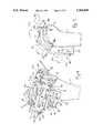
- FIG. 1is an elevational view illustrating the alignment guide of the invention inserted into the intramedullary canal of a distal end of the femur.
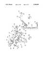
- FIG. 2is a perspective view of the alignment guide of FIG. 1 with the Anterior-Posterior (AP) placement guide connected thereto.
- the brackets of femoral basesare removably connected to the AP placement guide and are illustrated removably secured to the femur by a plurality of screws.
- FIG. 3illustrates the femoral bases connected to the femur by screws.
- the alignment guide and AP placement guidehave been removed.
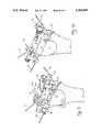
- FIG. 4is a perspective view of the femoral milling guide attached to the femoral bases on the distal end of the femur.
- FIG. 5is an elevational view of FIG. 4 with a milling device (partially shown) illustrated in broken lines to illustrate the relative position of the milling device, milling guide and distal femur.
- FIG. 6is a partial cross-sectional view of the alignment guide of the invention.
- FIG. 7is an exploded view of the alignment guide of the invention.
- FIG. 8is a perspective view of the AP placement guide shown in isolation and partially exploded.
- FIG. 9is a sectional view taken along line 9--9 of FIG. 8.
- FIG. 10is a perspective view of a femoral base shown in isolation and exploded for illustrative purposes.
- FIG. 11is an elevational view of a femoral base of the invention.
- FIG. 12is a cross-sectional view taken along line 12--12 of FIG. 11.
- FIG. 13is an enlarged partial view of a femoral base connected to a femoral milling guide illustrating the cam lock between the base and guide.
- FIG. 14is an enlarged partial view of a femoral base connected to a femoral milling guide illustrating an alternative screw and ramp locking mechanism.
- FIG. 15is an isolated perspective view of the femoral milling guide of the invention.
- FIG. 16is an elevational view taken along line 16--16 of FIG. 15.
- FIG. 17is a side elevational view of the femoral milling guide of FIGS. 15 and 16.
- FIGS. 18 through 20illustrate the use of the milling device of the invention including the use of the plunge cut alignment sheath.
- FIG. 21illustrates the milling of the distal femur using the milling guide and device of this invention with the debris shield in place over the milling device.
- FIG. 22illustrates a partial perspective view of the milling device illustrating the bobbin-shaped end of the milling housing.
- FIG. 23is a perspective view of a notch milling guide which is connectable to the resected femur and guides a milling device for forming a notch in the distal femur.
- the notchis called for when the implant to be fitted to the femur includes mechanisms intended to restrain motion of the knee such as in a constrained condylar implant.
- FIG. 24is the perspective view of FIG. 23 with the notch milling guide connected to the femoral bases.
- FIG. 25is a side elevational view illustrating the notch milling guide of FIG. 24 connected to a resected distal end of a femur by the femoral bases.
- FIG. 26is a perspective view of the notch milling guide of FIG. 23 shown from the posterior side.
- FIG. 27is a side view taken from line 27--27 of FIG. 23.
- FIG. 28is an elevational top view of the notch milling guide of FIG. 24.
- FIG. 29is a perspective view of a remilling guide.
- FIG. 30is a side elevational view of the guide of FIG. 29 in contact with the resected distal femur.
- FIG. 31is a perspective view of the remilling guide in use with the AP placement guide and femoral bases.
- FIG. 32is a perspective view of the femoral bases connected to the resected femur after alignment by the remilling guide as in FIG. 31.
- FIG. 33is a perspective view of a one piece cutting guide connected to the femoral bases of the invention.
- FIG. 34is a side elevational view of FIG. 32.
- FIG. 35is a perspective view of the one piece cutting guide.
- FIG. 36is a elevational view of the one piece cutting guide.
- FIG. 37is a side elevational view of the one piece cutting guide.
- the surgeonforms an intramedullary hole into the center of the distal femur in a known manner to accommodate an intramedullary device.
- the femoral intramedullary alignment guide 10is inserted into the intramedullary hole until the platform 12 of the alignment guide 10 contacts the distal condyles 3, 4 as shown.
- the platform 12may be angled relative to the intramedullary rod 14 to allow the surgeon to align the platform 12 perpendicular to the mechanical axis of the femur 1. The method of angulating the rod relative to the platform is explained below.
- An Anterior-Posterior alignment guide 30(hereafter AP guide 30) having femoral bases 50 temporarily attached thereto is slid onto alignment guide 10.
- AP guide 30includes an arm 32 which is shiftable in the medial-lateral direction of the femur. Arm 32 terminates in a posteriorly extending projection 34. The surgeon adjusts arm 32 such that projection 34 is in contact with the highest anterior point of the anterior femoral condyle.
- the AP guide 30is shiftable in an anterior-posterior direction relative to alignment guide 10 and the femur for proper positioning of arm 32 as explained above.
- a plurality of tapered bone screws 70are inserted through openings 54 in femoral bases 50 as illustrated to secure the bases to the medial and lateral sides of the femur.
- the AP guide 30 and alignment guide 10may be removed by disengaging locking mechanisms 52 thereby freeing the AP guide.
- Alignment guide 10 and AP guide 30are removed leaving only bases 50 connected to femur 1 as illustrated in FIG. 3.
- the specific design and operation of the locking mechanisms 52 of femoral bases 50is described later in the specification with reference being had to FIGS. 10 through 14.
- FIGS. 4 and 5illustrate the milling guide 80 in its environment connected to femoral bases 50 and the femur 1.
- FIGS. 15 through 17illustrate the milling guide alone so that its design might be more clearly understood.
- Milling guide 80is shaped so as to form a plurality of generally flat walls lying in a like plurality of planes which are identified relative to the femoral surfaces to be milled.
- Guide 80includes a femoral anterior wall 82, an anterior chamfered wall 84, a distal wall 86 and a posterior chamfered wall 88 each having upper and lower surfaces as illustrated in FIGS. 4, 5 and 15-17.
- Anterior wall 82includes a pair of generally parallel slots 90 configured as shown for accommodating and guiding a milling device along the anterior surface of the femur for milling the anterior femoral condyle 4 of femur 1.
- An arcuate opening 92is formed in one slot 90, as illustrated, which places slots 90 in communication with one another as illustrated.
- a pair of through bores 94are formed on opposite sides of arcuate opening 92.
- Anterior chamfer wall 84includes a slot 96 having facing arcuate interruptions 98 formed in the side walls of the slot 96 as illustrated.
- Slot 96is formed to accommodate and guide a milling device along the femur 1 to form an anterior chamfer surface 6 on the femur (see FIG. 5).
- a throughbore 100is formed adjacent each arcuate interruption 98.
- Distal wall 86includes a slot 102 having facing arcuate interruptions 104 formed in the side walls of the slot 102.
- Slot 102is formed to accommodate and guide a milling device along the femur to form a prepared distal surface 8 on the femur (see FIG. 5).
- a throughboreis formed adjacent each arcuate interruption 104.
- Posterior chamfer wall 88includes a slot 108 having an arcuate projection 110 formed in the anterior most side wall of the slot as illustrated best in FIG. 16.
- a generally L-shaped support 112is rotatably connected to the posterior surface of the anterior femoral wall 82 by a screw 114 passing through the foot of the support.
- the leg of the supportextends away from the anterior femoral wall 82 and is configured to contact the anterior cortex of femur 1 just proximal to the anterior condyles 4.
- a slot 116is cut into the foot of the support to create a spring out of the foot. In use, the surgeon rotates the support about screw 114 until the distal tip of the leg contacts the highest point on the anterior cortex of the femur adjacent the anterior condyles.
- a tab 118extends from the medial and lateral sides of the anterior chamfer wall 84 in a plane therewith and includes an ovoid opening 120. Similarly, a tab 118 extends from the medial and lateral edges of the distal surface 86 in a plane therewith and includes an ovoid opening 120 therethrough.
- An opening 122is formed adjacent the medial and lateral edges of femoral milling guide 80 between the anterior chamfer wall 84 and the distal wall 86.
- the outermost side walls 123 of openings 122are inclined inwardly and angled posteriorly so as to form a ramp-like structure for engagement by the locking mechanism 52 of femoral base 50 as explained below.
- FIG. 5is provided to illustrate the relative position of the femoral base 50 and the milling guide 80 in relationship to the exposed femur 1.
- a milling deviceis shown in broken lines positioned at each wall 82, 84, 86, and 88 for illustrative purposes. In use, a burr would extend down to the bone for shaping bone as explained below.
- the milling device as guided by the milling guide 80 of the inventionwould allow the surgeon to resect, by milling, the anterior femoral condylar surface 4, the anterior chamfer surface 6, the distal surface 8 and the posterior chamfer surface 9 in a series of milling steps without changing or attaching additional instruments to the femur 1.
- the milling guide 80provides for the milling of the four mentioned surfaces without additional set up or guides from a single reference established by the femoral bases 50.
- Alignment guide 10is illustrated in more detail in FIGS. 6 and 7.
- alignment guide 10includes a hollow housing 18 which is generally cylindrical in shape and is open at one end 20.
- Housing 18further includes a base 22 extending laterally from the generally cylindrical portion of the housing.
- An elongated opening 24is formed through the housing as illustrated along the longitudinal dimension of the housing.
- a throughbore 26is formed through base 22 in communication with opening 24 and transverse thereto.
- External helical threadsare formed on the housing 18 adjacent its open end 20.
- Platform 12includes a pair of legs 13 extending therefrom as illustrated and is secured to base 22 by screws.
- Platform 12further includes a spacer 11 which may be selectively attached to the platform by screws.
- Platform 12 and spacer 11include central openings for accommodating the intramedullary rod 14 therethrough.
- Legs 13define an opening between the platform 12 and the base 22 for accommodating portions of the AP alignment guide 30.
- a generally cylindrical cam 15is provided and is accommodated within housing 18 in a close fit thereto.
- Cam 15is longitudinally slidable within housing 18.
- An elongated openingis formed through cam 15 for alignment with opening 24 of housing 18 when the cam is positioned within housing 18.
- Each longitudinal end of cam 15is bored out with end 17 including internal helical threads.
- a coupler 19having a longitudinal shaft with a threaded end 21 and an annular collar 23 is provided. Threaded end 21 is accommodated by the threaded end 17 of cam 15 and is rotatable therewithin.
- Collar 23is received within a counter bore formed in end 20 of housing 18 as illustrated in FIG. 6.
- An end cap 27having a central opening is threaded onto end 20 of housing 18 and captures collar 23 against longitudinal movement relative to housing 18.
- Knob 16is press fitted onto the non-threaded end of coupler 19 such that as knob 16 is rotated relative to the housing, coupler 19 rotates relative to cam 15.
- a detent 28is accommodated within a threaded through bore within knob 16 and includes a spring-loaded nib to engage the end face of end cap 27.
- a plurality of groovesmay be formed in the end face of end cap 27 for successive engagement with the nib to provide a positive snap feel to the knob as well as to indicate the relative position of the knob.
- An intramedullary rod 14is provided and includes a proximal end 130 and a distal end 132.
- the proximal endincludes an annular recess for accommodating a griping device for the removal of the alignment guide 10 from the intramedullary canal of the femur.
- a transverse through bore 134is formed through rod 14.
- rod 14is pivotally secured within the opening 24 and the aligned opening of cam 15 by a pin 136.
- a portion of the proximal end 134 of the rod 14is flattened and defines caming surfaces 138.
- the surgeonvaries the angle between intramedullary rod 14 and platform 12 so that platform 12 is perpendicular to the mechanical axis of the femur by rotating knob 16 relative to housing 18.
- the rotation of knob 16causes coupler 19 to rotate within cam 15.
- Cam 15is rotationally fixed relative to housing 18 and coupler 19 is longitudinally fixed relative to housing 18. Therefore, when knob 16 rotates coupler 19, the threaded engagement between coupler 19 and cam 15 causes the cam to longitudinally shift within housing 18.
- the longitudinal movement of cam 15causes a cam surface 140 of cam 15 to press against a cam surface 138 on rod 14 thereby causing rod 14 to rotate about pin 136 thereby angulating rod 14 relative to platform 12.
- Indiciamay be provided on knob 16 to indicate to the surgeon the relative angle between the rod and platform.
- AP alignment guide 30, shown isolated in FIGS. 8 and 9,includes a body 31 having a plurality of fingers 39 extending therefrom. The innermost pair of fingers are adapted for accommodation within the spaces created by legs 13 of alignment guide 10 (see FIGS. 2 and 6).
- An inverted T-shaped channel 38extends in a medial-lateral direction adjacent an anterior edge of the AP alignment guide as illustrated.
- An inverted T-shaped blockis slidably accommodated within channel 38 and includes an arm 32 adapted to extend in the direction of the proximal end of the femur (see FIG. 2).
- a posteriorly extending projection 34extends from arm 32.
- a tab 40extends transversely from the distal end of each of the outermost fingers 39 and includes an ovoid opening 42.
- a tab 40extends from the medial and lateral edges adjacent the anterior edge of body 31 and includes an ovoid opening 42 as illustrated.
- Each tab 40includes a channel 46 for accommodation of the femoral bases 50 therein.
- a set screw 44 having an enlarged headis accommodated within a threaded bore in block 38 Screw 44 may be rotated into engagement with the bottom wall of T-channel 36 to temporarily fix the block from movement within the channel.
- An opening 47is formed adjacent the medial and lateral edges of alignment guide 30 between the body 31 and finger 39. The outermost side walls 48 of openings 47 are inclined inwardly and angled posteriorly so as to form a ramp-like structure for engagement by the locking mechanism 52 of femoral base 50.
- Femoral base 50 of the inventionis illustrated in FIGS. 2-5 and 10-13 with an alternative embodiment illustrated in FIG. 14.
- Femoral base 50includes a body 56 defining a substantially flat anterior distal surface 58 and a substantially flat posterior distal surface 60.
- the body 56is curved slightly such that the surfaces 58 and 60 are not in the same plane.
- Locking mechanism 52is situated between surfaces 58 and 60 and includes a bore extending transversely through the body, a cam bar 53 extending through the bore and a handle 51 connected to an end of bar 53 which extends laterally from the body.
- the medial end of the cam bar 53includes a small cam 55 extending transversely to the cam bar. A portion of cam bar 53 is removed to form a relief 57 adjacent the cam 55.
- An ovoid protuberance 62extends in a distal direction from posterior distal surface 60 and a semi-circular protuberance 63 extends in a distal direction from the anterior distal surface 58 as illustrated in the drawings.
- femoral base 50includes a plurality of openings 54. Three openings 54 are positioned anteriorly and three are positioned posteriorly on the body 56. As illustrated best in FIGS. 11 and 12, the anterior openings 54 are angled such that a screw passing therethrough is directed proximally and posteriorly within the bone.
- the posterior openings 54are angled such that a screw passing therethrough is directed proximally and anteriorly within the bone. Therefore, if screws are inserted through at least one anterior opening and at least one posterior opening on the body 56, the screws converge toward each other to thereby securely lock the femoral base 50 to the bone.
- the diameter of the shaft of the screw passing through the body openingshould closely match diameter of the openings 54 to assist in the mechanical interlock being formed.
- mechanism 53includes a relief 57 and a cam 52 formed in cam bar 53 which is rotatable relative to body 56. Connecting and disconnecting the base 50 with locking mechanism 52 is accomplished in the same manner whether the base is being connected to AP alignment guide 30 or milling guide 80 and will therefore only be described in relation to AP guide 30.
- the protuberances 62, 63are aligned and seated within ovoid openings 42 of a pair of tabs 40.
- cam bar 53is slid in a direction away from the AP guide 30.
- cam bar 53is rotated using handle 51 until the relief 57 is facing the AP guide 30.
- Bar 54is slid toward the AP guide 30 until the cam 55 is in general alignment with opening 47 of the AP guide.
- the bar 53is then rotated such that cam 55 enters opening 47 and contacts the inclined wall 48.
- Continued rotationcauses cam 55 to press against the inclined wall 48 to thereby clamp the base 50 to the AP guide 30.
- the cam bar 53is rotated such that the cam 55 moves away from the inclined wall 48.
- locking mechanism 52'includes a screw 64 threadably accommodated by base 50 and including at one end a smooth conical tip 65 and a knob 66 at the other end.
- the guide 30'includes an opening 47' which includes an inclined wall 48'. In use, to lock the guide 30' to base 50', screw 64 is rotated until its conical tip 65 contacts the inclined wall 48' to clamp guide 30' between the tip 65 and base 50'.
- a milling device 150 for use with the femoral milling guide 80is illustrated in FIGS. 18 through 20 in association with a portion of guide 80.
- Milling device 150includes a driver, a generally cylindrical housing 154 and being connected to an external energy source (not shown) by cord 156.
- the external energy sourcecould be pressurized gas or an electrical power source.
- the end of the housingterminates in a bobbin-shaped nose portion 158 as illustrated more clearly in FIG. 22.
- the bobbin shape of the nose portion 158defines a predetermined spacing 160 between plate 162 and the end 164 of the housing which are interconnected by a tubular shaft 166.
- a burr 168 having a shaft 170is attached to the milling device 150 using a known chuck to securely clamp the burr to the device 150. Milling device 150 rotates burr 168 in use. Burr 168 may also be referred to as an end cutter and has a end face which is substantially perpendicular to the burr shaft.
- a sleeve 172is carried by housing 154 and is slidable longitudinally along the housing between an extended position as illustrated in FIG. 18 and a retracted position as illustrated in FIG. 20.
- Sleeve 172is generally cylindrical and shaped to frictionally engage the outer surface of the housing 154.
- An annular rib 174is formed adjacent one end for seating within an annular groove 152 on housing 154 as illustrated in FIG. 18.
- Rib 174 and groove 152combine to form a detent to frictionally retain the sleeve in the extended position of FIG. 18.
- the end adjacent the rib 174yields slightly as illustrated; therefore, one or more slots may be formed in the sleeve to prevent its breaking when in a retracted position.
- a pair of shoulders 176extend outwardly from the cylindrical portion of sleeve 172 adjacent one end and each includes a protrusion 178 extending parallel to the longitudinal axis of the sleeve.
- sleeve 172serves two functions. Foremost is safety. Before the milling device is seated on guide 80, the surgeon and other operating room personnel are protected from the sharp edges of the burr by sleeve 172 in its extended position. The sleeve 172 also serves to align the milling device 150 and burr 168 for a plunge cut into the bone's surface. As mentioned earlier in the description of milling guide 80, the slots 90, 96, 102, and 108 of the guide each include arcuate portions 92, 98, 104, and 112 respectively. These arcuate portions or interruptions in the slots permit the milling device and burr to be inserted perpendicular to their respective walls.
- Sleeve 172provides proper alignment between the arcuate sections and the burr so that as the burr rotates around its shaft and is lowered into milling engagement with the bone, the burr does not contact the guide. This alignment is accomplished by positioning protrusions 178 in the various through bores formed adjacent the arcuate portions of the slots. For example, referring to FIG. 18, protrusions 178 are positioned within through bores 100 so that the burr 168 is aligned with arcuate interruptions 98 of slot 96. Once properly aligned, the surgeon activates milling device 150 to rotate burr 168 and then gently pushes the milling device in the direction of arrow 151.
- the surgeonmay guide the milling device along the slot for milling the entire surface of the bone.
- the bobbin shaped nose portion 158 of the milling deviceengages the slots to ensure that the milling device and burr are maintained substantially perpendicular to the particular wall of the milling guide 80. Maintaining the perpendicular relationship is vital to provide a very flat milled surface to accommodate the implant.
- a perspective view of the nose portion 158 of the milling deviceis illustrated in FIG. 22 in isolation.
- FIG. 21illustrates a protective sheet 180 which may be used during surgery to contain the particulate debris formed by milling the bone to the surgical site.
- Sheet 180is translucent so that the surgeon's view of the milling process is not interrupted.
- the sheetmay have an external periphery of a number of shapes and includes a central opening to accommodate the cord 156 of milling device 150.
- the sheet 180is very limp and conforms easily to its surroundings to entrap as much of the bone debris as possible.
- the surgeon's handsare positioned under sheet 18 and are grasping the milling device 150. Therefore, the sheet 180 provides a barrier to prevent debris from escaping the surgical site but does not create an impediment to the surgeon during the surgical procedure.
- the sheet 180is positioned on the milling device 150 before the removable cord 156 is connected to the housing 154.
- the surgeonmay be required to form a notch in the distal end of the resected bone.
- thisis required to accommodate implants referred to as constrained condylar knees and posterior stabilized knees.
- implants referred to as constrained condylar knees and posterior stabilized kneesIn these instances, generally the posterior and/or anterior cruciate ligaments of the knee are not functioning properly or have been removed as determined by the surgeon.
- the implantis therefore required to replace the functions of the ligaments.
- the femoral implantit is common for the femoral implant to include some type of protrusion which extends upwardly from the tibial plate and into the femur. To accommodate such an implant, a notch must be formed in the distal femur.
- Notch milling guide 180illustrated in FIGS. 23-28, is provided with the instrument set of the invention and includes sides 182, 184 which are shaped to conform with the upper surfaces of bases 50 and have openings 186 for accommodating protuberances 62, 63 of the bases.
- a bar 188extends between the anterior most ends of sides 182, 184 and a bar 190 extends between the posterior most ends of sides 182, 184 to maintain the sides in a spaced relationship as illustrated.
- a guide body 192is carried by bars 188, 190 and is shiftable on the bars between sides 182, 184.
- Guide body 192includes a pair of tabs 194 which extend in opposition to each other.
- Tabs 194are provided for engagement with conical tips 65 of screw 64 as carried by the femoral base 50 illustrated in FIGS. 14 and 24.
- Body 192further includes a closed end slot 196 extending posteriorly. Slot 196 is configured to accommodate the bobbin shaped nose portion 158 of the milling device 150 in a similar manner as is illustrated in FIGS. 18-29.
- a series of slots 198are formed adjacent the posterior edge of body 192 and adjacent bar 190 as illustrated in FIG. 26. Slots 198 are configured to accommodate an oscillating saw blade (not shown) for the resection of the posterior condyles 9 (see FIG. 25).
- the surgeonplaces notch milling guide 180 on bases 50 and slides the guide body 192 medially and laterally on bars 188, 190 until an equal amount of the femur can be seen on each side of guide body 192 (see FIG. 28).
- Thisallows the surgeon to place the notch in the desired location relative to anatomical landmarks.
- Screws 64are then turned until the conical tip 65 of each screw contacts a tab 194. The screws are then tightened against the tabs.
- Each screw 64places a lateral force on a tab 194 in the direction of the other screw 64. Therefore, with each screw 64 tightened, guide body 192 is secured against a medial-lateral movement along bars 188, 190.
- the surgeonmills a notch in the distal end of the femur by using the milling device of FIGS. 18-20 in a similar manner as described earlier.
- the bobbin shaped nose portion 158 of milling device 150is accommodated by slot 196 to guide burr 168 in an anterior-posterior direction. With burr 168 rotating, a slot (not shown) is formed in the distal end of the resected femur.
- the surgeonresects the posterior condyles 3 with the use of a known oscillating saw and blade (not shown).
- the bladeis accommodated within an aligned pair of laterally aligned slots 198.
- multiple pairs of laterally aligned slots 198are provided to allow the surgeon to choose how much of the posterior condyles should be removed.
- the milling of the distal femuris now complete and the femoral bases 50 may be removed by removing tapered bone screws 70.
- the surgeon at this pointwill use a provisional implant to check the fit of the milled bone with the implant and the knee joint is evaluated for a proper anatomical set up as determined by the surgeon. The surgeon may determine that in order to receive an optimum result, additional bone should milled from the femur. Such remilling requires the milling instruments to be aligned relative to the existing milled surfaces.
- remilling alignment guide 200 of FIGS. 29-31is implemented in the following manner to reattach the femoral bases 50 in alignment with the femur relative to the previously milled surfaces 6 and 8.
- remilling alignment guide 200includes a base 202 having an inclined anterior wall 204 which forms an obtuse corner 206 at its junction with base 202.
- corner 206closely matches the angle formed by anterior chamfer surface 6 and distal surface 8 formed by the initially milling procedures as described above. This provides a precise alignment between the femur and the alignment guide 200.
- a projection 208extends from inclined anterior wall 204 as illustrated.
- a housing 210extends integrally from base 202 and includes a rectangular slot 212 and a plurality of through bores 214 as illustrated best in FIG. 29.
- Through bores 214extend through base 202 and are provided to accommodate fastening devices such as screws or pins (not shown).
- the distance between wall 213 of slot 212 and the bone contacting surface 203 of base 202is a predetermined distance "h" (see FIG. 20) and defines the amount of additional bone stock to be removed during the remilling procedure. As will be seen by decreasing the distance h, for example, by making base 202 thinner, the amount of bone to be removed is increased. Conversely, by increasing the thickness of the base 202 and thereby distance h, the amount of bone stock to be removed will be reduced.
- Alignment guide 200is centered on the femur so that an equal amount to the femur is visible on the medial and lateral sides of the guide.
- Guide 200may be secured in place by two or more pins or screws (not shown) accommodated by through bores 214.
- AP alignment guide 30is slid on to remilling guide 200 with fingers 39 accommodated within the rectangular slot 212 of the remilling guide. With the AP alignment guide fully seated on the remilling guide (as illustrated in FIG. 31), the surgeon inserts a plurality tapered bone screw 70 to secure femoral bases 50 to the femur in the manner described previously.
- the locking mechanisms 52are disengaged to release the AP alignment guide and remilling guide which are then removed leaving only femoral bases 50 connected to the milled femur as illustrated in FIG. 32. From this point on, remilling of the femur is accomplished in exactly the same manner as described earlier using femoral milling guide 80 and notch milling guide 180 previously described. Since the reference points for these milling guides are bases 50, which were reconnected with reference to the milled surfaces by remilling guide 200, the amount of bone removed during remilling is determined by the remilling guide as mentioned earlier.
- the instrument set of this inventionprovides the surgeon the option of connecting a cutting guide to the femoral bases to resect the bone using a standard cutting device such as an oscillating powered surgical saw (not shown).
- the five in one cutting guide 220 of the instrument set of the inventionis illustrated in FIGS. 33 through 37 and includes a body 222 including a slight bend therein as shown.
- a pair of tabs 224extend from the medial and lateral edges of body 222 and include openings therein for accommodating the protrusions 62, 63 from femoral bases 50.
- a recessis formed in the medial and lateral sides of the body 22 for accommodating the conical tip 65 of the alternative locking mechanism 52' for base 50.
- a slot 226is formed in body 222 inclined so as to guide a saw blade along the path illustrated by broken line 227 for resection of the distal surface of the femur.
- Slot 228is formed in body 222 inclined so as to guide a saw blade along the path illustrated by broken line 229 for resection of the anterior condyle.
- a slot 230is formed in body 222 inclined so as to guide a saw blade along the path illustrated by broken line 231 for forming a posterior chamfered surface.
- a slot 232is formed in body 222 inclined so as to guide a saw blade along the path illustrated by broken line 233 for forming an anterior chamfered surface.
- a pair of aligned slots 234are provided in base 222 for guiding a saw blade along the path illustrated by broken line 235 for the resection of the posterior condyles.
- the surgeonestablishes the femoral bases 50 in the same manner as described above with reference to the milling guides of the invention. However, instead of connecting the femoral milling guide 80 to the bases, the surgeon attaches the five in one cutting guide 220 to the bases. With the cutting guide connected to the bases, the surgeon inserts a blade through each slot to make all the cuts necessary for placement of a prosthetic knee without ever moving, shifting or otherwise reorienting or changing the five in one cutting guide. By making all the cuts necessary without changing guides, the relative precision between the cuts made can be more precisely controlled thus leading to a better fitting implant.
- the remilling guide 200 and AP alignment guide 30is used to reestablish the femoral bases 50 in the same manner as described above.
- the cutting guide 220is then reattached to the bases and the femur is re-cut.
Landscapes
- Health & Medical Sciences (AREA)
- Surgery (AREA)
- Life Sciences & Earth Sciences (AREA)
- Biomedical Technology (AREA)
- Public Health (AREA)
- Oral & Maxillofacial Surgery (AREA)
- Nuclear Medicine, Radiotherapy & Molecular Imaging (AREA)
- Veterinary Medicine (AREA)
- Dentistry (AREA)
- Engineering & Computer Science (AREA)
- Orthopedic Medicine & Surgery (AREA)
- Heart & Thoracic Surgery (AREA)
- Medical Informatics (AREA)
- Molecular Biology (AREA)
- Animal Behavior & Ethology (AREA)
- General Health & Medical Sciences (AREA)
- Physical Education & Sports Medicine (AREA)
- Transplantation (AREA)
- Surgical Instruments (AREA)
- Prostheses (AREA)
Abstract
Description
This application is a continuation of application Ser. No. 08/435,103 filed May 4, 1995, now abandoned, which is a Division of Ser. No. 08/169,459 filed Dec. 17, 1993, now U.S. Pat. No. 5,474,559 which is a Continuation-in-Part of Ser. No. 08/087,933, filed Jul. 6, 1993, abandoned.
This invention relates to instruments used in the preparation of the femur during a total knee arthroplasty and has specific relevance to instrumentation providing for the milling of the femur while providing the option of resecting portions of the femur using a one piece cutting guide.
In an orthopaedic surgery to replace part or all of a patient's joint with a prosthetic implant, a portion of the implant receiving bone is prepared to closely match the mating surfaces of the implant. If the knee joint is being replaced, the distal end of the femur is prepared to accommodate a femoral knee component and the proximal end of the tibia is prepared to accommodate a tibial component.
Heretofore, these surfaces were substantially prepared by the use of reciprocating or oscillating saw blades used in conjunction with a series of saw guides. The guides may comprise merely a platform on which the surgeon rests the blade during resection or may comprise a slot for capturing the saw blade therewithin. Typically, in the preparation of the femur, a series of cutting guides are placed adjacent the distal femur in a specific order to resect portions of the femur in succession. These cutting guides are generally individually aligned by the surgeon with reference to specific anatomic landmarks. The use of multiple cutting guides requiring individual alignment by the surgeon may lead to inaccuracies in the cuts which would provide a less than optimal fit between the bone and implant. Such saw blades commonly used in the resection of bone are illustrated in U.S. Pat. Nos. 5,002,555, 5,133,728, and 5,135,533. An example of a typical cutting guide may be had by reference to U.S. Pat. No. 5,053,037, illustrating a saw guide having captured slots.
The consistency of results achieved when using a saw blade and a series of cutting guides may vary widely from surgeon to surgeon.
The milling instrumentation of this invention solves the deficiencies of the prior art systems by providing a milling guide connected to the femur for accommodating a milling device. The milling instrumentation includes an alignment guide which is used by the surgeon to set a femoral bracket or base on the medial and lateral sides of the exposed femur adjacent its distal end. Once the brackets are set, the alignment guide is removed and a milling guide is connected to the bases. The milling guide establishes a series of reference planes each including a slot. A powered milling device having a burr connected thereto is guided by the slots along the reference planes to accurately mill away a portion of the bone. The distance between the milling device and the distal end of the burr is relatively short, and the shaft of the burr is stiff to thereby eliminate any deflection in the burr. Further, the milling device includes a bobbin-shaped tip which positively engages the slots to ensure that the milling device is held substantially perpendicular to the reference planes of the milling guide. Controlling the milling device in this manner ensures an extremely flat milled surface for accommodating the implant. If necessary, other instrumentation may be connected to the femoral bases which would form a common connection point for the additional instruments thereby ensuring alignment between the various instruments.
Optionally, once the femoral bases are connected to the distal end of the femur, a one piece cutting guide may be connected to the bases to allow resection of the bone by a standard oscillating saw blade. The cutting guide includes a plurality of slots such that all the cuts required for the femur can be made with one cutting guide without reorienting the guide. By making all the cuts required without moving the guide or requiring additional guides, the accuracy and repeatability of the cuts are increased.
Accordingly, it is an advantage of this invention to provide for novel milling instrumentation for preparing a bone surface to accommodate an orthopaedic implant.
Another advantage of the invention is to provide for milling instrumentation which includes an alignment guide for connecting a pair of brackets to an exposed bone.
Another advantage of the invention is to provide for milling instrumentation which includes a milling guide connected to a bone for guiding a milling device to prepare a surface of the bone for accommodating an orthopaedic implant.
Still another advantage of the invention is to provide for a novel milling device having a bobbin-shaped end for captured engagement within the slot of the milling guide.
Yet another advantage of the invention is to provide a base for connection to sides of a bone for connection of a plurality of milling devices.
Still another advantage of the invention is to provide for an instrumentation set for resecting bone that provides for the optional attachment of a cutting guide or a milling guide.
Still another advantage of the invention is to provide for a one piece cutting guide.
Additional advantages may be understood by a reading of the following description taken with the accompanying drawings.
FIG. 1 is an elevational view illustrating the alignment guide of the invention inserted into the intramedullary canal of a distal end of the femur.
FIG. 2 is a perspective view of the alignment guide of FIG. 1 with the Anterior-Posterior (AP) placement guide connected thereto. The brackets of femoral bases are removably connected to the AP placement guide and are illustrated removably secured to the femur by a plurality of screws.
FIG. 3 illustrates the femoral bases connected to the femur by screws. The alignment guide and AP placement guide have been removed.
FIG. 4 is a perspective view of the femoral milling guide attached to the femoral bases on the distal end of the femur.
FIG. 5 is an elevational view of FIG. 4 with a milling device (partially shown) illustrated in broken lines to illustrate the relative position of the milling device, milling guide and distal femur.
FIG. 6 is a partial cross-sectional view of the alignment guide of the invention.
FIG. 7 is an exploded view of the alignment guide of the invention.
FIG. 8 is a perspective view of the AP placement guide shown in isolation and partially exploded.
FIG. 9 is a sectional view taken along line 9--9 of FIG. 8.
FIG. 10 is a perspective view of a femoral base shown in isolation and exploded for illustrative purposes.
FIG. 11 is an elevational view of a femoral base of the invention.
FIG. 12 is a cross-sectional view taken alongline 12--12 of FIG. 11.
FIG. 13 is an enlarged partial view of a femoral base connected to a femoral milling guide illustrating the cam lock between the base and guide.
FIG. 14 is an enlarged partial view of a femoral base connected to a femoral milling guide illustrating an alternative screw and ramp locking mechanism.
FIG. 15 is an isolated perspective view of the femoral milling guide of the invention.
FIG. 16 is an elevational view taken alongline 16--16 of FIG. 15.
FIG. 17 is a side elevational view of the femoral milling guide of FIGS. 15 and 16.
FIGS. 18 through 20 illustrate the use of the milling device of the invention including the use of the plunge cut alignment sheath.
FIG. 21 illustrates the milling of the distal femur using the milling guide and device of this invention with the debris shield in place over the milling device.
FIG. 22 illustrates a partial perspective view of the milling device illustrating the bobbin-shaped end of the milling housing.
FIG. 23 is a perspective view of a notch milling guide which is connectable to the resected femur and guides a milling device for forming a notch in the distal femur. The notch is called for when the implant to be fitted to the femur includes mechanisms intended to restrain motion of the knee such as in a constrained condylar implant.
FIG. 24 is the perspective view of FIG. 23 with the notch milling guide connected to the femoral bases.
FIG. 25 is a side elevational view illustrating the notch milling guide of FIG. 24 connected to a resected distal end of a femur by the femoral bases.
FIG. 26 is a perspective view of the notch milling guide of FIG. 23 shown from the posterior side.
FIG. 27 is a side view taken fromline 27--27 of FIG. 23.
FIG. 28 is an elevational top view of the notch milling guide of FIG. 24.
FIG. 29 is a perspective view of a remilling guide.
FIG. 30 is a side elevational view of the guide of FIG. 29 in contact with the resected distal femur.
FIG. 31 is a perspective view of the remilling guide in use with the AP placement guide and femoral bases.
FIG. 32 is a perspective view of the femoral bases connected to the resected femur after alignment by the remilling guide as in FIG. 31.
FIG. 33 is a perspective view of a one piece cutting guide connected to the femoral bases of the invention.
FIG. 34 is a side elevational view of FIG. 32.
FIG. 35 is a perspective view of the one piece cutting guide.
FIG. 36 is a elevational view of the one piece cutting guide.
FIG. 37 is a side elevational view of the one piece cutting guide.
To illustrate the orientation of the instruments shown in the drawings and herein described, a small compass is illustrated on many drawings demonstrating orientation of the instrument with reference to the relative anatomical axes of the femur as are well understood in orthopaedics.
The preferred embodiments herein described are not intended to be exhaustive or to limit the invention to the precise forms disclosed. Rather, they are chosen and described to best explain the invention so that others skilled in the art might utilize their teachings.
Initially, after thedistal end 2 of thefemur 1 is exposed consistent with standard surgical techniques, the surgeon forms an intramedullary hole into the center of the distal femur in a known manner to accommodate an intramedullary device. The femoralintramedullary alignment guide 10 is inserted into the intramedullary hole until theplatform 12 of thealignment guide 10 contacts thedistal condyles platform 12 may be angled relative to theintramedullary rod 14 to allow the surgeon to align theplatform 12 perpendicular to the mechanical axis of thefemur 1. The method of angulating the rod relative to the platform is explained below.
An Anterior-Posterior alignment guide 30 (hereafter AP guide 30) havingfemoral bases 50 temporarily attached thereto is slid ontoalignment guide 10.AP guide 30 includes anarm 32 which is shiftable in the medial-lateral direction of the femur.Arm 32 terminates in aposteriorly extending projection 34. The surgeon adjustsarm 32 such thatprojection 34 is in contact with the highest anterior point of the anterior femoral condyle. TheAP guide 30 is shiftable in an anterior-posterior direction relative toalignment guide 10 and the femur for proper positioning ofarm 32 as explained above. Once the surgeon is satisfied with position ofAP guide 30, a plurality of tapered bone screws 70 are inserted throughopenings 54 infemoral bases 50 as illustrated to secure the bases to the medial and lateral sides of the femur. Once thebases 50 are secured to the femur, theAP guide 30 and alignment guide 10 may be removed by disengaginglocking mechanisms 52 thereby freeing the AP guide.Alignment guide 10 and AP guide 30 are removed leaving only bases 50 connected tofemur 1 as illustrated in FIG. 3. The specific design and operation of the lockingmechanisms 52 offemoral bases 50 is described later in the specification with reference being had to FIGS. 10 through 14.
After theAP alignment guide 30 and alignment guide 10 are removed, a generally C-shaped femoral milling guide 80 (see FIGS. 4 and 5) is placed ontobases 50 and secured thereto by lockingmechanisms 52. FIGS. 4 and 5 illustrate the millingguide 80 in its environment connected tofemoral bases 50 and thefemur 1. FIGS. 15 through 17 illustrate the milling guide alone so that its design might be more clearly understood. Millingguide 80 is shaped so as to form a plurality of generally flat walls lying in a like plurality of planes which are identified relative to the femoral surfaces to be milled.Guide 80 includes a femoralanterior wall 82, an anterior chamferedwall 84, adistal wall 86 and a posterior chamferedwall 88 each having upper and lower surfaces as illustrated in FIGS. 4, 5 and 15-17.Anterior wall 82 includes a pair of generallyparallel slots 90 configured as shown for accommodating and guiding a milling device along the anterior surface of the femur for milling the anteriorfemoral condyle 4 offemur 1. An arcuate opening 92 is formed in oneslot 90, as illustrated, which placesslots 90 in communication with one another as illustrated. A pair of throughbores 94 are formed on opposite sides of arcuate opening 92.Anterior chamfer wall 84 includes a slot 96 having facingarcuate interruptions 98 formed in the side walls of the slot 96 as illustrated. Slot 96 is formed to accommodate and guide a milling device along thefemur 1 to form an anterior chamfer surface 6 on the femur (see FIG. 5). Athroughbore 100 is formed adjacent eacharcuate interruption 98.Distal wall 86 includes aslot 102 having facingarcuate interruptions 104 formed in the side walls of theslot 102.Slot 102 is formed to accommodate and guide a milling device along the femur to form a prepared distal surface 8 on the femur (see FIG. 5). A throughbore is formed adjacent eacharcuate interruption 104.Posterior chamfer wall 88 includes aslot 108 having anarcuate projection 110 formed in the anterior most side wall of the slot as illustrated best in FIG. 16. A generally L-shapedsupport 112 is rotatably connected to the posterior surface of the anteriorfemoral wall 82 by ascrew 114 passing through the foot of the support. The leg of the support extends away from the anteriorfemoral wall 82 and is configured to contact the anterior cortex offemur 1 just proximal to theanterior condyles 4. Aslot 116 is cut into the foot of the support to create a spring out of the foot. In use, the surgeon rotates the support aboutscrew 114 until the distal tip of the leg contacts the highest point on the anterior cortex of the femur adjacent the anterior condyles. The spring formed from the foot provides sufficient spring effect to allow the support to be placed into position with a degree of force thereby providing additional stability to theanterior condyle wall 82 of millingguide 80. Atab 118 extends from the medial and lateral sides of theanterior chamfer wall 84 in a plane therewith and includes anovoid opening 120. Similarly, atab 118 extends from the medial and lateral edges of thedistal surface 86 in a plane therewith and includes anovoid opening 120 therethrough. Anopening 122 is formed adjacent the medial and lateral edges offemoral milling guide 80 between theanterior chamfer wall 84 and thedistal wall 86. Theoutermost side walls 123 ofopenings 122 are inclined inwardly and angled posteriorly so as to form a ramp-like structure for engagement by thelocking mechanism 52 offemoral base 50 as explained below.
FIG. 5 is provided to illustrate the relative position of thefemoral base 50 and the millingguide 80 in relationship to the exposedfemur 1. A milling device is shown in broken lines positioned at eachwall guide 80 of the invention would allow the surgeon to resect, by milling, the anterior femoralcondylar surface 4, the anterior chamfer surface 6, the distal surface 8 and the posterior chamfer surface 9 in a series of milling steps without changing or attaching additional instruments to thefemur 1. The millingguide 80 provides for the milling of the four mentioned surfaces without additional set up or guides from a single reference established by the femoral bases 50.
A generallycylindrical cam 15 is provided and is accommodated withinhousing 18 in a close fit thereto.Cam 15 is longitudinally slidable withinhousing 18. An elongated opening is formed throughcam 15 for alignment with opening 24 ofhousing 18 when the cam is positioned withinhousing 18. Each longitudinal end ofcam 15 is bored out with end 17 including internal helical threads. A coupler 19 having a longitudinal shaft with a threadedend 21 and anannular collar 23 is provided. Threadedend 21 is accommodated by the threaded end 17 ofcam 15 and is rotatable therewithin.Collar 23 is received within a counter bore formed inend 20 ofhousing 18 as illustrated in FIG. 6. Anend cap 27 having a central opening is threaded ontoend 20 ofhousing 18 and capturescollar 23 against longitudinal movement relative tohousing 18.Knob 16 is press fitted onto the non-threaded end of coupler 19 such that asknob 16 is rotated relative to the housing, coupler 19 rotates relative tocam 15. Adetent 28 is accommodated within a threaded through bore withinknob 16 and includes a spring-loaded nib to engage the end face ofend cap 27. A plurality of grooves (not shown) may be formed in the end face ofend cap 27 for successive engagement with the nib to provide a positive snap feel to the knob as well as to indicate the relative position of the knob.
Anintramedullary rod 14 is provided and includes aproximal end 130 and adistal end 132. The proximal end includes an annular recess for accommodating a griping device for the removal of thealignment guide 10 from the intramedullary canal of the femur. A transverse throughbore 134 is formed throughrod 14. As illustrated,rod 14 is pivotally secured within theopening 24 and the aligned opening ofcam 15 by apin 136. As is further illustrated, a portion of theproximal end 134 of therod 14 is flattened and defines caming surfaces 138.
In use, the surgeon varies the angle betweenintramedullary rod 14 andplatform 12 so thatplatform 12 is perpendicular to the mechanical axis of the femur by rotatingknob 16 relative tohousing 18. The rotation ofknob 16 causes coupler 19 to rotate withincam 15.Cam 15 is rotationally fixed relative tohousing 18 and coupler 19 is longitudinally fixed relative tohousing 18. Therefore, whenknob 16 rotates coupler 19, the threaded engagement between coupler 19 andcam 15 causes the cam to longitudinally shift withinhousing 18. The longitudinal movement ofcam 15 causes acam surface 140 ofcam 15 to press against acam surface 138 onrod 14 thereby causingrod 14 to rotate aboutpin 136 thereby angulatingrod 14 relative toplatform 12. Indicia may be provided onknob 16 to indicate to the surgeon the relative angle between the rod and platform.
Thefemoral base 50 of the invention is illustrated in FIGS. 2-5 and 10-13 with an alternative embodiment illustrated in FIG. 14. In practice, twofemoral bases 50 are required; however, only one need be described here as the two bases in use are simply mirror images of one another.Femoral base 50 includes a body 56 defining a substantially flat anteriordistal surface 58 and a substantially flat posteriordistal surface 60. The body 56 is curved slightly such that thesurfaces mechanism 52 is situated betweensurfaces cam bar 53 extending through the bore and ahandle 51 connected to an end ofbar 53 which extends laterally from the body. The medial end of thecam bar 53 includes asmall cam 55 extending transversely to the cam bar. A portion ofcam bar 53 is removed to form arelief 57 adjacent thecam 55. Anovoid protuberance 62 extends in a distal direction from posteriordistal surface 60 and asemi-circular protuberance 63 extends in a distal direction from the anteriordistal surface 58 as illustrated in the drawings. As mentioned earlier and as illustrated in the drawings,femoral base 50 includes a plurality ofopenings 54. Threeopenings 54 are positioned anteriorly and three are positioned posteriorly on the body 56. As illustrated best in FIGS. 11 and 12, theanterior openings 54 are angled such that a screw passing therethrough is directed proximally and posteriorly within the bone. Theposterior openings 54 are angled such that a screw passing therethrough is directed proximally and anteriorly within the bone. Therefore, if screws are inserted through at least one anterior opening and at least one posterior opening on the body 56, the screws converge toward each other to thereby securely lock thefemoral base 50 to the bone. Preferably, the diameter of the shaft of the screw passing through the body opening should closely match diameter of theopenings 54 to assist in the mechanical interlock being formed.
The operation of thelocking mechanism 52 is illustrated in FIG. 13. As mentioned,mechanism 53 includes arelief 57 and acam 52 formed incam bar 53 which is rotatable relative to body 56. Connecting and disconnecting the base 50 withlocking mechanism 52 is accomplished in the same manner whether the base is being connected toAP alignment guide 30 or millingguide 80 and will therefore only be described in relation toAP guide 30. To connect a base 50 toAP guide 30, theprotuberances ovoid openings 42 of a pair oftabs 40. To permit the base 50 to fully seat against thetabs 40,cam bar 53 is slid in a direction away from theAP guide 30. To lock the base to the guide,cam bar 53 is rotated usinghandle 51 until therelief 57 is facing theAP guide 30.Bar 54 is slid toward theAP guide 30 until thecam 55 is in general alignment with opening 47 of the AP guide. Thebar 53 is then rotated such thatcam 55 entersopening 47 and contacts theinclined wall 48. Continued rotation causescam 55 to press against theinclined wall 48 to thereby clamp the base 50 to theAP guide 30. To disengage base 50 from the guide, thecam bar 53 is rotated such that thecam 55 moves away from theinclined wall 48.
An alternative embodiment of the locking mechanism is illustrated in FIG. 14. In the alternative embodiment, locking mechanism 52' includes ascrew 64 threadably accommodated bybase 50 and including at one end a smoothconical tip 65 and aknob 66 at the other end. The guide 30' includes an opening 47' which includes an inclined wall 48'. In use, to lock the guide 30' to base 50', screw 64 is rotated until itsconical tip 65 contacts the inclined wall 48' to clamp guide 30' between thetip 65 and base 50'.
Amilling device 150 for use with thefemoral milling guide 80 is illustrated in FIGS. 18 through 20 in association with a portion ofguide 80.Milling device 150 includes a driver, a generallycylindrical housing 154 and being connected to an external energy source (not shown) bycord 156. As is well known in the industry, the external energy source could be pressurized gas or an electrical power source. The end of the housing terminates in a bobbin-shapednose portion 158 as illustrated more clearly in FIG. 22. The bobbin shape of thenose portion 158 defines apredetermined spacing 160 betweenplate 162 and theend 164 of the housing which are interconnected by atubular shaft 166. Aburr 168 having ashaft 170 is attached to themilling device 150 using a known chuck to securely clamp the burr to thedevice 150.Milling device 150 rotatesburr 168 in use.Burr 168 may also be referred to as an end cutter and has a end face which is substantially perpendicular to the burr shaft. Asleeve 172 is carried byhousing 154 and is slidable longitudinally along the housing between an extended position as illustrated in FIG. 18 and a retracted position as illustrated in FIG. 20.Sleeve 172 is generally cylindrical and shaped to frictionally engage the outer surface of thehousing 154. Anannular rib 174 is formed adjacent one end for seating within anannular groove 152 onhousing 154 as illustrated in FIG. 18.Rib 174 and groove 152 combine to form a detent to frictionally retain the sleeve in the extended position of FIG. 18. When the sleeve is retracted, the end adjacent therib 174 yields slightly as illustrated; therefore, one or more slots may be formed in the sleeve to prevent its breaking when in a retracted position. A pair ofshoulders 176 extend outwardly from the cylindrical portion ofsleeve 172 adjacent one end and each includes aprotrusion 178 extending parallel to the longitudinal axis of the sleeve.
In use,sleeve 172 serves two functions. Foremost is safety. Before the milling device is seated onguide 80, the surgeon and other operating room personnel are protected from the sharp edges of the burr bysleeve 172 in its extended position. Thesleeve 172 also serves to align themilling device 150 andburr 168 for a plunge cut into the bone's surface. As mentioned earlier in the description of millingguide 80, theslots arcuate portions Sleeve 172 provides proper alignment between the arcuate sections and the burr so that as the burr rotates around its shaft and is lowered into milling engagement with the bone, the burr does not contact the guide. This alignment is accomplished by positioningprotrusions 178 in the various through bores formed adjacent the arcuate portions of the slots. For example, referring to FIG. 18,protrusions 178 are positioned within throughbores 100 so that theburr 168 is aligned witharcuate interruptions 98 of slot 96. Once properly aligned, the surgeon activates millingdevice 150 to rotateburr 168 and then gently pushes the milling device in the direction of arrow 151. Pushing themilling device 150 in the direction of arrow 151 unseatsrib 174 fromgroove 152 thus allowing the burr be lowered into milling engagement with the bone as shown in FIG. 19. Also of importance at this point, it should be noted that thenose portion 158 of the milling device is aligned with theguide 80 such that the walls forming the slot are captured betweenplate 162 and end 164. To permit the milling device and burr to be guided by the surgeon over the entire length of the slot, thesleeve 172 is pulled in the direction ofarrows 153 by the surgeon to disengage the protrusions from the through bores as illustrated in FIG. 20. With the sleeve in the retracted position of FIG. 20, the surgeon may guide the milling device along the slot for milling the entire surface of the bone. As mentioned, the bobbin shapednose portion 158 of the milling device engages the slots to ensure that the milling device and burr are maintained substantially perpendicular to the particular wall of the millingguide 80. Maintaining the perpendicular relationship is vital to provide a very flat milled surface to accommodate the implant. A perspective view of thenose portion 158 of the milling device is illustrated in FIG. 22 in isolation.
FIG. 21 illustrates aprotective sheet 180 which may be used during surgery to contain the particulate debris formed by milling the bone to the surgical site.Sheet 180 is translucent so that the surgeon's view of the milling process is not interrupted. The sheet may have an external periphery of a number of shapes and includes a central opening to accommodate thecord 156 ofmilling device 150. Preferably, thesheet 180 is very limp and conforms easily to its surroundings to entrap as much of the bone debris as possible. In use, the surgeon's hands are positioned undersheet 18 and are grasping themilling device 150. Therefore, thesheet 180 provides a barrier to prevent debris from escaping the surgical site but does not create an impediment to the surgeon during the surgical procedure. Thesheet 180 is positioned on themilling device 150 before theremovable cord 156 is connected to thehousing 154.
Depending on the type of femoral implant to be accommodated by the femur, the surgeon may be required to form a notch in the distal end of the resected bone. Typically this is required to accommodate implants referred to as constrained condylar knees and posterior stabilized knees. In these instances, generally the posterior and/or anterior cruciate ligaments of the knee are not functioning properly or have been removed as determined by the surgeon. The implant is therefore required to replace the functions of the ligaments. To do so, it is common for the femoral implant to include some type of protrusion which extends upwardly from the tibial plate and into the femur. To accommodate such an implant, a notch must be formed in the distal femur.
Notch millingguide 180, illustrated in FIGS. 23-28, is provided with the instrument set of the invention and includessides bases 50 and haveopenings 186 for accommodatingprotuberances bar 188 extends between the anterior most ends ofsides bar 190 extends between the posterior most ends ofsides guide body 192 is carried bybars sides Guide body 192 includes a pair oftabs 194 which extend in opposition to each other.Tabs 194 are provided for engagement withconical tips 65 ofscrew 64 as carried by thefemoral base 50 illustrated in FIGS. 14 and 24.Body 192 further includes aclosed end slot 196 extending posteriorly.Slot 196 is configured to accommodate the bobbin shapednose portion 158 of themilling device 150 in a similar manner as is illustrated in FIGS. 18-29. A series ofslots 198 are formed adjacent the posterior edge ofbody 192 andadjacent bar 190 as illustrated in FIG. 26.Slots 198 are configured to accommodate an oscillating saw blade (not shown) for the resection of the posterior condyles 9 (see FIG. 25). In use, the surgeon placesnotch milling guide 180 onbases 50 and slides theguide body 192 medially and laterally onbars Screws 64 are then turned until theconical tip 65 of each screw contacts atab 194. The screws are then tightened against the tabs. Eachscrew 64 places a lateral force on atab 194 in the direction of theother screw 64. Therefore, with eachscrew 64 tightened, guidebody 192 is secured against a medial-lateral movement alongbars nose portion 158 ofmilling device 150 is accommodated byslot 196 to guideburr 168 in an anterior-posterior direction. Withburr 168 rotating, a slot (not shown) is formed in the distal end of the resected femur.
Finally, with thenotch milling guide 180 still attached, as described above, the surgeon resects theposterior condyles 3 with the use of a known oscillating saw and blade (not shown). The blade is accommodated within an aligned pair of laterally alignedslots 198. As illustrated, multiple pairs of laterally alignedslots 198 are provided to allow the surgeon to choose how much of the posterior condyles should be removed.
Once the posterior condyles have been removed, the milling of the distal femur is now complete and thefemoral bases 50 may be removed by removing tapered bone screws 70. Typically, the surgeon at this point will use a provisional implant to check the fit of the milled bone with the implant and the knee joint is evaluated for a proper anatomical set up as determined by the surgeon. The surgeon may determine that in order to receive an optimum result, additional bone should milled from the femur. Such remilling requires the milling instruments to be aligned relative to the existing milled surfaces.
If remilling is required .by the surgeon, theremilling alignment guide 200 of FIGS. 29-31 is implemented in the following manner to reattach thefemoral bases 50 in alignment with the femur relative to the previously milled surfaces 6 and 8. As illustrated best in FIGS. 29 and 30,remilling alignment guide 200 includes a base 202 having an inclinedanterior wall 204 which forms anobtuse corner 206 at its junction withbase 202. As illustrated,corner 206 closely matches the angle formed by anterior chamfer surface 6 and distal surface 8 formed by the initially milling procedures as described above. This provides a precise alignment between the femur and thealignment guide 200. Aprojection 208 extends from inclinedanterior wall 204 as illustrated. Ahousing 210 extends integrally frombase 202 and includes arectangular slot 212 and a plurality of throughbores 214 as illustrated best in FIG. 29. Throughbores 214 extend throughbase 202 and are provided to accommodate fastening devices such as screws or pins (not shown). The distance betweenwall 213 ofslot 212 and thebone contacting surface 203 ofbase 202 is a predetermined distance "h" (see FIG. 20) and defines the amount of additional bone stock to be removed during the remilling procedure. As will be seen by decreasing the distance h, for example, by makingbase 202 thinner, the amount of bone to be removed is increased. Conversely, by increasing the thickness of thebase 202 and thereby distance h, the amount of bone stock to be removed will be reduced.Alignment guide 200 is centered on the femur so that an equal amount to the femur is visible on the medial and lateral sides of the guide.Guide 200 may be secured in place by two or more pins or screws (not shown) accommodated by throughbores 214.
After the remilling guide is aligned and attached to the femur as described above, thefemoral bases 50 as used and described in detail earlier are reconnected to theAP alignment guide 30 which has also been described in detail previously in the specification.AP alignment guide 30 is slid on toremilling guide 200 withfingers 39 accommodated within therectangular slot 212 of the remilling guide. With the AP alignment guide fully seated on the remilling guide (as illustrated in FIG. 31), the surgeon inserts a plurality taperedbone screw 70 to securefemoral bases 50 to the femur in the manner described previously. Once the bases are secure, the lockingmechanisms 52 are disengaged to release the AP alignment guide and remilling guide which are then removed leaving onlyfemoral bases 50 connected to the milled femur as illustrated in FIG. 32. From this point on, remilling of the femur is accomplished in exactly the same manner as described earlier usingfemoral milling guide 80 and notch millingguide 180 previously described. Since the reference points for these milling guides arebases 50, which were reconnected with reference to the milled surfaces byremilling guide 200, the amount of bone removed during remilling is determined by the remilling guide as mentioned earlier.
As an alternative to milling the bone using the various milling guides described above, the instrument set of this invention provides the surgeon the option of connecting a cutting guide to the femoral bases to resect the bone using a standard cutting device such as an oscillating powered surgical saw (not shown). The five in one cuttingguide 220 of the instrument set of the invention is illustrated in FIGS. 33 through 37 and includes abody 222 including a slight bend therein as shown. A pair oftabs 224 extend from the medial and lateral edges ofbody 222 and include openings therein for accommodating theprotrusions femoral bases 50. A recess is formed in the medial and lateral sides of thebody 22 for accommodating theconical tip 65 of the alternative locking mechanism 52' forbase 50. Aslot 226 is formed inbody 222 inclined so as to guide a saw blade along the path illustrated bybroken line 227 for resection of the distal surface of the femur.Slot 228 is formed inbody 222 inclined so as to guide a saw blade along the path illustrated bybroken line 229 for resection of the anterior condyle. Aslot 230 is formed inbody 222 inclined so as to guide a saw blade along the path illustrated bybroken line 231 for forming a posterior chamfered surface. Aslot 232 is formed inbody 222 inclined so as to guide a saw blade along the path illustrated bybroken line 233 for forming an anterior chamfered surface. Finally, a pair of alignedslots 234 are provided inbase 222 for guiding a saw blade along the path illustrated bybroken line 235 for the resection of the posterior condyles. In use, the surgeon establishes thefemoral bases 50 in the same manner as described above with reference to the milling guides of the invention. However, instead of connecting thefemoral milling guide 80 to the bases, the surgeon attaches the five in one cuttingguide 220 to the bases. With the cutting guide connected to the bases, the surgeon inserts a blade through each slot to make all the cuts necessary for placement of a prosthetic knee without ever moving, shifting or otherwise reorienting or changing the five in one cutting guide. By making all the cuts necessary without changing guides, the relative precision between the cuts made can be more precisely controlled thus leading to a better fitting implant.
Once the surgeon has resected the femur using the five in one cutting guide, it is typical that a provisional implant will be used to determine fit of the total implant. If the surgeon determines that additional bone should be removed to optimize the fit of the implant, theremilling guide 200 andAP alignment guide 30 is used to reestablish thefemoral bases 50 in the same manner as described above. The cuttingguide 220 is then reattached to the bases and the femur is re-cut.
It should be understood that the invention is not to be limited to the precise details above but may be modified within the scope of the appended claims.
Claims (4)
1. A pair of bases for connection to an exposed end of a bone adjacent a surface to be machined, said bases each including a means for the connection of orthopaedic instruments, said bases further including locator means for aligning said instruments with said bases and relative to the bone surface to be machined, each of said bases includes at least two openings for accommodating fastening devices, said openings of each of said bases being formed at a converging angle relative to one another, said bases being configured to be positioned with one of said bases on a medial side of said bone and with one of said bases on a lateral side of said bone, said bases being spaced relative to one another, said bases being configured to be positioned adjacent to the medial and lateral side of the surface to be machined.
2. The base of claim 1 wherein said bases includes a locking means engagable with said orthopaedic instruments for locking the instruments to the base.
3. The bases of claim 1 wherein each base includes a pair of substantially flat adjacent surfaces which lie in nonparallel plains, said connecting means being positioned between the substantially flat surfaces.
4. A pair of bases for connection to an exposed end of a bone adjacent a surface to be machined, said bases each including a means for the connection of orthopaedic instruments, said bases further including locator means for aligning said instruments with said bases and relative to the bone surface to be machined, each of said bases includes at least two openings for accommodating fastening devices, said bases being configured to be positioned with one of said bases on a medial side of said bone and with one of said bases on a lateral side of said bone, said bases being spaced relative to one another, said bases being configured to be positioned adjacent to the medial and lateral side of the surface to be machined.
Priority Applications (1)
| Application Number | Priority Date | Filing Date | Title |
|---|---|---|---|
| US08/829,626US5769855A (en) | 1993-07-06 | 1997-03-31 | Femoral milling instrumentation for use in total knee arthroplasty with optional cutting guide attachment |
Applications Claiming Priority (4)
| Application Number | Priority Date | Filing Date | Title |
|---|---|---|---|
| US8793393A | 1993-07-06 | 1993-07-06 | |
| US08/169,459US5474559A (en) | 1993-07-06 | 1993-12-17 | Femoral milling instrumentation for use in total knee arthroplasty with optional cutting guide attachment |
| US43510395A | 1995-05-04 | 1995-05-04 | |
| US08/829,626US5769855A (en) | 1993-07-06 | 1997-03-31 | Femoral milling instrumentation for use in total knee arthroplasty with optional cutting guide attachment |
Related Parent Applications (1)
| Application Number | Title | Priority Date | Filing Date |
|---|---|---|---|
| US43510395AContinuation | 1993-07-06 | 1995-05-04 |
Publications (1)
| Publication Number | Publication Date |
|---|---|
| US5769855Atrue US5769855A (en) | 1998-06-23 |
Family
ID=22615790
Family Applications (2)
| Application Number | Title | Priority Date | Filing Date |
|---|---|---|---|
| US08/169,459Expired - LifetimeUS5474559A (en) | 1993-07-06 | 1993-12-17 | Femoral milling instrumentation for use in total knee arthroplasty with optional cutting guide attachment |
| US08/829,626Expired - LifetimeUS5769855A (en) | 1993-07-06 | 1997-03-31 | Femoral milling instrumentation for use in total knee arthroplasty with optional cutting guide attachment |
Family Applications Before (1)
| Application Number | Title | Priority Date | Filing Date |
|---|---|---|---|
| US08/169,459Expired - LifetimeUS5474559A (en) | 1993-07-06 | 1993-12-17 | Femoral milling instrumentation for use in total knee arthroplasty with optional cutting guide attachment |
Country Status (4)
| Country | Link |
|---|---|
| US (2) | US5474559A (en) |
| EP (4) | EP1084679B1 (en) |
| DE (4) | DE69434658T2 (en) |
| ES (4) | ES2259645T3 (en) |
Cited By (134)
| Publication number | Priority date | Publication date | Assignee | Title |
|---|---|---|---|---|
| US20020198528A1 (en)* | 2001-06-14 | 2002-12-26 | Engh Gerard A. | Apparatus and method for sculpting the surface of a joint |
| US20030158606A1 (en)* | 2002-02-20 | 2003-08-21 | Coon Thomas M. | Knee arthroplasty prosthesis and method |
| US20030220697A1 (en)* | 2002-05-24 | 2003-11-27 | Justin Daniel F. | Modular femoral components for knee arthroplasty |
| US20030225457A1 (en)* | 2002-05-24 | 2003-12-04 | Justin Daniel F. | Femoral components for knee arthroplasty |
| US20040015170A1 (en)* | 2000-05-01 | 2004-01-22 | Tallarida Steven J. | System and method for joint resurface repair |
| US20040039395A1 (en)* | 2002-05-24 | 2004-02-26 | Coon Thomas M. | Instruments for knee surgery and method of use |
| US6702821B2 (en) | 2000-01-14 | 2004-03-09 | The Bonutti 2003 Trust A | Instrumentation for minimally invasive joint replacement and methods for using same |
| US20040153066A1 (en)* | 2003-02-03 | 2004-08-05 | Coon Thomas M. | Apparatus for knee surgery and method of use |
| US20040220583A1 (en)* | 2003-02-04 | 2004-11-04 | Zimmer Technology, Inc. | Instrumentation for total knee arthroplasty, and methods of performing same |
| US20050015153A1 (en)* | 2002-05-24 | 2005-01-20 | Medicine Lodge, Inc. | Implants and related methods and apparatus for securing an implant on an articulating surface of an orthopedic joint |
| US20050143831A1 (en)* | 2003-12-30 | 2005-06-30 | Medicinelodge, Inc. | Tibial condylar hemiplasty implants, anchor assemblies, and related methods |
| US20050154471A1 (en)* | 2004-01-12 | 2005-07-14 | Luke Aram | Systems and methods for compartmental replacement in a knee |
| US20050154331A1 (en)* | 2003-12-30 | 2005-07-14 | Christie Michael J. | Minimally invasive bone miller apparatus |
| US20050177242A1 (en)* | 2004-01-12 | 2005-08-11 | Lotke Paul A. | Patello-femoral prosthesis |
| US20050273167A1 (en)* | 2004-06-02 | 2005-12-08 | Triplett Daniel J | Surgical measurement and resection framework |
| US20050278034A1 (en)* | 2002-11-22 | 2005-12-15 | Johnson Erin M | Modular knee prosthesis |
| US20060009854A1 (en)* | 2004-07-09 | 2006-01-12 | Medicinelodge, Inc. | Guide templates for surgical implants and related methods |
| US20060009774A1 (en)* | 2003-12-30 | 2006-01-12 | Medicinelodge Inc. | Methods for mounting and using tethered joint bearing implants |
| US20060058884A1 (en)* | 2004-01-12 | 2006-03-16 | Luke Aram | Systems and methods for compartmental replacement in a knee |
| US20060069443A1 (en)* | 2004-09-27 | 2006-03-30 | Deffenbaugh Daren L | Modular glenoid prosthesis and associated method |
| US20060069444A1 (en)* | 2004-09-27 | 2006-03-30 | Deffenbaugh Daren L | Glenoid augment and associated method |
| US20060074353A1 (en)* | 2004-09-27 | 2006-04-06 | Deffenbaugh Daren L | Glenoid instrumentation and associated method |
| US20060074430A1 (en)* | 2004-09-27 | 2006-04-06 | Deffenbaugh Daren L | Instrument for preparing an implant support surface and associated method |
| US20060085006A1 (en)* | 2002-12-03 | 2006-04-20 | Ek Steven W | System and method for retrograde procedure |
| US20060173463A1 (en)* | 2004-12-21 | 2006-08-03 | Dees Roger R Jr | Distal femoral trial with removable cutting guide |
| US20060200161A1 (en)* | 2003-06-18 | 2006-09-07 | Perception Raisonnement Action En Medecine | Guiding device for bone cutting |
| US7104996B2 (en) | 2000-01-14 | 2006-09-12 | Marctec. Llc | Method of performing surgery |
| US20060276796A1 (en)* | 2005-05-26 | 2006-12-07 | Medicinelodge, Inc. | Milling system and methods for resecting a joint articulation surface |
| US20060293681A1 (en)* | 2005-06-13 | 2006-12-28 | Jody Claypool | Adjustable cut guide |
| US20070005143A1 (en)* | 2004-11-22 | 2007-01-04 | Ek Steven W | Articular surface implant and delivery system |
| US20070055270A1 (en)* | 2004-05-19 | 2007-03-08 | Howmedica Osteonics Corp. | Navigated lateral /medial femoral resection guide |
| US20070162033A1 (en)* | 2003-06-25 | 2007-07-12 | Daniels David W | Modular tapered reamer for bone preparation and associated method |
| US20070173851A1 (en)* | 2006-01-12 | 2007-07-26 | Howmedica Osteonics Corp. | Modular anterior-posterior femoral sizer |
| US20070288029A1 (en)* | 2005-06-10 | 2007-12-13 | Medicinelodge, Inc. | Milling system for resecting a joint articulation surface |
| US20080015599A1 (en)* | 2006-06-21 | 2008-01-17 | Howmedica Osteonics Corp. | Unicondylar knee implants and insertion methods therefor |
| US20080140212A1 (en)* | 2001-05-15 | 2008-06-12 | Robert Metzger | Elongated femoral component |
| US20080161811A1 (en)* | 2006-09-29 | 2008-07-03 | Depuy Products, Inc. | Proximal reamer |
| US20080195113A1 (en)* | 2007-02-14 | 2008-08-14 | Arthrosurface Incorporated | Bone Cement Delivery Device |
| US20080215059A1 (en)* | 2000-03-17 | 2008-09-04 | Kinamed, Inc. | Marking template for installing a custom replacement device for resurfacing a femur and associated installation method |
| US20080314014A1 (en)* | 2005-11-23 | 2008-12-25 | Nicholson Machinery Limited | Method and Apparatus for Topping Vegetables |
| US7488324B1 (en) | 2003-12-08 | 2009-02-10 | Biomet Manufacturing Corporation | Femoral guide for implanting a femoral knee prosthesis |
| US7510557B1 (en) | 2000-01-14 | 2009-03-31 | Bonutti Research Inc. | Cutting guide |
| US7604641B2 (en) | 2000-05-01 | 2009-10-20 | Arthrosurface Incorporated | System and method for joint resurface repair |
| US7618462B2 (en) | 2000-05-01 | 2009-11-17 | Arthrosurface Incorporated | System and method for joint resurface repair |
| US7678151B2 (en) | 2000-05-01 | 2010-03-16 | Ek Steven W | System and method for joint resurface repair |
| US20100076441A1 (en)* | 2008-09-19 | 2010-03-25 | Zimmer, Inc. | Patello-femoral milling system |
| US20100082031A1 (en)* | 2008-09-30 | 2010-04-01 | Sackett Samuel G | Minimally invasive bone miller apparatus |
| US7695520B2 (en) | 2006-05-31 | 2010-04-13 | Biomet Manufacturing Corp. | Prosthesis and implementation system |
| US7695479B1 (en) | 2005-04-12 | 2010-04-13 | Biomet Manufacturing Corp. | Femoral sizer |
| US7708741B1 (en) | 2001-08-28 | 2010-05-04 | Marctec, Llc | Method of preparing bones for knee replacement surgery |
| US7713305B2 (en) | 2000-05-01 | 2010-05-11 | Arthrosurface, Inc. | Articular surface implant |
| US20100130986A1 (en)* | 2008-11-11 | 2010-05-27 | Perception Raisonnement Action En Medecine | Surgical robotic system |
| US20100131021A1 (en)* | 2006-11-15 | 2010-05-27 | Depuy International Limited | Locating a bone axis |
| US20100161065A1 (en)* | 2008-12-23 | 2010-06-24 | Depuy Products, Inc. | Shoulder Prosthesis with Vault-Filling Structure having Bone-Sparing Configuration |
| US7780672B2 (en) | 2006-02-27 | 2010-08-24 | Biomet Manufacturing Corp. | Femoral adjustment device and associated method |
| US7789885B2 (en) | 2003-01-15 | 2010-09-07 | Biomet Manufacturing Corp. | Instrumentation for knee resection |
| US7799084B2 (en) | 2002-10-23 | 2010-09-21 | Mako Surgical Corp. | Modular femoral component for a total knee joint replacement for minimally invasive implantation |
| US7806898B2 (en) | 2004-07-09 | 2010-10-05 | Zimmer, Inc. | Modular guide systems and related rasps and methods for resecting a joint articulation surface |
| US7815645B2 (en) | 2004-01-14 | 2010-10-19 | Hudson Surgical Design, Inc. | Methods and apparatus for pinplasty bone resection |
| US7837690B2 (en) | 2003-01-15 | 2010-11-23 | Biomet Manufacturing Corp. | Method and apparatus for less invasive knee resection |
| US7857814B2 (en) | 2004-01-14 | 2010-12-28 | Hudson Surgical Design, Inc. | Methods and apparatus for minimally invasive arthroplasty |
| US7887542B2 (en) | 2003-01-15 | 2011-02-15 | Biomet Manufacturing Corp. | Method and apparatus for less invasive knee resection |
| US7896885B2 (en) | 2002-12-03 | 2011-03-01 | Arthrosurface Inc. | Retrograde delivery of resurfacing devices |
| US7896883B2 (en) | 2000-05-01 | 2011-03-01 | Arthrosurface, Inc. | Bone resurfacing system and method |
| US7914545B2 (en) | 2002-12-03 | 2011-03-29 | Arthrosurface, Inc | System and method for retrograde procedure |
| US7935151B2 (en) | 2001-03-05 | 2011-05-03 | Hudson Surgical Design, Inc. | Femoral prosthetic implant |
| US20110125154A1 (en)* | 2003-06-25 | 2011-05-26 | Depuy Products, Inc. | Non-linear reamer for bone preparation and associated method |
| US7951163B2 (en) | 2003-11-20 | 2011-05-31 | Arthrosurface, Inc. | Retrograde excision system and apparatus |
| US20110130761A1 (en)* | 2005-04-07 | 2011-06-02 | Perception Raisonnement Action En Medecine | Robotic guide assembly for use in computer-aided surgery |
| US7967822B2 (en) | 1994-09-02 | 2011-06-28 | Hudson Surgical Design, Inc. | Methods and apparatus for orthopedic implants |
| US8002840B2 (en) | 2004-01-12 | 2011-08-23 | Depuy Products, Inc. | Systems and methods for compartmental replacement in a knee |
| US8021368B2 (en) | 2004-01-14 | 2011-09-20 | Hudson Surgical Design, Inc. | Methods and apparatus for improved cutting tools for resection |
| US8070752B2 (en) | 2006-02-27 | 2011-12-06 | Biomet Manufacturing Corp. | Patient specific alignment guide and inter-operative adjustment |
| US8114083B2 (en) | 2004-01-14 | 2012-02-14 | Hudson Surgical Design, Inc. | Methods and apparatus for improved drilling and milling tools for resection |
| US8177841B2 (en) | 2000-05-01 | 2012-05-15 | Arthrosurface Inc. | System and method for joint resurface repair |
| US8231683B2 (en) | 2009-12-08 | 2012-07-31 | Depuy Products, Inc. | Shoulder prosthesis assembly having glenoid rim replacement structure |
| US8265949B2 (en) | 2007-09-27 | 2012-09-11 | Depuy Products, Inc. | Customized patient surgical plan |
| US8287545B2 (en) | 2004-01-14 | 2012-10-16 | Hudson Surgical Design, Inc. | Methods and apparatus for enhanced retention of prosthetic implants |
| US8343159B2 (en) | 2007-09-30 | 2013-01-01 | Depuy Products, Inc. | Orthopaedic bone saw and method of use thereof |
| US8357111B2 (en) | 2007-09-30 | 2013-01-22 | Depuy Products, Inc. | Method and system for designing patient-specific orthopaedic surgical instruments |
| US8361159B2 (en) | 2002-12-03 | 2013-01-29 | Arthrosurface, Inc. | System for articular surface replacement |
| US8388624B2 (en) | 2003-02-24 | 2013-03-05 | Arthrosurface Incorporated | Trochlear resurfacing system and method |
| US8419799B2 (en) | 2003-06-25 | 2013-04-16 | Depuy Products, Inc. | Assembly tool for modular implants and associated method |
| US8465548B2 (en) | 2010-11-24 | 2013-06-18 | DePuy Synthes Products, LLC | Modular glenoid prosthesis |
| US8480750B2 (en) | 2010-11-24 | 2013-07-09 | DePuy Synthes Products, LLC | Modular glenoid prosthesis |
| US8523872B2 (en) | 2002-12-03 | 2013-09-03 | Arthrosurface Incorporated | Tibial resurfacing system |
| US8551100B2 (en) | 2003-01-15 | 2013-10-08 | Biomet Manufacturing, Llc | Instrumentation for knee resection |
| US8603095B2 (en) | 1994-09-02 | 2013-12-10 | Puget Bio Ventures LLC | Apparatuses for femoral and tibial resection |
| US8617170B2 (en) | 2010-09-29 | 2013-12-31 | DePuy Synthes Products, LLC | Customized patient-specific computer controlled cutting system and method |
| US20140012267A1 (en)* | 2012-07-03 | 2014-01-09 | Arthrosurface Incorporated | System and method for joint resurfacing and repair |
| US8685036B2 (en) | 2003-06-25 | 2014-04-01 | Michael C. Jones | Assembly tool for modular implants and associated method |
| US8740906B2 (en) | 2004-01-14 | 2014-06-03 | Hudson Surgical Design, Inc. | Method and apparatus for wireplasty bone resection |
| US8747410B2 (en) | 2010-10-26 | 2014-06-10 | Zimmer, Inc. | Patellar resection instrument with variable depth guide |
| US8979847B2 (en) | 2011-06-06 | 2015-03-17 | Biomet Manufacturing, Llc | Method and apparatus for implanting a knee prosthesis |
| US8998919B2 (en) | 2003-06-25 | 2015-04-07 | DePuy Synthes Products, LLC | Assembly tool for modular implants, kit and associated method |
| US9011453B2 (en) | 2010-09-10 | 2015-04-21 | Zimmer, Inc. | Bone preserving intraoperative downsizing system for orthopaedic implants |
| US9066716B2 (en) | 2011-03-30 | 2015-06-30 | Arthrosurface Incorporated | Suture coil and suture sheath for tissue repair |
| US9095452B2 (en) | 2010-09-01 | 2015-08-04 | DePuy Synthes Products, Inc. | Disassembly tool |
| US9101495B2 (en) | 2010-06-15 | 2015-08-11 | DePuy Synthes Products, Inc. | Spiral assembly tool |
| US9119601B2 (en) | 2007-10-31 | 2015-09-01 | DePuy Synthes Products, Inc. | Modular taper assembly device |
| US9119734B2 (en) | 2006-10-31 | 2015-09-01 | Smith & Nephew, Inc. | Trial femoral prosthesis and its use |
| US9220510B2 (en) | 2011-06-15 | 2015-12-29 | Perception Raisonnement Action En Medecine | System and method for bone preparation for an implant |
| US9283076B2 (en) | 2009-04-17 | 2016-03-15 | Arthrosurface Incorporated | Glenoid resurfacing system and method |
| US9358029B2 (en) | 2006-12-11 | 2016-06-07 | Arthrosurface Incorporated | Retrograde resection apparatus and method |
| US20160220263A1 (en)* | 2013-09-12 | 2016-08-04 | Trochlear Pty Ltd. | A surgical jig |
| US9492200B2 (en) | 2013-04-16 | 2016-11-15 | Arthrosurface Incorporated | Suture system and method |
| US9504578B2 (en) | 2011-04-06 | 2016-11-29 | Depuy Synthes Products, Inc | Revision hip prosthesis having an implantable distal stem component |
| US9662126B2 (en) | 2009-04-17 | 2017-05-30 | Arthrosurface Incorporated | Glenoid resurfacing system and method |
| US9700329B2 (en) | 2006-02-27 | 2017-07-11 | Biomet Manufacturing, Llc | Patient-specific orthopedic instruments |
| US9717545B2 (en) | 2007-10-30 | 2017-08-01 | DePuy Synthes Products, Inc. | Taper disengagement tool |
| US9743935B2 (en) | 2011-03-07 | 2017-08-29 | Biomet Manufacturing, Llc | Patient-specific femoral version guide |
| US9795399B2 (en) | 2006-06-09 | 2017-10-24 | Biomet Manufacturing, Llc | Patient-specific knee alignment guide and associated method |
| US9861492B2 (en) | 2014-03-07 | 2018-01-09 | Arthrosurface Incorporated | Anchor for an implant assembly |
| US9913734B2 (en) | 2006-02-27 | 2018-03-13 | Biomet Manufacturing, Llc | Patient-specific acetabular alignment guides |
| US9968376B2 (en) | 2010-11-29 | 2018-05-15 | Biomet Manufacturing, Llc | Patient-specific orthopedic instruments |
| US10159498B2 (en) | 2008-04-16 | 2018-12-25 | Biomet Manufacturing, Llc | Method and apparatus for manufacturing an implant |
| US10206695B2 (en) | 2006-02-27 | 2019-02-19 | Biomet Manufacturing, Llc | Femoral acetabular impingement guide |
| US10278711B2 (en) | 2006-02-27 | 2019-05-07 | Biomet Manufacturing, Llc | Patient-specific femoral guide |
| US10390845B2 (en) | 2006-02-27 | 2019-08-27 | Biomet Manufacturing, Llc | Patient-specific shoulder guide |
| US10426492B2 (en) | 2006-02-27 | 2019-10-01 | Biomet Manufacturing, Llc | Patient specific alignment guide with cutting surface and laser indicator |
| US10507029B2 (en) | 2006-02-27 | 2019-12-17 | Biomet Manufacturing, Llc | Patient-specific acetabular guides and associated instruments |
| US10603179B2 (en) | 2006-02-27 | 2020-03-31 | Biomet Manufacturing, Llc | Patient-specific augments |
| US10624748B2 (en) | 2014-03-07 | 2020-04-21 | Arthrosurface Incorporated | System and method for repairing articular surfaces |
| US10624752B2 (en) | 2006-07-17 | 2020-04-21 | Arthrosurface Incorporated | Tibial resurfacing system and method |
| US10722310B2 (en) | 2017-03-13 | 2020-07-28 | Zimmer Biomet CMF and Thoracic, LLC | Virtual surgery planning system and method |
| US10743937B2 (en) | 2006-02-27 | 2020-08-18 | Biomet Manufacturing, Llc | Backup surgical instrument system and method |
| US10945743B2 (en) | 2009-04-17 | 2021-03-16 | Arthrosurface Incorporated | Glenoid repair system and methods of use thereof |
| US11051829B2 (en) | 2018-06-26 | 2021-07-06 | DePuy Synthes Products, Inc. | Customized patient-specific orthopaedic surgical instrument |
| US11160663B2 (en) | 2017-08-04 | 2021-11-02 | Arthrosurface Incorporated | Multicomponent articular surface implant |
| US11478358B2 (en) | 2019-03-12 | 2022-10-25 | Arthrosurface Incorporated | Humeral and glenoid articular surface implant systems and methods |
| US11534313B2 (en) | 2006-02-27 | 2022-12-27 | Biomet Manufacturing, Llc | Patient-specific pre-operative planning |
| US11554019B2 (en) | 2007-04-17 | 2023-01-17 | Biomet Manufacturing, Llc | Method and apparatus for manufacturing an implant |
| US11607319B2 (en) | 2014-03-07 | 2023-03-21 | Arthrosurface Incorporated | System and method for repairing articular surfaces |
| US11712276B2 (en) | 2011-12-22 | 2023-08-01 | Arthrosurface Incorporated | System and method for bone fixation |
Families Citing this family (185)
| Publication number | Priority date | Publication date | Assignee | Title |
|---|---|---|---|---|
| FR2722392A1 (en)* | 1994-07-12 | 1996-01-19 | Biomicron | APPARATUS FOR RESECTING KNEE CONDYLES FOR PLACING A PROSTHESIS AND METHOD FOR PLACING SUCH AN APPARATUS |
| US5755803A (en) | 1994-09-02 | 1998-05-26 | Hudson Surgical Design | Prosthetic implant |
| US5593411A (en)* | 1995-03-13 | 1997-01-14 | Zimmer, Inc. | Orthopaedic milling guide for milling intersecting planes |
| US5601563A (en)* | 1995-08-25 | 1997-02-11 | Zimmer, Inc. | Orthopaedic milling template with attachable cutting guide |
| US5716361A (en)* | 1995-11-02 | 1998-02-10 | Masini; Michael A. | Bone cutting guides for use in the implantation of prosthetic joint components |
| US6159214A (en) | 1996-07-31 | 2000-12-12 | Michelson; Gary K. | Milling instrumentation and method for preparing a space between adjacent vertebral bodies |
| US5718717A (en) | 1996-08-19 | 1998-02-17 | Bonutti; Peter M. | Suture anchor |
| US5830216A (en)* | 1996-10-30 | 1998-11-03 | Bristol-Myers Squibb Company | Apparatus and method for knee implantation |
| US7468075B2 (en) | 2001-05-25 | 2008-12-23 | Conformis, Inc. | Methods and compositions for articular repair |
| US20030055502A1 (en) | 2001-05-25 | 2003-03-20 | Philipp Lang | Methods and compositions for articular resurfacing |
| US8083745B2 (en) | 2001-05-25 | 2011-12-27 | Conformis, Inc. | Surgical tools for arthroplasty |
| US7618451B2 (en) | 2001-05-25 | 2009-11-17 | Conformis, Inc. | Patient selectable joint arthroplasty devices and surgical tools facilitating increased accuracy, speed and simplicity in performing total and partial joint arthroplasty |
| US7534263B2 (en) | 2001-05-25 | 2009-05-19 | Conformis, Inc. | Surgical tools facilitating increased accuracy, speed and simplicity in performing joint arthroplasty |
| AU737097B2 (en)* | 1997-01-28 | 2001-08-09 | New York Society For The Relief Of The Ruptured And Crippled, Maintaining The Hospital For Special Surgery | Method and apparatus for femoral resection |
| US5980526A (en)* | 1997-02-12 | 1999-11-09 | Orthopaedic Innovations, Inc. | Wedge osteotomy device including a guide for controlling osteotomy depth |
| ES2213907T3 (en)* | 1997-05-27 | 2004-09-01 | WALDEMAR LINK GMBH & CO. KG | BONE SAW TEMPLATE. |
| US6488687B1 (en)* | 1997-09-18 | 2002-12-03 | Medidea, Llc | Joint replacement method and apparatus |
| US7419491B2 (en)* | 1997-09-18 | 2008-09-02 | Medidea, Llc | Bone-conserving orthopedic instrumentation and appliances |
| US5935132A (en)* | 1997-12-10 | 1999-08-10 | Johnson & Johnson Professional, Inc. | Surgical guide and cutting system |
| US5916220A (en)* | 1998-02-02 | 1999-06-29 | Medidea, Llc | Bone cutting guide and method to accommodate different-sized implants |
| US6045551A (en) | 1998-02-06 | 2000-04-04 | Bonutti; Peter M. | Bone suture |
| WO2000035346A2 (en) | 1998-09-14 | 2000-06-22 | Stanford University | Assessing the condition of a joint and preventing damage |
| US7239908B1 (en) | 1998-09-14 | 2007-07-03 | The Board Of Trustees Of The Leland Stanford Junior University | Assessing the condition of a joint and devising treatment |
| US6106529A (en)* | 1998-12-18 | 2000-08-22 | Johnson & Johnson Professional, Inc. | Epicondylar axis referencing drill guide |
| US6096043A (en)* | 1998-12-18 | 2000-08-01 | Depuy Orthopaedics, Inc. | Epicondylar axis alignment-femoral positioning drill guide |
| US6159217A (en)* | 1999-02-02 | 2000-12-12 | Robie; Bruce H. | Trochlear clamp |
| US6368343B1 (en) | 2000-03-13 | 2002-04-09 | Peter M. Bonutti | Method of using ultrasonic vibration to secure body tissue |
| US6447516B1 (en) | 1999-08-09 | 2002-09-10 | Peter M. Bonutti | Method of securing tissue |
| GB9926564D0 (en) | 1999-11-10 | 2000-01-12 | Depuy Int Ltd | Bone resection device |
| US6635073B2 (en) | 2000-05-03 | 2003-10-21 | Peter M. Bonutti | Method of securing body tissue |
| US6725080B2 (en)* | 2000-03-01 | 2004-04-20 | Surgical Navigation Technologies, Inc. | Multiple cannula image guided tool for image guided procedures |
| US6379364B1 (en) | 2000-04-28 | 2002-04-30 | Synthes (Usa) | Dual drill guide for a locking bone plate |
| US6342057B1 (en) | 2000-04-28 | 2002-01-29 | Synthes (Usa) | Remotely aligned surgical drill guide |
| DE20014377U1 (en)* | 2000-08-19 | 2002-01-10 | Stratec Medical Ag, Oberdorf | Device for optimizing a knee endoprosthesis |
| ATE426357T1 (en) | 2000-09-14 | 2009-04-15 | Univ Leland Stanford Junior | ASSESSING THE CONDITION OF A JOINT AND PLANNING TREATMENT |
| DE60136474D1 (en) | 2000-09-14 | 2008-12-18 | Univ R | ASSESSMENT OF THE CONDITION OF A JOINT AND LOSS OF CARTEL TISSUE |
| US6558391B2 (en)* | 2000-12-23 | 2003-05-06 | Stryker Technologies Corporation | Methods and tools for femoral resection in primary knee surgery |
| US7547307B2 (en) | 2001-02-27 | 2009-06-16 | Smith & Nephew, Inc. | Computer assisted knee arthroplasty instrumentation, systems, and processes |
| US7909831B2 (en) | 2001-02-28 | 2011-03-22 | Howmedica Osteonics Corp. | Systems used in performing femoral and tibial resection in knee surgery |
| US6685711B2 (en) | 2001-02-28 | 2004-02-03 | Howmedica Osteonics Corp. | Apparatus used in performing femoral and tibial resection in knee surgery |
| US6595997B2 (en) | 2001-02-28 | 2003-07-22 | Howmedica Osteonics Corp. | Methods used in performing femoral and tibial resection in knee surgery |
| US8439926B2 (en) | 2001-05-25 | 2013-05-14 | Conformis, Inc. | Patient selectable joint arthroplasty devices and surgical tools |
| US6554838B2 (en)* | 2001-05-31 | 2003-04-29 | Howmedica Osteonics Corp. | Method and apparatus for implanting a prosthetic device |
| US6723102B2 (en) | 2001-06-14 | 2004-04-20 | Alexandria Research Technologies, Llc | Apparatus and method for minimally invasive total joint replacement |
| FR2826859B1 (en)* | 2001-07-09 | 2003-09-19 | Tornier Sa | ANCILLARY OF LAYING OF A HUMERAL COMPONENT OF ELBOW PROSTHESIS |
| US7618421B2 (en)* | 2001-10-10 | 2009-11-17 | Howmedica Osteonics Corp. | Tools for femoral resection in knee surgery |
| US6719765B2 (en) | 2001-12-03 | 2004-04-13 | Bonutti 2003 Trust-A | Magnetic suturing system and method |
| JP2005516724A (en) | 2002-02-11 | 2005-06-09 | スミス アンド ネフュー インコーポレーテッド | Image guided fracture reduction |
| DE10207034C1 (en)* | 2002-02-20 | 2003-10-02 | Aesculap Ag & Co Kg | Guide for a rotating surgical processing tool |
| US20030236522A1 (en) | 2002-06-21 | 2003-12-25 | Jack Long | Prosthesis cavity cutting guide, cutting tool and method |
| US7935118B2 (en)* | 2002-06-21 | 2011-05-03 | Depuy Products, Inc. | Prosthesis removal cutting guide, cutting tool and method |
| US7094241B2 (en) | 2002-11-27 | 2006-08-22 | Zimmer Technology, Inc. | Method and apparatus for achieving correct limb alignment in unicondylar knee arthroplasty |
| US20040122305A1 (en)* | 2002-12-20 | 2004-06-24 | Grimm James E. | Surgical instrument and method of positioning same |
| US7029477B2 (en) | 2002-12-20 | 2006-04-18 | Zimmer Technology, Inc. | Surgical instrument and positioning method |
| US20040172044A1 (en) | 2002-12-20 | 2004-09-02 | Grimm James E. | Surgical instrument and method of positioning same |
| US7011664B2 (en)* | 2003-01-31 | 2006-03-14 | Zimmer Technology, Inc. | Resection guide alignment apparatus |
| US7393355B2 (en)* | 2003-02-04 | 2008-07-01 | Howmedica Osteonics Corp. | Femoral guide and pivoting reamer |
| US7104997B2 (en)* | 2003-06-19 | 2006-09-12 | Lionberger Jr David R | Cutting guide apparatus and surgical method for use in knee arthroplasty |
| US7862570B2 (en) | 2003-10-03 | 2011-01-04 | Smith & Nephew, Inc. | Surgical positioners |
| US7764985B2 (en) | 2003-10-20 | 2010-07-27 | Smith & Nephew, Inc. | Surgical navigation system component fault interfaces and related processes |
| ATE495706T1 (en) | 2003-11-14 | 2011-02-15 | Smith & Nephew Inc | ADJUSTABLE SURGICAL CUTTING SYSTEMS |
| US7641661B2 (en)* | 2003-12-26 | 2010-01-05 | Zimmer Technology, Inc. | Adjustable resection guide |
| US8114086B2 (en) | 2004-03-08 | 2012-02-14 | Zimmer Technology, Inc. | Navigated cut guide locator |
| US7993341B2 (en)* | 2004-03-08 | 2011-08-09 | Zimmer Technology, Inc. | Navigated orthopaedic guide and method |
| US20060089621A1 (en)* | 2004-03-18 | 2006-04-27 | Mike Fard | Bone mill and template |
| CA2561493A1 (en) | 2004-03-31 | 2005-10-20 | Smith & Nephew, Inc. | Methods and apparatuses for providing a reference array input device |
| EP1737375B1 (en) | 2004-04-21 | 2021-08-11 | Smith & Nephew, Inc | Computer-aided navigation systems for shoulder arthroplasty |
| US7935120B2 (en)* | 2004-04-30 | 2011-05-03 | Zimmer Technology, Inc. | Posterior femur rough cut guide for minimally invasive knee arthroplasty |
| US7198628B2 (en)* | 2004-06-30 | 2007-04-03 | Depuy Products, Inc. | Adjustable humeral cutting guide |
| US8167888B2 (en) | 2004-08-06 | 2012-05-01 | Zimmer Technology, Inc. | Tibial spacer blocks and femoral cutting guide |
| DE602004019551D1 (en)* | 2004-12-08 | 2009-04-02 | Perception Raisonnement Action | Device for positioning a bone cutting guide |
| US20060200158A1 (en)* | 2005-01-29 | 2006-09-07 | Farling Toby N | Apparatuses and methods for arthroplastic surgery |
| WO2006091704A1 (en) | 2005-02-22 | 2006-08-31 | Smith & Nephew, Inc. | In-line milling system |
| US7658741B2 (en)* | 2005-06-16 | 2010-02-09 | Zimmer, Inc. | Multi-positionable cut guide |
| US20070005065A1 (en)* | 2005-06-17 | 2007-01-04 | Fernandez Dell Oca Alberto A | Aiming arm hole shaped to perform an incision through, and method to use that same |
| US7520880B2 (en)* | 2006-01-09 | 2009-04-21 | Zimmer Technology, Inc. | Adjustable surgical support base with integral hinge |
| US7744600B2 (en) | 2006-01-10 | 2010-06-29 | Zimmer Technology, Inc. | Bone resection guide and method |
| US7780671B2 (en)* | 2006-01-23 | 2010-08-24 | Zimmer Technology, Inc. | Bone resection apparatus and method for knee surgery |
| CN105030296A (en) | 2006-02-06 | 2015-11-11 | 康复米斯公司 | Patient selectable joint arthroplasty devices and surgical tools |
| US8623026B2 (en) | 2006-02-06 | 2014-01-07 | Conformis, Inc. | Patient selectable joint arthroplasty devices and surgical tools incorporating anatomical relief |
| US8377066B2 (en) | 2006-02-27 | 2013-02-19 | Biomet Manufacturing Corp. | Patient-specific elbow guides and associated methods |
| US8282646B2 (en) | 2006-02-27 | 2012-10-09 | Biomet Manufacturing Corp. | Patient specific knee alignment guide and associated method |
| US8241293B2 (en) | 2006-02-27 | 2012-08-14 | Biomet Manufacturing Corp. | Patient specific high tibia osteotomy |
| US8858561B2 (en) | 2006-06-09 | 2014-10-14 | Blomet Manufacturing, LLC | Patient-specific alignment guide |
| US8092465B2 (en) | 2006-06-09 | 2012-01-10 | Biomet Manufacturing Corp. | Patient specific knee alignment guide and associated method |
| US8473305B2 (en) | 2007-04-17 | 2013-06-25 | Biomet Manufacturing Corp. | Method and apparatus for manufacturing an implant |
| US7967868B2 (en) | 2007-04-17 | 2011-06-28 | Biomet Manufacturing Corp. | Patient-modified implant and associated method |
| US8133234B2 (en) | 2006-02-27 | 2012-03-13 | Biomet Manufacturing Corp. | Patient specific acetabular guide and method |
| US8568487B2 (en) | 2006-02-27 | 2013-10-29 | Biomet Manufacturing, Llc | Patient-specific hip joint devices |
| US8608749B2 (en) | 2006-02-27 | 2013-12-17 | Biomet Manufacturing, Llc | Patient-specific acetabular guides and associated instruments |
| US8864769B2 (en) | 2006-02-27 | 2014-10-21 | Biomet Manufacturing, Llc | Alignment guides with patient-specific anchoring elements |
| US8535387B2 (en) | 2006-02-27 | 2013-09-17 | Biomet Manufacturing, Llc | Patient-specific tools and implants |
| US8608748B2 (en) | 2006-02-27 | 2013-12-17 | Biomet Manufacturing, Llc | Patient specific guides |
| US8298237B2 (en) | 2006-06-09 | 2012-10-30 | Biomet Manufacturing Corp. | Patient-specific alignment guide for multiple incisions |
| US8702714B2 (en)* | 2006-03-09 | 2014-04-22 | Microsoft Orthopedics Holdings Inc. | Instruments for total knee arthroplasty |
| JP5851080B2 (en)* | 2006-09-06 | 2016-02-03 | スミス アンド ネフュー インコーポレーテッド | Implants with transition surfaces and related processes |
| US7959637B2 (en) | 2007-03-13 | 2011-06-14 | Biomet Manufacturing Corp. | Distal femoral cutting guide |
| US8313490B2 (en)* | 2007-03-16 | 2012-11-20 | Zimmer Technology, Inc. | Single plane anatomic referencing tissue preparation |
| FR2915869A1 (en)* | 2007-05-10 | 2008-11-14 | Euros Soc Par Actions Simplifi | Angular positioning element for knee prosthesis, has manual control unit with transmission unit to drive orientation of base with respect to orientation unit according to rotation of control unit with respect to base |
| WO2008157412A2 (en) | 2007-06-13 | 2008-12-24 | Conformis, Inc. | Surgical cutting guide |
| WO2011106400A1 (en) | 2010-02-25 | 2011-09-01 | Depuy Products, Inc. | Customized patient-specific tibial cutting blocks |
| US9173662B2 (en) | 2007-09-30 | 2015-11-03 | DePuy Synthes Products, Inc. | Customized patient-specific tibial cutting blocks |
| WO2011106430A1 (en) | 2010-02-25 | 2011-09-01 | Depuy Products, Inc | Customized patient-specific bone cutting blocks |
| US8979855B2 (en) | 2007-09-30 | 2015-03-17 | DePuy Synthes Products, Inc. | Customized patient-specific bone cutting blocks |
| EP2407115B1 (en) | 2008-08-01 | 2014-08-20 | DePuy Products, Inc. | Instrumentation for use in a patellofemoral arthroplasty procedure |
| US8170641B2 (en) | 2009-02-20 | 2012-05-01 | Biomet Manufacturing Corp. | Method of imaging an extremity of a patient |
| US12383287B2 (en) | 2009-02-24 | 2025-08-12 | Microport Orthopedics Holdings, Inc. | Systems and methods for installing an orthopedic implant |
| WO2010099123A2 (en) | 2009-02-24 | 2010-09-02 | Mako Surgical Corp. | Prosthetic device, method of planning bone removal for implantation of prosthetic device, and robotic system |
| US8808297B2 (en) | 2009-02-24 | 2014-08-19 | Microport Orthopedics Holdings Inc. | Orthopedic surgical guide |
| US8808303B2 (en) | 2009-02-24 | 2014-08-19 | Microport Orthopedics Holdings Inc. | Orthopedic surgical guide |
| US9017334B2 (en) | 2009-02-24 | 2015-04-28 | Microport Orthopedics Holdings Inc. | Patient specific surgical guide locator and mount |
| US8926625B2 (en)* | 2009-03-27 | 2015-01-06 | Alain Lebet | Surgical device |
| JP5762398B2 (en)* | 2009-04-01 | 2015-08-12 | セラムテック ゲゼルシャフト ミット ベシュレンクテル ハフツングCeramTec GmbH | Ceramic cutting template |
| SG10201401326SA (en) | 2009-04-16 | 2014-10-30 | Conformis Inc | Patient-specific joint arthroplasty devices for ligament repair |
| KR101973101B1 (en) | 2009-05-29 | 2019-04-26 | 스미스 앤드 네퓨, 인크. | Methods and apparatus for performing knee arthroplasty |
| DE102009028503B4 (en) | 2009-08-13 | 2013-11-14 | Biomet Manufacturing Corp. | Resection template for the resection of bones, method for producing such a resection template and operation set for performing knee joint surgery |
| CA2778057C (en)* | 2009-10-29 | 2019-02-19 | Zimmer, Inc. | Patient-specific mill guide |
| USD625803S1 (en)* | 2009-12-14 | 2010-10-19 | Conmed Corporation | Surgical collet |
| WO2011106407A1 (en) | 2010-02-25 | 2011-09-01 | Depuy Products, Inc. | Method of fabricating customized patient-specific bone cutting blocks |
| US8632547B2 (en) | 2010-02-26 | 2014-01-21 | Biomet Sports Medicine, Llc | Patient-specific osteotomy devices and methods |
| US9066727B2 (en)* | 2010-03-04 | 2015-06-30 | Materialise Nv | Patient-specific computed tomography guides |
| USD646390S1 (en)* | 2010-06-02 | 2011-10-04 | Zimmer, Inc. | Femoral trochlear cut guide |
| USD649640S1 (en)* | 2010-06-02 | 2011-11-29 | Zimmer, Inc. | Femoral box cut guide |
| JP4652481B1 (en)* | 2010-07-29 | 2011-03-16 | 浩一 金粕 | Femoral head center position identification device |
| US9271744B2 (en) | 2010-09-29 | 2016-03-01 | Biomet Manufacturing, Llc | Patient-specific guide for partial acetabular socket replacement |
| GB2489033B (en) | 2011-03-17 | 2016-05-25 | Biomet Uk Healthcare Ltd | Guide tool |
| US8715289B2 (en) | 2011-04-15 | 2014-05-06 | Biomet Manufacturing, Llc | Patient-specific numerically controlled instrument |
| US9675400B2 (en) | 2011-04-19 | 2017-06-13 | Biomet Manufacturing, Llc | Patient-specific fracture fixation instrumentation and method |
| US8668700B2 (en) | 2011-04-29 | 2014-03-11 | Biomet Manufacturing, Llc | Patient-specific convertible guides |
| US8956364B2 (en) | 2011-04-29 | 2015-02-17 | Biomet Manufacturing, Llc | Patient-specific partial knee guides and other instruments |
| US8532807B2 (en) | 2011-06-06 | 2013-09-10 | Biomet Manufacturing, Llc | Pre-operative planning and manufacturing method for orthopedic procedure |
| US9084618B2 (en) | 2011-06-13 | 2015-07-21 | Biomet Manufacturing, Llc | Drill guides for confirming alignment of patient-specific alignment guides |
| US8728084B2 (en) | 2011-06-27 | 2014-05-20 | Biomet Sports Medicine, Llc | Apparatus for repairing bone defects |
| US8870884B2 (en) | 2011-06-27 | 2014-10-28 | Biomet Sports Medicine, Llc | Method for repairing bone defects |
| US8641721B2 (en) | 2011-06-30 | 2014-02-04 | DePuy Synthes Products, LLC | Customized patient-specific orthopaedic pin guides |
| US8764760B2 (en) | 2011-07-01 | 2014-07-01 | Biomet Manufacturing, Llc | Patient-specific bone-cutting guidance instruments and methods |
| US20130001121A1 (en) | 2011-07-01 | 2013-01-03 | Biomet Manufacturing Corp. | Backup kit for a patient-specific arthroplasty kit assembly |
| US8597365B2 (en) | 2011-08-04 | 2013-12-03 | Biomet Manufacturing, Llc | Patient-specific pelvic implants for acetabular reconstruction |
| US9066734B2 (en)* | 2011-08-31 | 2015-06-30 | Biomet Manufacturing, Llc | Patient-specific sacroiliac guides and associated methods |
| US9295497B2 (en) | 2011-08-31 | 2016-03-29 | Biomet Manufacturing, Llc | Patient-specific sacroiliac and pedicle guides |
| US9386993B2 (en) | 2011-09-29 | 2016-07-12 | Biomet Manufacturing, Llc | Patient-specific femoroacetabular impingement instruments and methods |
| US9451973B2 (en) | 2011-10-27 | 2016-09-27 | Biomet Manufacturing, Llc | Patient specific glenoid guide |
| US9554910B2 (en) | 2011-10-27 | 2017-01-31 | Biomet Manufacturing, Llc | Patient-specific glenoid guide and implants |
| US9301812B2 (en) | 2011-10-27 | 2016-04-05 | Biomet Manufacturing, Llc | Methods for patient-specific shoulder arthroplasty |
| KR20130046337A (en) | 2011-10-27 | 2013-05-07 | 삼성전자주식회사 | Multi-view device and contol method thereof, display apparatus and contol method thereof, and display system |
| WO2013062848A1 (en) | 2011-10-27 | 2013-05-02 | Biomet Manufacturing Corporation | Patient-specific glenoid guides |
| US9237950B2 (en) | 2012-02-02 | 2016-01-19 | Biomet Manufacturing, Llc | Implant with patient-specific porous structure |
| US9486226B2 (en) | 2012-04-18 | 2016-11-08 | Conformis, Inc. | Tibial guides, tools, and techniques for resecting the tibial plateau |
| US9675471B2 (en) | 2012-06-11 | 2017-06-13 | Conformis, Inc. | Devices, techniques and methods for assessing joint spacing, balancing soft tissues and obtaining desired kinematics for joint implant components |
| CN104955421A (en) | 2012-10-18 | 2015-09-30 | 史密夫和内修有限公司 | Alignment devices and methods |
| US9060788B2 (en) | 2012-12-11 | 2015-06-23 | Biomet Manufacturing, Llc | Patient-specific acetabular guide for anterior approach |
| US9204977B2 (en) | 2012-12-11 | 2015-12-08 | Biomet Manufacturing, Llc | Patient-specific acetabular guide for anterior approach |
| US9427334B2 (en)* | 2013-03-08 | 2016-08-30 | Stryker Corporation | Bone pads |
| US9839438B2 (en) | 2013-03-11 | 2017-12-12 | Biomet Manufacturing, Llc | Patient-specific glenoid guide with a reusable guide holder |
| US9579107B2 (en) | 2013-03-12 | 2017-02-28 | Biomet Manufacturing, Llc | Multi-point fit for patient specific guide |
| US9826981B2 (en) | 2013-03-13 | 2017-11-28 | Biomet Manufacturing, Llc | Tangential fit of patient-specific guides |
| US9498233B2 (en) | 2013-03-13 | 2016-11-22 | Biomet Manufacturing, Llc. | Universal acetabular guide and associated hardware |
| US9517145B2 (en) | 2013-03-15 | 2016-12-13 | Biomet Manufacturing, Llc | Guide alignment system and method |
| US9492184B2 (en)* | 2013-08-05 | 2016-11-15 | William B. Kurtz | Hip replacement systems and methods |
| US20150112349A1 (en) | 2013-10-21 | 2015-04-23 | Biomet Manufacturing, Llc | Ligament Guide Registration |
| USD735328S1 (en)* | 2013-11-27 | 2015-07-28 | Depuy (Ireland) | Orthopaedic surgical instrument attachment device |
| GB2521630B (en)* | 2013-12-23 | 2015-11-18 | Daniel J Sanders | A precision surical guidance tool system and method for implementing dental implants |
| EP3110344B1 (en)* | 2014-02-28 | 2020-02-19 | Blue Belt Technologies, Inc. | System and methods for positioning bone cut guide |
| JP2017506574A (en) | 2014-02-28 | 2017-03-09 | ブルー・ベルト・テクノロジーズ・インコーポレーテッド | System and method for positioning a bone cutting guide |
| US10282488B2 (en) | 2014-04-25 | 2019-05-07 | Biomet Manufacturing, Llc | HTO guide with optional guided ACL/PCL tunnels |
| US9408616B2 (en) | 2014-05-12 | 2016-08-09 | Biomet Manufacturing, Llc | Humeral cut guide |
| US9561040B2 (en) | 2014-06-03 | 2017-02-07 | Biomet Manufacturing, Llc | Patient-specific glenoid depth control |
| US9839436B2 (en) | 2014-06-03 | 2017-12-12 | Biomet Manufacturing, Llc | Patient-specific glenoid depth control |
| USD747481S1 (en)* | 2014-09-25 | 2016-01-12 | Materialise N.V. | Surgical guide |
| US9833245B2 (en) | 2014-09-29 | 2017-12-05 | Biomet Sports Medicine, Llc | Tibial tubercule osteotomy |
| US9826994B2 (en) | 2014-09-29 | 2017-11-28 | Biomet Manufacturing, Llc | Adjustable glenoid pin insertion guide |
| US9820868B2 (en) | 2015-03-30 | 2017-11-21 | Biomet Manufacturing, Llc | Method and apparatus for a pin apparatus |
| US10226262B2 (en) | 2015-06-25 | 2019-03-12 | Biomet Manufacturing, Llc | Patient-specific humeral guide designs |
| US10568647B2 (en) | 2015-06-25 | 2020-02-25 | Biomet Manufacturing, Llc | Patient-specific humeral guide designs |
| US12082893B2 (en) | 2015-11-24 | 2024-09-10 | Think Surgical, Inc. | Robotic pin placement |
| JP6934861B2 (en) | 2015-11-24 | 2021-09-15 | シンク サージカル, インコーポレイテッド | Active robot pin placement in total knee osteoarthritis |
| US12178532B2 (en) | 2015-11-24 | 2024-12-31 | Think Surgical, Inc. | Robotic alignment of a tool or pin with a virtual plane |
| US12220137B2 (en) | 2015-11-24 | 2025-02-11 | Think Surgical, Inc. | Cut guide for arthroplasty procedures |
| US10485553B2 (en)* | 2016-09-29 | 2019-11-26 | Biomet Manufacturing, Llc | Knee resection and gap balancing instruments and techniques |
| WO2018151859A1 (en)* | 2017-02-16 | 2018-08-23 | Paragon 28, Inc. | Implants, devices, systems, kits and methods of implanting |
| USD833614S1 (en)* | 2017-02-24 | 2018-11-13 | Coligne Ag | Pre-shaped spinal rod for spinal fixation system |
| DE102017127737A1 (en) | 2017-11-23 | 2019-05-23 | Aesculap Ag | Surgical instruments |
| EP3501432A1 (en) | 2017-12-20 | 2019-06-26 | Stryker European Holdings I, LLC | Joint instrumentation |
| EP3975939B1 (en) | 2019-05-29 | 2024-11-13 | Wright Medical Technology, Inc. | Device for preparing a tibia for receiving tibial implant component of a replacement ankle |
| WO2021146015A1 (en) | 2020-01-17 | 2021-07-22 | Wright Medical Technology, Inc. | Guidance tools, systems, and methods |
Citations (45)
| Publication number | Priority date | Publication date | Assignee | Title |
|---|---|---|---|---|
| EP0104732A1 (en)* | 1982-09-10 | 1984-04-04 | Queen's University At Kingston | Orthopedic bone cutting device |
| US4457307A (en)* | 1982-08-20 | 1984-07-03 | Stillwell William T | Bone cutting device for total knee replacement |
| US4459985A (en)* | 1983-03-04 | 1984-07-17 | Howmedica Inc. | Tibial prosthesis extractor and method for extracting a tibial implant |
| US4467801A (en)* | 1983-03-09 | 1984-08-28 | Wright Manufacturing Company | Method and apparatus for shaping a proximal tibial surface |
| US4487203A (en)* | 1981-11-03 | 1984-12-11 | Androphy Gary W | Triplanar knee resection method |
| US4567885A (en)* | 1981-11-03 | 1986-02-04 | Androphy Gary W | Triplanar knee resection system |
| US4574794A (en)* | 1984-06-01 | 1986-03-11 | Queen's University At Kingston | Orthopaedic bone cutting jig and alignment device |
| FR2576778A1 (en)* | 1985-02-07 | 1986-08-08 | Tornier Sa | Device for allowing the desired orientation of a distal section of the femur and apparatus for its implementation |
| US4703751A (en)* | 1986-03-27 | 1987-11-03 | Pohl Kenneth P | Method and apparatus for resecting a distal femoral surface |
| US4721104A (en)* | 1985-12-02 | 1988-01-26 | Dow Corning Wright Corporation | Femoral surface shaping apparatus for posterior-stabilized knee implants |
| US4722330A (en)* | 1986-04-22 | 1988-02-02 | Dow Corning Wright Corporation | Femoral surface shaping guide for knee implants |
| US4759350A (en)* | 1986-10-17 | 1988-07-26 | Dunn Harold K | Instruments for shaping distal femoral and proximal tibial surfaces |
| US4787383A (en)* | 1985-12-19 | 1988-11-29 | Howmedica, Inc. | Prosthetic knee implantation |
| EP0340176A2 (en)* | 1988-04-29 | 1989-11-02 | G. CREMASCOLI S.p.A. | Device for the resection of a femoral bone for the application of knee articulation prostheses |
| US4892093A (en)* | 1988-10-28 | 1990-01-09 | Osteonics Corp. | Femoral cutting guide |
| US4926847A (en)* | 1988-12-27 | 1990-05-22 | Johnson & Johnson Orthopaedics, Inc. | Surgical cutting block |
| US4952213A (en)* | 1989-02-03 | 1990-08-28 | Boehringer Mannheim Corporation | Tibial cutting guide |
| US5035699A (en)* | 1990-01-09 | 1991-07-30 | Dow Corning Wright | Patella track cutter and guide |
| US5047032A (en)* | 1987-10-21 | 1991-09-10 | Richards Medical Company | Method and apparatus for cutting joint surfaces |
| US5053037A (en)* | 1991-03-07 | 1991-10-01 | Smith & Nephew Richards Inc. | Femoral instrumentation for long stem surgery |
| EP0466659A2 (en)* | 1990-06-22 | 1992-01-15 | G. Cremascoli S.R.L. | Apparatus for resecting the femoral and tibial bones for fitting knee articulation prostheses |
| US5092869A (en)* | 1991-03-01 | 1992-03-03 | Biomet, Inc. | Oscillating surgical saw guide pins and instrumentation system |
| US5098436A (en)* | 1991-03-07 | 1992-03-24 | Dow Corning Wright Corporation | Modular guide for shaping of femur to accommodate intercondylar stabilizing housing and patellar track of implant |
| US5112336A (en)* | 1991-05-14 | 1992-05-12 | Intermedics Orthopedics, Inc. | Drill guide and template for prosthetic devices |
| US5122144A (en)* | 1989-09-26 | 1992-06-16 | Kirschner Medical Corporation | Method and instrumentation for unicompartmental total knee arthroplasty |
| US5129907A (en)* | 1990-12-10 | 1992-07-14 | Zimmer, Inc. | Patellar clamp and reamer with adjustable stop |
| US5129908A (en)* | 1990-01-23 | 1992-07-14 | Petersen Thomas D | Method and instruments for resection of the patella |
| US5129909A (en)* | 1991-03-13 | 1992-07-14 | Sutherland Charles J | Apparatus and method for making precise bone cuts in total knee replacement |
| US5171244A (en)* | 1990-01-08 | 1992-12-15 | Caspari Richard B | Methods and apparatus for arthroscopic prosthetic knee replacement |
| US5171276A (en)* | 1990-01-08 | 1992-12-15 | Caspari Richard B | Knee joint prosthesis |
| US5176684A (en)* | 1992-02-20 | 1993-01-05 | Dow Corning Wright | Modular shaping and trial reduction guide for implantation of posterior-stabilized femoral prosthesis and method of using same |
| US5180384A (en)* | 1991-02-08 | 1993-01-19 | Mikhail Michael W E | Method for implanting a patellar prosthesis |
| FR2679126A1 (en)* | 1991-06-26 | 1993-01-22 | Chagneau Francis | Surgical device for performing an osteotomy |
| US5190547A (en)* | 1992-05-15 | 1993-03-02 | Midas Rex Pneumatic Tools, Inc. | Replicator for resecting bone to match a pattern |
| US5201768A (en)* | 1990-01-08 | 1993-04-13 | Caspari Richard B | Prosthesis for implant on the tibial plateau of the knee |
| EP0538153A1 (en)* | 1991-10-01 | 1993-04-21 | Impact | Modular auxiliary instrument for the implantation of a knee prosthesis |
| US5207680A (en)* | 1992-05-11 | 1993-05-04 | Zimmer, Inc. | Front milling guide for use in orthopaedic surgery |
| US5207711A (en)* | 1990-01-08 | 1993-05-04 | Caspari Richard B | Knee joint prosthesis |
| EP0551572A2 (en)* | 1991-12-10 | 1993-07-21 | Bristol-Myers Squibb Company | Tibial resector guide |
| US5234433A (en)* | 1989-09-26 | 1993-08-10 | Kirschner Medical Corporation | Method and instrumentation for unicompartmental total knee arthroplasty |
| EP0555003A1 (en)* | 1992-02-07 | 1993-08-11 | Howmedica International Inc. | Orthopaedic instrument |
| EP0556998A1 (en)* | 1992-02-20 | 1993-08-25 | Wright Medical Technology, Inc. | Rotationally and angularly adjustable tibial cutting guide |
| US5344423A (en)* | 1992-02-06 | 1994-09-06 | Zimmer, Inc. | Apparatus and method for milling bone |
| US5417695A (en)* | 1992-07-27 | 1995-05-23 | Pfizer Hospital Products Group, Inc. | Instrumentation for preparing a distal femur |
| EP0682916A2 (en)* | 1994-05-16 | 1995-11-22 | Bristol-Myers Squibb Company | Tibial milling guide system |
Family Cites Families (1)
| Publication number | Priority date | Publication date | Assignee | Title |
|---|---|---|---|---|
| US5514139A (en)* | 1994-09-02 | 1996-05-07 | Hudson Surgical Design, Inc. | Method and apparatus for femoral resection |
- 1993
- 1993-12-17USUS08/169,459patent/US5474559A/ennot_activeExpired - Lifetime
- 1994
- 1994-12-16DEDE69434658Tpatent/DE69434658T2/ennot_activeExpired - Lifetime
- 1994-12-16EPEP01200107Apatent/EP1084679B1/ennot_activeExpired - Lifetime
- 1994-12-16DEDE69428028Tpatent/DE69428028T2/ennot_activeExpired - Fee Related
- 1994-12-16ESES01200107Tpatent/ES2259645T3/ennot_activeExpired - Lifetime
- 1994-12-16EPEP01200102Apatent/EP1095624B1/ennot_activeExpired - Lifetime
- 1994-12-16ESES01200102Tpatent/ES2259310T3/ennot_activeExpired - Lifetime
- 1994-12-16ESES94203666Tpatent/ES2164085T3/ennot_activeExpired - Lifetime
- 1994-12-16ESES01200108Tpatent/ES2239092T3/ennot_activeExpired - Lifetime
- 1994-12-16EPEP94203666Apatent/EP0661023B1/ennot_activeExpired - Lifetime
- 1994-12-16DEDE69434321Tpatent/DE69434321T2/ennot_activeExpired - Lifetime
- 1994-12-16EPEP01200108Apatent/EP1084680B1/ennot_activeExpired - Lifetime
- 1994-12-16DEDE69434707Tpatent/DE69434707T2/ennot_activeExpired - Lifetime
- 1997
- 1997-03-31USUS08/829,626patent/US5769855A/ennot_activeExpired - Lifetime
Patent Citations (49)
| Publication number | Priority date | Publication date | Assignee | Title |
|---|---|---|---|---|
| US4487203A (en)* | 1981-11-03 | 1984-12-11 | Androphy Gary W | Triplanar knee resection method |
| US4567885A (en)* | 1981-11-03 | 1986-02-04 | Androphy Gary W | Triplanar knee resection system |
| US4457307A (en)* | 1982-08-20 | 1984-07-03 | Stillwell William T | Bone cutting device for total knee replacement |
| EP0104732A1 (en)* | 1982-09-10 | 1984-04-04 | Queen's University At Kingston | Orthopedic bone cutting device |
| US4459985A (en)* | 1983-03-04 | 1984-07-17 | Howmedica Inc. | Tibial prosthesis extractor and method for extracting a tibial implant |
| US4467801A (en)* | 1983-03-09 | 1984-08-28 | Wright Manufacturing Company | Method and apparatus for shaping a proximal tibial surface |
| US4574794A (en)* | 1984-06-01 | 1986-03-11 | Queen's University At Kingston | Orthopaedic bone cutting jig and alignment device |
| FR2576778A1 (en)* | 1985-02-07 | 1986-08-08 | Tornier Sa | Device for allowing the desired orientation of a distal section of the femur and apparatus for its implementation |
| US4721104A (en)* | 1985-12-02 | 1988-01-26 | Dow Corning Wright Corporation | Femoral surface shaping apparatus for posterior-stabilized knee implants |
| US4787383A (en)* | 1985-12-19 | 1988-11-29 | Howmedica, Inc. | Prosthetic knee implantation |
| US4703751A (en)* | 1986-03-27 | 1987-11-03 | Pohl Kenneth P | Method and apparatus for resecting a distal femoral surface |
| US4722330A (en)* | 1986-04-22 | 1988-02-02 | Dow Corning Wright Corporation | Femoral surface shaping guide for knee implants |
| US4759350A (en)* | 1986-10-17 | 1988-07-26 | Dunn Harold K | Instruments for shaping distal femoral and proximal tibial surfaces |
| US5047032A (en)* | 1987-10-21 | 1991-09-10 | Richards Medical Company | Method and apparatus for cutting joint surfaces |
| EP0340176A2 (en)* | 1988-04-29 | 1989-11-02 | G. CREMASCOLI S.p.A. | Device for the resection of a femoral bone for the application of knee articulation prostheses |
| US4892093A (en)* | 1988-10-28 | 1990-01-09 | Osteonics Corp. | Femoral cutting guide |
| US4926847A (en)* | 1988-12-27 | 1990-05-22 | Johnson & Johnson Orthopaedics, Inc. | Surgical cutting block |
| US4952213A (en)* | 1989-02-03 | 1990-08-28 | Boehringer Mannheim Corporation | Tibial cutting guide |
| US5122144A (en)* | 1989-09-26 | 1992-06-16 | Kirschner Medical Corporation | Method and instrumentation for unicompartmental total knee arthroplasty |
| US5234433A (en)* | 1989-09-26 | 1993-08-10 | Kirschner Medical Corporation | Method and instrumentation for unicompartmental total knee arthroplasty |
| US5171244A (en)* | 1990-01-08 | 1992-12-15 | Caspari Richard B | Methods and apparatus for arthroscopic prosthetic knee replacement |
| US5304181A (en)* | 1990-01-08 | 1994-04-19 | Caspari Richard B | Methods and apparatus for arthroscopic prosthetic knee replacement |
| US5263498A (en)* | 1990-01-08 | 1993-11-23 | Caspari Richard B | Method of arthroscopically preparing an articular bone surface |
| US5228459A (en)* | 1990-01-08 | 1993-07-20 | Caspari Richard B | Method of resecting bone |
| US5207711A (en)* | 1990-01-08 | 1993-05-04 | Caspari Richard B | Knee joint prosthesis |
| US5201768A (en)* | 1990-01-08 | 1993-04-13 | Caspari Richard B | Prosthesis for implant on the tibial plateau of the knee |
| US5171276A (en)* | 1990-01-08 | 1992-12-15 | Caspari Richard B | Knee joint prosthesis |
| US5035699A (en)* | 1990-01-09 | 1991-07-30 | Dow Corning Wright | Patella track cutter and guide |
| US5129908A (en)* | 1990-01-23 | 1992-07-14 | Petersen Thomas D | Method and instruments for resection of the patella |
| EP0466659A2 (en)* | 1990-06-22 | 1992-01-15 | G. Cremascoli S.R.L. | Apparatus for resecting the femoral and tibial bones for fitting knee articulation prostheses |
| US5129907A (en)* | 1990-12-10 | 1992-07-14 | Zimmer, Inc. | Patellar clamp and reamer with adjustable stop |
| US5180384A (en)* | 1991-02-08 | 1993-01-19 | Mikhail Michael W E | Method for implanting a patellar prosthesis |
| US5092869A (en)* | 1991-03-01 | 1992-03-03 | Biomet, Inc. | Oscillating surgical saw guide pins and instrumentation system |
| US5053037A (en)* | 1991-03-07 | 1991-10-01 | Smith & Nephew Richards Inc. | Femoral instrumentation for long stem surgery |
| US5098436A (en)* | 1991-03-07 | 1992-03-24 | Dow Corning Wright Corporation | Modular guide for shaping of femur to accommodate intercondylar stabilizing housing and patellar track of implant |
| US5129909A (en)* | 1991-03-13 | 1992-07-14 | Sutherland Charles J | Apparatus and method for making precise bone cuts in total knee replacement |
| US5112336A (en)* | 1991-05-14 | 1992-05-12 | Intermedics Orthopedics, Inc. | Drill guide and template for prosthetic devices |
| FR2679126A1 (en)* | 1991-06-26 | 1993-01-22 | Chagneau Francis | Surgical device for performing an osteotomy |
| EP0538153A1 (en)* | 1991-10-01 | 1993-04-21 | Impact | Modular auxiliary instrument for the implantation of a knee prosthesis |
| EP0551572A2 (en)* | 1991-12-10 | 1993-07-21 | Bristol-Myers Squibb Company | Tibial resector guide |
| US5344423A (en)* | 1992-02-06 | 1994-09-06 | Zimmer, Inc. | Apparatus and method for milling bone |
| EP0555003A1 (en)* | 1992-02-07 | 1993-08-11 | Howmedica International Inc. | Orthopaedic instrument |
| US5454816A (en)* | 1992-02-07 | 1995-10-03 | Howmedica International Inc. | Femoral cutting guide |
| EP0556998A1 (en)* | 1992-02-20 | 1993-08-25 | Wright Medical Technology, Inc. | Rotationally and angularly adjustable tibial cutting guide |
| US5176684A (en)* | 1992-02-20 | 1993-01-05 | Dow Corning Wright | Modular shaping and trial reduction guide for implantation of posterior-stabilized femoral prosthesis and method of using same |
| US5207680A (en)* | 1992-05-11 | 1993-05-04 | Zimmer, Inc. | Front milling guide for use in orthopaedic surgery |
| US5190547A (en)* | 1992-05-15 | 1993-03-02 | Midas Rex Pneumatic Tools, Inc. | Replicator for resecting bone to match a pattern |
| US5417695A (en)* | 1992-07-27 | 1995-05-23 | Pfizer Hospital Products Group, Inc. | Instrumentation for preparing a distal femur |
| EP0682916A2 (en)* | 1994-05-16 | 1995-11-22 | Bristol-Myers Squibb Company | Tibial milling guide system |
Cited By (337)
| Publication number | Priority date | Publication date | Assignee | Title |
|---|---|---|---|---|
| US9066804B2 (en) | 1994-09-02 | 2015-06-30 | Puget Bioventures Llc | Method and apparatus for femoral and tibial resection |
| US7967822B2 (en) | 1994-09-02 | 2011-06-28 | Hudson Surgical Design, Inc. | Methods and apparatus for orthopedic implants |
| US8603095B2 (en) | 1994-09-02 | 2013-12-10 | Puget Bio Ventures LLC | Apparatuses for femoral and tibial resection |
| US7806896B1 (en) | 2000-01-14 | 2010-10-05 | Marctec, Llc | Knee arthroplasty method |
| US9795394B2 (en) | 2000-01-14 | 2017-10-24 | Bonutti Skeletal Innovations Llc | Method for placing implant using robotic system |
| US7510557B1 (en) | 2000-01-14 | 2009-03-31 | Bonutti Research Inc. | Cutting guide |
| US6702821B2 (en) | 2000-01-14 | 2004-03-09 | The Bonutti 2003 Trust A | Instrumentation for minimally invasive joint replacement and methods for using same |
| US7615054B1 (en) | 2000-01-14 | 2009-11-10 | Martec, LLC | Bicompartmental knee implant and method |
| US9192459B2 (en) | 2000-01-14 | 2015-11-24 | Bonutti Skeletal Innovations Llc | Method of performing total knee arthroplasty |
| US9101443B2 (en) | 2000-01-14 | 2015-08-11 | Bonutti Skeletal Innovations Llc | Methods for robotic arthroplasty |
| US7708740B1 (en) | 2000-01-14 | 2010-05-04 | Marctec, Llc | Method for total knee arthroplasty and resecting bone in situ |
| US7749229B1 (en) | 2000-01-14 | 2010-07-06 | Marctec, Llc | Total knee arthroplasty through shortened incision |
| US7806897B1 (en) | 2000-01-14 | 2010-10-05 | Marctec, Llc | Knee arthroplasty and preservation of the quadriceps mechanism |
| US7828852B2 (en) | 2000-01-14 | 2010-11-09 | Marctec, Llc. | Inlaid articular implant |
| US8784495B2 (en) | 2000-01-14 | 2014-07-22 | Bonutti Skeletal Innovations Llc | Segmental knee arthroplasty |
| US7931690B1 (en) | 2000-01-14 | 2011-04-26 | Marctec, Llc | Method of resurfacing an articular surface of a bone |
| US7837736B2 (en) | 2000-01-14 | 2010-11-23 | Marctec, Llc | Minimally invasive surgical systems and methods |
| US7892236B1 (en) | 2000-01-14 | 2011-02-22 | Marctec, Llc | System and method for total joint replacement |
| US7104996B2 (en) | 2000-01-14 | 2006-09-12 | Marctec. Llc | Method of performing surgery |
| US8425522B2 (en) | 2000-01-14 | 2013-04-23 | Bonutti Skeletal Innovations Llc | Joint replacement method |
| US8632552B2 (en) | 2000-01-14 | 2014-01-21 | Bonutti Skeletal Innovations Llc | Method of preparing a femur and tibia in knee arthroplasty |
| US7635390B1 (en) | 2000-01-14 | 2009-12-22 | Marctec, Llc | Joint replacement component having a modular articulating surface |
| US8133229B1 (en) | 2000-01-14 | 2012-03-13 | Marctec, Llc. | Knee arthroplasty method |
| US7959635B1 (en) | 2000-01-14 | 2011-06-14 | Marctec, Llc. | Limited incision total joint replacement methods |
| US20080215059A1 (en)* | 2000-03-17 | 2008-09-04 | Kinamed, Inc. | Marking template for installing a custom replacement device for resurfacing a femur and associated installation method |
| US7935150B2 (en)* | 2000-03-17 | 2011-05-03 | Kinamed, Inc. | Marking template for installing a custom replacement device for resurfacing a femur and associated installation method |
| US8936601B2 (en)* | 2000-03-17 | 2015-01-20 | Kinamed, Inc. | Marking template for installing a custom replacement device for resurfacing a femur and associated installation method |
| US8540717B2 (en) | 2000-05-01 | 2013-09-24 | Arthrosurface Incorporated | System and method for joint resurface repair |
| US7618462B2 (en) | 2000-05-01 | 2009-11-17 | Arthrosurface Incorporated | System and method for joint resurface repair |
| US8177841B2 (en) | 2000-05-01 | 2012-05-15 | Arthrosurface Inc. | System and method for joint resurface repair |
| US7896883B2 (en) | 2000-05-01 | 2011-03-01 | Arthrosurface, Inc. | Bone resurfacing system and method |
| US7510558B2 (en) | 2000-05-01 | 2009-03-31 | Arthrosurface, Inc. | System and method for joint resurface repair |
| US7604641B2 (en) | 2000-05-01 | 2009-10-20 | Arthrosurface Incorporated | System and method for joint resurface repair |
| US7713305B2 (en) | 2000-05-01 | 2010-05-11 | Arthrosurface, Inc. | Articular surface implant |
| US8147559B2 (en) | 2000-05-01 | 2012-04-03 | Arthrosurface Incorporated | System and method for joint resurface repair |
| US7857817B2 (en) | 2000-05-01 | 2010-12-28 | Arthrosurface Inc. | System and method for joint resurface repair |
| US20040015170A1 (en)* | 2000-05-01 | 2004-01-22 | Tallarida Steven J. | System and method for joint resurface repair |
| US8864827B2 (en) | 2000-05-01 | 2014-10-21 | Arthrosurface Inc. | System and method for joint resurface repair |
| US9204873B2 (en) | 2000-05-01 | 2015-12-08 | Arthrosurface Incorporated | System and method for joint resurface repair |
| US7678151B2 (en) | 2000-05-01 | 2010-03-16 | Ek Steven W | System and method for joint resurface repair |
| US9357989B2 (en) | 2000-05-01 | 2016-06-07 | Arthrosurface Incorporated | System and method for joint resurface repair |
| US9055955B2 (en) | 2000-05-01 | 2015-06-16 | Arthrosurface Inc. | Bone resurfacing system and method |
| US8430932B2 (en) | 2001-03-05 | 2013-04-30 | Puget Bio Ventures LLC | Femoral prosthetic implant |
| US7935151B2 (en) | 2001-03-05 | 2011-05-03 | Hudson Surgical Design, Inc. | Femoral prosthetic implant |
| US9421022B2 (en) | 2001-03-05 | 2016-08-23 | Puget Bioventures Llc | Method and apparatus for total knee arthroplasty |
| US9192391B2 (en) | 2001-03-05 | 2015-11-24 | Puget Bioventures Llc | Method for minimally invasive total knee arthroplasty |
| US8062377B2 (en) | 2001-03-05 | 2011-11-22 | Hudson Surgical Design, Inc. | Methods and apparatus for knee arthroplasty |
| US8088167B2 (en) | 2001-03-05 | 2012-01-03 | Hudson Surgical Design, Inc. | Femoral prosthetic implant |
| US20080140212A1 (en)* | 2001-05-15 | 2008-06-12 | Robert Metzger | Elongated femoral component |
| US20020198528A1 (en)* | 2001-06-14 | 2002-12-26 | Engh Gerard A. | Apparatus and method for sculpting the surface of a joint |
| US20070078517A1 (en)* | 2001-06-14 | 2007-04-05 | Alexandria Research Technologies, Llc | Bicompartmental Implants and Method of Use |
| US7115131B2 (en) | 2001-06-14 | 2006-10-03 | Alexandria Research Technologies, Llc | Apparatus and method for sculpting the surface of a joint |
| US20090265012A1 (en)* | 2001-06-14 | 2009-10-22 | Alexandria Research Technologies, Inc. | Implants for partial knee arthroplasty |
| US7520901B2 (en) | 2001-06-14 | 2009-04-21 | Alexandria Research Technologies, Inc. | Bicompartmental implants and method of use |
| US7896922B2 (en) | 2001-06-14 | 2011-03-01 | Alexandria Research Technologies, Llc | Implants for partial knee arthroplasty |
| US7708741B1 (en) | 2001-08-28 | 2010-05-04 | Marctec, Llc | Method of preparing bones for knee replacement surgery |
| US8641726B2 (en) | 2001-08-28 | 2014-02-04 | Bonutti Skeletal Innovations Llc | Method for robotic arthroplasty using navigation |
| US8858557B2 (en) | 2001-08-28 | 2014-10-14 | Bonutti Skeletal Innovations Llc | Method of preparing a femur and tibia in knee arthroplasty |
| US8840629B2 (en) | 2001-08-28 | 2014-09-23 | Bonutti Skeletal Innovations Llc | Robotic arthroplasty system including navigation |
| US8834490B2 (en) | 2001-08-28 | 2014-09-16 | Bonutti Skeletal Innovations Llc | Method for robotic arthroplasty using navigation |
| US9763683B2 (en) | 2001-08-28 | 2017-09-19 | Bonutti Skeletal Innovations Llc | Method for performing surgical procedures using optical cutting guides |
| US9060797B2 (en) | 2001-08-28 | 2015-06-23 | Bonutti Skeletal Innovations Llc | Method of preparing a femur and tibia in knee arthroplasty |
| US8623030B2 (en) | 2001-08-28 | 2014-01-07 | Bonutti Skeletal Innovations Llc | Robotic arthroplasty system including navigation |
| US10231739B1 (en) | 2001-08-28 | 2019-03-19 | Bonutti Skeletal Innovations Llc | System and method for robotic surgery |
| US10321918B2 (en) | 2001-08-28 | 2019-06-18 | Bonutti Skeletal Innovations Llc | Methods for robotic surgery using a cannula |
| US10470780B2 (en) | 2001-08-28 | 2019-11-12 | Bonutti Skeletal Innovations Llc | Systems and methods for ligament balancing in robotic surgery |
| US8048163B2 (en)* | 2002-02-20 | 2011-11-01 | Zimmer, Inc. | Knee arthroplasty prosthesis |
| US20050283252A1 (en)* | 2002-02-20 | 2005-12-22 | Coon Thomas M | Knee arthroplasty prosthesis and method |
| US9072605B2 (en) | 2002-02-20 | 2015-07-07 | Zimmer, Inc. | Knee arthroplasty prosthesis |
| US8092545B2 (en) | 2002-02-20 | 2012-01-10 | Zimmer, Inc. | Knee arthroplasty prosthesis method |
| US8092546B2 (en) | 2002-02-20 | 2012-01-10 | Zimmer, Inc. | Knee arthroplasty prosthesis |
| US20050283253A1 (en)* | 2002-02-20 | 2005-12-22 | Coon Thomas M | Knee arthroplasty prosthesis and method |
| US20050283251A1 (en)* | 2002-02-20 | 2005-12-22 | Coon Thomas M | Knee arthroplasty prosthesis and method |
| US20050283250A1 (en)* | 2002-02-20 | 2005-12-22 | Coon Thomas M | Knee arthroplasty prosthesis and method |
| US20030158606A1 (en)* | 2002-02-20 | 2003-08-21 | Coon Thomas M. | Knee arthroplasty prosthesis and method |
| US7615081B2 (en) | 2002-05-24 | 2009-11-10 | Zimmer, Inc. | Femoral components for knee arthroplasty |
| US20030225457A1 (en)* | 2002-05-24 | 2003-12-04 | Justin Daniel F. | Femoral components for knee arthroplasty |
| US7922772B2 (en) | 2002-05-24 | 2011-04-12 | Zimmer, Inc. | Implants and related methods and apparatus for securing an implant on an articulating surface of an orthopedic joint |
| US20100076567A1 (en)* | 2002-05-24 | 2010-03-25 | Zimmer, Inc. | Modular femoral components for knee arthroplasty |
| US20080306485A1 (en)* | 2002-05-24 | 2008-12-11 | Zimmer Technology, Inc. | Instruments for knee surgery and method uf use |
| US7150761B2 (en) | 2002-05-24 | 2006-12-19 | Medicinelodge, Inc. | Modular femoral components for knee arthroplasty |
| US8460391B2 (en) | 2002-05-24 | 2013-06-11 | Zimmer, Inc. | Modular femoral components for knee arthroplasty |
| US20030220697A1 (en)* | 2002-05-24 | 2003-11-27 | Justin Daniel F. | Modular femoral components for knee arthroplasty |
| US20050015153A1 (en)* | 2002-05-24 | 2005-01-20 | Medicine Lodge, Inc. | Implants and related methods and apparatus for securing an implant on an articulating surface of an orthopedic joint |
| US20040039395A1 (en)* | 2002-05-24 | 2004-02-26 | Coon Thomas M. | Instruments for knee surgery and method of use |
| US7799084B2 (en) | 2002-10-23 | 2010-09-21 | Mako Surgical Corp. | Modular femoral component for a total knee joint replacement for minimally invasive implantation |
| US20050278034A1 (en)* | 2002-11-22 | 2005-12-15 | Johnson Erin M | Modular knee prosthesis |
| US7297164B2 (en) | 2002-11-22 | 2007-11-20 | Zimmer Technology, Inc. | Modular knee prosthesis |
| US7105026B2 (en) | 2002-11-22 | 2006-09-12 | Zimmer Technology, Inc. | Modular knee prosthesis |
| US20080027563A1 (en)* | 2002-11-22 | 2008-01-31 | Zimmer Technology, Inc. | Modular knee prosthesis |
| US7527650B2 (en) | 2002-11-22 | 2009-05-05 | Zimmer Technology, Inc. | Modular knee prosthesis |
| US8556902B2 (en) | 2002-12-03 | 2013-10-15 | Arthrosurface Incorporated | System and method for retrograde procedure |
| US10076343B2 (en) | 2002-12-03 | 2018-09-18 | Arthrosurface Incorporated | System for articular surface replacement |
| US8361159B2 (en) | 2002-12-03 | 2013-01-29 | Arthrosurface, Inc. | System for articular surface replacement |
| US8663230B2 (en) | 2002-12-03 | 2014-03-04 | Arthrosurface Incorporated | Retrograde delivery of resurfacing devices |
| US8926615B2 (en) | 2002-12-03 | 2015-01-06 | Arthrosurface, Inc. | System and method for retrograde procedure |
| US7914545B2 (en) | 2002-12-03 | 2011-03-29 | Arthrosurface, Inc | System and method for retrograde procedure |
| US7901408B2 (en) | 2002-12-03 | 2011-03-08 | Arthrosurface, Inc. | System and method for retrograde procedure |
| US7896885B2 (en) | 2002-12-03 | 2011-03-01 | Arthrosurface Inc. | Retrograde delivery of resurfacing devices |
| US8523872B2 (en) | 2002-12-03 | 2013-09-03 | Arthrosurface Incorporated | Tibial resurfacing system |
| US9044343B2 (en) | 2002-12-03 | 2015-06-02 | Arthrosurface Incorporated | System for articular surface replacement |
| US20060085006A1 (en)* | 2002-12-03 | 2006-04-20 | Ek Steven W | System and method for retrograde procedure |
| US8518047B2 (en) | 2003-01-15 | 2013-08-27 | Biomet Manufacturing, Llc | Method and apparatus for less invasive knee resection |
| US9023053B2 (en) | 2003-01-15 | 2015-05-05 | Biomet Manufacturing, Llc | Instrumentation for knee resection |
| US9693788B2 (en) | 2003-01-15 | 2017-07-04 | Biomet Manufacturing, Llc | Instrumentation for knee resection |
| US7789885B2 (en) | 2003-01-15 | 2010-09-07 | Biomet Manufacturing Corp. | Instrumentation for knee resection |
| US8870883B2 (en) | 2003-01-15 | 2014-10-28 | Biomet Manufacturing, Llc | Method for less invasive knee resection |
| US7837690B2 (en) | 2003-01-15 | 2010-11-23 | Biomet Manufacturing Corp. | Method and apparatus for less invasive knee resection |
| US7887542B2 (en) | 2003-01-15 | 2011-02-15 | Biomet Manufacturing Corp. | Method and apparatus for less invasive knee resection |
| US8551100B2 (en) | 2003-01-15 | 2013-10-08 | Biomet Manufacturing, Llc | Instrumentation for knee resection |
| US20080306484A1 (en)* | 2003-02-03 | 2008-12-11 | Zimmer, Inc. | Apparatus for knee surgery and method of use |
| US20040153066A1 (en)* | 2003-02-03 | 2004-08-05 | Coon Thomas M. | Apparatus for knee surgery and method of use |
| US8118811B2 (en) | 2003-02-03 | 2012-02-21 | Zimmer, Inc. | Apparatus for knee surgery and method of use |
| US20040220583A1 (en)* | 2003-02-04 | 2004-11-04 | Zimmer Technology, Inc. | Instrumentation for total knee arthroplasty, and methods of performing same |
| US8388624B2 (en) | 2003-02-24 | 2013-03-05 | Arthrosurface Incorporated | Trochlear resurfacing system and method |
| US10624749B2 (en) | 2003-02-24 | 2020-04-21 | Arthrosurface Incorporated | Trochlear resurfacing system and method |
| US9351745B2 (en) | 2003-02-24 | 2016-05-31 | Arthrosurface Incorporated | Trochlear resurfacing system and method |
| US9931211B2 (en) | 2003-02-24 | 2018-04-03 | Arthrosurface Incorporated | Trochlear resurfacing system and method |
| US11337819B2 (en) | 2003-02-24 | 2022-05-24 | Arthrosurface Incorporated | Trochlear resurfacing system and method |
| US8096997B2 (en)* | 2003-06-18 | 2012-01-17 | Perception Raisonnement Action En Medecine | Guiding device for bone cutting |
| US20060200161A1 (en)* | 2003-06-18 | 2006-09-07 | Perception Raisonnement Action En Medecine | Guiding device for bone cutting |
| US8790346B2 (en) | 2003-06-25 | 2014-07-29 | DePuy Synthes Products, LLC | Modular tapered reamer for bone preparation and associated method |
| US8998919B2 (en) | 2003-06-25 | 2015-04-07 | DePuy Synthes Products, LLC | Assembly tool for modular implants, kit and associated method |
| US8685036B2 (en) | 2003-06-25 | 2014-04-01 | Michael C. Jones | Assembly tool for modular implants and associated method |
| US20110125154A1 (en)* | 2003-06-25 | 2011-05-26 | Depuy Products, Inc. | Non-linear reamer for bone preparation and associated method |
| US20070162033A1 (en)* | 2003-06-25 | 2007-07-12 | Daniels David W | Modular tapered reamer for bone preparation and associated method |
| US8419799B2 (en) | 2003-06-25 | 2013-04-16 | Depuy Products, Inc. | Assembly tool for modular implants and associated method |
| US9381097B2 (en) | 2003-06-25 | 2016-07-05 | DePuy Synthes Products, Inc. | Assembly tool for modular implants, kit and associated method |
| US7951163B2 (en) | 2003-11-20 | 2011-05-31 | Arthrosurface, Inc. | Retrograde excision system and apparatus |
| US8123758B2 (en) | 2003-12-08 | 2012-02-28 | Biomet Manufacturing Corp. | Femoral guide for implanting a femoral knee prosthesis |
| US7488324B1 (en) | 2003-12-08 | 2009-02-10 | Biomet Manufacturing Corporation | Femoral guide for implanting a femoral knee prosthesis |
| US8834486B2 (en) | 2003-12-08 | 2014-09-16 | Biomet Manufacturing, Llc | Femoral guide for implanting a femoral knee prosthesis |
| US7462199B2 (en) | 2003-12-30 | 2008-12-09 | Medicinelodge, Inc. | Methods for mounting a tibial condylar implant |
| US20050154331A1 (en)* | 2003-12-30 | 2005-07-14 | Christie Michael J. | Minimally invasive bone miller apparatus |
| US7867280B2 (en) | 2003-12-30 | 2011-01-11 | Zimmer, Inc. | Methods for mounting and using tethered joint bearing implants |
| US7771483B2 (en) | 2003-12-30 | 2010-08-10 | Zimmer, Inc. | Tibial condylar hemiplasty implants, anchor assemblies, and related methods |
| US7785328B2 (en) | 2003-12-30 | 2010-08-31 | Depuy Products, Inc. | Minimally invasive bone miller apparatus |
| US8236060B2 (en) | 2003-12-30 | 2012-08-07 | Zimmer, Inc. | Tethered joint bearing implants and systems |
| US7942879B2 (en) | 2003-12-30 | 2011-05-17 | Depuy Products, Inc. | Minimally invasive bone miller apparatus |
| US20060004461A1 (en)* | 2003-12-30 | 2006-01-05 | Medicinelodge, Inc. | Methods for mounting a tibial condylar implant |
| US20050143831A1 (en)* | 2003-12-30 | 2005-06-30 | Medicinelodge, Inc. | Tibial condylar hemiplasty implants, anchor assemblies, and related methods |
| US20060009774A1 (en)* | 2003-12-30 | 2006-01-12 | Medicinelodge Inc. | Methods for mounting and using tethered joint bearing implants |
| US8002840B2 (en) | 2004-01-12 | 2011-08-23 | Depuy Products, Inc. | Systems and methods for compartmental replacement in a knee |
| US7258701B2 (en) | 2004-01-12 | 2007-08-21 | Depuy Products, Inc. | Systems and methods for compartmental replacement in a knee |
| US20050177242A1 (en)* | 2004-01-12 | 2005-08-11 | Lotke Paul A. | Patello-femoral prosthesis |
| US7544209B2 (en) | 2004-01-12 | 2009-06-09 | Lotke Paul A | Patello-femoral prosthesis |
| US20060058884A1 (en)* | 2004-01-12 | 2006-03-16 | Luke Aram | Systems and methods for compartmental replacement in a knee |
| US20050154471A1 (en)* | 2004-01-12 | 2005-07-14 | Luke Aram | Systems and methods for compartmental replacement in a knee |
| US8535383B2 (en) | 2004-01-12 | 2013-09-17 | DePuy Synthes Products, LLC | Systems and methods for compartmental replacement in a knee |
| US9675463B2 (en) | 2004-01-12 | 2017-06-13 | Paul A. Lotke | Patello-femoral prosthesis |
| US20070299528A9 (en)* | 2004-01-12 | 2007-12-27 | Lotke Paul A | Patello-femoral prosthesis |
| US9814539B2 (en) | 2004-01-14 | 2017-11-14 | Puget Bioventures Llc | Methods and apparatus for conformable prosthetic implants |
| US8740906B2 (en) | 2004-01-14 | 2014-06-03 | Hudson Surgical Design, Inc. | Method and apparatus for wireplasty bone resection |
| US7815645B2 (en) | 2004-01-14 | 2010-10-19 | Hudson Surgical Design, Inc. | Methods and apparatus for pinplasty bone resection |
| US7857814B2 (en) | 2004-01-14 | 2010-12-28 | Hudson Surgical Design, Inc. | Methods and apparatus for minimally invasive arthroplasty |
| US8287545B2 (en) | 2004-01-14 | 2012-10-16 | Hudson Surgical Design, Inc. | Methods and apparatus for enhanced retention of prosthetic implants |
| US8298238B2 (en) | 2004-01-14 | 2012-10-30 | Hudson Surgical Design, Inc. | Methods and apparatus for pivotable guide surfaces for arthroplasty |
| US8114083B2 (en) | 2004-01-14 | 2012-02-14 | Hudson Surgical Design, Inc. | Methods and apparatus for improved drilling and milling tools for resection |
| US8021368B2 (en) | 2004-01-14 | 2011-09-20 | Hudson Surgical Design, Inc. | Methods and apparatus for improved cutting tools for resection |
| US8353914B2 (en) | 2004-02-02 | 2013-01-15 | Hudson Surgical Design, Inc. | Methods and apparatus for improved profile based resection |
| US20070123900A1 (en)* | 2004-05-19 | 2007-05-31 | Howmedica Osteonics Corp. | Navigated lateral/medial femoral resection guide |
| US7998142B2 (en) | 2004-05-19 | 2011-08-16 | Howmedica Osteonics Corp. | Navigated lateral/medial femoral resection guide |
| US8075566B2 (en)* | 2004-05-19 | 2011-12-13 | Howmedica Osteonics Corp. | Navigated lateral/medial femoral resection guide |
| US20070055270A1 (en)* | 2004-05-19 | 2007-03-08 | Howmedica Osteonics Corp. | Navigated lateral /medial femoral resection guide |
| US20050273167A1 (en)* | 2004-06-02 | 2005-12-08 | Triplett Daniel J | Surgical measurement and resection framework |
| US7588578B2 (en) | 2004-06-02 | 2009-09-15 | Facet Solutions, Inc | Surgical measurement systems and methods |
| US7507242B2 (en) | 2004-06-02 | 2009-03-24 | Facet Solutions | Surgical measurement and resection framework |
| US20060009855A1 (en)* | 2004-07-09 | 2006-01-12 | Medicinelodge, Inc. | Trochlear groove implants and related methods and instruments |
| US8157867B2 (en) | 2004-07-09 | 2012-04-17 | Zimmer, Inc. | Trochlear groove implants and related methods and instruments |
| US20060009854A1 (en)* | 2004-07-09 | 2006-01-12 | Medicinelodge, Inc. | Guide templates for surgical implants and related methods |
| US7806898B2 (en) | 2004-07-09 | 2010-10-05 | Zimmer, Inc. | Modular guide systems and related rasps and methods for resecting a joint articulation surface |
| US8852195B2 (en) | 2004-07-09 | 2014-10-07 | Zimmer, Inc. | Guide templates for surgical implants and related methods |
| US20110144758A1 (en)* | 2004-09-27 | 2011-06-16 | Daren Lloyd Deffenbaugh | Glenoid augment and associated method |
| US7892287B2 (en) | 2004-09-27 | 2011-02-22 | Depuy Products, Inc. | Glenoid augment and associated method |
| US9149362B2 (en) | 2004-09-27 | 2015-10-06 | DePuy Synthes Products, Inc. | Instrument for preparing an implant support surface and associated method |
| US20060074353A1 (en)* | 2004-09-27 | 2006-04-06 | Deffenbaugh Daren L | Glenoid instrumentation and associated method |
| US20110153023A1 (en)* | 2004-09-27 | 2011-06-23 | Depuy Products, Inc. | Modular glenoid prosthesis and associated method |
| US20060069443A1 (en)* | 2004-09-27 | 2006-03-30 | Deffenbaugh Daren L | Modular glenoid prosthesis and associated method |
| US8556980B2 (en) | 2004-09-27 | 2013-10-15 | DePuy Synthes Products, LLC | Glenoid augment and associated method |
| US20060074430A1 (en)* | 2004-09-27 | 2006-04-06 | Deffenbaugh Daren L | Instrument for preparing an implant support surface and associated method |
| US8790350B2 (en) | 2004-09-27 | 2014-07-29 | DePuy Synthes Products, LLC | Instrument for preparing an implant support surface and associated method |
| US20060069444A1 (en)* | 2004-09-27 | 2006-03-30 | Deffenbaugh Daren L | Glenoid augment and associated method |
| US7927335B2 (en) | 2004-09-27 | 2011-04-19 | Depuy Products, Inc. | Instrument for preparing an implant support surface and associated method |
| US7922769B2 (en) | 2004-09-27 | 2011-04-12 | Depuy Products, Inc. | Modular glenoid prosthesis and associated method |
| US20070005143A1 (en)* | 2004-11-22 | 2007-01-04 | Ek Steven W | Articular surface implant and delivery system |
| US7828853B2 (en) | 2004-11-22 | 2010-11-09 | Arthrosurface, Inc. | Articular surface implant and delivery system |
| US8961614B2 (en) | 2004-11-22 | 2015-02-24 | Arthrosurface, Inc. | Articular surface implant and delivery system |
| US20110213378A1 (en)* | 2004-12-21 | 2011-09-01 | Smith & Nephew, Inc. | Distal femoral trial with removable cutting guide |
| US9044249B2 (en) | 2004-12-21 | 2015-06-02 | Smith & Nephew, Inc. | Distal femoral trial with removable cutting guide |
| US20060173463A1 (en)* | 2004-12-21 | 2006-08-03 | Dees Roger R Jr | Distal femoral trial with removable cutting guide |
| US7963968B2 (en) | 2004-12-21 | 2011-06-21 | Smith & Nephew, Inc. | Distal femoral trial with removable cutting guide |
| US8764759B2 (en) | 2004-12-21 | 2014-07-01 | Smith & Nephew, Inc. | Distal femoral trial with removable cutting guide |
| US9649205B2 (en) | 2004-12-21 | 2017-05-16 | Smith & Nephew, Inc. | Distal femoral trial with removable cutting guide |
| US20110130761A1 (en)* | 2005-04-07 | 2011-06-02 | Perception Raisonnement Action En Medecine | Robotic guide assembly for use in computer-aided surgery |
| US9421019B2 (en) | 2005-04-07 | 2016-08-23 | Omnilife Science, Inc. | Robotic guide assembly for use in computer-aided surgery |
| US7695479B1 (en) | 2005-04-12 | 2010-04-13 | Biomet Manufacturing Corp. | Femoral sizer |
| US7695477B2 (en) | 2005-05-26 | 2010-04-13 | Zimmer, Inc. | Milling system and methods for resecting a joint articulation surface |
| US20060276796A1 (en)* | 2005-05-26 | 2006-12-07 | Medicinelodge, Inc. | Milling system and methods for resecting a joint articulation surface |
| US20070288029A1 (en)* | 2005-06-10 | 2007-12-13 | Medicinelodge, Inc. | Milling system for resecting a joint articulation surface |
| US7727239B2 (en) | 2005-06-10 | 2010-06-01 | Zimmer Technology, Inc. | Milling system with guide paths and related methods for resecting a joint articulation surface |
| US20060293681A1 (en)* | 2005-06-13 | 2006-12-28 | Jody Claypool | Adjustable cut guide |
| US7621920B2 (en)* | 2005-06-13 | 2009-11-24 | Zimmer, Inc. | Adjustable cut guide |
| US20080314014A1 (en)* | 2005-11-23 | 2008-12-25 | Nicholson Machinery Limited | Method and Apparatus for Topping Vegetables |
| US8740910B2 (en) | 2006-01-12 | 2014-06-03 | Howmedica Osteonics Corp. | Modular anterior-posterior femoral sizer |
| US20070173851A1 (en)* | 2006-01-12 | 2007-07-26 | Howmedica Osteonics Corp. | Modular anterior-posterior femoral sizer |
| US10390845B2 (en) | 2006-02-27 | 2019-08-27 | Biomet Manufacturing, Llc | Patient-specific shoulder guide |
| US10507029B2 (en) | 2006-02-27 | 2019-12-17 | Biomet Manufacturing, Llc | Patient-specific acetabular guides and associated instruments |
| US11534313B2 (en) | 2006-02-27 | 2022-12-27 | Biomet Manufacturing, Llc | Patient-specific pre-operative planning |
| US10206695B2 (en) | 2006-02-27 | 2019-02-19 | Biomet Manufacturing, Llc | Femoral acetabular impingement guide |
| US8070752B2 (en) | 2006-02-27 | 2011-12-06 | Biomet Manufacturing Corp. | Patient specific alignment guide and inter-operative adjustment |
| US7780672B2 (en) | 2006-02-27 | 2010-08-24 | Biomet Manufacturing Corp. | Femoral adjustment device and associated method |
| US9913734B2 (en) | 2006-02-27 | 2018-03-13 | Biomet Manufacturing, Llc | Patient-specific acetabular alignment guides |
| US10278711B2 (en) | 2006-02-27 | 2019-05-07 | Biomet Manufacturing, Llc | Patient-specific femoral guide |
| US10743937B2 (en) | 2006-02-27 | 2020-08-18 | Biomet Manufacturing, Llc | Backup surgical instrument system and method |
| US10603179B2 (en) | 2006-02-27 | 2020-03-31 | Biomet Manufacturing, Llc | Patient-specific augments |
| US9700329B2 (en) | 2006-02-27 | 2017-07-11 | Biomet Manufacturing, Llc | Patient-specific orthopedic instruments |
| US10426492B2 (en) | 2006-02-27 | 2019-10-01 | Biomet Manufacturing, Llc | Patient specific alignment guide with cutting surface and laser indicator |
| US7695520B2 (en) | 2006-05-31 | 2010-04-13 | Biomet Manufacturing Corp. | Prosthesis and implementation system |
| US10893879B2 (en) | 2006-06-09 | 2021-01-19 | Biomet Manufacturing, Llc | Patient-specific knee alignment guide and associated method |
| US9795399B2 (en) | 2006-06-09 | 2017-10-24 | Biomet Manufacturing, Llc | Patient-specific knee alignment guide and associated method |
| US10206697B2 (en) | 2006-06-09 | 2019-02-19 | Biomet Manufacturing, Llc | Patient-specific knee alignment guide and associated method |
| US11576689B2 (en) | 2006-06-09 | 2023-02-14 | Biomet Manufacturing, Llc | Patient-specific knee alignment guide and associated method |
| US20080015600A1 (en)* | 2006-06-21 | 2008-01-17 | Howmedica Osteonics Corp. | Unicondylar knee implants and insertion methods therefor |
| US20080015606A1 (en)* | 2006-06-21 | 2008-01-17 | Howmedica Osteonics Corp. | Unicondylar knee implants and insertion methods therefor |
| US7678115B2 (en) | 2006-06-21 | 2010-03-16 | Howmedia Osteonics Corp. | Unicondylar knee implants and insertion methods therefor |
| US8579905B2 (en)* | 2006-06-21 | 2013-11-12 | Howmedica Osteonics Corp. | Unicondylar knee implants and insertion methods therefor |
| US20080015607A1 (en)* | 2006-06-21 | 2008-01-17 | Howmedica Osteonics Corp. | Unicondylar knee implants and insertion methods therefor |
| US8377069B2 (en) | 2006-06-21 | 2013-02-19 | Howmedica Osteonics Corp. | Unicondylar knee cutting guide |
| US20080015599A1 (en)* | 2006-06-21 | 2008-01-17 | Howmedica Osteonics Corp. | Unicondylar knee implants and insertion methods therefor |
| US10624752B2 (en) | 2006-07-17 | 2020-04-21 | Arthrosurface Incorporated | Tibial resurfacing system and method |
| US11471289B2 (en) | 2006-07-17 | 2022-10-18 | Arthrosurface Incorporated | Tibial resurfacing system and method |
| US20080161811A1 (en)* | 2006-09-29 | 2008-07-03 | Depuy Products, Inc. | Proximal reamer |
| US8852189B2 (en) | 2006-09-29 | 2014-10-07 | DePuy Synthes Products, LLC | Proximal reamer |
| US8852188B2 (en) | 2006-09-29 | 2014-10-07 | DePuy Synthes Products, LLC | Proximal reamer |
| US8597298B2 (en) | 2006-09-29 | 2013-12-03 | DePuy Synthes Products, LLC | Proximal reamer |
| US10010422B2 (en) | 2006-10-31 | 2018-07-03 | Smith & Nephew, Inc. | Trial femoral prosthesis and its use |
| US9119734B2 (en) | 2006-10-31 | 2015-09-01 | Smith & Nephew, Inc. | Trial femoral prosthesis and its use |
| US20100131021A1 (en)* | 2006-11-15 | 2010-05-27 | Depuy International Limited | Locating a bone axis |
| US9078668B2 (en)* | 2006-11-15 | 2015-07-14 | Depuy International Limited | Locating a bone axis |
| US10959740B2 (en) | 2006-12-11 | 2021-03-30 | Arthrosurface Incorporated | Retrograde resection apparatus and method |
| US10045788B2 (en) | 2006-12-11 | 2018-08-14 | Arthrosurface Incorporated | Retrograde resection apparatus and method |
| US9358029B2 (en) | 2006-12-11 | 2016-06-07 | Arthrosurface Incorporated | Retrograde resection apparatus and method |
| US20080195113A1 (en)* | 2007-02-14 | 2008-08-14 | Arthrosurface Incorporated | Bone Cement Delivery Device |
| US11554019B2 (en) | 2007-04-17 | 2023-01-17 | Biomet Manufacturing, Llc | Method and apparatus for manufacturing an implant |
| US8265949B2 (en) | 2007-09-27 | 2012-09-11 | Depuy Products, Inc. | Customized patient surgical plan |
| US12070231B2 (en) | 2007-09-27 | 2024-08-27 | DePuy Synthes Products, Inc. | Customized patient surgical plan |
| US8343159B2 (en) | 2007-09-30 | 2013-01-01 | Depuy Products, Inc. | Orthopaedic bone saw and method of use thereof |
| US10828046B2 (en) | 2007-09-30 | 2020-11-10 | DePuy Synthes Products, Inc. | Apparatus and method for fabricating a customized patient-specific orthopaedic instrument |
| US11931049B2 (en) | 2007-09-30 | 2024-03-19 | DePuy Synthes Products, Inc. | Apparatus and method for fabricating a customized patient-specific orthopaedic instrument |
| US8377068B2 (en) | 2007-09-30 | 2013-02-19 | DePuy Synthes Products, LLC. | Customized patient-specific instrumentation for use in orthopaedic surgical procedures |
| US10028750B2 (en) | 2007-09-30 | 2018-07-24 | DePuy Synthes Products, Inc. | Apparatus and method for fabricating a customized patient-specific orthopaedic instrument |
| US11696768B2 (en) | 2007-09-30 | 2023-07-11 | DePuy Synthes Products, Inc. | Apparatus and method for fabricating a customized patient-specific orthopaedic instrument |
| US8357111B2 (en) | 2007-09-30 | 2013-01-22 | Depuy Products, Inc. | Method and system for designing patient-specific orthopaedic surgical instruments |
| US8357166B2 (en) | 2007-09-30 | 2013-01-22 | Depuy Products, Inc. | Customized patient-specific instrumentation and method for performing a bone re-cut |
| US8361076B2 (en) | 2007-09-30 | 2013-01-29 | Depuy Products, Inc. | Patient-customizable device and system for performing an orthopaedic surgical procedure |
| US8398645B2 (en) | 2007-09-30 | 2013-03-19 | DePuy Synthes Products, LLC | Femoral tibial customized patient-specific orthopaedic surgical instrumentation |
| US9717545B2 (en) | 2007-10-30 | 2017-08-01 | DePuy Synthes Products, Inc. | Taper disengagement tool |
| US9119601B2 (en) | 2007-10-31 | 2015-09-01 | DePuy Synthes Products, Inc. | Modular taper assembly device |
| US10159498B2 (en) | 2008-04-16 | 2018-12-25 | Biomet Manufacturing, Llc | Method and apparatus for manufacturing an implant |
| US8562608B2 (en) | 2008-09-19 | 2013-10-22 | Zimmer, Inc. | Patello-femoral milling system |
| US9314255B2 (en) | 2008-09-19 | 2016-04-19 | Zimmer, Inc. | Patello-femoral milling system |
| US20100076441A1 (en)* | 2008-09-19 | 2010-03-25 | Zimmer, Inc. | Patello-femoral milling system |
| US8828003B2 (en) | 2008-09-30 | 2014-09-09 | DePuy Synthes Products, LLC | Minimally invasive bone miller apparatus |
| US20100082031A1 (en)* | 2008-09-30 | 2010-04-01 | Sackett Samuel G | Minimally invasive bone miller apparatus |
| US8167882B2 (en) | 2008-09-30 | 2012-05-01 | Depuy Products, Inc. | Minimally invasive bone miller apparatus |
| US9033958B2 (en) | 2008-11-11 | 2015-05-19 | Perception Raisonnement Action En Medecine | Surgical robotic system |
| US20100130986A1 (en)* | 2008-11-11 | 2010-05-27 | Perception Raisonnement Action En Medecine | Surgical robotic system |
| US8241365B2 (en) | 2008-12-23 | 2012-08-14 | Depuy Products, Inc. | Shoulder prosthesis with vault-filling structure having bone-sparing configuration |
| US20100161065A1 (en)* | 2008-12-23 | 2010-06-24 | Depuy Products, Inc. | Shoulder Prosthesis with Vault-Filling Structure having Bone-Sparing Configuration |
| US11478259B2 (en) | 2009-04-17 | 2022-10-25 | Arthrosurface, Incorporated | Glenoid resurfacing system and method |
| US10478200B2 (en) | 2009-04-17 | 2019-11-19 | Arthrosurface Incorporated | Glenoid resurfacing system and method |
| US10945743B2 (en) | 2009-04-17 | 2021-03-16 | Arthrosurface Incorporated | Glenoid repair system and methods of use thereof |
| US9662126B2 (en) | 2009-04-17 | 2017-05-30 | Arthrosurface Incorporated | Glenoid resurfacing system and method |
| US9283076B2 (en) | 2009-04-17 | 2016-03-15 | Arthrosurface Incorporated | Glenoid resurfacing system and method |
| US11324522B2 (en) | 2009-10-01 | 2022-05-10 | Biomet Manufacturing, Llc | Patient specific alignment guide with cutting surface and laser indicator |
| US8231683B2 (en) | 2009-12-08 | 2012-07-31 | Depuy Products, Inc. | Shoulder prosthesis assembly having glenoid rim replacement structure |
| US10893876B2 (en) | 2010-03-05 | 2021-01-19 | Biomet Manufacturing, Llc | Method and apparatus for manufacturing an implant |
| US10166118B2 (en) | 2010-06-15 | 2019-01-01 | DePuy Synthes Products, Inc. | Spiral assembly tool |
| US9101495B2 (en) | 2010-06-15 | 2015-08-11 | DePuy Synthes Products, Inc. | Spiral assembly tool |
| US9095452B2 (en) | 2010-09-01 | 2015-08-04 | DePuy Synthes Products, Inc. | Disassembly tool |
| US9867720B2 (en) | 2010-09-01 | 2018-01-16 | DePuy Synthes Products, Inc. | Disassembly tool |
| US10292837B2 (en) | 2010-09-01 | 2019-05-21 | Depuy Synthes Products Inc. | Disassembly tool |
| US10166121B2 (en) | 2010-09-10 | 2019-01-01 | Zimmer, Inc. | Bone preserving intraoperative downsizing system for orthopaedic implants |
| US9011453B2 (en) | 2010-09-10 | 2015-04-21 | Zimmer, Inc. | Bone preserving intraoperative downsizing system for orthopaedic implants |
| US10828176B2 (en) | 2010-09-10 | 2020-11-10 | Zimmer, Inc. | Bone preserving intraoperative downsizing system for orthopaedic implants |
| US9931228B2 (en) | 2010-09-10 | 2018-04-03 | Zimmer, Inc. | Bone preserving intraoperative downsizing system for orthopaedic implants |
| US8617170B2 (en) | 2010-09-29 | 2013-12-31 | DePuy Synthes Products, LLC | Customized patient-specific computer controlled cutting system and method |
| US8747410B2 (en) | 2010-10-26 | 2014-06-10 | Zimmer, Inc. | Patellar resection instrument with variable depth guide |
| US11234719B2 (en) | 2010-11-03 | 2022-02-01 | Biomet Manufacturing, Llc | Patient-specific shoulder guide |
| US8961611B2 (en) | 2010-11-24 | 2015-02-24 | DePuy Synthes Products, LLC | Modular glenoid prosthesis |
| US9301848B2 (en) | 2010-11-24 | 2016-04-05 | DePuy Synthes Products, Inc. | Modular glenoid prosthesis |
| US8480750B2 (en) | 2010-11-24 | 2013-07-09 | DePuy Synthes Products, LLC | Modular glenoid prosthesis |
| US8465548B2 (en) | 2010-11-24 | 2013-06-18 | DePuy Synthes Products, LLC | Modular glenoid prosthesis |
| US9968376B2 (en) | 2010-11-29 | 2018-05-15 | Biomet Manufacturing, Llc | Patient-specific orthopedic instruments |
| US9743935B2 (en) | 2011-03-07 | 2017-08-29 | Biomet Manufacturing, Llc | Patient-specific femoral version guide |
| US9066716B2 (en) | 2011-03-30 | 2015-06-30 | Arthrosurface Incorporated | Suture coil and suture sheath for tissue repair |
| US10603173B2 (en) | 2011-04-06 | 2020-03-31 | DePuy Synthes Products, Inc. | Orthopaedic surgical procedure for implanting a revision hip prosthesis |
| US10772730B2 (en) | 2011-04-06 | 2020-09-15 | DePuy Synthes Products, Inc. | Finishing rasp and orthopaedic surgical procedure for using the same to implant a revision hip prosthesis |
| US9737405B2 (en) | 2011-04-06 | 2017-08-22 | DePuy Synthes Products, Inc. | Orthopaedic surgical procedure for implanting a revision hip prosthesis |
| US9504578B2 (en) | 2011-04-06 | 2016-11-29 | Depuy Synthes Products, Inc | Revision hip prosthesis having an implantable distal stem component |
| US9949833B2 (en) | 2011-04-06 | 2018-04-24 | DePuy Synthes Products, Inc. | Finishing RASP and orthopaedic surgical procedure for using the same to implant a revision hip prosthesis |
| US9597188B2 (en) | 2011-04-06 | 2017-03-21 | DePuy Synthes Products, Inc. | Version-replicating instrument and orthopaedic surgical procedure for using the same to implant a revision hip prosthesis |
| US10925739B2 (en) | 2011-04-06 | 2021-02-23 | DePuy Synthes Products, Inc. | Version-replicating instrument and orthopaedic surgical procedure for using the same to implant a revision hip prosthesis |
| US10064725B2 (en) | 2011-04-06 | 2018-09-04 | DePuy Synthes Products, Inc. | Distal reamer for use during an orthopaedic surgical procedure to implant a revision hip prosthesis |
| US10888427B2 (en) | 2011-04-06 | 2021-01-12 | DePuy Synthes Products, Inc. | Distal reamer for use during an orthopaedic surgical procedure to implant a revision hip prosthesis |
| US10226345B2 (en) | 2011-04-06 | 2019-03-12 | DePuy Synthes Products, Inc. | Version-replicating instrument and orthopaedic surgical procedure for using the same to implant a revision hip prosthesis |
| US12357477B2 (en) | 2011-06-06 | 2025-07-15 | Biomet Manufacturing, Llc | Method and apparatus for implanting a knee prosthesis |
| US11660212B2 (en) | 2011-06-06 | 2023-05-30 | Biomet Manufacturing, Llc | Method and apparatus for implanting a knee prosthesis |
| US10744005B2 (en) | 2011-06-06 | 2020-08-18 | Biomet Manufacturing, Llc | Method and apparatus for implanting a knee prosthesis |
| US9770345B2 (en) | 2011-06-06 | 2017-09-26 | Biomet Manufacturing, Llc | Method and apparatus for implanting a knee prosthesis |
| US8979847B2 (en) | 2011-06-06 | 2015-03-17 | Biomet Manufacturing, Llc | Method and apparatus for implanting a knee prosthesis |
| US9220510B2 (en) | 2011-06-15 | 2015-12-29 | Perception Raisonnement Action En Medecine | System and method for bone preparation for an implant |
| US11712276B2 (en) | 2011-12-22 | 2023-08-01 | Arthrosurface Incorporated | System and method for bone fixation |
| US20140012267A1 (en)* | 2012-07-03 | 2014-01-09 | Arthrosurface Incorporated | System and method for joint resurfacing and repair |
| US10307172B2 (en) | 2012-07-03 | 2019-06-04 | Arthrosurface Incorporated | System and method for joint resurfacing and repair |
| US11191552B2 (en) | 2012-07-03 | 2021-12-07 | Arthrosurface, Incorporated | System and method for joint resurfacing and repair |
| US9468448B2 (en)* | 2012-07-03 | 2016-10-18 | Arthrosurface Incorporated | System and method for joint resurfacing and repair |
| US9492200B2 (en) | 2013-04-16 | 2016-11-15 | Arthrosurface Incorporated | Suture system and method |
| US11648036B2 (en) | 2013-04-16 | 2023-05-16 | Arthrosurface Incorporated | Suture system and method |
| US10695096B2 (en) | 2013-04-16 | 2020-06-30 | Arthrosurface Incorporated | Suture system and method |
| US10117658B2 (en)* | 2013-09-12 | 2018-11-06 | Trochlear Pty Ltd | Surgical jig |
| US20160220263A1 (en)* | 2013-09-12 | 2016-08-04 | Trochlear Pty Ltd. | A surgical jig |
| AU2014321152B2 (en)* | 2013-09-12 | 2019-05-09 | Trochlear Pty Ltd | A surgical jig |
| US11083587B2 (en) | 2014-03-07 | 2021-08-10 | Arthrosurface Incorporated | Implant and anchor assembly |
| US10624748B2 (en) | 2014-03-07 | 2020-04-21 | Arthrosurface Incorporated | System and method for repairing articular surfaces |
| US10575957B2 (en) | 2014-03-07 | 2020-03-03 | Arthrosurface Incoporated | Anchor for an implant assembly |
| US9861492B2 (en) | 2014-03-07 | 2018-01-09 | Arthrosurface Incorporated | Anchor for an implant assembly |
| US11607319B2 (en) | 2014-03-07 | 2023-03-21 | Arthrosurface Incorporated | System and method for repairing articular surfaces |
| US9962265B2 (en) | 2014-03-07 | 2018-05-08 | Arthrosurface Incorporated | System and method for repairing articular surfaces |
| US10624754B2 (en) | 2014-03-07 | 2020-04-21 | Arthrosurface Incorporated | System and method for repairing articular surfaces |
| US11766334B2 (en) | 2014-03-07 | 2023-09-26 | Arthrosurface Incorporated | System and method for repairing articular surfaces |
| US9931219B2 (en) | 2014-03-07 | 2018-04-03 | Arthrosurface Incorporated | Implant and anchor assembly |
| US10722310B2 (en) | 2017-03-13 | 2020-07-28 | Zimmer Biomet CMF and Thoracic, LLC | Virtual surgery planning system and method |
| US11160663B2 (en) | 2017-08-04 | 2021-11-02 | Arthrosurface Incorporated | Multicomponent articular surface implant |
| US11051829B2 (en) | 2018-06-26 | 2021-07-06 | DePuy Synthes Products, Inc. | Customized patient-specific orthopaedic surgical instrument |
| US11950786B2 (en) | 2018-06-26 | 2024-04-09 | DePuy Synthes Products, Inc. | Customized patient-specific orthopaedic surgical instrument |
| US11478358B2 (en) | 2019-03-12 | 2022-10-25 | Arthrosurface Incorporated | Humeral and glenoid articular surface implant systems and methods |
Also Published As
| Publication number | Publication date |
|---|---|
| US5474559A (en) | 1995-12-12 |
| DE69434658T2 (en) | 2007-01-18 |
| DE69434658D1 (en) | 2006-05-11 |
| EP0661023A3 (en) | 1996-03-20 |
| EP1084679B1 (en) | 2006-04-19 |
| DE69434321D1 (en) | 2005-05-04 |
| EP1095624A3 (en) | 2001-05-16 |
| EP1084680A2 (en) | 2001-03-21 |
| ES2259645T3 (en) | 2006-10-16 |
| EP1095624B1 (en) | 2006-03-15 |
| DE69428028D1 (en) | 2001-09-27 |
| ES2164085T3 (en) | 2002-02-16 |
| EP1084680A3 (en) | 2001-05-16 |
| EP1095624A2 (en) | 2001-05-02 |
| EP1084679A3 (en) | 2001-05-30 |
| DE69434321T2 (en) | 2006-03-09 |
| DE69428028T2 (en) | 2002-06-06 |
| EP0661023A2 (en) | 1995-07-05 |
| ES2259310T3 (en) | 2006-10-01 |
| EP1084679A2 (en) | 2001-03-21 |
| DE69434707T2 (en) | 2006-09-14 |
| EP0661023B1 (en) | 2001-08-22 |
| EP1084680B1 (en) | 2005-03-30 |
| DE69434707D1 (en) | 2006-05-24 |
| ES2239092T3 (en) | 2005-09-16 |
Similar Documents
| Publication | Publication Date | Title |
|---|---|---|
| US5769855A (en) | Femoral milling instrumentation for use in total knee arthroplasty with optional cutting guide attachment | |
| US5860981A (en) | Guide for femoral milling instrumention for use in total knee arthroplasty | |
| US6013081A (en) | Apparatus and method for anterior and posterior referenced sizing and distal femur resection | |
| US5997543A (en) | Surgical instrumentation | |
| US7935151B2 (en) | Femoral prosthetic implant | |
| US9078669B2 (en) | Orthopaedic cutting guide instrument | |
| US8118811B2 (en) | Apparatus for knee surgery and method of use | |
| CA2474967C (en) | Minimally invasive total knee arthroplasty method and instrumentation | |
| US5628750A (en) | Tibial resection guide alignment apparatus and method | |
| EP2623045B1 (en) | Surgical instrumentation set | |
| US5179915A (en) | Anatomically matching intramedullary alignment rod | |
| US20050149040A1 (en) | Methods and apparatus for orthopedic surgical navigation and alignment | |
| AU6253798A (en) | Method and apparatus for femoral resection | |
| WO1998032384A9 (en) | Method and apparatus for femoral resection | |
| AU706291B2 (en) | Base for use with femoral milling instrumentation | |
| WO1997021389A1 (en) | Distal femoral resection and re-cut instrumentation |
Legal Events
| Date | Code | Title | Description |
|---|---|---|---|
| STCF | Information on status: patent grant | Free format text:PATENTED CASE | |
| FPAY | Fee payment | Year of fee payment:4 | |
| AS | Assignment | Owner name:ZIMMER, INC., INDIANA Free format text:ASSIGNMENT OF ASSIGNORS INTEREST;ASSIGNOR:BRISTOL-MYERS SQUIBB COMPANY;REEL/FRAME:012729/0494 Effective date:20020114 | |
| AS | Assignment | Owner name:ZIMMER TECHNOLOGY, INC., ILLINOIS Free format text:ASSIGNMENT OF ASSIGNORS INTEREST;ASSIGNOR:ZIMMER, INC.;REEL/FRAME:013862/0766 Effective date:20020628 | |
| FPAY | Fee payment | Year of fee payment:8 | |
| AS | Assignment | Owner name:ZIMMER, INC., INDIANA Free format text:ASSIGNMENT OF ASSIGNORS INTEREST;ASSIGNOR:BURKE, DENNIS;REEL/FRAME:022793/0358 Effective date:20090403 | |
| AS | Assignment | Owner name:ZIMMER, INC., INDIANA Free format text:ASSIGNMENT OF ASSIGNORS INTEREST;ASSIGNOR:BERTIN, KIM C.;REEL/FRAME:022973/0435 Effective date:20090426 | |
| FPAY | Fee payment | Year of fee payment:12 |