US5769370A - Knock-down satellite positioning system antenna supporting tripod - Google Patents
Knock-down satellite positioning system antenna supporting tripodDownload PDFInfo
- Publication number
- US5769370A US5769370AUS08/647,472US64747296AUS5769370AUS 5769370 AUS5769370 AUS 5769370AUS 64747296 AUS64747296 AUS 64747296AUS 5769370 AUS5769370 AUS 5769370A
- Authority
- US
- United States
- Prior art keywords
- tripod
- housing
- gimbal
- platform
- monopole
- Prior art date
- Legal status (The legal status is an assumption and is not a legal conclusion. Google has not performed a legal analysis and makes no representation as to the accuracy of the status listed.)
- Expired - Lifetime
Links
Images


Classifications
- H—ELECTRICITY
- H01—ELECTRIC ELEMENTS
- H01Q—ANTENNAS, i.e. RADIO AERIALS
- H01Q1/00—Details of, or arrangements associated with, antennas
- H01Q1/12—Supports; Mounting means
- H01Q1/18—Means for stabilising antennas on an unstable platform
- F—MECHANICAL ENGINEERING; LIGHTING; HEATING; WEAPONS; BLASTING
- F16—ENGINEERING ELEMENTS AND UNITS; GENERAL MEASURES FOR PRODUCING AND MAINTAINING EFFECTIVE FUNCTIONING OF MACHINES OR INSTALLATIONS; THERMAL INSULATION IN GENERAL
- F16M—FRAMES, CASINGS OR BEDS OF ENGINES, MACHINES OR APPARATUS, NOT SPECIFIC TO ENGINES, MACHINES OR APPARATUS PROVIDED FOR ELSEWHERE; STANDS; SUPPORTS
- F16M11/00—Stands or trestles as supports for apparatus or articles placed thereon ; Stands for scientific apparatus such as gravitational force meters
- F16M11/02—Heads
- F16M11/04—Means for attachment of apparatus; Means allowing adjustment of the apparatus relatively to the stand
- F16M11/06—Means for attachment of apparatus; Means allowing adjustment of the apparatus relatively to the stand allowing pivoting
- F16M11/12—Means for attachment of apparatus; Means allowing adjustment of the apparatus relatively to the stand allowing pivoting in more than one direction
- F16M11/14—Means for attachment of apparatus; Means allowing adjustment of the apparatus relatively to the stand allowing pivoting in more than one direction with ball-joint
- F—MECHANICAL ENGINEERING; LIGHTING; HEATING; WEAPONS; BLASTING
- F16—ENGINEERING ELEMENTS AND UNITS; GENERAL MEASURES FOR PRODUCING AND MAINTAINING EFFECTIVE FUNCTIONING OF MACHINES OR INSTALLATIONS; THERMAL INSULATION IN GENERAL
- F16M—FRAMES, CASINGS OR BEDS OF ENGINES, MACHINES OR APPARATUS, NOT SPECIFIC TO ENGINES, MACHINES OR APPARATUS PROVIDED FOR ELSEWHERE; STANDS; SUPPORTS
- F16M11/00—Stands or trestles as supports for apparatus or articles placed thereon ; Stands for scientific apparatus such as gravitational force meters
- F16M11/02—Heads
- F16M11/16—Details concerning attachment of head-supporting legs, with or without actuation of locking members thereof
- F—MECHANICAL ENGINEERING; LIGHTING; HEATING; WEAPONS; BLASTING
- F16—ENGINEERING ELEMENTS AND UNITS; GENERAL MEASURES FOR PRODUCING AND MAINTAINING EFFECTIVE FUNCTIONING OF MACHINES OR INSTALLATIONS; THERMAL INSULATION IN GENERAL
- F16M—FRAMES, CASINGS OR BEDS OF ENGINES, MACHINES OR APPARATUS, NOT SPECIFIC TO ENGINES, MACHINES OR APPARATUS PROVIDED FOR ELSEWHERE; STANDS; SUPPORTS
- F16M11/00—Stands or trestles as supports for apparatus or articles placed thereon ; Stands for scientific apparatus such as gravitational force meters
- F16M11/20—Undercarriages with or without wheels
- F16M11/2007—Undercarriages with or without wheels comprising means allowing pivoting adjustment
- F16M11/2014—Undercarriages with or without wheels comprising means allowing pivoting adjustment around a vertical axis
- F—MECHANICAL ENGINEERING; LIGHTING; HEATING; WEAPONS; BLASTING
- F16—ENGINEERING ELEMENTS AND UNITS; GENERAL MEASURES FOR PRODUCING AND MAINTAINING EFFECTIVE FUNCTIONING OF MACHINES OR INSTALLATIONS; THERMAL INSULATION IN GENERAL
- F16M—FRAMES, CASINGS OR BEDS OF ENGINES, MACHINES OR APPARATUS, NOT SPECIFIC TO ENGINES, MACHINES OR APPARATUS PROVIDED FOR ELSEWHERE; STANDS; SUPPORTS
- F16M11/00—Stands or trestles as supports for apparatus or articles placed thereon ; Stands for scientific apparatus such as gravitational force meters
- F16M11/20—Undercarriages with or without wheels
- F16M11/2092—Undercarriages with or without wheels comprising means allowing depth adjustment, i.e. forward-backward translation of the head relatively to the undercarriage
- F—MECHANICAL ENGINEERING; LIGHTING; HEATING; WEAPONS; BLASTING
- F16—ENGINEERING ELEMENTS AND UNITS; GENERAL MEASURES FOR PRODUCING AND MAINTAINING EFFECTIVE FUNCTIONING OF MACHINES OR INSTALLATIONS; THERMAL INSULATION IN GENERAL
- F16M—FRAMES, CASINGS OR BEDS OF ENGINES, MACHINES OR APPARATUS, NOT SPECIFIC TO ENGINES, MACHINES OR APPARATUS PROVIDED FOR ELSEWHERE; STANDS; SUPPORTS
- F16M11/00—Stands or trestles as supports for apparatus or articles placed thereon ; Stands for scientific apparatus such as gravitational force meters
- F16M11/20—Undercarriages with or without wheels
- F16M11/24—Undercarriages with or without wheels changeable in height or length of legs, also for transport only, e.g. by means of tubes screwed into each other
- F16M11/26—Undercarriages with or without wheels changeable in height or length of legs, also for transport only, e.g. by means of tubes screwed into each other by telescoping, with or without folding
- F16M11/32—Undercarriages for supports with three or more telescoping legs
- G—PHYSICS
- G01—MEASURING; TESTING
- G01C—MEASURING DISTANCES, LEVELS OR BEARINGS; SURVEYING; NAVIGATION; GYROSCOPIC INSTRUMENTS; PHOTOGRAMMETRY OR VIDEOGRAMMETRY
- G01C15/00—Surveying instruments or accessories not provided for in groups G01C1/00 - G01C13/00
- H—ELECTRICITY
- H01—ELECTRIC ELEMENTS
- H01Q—ANTENNAS, i.e. RADIO AERIALS
- H01Q1/00—Details of, or arrangements associated with, antennas
- H01Q1/12—Supports; Mounting means
- H01Q1/1235—Collapsible supports; Means for erecting a rigid antenna
- H—ELECTRICITY
- H01—ELECTRIC ELEMENTS
- H01Q—ANTENNAS, i.e. RADIO AERIALS
- H01Q1/00—Details of, or arrangements associated with, antennas
- H01Q1/12—Supports; Mounting means
- H01Q1/125—Means for positioning
- G—PHYSICS
- G01—MEASURING; TESTING
- G01S—RADIO DIRECTION-FINDING; RADIO NAVIGATION; DETERMINING DISTANCE OR VELOCITY BY USE OF RADIO WAVES; LOCATING OR PRESENCE-DETECTING BY USE OF THE REFLECTION OR RERADIATION OF RADIO WAVES; ANALOGOUS ARRANGEMENTS USING OTHER WAVES
- G01S19/00—Satellite radio beacon positioning systems; Determining position, velocity or attitude using signals transmitted by such systems
- G01S19/01—Satellite radio beacon positioning systems transmitting time-stamped messages, e.g. GPS [Global Positioning System], GLONASS [Global Orbiting Navigation Satellite System] or GALILEO
- G01S19/13—Receivers
- G01S19/35—Constructional details or hardware or software details of the signal processing chain
Definitions
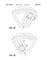
- FIG. 6Aillustrates a perspective view of one embodiment of the gimbal 216 of the present invention.
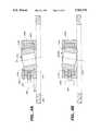
- FIG. 12illustrates a cross-sectional view of the tripod head of FIG. 9, taken along the line 12.
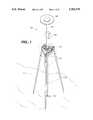
- FIG. 5illustrates a side view of the tripod head of the present invention taken along the line 5 of FIG. 2.
- FIG. 6Aillustrates one embodiment of the gimbal 216 comprising a convex ring.
- the shape of the ring 216is substantially spherical so as to permit it to rotate and/or pivot within the central cavity of second housing 214.
- the gimbalmay comprise a C-shaped ring 216'.
- One advantage of using the C-shaped ring 216' as the gimbal memberis that, as the tightening screw 208 pushes against the gimbal, the gap 216b of the C-shaped ring will become smaller, causing the ring to tighten upon the monopod inserted through its center.
Landscapes
- Engineering & Computer Science (AREA)
- General Engineering & Computer Science (AREA)
- Mechanical Engineering (AREA)
- Physics & Mathematics (AREA)
- General Physics & Mathematics (AREA)
- Radar, Positioning & Navigation (AREA)
- Remote Sensing (AREA)
- Position Fixing By Use Of Radio Waves (AREA)
Abstract
Description
Claims (17)
Priority Applications (1)
| Application Number | Priority Date | Filing Date | Title |
|---|---|---|---|
| US08/647,472US5769370A (en) | 1995-12-29 | 1996-05-08 | Knock-down satellite positioning system antenna supporting tripod |
Applications Claiming Priority (2)
| Application Number | Priority Date | Filing Date | Title |
|---|---|---|---|
| US08/578,169US5749549A (en) | 1995-12-29 | 1995-12-29 | Satellite positioning system antenna supporting tripod |
| US08/647,472US5769370A (en) | 1995-12-29 | 1996-05-08 | Knock-down satellite positioning system antenna supporting tripod |
Related Parent Applications (1)
| Application Number | Title | Priority Date | Filing Date |
|---|---|---|---|
| US08/578,169Continuation-In-PartUS5749549A (en) | 1995-12-29 | 1995-12-29 | Satellite positioning system antenna supporting tripod |
Publications (1)
| Publication Number | Publication Date |
|---|---|
| US5769370Atrue US5769370A (en) | 1998-06-23 |
Family
ID=46251959
Family Applications (1)
| Application Number | Title | Priority Date | Filing Date |
|---|---|---|---|
| US08/647,472Expired - LifetimeUS5769370A (en) | 1995-12-29 | 1996-05-08 | Knock-down satellite positioning system antenna supporting tripod |
Country Status (1)
| Country | Link |
|---|---|
| US (1) | US5769370A (en) |
Cited By (93)
| Publication number | Priority date | Publication date | Assignee | Title |
|---|---|---|---|---|
| WO2000017957A1 (en)* | 1998-09-19 | 2000-03-30 | Nicos Chawales | Device for satellite-aided surveying |
| US6450464B1 (en)* | 2001-01-12 | 2002-09-17 | Elbert Lee Thomas | Satellite dish stand |
| US20030226941A1 (en)* | 2002-04-19 | 2003-12-11 | Crain Enterprises, Inc. | Modular geomatic pole support system |
| US20030235459A1 (en)* | 2002-04-19 | 2003-12-25 | Crain Enterprises, Inc. | Mount and connection system for use with geomatic pole |
| US20040000622A1 (en)* | 2002-04-19 | 2004-01-01 | Crain Enterprises, Inc. | Telescoping leg lock with thumb actuator |
| US20040004168A1 (en)* | 2002-04-19 | 2004-01-08 | Crain Enterprises, Inc. | Geomatic pole support and foot therefor |
| WO2003023435A3 (en)* | 2001-09-11 | 2004-03-25 | Bo Ake Sture Gustafson | Apparatus and methods for locating points of interest |
| US20040075031A1 (en)* | 2002-04-19 | 2004-04-22 | Crain Enterprises, Inc. | Geomatic pole support wtih telescoping legs and locks |
| US20050151035A1 (en)* | 2004-01-13 | 2005-07-14 | Crain Enterprises, Inc. | Multiple function geomatics pole support device |
| USD510699S1 (en) | 2004-01-12 | 2005-10-18 | Crain Enterprises, Inc. | Multiple function geomatics pole support device |
| US20060022873A1 (en)* | 2004-07-30 | 2006-02-02 | Integrinautics Corporation | Synchronizing ranging signals in an asynchronous ranging or position system |
| US20060022870A1 (en)* | 2004-07-30 | 2006-02-02 | Integrinautics Corporation | Land-based local ranging signal methods and systems |
| US20060022872A1 (en)* | 2004-07-30 | 2006-02-02 | Integrinautics Corporation | Asynchronous local position determination system and method |
| US20060022869A1 (en)* | 2004-07-30 | 2006-02-02 | Integirnautics Corporation | Analog decorrelation of ranging signals |
| US20060022871A1 (en)* | 2004-07-30 | 2006-02-02 | Integrinautics Corporation | Land-based transmitter position determination |
| US20060086871A1 (en)* | 2004-10-27 | 2006-04-27 | Council Of Scientific And Industrial Research | Adjustable tripod mechanism to support devices or transducers for scientific measurement |
| US7048241B2 (en) | 2002-04-19 | 2006-05-23 | Crain Enterprises, Inc. | Geomatic support having hinged legs with hinge lock |
| US20060175483A1 (en)* | 2003-03-14 | 2006-08-10 | Osaka Shoji | Panorama support device |
| US20060179917A1 (en)* | 2005-02-16 | 2006-08-17 | Pringle Matthew M | Device and method for measuring the impact properties of a sport field surface |
| US20070040744A1 (en)* | 2004-07-30 | 2007-02-22 | Integrinautics Corporation | Satellite and local system position determination |
| US20070285308A1 (en)* | 2004-07-30 | 2007-12-13 | Integirnautics Corporation | Multiple frequency antenna structures and methods for receiving navigation or ranging signals |
| WO2008077658A1 (en) | 2006-12-22 | 2008-07-03 | Robert Bosch Gmbh | Tripod |
| WO2008112461A1 (en)* | 2007-03-13 | 2008-09-18 | Dycom Identity, Llc | Marking system and method with location and/or time tracking |
| US20090026329A1 (en)* | 2007-07-26 | 2009-01-29 | Shashin Denki Kogyo | Tripod head |
| US20090072100A1 (en)* | 2007-09-07 | 2009-03-19 | Camera Dynamics Gmbh | Spreader for a stand and set comprising the spreader and a tripod |
| US20090115658A1 (en)* | 2004-07-30 | 2009-05-07 | Integrinautics Corporation | Distributed radio frequency ranging signal receiver for navigation or position determination |
| US20100085701A1 (en)* | 2008-10-02 | 2010-04-08 | Certusview Technologies, Llc | Marking device docking stations having security features and methods of using same |
| US20100272885A1 (en)* | 2006-08-16 | 2010-10-28 | SeekTech, Inc., a California corporation | Marking Paint Applicator for Portable Locator |
| CN101980523A (en)* | 2010-10-10 | 2011-02-23 | 任文华 | Tripod head device with communication and positioning function |
| US20110042536A1 (en)* | 2009-08-19 | 2011-02-24 | Thule Organization Solutions, Inc. | Selectively Positionable Device for Securing an Instrument |
| USD634656S1 (en) | 2010-03-01 | 2011-03-22 | Certusview Technologies, Llc | Shaft of a marking device |
| USD634655S1 (en) | 2010-03-01 | 2011-03-22 | Certusview Technologies, Llc | Handle of a marking device |
| USD634657S1 (en) | 2010-03-01 | 2011-03-22 | Certusview Technologies, Llc | Paint holder of a marking device |
| USD643321S1 (en) | 2010-03-01 | 2011-08-16 | Certusview Technologies, Llc | Marking device |
| US8060304B2 (en) | 2007-04-04 | 2011-11-15 | Certusview Technologies, Llc | Marking system and method |
| CN102529442A (en)* | 2011-12-08 | 2012-07-04 | 苏州工业园区高登威科技有限公司 | Adjustable marking device |
| US8280631B2 (en) | 2008-10-02 | 2012-10-02 | Certusview Technologies, Llc | Methods and apparatus for generating an electronic record of a marking operation based on marking device actuations |
| US8311765B2 (en) | 2009-08-11 | 2012-11-13 | Certusview Technologies, Llc | Locating equipment communicatively coupled to or equipped with a mobile/portable device |
| US8400155B2 (en) | 2008-10-02 | 2013-03-19 | Certusview Technologies, Llc | Methods and apparatus for displaying an electronic rendering of a locate operation based on an electronic record of locate information |
| US8442766B2 (en) | 2008-10-02 | 2013-05-14 | Certusview Technologies, Llc | Marking apparatus having enhanced features for underground facility marking operations, and associated methods and systems |
| USD684067S1 (en) | 2012-02-15 | 2013-06-11 | Certusview Technologies, Llc | Modular marking device |
| US8473209B2 (en) | 2007-03-13 | 2013-06-25 | Certusview Technologies, Llc | Marking apparatus and marking methods using marking dispenser with machine-readable ID mechanism |
| US8478523B2 (en) | 2007-03-13 | 2013-07-02 | Certusview Technologies, Llc | Marking apparatus and methods for creating an electronic record of marking apparatus operations |
| US8620572B2 (en) | 2009-08-20 | 2013-12-31 | Certusview Technologies, Llc | Marking device with transmitter for triangulating location during locate operations |
| US8620616B2 (en) | 2009-08-20 | 2013-12-31 | Certusview Technologies, Llc | Methods and apparatus for assessing marking operations based on acceleration information |
| US8626571B2 (en) | 2009-02-11 | 2014-01-07 | Certusview Technologies, Llc | Management system, and associated methods and apparatus, for dispatching tickets, receiving field information, and performing a quality assessment for underground facility locate and/or marking operations |
| US20140311083A1 (en)* | 2013-04-23 | 2014-10-23 | Gabriel Madril | Post stabilization apparatus and method |
| US8965700B2 (en) | 2008-10-02 | 2015-02-24 | Certusview Technologies, Llc | Methods and apparatus for generating an electronic record of environmental landmarks based on marking device actuations |
| US9097522B2 (en) | 2009-08-20 | 2015-08-04 | Certusview Technologies, Llc | Methods and marking devices with mechanisms for indicating and/or detecting marking material color |
| US20150240988A1 (en)* | 2014-02-08 | 2015-08-27 | Franklin B. White | Theft resistant upstanding mount for temporary positioning of costly equipment at unattended outdoor locations |
| US20150292226A1 (en)* | 2014-02-08 | 2015-10-15 | Franklin B. White | Theft resistant upstanding mount for temporary positioning of costly equipment at unattended outdoor locations |
| CN105222748A (en)* | 2015-09-19 | 2016-01-06 | 桂林理工大学 | A kind of transit quick centring leveling support |
| US20160004141A1 (en)* | 2014-07-02 | 2016-01-07 | Shashin Denki Kogyo | Camera platform |
| USD747562S1 (en)* | 2013-12-16 | 2016-01-12 | Fred C. Alford | Wildlife feeder legs |
| US20160076583A1 (en)* | 2013-06-07 | 2016-03-17 | Csaba KARAL | Head assembly for supporting and adjusting the position of an optical or electronic device |
| US20160100083A1 (en)* | 2014-10-02 | 2016-04-07 | Gopro, Inc. | Swivel Camera Mount |
| US20160166049A1 (en)* | 2013-08-28 | 2016-06-16 | Sun Ho Hwang | Support frame |
| US20160274240A1 (en)* | 2015-03-20 | 2016-09-22 | Qualcomm Incorporated | Autonomous satellite automatic gain control |
| WO2017020278A1 (en)* | 2015-08-05 | 2017-02-09 | 深圳市大疆创新科技有限公司 | Bracket and hand-held gimbal platform using same |
| EP3144544A1 (en)* | 2015-09-17 | 2017-03-22 | RK Rose + Krieger GmbH Verbindungs- und Positioniersysteme | Hinge assembly for positioning elements |
| US20180038963A1 (en)* | 2016-08-03 | 2018-02-08 | Topcon Corporation | Position and azimuth measurement device and surveying device |
| US20180259120A1 (en)* | 2017-03-10 | 2018-09-13 | Stanley Lawrence | Survey Support Apparatus |
| US10119818B2 (en)* | 2015-12-17 | 2018-11-06 | Leica Geosystems Ag | Surveying pole |
| US10125513B2 (en)* | 2015-01-15 | 2018-11-13 | Bernhard JECEL | Ground anchor with holder for a load |
| CN108801102A (en)* | 2018-07-12 | 2018-11-13 | 南华大学 | A kind of petroleum geology inspection measuring device |
| EP3434957A4 (en)* | 2016-03-21 | 2019-05-01 | Dalian Senbior Surveying Instrument Technology Co., Ltd. | MEASURING TRIPOD FOR ACCURATE SCALE ANGLE ADJUSTMENT |
| JP2019523892A (en)* | 2017-06-22 | 2019-08-29 | 中山日高精密工業有限公司Zhongshan Nikow Precision Industrial Co., LTD. | Special gimbal head connection structure |
| KR102069117B1 (en)* | 2019-11-07 | 2020-01-22 | 주식회사 삼인공간정보 | Structure of tripod for geodetic surveying |
| KR102069570B1 (en)* | 2019-11-07 | 2020-01-23 | 주식회사 삼인공간정보 | Structure for preventing shock of staff geodetic surveying |
| CN111174769A (en)* | 2020-01-07 | 2020-05-19 | 郑州蓝图土地环境规划设计有限公司 | Measure more accurate engineering survey sighting rod |
| CN111238453A (en)* | 2018-11-28 | 2020-06-05 | 赫克斯冈技术中心 | Intelligent positioning module |
| USD894256S1 (en) | 2018-08-31 | 2020-08-25 | Gopro, Inc. | Camera mount |
| USD905786S1 (en) | 2018-08-31 | 2020-12-22 | Gopro, Inc. | Camera mount |
| US10928711B2 (en) | 2018-08-07 | 2021-02-23 | Gopro, Inc. | Camera and camera mount |
| CN112894311A (en)* | 2021-04-08 | 2021-06-04 | 中国科学院国家天文台 | Device convenient to FAST feed receiver installation and dismantlement |
| KR102320522B1 (en)* | 2021-07-23 | 2021-11-03 | 주식회사 대한측량기술 | Geodetic surveying system for improving precision of leveling and measuring curvature of surface |
| US11226063B2 (en)* | 2016-11-30 | 2022-01-18 | Balázs KÁRMÁN | Top bracket for tripods |
| US11258159B2 (en)* | 2020-03-19 | 2022-02-22 | United States Of America, As Represented By The Secretary Of The Navy | Antenna pedestal |
| CN114576494A (en)* | 2022-03-03 | 2022-06-03 | 合肥筑平建筑工程咨询有限公司 | Building engineering cost on-site mapping device based on BIM technology |
| KR102415007B1 (en)* | 2021-11-15 | 2022-06-30 | 삼아항업(주) | Geodetic survey system whit significantly improved precision |
| KR102502396B1 (en)* | 2022-09-30 | 2023-02-23 | (주)국토해양기술 | Geodetic surveying system for precisely observing survey data based on gis |
| USD991318S1 (en) | 2020-08-14 | 2023-07-04 | Gopro, Inc. | Camera |
| USD997232S1 (en) | 2019-09-17 | 2023-08-29 | Gopro, Inc. | Camera |
| CN116697225A (en)* | 2023-07-31 | 2023-09-05 | 南京长天测绘技术有限公司 | GPS satellite measuring instrument support convenient to fix |
| FR3133231A1 (en)* | 2022-03-07 | 2023-09-08 | Renault | Measuring instrument configured to determine coordinates of a point of interest |
| CN117212643A (en)* | 2023-09-14 | 2023-12-12 | 广东省核工业地质局测绘院 | Geographic information mapping equipment and mapping method thereof |
| USD1020844S1 (en)* | 2022-04-22 | 2024-04-02 | John Whidden | Geomatics instrument carrier |
| CN117948493A (en)* | 2024-03-26 | 2024-04-30 | 玖隆能源建设集团有限公司 | Horizontal angle measuring device |
| USD1036536S1 (en) | 2017-12-28 | 2024-07-23 | Gopro, Inc. | Camera |
| US12321084B2 (en) | 2022-08-12 | 2025-06-03 | Gopro, Inc. | Interconnect mechanism for image capture device |
| US12372225B1 (en)* | 2024-05-15 | 2025-07-29 | Devos, LLC | Tripod for pole mounted lantern |
| US12379650B2 (en) | 2023-02-15 | 2025-08-05 | Gopro, Inc. | Reinforced image capture devices including interconnect mechanisms with a threaded accessory interface |
| USD1096914S1 (en) | 2024-03-15 | 2025-10-07 | Gopro, Inc. | Camera mount |
Citations (10)
| Publication number | Priority date | Publication date | Assignee | Title |
|---|---|---|---|---|
| US209562A (en)* | 1878-11-05 | Improvement in tripod-heads for surveying-instruments | ||
| US3262321A (en)* | 1963-09-16 | 1966-07-26 | Jr George E Moul | Two-rod seeker head |
| US4244547A (en)* | 1978-12-20 | 1981-01-13 | Keuffel & Esser Company | Theodolite leveling means |
| US4317552A (en)* | 1979-12-26 | 1982-03-02 | Weidler Charles H | Universal tripod for supporting a camera or the like |
| US4339880A (en)* | 1978-10-23 | 1982-07-20 | Beverly J. Hall | Device for holding surveyor's instrument |
| US4438896A (en)* | 1981-09-28 | 1984-03-27 | Hall George W | Segmented collar tripod for holding surveyor's stake |
| US4767090A (en)* | 1984-10-23 | 1988-08-30 | Kar-Hart Productions, Inc. | Tripods |
| US5249766A (en)* | 1988-07-06 | 1993-10-05 | Philippe Vogt | Tripod head |
| US5435509A (en)* | 1992-07-15 | 1995-07-25 | Old Stone Corporation | Antenna stand |
| US5614918A (en)* | 1994-06-21 | 1997-03-25 | The United States Of America As Represented By The Administrator Of The National Aeronautics And Space Administration | Global positioning system antenna fixed height tripod adapter |
- 1996
- 1996-05-08USUS08/647,472patent/US5769370A/ennot_activeExpired - Lifetime
Patent Citations (10)
| Publication number | Priority date | Publication date | Assignee | Title |
|---|---|---|---|---|
| US209562A (en)* | 1878-11-05 | Improvement in tripod-heads for surveying-instruments | ||
| US3262321A (en)* | 1963-09-16 | 1966-07-26 | Jr George E Moul | Two-rod seeker head |
| US4339880A (en)* | 1978-10-23 | 1982-07-20 | Beverly J. Hall | Device for holding surveyor's instrument |
| US4244547A (en)* | 1978-12-20 | 1981-01-13 | Keuffel & Esser Company | Theodolite leveling means |
| US4317552A (en)* | 1979-12-26 | 1982-03-02 | Weidler Charles H | Universal tripod for supporting a camera or the like |
| US4438896A (en)* | 1981-09-28 | 1984-03-27 | Hall George W | Segmented collar tripod for holding surveyor's stake |
| US4767090A (en)* | 1984-10-23 | 1988-08-30 | Kar-Hart Productions, Inc. | Tripods |
| US5249766A (en)* | 1988-07-06 | 1993-10-05 | Philippe Vogt | Tripod head |
| US5435509A (en)* | 1992-07-15 | 1995-07-25 | Old Stone Corporation | Antenna stand |
| US5614918A (en)* | 1994-06-21 | 1997-03-25 | The United States Of America As Represented By The Administrator Of The National Aeronautics And Space Administration | Global positioning system antenna fixed height tripod adapter |
Cited By (173)
| Publication number | Priority date | Publication date | Assignee | Title |
|---|---|---|---|---|
| WO2000017957A1 (en)* | 1998-09-19 | 2000-03-30 | Nicos Chawales | Device for satellite-aided surveying |
| US6450464B1 (en)* | 2001-01-12 | 2002-09-17 | Elbert Lee Thomas | Satellite dish stand |
| WO2003023435A3 (en)* | 2001-09-11 | 2004-03-25 | Bo Ake Sture Gustafson | Apparatus and methods for locating points of interest |
| US20060118681A1 (en)* | 2002-04-19 | 2006-06-08 | Crain Enterprises, Inc. | Geomatic support having hinged legs with hinge lock |
| US7631842B2 (en) | 2002-04-19 | 2009-12-15 | Seco Manufacturing Company, Inc. | Modular geomatic pole support system |
| US20040000622A1 (en)* | 2002-04-19 | 2004-01-01 | Crain Enterprises, Inc. | Telescoping leg lock with thumb actuator |
| US20040004168A1 (en)* | 2002-04-19 | 2004-01-08 | Crain Enterprises, Inc. | Geomatic pole support and foot therefor |
| US20040075031A1 (en)* | 2002-04-19 | 2004-04-22 | Crain Enterprises, Inc. | Geomatic pole support wtih telescoping legs and locks |
| US20040227040A1 (en)* | 2002-04-19 | 2004-11-18 | Crain Enterprise, Inc. | Geomatic pole support and foot therefor |
| US7048241B2 (en) | 2002-04-19 | 2006-05-23 | Crain Enterprises, Inc. | Geomatic support having hinged legs with hinge lock |
| US7124985B2 (en) | 2002-04-19 | 2006-10-24 | Crain Enterprises, Inc. | Geomatic pole support with telescoping legs and locks |
| US20060231694A1 (en)* | 2002-04-19 | 2006-10-19 | Crain Enterprises, Inc. | Geomatic pole support with telescoping legs and locks |
| US7207534B2 (en) | 2002-04-19 | 2007-04-24 | Crain Enterprises, Inc. | Geomatic pole support and foot therefor |
| US7222827B2 (en) | 2002-04-19 | 2007-05-29 | Crain Enterprises, Inc. | Telescoping leg lock with thumb actuator |
| US20030226941A1 (en)* | 2002-04-19 | 2003-12-11 | Crain Enterprises, Inc. | Modular geomatic pole support system |
| US7240881B2 (en) | 2002-04-19 | 2007-07-10 | Crain Enterprises, Inc. | Geomatic support having hinged legs with hinge lock |
| US20030235459A1 (en)* | 2002-04-19 | 2003-12-25 | Crain Enterprises, Inc. | Mount and connection system for use with geomatic pole |
| US7374140B2 (en) | 2002-04-19 | 2008-05-20 | Crain Enterprises, Inc. | Geomatic pole support with telescoping legs and locks |
| US20060175483A1 (en)* | 2003-03-14 | 2006-08-10 | Osaka Shoji | Panorama support device |
| USD510699S1 (en) | 2004-01-12 | 2005-10-18 | Crain Enterprises, Inc. | Multiple function geomatics pole support device |
| US7669813B2 (en) | 2004-01-13 | 2010-03-02 | Seco Manufacturing Company, Inc. | Multiple function geomatics pole support device |
| US20050151035A1 (en)* | 2004-01-13 | 2005-07-14 | Crain Enterprises, Inc. | Multiple function geomatics pole support device |
| US7315278B1 (en) | 2004-07-30 | 2008-01-01 | Novariant, Inc. | Multiple frequency antenna structures and methods for receiving navigation or ranging signals |
| US7382318B2 (en) | 2004-07-30 | 2008-06-03 | Novariant Inc. | Land-based local ranging signal methods and systems |
| US20070040744A1 (en)* | 2004-07-30 | 2007-02-22 | Integrinautics Corporation | Satellite and local system position determination |
| US7205939B2 (en) | 2004-07-30 | 2007-04-17 | Novariant, Inc. | Land-based transmitter position determination |
| US20090115658A1 (en)* | 2004-07-30 | 2009-05-07 | Integrinautics Corporation | Distributed radio frequency ranging signal receiver for navigation or position determination |
| US20070109188A1 (en)* | 2004-07-30 | 2007-05-17 | Novariant, Inc. | Satellite and local system position determination |
| US20070115176A1 (en)* | 2004-07-30 | 2007-05-24 | Novariant, Inc. | Land-based local ranging signal methods and systems |
| US20060022872A1 (en)* | 2004-07-30 | 2006-02-02 | Integrinautics Corporation | Asynchronous local position determination system and method |
| US20060022871A1 (en)* | 2004-07-30 | 2006-02-02 | Integrinautics Corporation | Land-based transmitter position determination |
| US20060022870A1 (en)* | 2004-07-30 | 2006-02-02 | Integrinautics Corporation | Land-based local ranging signal methods and systems |
| US7271766B2 (en) | 2004-07-30 | 2007-09-18 | Novariant, Inc. | Satellite and local system position determination |
| US20070285308A1 (en)* | 2004-07-30 | 2007-12-13 | Integirnautics Corporation | Multiple frequency antenna structures and methods for receiving navigation or ranging signals |
| US20060022873A1 (en)* | 2004-07-30 | 2006-02-02 | Integrinautics Corporation | Synchronizing ranging signals in an asynchronous ranging or position system |
| US7339525B2 (en) | 2004-07-30 | 2008-03-04 | Novariant, Inc. | Land-based local ranging signal methods and systems |
| US7339524B2 (en) | 2004-07-30 | 2008-03-04 | Novariant, Inc. | Analog decorrelation of ranging signals |
| US7339526B2 (en) | 2004-07-30 | 2008-03-04 | Novariant, Inc. | Synchronizing ranging signals in an asynchronous ranging or position system |
| US7342538B2 (en) | 2004-07-30 | 2008-03-11 | Novariant, Inc. | Asynchronous local position determination system and method |
| US7345627B2 (en) | 2004-07-30 | 2008-03-18 | Novariant, Inc. | Land-based local ranging signal methods and systems |
| US20060022869A1 (en)* | 2004-07-30 | 2006-02-02 | Integirnautics Corporation | Analog decorrelation of ranging signals |
| US7532160B1 (en) | 2004-07-30 | 2009-05-12 | Novariant, Inc. | Distributed radio frequency ranging signal receiver for navigation or position determination |
| US7385554B2 (en) | 2004-07-30 | 2008-06-10 | Novariant, Inc. | Satellite and local system position determination |
| US20060279461A1 (en)* | 2004-07-30 | 2006-12-14 | Novariant, Inc. | Land-based local ranging signal methods and systems |
| US20060086871A1 (en)* | 2004-10-27 | 2006-04-27 | Council Of Scientific And Industrial Research | Adjustable tripod mechanism to support devices or transducers for scientific measurement |
| US7243526B2 (en)* | 2005-02-16 | 2007-07-17 | United States Golf Association | Device and method for measuring the impact properties of a sport field surface |
| US20060179917A1 (en)* | 2005-02-16 | 2006-08-17 | Pringle Matthew M | Device and method for measuring the impact properties of a sport field surface |
| US20100272885A1 (en)* | 2006-08-16 | 2010-10-28 | SeekTech, Inc., a California corporation | Marking Paint Applicator for Portable Locator |
| WO2008077658A1 (en) | 2006-12-22 | 2008-07-03 | Robert Bosch Gmbh | Tripod |
| US8903643B2 (en) | 2007-03-13 | 2014-12-02 | Certusview Technologies, Llc | Hand-held marking apparatus with location tracking system and methods for logging geographic location of same |
| US8700325B2 (en) | 2007-03-13 | 2014-04-15 | Certusview Technologies, Llc | Marking apparatus and methods for creating an electronic record of marking operations |
| US8401791B2 (en) | 2007-03-13 | 2013-03-19 | Certusview Technologies, Llc | Methods for evaluating operation of marking apparatus |
| US7640105B2 (en) | 2007-03-13 | 2009-12-29 | Certus View Technologies, LLC | Marking system and method with location and/or time tracking |
| US8407001B2 (en) | 2007-03-13 | 2013-03-26 | Certusview Technologies, Llc | Systems and methods for using location data to electronically display dispensing of markers by a marking system or marking tool |
| US9086277B2 (en) | 2007-03-13 | 2015-07-21 | Certusview Technologies, Llc | Electronically controlled marking apparatus and methods |
| US20080228294A1 (en)* | 2007-03-13 | 2008-09-18 | Dycom Identity, Llc | Marking system and method with location and/or time tracking |
| WO2008112461A1 (en)* | 2007-03-13 | 2008-09-18 | Dycom Identity, Llc | Marking system and method with location and/or time tracking |
| US8775077B2 (en) | 2007-03-13 | 2014-07-08 | Certusview Technologies, Llc | Systems and methods for using location data to electronically display dispensing of markers by a marking system or marking tool |
| US8473209B2 (en) | 2007-03-13 | 2013-06-25 | Certusview Technologies, Llc | Marking apparatus and marking methods using marking dispenser with machine-readable ID mechanism |
| US8478523B2 (en) | 2007-03-13 | 2013-07-02 | Certusview Technologies, Llc | Marking apparatus and methods for creating an electronic record of marking apparatus operations |
| US8374789B2 (en) | 2007-04-04 | 2013-02-12 | Certusview Technologies, Llc | Systems and methods for using marking information to electronically display dispensing of markers by a marking system or marking tool |
| US8060304B2 (en) | 2007-04-04 | 2011-11-15 | Certusview Technologies, Llc | Marking system and method |
| US8386178B2 (en) | 2007-04-04 | 2013-02-26 | Certusview Technologies, Llc | Marking system and method |
| US7984882B2 (en)* | 2007-07-26 | 2011-07-26 | Shashin Denki Kogyo | Tripod head |
| US20090026329A1 (en)* | 2007-07-26 | 2009-01-29 | Shashin Denki Kogyo | Tripod head |
| US8534620B2 (en) | 2007-09-07 | 2013-09-17 | Camera Dynamics Gmbh | Spreader for a stand and set comprising the spreader and a tripod |
| US20090072100A1 (en)* | 2007-09-07 | 2009-03-19 | Camera Dynamics Gmbh | Spreader for a stand and set comprising the spreader and a tripod |
| CN101382231B (en)* | 2007-09-07 | 2012-09-05 | 照相机动力有限责任公司 | Spider for a stand and set containing the spider and a tripod stand |
| EP2034231A3 (en)* | 2007-09-07 | 2009-12-16 | Camera Dynamics GmbH | Spider for a stand and set containing the spider and a tripod stand |
| US8612148B2 (en) | 2008-10-02 | 2013-12-17 | Certusview Technologies, Llc | Marking apparatus configured to detect out-of-tolerance conditions in connection with underground facility marking operations, and associated methods and systems |
| US8478524B2 (en) | 2008-10-02 | 2013-07-02 | Certusview Technologies, Llc | Methods and apparatus for dispensing marking material in connection with underground facility marking operations based on environmental information and/or operational information |
| US8770140B2 (en) | 2008-10-02 | 2014-07-08 | Certusview Technologies, Llc | Marking apparatus having environmental sensors and operations sensors for underground facility marking operations, and associated methods and systems |
| US8280631B2 (en) | 2008-10-02 | 2012-10-02 | Certusview Technologies, Llc | Methods and apparatus for generating an electronic record of a marking operation based on marking device actuations |
| US8400155B2 (en) | 2008-10-02 | 2013-03-19 | Certusview Technologies, Llc | Methods and apparatus for displaying an electronic rendering of a locate operation based on an electronic record of locate information |
| US8361543B2 (en) | 2008-10-02 | 2013-01-29 | Certusview Technologies, Llc | Methods and apparatus for displaying an electronic rendering of a marking operation based on an electronic record of marking information |
| US8442766B2 (en) | 2008-10-02 | 2013-05-14 | Certusview Technologies, Llc | Marking apparatus having enhanced features for underground facility marking operations, and associated methods and systems |
| US8457893B2 (en) | 2008-10-02 | 2013-06-04 | Certusview Technologies, Llc | Methods and apparatus for generating an electronic record of a marking operation including service-related information and/or ticket information |
| US9542863B2 (en) | 2008-10-02 | 2017-01-10 | Certusview Technologies, Llc | Methods and apparatus for generating output data streams relating to underground utility marking operations |
| US8467969B2 (en) | 2008-10-02 | 2013-06-18 | Certusview Technologies, Llc | Marking apparatus having operational sensors for underground facility marking operations, and associated methods and systems |
| US8731830B2 (en) | 2008-10-02 | 2014-05-20 | Certusview Technologies, Llc | Marking apparatus for receiving environmental information regarding underground facility marking operations, and associated methods and systems |
| US8478525B2 (en) | 2008-10-02 | 2013-07-02 | Certusview Technologies, Llc | Methods, apparatus, and systems for analyzing use of a marking device by a technician to perform an underground facility marking operation |
| US8644965B2 (en) | 2008-10-02 | 2014-02-04 | Certusview Technologies, Llc | Marking device docking stations having security features and methods of using same |
| US8965700B2 (en) | 2008-10-02 | 2015-02-24 | Certusview Technologies, Llc | Methods and apparatus for generating an electronic record of environmental landmarks based on marking device actuations |
| US20100085701A1 (en)* | 2008-10-02 | 2010-04-08 | Certusview Technologies, Llc | Marking device docking stations having security features and methods of using same |
| US8583264B2 (en) | 2008-10-02 | 2013-11-12 | Certusview Technologies, Llc | Marking device docking stations and methods of using same |
| US8600526B2 (en) | 2008-10-02 | 2013-12-03 | Certusview Technologies, Llc | Marking device docking stations having mechanical docking and methods of using same |
| US8626571B2 (en) | 2009-02-11 | 2014-01-07 | Certusview Technologies, Llc | Management system, and associated methods and apparatus, for dispatching tickets, receiving field information, and performing a quality assessment for underground facility locate and/or marking operations |
| US8731999B2 (en) | 2009-02-11 | 2014-05-20 | Certusview Technologies, Llc | Management system, and associated methods and apparatus, for providing improved visibility, quality control and audit capability for underground facility locate and/or marking operations |
| US9185176B2 (en) | 2009-02-11 | 2015-11-10 | Certusview Technologies, Llc | Methods and apparatus for managing locate and/or marking operations |
| US8311765B2 (en) | 2009-08-11 | 2012-11-13 | Certusview Technologies, Llc | Locating equipment communicatively coupled to or equipped with a mobile/portable device |
| US20110042536A1 (en)* | 2009-08-19 | 2011-02-24 | Thule Organization Solutions, Inc. | Selectively Positionable Device for Securing an Instrument |
| US20110042530A1 (en)* | 2009-08-19 | 2011-02-24 | Mark Phillips | Flexipod with flexible bendable legs with a gripping surface |
| US8620572B2 (en) | 2009-08-20 | 2013-12-31 | Certusview Technologies, Llc | Marking device with transmitter for triangulating location during locate operations |
| US8620616B2 (en) | 2009-08-20 | 2013-12-31 | Certusview Technologies, Llc | Methods and apparatus for assessing marking operations based on acceleration information |
| US9097522B2 (en) | 2009-08-20 | 2015-08-04 | Certusview Technologies, Llc | Methods and marking devices with mechanisms for indicating and/or detecting marking material color |
| USD634657S1 (en) | 2010-03-01 | 2011-03-22 | Certusview Technologies, Llc | Paint holder of a marking device |
| USD643321S1 (en) | 2010-03-01 | 2011-08-16 | Certusview Technologies, Llc | Marking device |
| USD634656S1 (en) | 2010-03-01 | 2011-03-22 | Certusview Technologies, Llc | Shaft of a marking device |
| USD634655S1 (en) | 2010-03-01 | 2011-03-22 | Certusview Technologies, Llc | Handle of a marking device |
| CN101980523A (en)* | 2010-10-10 | 2011-02-23 | 任文华 | Tripod head device with communication and positioning function |
| CN102529442A (en)* | 2011-12-08 | 2012-07-04 | 苏州工业园区高登威科技有限公司 | Adjustable marking device |
| USD684067S1 (en) | 2012-02-15 | 2013-06-11 | Certusview Technologies, Llc | Modular marking device |
| US9187920B2 (en)* | 2013-04-23 | 2015-11-17 | Gabriel Madril | Post stabilization apparatus and method |
| US8991777B2 (en)* | 2013-04-23 | 2015-03-31 | Gabriel Madril | Post stabilization apparatus and method |
| US20150167341A1 (en)* | 2013-04-23 | 2015-06-18 | Gabriel Madril | Post stabilization apparatus and method |
| US20140311083A1 (en)* | 2013-04-23 | 2014-10-23 | Gabriel Madril | Post stabilization apparatus and method |
| US20160076583A1 (en)* | 2013-06-07 | 2016-03-17 | Csaba KARAL | Head assembly for supporting and adjusting the position of an optical or electronic device |
| US10626912B2 (en)* | 2013-06-07 | 2020-04-21 | Csaba Karal | Head assembly for supporting and adjusting the position of an optical or electronic device |
| US20160166049A1 (en)* | 2013-08-28 | 2016-06-16 | Sun Ho Hwang | Support frame |
| US9687065B2 (en)* | 2013-08-28 | 2017-06-27 | Sun Ho Hwang | Support frame |
| USD747562S1 (en)* | 2013-12-16 | 2016-01-12 | Fred C. Alford | Wildlife feeder legs |
| US9803794B2 (en)* | 2014-02-08 | 2017-10-31 | Franklin B White | Theft resistant upstanding mount for temporary support of costly equipment likely to be a target for theft |
| US20150240988A1 (en)* | 2014-02-08 | 2015-08-27 | Franklin B. White | Theft resistant upstanding mount for temporary positioning of costly equipment at unattended outdoor locations |
| US9534731B2 (en)* | 2014-02-08 | 2017-01-03 | Franklin B White | Theft resistant upstanding mount for temporary positioning of costly equipment at unattended outdoor locations |
| US9637942B2 (en)* | 2014-02-08 | 2017-05-02 | Franklin B. White | Theft resistant upstanding mount for temporary positioning of costly equipment at unattended outdoor locations |
| US20150292226A1 (en)* | 2014-02-08 | 2015-10-15 | Franklin B. White | Theft resistant upstanding mount for temporary positioning of costly equipment at unattended outdoor locations |
| US20160004141A1 (en)* | 2014-07-02 | 2016-01-07 | Shashin Denki Kogyo | Camera platform |
| US9681029B2 (en)* | 2014-10-02 | 2017-06-13 | Gopro, Inc. | Swivel camera mount |
| US20170272626A1 (en)* | 2014-10-02 | 2017-09-21 | Gopro, Inc. | Swivel Camera Mount |
| US20160100083A1 (en)* | 2014-10-02 | 2016-04-07 | Gopro, Inc. | Swivel Camera Mount |
| US10547769B2 (en) | 2014-10-02 | 2020-01-28 | Gopro, Inc. | Swivel camera mount |
| US10125513B2 (en)* | 2015-01-15 | 2018-11-13 | Bernhard JECEL | Ground anchor with holder for a load |
| US20160274240A1 (en)* | 2015-03-20 | 2016-09-22 | Qualcomm Incorporated | Autonomous satellite automatic gain control |
| US10641901B2 (en)* | 2015-03-20 | 2020-05-05 | Qualcomm Incorporated | Autonomous satellite automatic gain control |
| WO2017020278A1 (en)* | 2015-08-05 | 2017-02-09 | 深圳市大疆创新科技有限公司 | Bracket and hand-held gimbal platform using same |
| EP3144544A1 (en)* | 2015-09-17 | 2017-03-22 | RK Rose + Krieger GmbH Verbindungs- und Positioniersysteme | Hinge assembly for positioning elements |
| CN105222748A (en)* | 2015-09-19 | 2016-01-06 | 桂林理工大学 | A kind of transit quick centring leveling support |
| US10119818B2 (en)* | 2015-12-17 | 2018-11-06 | Leica Geosystems Ag | Surveying pole |
| EP3434957A4 (en)* | 2016-03-21 | 2019-05-01 | Dalian Senbior Surveying Instrument Technology Co., Ltd. | MEASURING TRIPOD FOR ACCURATE SCALE ANGLE ADJUSTMENT |
| US11402054B2 (en)* | 2016-03-21 | 2022-08-02 | Dalian Senbior Surveying Instrument Technology Co., Ltd. | Surveying stand capable of precisely adjusting angle of scale |
| US20180038963A1 (en)* | 2016-08-03 | 2018-02-08 | Topcon Corporation | Position and azimuth measurement device and surveying device |
| US11226063B2 (en)* | 2016-11-30 | 2022-01-18 | Balázs KÁRMÁN | Top bracket for tripods |
| US20180259120A1 (en)* | 2017-03-10 | 2018-09-13 | Stanley Lawrence | Survey Support Apparatus |
| US10591109B2 (en)* | 2017-03-10 | 2020-03-17 | Stanley Lawrence | Survey support apparatus |
| JP2019523892A (en)* | 2017-06-22 | 2019-08-29 | 中山日高精密工業有限公司Zhongshan Nikow Precision Industrial Co., LTD. | Special gimbal head connection structure |
| USD1079788S1 (en) | 2017-12-28 | 2025-06-17 | Gopro, Inc. | Camera |
| USD1036536S1 (en) | 2017-12-28 | 2024-07-23 | Gopro, Inc. | Camera |
| CN108801102A (en)* | 2018-07-12 | 2018-11-13 | 南华大学 | A kind of petroleum geology inspection measuring device |
| US11662651B2 (en) | 2018-08-07 | 2023-05-30 | Gopro, Inc. | Camera and camera mount |
| US10928711B2 (en) | 2018-08-07 | 2021-02-23 | Gopro, Inc. | Camera and camera mount |
| US12399419B2 (en) | 2018-08-07 | 2025-08-26 | Gopro, Inc. | Camera and camera mount |
| USD894256S1 (en) | 2018-08-31 | 2020-08-25 | Gopro, Inc. | Camera mount |
| USD905786S1 (en) | 2018-08-31 | 2020-12-22 | Gopro, Inc. | Camera mount |
| USD1023115S1 (en) | 2018-08-31 | 2024-04-16 | Gopro, Inc. | Camera mount |
| USD989165S1 (en) | 2018-08-31 | 2023-06-13 | Gopro, Inc. | Camera mount |
| CN111238453A (en)* | 2018-11-28 | 2020-06-05 | 赫克斯冈技术中心 | Intelligent positioning module |
| CN111238453B (en)* | 2018-11-28 | 2023-09-05 | 赫克斯冈技术中心 | Intelligent positioning module |
| USD1024165S1 (en) | 2019-09-17 | 2024-04-23 | Gopro, Inc. | Camera |
| USD1090676S1 (en) | 2019-09-17 | 2025-08-26 | Gopro, Inc. | Camera |
| USD997232S1 (en) | 2019-09-17 | 2023-08-29 | Gopro, Inc. | Camera |
| KR102069117B1 (en)* | 2019-11-07 | 2020-01-22 | 주식회사 삼인공간정보 | Structure of tripod for geodetic surveying |
| KR102069570B1 (en)* | 2019-11-07 | 2020-01-23 | 주식회사 삼인공간정보 | Structure for preventing shock of staff geodetic surveying |
| CN111174769A (en)* | 2020-01-07 | 2020-05-19 | 郑州蓝图土地环境规划设计有限公司 | Measure more accurate engineering survey sighting rod |
| US11258159B2 (en)* | 2020-03-19 | 2022-02-22 | United States Of America, As Represented By The Secretary Of The Navy | Antenna pedestal |
| USD991318S1 (en) | 2020-08-14 | 2023-07-04 | Gopro, Inc. | Camera |
| USD1004676S1 (en) | 2020-08-14 | 2023-11-14 | Gopro, Inc. | Camera |
| CN112894311A (en)* | 2021-04-08 | 2021-06-04 | 中国科学院国家天文台 | Device convenient to FAST feed receiver installation and dismantlement |
| KR102320522B1 (en)* | 2021-07-23 | 2021-11-03 | 주식회사 대한측량기술 | Geodetic surveying system for improving precision of leveling and measuring curvature of surface |
| KR102415007B1 (en)* | 2021-11-15 | 2022-06-30 | 삼아항업(주) | Geodetic survey system whit significantly improved precision |
| CN114576494B (en)* | 2022-03-03 | 2023-10-24 | 上海沪港建设咨询有限公司 | Building engineering cost on-site mapping device based on BIM technology |
| CN114576494A (en)* | 2022-03-03 | 2022-06-03 | 合肥筑平建筑工程咨询有限公司 | Building engineering cost on-site mapping device based on BIM technology |
| FR3133231A1 (en)* | 2022-03-07 | 2023-09-08 | Renault | Measuring instrument configured to determine coordinates of a point of interest |
| USD1020844S1 (en)* | 2022-04-22 | 2024-04-02 | John Whidden | Geomatics instrument carrier |
| US12321084B2 (en) | 2022-08-12 | 2025-06-03 | Gopro, Inc. | Interconnect mechanism for image capture device |
| KR102502396B1 (en)* | 2022-09-30 | 2023-02-23 | (주)국토해양기술 | Geodetic surveying system for precisely observing survey data based on gis |
| US12379650B2 (en) | 2023-02-15 | 2025-08-05 | Gopro, Inc. | Reinforced image capture devices including interconnect mechanisms with a threaded accessory interface |
| CN116697225A (en)* | 2023-07-31 | 2023-09-05 | 南京长天测绘技术有限公司 | GPS satellite measuring instrument support convenient to fix |
| CN116697225B (en)* | 2023-07-31 | 2023-09-26 | 南京长天测绘技术有限公司 | GPS satellite measuring instrument support convenient to fix |
| CN117212643A (en)* | 2023-09-14 | 2023-12-12 | 广东省核工业地质局测绘院 | Geographic information mapping equipment and mapping method thereof |
| CN117212643B (en)* | 2023-09-14 | 2024-02-27 | 广东省核工业地质局测绘院 | Geographic information mapping equipment and mapping method thereof |
| USD1096914S1 (en) | 2024-03-15 | 2025-10-07 | Gopro, Inc. | Camera mount |
| CN117948493A (en)* | 2024-03-26 | 2024-04-30 | 玖隆能源建设集团有限公司 | Horizontal angle measuring device |
| US12372225B1 (en)* | 2024-05-15 | 2025-07-29 | Devos, LLC | Tripod for pole mounted lantern |
Similar Documents
| Publication | Publication Date | Title |
|---|---|---|
| US5769370A (en) | Knock-down satellite positioning system antenna supporting tripod | |
| US5749549A (en) | Satellite positioning system antenna supporting tripod | |
| US5614918A (en) | Global positioning system antenna fixed height tripod adapter | |
| US7611105B1 (en) | Corner prism pole and stand | |
| JP2874776B2 (en) | Surveying instrument having receiver for position measurement system using satellite and method of using the same | |
| US6052083A (en) | Method and apparatus for position identification | |
| US5760748A (en) | Pivoting support bracket to mount a GPS antenna above a theodolite or a total station mounted on a tripod | |
| KR100288885B1 (en) | Tripod for a surveying instrument | |
| US9746324B1 (en) | Adjustable high precision surveying device | |
| US7987605B2 (en) | Reflector target tripod for survey system with light emitter and pivoting bracket for enhanced ground marking accuracy | |
| KR100928662B1 (en) | A multipurpose instrument | |
| US6453569B1 (en) | Surveying instrument and plumbing device for plumbing surveying instrument | |
| US6701631B1 (en) | Convertible directional azimuth and dip measuring modular compass and method | |
| US4926561A (en) | Tripod stand for a surveyor's rod | |
| US20050151035A1 (en) | Multiple function geomatics pole support device | |
| GB2075676A (en) | Gyroscopic surveying means and method of operating such means | |
| US7604208B2 (en) | Height adjustable, platform leveling multi-pod | |
| US20110252655A1 (en) | Apparatus and methods for surveying with a hydrant monument | |
| US5046259A (en) | Underwater measuring systems and methods | |
| US6526667B1 (en) | Satellite spacecraft targeting device and method | |
| KR101910433B1 (en) | Apparatus for fixing leveling equipment and triangle stand | |
| GB2344654A (en) | Survey and navigation device | |
| CA1066093A (en) | Rate integrating gyroscopic aiming method and device therefor | |
| CA2734432A1 (en) | Apparatus and methods for surveying with a hydrant monument | |
| CN116838901A (en) | An adaptive positioning device for engineering surveying and mapping instruments |
Legal Events
| Date | Code | Title | Description |
|---|---|---|---|
| AS | Assignment | Owner name:JAVAD POSITIONING, LLC, CALIFORNIA Free format text:ASSIGNMENT OF ASSIGNORS INTEREST;ASSIGNOR:ASHJAEE, JAVAD;REEL/FRAME:008594/0315 Effective date:19970513 | |
| STCF | Information on status: patent grant | Free format text:PATENTED CASE | |
| CC | Certificate of correction | ||
| AS | Assignment | Owner name:JAVAD POSITIONING SYSTEMS, INC., CALIFORNIA Free format text:MERGER;ASSIGNOR:JAVAD POSITIONING SYSTEMS, LLC;REEL/FRAME:011575/0612 Effective date:20000710 | |
| AS | Assignment | Owner name:TOPCON POSITIONING SYSTEMS, INC., CALIFORNIA Free format text:CHANGE OF NAME;ASSIGNOR:JAVAD POSITIONING SYSTEMS, INC.;REEL/FRAME:011667/0918 Effective date:20000901 | |
| AS | Assignment | Owner name:TOPCON POSITION SYSTEMS, INC., CALIFORNIA Free format text:ASSIGNMENT OF ASSIGNORS INTEREST;ASSIGNOR:ACCURATE POSITIONING SYSTEMS, INC.;REEL/FRAME:012232/0980 Effective date:20010701 Owner name:TOPCON GPS LLC, CALIFORNIA Free format text:ASSIGNMENT OF ASSIGNORS INTEREST;ASSIGNOR:TOPCON POSITIONING SYSTEMS, INC.;REEL/FRAME:012243/0001 Effective date:20010701 Owner name:ACCURATE POSITIONING SYSTEMS, INC., CALIFORNIA Free format text:CHANGE OF NAME;ASSIGNOR:TOPCON POSITIONING SYSTEMS, INC.;REEL/FRAME:012243/0241 Effective date:20010605 | |
| FPAY | Fee payment | Year of fee payment:4 | |
| FEPP | Fee payment procedure | Free format text:PAT HOLDER NO LONGER CLAIMS SMALL ENTITY STATUS, ENTITY STATUS SET TO UNDISCOUNTED (ORIGINAL EVENT CODE: STOL); ENTITY STATUS OF PATENT OWNER: LARGE ENTITY | |
| REFU | Refund | Free format text:REFUND - PAYMENT OF MAINTENANCE FEE, 8TH YR, SMALL ENTITY (ORIGINAL EVENT CODE: R2552); ENTITY STATUS OF PATENT OWNER: LARGE ENTITY | |
| FPAY | Fee payment | Year of fee payment:8 | |
| FPAY | Fee payment | Year of fee payment:12 |