US5769184A - Coaxial drive elevator - Google Patents
Coaxial drive elevatorDownload PDFInfo
- Publication number
- US5769184A US5769184AUS08/722,353US72235396AUS5769184AUS 5769184 AUS5769184 AUS 5769184AUS 72235396 AUS72235396 AUS 72235396AUS 5769184 AUS5769184 AUS 5769184A
- Authority
- US
- United States
- Prior art keywords
- drive
- further characterized
- rotary shaft
- elevator mechanism
- drives
- Prior art date
- Legal status (The legal status is an assumption and is not a legal conclusion. Google has not performed a legal analysis and makes no representation as to the accuracy of the status listed.)
- Expired - Lifetime
Links
Images


Classifications
- H—ELECTRICITY
- H01—ELECTRIC ELEMENTS
- H01L—SEMICONDUCTOR DEVICES NOT COVERED BY CLASS H10
- H01L21/00—Processes or apparatus adapted for the manufacture or treatment of semiconductor or solid state devices or of parts thereof
- H01L21/67—Apparatus specially adapted for handling semiconductor or electric solid state devices during manufacture or treatment thereof; Apparatus specially adapted for handling wafers during manufacture or treatment of semiconductor or electric solid state devices or components ; Apparatus not specifically provided for elsewhere
- H01L21/677—Apparatus specially adapted for handling semiconductor or electric solid state devices during manufacture or treatment thereof; Apparatus specially adapted for handling wafers during manufacture or treatment of semiconductor or electric solid state devices or components ; Apparatus not specifically provided for elsewhere for conveying, e.g. between different workstations
- H01L21/67763—Apparatus specially adapted for handling semiconductor or electric solid state devices during manufacture or treatment thereof; Apparatus specially adapted for handling wafers during manufacture or treatment of semiconductor or electric solid state devices or components ; Apparatus not specifically provided for elsewhere for conveying, e.g. between different workstations the wafers being stored in a carrier, involving loading and unloading
- H01L21/67778—Apparatus specially adapted for handling semiconductor or electric solid state devices during manufacture or treatment thereof; Apparatus specially adapted for handling wafers during manufacture or treatment of semiconductor or electric solid state devices or components ; Apparatus not specifically provided for elsewhere for conveying, e.g. between different workstations the wafers being stored in a carrier, involving loading and unloading involving loading and unloading of wafers
- H01L21/67781—Batch transfer of wafers
- B—PERFORMING OPERATIONS; TRANSPORTING
- B66—HOISTING; LIFTING; HAULING
- B66B—ELEVATORS; ESCALATORS OR MOVING WALKWAYS
- B66B9/00—Kinds or types of lifts in, or associated with, buildings or other structures
- B66B9/02—Kinds or types of lifts in, or associated with, buildings or other structures actuated mechanically otherwise than by rope or cable
- H—ELECTRICITY
- H01—ELECTRIC ELEMENTS
- H01L—SEMICONDUCTOR DEVICES NOT COVERED BY CLASS H10
- H01L21/00—Processes or apparatus adapted for the manufacture or treatment of semiconductor or solid state devices or of parts thereof
- H01L21/67—Apparatus specially adapted for handling semiconductor or electric solid state devices during manufacture or treatment thereof; Apparatus specially adapted for handling wafers during manufacture or treatment of semiconductor or electric solid state devices or components ; Apparatus not specifically provided for elsewhere
- H01L21/67005—Apparatus not specifically provided for elsewhere
- H01L21/67011—Apparatus for manufacture or treatment
- H01L21/67155—Apparatus for manufacturing or treating in a plurality of work-stations
- H01L21/67201—Apparatus for manufacturing or treating in a plurality of work-stations characterized by the construction of the load-lock chamber
- H—ELECTRICITY
- H01—ELECTRIC ELEMENTS
- H01L—SEMICONDUCTOR DEVICES NOT COVERED BY CLASS H10
- H01L21/00—Processes or apparatus adapted for the manufacture or treatment of semiconductor or solid state devices or of parts thereof
- H01L21/67—Apparatus specially adapted for handling semiconductor or electric solid state devices during manufacture or treatment thereof; Apparatus specially adapted for handling wafers during manufacture or treatment of semiconductor or electric solid state devices or components ; Apparatus not specifically provided for elsewhere
- H01L21/677—Apparatus specially adapted for handling semiconductor or electric solid state devices during manufacture or treatment thereof; Apparatus specially adapted for handling wafers during manufacture or treatment of semiconductor or electric solid state devices or components ; Apparatus not specifically provided for elsewhere for conveying, e.g. between different workstations
- H01L21/67763—Apparatus specially adapted for handling semiconductor or electric solid state devices during manufacture or treatment thereof; Apparatus specially adapted for handling wafers during manufacture or treatment of semiconductor or electric solid state devices or components ; Apparatus not specifically provided for elsewhere for conveying, e.g. between different workstations the wafers being stored in a carrier, involving loading and unloading
- H01L21/67766—Mechanical parts of transfer devices
- H—ELECTRICITY
- H01—ELECTRIC ELEMENTS
- H01L—SEMICONDUCTOR DEVICES NOT COVERED BY CLASS H10
- H01L21/00—Processes or apparatus adapted for the manufacture or treatment of semiconductor or solid state devices or of parts thereof
- H01L21/67—Apparatus specially adapted for handling semiconductor or electric solid state devices during manufacture or treatment thereof; Apparatus specially adapted for handling wafers during manufacture or treatment of semiconductor or electric solid state devices or components ; Apparatus not specifically provided for elsewhere
- H01L21/677—Apparatus specially adapted for handling semiconductor or electric solid state devices during manufacture or treatment thereof; Apparatus specially adapted for handling wafers during manufacture or treatment of semiconductor or electric solid state devices or components ; Apparatus not specifically provided for elsewhere for conveying, e.g. between different workstations
- H01L21/67763—Apparatus specially adapted for handling semiconductor or electric solid state devices during manufacture or treatment thereof; Apparatus specially adapted for handling wafers during manufacture or treatment of semiconductor or electric solid state devices or components ; Apparatus not specifically provided for elsewhere for conveying, e.g. between different workstations the wafers being stored in a carrier, involving loading and unloading
- H01L21/67778—Apparatus specially adapted for handling semiconductor or electric solid state devices during manufacture or treatment thereof; Apparatus specially adapted for handling wafers during manufacture or treatment of semiconductor or electric solid state devices or components ; Apparatus not specifically provided for elsewhere for conveying, e.g. between different workstations the wafers being stored in a carrier, involving loading and unloading involving loading and unloading of wafers
- F—MECHANICAL ENGINEERING; LIGHTING; HEATING; WEAPONS; BLASTING
- F16—ENGINEERING ELEMENTS AND UNITS; GENERAL MEASURES FOR PRODUCING AND MAINTAINING EFFECTIVE FUNCTIONING OF MACHINES OR INSTALLATIONS; THERMAL INSULATION IN GENERAL
- F16H—GEARING
- F16H25/00—Gearings comprising primarily only cams, cam-followers and screw-and-nut mechanisms
- F16H25/18—Gearings comprising primarily only cams, cam-followers and screw-and-nut mechanisms for conveying or interconverting oscillating or reciprocating motions
- F16H25/20—Screw mechanisms
- F16H2025/2062—Arrangements for driving the actuator
- F16H2025/2081—Parallel arrangement of drive motor to screw axis
- Y—GENERAL TAGGING OF NEW TECHNOLOGICAL DEVELOPMENTS; GENERAL TAGGING OF CROSS-SECTIONAL TECHNOLOGIES SPANNING OVER SEVERAL SECTIONS OF THE IPC; TECHNICAL SUBJECTS COVERED BY FORMER USPC CROSS-REFERENCE ART COLLECTIONS [XRACs] AND DIGESTS
- Y10—TECHNICAL SUBJECTS COVERED BY FORMER USPC
- Y10T—TECHNICAL SUBJECTS COVERED BY FORMER US CLASSIFICATION
- Y10T74/00—Machine element or mechanism
- Y10T74/18—Mechanical movements
- Y10T74/18568—Reciprocating or oscillating to or from alternating rotary
- Y10T74/18576—Reciprocating or oscillating to or from alternating rotary including screw and nut
Definitions
- the apparatus of the present inventionrelates generally to material transfer devices.
- the material transferredmight include, but not be limited to, semiconductor wafers, such as Silicon and Gallium Arsenide, semiconductor packaging substrates, such as High Density Interconnects, semiconductor manufacturing process imaging plates, such as masks or reticles, and large area display panels, such as Active Matrix LCD substrates.
- the present inventionrelates generally to material transfer devices, and in particular, to a coaxially drive elevator used to effect rotation and vertical movement of substrate holders in material transfer devices for the production of substrates which may take the form of semiconductor wafers and or flat panels, or other substrates, or media.
- an object of the present inventionto provide an article transfer mechanism for moving an article between first and second stations in a straight linear path with repeatability of movement and which mechanism is articulated by a drive which both rotates and vertically moves the mechanism about and along a given axis.
- Still a further object of the inventionis to provide an elevator mechanism of the aforementioned type which utilizes a compact drive arrangement to provide increased stroke length relative to a given housing size.
- Still a further object of the inventionis to provide a transport mechanism which is capable of functioning in a clean room environment.
- the present inventionresides in an elevator mechanism comprising a base plate defining the bottom wall of a chamber disposed above the base plate, the base plate having a top surface and a bottom surface with an opening therein communicating between the top and bottom surfaces.
- a first driveis disposed for movement parallel to a first given direction below the base plate.
- a carriageis connected for movement to the first drive and carries a lift tube extended upwards from the carriage along the given direction and through the opening in the base plate.
- the lift tubeincludes a coaxially disposed rotary shaft therewithin and is supported on the carriage.
- a second drive having an outputis provided and is supported on the carriage for rotating the rotary shaft in either direction.
- the first drive outputis disposed parallel to the given direction and spaced from the rotary shaft in a side-by-side orientation.
- a coupling meansis also provided for drivingly connecting the output of the second drive to the rotary shaft.
- the inventionfurther resides in a rotary linear drive having a base and a linear positioning device extending in a given direction with first and second ends secured within the base.
- a first rotary driveis secured to the base and is drivingly coupled to the linear positioning device.
- a carriageis connected to the linear positioning device for movement along the given direction in response to energization and reverse energization of the first rotary drive.
- the carriagehas a support base surface which extends generally perpendicularly to the first given direction.
- a lift tubeis supported on the support base at the lower end thereof and has a hollow internal confine for receiving a rotary shaft therein.
- the rotary shafthas a length longer than the length of the lift tube so as to extend upwardly beyond one end of the lift tube and to depend downwardly therefrom and through an opening formed in the support base to define a depending connecting portion thereon.
- a second driveis mounted to the carriage and has an output for causing rotation of the rotary shaft.
- a coupling meansis provided for drivingly coupling the output of the second drive to the rotary shaft for effecting rotation in either rotational direction.
- the ON and OFF conditions of the first and second drivesbeing controlled by a control means.
- FIG. 1is a partially fragmentary top plan diagrammatic view of a pair of side by side processing stations of the type capable of utilizing the transfer apparatus of the invention.
- FIG. 2is a partially fragmentary side elevation view of the processing station illustrated in FIG. 1.
- FIG. 3is a top plan partially fragmentary diagrammatic view illustrating, in greater detail, a single one of the processing stations of FIG. 1 and utilizing a transfer apparatus embodying the invention.
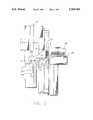
- FIG. 4is a side vertical section elevation view, certain parts being cut away for clarity, of the coaxial drive.
- FIGS. 5a and 5billustrate schematically the linkage of the transfer device.
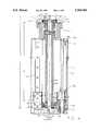
- FIG. 6is a side vertical section elevation view, certain parts being cut away for clarity, of the coaxial drive from an angle perpendicular to that shown in FIG. 4.
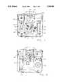
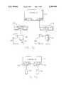
- FIG. 7is a bottom view of the elevator mechanism.
- FIG. 8is a top plan view of the elevator mechanism.
- FIG. 9is a side elevation view of a first embodiment of the theta drive coupling means as shown in FIG. 7.
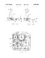
- FIG. 10is a partially fragmentary side elevation view of a second embodiment of theta drive coupling means.
- FIG. 11is a bottom view of the drive shown in FIG. 10.
- FIG. 12is a schematic of a control system usable with the invention.
- FIG. 13is a schematic of another control system usable with the invention.
- FIG. 1illustrates a series of processing systems 20 for operating on planar substrates which may include wafers and flat panels.
- the terms "wafer”, or “substrate”will be used for purposes of consistency to refer to such substrates, but it will be understood that it is intended to be used in the broad context so as to be applicable to all substrates.
- the processing systems 20may be arranged, for example, in side-by-side fashion within a "clean room" 22 separated from the outside environment by a wall 24. It may be possible to eliminate the clean room as a separate environment and, instead, maintain a desired clean environment within the system 20 and within each instrumentality which interfaces with the system.
- a transfer device 36which is positioned above the chamber base plate 31 and is articulated by a controller 10 to be described, a plurality of the substrates S in the cassette 26 or in the controlled environment box 26' are lifted off the shelves of the cassette or box and moved in stacked form into the chamber 30 of the load lock station 32 in one motion of the device 36. Subsequently, by means of a transport apparatus 37 disposed within a transport chamber 38 connected to the load lock 32, the substrates S are moved one by one to the transport chamber 38 and, from there, to one or more of a plurality of processing stations 40.
- the transfer device 36is mounted to the top of an elevator mechanism 44 for vertical movement along the indicated Z-axis.
- the elevator mechanism 44has a housing 43 and a mount 45 supported within the load lock 32 and controllably, selectively positions the device 36 at different height locations for the purpose of positioning each substrate S for engagement with the transport apparatus 37.
- the elevator mechanism 44includes a rotary shaft 56 which is disposed within a lift tube 54 responsible for moving the shaft 56 in the vertical direction along the Z-axis.
- a mounting block 51which is secured against movement to the tube 54 by an appropriate set of screws.
- the transfer device 36includes an articulated drive arm 60 pivotally connected to the mounting block 51 for rotation about the indicted axis AX.
- the free end 61 of the drive arm 60in turn supports a plurality 64 of end effectors 66 thereon which are arranged in a stacked arrangement and for rotational movement about the indicated axis MX.
- the drive arm 60 and the end effector plurality 64are moveable both angularly and linearly relative to the support arm 52 in order to move a stack of substrates S between the cassette support station and the chamber 30 of the load lock.
- the transport apparatus 37also includes substrate holders 33,33 which are controllably moved by instructions from the controller into and out of the load lock chambers 30,30 in order to pick up a substrate S supported on an end effector 66 within a chamber 30 and move it to one of the processing modules for processing and to thereafter place the worked on substrate back into the chamber where it is supported on one of the end effectors 66.
- the radius Rdefines the stroke length of the substrate holder 33 from the transport chamber center TC which is standard.
- Each substrate holder 33is complimentarily configured to mate with the shape of the end effectors 66 when moved along the radius R so as to lift a substrate S off the involved end effector when relative vertical movement therebetween is effected by the elevator mechanism 44.
- the end effectors 66in line with the radius R within the load lock 32, pick and place transport of the substrate S through relative vertical movement of the end effectors and the substrate holder can be achieved.
- the transfer device 36is capable of moving the center(s) C of the plurality of stacked substrates S (or even a single substrate) along a straight linear path as illustrated by the dashed line P extending between positions A-C in FIG. 3.
- the positions A and Care respectively associated with a cassette load and unload position (location A) and a transport chamber load and unload position (location B).
- the linear straight line Pidentifies the path followed by the substrate S as between the cassette 26 and the internal confines 30 of the locking station 32.
- the lift tube 54has a collar plate 59 secured to the upper end thereof through the intermediary of set screws 63.
- the mounting plate 51is secured to the end of the lift tube 54 through the intermediary of the collar plate which is connected to the mounting plate by screws 65.
- the mount 45connects to the chamber base plate 31 with threaded bolts 67 which are received within threaded openings formed in the bottom surface of the plate 31.
- the mount 45also includes a well 69 through which the lift tube passes. Connected to the collar plate 59 and to the bottom of the well 69, is a bellows seal 73 which is capable of axially expanding with the vertical movement of the lift tube to maintain a sealed environment within the chamber 30.
- An opening 68is formed in the base plate 31 and is of a diameter sufficient to permit passage of the bellows seal 73, or like device, and the coupled lift tube therethrough.
- a sliding cartridgemay be used and inserted within the well 69 in engagement with upper and lower lip seals.
- annular seal 77Surrounding the opening 68 in the base plate 31 radially outwardly thereof is an annular seal 77 which is received within an annular groove formed in the face of the mount 45 which confronts the undersurface of the base plate 31.
- the mounting block 51in the illustrated manner shown in FIG. 5 rotatably supports the drive arm 60 thereon for rotation about the indicted axis AX.
- the free end 61 of the drive arm 60in turn supports a plurality 64 of end effectors 66 thereon which are arranged in a stacked arrangement and for rotational movement about the indicated axis MX.
- the mounting block 51is stationary except for movement in the Z-axis.
- the drive arm 60 and the end effector plurality 64are however moveable both angularly and linearly relative to the block 51.
- Relative movement between the drive arm 60 and the end effector plurality 64, and between these elements taken relative to the mounting block 51is accomplished through the intermediary of an articulated linkage illustrated generally schematically at 70 in FIGS. 5a and 5b.
- One end of the linkageis secured to the drive arm 60 at point 71 and the other end of the linkage 70 is nonrotatably connected to the top end of the rotary shaft 56 at point 74.
- the articulated linkage 70is comprised of a minor arm 80 and a major arm 82 which are pivotally connected to one another at a pivot joint 86.
- the end of the minor arm 80which is associated with the rotary shaft 56 as illustrated in FIG.
- an elongated lead screw 92is provided in the elevator mechanism 44 and extends vertically parallel to the Z-axis between the upper and the lower ends of the housing or frame 43.
- the upper end of the lead screw 92is journalled for rotation within a horizontally extending portion 100 of the housing 43 and the lower end thereof is journalled for rotation within a brake assembly 102 secured to the housing 43.
- the lead screw 92is drivingly rotatably coupled to a Z-axis drive motor 100 (Seen in FIG. 7) which is secured against movement to the housing 43 and controllably rotates the lead screw in either rotational direction in response to commands issued by the controller 10.
- a drive belt 101is provided and engages around an output pulley 103 mounted on the motor 100 and a driven pulley 105 which is nonrotatably coupled to the lower end of the lead screw 92.
- Disposed for movement on the lead screw 92is a lift carriage 104 which is threadedly coupled to the lead screw 92 by a drive nut 106 secured to the lift carriage so that rotation of the lead screw in either direction causes a corresponding upward or downward movement of the lift carriage 104.
- the lift carriagehas a support base 108 defining a support surface 112 thereon which extends perpendicularly to the longitudinal extent of the lead screw 92.
- the lower end 114 of the lift tube 56is supported on the support surface 112 and is secured against movement thereupon by a locking screw 116 such that the lift tube moves upwards or downwards in unity with the carriage 104 in response to the energization or reverse energization of the drive motor 100.
- the support basehas an opening 120 formed therein with a diameter D1 which is smaller than the outer diameter D2 of the lift tube, but is of a diameter somewhat larger than the diameter D3 of the rotary shaft 56.
- the rotary shaft 54has a length L1 which is greater than the length L2 of the lift tube 56 so that a portion of the rotary shaft 56 extends upwards beyond the lift tube to provide a surface onto which the clamping collar 88 of the linkage 70 connects.
- the relative lengthsare such that the lower end of the rotary shaft 54 also extends downwards beyond the lower end of the lift tube 56 and into and through the opening 120 in the support base 108,
- the length of the shaft 54 which depends beyond the support base 108defines a connecting length 122 which has an annular locating member 124 clamped against axial movement to the support base 108 of the lift carriage 104 by an end plate 126.
- Race bearings 128are provided and are disposed within the support base 108 to rotatably journal the lower end of the rotary shaft 56 therewithin.
- the carriage 104includes an integrally formed cantilevered plate portion 130 onto which is mounted a theta drive motor 132 having an output shaft 134 which extends parallel to the Z axis and is spaced therefrom in a side by side arrangement.
- a coupling means 136is provided between the lowermost connecting length 122 of the output shaft 134 and the theta drive motor 132 to effect controlled rotation of the shaft 56.
- the coupling meanscan take various different forms, but for the moment it should be understood that the means 136 translates either rotary or linear movement from the theta drive motor 132 to rotate the rotary shaft 56.
- the means 140includes a way 142 which is secured within the housing 43 and extends parallel to the Z axis.
- a slide 144is secured to the carriage 104 and slidingly moves along the way in a conventional manner as is known in the art.
- the Z-axis and theta drive motorsare connected to a power supply (not shown) through the intermediary of a coiled power cord 146 depending from the top of the housing 43.
- a vacuum line 148which has one end connected to an external differential pump.
- the other end of the line 148is connected to a passage (not shown) communicating with the internal confines of the lift tube 54 to evacuate air therefrom.
- a branch of the vacuum line 148may further be connected to a duct 149 located in the collar plate 59 of the lift tube 56 and communicating with the internal confines of the lift tube.
- the coupling means 136may take many different forms. As illustrated in FIGS. 7 and 9, in a first form, the coupling means 136 includes a three-piece linkage 150 having a first link piece 152 nonrotatably connected to a rotary output shaft 134 of the theta drive motor 132, and a second linkage piece 156 having one end nonrotatably connected to the depending end length 122 of the rotary shaft 56 and another end pivotally connected to a third link piece 158 whose other end pivotally connects to the free end of the second linkage piece 156. In this way, rotary movement CC of the output shaft 154 causes a resultant rotation CC of the rotary shaft 56 and vice versa.
- the coupling means 136may take the form of a drive belt 162 which is trained about a drive pulley associated with the theta drive 132 and a driven pulley 166 associated with the rotary shaft 56.
- each of the Z-axis and theta motors 100 and 132is a servo motor which employs a servo drive feedback loop 166 connected with the controller 10 to position the moved elements angularly and vertically without hands on control of the motors 100 and 132 by the controller 10.
- sensors 170are provided on the housing and sense the vertical position of the lift carriage 104 while angular position sensors 172 are provided to sense the angular position of the rotary shaft 54 and each is connected to an its associated feedback loop 166.
- the carriage 104carries subcontroller panels 174 and 176 for each of the loops.
- the drive motors 100 and 132 usedmay be stepper motors, and driven by commands directly from the controller 10 from drivers 180 and 182 in an open loop type system.
- theta drive motor 132may take the form of the pneumatic actuator having a sliding piston moveable between first and second positions which can be directly linked to a bell crank on the lower end of the rotary shaft 56. In such an arrangement, it would be advantageous to employ an open loop control system to effect the ON and OFF controls of the drive motor. Additionally, the coaxial drive may be usable in other applications, not necessarily limited to substrate handling.
Landscapes
- Engineering & Computer Science (AREA)
- Power Engineering (AREA)
- Microelectronics & Electronic Packaging (AREA)
- Condensed Matter Physics & Semiconductors (AREA)
- General Physics & Mathematics (AREA)
- Manufacturing & Machinery (AREA)
- Computer Hardware Design (AREA)
- Physics & Mathematics (AREA)
- Structural Engineering (AREA)
- Mechanical Engineering (AREA)
- Automation & Control Theory (AREA)
- Robotics (AREA)
- Container, Conveyance, Adherence, Positioning, Of Wafer (AREA)
- Warehouses Or Storage Devices (AREA)
- Manipulator (AREA)
- Transmission Devices (AREA)
Abstract
Description
Claims (19)
Priority Applications (7)
| Application Number | Priority Date | Filing Date | Title |
|---|---|---|---|
| US08/722,353US5769184A (en) | 1996-09-27 | 1996-09-27 | Coaxial drive elevator |
| JP10515633AJP2001501038A (en) | 1996-09-27 | 1997-08-29 | Coaxial drive elevator |
| PCT/US1997/014167WO1998013289A1 (en) | 1996-09-27 | 1997-08-29 | Coaxial drive elevator |
| KR1019990702634AKR20000048686A (en) | 1996-09-27 | 1997-08-29 | Coaxial drive elevator |
| AU42304/97AAU4230497A (en) | 1996-09-27 | 1997-08-29 | Coaxial drive elevator |
| EP97940553AEP0958226A4 (en) | 1996-09-27 | 1997-08-29 | Coaxial drive elevator |
| TW086112738ATW384273B (en) | 1996-09-27 | 1997-09-04 | An elevator mechanism and a rotary linear drive |
Applications Claiming Priority (1)
| Application Number | Priority Date | Filing Date | Title |
|---|---|---|---|
| US08/722,353US5769184A (en) | 1996-09-27 | 1996-09-27 | Coaxial drive elevator |
Publications (1)
| Publication Number | Publication Date |
|---|---|
| US5769184Atrue US5769184A (en) | 1998-06-23 |
Family
ID=24901503
Family Applications (1)
| Application Number | Title | Priority Date | Filing Date |
|---|---|---|---|
| US08/722,353Expired - LifetimeUS5769184A (en) | 1996-09-27 | 1996-09-27 | Coaxial drive elevator |
Country Status (7)
| Country | Link |
|---|---|
| US (1) | US5769184A (en) |
| EP (1) | EP0958226A4 (en) |
| JP (1) | JP2001501038A (en) |
| KR (1) | KR20000048686A (en) |
| AU (1) | AU4230497A (en) |
| TW (1) | TW384273B (en) |
| WO (1) | WO1998013289A1 (en) |
Cited By (3)
| Publication number | Priority date | Publication date | Assignee | Title |
|---|---|---|---|---|
| US6290448B1 (en)* | 1998-04-07 | 2001-09-18 | Focke & Co. (Gmbh & Co.) | Lifting device (pallet device) with pivotal arm |
| US6551044B1 (en) | 1999-09-14 | 2003-04-22 | Asm America, Inc. | Bellows isolation for index platforms |
| US20040255442A1 (en)* | 2003-06-19 | 2004-12-23 | Mcdiarmid James | Methods and apparatus for processing workpieces |
Families Citing this family (1)
| Publication number | Priority date | Publication date | Assignee | Title |
|---|---|---|---|---|
| US4701427A (en)* | 1985-10-17 | 1987-10-20 | Stemcor Corporation | Sintered silicon carbide ceramic body of high electrical resistivity |
Citations (35)
| Publication number | Priority date | Publication date | Assignee | Title |
|---|---|---|---|---|
| US2333341A (en)* | 1942-03-03 | 1943-11-02 | Scrivener Arthur | Tool slide adjusting means |
| US3803927A (en)* | 1972-07-10 | 1974-04-16 | Bridgeport Machines | Coaxial force and movement mechanism for a machine tool |
| US3805629A (en)* | 1972-06-01 | 1974-04-23 | Usm Corp | Devices for linear and rotational movements |
| US4466769A (en)* | 1981-06-29 | 1984-08-21 | Fujitsu Fanuc Limited | Industrial robot |
| JPS6073163A (en)* | 1983-09-30 | 1985-04-25 | Fujitsu Ltd | Screw shaft structure |
| US4614128A (en)* | 1981-12-18 | 1986-09-30 | Lars International S.A., Luxembourg | Linear drive device with two motors |
| US4643629A (en)* | 1984-10-30 | 1987-02-17 | Anelva Corporation | Automatic loader |
| US4682930A (en)* | 1985-06-05 | 1987-07-28 | Ichikoh Engineering, Ltd. | Apparatus for upward and downward movement of an arm in a robot system for taking out injection molded and die casting products |
| US4687542A (en)* | 1985-10-24 | 1987-08-18 | Texas Instruments Incorporated | Vacuum processing system |
| US4712441A (en)* | 1985-05-13 | 1987-12-15 | Brunswick Valve & Control, Inc. | Position controlled linear actuator |
| US4719810A (en)* | 1986-05-15 | 1988-01-19 | Usm Corporation | Drive mechanism for electrical component placement head |
| US4739669A (en)* | 1984-12-17 | 1988-04-26 | Seiko Instruments & Electronics Ltd. | Driving apparatus for industrial robot |
| US4764076A (en)* | 1986-04-17 | 1988-08-16 | Varian Associates, Inc. | Valve incorporating wafer handling arm |
| US4781511A (en)* | 1986-03-25 | 1988-11-01 | Shimizu Construction Co., Ltd. | Semiconductor processing system |
| US4782713A (en)* | 1985-09-10 | 1988-11-08 | Fanuc Ltd | Industrial robot shaft supporting mechanism |
| US4829840A (en)* | 1985-09-11 | 1989-05-16 | Fanuc Ltd. | Industrial robot with replaceable module |
| US4858481A (en)* | 1985-05-13 | 1989-08-22 | Brunswick Valve & Control, Inc. | Position controlled linear actuator |
| US4911597A (en)* | 1985-01-22 | 1990-03-27 | Applied Materials, Inc. | Semiconductor processing system with robotic autoloader and load lock |
| JPH02113152A (en)* | 1988-10-19 | 1990-04-25 | Tsubakimoto Seiko:Kk | Compound structure of ball spline and ball screw |
| US4981408A (en)* | 1989-12-18 | 1991-01-01 | Varian Associates, Inc. | Dual track handling and processing system |
| US5069269A (en)* | 1989-01-23 | 1991-12-03 | Leybold Aktiengesellschaft | Lifting and turning unit for a melting and/or casting plant |
| US5111708A (en)* | 1989-03-09 | 1992-05-12 | R.G.B. S.P.A. | Electromechanical linear actuator |
| US5111709A (en)* | 1989-09-27 | 1992-05-12 | Fanuc, Ltd. | Industrial robot with a telescopic horizontal arm |
| US5117701A (en)* | 1989-11-14 | 1992-06-02 | Gec Alsthom Sa | Screw-and nut type member for transmitting rotary motion |
| US5128688A (en)* | 1990-11-27 | 1992-07-07 | Sperry Marine, Inc. | Mast translation and rotation drive system utilizing a ball drive screw and nut assembly |
| US5148714A (en)* | 1990-10-24 | 1992-09-22 | Ag Processing Technology, Inc. | Rotary/linear actuator for closed chamber, and reaction chamber utilizing same |
| US5223001A (en)* | 1991-11-21 | 1993-06-29 | Tokyo Electron Kabushiki Kaisha | Vacuum processing apparatus |
| US5224809A (en)* | 1985-01-22 | 1993-07-06 | Applied Materials, Inc. | Semiconductor processing system with robotic autoloader and load lock |
| US5234303A (en)* | 1990-05-15 | 1993-08-10 | Seiko Instruments Inc. | In-vacuum conveyance robot |
| US5251500A (en)* | 1990-09-27 | 1993-10-12 | Fanuc Ltd. | Industrial robot with a compound drive mechanism |
| US5271702A (en)* | 1992-02-03 | 1993-12-21 | Environmental Research Institute Of Michigan | Robotic substrate manipulator |
| US5327795A (en)* | 1992-01-07 | 1994-07-12 | Nsk Ltd. | Ball screw apparatus |
| US5346045A (en)* | 1992-01-09 | 1994-09-13 | Link-Miles Limited | Electrically powered actuator |
| DE4316423A1 (en)* | 1993-05-17 | 1994-11-24 | Josef Dipl Ing Baeumer | Transmission with a rectilinear output, particularly for a press |
| US5540821A (en)* | 1993-07-16 | 1996-07-30 | Applied Materials, Inc. | Method and apparatus for adjustment of spacing between wafer and PVD target during semiconductor processing |
Family Cites Families (3)
| Publication number | Priority date | Publication date | Assignee | Title |
|---|---|---|---|---|
| JPS61184841A (en)* | 1985-02-13 | 1986-08-18 | Canon Inc | Wafer positioning method and device |
| US4770590A (en)* | 1986-05-16 | 1988-09-13 | Silicon Valley Group, Inc. | Method and apparatus for transferring wafers between cassettes and a boat |
| US4952299A (en)* | 1988-10-31 | 1990-08-28 | Eaton Corporation | Wafer handling apparatus |
- 1996
- 1996-09-27USUS08/722,353patent/US5769184A/ennot_activeExpired - Lifetime
- 1997
- 1997-08-29AUAU42304/97Apatent/AU4230497A/ennot_activeAbandoned
- 1997-08-29WOPCT/US1997/014167patent/WO1998013289A1/ennot_activeApplication Discontinuation
- 1997-08-29KRKR1019990702634Apatent/KR20000048686A/ennot_activeAbandoned
- 1997-08-29JPJP10515633Apatent/JP2001501038A/enactivePending
- 1997-08-29EPEP97940553Apatent/EP0958226A4/ennot_activeWithdrawn
- 1997-09-04TWTW086112738Apatent/TW384273B/ennot_activeIP Right Cessation
Patent Citations (35)
| Publication number | Priority date | Publication date | Assignee | Title |
|---|---|---|---|---|
| US2333341A (en)* | 1942-03-03 | 1943-11-02 | Scrivener Arthur | Tool slide adjusting means |
| US3805629A (en)* | 1972-06-01 | 1974-04-23 | Usm Corp | Devices for linear and rotational movements |
| US3803927A (en)* | 1972-07-10 | 1974-04-16 | Bridgeport Machines | Coaxial force and movement mechanism for a machine tool |
| US4466769A (en)* | 1981-06-29 | 1984-08-21 | Fujitsu Fanuc Limited | Industrial robot |
| US4614128A (en)* | 1981-12-18 | 1986-09-30 | Lars International S.A., Luxembourg | Linear drive device with two motors |
| JPS6073163A (en)* | 1983-09-30 | 1985-04-25 | Fujitsu Ltd | Screw shaft structure |
| US4643629A (en)* | 1984-10-30 | 1987-02-17 | Anelva Corporation | Automatic loader |
| US4739669A (en)* | 1984-12-17 | 1988-04-26 | Seiko Instruments & Electronics Ltd. | Driving apparatus for industrial robot |
| US5224809A (en)* | 1985-01-22 | 1993-07-06 | Applied Materials, Inc. | Semiconductor processing system with robotic autoloader and load lock |
| US4911597A (en)* | 1985-01-22 | 1990-03-27 | Applied Materials, Inc. | Semiconductor processing system with robotic autoloader and load lock |
| US4712441A (en)* | 1985-05-13 | 1987-12-15 | Brunswick Valve & Control, Inc. | Position controlled linear actuator |
| US4858481A (en)* | 1985-05-13 | 1989-08-22 | Brunswick Valve & Control, Inc. | Position controlled linear actuator |
| US4682930A (en)* | 1985-06-05 | 1987-07-28 | Ichikoh Engineering, Ltd. | Apparatus for upward and downward movement of an arm in a robot system for taking out injection molded and die casting products |
| US4782713A (en)* | 1985-09-10 | 1988-11-08 | Fanuc Ltd | Industrial robot shaft supporting mechanism |
| US4829840A (en)* | 1985-09-11 | 1989-05-16 | Fanuc Ltd. | Industrial robot with replaceable module |
| US4687542A (en)* | 1985-10-24 | 1987-08-18 | Texas Instruments Incorporated | Vacuum processing system |
| US4781511A (en)* | 1986-03-25 | 1988-11-01 | Shimizu Construction Co., Ltd. | Semiconductor processing system |
| US4764076A (en)* | 1986-04-17 | 1988-08-16 | Varian Associates, Inc. | Valve incorporating wafer handling arm |
| US4719810A (en)* | 1986-05-15 | 1988-01-19 | Usm Corporation | Drive mechanism for electrical component placement head |
| JPH02113152A (en)* | 1988-10-19 | 1990-04-25 | Tsubakimoto Seiko:Kk | Compound structure of ball spline and ball screw |
| US5069269A (en)* | 1989-01-23 | 1991-12-03 | Leybold Aktiengesellschaft | Lifting and turning unit for a melting and/or casting plant |
| US5111708A (en)* | 1989-03-09 | 1992-05-12 | R.G.B. S.P.A. | Electromechanical linear actuator |
| US5111709A (en)* | 1989-09-27 | 1992-05-12 | Fanuc, Ltd. | Industrial robot with a telescopic horizontal arm |
| US5117701A (en)* | 1989-11-14 | 1992-06-02 | Gec Alsthom Sa | Screw-and nut type member for transmitting rotary motion |
| US4981408A (en)* | 1989-12-18 | 1991-01-01 | Varian Associates, Inc. | Dual track handling and processing system |
| US5234303A (en)* | 1990-05-15 | 1993-08-10 | Seiko Instruments Inc. | In-vacuum conveyance robot |
| US5251500A (en)* | 1990-09-27 | 1993-10-12 | Fanuc Ltd. | Industrial robot with a compound drive mechanism |
| US5148714A (en)* | 1990-10-24 | 1992-09-22 | Ag Processing Technology, Inc. | Rotary/linear actuator for closed chamber, and reaction chamber utilizing same |
| US5128688A (en)* | 1990-11-27 | 1992-07-07 | Sperry Marine, Inc. | Mast translation and rotation drive system utilizing a ball drive screw and nut assembly |
| US5223001A (en)* | 1991-11-21 | 1993-06-29 | Tokyo Electron Kabushiki Kaisha | Vacuum processing apparatus |
| US5327795A (en)* | 1992-01-07 | 1994-07-12 | Nsk Ltd. | Ball screw apparatus |
| US5346045A (en)* | 1992-01-09 | 1994-09-13 | Link-Miles Limited | Electrically powered actuator |
| US5271702A (en)* | 1992-02-03 | 1993-12-21 | Environmental Research Institute Of Michigan | Robotic substrate manipulator |
| DE4316423A1 (en)* | 1993-05-17 | 1994-11-24 | Josef Dipl Ing Baeumer | Transmission with a rectilinear output, particularly for a press |
| US5540821A (en)* | 1993-07-16 | 1996-07-30 | Applied Materials, Inc. | Method and apparatus for adjustment of spacing between wafer and PVD target during semiconductor processing |
Cited By (3)
| Publication number | Priority date | Publication date | Assignee | Title |
|---|---|---|---|---|
| US6290448B1 (en)* | 1998-04-07 | 2001-09-18 | Focke & Co. (Gmbh & Co.) | Lifting device (pallet device) with pivotal arm |
| US6551044B1 (en) | 1999-09-14 | 2003-04-22 | Asm America, Inc. | Bellows isolation for index platforms |
| US20040255442A1 (en)* | 2003-06-19 | 2004-12-23 | Mcdiarmid James | Methods and apparatus for processing workpieces |
Also Published As
| Publication number | Publication date |
|---|---|
| KR20000048686A (en) | 2000-07-25 |
| EP0958226A1 (en) | 1999-11-24 |
| AU4230497A (en) | 1998-04-17 |
| JP2001501038A (en) | 2001-01-23 |
| EP0958226A4 (en) | 2005-08-10 |
| WO1998013289A1 (en) | 1998-04-02 |
| TW384273B (en) | 2000-03-11 |
Similar Documents
| Publication | Publication Date | Title |
|---|---|---|
| US5954472A (en) | Batch loader arm | |
| US20240066685A1 (en) | Substrate transport apparatus with multiple movable arms utilizing a mechanical switch mechanism | |
| US12263587B2 (en) | Dual arm robot | |
| US11801598B2 (en) | Substrate transport apparatus with multiple movable arms utilizing a mechanical switch mechanism | |
| US7419346B2 (en) | Integrated system for tool front-end workpiece handling | |
| US5224809A (en) | Semiconductor processing system with robotic autoloader and load lock | |
| US20060263187A1 (en) | Method and apparatus for unloading substrate carriers from substrate carrier transport system | |
| KR20010023014A (en) | Wafer handler for multi-station tool | |
| JPH0828411B2 (en) | Semiconductor wafer manufacturing apparatus, semiconductor wafer processing apparatus and chuck apparatus | |
| KR102394121B1 (en) | Travel robot for driving substrate transfer robot in chamber | |
| US6481951B1 (en) | Multiple sided robot blade for semiconductor processing equipment | |
| US5997235A (en) | Swap out plate and assembly | |
| JP2010524201A5 (en) | ||
| JPH0763612B2 (en) | Vacuum chamber and method of transporting processed material in vacuum chamber | |
| JP2004090186A (en) | Clean transfer robot | |
| US5769184A (en) | Coaxial drive elevator | |
| JP2003516622A (en) | Front-end loader transporter with small installation area | |
| JPH07171778A (en) | Articulated conveyor device, control method thereof and semiconductor manufacturing device | |
| US5908281A (en) | Coaxial drive loader arm | |
| KR20070015945A (en) | Goods processing method and apparatus | |
| JP2004146714A (en) | Carrying mechanism for workpiece | |
| US20020146303A1 (en) | Wafer handling system and apparatus | |
| KR20210119185A (en) | Transfer Robot and Substrate Processing apparatus having the same | |
| JP2958587B2 (en) | Directional transfer device for semiconductor | |
| JPH04267355A (en) | Wafer conveying robot |
Legal Events
| Date | Code | Title | Description |
|---|---|---|---|
| AS | Assignment | Owner name:BROOKS AUTOMATION, MASSACHUSETTS Free format text:ASSIGNMENT OF ASSIGNORS INTEREST;ASSIGNOR:HOFMEISTER, CHRISTOPHER A.;REEL/FRAME:008386/0678 Effective date:19970114 | |
| STCF | Information on status: patent grant | Free format text:PATENTED CASE | |
| FEPP | Fee payment procedure | Free format text:PAYOR NUMBER ASSIGNED (ORIGINAL EVENT CODE: ASPN); ENTITY STATUS OF PATENT OWNER: LARGE ENTITY | |
| FEPP | Fee payment procedure | Free format text:PAT HOLDER NO LONGER CLAIMS SMALL ENTITY STATUS, ENTITY STATUS SET TO UNDISCOUNTED (ORIGINAL EVENT CODE: STOL); ENTITY STATUS OF PATENT OWNER: LARGE ENTITY | |
| FPAY | Fee payment | Year of fee payment:4 | |
| REMI | Maintenance fee reminder mailed | ||
| FEPP | Fee payment procedure | Free format text:ENTITY STATUS SET TO UNDISCOUNTED (ORIGINAL EVENT CODE: BIG.); ENTITY STATUS OF PATENT OWNER: LARGE ENTITY | |
| FPAY | Fee payment | Year of fee payment:8 | |
| FEPP | Fee payment procedure | Free format text:PAYER NUMBER DE-ASSIGNED (ORIGINAL EVENT CODE: RMPN); ENTITY STATUS OF PATENT OWNER: LARGE ENTITY Free format text:PAYOR NUMBER ASSIGNED (ORIGINAL EVENT CODE: ASPN); ENTITY STATUS OF PATENT OWNER: LARGE ENTITY | |
| FPAY | Fee payment | Year of fee payment:12 | |
| SULP | Surcharge for late payment | Year of fee payment:11 | |
| AS | Assignment | Owner name:WELLS FARGO BANK, NATIONAL ASSOCIATION, MASSACHUSETTS Free format text:SECURITY AGREEMENT;ASSIGNORS:BROOKS AUTOMATION, INC.;BIOSTORAGE TECHNOLOGIES;REEL/FRAME:038891/0765 Effective date:20160526 Owner name:WELLS FARGO BANK, NATIONAL ASSOCIATION, MASSACHUSE Free format text:SECURITY AGREEMENT;ASSIGNORS:BROOKS AUTOMATION, INC.;BIOSTORAGE TECHNOLOGIES;REEL/FRAME:038891/0765 Effective date:20160526 | |
| AS | Assignment | Owner name:MORGAN STANLEY SENIOR FUNDING, INC., MARYLAND Free format text:SECURITY INTEREST;ASSIGNORS:BROOKS AUTOMATION, INC.;BIOSTORAGE TECHNOLOGIES, INC.;REEL/FRAME:044142/0258 Effective date:20171004 |