US5767960A - Optical 6D measurement system with three fan-shaped beams rotating around one axis - Google Patents
Optical 6D measurement system with three fan-shaped beams rotating around one axisDownload PDFInfo
- Publication number
- US5767960A US5767960AUS08/663,987US66398796AUS5767960AUS 5767960 AUS5767960 AUS 5767960AUS 66398796 AUS66398796 AUS 66398796AUS 5767960 AUS5767960 AUS 5767960A
- Authority
- US
- United States
- Prior art keywords
- beams
- light
- receiver
- orientation
- sensors
- Prior art date
- Legal status (The legal status is an assumption and is not a legal conclusion. Google has not performed a legal analysis and makes no representation as to the accuracy of the status listed.)
- Expired - Lifetime
Links
- 230000003287optical effectEffects0.000titleabstractdescription34
- 238000005259measurementMethods0.000titledescription17
- 238000000034methodMethods0.000claimsabstractdescription13
- 238000012545processingMethods0.000claimsdescription13
- 230000000630rising effectEffects0.000claimsdescription7
- 238000004364calculation methodMethods0.000abstractdescription8
- 238000010586diagramMethods0.000description11
- 239000013598vectorSubstances0.000description4
- 230000007246mechanismEffects0.000description2
- 230000005855radiationEffects0.000description2
- 238000010561standard procedureMethods0.000description2
- 230000004075alterationEffects0.000description1
- 230000003321amplificationEffects0.000description1
- 238000013459approachMethods0.000description1
- 230000033228biological regulationEffects0.000description1
- 238000004422calculation algorithmMethods0.000description1
- 238000001444catalytic combustion detectionMethods0.000description1
- 239000004020conductorSubstances0.000description1
- 230000007423decreaseEffects0.000description1
- 238000011161developmentMethods0.000description1
- 238000006073displacement reactionMethods0.000description1
- 239000003814drugSubstances0.000description1
- 238000001914filtrationMethods0.000description1
- 239000011521glassSubstances0.000description1
- 239000011159matrix materialSubstances0.000description1
- 238000000691measurement methodMethods0.000description1
- 238000012986modificationMethods0.000description1
- 230000004048modificationEffects0.000description1
- 238000003199nucleic acid amplification methodMethods0.000description1
- 230000008569processEffects0.000description1
- 238000001228spectrumMethods0.000description1
- 230000002123temporal effectEffects0.000description1
- 230000007704transitionEffects0.000description1
- 238000013519translationMethods0.000description1
Images


Classifications
- G—PHYSICS
- G01—MEASURING; TESTING
- G01B—MEASURING LENGTH, THICKNESS OR SIMILAR LINEAR DIMENSIONS; MEASURING ANGLES; MEASURING AREAS; MEASURING IRREGULARITIES OF SURFACES OR CONTOURS
- G01B11/00—Measuring arrangements characterised by the use of optical techniques
- G01B11/26—Measuring arrangements characterised by the use of optical techniques for measuring angles or tapers; for testing the alignment of axes
- G—PHYSICS
- G01—MEASURING; TESTING
- G01B—MEASURING LENGTH, THICKNESS OR SIMILAR LINEAR DIMENSIONS; MEASURING ANGLES; MEASURING AREAS; MEASURING IRREGULARITIES OF SURFACES OR CONTOURS
- G01B11/00—Measuring arrangements characterised by the use of optical techniques
- G01B11/002—Measuring arrangements characterised by the use of optical techniques for measuring two or more coordinates
Definitions
- This inventionrelates to the determination of the six spatial parameters position (x, y, z) and orientation ( ⁇ , ⁇ , ⁇ ) of an object relative to a fixed reference point.
- the inventionhas applications in the fields of medicine, robotics, fire control systems, remote control applications, and virtual reality systems.
- the deviceis designed for measuring position and orientation in six degrees of freedom, namely motion or translation in three coordinate directions (location), and rotational motion about three coordinate axes (orientation), location being commonly defined as a set of x, y, and z linear coordinates referring to three mutually perpendicular directions (axes) and orientation being commonly defined as pitch, roll and azimuth angular coordinates about three mutually perpendicular axes usually coincident with three mutually perpendicular directions.
- locationbeing commonly defined as a set of x, y, and z linear coordinates referring to three mutually perpendicular directions (axes) and orientation being commonly defined as pitch, roll and azimuth angular coordinates about three mutually perpendicular axes usually coincident with three mutually perpendicular directions.
- Prior art spatial position and orientation measurement equipmentrely on either optical or electromagnetic techniques to determine spatial coordinates.
- the optical schemesoften rely on a complex scheme of multiple scanners, in conjunction with reflectors and photosensors to function properly.
- U.S. Pat. No. 3,375,375 to Abbey et al.discloses the use of two rotating scanners generating optical fan shaped beams as well as sensors attached to the object to be measured, specifically a pilot's helmet. This two scanner system is necessary merely to compute the line-of-sight (LOS) to the pilot's helmet, and offers no method to determine the position or orientation of the pilot's helmet.
- LOSline-of-sight
- U.S. Pat. No. 4,818,107 to Ono et al.discloses a system for measuring the position of a moving body.
- the systemutilizes two fixed scanning laser beams with separate origins and three photodetectors on the moving body.
- the systemuses triangulation and measures only the position (x,y,z) and the attitude angle but fails to measure both the position and orientation in six dimensions.
- U.S. Pat. No. 4,896,962 to Menn et al.discloses a system for determining the spatial location and the line-of-sight of a person wearing a helmet.
- the systemutilizes at least four LEDs placed on the helmet and a fixed two-dimensional array of photoelectric elements.
- a spherical lensis placed in front of the detector in order to focus the light from the LEDs onto the detector.
- the work area of this systemis limited to the coverage of the lens.
- the present inventionhas a 360 degree work area due to the rotation of the beams.
- the present inventionutilizes rotary fan-shaped light beams and movable photo detectors.
- the present inventionutilizes time measurements and overcomes problems with ambient light sources and positional errors with CCDs in order to achieve higher accuracies.
- U.S. Pat. No. 4,911,548 to Keren-Gilldiscloses a system that employs multiple scanners for the origination of multiple fan-shaped optical beams.
- the scanning mechanismis extremely complicated and cumbersome, and requires precise synchronization between the scanners in order to maintain measurement accuracy.
- the Keren-Gill systemdoes not measure the six position and orientation coordinates measured by the present invention.
- U.S. Pat. No. 5,128,794 to Mocker et al.discloses a system for measuring the helmet mounted sight of a pilot.
- the systemutilizes at least two laser scanning units with different origin.
- the systemutilizes at least two motors and further utilizes passive reflective markers on the pilot.
- Mocker et al.only measure the pilot's line-of-sight and do not measure both the position and orientation in six dimensions.
- U.S. Pat. 5,208,641 to Mocker et al.discloses a system for also measuring the helmet mounted sight of a pilot.
- the systemutilizes a laser cavity and at least three laser detectors.
- the systemfurther utilizes passive reflective markers on the pilot but only measures the pilot's line-of-sight and not the position and orientation in six dimensions.
- Prior optical systemsare also subject to interference from extraneous sources such as ambient light or electrical sources and, as such, are prone to error, or, at minimum, severe limitations in system flexibility and ease of operation.
- the inventionis based on the simple premise that if the angular velocity, of the optical beams is known, then the angle, that is swept in a time interval t is calculated by the relationship given in Equation 1.
- the present inventionincludes a technique for the determination of the distance and orientation of an object from a fixed reference point when the object is irradiated by three modulated scanning beams of known angular orientation, and rotational frequency, ⁇ .
- Timing circuitry located in the control processordetermines the time interval .increment.t , between successive interceptions of the object by each of the three beams. Knowledge of this time interval and the scanning beams' relative positions and angular orientations permits calculation of the object's spatial coordinates.
- the optical beams utilized in this inventionare fan-shaped in cross-section. Use of the fan-shaped beams, rather than narrowly focused beams, facilitates angular measurements made outside the plane of the transmitter.
- the measurement accuracy of the deviceis a direct function of the stability of the scanning transmitter and the accuracy that the timing intervals can be measured.
- This inventionemploys techniques to ensure transmitter scanning stability, as well as unique timing measurement techniques to achieve accurate spatial coordinate measurements.
- the systememploys a receiver located at the object whose position is to be measured relative to the scanning transmitter.
- the receivermakes use of optically sensitive devices which respond to the radiation spectrum of the transmitted beams.
- the optical devicesgenerate a voltage signal proportional to the incident optical energy, which is amplified and manipulated by the control processor to accurately determine the precise time that an optical beam impinged on a particular sensor. Knowledge of the precise time interval is then used to calculate the angle through the fundamental relationship as given in Equation 1.
- the scanning transmittergenerates three modulated optical beams, two of which are parallel and separated from each other by a known distance, while the third beam is skewed at an angle of relative to the other two beams. Spatial and hence temporal synchronism between the beams is inherent in the scanning transmitter mechanism due to the fact that all three beams are generated simultaneously by a single scan generator, with a common point of origin. Use of a single transmitter obviates potential problems inherent with other proposed inventions that rely on an individual scanner for the generation of each beam, and, as such, have stringent system requirements on the positional stability, frequency and phase synchronization between the scanners.
- FIG. 1shows a schematic representation of a first embodiment of the present invention wherein the receiver sensor assembly is scanned by the scanning transmitter with coordinate system and pitch, roll and yaw definitions for the sensor plane defined.
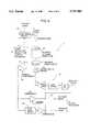
- FIG. 2shows a block diagram of the three axis optical measurement system of FIG. 1, showing all major component parts.
- FIG. 3shows a schematic diagram of the elements of the receiver sensor assembly thereof.
- FIG. 4shows the component parts of the scanning transmitter assembly thereof.
- FIG. 5shows a diagram of the preferred optical assembly of the scanner thereof, depicting the pyramid beam splitter, two mirrors and three thin glass rod lenses designed to split the incoming IR energy generated by the laser diode to form the three fan-shaped IR beams.
- FIG. 6shows a schematic block diagram of the control processor thereof.
- FIG. 7shows a timing diagram thereof depicting the modulated optical signal seen at the output of the PIN diode sensor assembly, the demodulated, low-pass filtered signal, comparator output and the timing measurements used to determine the precise point that the modulated optical beam intercepts the center of a particular optical sensor.
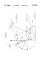
- FIG. 8shows the geometry of the system of FIG. 1 with the scanner and its three optical beam patterns, and the receiver assembly with its three sensors.
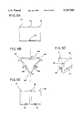
- FIGS. 9A, 9B, 9C, and 9Dshow front, top, rear, and perspective views, respectively, of an alternative receiver assembly with six sensors.
- FIG. 10shows the geometry for determination of the spatial coordinates (x,y).
- FIG. 11shows the geometry for determination of the z coordinate with the skew plane generated by the three axis system.
- FIG. 12shows the geometry for determination of receiver orientation.
- the inventive systemis generally designated by the reference numeral 10 and the geometry of the optical system is depicted.
- the transmitter means or scanning transmitter 11emits three fan-shaped beams 1, 2 and 3. Beam 1 and beam 2 lie in parallel planes tangent to rotating cylinder 13. Beam 3 is skewed in relation to beam 1 and beam 2 at the angle ⁇ but is also placed on the rotating cylinder.
- the receiver or receiver assembly 19consists of at least three sensors S1, S2 and S3 arranged in a triangular pattern as shown. The system 10 measures the position of each of the sensors and then calculates the receiver assembly position and orientation.
- FIG. 2shows, schematically, a block diagram of the three axis measurement system that is the basis of this invention.
- the principal component parts of the systemare the scanning transmitter 11, the receiver sensor assembly 19, and the computer means or control processor 20.
- the processor 20supplies synchronization timing, laser diode modulation, and DC voltages to the scanning transmitter 11.
- the control processor 20also generates a low noise DC bias voltage that powers the receiver sensor assembly 19, and receives, via the connection means shown, the three optical sensor outputs generated by the receiver 19.
- the control processor 20performs all signal processing and coordinate determination to the host computer or microprocessor 23.
- FIG. 3shows, schematically, a block diagram of the receiver sensor assembly.
- the receiver sensorconsists of three PIN photodiodes 25, 27 and 29 arranged in a triangular pattern, mounted on a circuit card assembly.
- the photodiodesare also denoted as S1, S2, and S3 in the diagram given in FIG. 3.
- the PIN diodesserve to sense the modulated infrared (IR) energy generated by the scanning transmitter 11.
- Each diodeis connected in reverse-bias mode to a low noise amplifier 31.
- Each amplifier's outputis connected through a cable to the control processor unit for further amplification and signal processing.
- Amplifier and PIN diode bias voltagesare connected to the receiver through the same cable. These bias voltages are derived from a separate low noise DC supply located in the control processor circuitry.
- the receiver sensor assemblyutilizes three sensors arranged on the triangular-shaped plane in order for the system to obtain pitch, roll and azimuth (yaw) information.
- Each sensorwhen scanned by the three beams generated by the scanning transmitter will output information which is processed by the control circuitry.
- the sensor signalsallow determination of the x, y, and z coordinates for each sensor. This coordinate information permits determination of the object's orientation. This process is discussed in more detail hereinafter.
- FIG. 4shows, schematically, a block diagram of the scanning transmitter assembly 11.
- the principal elements of the scanning transmitter assembly 11are the laser diode modulator 35, the optical scanner/motor driver circuit, and the encoder circuitry 39.
- the source of lightcomprises a laser diode 41, preferably direct modulated at 9 MHz. Standard modulation techniques used by those familiar with the laser diode technology are employed in the laser diode driver 43.
- the scanner cylinder 37is attached to drive means including the rotor 47 of a brushless DC motor 45 which drives the scanner.
- drive meansincluding the rotor 47 of a brushless DC motor 45 which drives the scanner.
- an encoder graticule 49attached to the lower circumference of the cylinder.
- the encoder graticule 49has line pairs 51 inscribed at 500 line pairs per inch, as well as a single, larger opaque non-reflective "tick mark" 53 which generates the encoder reset pulse which occurs at once per scanner revolution (90 Hz).
- the 90 Hzis a nominal scan rate, selected for the preferred embodiment, in order to obtain a specific data update rate. Any scan rate will permit the same calculations to be made, and will only affect the data update rate of the object's (x, y, z) coordinates.
- the speed of motor 45is governed by motor control means which maintains the rotational speed at 90 Hz; no precise control is required.
- a photo-interrupter circuit 55senses the tick marks 51 on the encoder graticule as well as the reset pulse generating encoder mark 53 and reset pulses. The reset pulse comprises speed controlling signals.
- the reference clock frequencyis generated by the programmable logic device (PLD) in the electronics unit and is set at the nominal 90 Hz.
- the encoder graticule markings 51, 53 as well as the scanner reset pulse (the "tick mark")are detected by means of a light emitting diode (LED) 54 and phototransistor 56 configured as a standard photo-interrupter 55.
- the phototransistor 56receives the LED energy during those portions of the scanner revolution when the optical energy is striking the reflective portion of the encoder surface, causing the phototransistor to turn “ON” or conduct.
- the phototransistor's outputis connected to an operational amplifier 59 gain stage.
- the operational amplifierproduces an amplified voltage signal proportional to the phototransistor's collector current.
- the amplified phototransistor outputis then filtered and converted to a logic compatible signal with a voltage comparator.
- the encoder mark signalis derived from the photo-interrupter output by employing a second order high pass filter 61 to remove the low frequency reset pulse.
- the filtered signalis then applied to a high speed voltage comparator 63 which generates a TTL logic compatible encoder mark signal comprising an indicator signal indicative of rotative position of the motor drive shaft.
- the raw photo-interrupter signalis also applied to a voltage comparator 65.
- the encoder mark signal and the raw signal outputsare logically combined using the comparator's latch function to form the reset signal which is sent through conductor 67.
- an optical assembly 80of the scanner. It is designed to split the incoming modulated infrared (IR) energy generated by the laser diode 41 to form the three IR planes which are generated at a nominal 90 Hz rate.
- the light sourcecomes in from the top and is split into three at the pyramid-shaped beam splitter 81 in the middle. The light then travels in three beams 82, 83 and 84. Beams 82 and 83 reach one of the two mirrors 85 and 86 and illuminate the thin rod lenses 88 and 89 to form the two parallel fan-shaped beams. Beam 84 illuminates the thin rod lens 90 directly to form the skewed fan-shaped beam. The three fan-shaped beams get transmitted out toward the receiver assembly, when the optical assembly is rotated. This arrangement allows all the beam generating mirrors and rods to be in the same plane.
- IRinfrared
- the modulated IR planesare generated at a 90 Hz rate by the transmitter assembly, part of which includes an optical scanner generating planes with the following position and orientation.
- the first planeis parallel to the rotational axis and offset from the axis by a distance of R, the scanner rotor radius.
- the second planeis parallel to the first plane, but with a negative offset of R.
- the third rotating planeis generated with a skew orientation of ⁇ with respect to the rotational axis.
- FIG. 6shows, schematically, a block diagram of the control processor.
- the control processor 20includes the balance of the receiver signal processing as well as logic interface circuitry and voltage regulation for the three axis measurement system.
- the receiver processing circuitryis comprised of three cascaded stages; a high gain bandpass amplifier 91, video demodulator 92, and a high speed voltage comparator 93. In addition to the processing stages, the receiver circuitry contains a low noise DC bias circuit.
- the video demodulator 92rectifies the video/RF burst envelope created by the modulated laser beam crossing the PIN diode detector.
- the output waveform of the demodulator 92represents the positive part of the RF envelope.
- the demodulated signalis then fed through a first order low pass filter which removes the residual 9 MHz modulation signal.
- the final stage of the receiver processing circuitryis a high speed voltage comparator 93 which generates a logic compatible signal whose rising and falling edges coincide with the rising and falling edges of the video/RF envelope.
- the rising and falling logic transitionsare used to determine the precise time that the laser beam crosses the center of the PIN diode detector, thus allowing the three axis measurement system to meet its positional and angular accuracy requirements.
- the control processor 20includes signal processing means for determining the exact beam intersection point by means of timing circuitry which determines the center time between rising and falling edges of the comparator output.
- the use of "center processing" circuitryremoves the signal amplitude variable from affecting the accuracy of the, time and hence position determination.
- FIG. 7depicts a signal processing flow and timing diagram of the PIN diode sensor data.
- the first waveform Ashown at the top of the figure, represents the modulated sensor output as would be present at the output of the sensor amplifier.
- the waveformis at zero volts until time tl, which represents the instant in time that a fan-shaped beam first impinges on a sensor.
- the sensor outputrises in amplitude as the beam approaches the center of the sensor, then decreases to zero volts at time t2, when the beam falls off the PIN diode sensor.
- the second waveform Bdepicts the demodulated and low-pass filtered waveform that is applied to a comparator to generate a logic compatible signal.
- Low pass filteringis employed to remove vestigial traces of the 9 MHz modulation frequency.
- the dashed line, parallel to and above the time axis t,indicates the comparator's threshold voltage.
- Time tcindicates the center of the low pass filtered waveform, coincident with the peak amplitude of the signal.
- the third waveform Cis the comparator output, obtained from the low pass filtered waveform.
- Times tr and tfrepresent the comparator "trip" points from the rising and falling edges respectively, of the low pass filtered signal.
- the last two waveforms D and E depicted in FIG. 8are the 9 MHz and 27 MHz system clocks, respectively, used to determine the exact center of the laser beam crossing the sensor diode. Determination of the precise center point permits an exact calculation of the crossing time and hence an accurate calculation of the angle that the optical beam formed with any particular diode sensor.
- the processing of the signal center calculationis performed by counting clock cycles between the rising edge of the comparator output (tr) and the falling edge of the comparator output (tf).
- trrising edge of the comparator output
- tffalling edge of the comparator output
- the 27 MHz clockis used to allow finer determination of time tc.
- the 9 MHz clockfacilitates "coarse” time determination, whereas the 27 MHz clock facilitates "fine” time determination.
- the systemis designed to be insensitive to pulse amplitude variation, which would normally cause potential errors in timing accuracy.
- the insensitivity to pulse amplitudeis achieved by always measuring tr and tf, then determining tc as the time between tr and tf. Since tr and tf will vary as the pulse amplitude, as well as rise and fall time of the modulated waveform, it is crucial to remove this dependency from timing calculations.
- FIG. 8shows the geometry of the system. It depicts in schematic form a three beam system rotating about a common point of origin at a particular point in the scanner rotation.
- the cylinder shown in FIG. 8represents the scanner "drum” or rotor 13 which contains the optical assembly 80, which is illuminated by the modulated laser diode, thus creating the three fan-shaped beams 1, 2 and 3 which rotate about a common point.
- the receiver assemblyis shown here consisting of three sensors, S1, S2 and S3, arranged in a triangular arrangement.
- Planes 1 and 2are parallel to one another and tangent to the shaft. The distance or spacing between the planes is 2*R .
- Plane 3crosses planes 1 and 2.
- the cross angleis ⁇ .
- Plane 3can be depicted if one would place a plane parallel to the planes 1 and 2 right in the middle between planes 1 and 2 and then twist that plane by the angle ⁇ .
- the reference frameis defined in the following way:
- z-axisis the axis of the shaft
- x-axisis a horizontal axis
- y-axisis a vertical axis.
- Angle ⁇is defined as an angle of rotation about z-axis.
- FIGS. 9A, 9B, 9C and 9Dshow, respectively, front, top, rear and perspective views of a receiver assembly with six sensors S1, S2, S3, S4, S5 and S6 arranged in a three-dimensional arrangement in accordance with the teachings of the present invention.
- the receiver assembly 100is generally triangular from above having three apices 101, 102 and 103 that respectively receive the sensors S1, S2 and S3.
- recesses 104, 105 and 106are provided with the recess 104 lying between the apices 101 and 102, with the recess 105 lying between the apices 102 and 103, and with the recess 106 lying between the apices 103 and 101.
- the sensors S4, S5 and S6lie within the recesses 104, 105 and 106, respectively.
- the arrangement of the sensors shown in FIGS. 9A-Dis made so that the receiver assembly always has at least three sensors in clear line-of-sight to the scanning transmitter to best facilitate achievement of highest resolution for orientation determination at any orientation angle.
- x,y coordinates of the point P2 at the instant, when the plane 2 passes through the sensor S1are: ##EQU2##
- the z coordinatecan be computed from computed x and y coordinates and measured angle ⁇ 31 .
- FIG. 11shows the geometry that is used to compute the z coordinate. Because the plane 3 passes the origin of the reference frame, using the normal Hessian form results in
- the receivers positioncan be determined.
- the formula to compute positiondepends upon how the sensors are defined in the receiver frame. For the case shown in FIG. 8, where sensors are in the vertices of an equilateral triangle, in the plane XY of the receiver frame, and with the origin in a center of the triangle, the formula to compute the receiver's position is: ##EQU6##
- FIG. 12depicts the receiver sensor assembly located at some arbitrary point in space.
- the sensor assemblyis scanned by the scanning transmitter as was previously discussed for the single object 0.
- the three sensorsare denoted by reference designations S1, S2 and S3 and have spatial coordinates: (x1, y1, z1), (x2, y2, z2), and (x3, y3, z3). These coordinates as well as pitch, roll and yaw definitions for the sensor plane are defined in FIG. 1.
- the systemdetermines the positional information of each sensor following the mathematical techniques just discussed.
- Pitch, roll and azimuth informationwhich comprises the orientation of the sensor assembly is determined through knowledge of the fact that the sensors are situated on a flat plane, as well as knowledge of the position of each sensor with respect to all other sensors.
- sensors S1, S2, and S3all have the same x coordinate, then it can be determined that the sensor plane is parallel to the Y-Z plane and therefore has a zero pitch orientation. In similar fashion, roll and azimuth orientation can be determined.
- FIG. 11illustrates the preferred Receiver orientation computation algorithm.
- vectors V 1 and V 2extend from the sensor S1 in the directions of sensors S2 and S3, respectively.
- the rotation matrixcan be determined by using the formula:
Landscapes
- Physics & Mathematics (AREA)
- General Physics & Mathematics (AREA)
- Length Measuring Devices By Optical Means (AREA)
Abstract
Description
This invention relates to the determination of the six spatial parameters position (x, y, z) and orientation (ψ, θ, φ) of an object relative to a fixed reference point. The invention has applications in the fields of medicine, robotics, fire control systems, remote control applications, and virtual reality systems.
In particular, the device is designed for measuring position and orientation in six degrees of freedom, namely motion or translation in three coordinate directions (location), and rotational motion about three coordinate axes (orientation), location being commonly defined as a set of x, y, and z linear coordinates referring to three mutually perpendicular directions (axes) and orientation being commonly defined as pitch, roll and azimuth angular coordinates about three mutually perpendicular axes usually coincident with three mutually perpendicular directions.
Prior art spatial position and orientation measurement equipment rely on either optical or electromagnetic techniques to determine spatial coordinates. The optical schemes often rely on a complex scheme of multiple scanners, in conjunction with reflectors and photosensors to function properly.
Several U.S. Patents disclose subject matter of general background interest to the present invention:
1) U.S. Pat. No. 3,375,375 to Abbey et al. discloses the use of two rotating scanners generating optical fan shaped beams as well as sensors attached to the object to be measured, specifically a pilot's helmet. This two scanner system is necessary merely to compute the line-of-sight (LOS) to the pilot's helmet, and offers no method to determine the position or orientation of the pilot's helmet.
2) U.S. Pat. No. 4,818,107 to Ono et al. discloses a system for measuring the position of a moving body. The system utilizes two fixed scanning laser beams with separate origins and three photodetectors on the moving body. The system uses triangulation and measures only the position (x,y,z) and the attitude angle but fails to measure both the position and orientation in six dimensions.
3) U.S. Pat. No. 4,896,962 to Menn et al. discloses a system for determining the spatial location and the line-of-sight of a person wearing a helmet. The system utilizes at least four LEDs placed on the helmet and a fixed two-dimensional array of photoelectric elements. A spherical lens is placed in front of the detector in order to focus the light from the LEDs onto the detector. The work area of this system is limited to the coverage of the lens. In contrast, the present invention has a 360 degree work area due to the rotation of the beams. The present invention utilizes rotary fan-shaped light beams and movable photo detectors. The present invention utilizes time measurements and overcomes problems with ambient light sources and positional errors with CCDs in order to achieve higher accuracies.
4) U.S. Pat. No. 4,911,548 to Keren-Gill discloses a system that employs multiple scanners for the origination of multiple fan-shaped optical beams. The scanning mechanism is extremely complicated and cumbersome, and requires precise synchronization between the scanners in order to maintain measurement accuracy. The Keren-Gill system does not measure the six position and orientation coordinates measured by the present invention.
5) U.S. Pat. No. 5,128,794 to Mocker et al. discloses a system for measuring the helmet mounted sight of a pilot. The system utilizes at least two laser scanning units with different origin. The system utilizes at least two motors and further utilizes passive reflective markers on the pilot. Mocker et al. only measure the pilot's line-of-sight and do not measure both the position and orientation in six dimensions.
6) U.S. Pat. 5,208,641 to Mocker et al. discloses a system for also measuring the helmet mounted sight of a pilot. The system utilizes a laser cavity and at least three laser detectors. The system further utilizes passive reflective markers on the pilot but only measures the pilot's line-of-sight and not the position and orientation in six dimensions.
Prior optical systems are also subject to interference from extraneous sources such as ambient light or electrical sources and, as such, are prone to error, or, at minimum, severe limitations in system flexibility and ease of operation.
Prior art optical positioning systems clearly demonstrate the need for a more compact measuring system that offers greater accuracy. The need for such a system was the impetus for the development of the invention described herein.
Accordingly, it is an object of the present invention to provide a unique and enhanced optical 6D measurement system with three fan-shaped beams rotating around one axis.
According to a broad aspect of this invention, there is provided a technique of determining the spatial coordinates of an object consisting of the following aspects:
1) Generation of at least three modulated optical radiation beams; the rotational displacement of these beams with respect to the object being defined in a manner that knowledge of the time and placement of beam intersection with the object will permit calculation of the object's spatial coordinates.
The invention is based on the simple premise that if the angular velocity, of the optical beams is known, then the angle, that is swept in a time interval t is calculated by the relationship given inEquation 1.
α=ω.increment.t Equation 1
2) Utilization of at least three rotating fan-shaped beams, with established spacing and angular orientation, facilitates the resolution of the three spatial coordinates of an object with respect to a fixed reference point by reducing the problem to the use of triangulation to determine the coordinates (x,y,z).
The present invention includes a technique for the determination of the distance and orientation of an object from a fixed reference point when the object is irradiated by three modulated scanning beams of known angular orientation, and rotational frequency, ω. Timing circuitry located in the control processor determines the time interval .increment.t , between successive interceptions of the object by each of the three beams. Knowledge of this time interval and the scanning beams' relative positions and angular orientations permits calculation of the object's spatial coordinates.
3) The optical beams utilized in this invention are fan-shaped in cross-section. Use of the fan-shaped beams, rather than narrowly focused beams, facilitates angular measurements made outside the plane of the transmitter.
4) As one would anticipate, the measurement accuracy of the device is a direct function of the stability of the scanning transmitter and the accuracy that the timing intervals can be measured. This invention employs techniques to ensure transmitter scanning stability, as well as unique timing measurement techniques to achieve accurate spatial coordinate measurements.
5) The system employs a receiver located at the object whose position is to be measured relative to the scanning transmitter. The receiver makes use of optically sensitive devices which respond to the radiation spectrum of the transmitted beams. The optical devices generate a voltage signal proportional to the incident optical energy, which is amplified and manipulated by the control processor to accurately determine the precise time that an optical beam impinged on a particular sensor. Knowledge of the precise time interval is then used to calculate the angle through the fundamental relationship as given inEquation 1.
6) The scanning transmitter generates three modulated optical beams, two of which are parallel and separated from each other by a known distance, while the third beam is skewed at an angle of relative to the other two beams. Spatial and hence temporal synchronism between the beams is inherent in the scanning transmitter mechanism due to the fact that all three beams are generated simultaneously by a single scan generator, with a common point of origin. Use of a single transmitter obviates potential problems inherent with other proposed inventions that rely on an individual scanner for the generation of each beam, and, as such, have stringent system requirements on the positional stability, frequency and phase synchronization between the scanners.
Accordingly, it is a first object of the present invention to provide an optical 6D measurement system with three fan-shaped beams rotating around one axis.
It is a further object of the present invention to provide such a system employing a scanning transmitter that emits three beams of light.
It is a still further object of the present invention to provide such a system wherein three beams of light are emitted with two of the beams lying in parallel planes and with a third beam skewed with respect thereto.
It is a yet further object of the present invention to provide such a system including a receiver having six sensors in a prescribed non-coplanar pattern.
These and other objects, aspects and features of the present invention will be better understood from the following detailed description of the preferred embodiments when read in conjunction with the appended drawing figures.
FIG. 1 shows a schematic representation of a first embodiment of the present invention wherein the receiver sensor assembly is scanned by the scanning transmitter with coordinate system and pitch, roll and yaw definitions for the sensor plane defined.
FIG. 2 shows a block diagram of the three axis optical measurement system of FIG. 1, showing all major component parts.
FIG. 3 shows a schematic diagram of the elements of the receiver sensor assembly thereof.
FIG. 4 shows the component parts of the scanning transmitter assembly thereof.
FIG. 5 shows a diagram of the preferred optical assembly of the scanner thereof, depicting the pyramid beam splitter, two mirrors and three thin glass rod lenses designed to split the incoming IR energy generated by the laser diode to form the three fan-shaped IR beams.
FIG. 6 shows a schematic block diagram of the control processor thereof.
FIG. 7 shows a timing diagram thereof depicting the modulated optical signal seen at the output of the PIN diode sensor assembly, the demodulated, low-pass filtered signal, comparator output and the timing measurements used to determine the precise point that the modulated optical beam intercepts the center of a particular optical sensor.
FIG. 8 shows the geometry of the system of FIG. 1 with the scanner and its three optical beam patterns, and the receiver assembly with its three sensors.
FIGS. 9A, 9B, 9C, and 9D show front, top, rear, and perspective views, respectively, of an alternative receiver assembly with six sensors.
FIG. 10 shows the geometry for determination of the spatial coordinates (x,y).
FIG. 11 shows the geometry for determination of the z coordinate with the skew plane generated by the three axis system.
FIG. 12 shows the geometry for determination of receiver orientation.
Referring to FIG. 1, the inventive system is generally designated by thereference numeral 10 and the geometry of the optical system is depicted. The transmitter means or scanningtransmitter 11 emits three fan-shapedbeams Beam 1 andbeam 2 lie in parallel planes tangent to rotating cylinder 13.Beam 3 is skewed in relation tobeam 1 andbeam 2 at the angle β but is also placed on the rotating cylinder. The receiver orreceiver assembly 19 consists of at least three sensors S1, S2 and S3 arranged in a triangular pattern as shown. Thesystem 10 measures the position of each of the sensors and then calculates the receiver assembly position and orientation.
FIG. 2 shows, schematically, a block diagram of the three axis measurement system that is the basis of this invention. The principal component parts of the system are the scanningtransmitter 11, thereceiver sensor assembly 19, and the computer means or controlprocessor 20. Theprocessor 20 supplies synchronization timing, laser diode modulation, and DC voltages to thescanning transmitter 11. Thecontrol processor 20 also generates a low noise DC bias voltage that powers thereceiver sensor assembly 19, and receives, via the connection means shown, the three optical sensor outputs generated by thereceiver 19. Finally, thecontrol processor 20 performs all signal processing and coordinate determination to the host computer ormicroprocessor 23.
FIG. 3 shows, schematically, a block diagram of the receiver sensor assembly. The receiver sensor consists of threePIN photodiodes scanning transmitter 11. Each diode is connected in reverse-bias mode to alow noise amplifier 31. Each amplifier's output is connected through a cable to the control processor unit for further amplification and signal processing. Amplifier and PIN diode bias voltages are connected to the receiver through the same cable. These bias voltages are derived from a separate low noise DC supply located in the control processor circuitry.
The receiver sensor assembly utilizes three sensors arranged on the triangular-shaped plane in order for the system to obtain pitch, roll and azimuth (yaw) information. Each sensor, when scanned by the three beams generated by the scanning transmitter will output information which is processed by the control circuitry. The sensor signals allow determination of the x, y, and z coordinates for each sensor. This coordinate information permits determination of the object's orientation. This process is discussed in more detail hereinafter.
FIG. 4 shows, schematically, a block diagram of thescanning transmitter assembly 11. The principal elements of thescanning transmitter assembly 11 are thelaser diode modulator 35, the optical scanner/motor driver circuit, and theencoder circuitry 39.
The source of light comprises alaser diode 41, preferably direct modulated at 9 MHz. Standard modulation techniques used by those familiar with the laser diode technology are employed in thelaser diode driver 43.
Thescanner cylinder 37 is attached to drive means including the rotor 47 of abrushless DC motor 45 which drives the scanner. As a part of the scanner, there is an encoder graticule 49 attached to the lower circumference of the cylinder. The encoder graticule 49 has line pairs 51 inscribed at 500 line pairs per inch, as well as a single, larger opaque non-reflective "tick mark" 53 which generates the encoder reset pulse which occurs at once per scanner revolution (90 Hz).
It should be noted that the 90 Hz is a nominal scan rate, selected for the preferred embodiment, in order to obtain a specific data update rate. Any scan rate will permit the same calculations to be made, and will only affect the data update rate of the object's (x, y, z) coordinates.
The speed ofmotor 45 is governed by motor control means which maintains the rotational speed at 90 Hz; no precise control is required. A photo-interrupter circuit 55 senses the tick marks 51 on the encoder graticule as well as the reset pulse generatingencoder mark 53 and reset pulses. The reset pulse comprises speed controlling signals. The reference clock frequency is generated by the programmable logic device (PLD) in the electronics unit and is set at the nominal 90 Hz.
Theencoder graticule markings 51, 53 as well as the scanner reset pulse (the "tick mark") are detected by means of a light emitting diode (LED) 54 andphototransistor 56 configured as a standard photo-interrupter 55. Thephototransistor 56 receives the LED energy during those portions of the scanner revolution when the optical energy is striking the reflective portion of the encoder surface, causing the phototransistor to turn "ON" or conduct. During other portions of the scanner rotation, when theLED 54 is radiating against either an encoder line or the larger "tick mark", no energy is reflected to the phototransistor causing the device to be in the "OFF" or non-conducting state. The phototransistor's output is connected to an operational amplifier 59 gain stage. The operational amplifier produces an amplified voltage signal proportional to the phototransistor's collector current. The amplified phototransistor output is then filtered and converted to a logic compatible signal with a voltage comparator.
Since a single photo-interrupter 55 is used to sense both the reset ("tick") mark and the encoder timing grating, it is first necessary to filter the photo-interrupter signal to separate the encoder mark and reset signals. The encoder mark signal is derived from the photo-interrupter output by employing a second orderhigh pass filter 61 to remove the low frequency reset pulse. The filtered signal is then applied to a highspeed voltage comparator 63 which generates a TTL logic compatible encoder mark signal comprising an indicator signal indicative of rotative position of the motor drive shaft. The raw photo-interrupter signal is also applied to avoltage comparator 65. The encoder mark signal and the raw signal outputs are logically combined using the comparator's latch function to form the reset signal which is sent throughconductor 67.
Referring to FIG. 5, there is shown anoptical assembly 80, of the scanner. It is designed to split the incoming modulated infrared (IR) energy generated by thelaser diode 41 to form the three IR planes which are generated at a nominal 90 Hz rate. In theoptical assembly 80, the light source comes in from the top and is split into three at the pyramid-shapedbeam splitter 81 in the middle. The light then travels in threebeams Beams mirrors thin rod lenses Beam 84 illuminates thethin rod lens 90 directly to form the skewed fan-shaped beam. The three fan-shaped beams get transmitted out toward the receiver assembly, when the optical assembly is rotated. This arrangement allows all the beam generating mirrors and rods to be in the same plane.
The modulated IR planes are generated at a 90 Hz rate by the transmitter assembly, part of which includes an optical scanner generating planes with the following position and orientation. The first plane is parallel to the rotational axis and offset from the axis by a distance of R, the scanner rotor radius. The second plane is parallel to the first plane, but with a negative offset of R. Finally, the third rotating plane is generated with a skew orientation of β with respect to the rotational axis.
FIG. 6 shows, schematically, a block diagram of the control processor. Thecontrol processor 20 includes the balance of the receiver signal processing as well as logic interface circuitry and voltage regulation for the three axis measurement system.
The receiver processing circuitry is comprised of three cascaded stages; a highgain bandpass amplifier 91,video demodulator 92, and a highspeed voltage comparator 93. In addition to the processing stages, the receiver circuitry contains a low noise DC bias circuit.
Thevideo demodulator 92 rectifies the video/RF burst envelope created by the modulated laser beam crossing the PIN diode detector. The output waveform of thedemodulator 92 represents the positive part of the RF envelope. The demodulated signal is then fed through a first order low pass filter which removes the residual 9 MHz modulation signal.
The final stage of the receiver processing circuitry is a highspeed voltage comparator 93 which generates a logic compatible signal whose rising and falling edges coincide with the rising and falling edges of the video/RF envelope. The rising and falling logic transitions are used to determine the precise time that the laser beam crosses the center of the PIN diode detector, thus allowing the three axis measurement system to meet its positional and angular accuracy requirements. Thecontrol processor 20 includes signal processing means for determining the exact beam intersection point by means of timing circuitry which determines the center time between rising and falling edges of the comparator output. The use of "center processing" circuitry removes the signal amplitude variable from affecting the accuracy of the, time and hence position determination.
Reference will now be made to FIG. 7 which depicts a signal processing flow and timing diagram of the PIN diode sensor data. The first waveform A, shown at the top of the figure, represents the modulated sensor output as would be present at the output of the sensor amplifier. The waveform is at zero volts until time tl, which represents the instant in time that a fan-shaped beam first impinges on a sensor. The sensor output rises in amplitude as the beam approaches the center of the sensor, then decreases to zero volts at time t2, when the beam falls off the PIN diode sensor.
The second waveform B depicts the demodulated and low-pass filtered waveform that is applied to a comparator to generate a logic compatible signal. Low pass filtering is employed to remove vestigial traces of the 9 MHz modulation frequency. The dashed line, parallel to and above the time axis t, indicates the comparator's threshold voltage. Time tc, indicates the center of the low pass filtered waveform, coincident with the peak amplitude of the signal.
The third waveform C is the comparator output, obtained from the low pass filtered waveform. Times tr and tf represent the comparator "trip" points from the rising and falling edges respectively, of the low pass filtered signal.
The last two waveforms D and E depicted in FIG. 8 are the 9 MHz and 27 MHz system clocks, respectively, used to determine the exact center of the laser beam crossing the sensor diode. Determination of the precise center point permits an exact calculation of the crossing time and hence an accurate calculation of the angle that the optical beam formed with any particular diode sensor.
The processing of the signal center calculation is performed by counting clock cycles between the rising edge of the comparator output (tr) and the falling edge of the comparator output (tf). In the particular signal shown in FIG. 8, there are four 9 MHz clocks between tr and tc. In instances where there are non-integer 9 MHz clock cycles between tr and tc, the 27 MHz clock is used to allow finer determination of time tc. The 9 MHz clock facilitates "coarse" time determination, whereas the 27 MHz clock facilitates "fine" time determination.
It is significant to note that the system is designed to be insensitive to pulse amplitude variation, which would normally cause potential errors in timing accuracy. The insensitivity to pulse amplitude is achieved by always measuring tr and tf, then determining tc as the time between tr and tf. Since tr and tf will vary as the pulse amplitude, as well as rise and fall time of the modulated waveform, it is crucial to remove this dependency from timing calculations.
FIG. 8 shows the geometry of the system. It depicts in schematic form a three beam system rotating about a common point of origin at a particular point in the scanner rotation.
The cylinder shown in FIG. 8 represents the scanner "drum" or rotor 13 which contains theoptical assembly 80, which is illuminated by the modulated laser diode, thus creating the three fan-shapedbeams
The receiver assembly is shown here consisting of three sensors, S1, S2 and S3, arranged in a triangular arrangement.
There are 3light planes
The reference frame is defined in the following way:
z-axis is the axis of the shaft
x-axis is a horizontal axis
y-axis is a vertical axis.
Angle α is defined as an angle of rotation about z-axis.
During the operation, the shaft turns around andlight planes
Nine values of angle α are measured and used to compute the receiver's position and orientation:
α11 --plane 1 crosses S1
α12 --plane 1 crosses S2
α13 --plane 1 crosses S3
α21 --plane 2 crosses S1
α22 --plane 2 crosses S2
α23 --plane 2 crosses S3
α31 --plane 3 crosses S1
α32 --plane 3 crosses S2
α33 --plane 3 crosses S3.
FIGS. 9A, 9B, 9C and 9D show, respectively, front, top, rear and perspective views of a receiver assembly with six sensors S1, S2, S3, S4, S5 and S6 arranged in a three-dimensional arrangement in accordance with the teachings of the present invention. As shown, the receiver assembly 100 is generally triangular from above having threeapices recess 104 lying between theapices recess 105 lying between theapices recess 106 lying between theapices recesses
The arrangement of the sensors shown in FIGS. 9A-D is made so that the receiver assembly always has at least three sensors in clear line-of-sight to the scanning transmitter to best facilitate achievement of highest resolution for orientation determination at any orientation angle.
Determination of position for each sensor S1, S2, S3 based on angle .sup.α measurements.
The same math is used to compute x,y,z coordinates of all three sensors. The details are explained here for the sensor S1. x and y coordinate computation is irrelevant to the coordinate z and can be done based upon measurements of theplanes
The geometry used in the x,y coordinate computation is shown in FIG. 10.
Let's introduce points P1 and P2. Those points comprise the respective projections of the tangent lines oflight planes
x y coordinates of the point P1 at the instant, when theplane 1 passes through the sensor S1 are: ##EQU1## x,y coordinates of the point P2 at the instant, when theplane 2 passes through the sensor S1 are: ##EQU2##
Solving these equations using standard methods results in ##EQU3##
Now the z coordinate can be computed from computed x and y coordinates and measured angle α31.
FIG. 11 shows the geometry that is used to compute the z coordinate. Because theplane 3 passes the origin of the reference frame, using the normal Hessian form results in
n.sub.1 *x+n.sub.2 y+n.sub.3 *z=0 (4)
where ##EQU4## is a unit vector normal to theplane 3 at the instant, when the plane passes the sensor S1
x, y--known coordinates of S1
z--unknown coordinate of S1.
Using standard methods z can be found to be ##EQU5##
After coordinates of all sensors S1, S2 and S3 are computed, the receivers position can be determined. The formula to compute position depends upon how the sensors are defined in the receiver frame. For the case shown in FIG. 8, where sensors are in the vertices of an equilateral triangle, in the plane XY of the receiver frame, and with the origin in a center of the triangle, the formula to compute the receiver's position is: ##EQU6##
Reference will now be made to FIG. 12, which depicts the receiver sensor assembly located at some arbitrary point in space. The sensor assembly is scanned by the scanning transmitter as was previously discussed for thesingle object 0. The three sensors are denoted by reference designations S1, S2 and S3 and have spatial coordinates: (x1, y1, z1), (x2, y2, z2), and (x3, y3, z3). These coordinates as well as pitch, roll and yaw definitions for the sensor plane are defined in FIG. 1.
The system determines the positional information of each sensor following the mathematical techniques just discussed. Pitch, roll and azimuth information, which comprises the orientation of the sensor assembly is determined through knowledge of the fact that the sensors are situated on a flat plane, as well as knowledge of the position of each sensor with respect to all other sensors.
By way of example, if sensors S1, S2, and S3 all have the same x coordinate, then it can be determined that the sensor plane is parallel to the Y-Z plane and therefore has a zero pitch orientation. In similar fashion, roll and azimuth orientation can be determined.
Determination of the orientation of the receiver based oil the computed coordinates of the sensors S1, S2. S3.
FIG. 11 illustrates the preferred Receiver orientation computation algorithm.
As shown in FIG. 12, vectors V1 and V2 extend from the sensor S1 in the directions of sensors S2 and S3, respectively.
When the receiver frame is aligned with the reference frame, vectors are V1 =V1.sbsb.0 and V2 =V2.sbsb.0 .
When the receiver frame is rotated, vectors are
V.sub.1 =V.sub.1.sbsb.r and V.sub.2 =V.sub.2.sbsb.r .
The rotation matrix can be determined by using the formula:
Å= U.sub.r |S.sub.r |R.sub.r !* U.sub.0 |S.sub.0 |R.sub.0 !.sup.4,
where
U.sub.0 =V.sub.1.sbsb.0 , S.sub.0 =V.sub.1.sbsb.3 ×V.sub.2.sbsb.3 , R.sub.0 =U.sub.0 ×S.sub.0
and
U.sub.r =V.sub.1.sbsb.r , S.sub.r =V.sub.1.sbsb.r ×V.sub.2.sbsb.r , R.sub.r =U.sub.1 ×S.sub.r
Accordingly, an invention has been disclosed in terms of preferred embodiments thereof which fulfill each and every one of the objects of the present invention as set forth hereinabove and provides a new and useful optical 6D measurement system with three fan-shaped beams rotating around one axis of great novelty and utility. of course, various changes, modifications and alterations in the teachings of the present invention may be contemplated by those skilled in the art without departing from the intended spirit and scope thereof.
As such, it is intended that the present invention only be limited by the terms of the appended claims.
Claims (21)
1. A system for determining position and orientation of an object, comprising:
a) transmitter means for emitting three beams of light including a first beam, a second beam skewed with respect to said first beam, and a third beam;
b) drive means for rotating said transmitter means whereby said beams rotate as well;
c) a receiver attachable to an object within a space, said receiver carrying at least three sensors spaced in a prescribed configuration;
d) connection means for connecting said sensors to computer means whereby signals are conveyed to said computer means from said sensors indicative of each moment at which each respective beam intersects each respective sensor;
e) said computer means being programmed for calculating, from said signals, position and orientation of said receiver including x, y and z coordinates as well as pitch, roll and yaw.
2. The system of claim 1, wherein said third beam is parallel to said first beam.
3. The system of claim 1, wherein said transmitter means includes a source of light and a beam splitter aligned with said source of light and adapted to split light from said source of light into said first, second and third beams.
4. The system of claim 3, wherein said source of light comprises a modulated LASER diode and said light comprises a LASER beam.
5. The system of claim 3, wherein said beam splitter includes a separate reflective mirror for the first and the third beam, each mirror reflecting light from said source of light to form a respective beam of light.
6. The system of claim 3, wherein said beam splitter includes a thin rod lens for each beam creating three fan-shaped beams.
7. The system of claim 4, wherein said light comprise short wave infrared light.
8. The system of claim 1, wherein said drive means includes a motor.
9. The system of claim 8, wherein said motor comprises a brushless DC motor controlled by a phase-locked loop servo.
10. The system of claim 8, wherein said motor is speed controlled by motor control means.
11. The system of claim 10, wherein said motor control means provides speed controlling signals to said motor and indicator signals to said computer means indicative of rotative position of said transmitter means.
12. The system of claim 11, wherein said transmitter means comprises a scanner.
13. The system of claim 1, wherein said computer means includes signal processing means for processing said signals, said signal processing means measuring a rising edge tr and falling edge tf of each signal and, therefrom, calculating a center time tc of each signal representative of a time when a respective beam has crossed a center point of a respective sensor.
14. The system of claim 3, said transmitter means further including a separate rod for each beam, each rod being illuminated by light from said source of light to form each fan-shaped beam.
15. The system of claim 1, said receiver including six sensors spaced in a prescribed non-coplanar configuration.
16. The system of claim 1, wherein each beam is fan-shaped.
17. A method for determining position and orientation of an object in six degrees of freedom, including the steps of:
a) attaching a receiver on an object, said receiver having three sensors spaced in a prescribed configuration;
b) providing a transmitter for transmitting first, second and third beams, said first and second beams being skewed with respect to one another;
c) rotating said transmitter whereby respective said beams periodically intersect respective said sensors;
d) measuring each time a respective beam intersects a respective sensor;
e) calculating position and orientation of said object.
18. The method of claim 17, said rotating step further including the steps of providing a motor and controlling rotation of said motor, said controlling step further including the step of providing indicator signals, to computer means, indicative of rotative position of a shaft of said motor.
19. The method of claim 18, further including the step of providing intersection signals to said computer means indicative of when each beam intersects a respective sensor.
20. The method of claim 21, said calculating step including said steps of providing indicator signals and intersection signals.
21. A system for determining position and orientation of an object, comprising:
a) transmitter means for emitting at least three beams of light including a first beam, a second beam skewed with respect to said first beam, and a third beam, said beams emanating from a single light source conveyed through a beam splitter;
b) drive means for rotating said transmitter means whereby said beams rotate as well, said drive means comprising a motor having a rotary drive shaft defining a common axis from which said beams emanate;
c) a receiver attachable to an object within a space, said receiver carrying three sensors spaced in a prescribed configuration;
d) connection means for connecting said sensors to computer means whereby signals are conveyed to said computer means from said sensors indicative of each moment at which each respective beam intersects each respective sensor;
e) said computer means being programmed for calculating, from said signals position and orientation of said receiver including x, y and z coordinates as well as pitch, roll and yaw.
Priority Applications (1)
| Application Number | Priority Date | Filing Date | Title |
|---|---|---|---|
| US08/663,987US5767960A (en) | 1996-06-14 | 1996-06-14 | Optical 6D measurement system with three fan-shaped beams rotating around one axis |
Applications Claiming Priority (1)
| Application Number | Priority Date | Filing Date | Title |
|---|---|---|---|
| US08/663,987US5767960A (en) | 1996-06-14 | 1996-06-14 | Optical 6D measurement system with three fan-shaped beams rotating around one axis |
Publications (1)
| Publication Number | Publication Date |
|---|---|
| US5767960Atrue US5767960A (en) | 1998-06-16 |
Family
ID=24664044
Family Applications (1)
| Application Number | Title | Priority Date | Filing Date |
|---|---|---|---|
| US08/663,987Expired - LifetimeUS5767960A (en) | 1996-06-14 | 1996-06-14 | Optical 6D measurement system with three fan-shaped beams rotating around one axis |
Country Status (1)
| Country | Link |
|---|---|
| US (1) | US5767960A (en) |
Cited By (155)
| Publication number | Priority date | Publication date | Assignee | Title |
|---|---|---|---|---|
| US6108497A (en)* | 1996-11-06 | 2000-08-22 | Asahi Kogaku Kogyo Kabushiki Kaisha | Standard measurement scale and markers for defining standard measurement scale |
| US6235038B1 (en) | 1999-10-28 | 2001-05-22 | Medtronic Surgical Navigation Technologies | System for translation of electromagnetic and optical localization systems |
| US6381485B1 (en) | 1999-10-28 | 2002-04-30 | Surgical Navigation Technologies, Inc. | Registration of human anatomy integrated for electromagnetic localization |
| US6417839B1 (en) | 1999-05-20 | 2002-07-09 | Ascension Technology Corporation | System for position and orientation determination of a point in space using scanning laser beams |
| US6487516B1 (en) | 1998-10-29 | 2002-11-26 | Netmor Ltd. | System for three dimensional positioning and tracking with dynamic range extension |
| US6491702B2 (en) | 1992-04-21 | 2002-12-10 | Sofamor Danek Holdings, Inc. | Apparatus and method for photogrammetric surgical localization |
| US6646732B2 (en)* | 2000-07-19 | 2003-11-11 | Kabushiki Kaisha Topcon | Position determination and adjustment system and light sensing device used for the same |
| US6691074B1 (en) | 2001-02-08 | 2004-02-10 | Netmore Ltd. | System for three dimensional positioning and tracking |
| US6725080B2 (en) | 2000-03-01 | 2004-04-20 | Surgical Navigation Technologies, Inc. | Multiple cannula image guided tool for image guided procedures |
| US6730926B2 (en) | 2001-09-05 | 2004-05-04 | Servo-Robot Inc. | Sensing head and apparatus for determining the position and orientation of a target object |
| EP1434029A2 (en) | 2002-12-26 | 2004-06-30 | Kabushiki Kaisha Topcon | Position measuring system comprising a rotary laser |
| US20050077454A1 (en)* | 2003-10-14 | 2005-04-14 | Fumio Ohtomo | Photodetection device for rotary laser system |
| US20050085714A1 (en)* | 2003-10-16 | 2005-04-21 | Foley Kevin T. | Method and apparatus for surgical navigation of a multiple piece construct for implantation |
| US20050225742A1 (en)* | 2004-04-13 | 2005-10-13 | Buermann Dale H | Apparatus and method for optical determination of intermediate distances |
| US20050245817A1 (en)* | 2004-05-03 | 2005-11-03 | Clayton John B | Method and apparatus for implantation between two vertebral bodies |
| US7085400B1 (en) | 2000-06-14 | 2006-08-01 | Surgical Navigation Technologies, Inc. | System and method for image based sensor calibration |
| US7217276B2 (en) | 1999-04-20 | 2007-05-15 | Surgical Navigational Technologies, Inc. | Instrument guidance method and system for image guided surgery |
| US7313430B2 (en) | 2003-08-28 | 2007-12-25 | Medtronic Navigation, Inc. | Method and apparatus for performing stereotactic surgery |
| US7366562B2 (en) | 2003-10-17 | 2008-04-29 | Medtronic Navigation, Inc. | Method and apparatus for surgical navigation |
| US20090070065A1 (en)* | 2007-09-12 | 2009-03-12 | Fuji Xerox Co., Ltd. | Position measurement system, position measurement method and computer readable medium |
| US7542791B2 (en) | 2003-01-30 | 2009-06-02 | Medtronic Navigation, Inc. | Method and apparatus for preplanning a surgical procedure |
| US7570791B2 (en) | 2003-04-25 | 2009-08-04 | Medtronic Navigation, Inc. | Method and apparatus for performing 2D to 3D registration |
| US20090228106A1 (en)* | 2008-03-06 | 2009-09-10 | Peter Strzepa | Implants and Methods of Use |
| US7599730B2 (en) | 2002-11-19 | 2009-10-06 | Medtronic Navigation, Inc. | Navigation system for cardiac therapies |
| US7606613B2 (en) | 1999-03-23 | 2009-10-20 | Medtronic Navigation, Inc. | Navigational guidance via computer-assisted fluoroscopic imaging |
| US7630753B2 (en) | 2002-02-28 | 2009-12-08 | Medtronic Navigation, Inc. | Method and apparatus for perspective inversion |
| US7636595B2 (en) | 2004-10-28 | 2009-12-22 | Medtronic Navigation, Inc. | Method and apparatus for calibrating non-linear instruments |
| US20100004743A1 (en)* | 2008-07-03 | 2010-01-07 | Fellowship of Orthopaedic Researchers, LLC | Talar implants and methods of use |
| US7660623B2 (en) | 2003-01-30 | 2010-02-09 | Medtronic Navigation, Inc. | Six degree of freedom alignment display for medical procedures |
| US20100085581A1 (en)* | 2008-09-26 | 2010-04-08 | Thales | Optical scanning-based system for detecting position and/or orientation of objects |
| US7697972B2 (en) | 2002-11-19 | 2010-04-13 | Medtronic Navigation, Inc. | Navigation system for cardiac therapies |
| US7706917B1 (en) | 2004-07-07 | 2010-04-27 | Irobot Corporation | Celestial navigation system for an autonomous robot |
| US7763035B2 (en) | 1997-12-12 | 2010-07-27 | Medtronic Navigation, Inc. | Image guided spinal surgery guide, system and method for use thereof |
| US20100222711A1 (en)* | 2009-02-25 | 2010-09-02 | Sherlock NMD, LLC, a Nevada Corporation | Devices, systems and methods for capturing biomechanical motion |
| US7797032B2 (en) | 1999-10-28 | 2010-09-14 | Medtronic Navigation, Inc. | Method and system for navigating a catheter probe in the presence of field-influencing objects |
| US7794407B2 (en) | 2006-10-23 | 2010-09-14 | Bard Access Systems, Inc. | Method of locating the tip of a central venous catheter |
| US7835784B2 (en) | 2005-09-21 | 2010-11-16 | Medtronic Navigation, Inc. | Method and apparatus for positioning a reference frame |
| US7840253B2 (en) | 2003-10-17 | 2010-11-23 | Medtronic Navigation, Inc. | Method and apparatus for surgical navigation |
| US7853305B2 (en) | 2000-04-07 | 2010-12-14 | Medtronic Navigation, Inc. | Trajectory storage apparatus and method for surgical navigation systems |
| USRE42194E1 (en) | 1997-09-24 | 2011-03-01 | Medtronic Navigation, Inc. | Percutaneous registration apparatus and method for use in computer-assisted surgical navigation |
| US7998062B2 (en) | 2004-03-29 | 2011-08-16 | Superdimension, Ltd. | Endoscope structures and techniques for navigating to a target in branched structure |
| US8057407B2 (en) | 1999-10-28 | 2011-11-15 | Medtronic Navigation, Inc. | Surgical sensor |
| US8074662B2 (en) | 1999-10-28 | 2011-12-13 | Medtronic Navigation, Inc. | Surgical communication and power system |
| US8112292B2 (en) | 2006-04-21 | 2012-02-07 | Medtronic Navigation, Inc. | Method and apparatus for optimizing a therapy |
| USRE43328E1 (en) | 1997-11-20 | 2012-04-24 | Medtronic Navigation, Inc | Image guided awl/tap/screwdriver |
| US8165658B2 (en) | 2008-09-26 | 2012-04-24 | Medtronic, Inc. | Method and apparatus for positioning a guide relative to a base |
| US8175681B2 (en) | 2008-12-16 | 2012-05-08 | Medtronic Navigation Inc. | Combination of electromagnetic and electropotential localization |
| US8200314B2 (en) | 1992-08-14 | 2012-06-12 | British Telecommunications Public Limited Company | Surgical navigation |
| US8239001B2 (en) | 2003-10-17 | 2012-08-07 | Medtronic Navigation, Inc. | Method and apparatus for surgical navigation |
| US8239992B2 (en) | 2007-05-09 | 2012-08-14 | Irobot Corporation | Compact autonomous coverage robot |
| US8253368B2 (en) | 2004-01-28 | 2012-08-28 | Irobot Corporation | Debris sensor for cleaning apparatus |
| USRE43952E1 (en) | 1989-10-05 | 2013-01-29 | Medtronic Navigation, Inc. | Interactive system for local intervention inside a non-homogeneous structure |
| US8368339B2 (en) | 2001-01-24 | 2013-02-05 | Irobot Corporation | Robot confinement |
| US8374721B2 (en) | 2005-12-02 | 2013-02-12 | Irobot Corporation | Robot system |
| US8380350B2 (en) | 2005-12-02 | 2013-02-19 | Irobot Corporation | Autonomous coverage robot navigation system |
| US8386081B2 (en) | 2002-09-13 | 2013-02-26 | Irobot Corporation | Navigational control system for a robotic device |
| US8382906B2 (en) | 2005-02-18 | 2013-02-26 | Irobot Corporation | Autonomous surface cleaning robot for wet cleaning |
| US8388546B2 (en) | 2006-10-23 | 2013-03-05 | Bard Access Systems, Inc. | Method of locating the tip of a central venous catheter |
| US8390251B2 (en) | 2004-01-21 | 2013-03-05 | Irobot Corporation | Autonomous robot auto-docking and energy management systems and methods |
| US8387193B2 (en) | 2005-02-18 | 2013-03-05 | Irobot Corporation | Autonomous surface cleaning robot for wet and dry cleaning |
| US8388541B2 (en) | 2007-11-26 | 2013-03-05 | C. R. Bard, Inc. | Integrated system for intravascular placement of a catheter |
| US8396592B2 (en) | 2001-06-12 | 2013-03-12 | Irobot Corporation | Method and system for multi-mode coverage for an autonomous robot |
| US8412377B2 (en) | 2000-01-24 | 2013-04-02 | Irobot Corporation | Obstacle following sensor scheme for a mobile robot |
| US8417383B2 (en) | 2006-05-31 | 2013-04-09 | Irobot Corporation | Detecting robot stasis |
| US8418303B2 (en) | 2006-05-19 | 2013-04-16 | Irobot Corporation | Cleaning robot roller processing |
| US8428778B2 (en) | 2002-09-13 | 2013-04-23 | Irobot Corporation | Navigational control system for a robotic device |
| US8437833B2 (en) | 2008-10-07 | 2013-05-07 | Bard Access Systems, Inc. | Percutaneous magnetic gastrostomy |
| US8452068B2 (en) | 2008-06-06 | 2013-05-28 | Covidien Lp | Hybrid registration method |
| US8463438B2 (en) | 2001-06-12 | 2013-06-11 | Irobot Corporation | Method and system for multi-mode coverage for an autonomous robot |
| WO2013086635A1 (en) | 2011-12-15 | 2013-06-20 | Atkinson Darren Glen | Locating and relocating device |
| US8473026B2 (en) | 1994-09-15 | 2013-06-25 | Ge Medical Systems Global Technology Company | System for monitoring a position of a medical instrument with respect to a patient's body |
| US8473032B2 (en) | 2008-06-03 | 2013-06-25 | Superdimension, Ltd. | Feature-based registration method |
| US8474090B2 (en) | 2002-01-03 | 2013-07-02 | Irobot Corporation | Autonomous floor-cleaning robot |
| US8478382B2 (en) | 2008-02-11 | 2013-07-02 | C. R. Bard, Inc. | Systems and methods for positioning a catheter |
| US8494614B2 (en) | 2009-08-31 | 2013-07-23 | Regents Of The University Of Minnesota | Combination localization system |
| US8494613B2 (en) | 2009-08-31 | 2013-07-23 | Medtronic, Inc. | Combination localization system |
| US8515578B2 (en) | 2002-09-13 | 2013-08-20 | Irobot Corporation | Navigational control system for a robotic device |
| US8584307B2 (en) | 2005-12-02 | 2013-11-19 | Irobot Corporation | Modular robot |
| US8600553B2 (en) | 2005-12-02 | 2013-12-03 | Irobot Corporation | Coverage robot mobility |
| US8611984B2 (en) | 2009-04-08 | 2013-12-17 | Covidien Lp | Locatable catheter |
| US8644907B2 (en) | 1999-10-28 | 2014-02-04 | Medtronic Navigaton, Inc. | Method and apparatus for surgical navigation |
| USD699359S1 (en) | 2011-08-09 | 2014-02-11 | C. R. Bard, Inc. | Ultrasound probe head |
| US8660635B2 (en) | 2006-09-29 | 2014-02-25 | Medtronic, Inc. | Method and apparatus for optimizing a computer assisted surgical procedure |
| US8663088B2 (en) | 2003-09-15 | 2014-03-04 | Covidien Lp | System of accessories for use with bronchoscopes |
| US20140074361A1 (en)* | 2012-09-12 | 2014-03-13 | Kabushiki Kaisha Topcon | Construction Machine Control Method And Construction Machine Control System |
| US8690956B2 (en) | 2010-08-23 | 2014-04-08 | Fellowship Of Orthopaedic Researchers, Inc. | Talar implants and methods of use |
| US8739355B2 (en) | 2005-02-18 | 2014-06-03 | Irobot Corporation | Autonomous surface cleaning robot for dry cleaning |
| US8764725B2 (en) | 2004-02-09 | 2014-07-01 | Covidien Lp | Directional anchoring mechanism, method and applications thereof |
| US8768437B2 (en) | 1998-08-20 | 2014-07-01 | Sofamor Danek Holdings, Inc. | Fluoroscopic image guided surgery system with intraoperative registration |
| US8781555B2 (en) | 2007-11-26 | 2014-07-15 | C. R. Bard, Inc. | System for placement of a catheter including a signal-generating stylet |
| US8784336B2 (en) | 2005-08-24 | 2014-07-22 | C. R. Bard, Inc. | Stylet apparatuses and methods of manufacture |
| US8788092B2 (en) | 2000-01-24 | 2014-07-22 | Irobot Corporation | Obstacle following sensor scheme for a mobile robot |
| US8800107B2 (en) | 2010-02-16 | 2014-08-12 | Irobot Corporation | Vacuum brush |
| US8801693B2 (en) | 2010-10-29 | 2014-08-12 | C. R. Bard, Inc. | Bioimpedance-assisted placement of a medical device |
| US8838199B2 (en) | 2002-04-04 | 2014-09-16 | Medtronic Navigation, Inc. | Method and apparatus for virtual digital subtraction angiography |
| US8849382B2 (en) | 2007-11-26 | 2014-09-30 | C. R. Bard, Inc. | Apparatus and display methods relating to intravascular placement of a catheter |
| US8852286B2 (en) | 2009-08-25 | 2014-10-07 | Fellowship Of Orthopaedic Researchers, Inc. | Trochlear implants and methods of use |
| CN104166755A (en)* | 2014-07-29 | 2014-11-26 | 苏州乐米信息科技有限公司 | Method for designing sword light in game |
| US8905920B2 (en) | 2007-09-27 | 2014-12-09 | Covidien Lp | Bronchoscope adapter and method |
| US8930023B2 (en) | 2009-11-06 | 2015-01-06 | Irobot Corporation | Localization by learning of wave-signal distributions |
| US8932207B2 (en) | 2008-07-10 | 2015-01-13 | Covidien Lp | Integrated multi-functional endoscopic tool |
| US8972052B2 (en) | 2004-07-07 | 2015-03-03 | Irobot Corporation | Celestial navigation system for an autonomous vehicle |
| USD724745S1 (en) | 2011-08-09 | 2015-03-17 | C. R. Bard, Inc. | Cap for an ultrasound probe |
| US9008835B2 (en) | 2004-06-24 | 2015-04-14 | Irobot Corporation | Remote control scheduler and method for autonomous robotic device |
| US9055881B2 (en) | 2004-04-26 | 2015-06-16 | Super Dimension Ltd. | System and method for image-based alignment of an endoscope |
| US9125578B2 (en) | 2009-06-12 | 2015-09-08 | Bard Access Systems, Inc. | Apparatus and method for catheter navigation and tip location |
| US9168102B2 (en) | 2006-01-18 | 2015-10-27 | Medtronic Navigation, Inc. | Method and apparatus for providing a container to a sterile environment |
| US9211107B2 (en) | 2011-11-07 | 2015-12-15 | C. R. Bard, Inc. | Ruggedized ultrasound hydrogel insert |
| US9279679B2 (en) | 2012-09-12 | 2016-03-08 | Kabushiki Kaisha Topcon | Construction machine control method and construction machine control system |
| US9320398B2 (en) | 2005-12-02 | 2016-04-26 | Irobot Corporation | Autonomous coverage robots |
| US9339206B2 (en) | 2009-06-12 | 2016-05-17 | Bard Access Systems, Inc. | Adaptor for endovascular electrocardiography |
| US9445734B2 (en) | 2009-06-12 | 2016-09-20 | Bard Access Systems, Inc. | Devices and methods for endovascular electrography |
| US9456766B2 (en) | 2007-11-26 | 2016-10-04 | C. R. Bard, Inc. | Apparatus for use with needle insertion guidance system |
| US9492097B2 (en) | 2007-11-26 | 2016-11-15 | C. R. Bard, Inc. | Needle length determination and calibration for insertion guidance system |
| US9521961B2 (en) | 2007-11-26 | 2016-12-20 | C. R. Bard, Inc. | Systems and methods for guiding a medical instrument |
| US9532724B2 (en) | 2009-06-12 | 2017-01-03 | Bard Access Systems, Inc. | Apparatus and method for catheter navigation using endovascular energy mapping |
| US9554716B2 (en) | 2007-11-26 | 2017-01-31 | C. R. Bard, Inc. | Insertion guidance system for needles and medical components |
| US9575140B2 (en) | 2008-04-03 | 2017-02-21 | Covidien Lp | Magnetic interference detection system and method |
| US9636031B2 (en) | 2007-11-26 | 2017-05-02 | C.R. Bard, Inc. | Stylets for use with apparatus for intravascular placement of a catheter |
| US9649048B2 (en) | 2007-11-26 | 2017-05-16 | C. R. Bard, Inc. | Systems and methods for breaching a sterile field for intravascular placement of a catheter |
| US9675424B2 (en) | 2001-06-04 | 2017-06-13 | Surgical Navigation Technologies, Inc. | Method for calibrating a navigation system |
| JPWO2016143395A1 (en)* | 2015-03-11 | 2017-07-13 | ナルックス株式会社 | Parts equipped with position measuring unit and measuring method |
| US9839372B2 (en) | 2014-02-06 | 2017-12-12 | C. R. Bard, Inc. | Systems and methods for guidance and placement of an intravascular device |
| US9901714B2 (en) | 2008-08-22 | 2018-02-27 | C. R. Bard, Inc. | Catheter assembly including ECG sensor and magnetic assemblies |
| US10046139B2 (en) | 2010-08-20 | 2018-08-14 | C. R. Bard, Inc. | Reconfirmation of ECG-assisted catheter tip placement |
| CN109062568A (en)* | 2018-06-19 | 2018-12-21 | 链家网(北京)科技有限公司 | A kind of project generation method and tool |
| US10286308B2 (en) | 2014-11-10 | 2019-05-14 | Valve Corporation | Controller visualization in virtual and augmented reality environments |
| US10349890B2 (en) | 2015-06-26 | 2019-07-16 | C. R. Bard, Inc. | Connector interface for ECG-based catheter positioning system |
| US10418705B2 (en) | 2016-10-28 | 2019-09-17 | Covidien Lp | Electromagnetic navigation antenna assembly and electromagnetic navigation system including the same |
| US10426555B2 (en) | 2015-06-03 | 2019-10-01 | Covidien Lp | Medical instrument with sensor for use in a system and method for electromagnetic navigation |
| US10446931B2 (en) | 2016-10-28 | 2019-10-15 | Covidien Lp | Electromagnetic navigation antenna assembly and electromagnetic navigation system including the same |
| US10449330B2 (en) | 2007-11-26 | 2019-10-22 | C. R. Bard, Inc. | Magnetic element-equipped needle assemblies |
| US10458882B2 (en)* | 2016-08-09 | 2019-10-29 | Nalux Co., Ltd. | Element provided with portion for position determination and measuring method |
| US10478254B2 (en) | 2016-05-16 | 2019-11-19 | Covidien Lp | System and method to access lung tissue |
| US10517505B2 (en) | 2016-10-28 | 2019-12-31 | Covidien Lp | Systems, methods, and computer-readable media for optimizing an electromagnetic navigation system |
| US10524691B2 (en) | 2007-11-26 | 2020-01-07 | C. R. Bard, Inc. | Needle assembly including an aligned magnetic element |
| US10582834B2 (en) | 2010-06-15 | 2020-03-10 | Covidien Lp | Locatable expandable working channel and method |
| US10615500B2 (en) | 2016-10-28 | 2020-04-07 | Covidien Lp | System and method for designing electromagnetic navigation antenna assemblies |
| US10638952B2 (en) | 2016-10-28 | 2020-05-05 | Covidien Lp | Methods, systems, and computer-readable media for calibrating an electromagnetic navigation system |
| US10639008B2 (en) | 2009-10-08 | 2020-05-05 | C. R. Bard, Inc. | Support and cover structures for an ultrasound probe head |
| US10722311B2 (en) | 2016-10-28 | 2020-07-28 | Covidien Lp | System and method for identifying a location and/or an orientation of an electromagnetic sensor based on a map |
| US10751509B2 (en) | 2007-11-26 | 2020-08-25 | C. R. Bard, Inc. | Iconic representations for guidance of an indwelling medical device |
| US10751126B2 (en) | 2016-10-28 | 2020-08-25 | Covidien Lp | System and method for generating a map for electromagnetic navigation |
| US10792106B2 (en) | 2016-10-28 | 2020-10-06 | Covidien Lp | System for calibrating an electromagnetic navigation system |
| DE102019002516A1 (en)* | 2019-04-07 | 2020-10-08 | Androtec Gmbh | Measuring arrangement and method for optical or quasi-optical position determination |
| US10820885B2 (en) | 2012-06-15 | 2020-11-03 | C. R. Bard, Inc. | Apparatus and methods for detection of a removable cap on an ultrasound probe |
| US10952593B2 (en) | 2014-06-10 | 2021-03-23 | Covidien Lp | Bronchoscope adapter |
| US10973584B2 (en) | 2015-01-19 | 2021-04-13 | Bard Access Systems, Inc. | Device and method for vascular access |
| US10992079B2 (en) | 2018-10-16 | 2021-04-27 | Bard Access Systems, Inc. | Safety-equipped connection systems and methods thereof for establishing electrical connections |
| US11000207B2 (en) | 2016-01-29 | 2021-05-11 | C. R. Bard, Inc. | Multiple coil system for tracking a medical device |
| US11006914B2 (en) | 2015-10-28 | 2021-05-18 | Medtronic Navigation, Inc. | Apparatus and method for maintaining image quality while minimizing x-ray dosage of a patient |
| US11103213B2 (en) | 2009-10-08 | 2021-08-31 | C. R. Bard, Inc. | Spacers for use with an ultrasound probe |
| US11219489B2 (en) | 2017-10-31 | 2022-01-11 | Covidien Lp | Devices and systems for providing sensors in parallel with medical tools |
| US11331150B2 (en) | 1999-10-28 | 2022-05-17 | Medtronic Navigation, Inc. | Method and apparatus for surgical navigation |
| US12089902B2 (en) | 2019-07-30 | 2024-09-17 | Coviden Lp | Cone beam and 3D fluoroscope lung navigation |
Citations (7)
| Publication number | Priority date | Publication date | Assignee | Title |
|---|---|---|---|---|
| US3375375A (en)* | 1965-01-08 | 1968-03-26 | Honeywell Inc | Orientation sensing means comprising photodetectors and projected fans of light |
| US4911548A (en)* | 1987-03-17 | 1990-03-27 | Keren Gill Moshe | Determination of one or more spatial parameters of an object |
| US5090803A (en)* | 1990-09-21 | 1992-02-25 | Lockheed Missiles & Space Company, Inc. | Optical coordinate transfer assembly |
| US5100229A (en)* | 1990-08-17 | 1992-03-31 | Spatial Positioning Systems, Inc. | Spatial positioning system |
| US5187540A (en)* | 1990-10-31 | 1993-02-16 | Gec Ferranti Defence Systems Limited | Optical system for the remote determination of position and orientation |
| US5546176A (en)* | 1993-05-21 | 1996-08-13 | Spectra-Physics Visiontech Oy | Method for measuring wear in the lining of a container provided with a pivoted axle and an opening, and a container |
| US5552883A (en)* | 1992-11-19 | 1996-09-03 | Board Of Regents, The University Of Texas System | Noncontact position measurement system using optical sensors |
- 1996
- 1996-06-14USUS08/663,987patent/US5767960A/ennot_activeExpired - Lifetime
Patent Citations (7)
| Publication number | Priority date | Publication date | Assignee | Title |
|---|---|---|---|---|
| US3375375A (en)* | 1965-01-08 | 1968-03-26 | Honeywell Inc | Orientation sensing means comprising photodetectors and projected fans of light |
| US4911548A (en)* | 1987-03-17 | 1990-03-27 | Keren Gill Moshe | Determination of one or more spatial parameters of an object |
| US5100229A (en)* | 1990-08-17 | 1992-03-31 | Spatial Positioning Systems, Inc. | Spatial positioning system |
| US5090803A (en)* | 1990-09-21 | 1992-02-25 | Lockheed Missiles & Space Company, Inc. | Optical coordinate transfer assembly |
| US5187540A (en)* | 1990-10-31 | 1993-02-16 | Gec Ferranti Defence Systems Limited | Optical system for the remote determination of position and orientation |
| US5552883A (en)* | 1992-11-19 | 1996-09-03 | Board Of Regents, The University Of Texas System | Noncontact position measurement system using optical sensors |
| US5546176A (en)* | 1993-05-21 | 1996-08-13 | Spectra-Physics Visiontech Oy | Method for measuring wear in the lining of a container provided with a pivoted axle and an opening, and a container |
Cited By (367)
| Publication number | Priority date | Publication date | Assignee | Title |
|---|---|---|---|---|
| USRE43952E1 (en) | 1989-10-05 | 2013-01-29 | Medtronic Navigation, Inc. | Interactive system for local intervention inside a non-homogeneous structure |
| US6491702B2 (en) | 1992-04-21 | 2002-12-10 | Sofamor Danek Holdings, Inc. | Apparatus and method for photogrammetric surgical localization |
| US8200314B2 (en) | 1992-08-14 | 2012-06-12 | British Telecommunications Public Limited Company | Surgical navigation |
| US8473026B2 (en) | 1994-09-15 | 2013-06-25 | Ge Medical Systems Global Technology Company | System for monitoring a position of a medical instrument with respect to a patient's body |
| US6339683B1 (en) | 1996-11-06 | 2002-01-15 | Asahi Kogaku Kogyo Kabushiki Kaisha | Standard measurement scale and markers for defining standard measurement scale |
| US6108497A (en)* | 1996-11-06 | 2000-08-22 | Asahi Kogaku Kogyo Kabushiki Kaisha | Standard measurement scale and markers for defining standard measurement scale |
| USRE42226E1 (en) | 1997-09-24 | 2011-03-15 | Medtronic Navigation, Inc. | Percutaneous registration apparatus and method for use in computer-assisted surgical navigation |
| USRE44305E1 (en) | 1997-09-24 | 2013-06-18 | Medtronic Navigation, Inc. | Percutaneous registration apparatus and method for use in computer-assisted surgical navigation |
| USRE42194E1 (en) | 1997-09-24 | 2011-03-01 | Medtronic Navigation, Inc. | Percutaneous registration apparatus and method for use in computer-assisted surgical navigation |
| USRE46409E1 (en) | 1997-11-20 | 2017-05-23 | Medtronic Navigation, Inc. | Image guided awl/tap/screwdriver |
| USRE43328E1 (en) | 1997-11-20 | 2012-04-24 | Medtronic Navigation, Inc | Image guided awl/tap/screwdriver |
| USRE46422E1 (en) | 1997-11-20 | 2017-06-06 | Medtronic Navigation, Inc. | Image guided awl/tap/screwdriver |
| US8105339B2 (en) | 1997-12-12 | 2012-01-31 | Sofamor Danek Holdings, Inc. | Image guided spinal surgery guide system and method for use thereof |
| US7763035B2 (en) | 1997-12-12 | 2010-07-27 | Medtronic Navigation, Inc. | Image guided spinal surgery guide, system and method for use thereof |
| US8768437B2 (en) | 1998-08-20 | 2014-07-01 | Sofamor Danek Holdings, Inc. | Fluoroscopic image guided surgery system with intraoperative registration |
| US6487516B1 (en) | 1998-10-29 | 2002-11-26 | Netmor Ltd. | System for three dimensional positioning and tracking with dynamic range extension |
| US7996064B2 (en) | 1999-03-23 | 2011-08-09 | Medtronic Navigation, Inc. | System and method for placing and determining an appropriately sized surgical implant |
| US7606613B2 (en) | 1999-03-23 | 2009-10-20 | Medtronic Navigation, Inc. | Navigational guidance via computer-assisted fluoroscopic imaging |
| US7217276B2 (en) | 1999-04-20 | 2007-05-15 | Surgical Navigational Technologies, Inc. | Instrument guidance method and system for image guided surgery |
| US8845655B2 (en) | 1999-04-20 | 2014-09-30 | Medtronic Navigation, Inc. | Instrument guide system |
| US6417839B1 (en) | 1999-05-20 | 2002-07-09 | Ascension Technology Corporation | System for position and orientation determination of a point in space using scanning laser beams |
| US8290572B2 (en) | 1999-10-28 | 2012-10-16 | Medtronic Navigation, Inc. | Method and system for navigating a catheter probe in the presence of field-influencing objects |
| US8057407B2 (en) | 1999-10-28 | 2011-11-15 | Medtronic Navigation, Inc. | Surgical sensor |
| US8074662B2 (en) | 1999-10-28 | 2011-12-13 | Medtronic Navigation, Inc. | Surgical communication and power system |
| US11331150B2 (en) | 1999-10-28 | 2022-05-17 | Medtronic Navigation, Inc. | Method and apparatus for surgical navigation |
| US7797032B2 (en) | 1999-10-28 | 2010-09-14 | Medtronic Navigation, Inc. | Method and system for navigating a catheter probe in the presence of field-influencing objects |
| US7657300B2 (en) | 1999-10-28 | 2010-02-02 | Medtronic Navigation, Inc. | Registration of human anatomy integrated for electromagnetic localization |
| US9504530B2 (en) | 1999-10-28 | 2016-11-29 | Medtronic Navigation, Inc. | Method and apparatus for surgical navigation |
| US6402762B2 (en) | 1999-10-28 | 2002-06-11 | Surgical Navigation Technologies, Inc. | System for translation of electromagnetic and optical localization systems |
| US8644907B2 (en) | 1999-10-28 | 2014-02-04 | Medtronic Navigaton, Inc. | Method and apparatus for surgical navigation |
| US8548565B2 (en) | 1999-10-28 | 2013-10-01 | Medtronic Navigation, Inc. | Registration of human anatomy integrated for electromagnetic localization |
| US6381485B1 (en) | 1999-10-28 | 2002-04-30 | Surgical Navigation Technologies, Inc. | Registration of human anatomy integrated for electromagnetic localization |
| US6235038B1 (en) | 1999-10-28 | 2001-05-22 | Medtronic Surgical Navigation Technologies | System for translation of electromagnetic and optical localization systems |
| US8761935B2 (en) | 2000-01-24 | 2014-06-24 | Irobot Corporation | Obstacle following sensor scheme for a mobile robot |
| US8565920B2 (en) | 2000-01-24 | 2013-10-22 | Irobot Corporation | Obstacle following sensor scheme for a mobile robot |
| US9446521B2 (en) | 2000-01-24 | 2016-09-20 | Irobot Corporation | Obstacle following sensor scheme for a mobile robot |
| US8478442B2 (en) | 2000-01-24 | 2013-07-02 | Irobot Corporation | Obstacle following sensor scheme for a mobile robot |
| US8412377B2 (en) | 2000-01-24 | 2013-04-02 | Irobot Corporation | Obstacle following sensor scheme for a mobile robot |
| US8788092B2 (en) | 2000-01-24 | 2014-07-22 | Irobot Corporation | Obstacle following sensor scheme for a mobile robot |
| US6725080B2 (en) | 2000-03-01 | 2004-04-20 | Surgical Navigation Technologies, Inc. | Multiple cannula image guided tool for image guided procedures |
| US7881770B2 (en) | 2000-03-01 | 2011-02-01 | Medtronic Navigation, Inc. | Multiple cannula image guided tool for image guided procedures |
| US10898153B2 (en) | 2000-03-01 | 2021-01-26 | Medtronic Navigation, Inc. | Multiple cannula image guided tool for image guided procedures |
| US9144361B2 (en) | 2000-04-04 | 2015-09-29 | Irobot Corporation | Debris sensor for cleaning apparatus |
| US8634897B2 (en) | 2000-04-07 | 2014-01-21 | Medtronic Navigation, Inc. | Trajectory storage apparatus and method for surgical navigation systems |
| US7853305B2 (en) | 2000-04-07 | 2010-12-14 | Medtronic Navigation, Inc. | Trajectory storage apparatus and method for surgical navigation systems |
| US7831082B2 (en) | 2000-06-14 | 2010-11-09 | Medtronic Navigation, Inc. | System and method for image based sensor calibration |
| US7085400B1 (en) | 2000-06-14 | 2006-08-01 | Surgical Navigation Technologies, Inc. | System and method for image based sensor calibration |
| US8320653B2 (en) | 2000-06-14 | 2012-11-27 | Medtronic Navigation, Inc. | System and method for image based sensor calibration |
| US6646732B2 (en)* | 2000-07-19 | 2003-11-11 | Kabushiki Kaisha Topcon | Position determination and adjustment system and light sensing device used for the same |
| US9038233B2 (en) | 2001-01-24 | 2015-05-26 | Irobot Corporation | Autonomous floor-cleaning robot |
| US9582005B2 (en) | 2001-01-24 | 2017-02-28 | Irobot Corporation | Robot confinement |
| US9167946B2 (en) | 2001-01-24 | 2015-10-27 | Irobot Corporation | Autonomous floor cleaning robot |
| US9622635B2 (en) | 2001-01-24 | 2017-04-18 | Irobot Corporation | Autonomous floor-cleaning robot |
| US8686679B2 (en) | 2001-01-24 | 2014-04-01 | Irobot Corporation | Robot confinement |
| US8368339B2 (en) | 2001-01-24 | 2013-02-05 | Irobot Corporation | Robot confinement |
| US6912475B2 (en) | 2001-02-08 | 2005-06-28 | Netmor Ltd. | System for three dimensional positioning and tracking |
| US6691074B1 (en) | 2001-02-08 | 2004-02-10 | Netmore Ltd. | System for three dimensional positioning and tracking |
| US9675424B2 (en) | 2001-06-04 | 2017-06-13 | Surgical Navigation Technologies, Inc. | Method for calibrating a navigation system |
| US9104204B2 (en) | 2001-06-12 | 2015-08-11 | Irobot Corporation | Method and system for multi-mode coverage for an autonomous robot |
| US8463438B2 (en) | 2001-06-12 | 2013-06-11 | Irobot Corporation | Method and system for multi-mode coverage for an autonomous robot |
| US8396592B2 (en) | 2001-06-12 | 2013-03-12 | Irobot Corporation | Method and system for multi-mode coverage for an autonomous robot |
| US6730926B2 (en) | 2001-09-05 | 2004-05-04 | Servo-Robot Inc. | Sensing head and apparatus for determining the position and orientation of a target object |
| US8516651B2 (en) | 2002-01-03 | 2013-08-27 | Irobot Corporation | Autonomous floor-cleaning robot |
| US8474090B2 (en) | 2002-01-03 | 2013-07-02 | Irobot Corporation | Autonomous floor-cleaning robot |
| US9128486B2 (en) | 2002-01-24 | 2015-09-08 | Irobot Corporation | Navigational control system for a robotic device |
| US9757087B2 (en) | 2002-02-28 | 2017-09-12 | Medtronic Navigation, Inc. | Method and apparatus for perspective inversion |
| US7630753B2 (en) | 2002-02-28 | 2009-12-08 | Medtronic Navigation, Inc. | Method and apparatus for perspective inversion |
| US8838199B2 (en) | 2002-04-04 | 2014-09-16 | Medtronic Navigation, Inc. | Method and apparatus for virtual digital subtraction angiography |
| US9642514B2 (en) | 2002-04-17 | 2017-05-09 | Covidien Lp | Endoscope structures and techniques for navigating to a target in a branched structure |
| US8696685B2 (en) | 2002-04-17 | 2014-04-15 | Covidien Lp | Endoscope structures and techniques for navigating to a target in branched structure |
| US10743748B2 (en) | 2002-04-17 | 2020-08-18 | Covidien Lp | Endoscope structures and techniques for navigating to a target in branched structure |
| US8696548B2 (en) | 2002-04-17 | 2014-04-15 | Covidien Lp | Endoscope structures and techniques for navigating to a target in branched structure |
| US9949608B2 (en) | 2002-09-13 | 2018-04-24 | Irobot Corporation | Navigational control system for a robotic device |
| US8515578B2 (en) | 2002-09-13 | 2013-08-20 | Irobot Corporation | Navigational control system for a robotic device |
| US8781626B2 (en) | 2002-09-13 | 2014-07-15 | Irobot Corporation | Navigational control system for a robotic device |
| US8386081B2 (en) | 2002-09-13 | 2013-02-26 | Irobot Corporation | Navigational control system for a robotic device |
| US8428778B2 (en) | 2002-09-13 | 2013-04-23 | Irobot Corporation | Navigational control system for a robotic device |
| US8793020B2 (en) | 2002-09-13 | 2014-07-29 | Irobot Corporation | Navigational control system for a robotic device |
| US7697972B2 (en) | 2002-11-19 | 2010-04-13 | Medtronic Navigation, Inc. | Navigation system for cardiac therapies |
| US8401616B2 (en) | 2002-11-19 | 2013-03-19 | Medtronic Navigation, Inc. | Navigation system for cardiac therapies |
| US8046052B2 (en) | 2002-11-19 | 2011-10-25 | Medtronic Navigation, Inc. | Navigation system for cardiac therapies |
| US8467853B2 (en) | 2002-11-19 | 2013-06-18 | Medtronic Navigation, Inc. | Navigation system for cardiac therapies |
| US7599730B2 (en) | 2002-11-19 | 2009-10-06 | Medtronic Navigation, Inc. | Navigation system for cardiac therapies |
| US8060185B2 (en) | 2002-11-19 | 2011-11-15 | Medtronic Navigation, Inc. | Navigation system for cardiac therapies |
| EP1434029A3 (en)* | 2002-12-26 | 2009-04-01 | Kabushiki Kaisha Topcon | Position measuring system comprising a rotary laser |
| US7110102B2 (en)* | 2002-12-26 | 2006-09-19 | Kabushiki Kaisha Topcon | Working position measuring system |
| US20040125365A1 (en)* | 2002-12-26 | 2004-07-01 | Fumio Ohtomo | Working position measuring system |
| EP1434029A2 (en) | 2002-12-26 | 2004-06-30 | Kabushiki Kaisha Topcon | Position measuring system comprising a rotary laser |
| US7542791B2 (en) | 2003-01-30 | 2009-06-02 | Medtronic Navigation, Inc. | Method and apparatus for preplanning a surgical procedure |
| US9867721B2 (en) | 2003-01-30 | 2018-01-16 | Medtronic Navigation, Inc. | Method and apparatus for post-operative tuning of a spinal implant |
| US11684491B2 (en) | 2003-01-30 | 2023-06-27 | Medtronic Navigation, Inc. | Method and apparatus for post-operative tuning of a spinal implant |
| US7660623B2 (en) | 2003-01-30 | 2010-02-09 | Medtronic Navigation, Inc. | Six degree of freedom alignment display for medical procedures |
| US11707363B2 (en) | 2003-01-30 | 2023-07-25 | Medtronic Navigation, Inc. | Method and apparatus for post-operative tuning of a spinal implant |
| US7974677B2 (en) | 2003-01-30 | 2011-07-05 | Medtronic Navigation, Inc. | Method and apparatus for preplanning a surgical procedure |
| US7570791B2 (en) | 2003-04-25 | 2009-08-04 | Medtronic Navigation, Inc. | Method and apparatus for performing 2D to 3D registration |
| US7313430B2 (en) | 2003-08-28 | 2007-12-25 | Medtronic Navigation, Inc. | Method and apparatus for performing stereotactic surgery |
| US7925328B2 (en) | 2003-08-28 | 2011-04-12 | Medtronic Navigation, Inc. | Method and apparatus for performing stereotactic surgery |
| US8663088B2 (en) | 2003-09-15 | 2014-03-04 | Covidien Lp | System of accessories for use with bronchoscopes |
| US9089261B2 (en) | 2003-09-15 | 2015-07-28 | Covidien Lp | System of accessories for use with bronchoscopes |
| US10383509B2 (en) | 2003-09-15 | 2019-08-20 | Covidien Lp | System of accessories for use with bronchoscopes |
| US7115852B2 (en)* | 2003-10-14 | 2006-10-03 | Kabushiki Kaisha Topcon | Photodetection device for rotary laser system |
| EP1524498A1 (en)* | 2003-10-14 | 2005-04-20 | Kabushiki Kaisha Topcon | Photodetection device for rotary laser system |
| US20050077454A1 (en)* | 2003-10-14 | 2005-04-14 | Fumio Ohtomo | Photodetection device for rotary laser system |
| US8706185B2 (en) | 2003-10-16 | 2014-04-22 | Medtronic Navigation, Inc. | Method and apparatus for surgical navigation of a multiple piece construct for implantation |
| US20050085714A1 (en)* | 2003-10-16 | 2005-04-21 | Foley Kevin T. | Method and apparatus for surgical navigation of a multiple piece construct for implantation |
| US7835778B2 (en) | 2003-10-16 | 2010-11-16 | Medtronic Navigation, Inc. | Method and apparatus for surgical navigation of a multiple piece construct for implantation |
| US7818044B2 (en) | 2003-10-17 | 2010-10-19 | Medtronic Navigation, Inc. | Method and apparatus for surgical navigation |
| US7366562B2 (en) | 2003-10-17 | 2008-04-29 | Medtronic Navigation, Inc. | Method and apparatus for surgical navigation |
| US8549732B2 (en) | 2003-10-17 | 2013-10-08 | Medtronic Navigation, Inc. | Method of forming an electromagnetic sensing coil in a medical instrument |
| US8359730B2 (en) | 2003-10-17 | 2013-01-29 | Medtronic Navigation, Inc. | Method of forming an electromagnetic sensing coil in a medical instrument |
| US7840253B2 (en) | 2003-10-17 | 2010-11-23 | Medtronic Navigation, Inc. | Method and apparatus for surgical navigation |
| US7971341B2 (en) | 2003-10-17 | 2011-07-05 | Medtronic Navigation, Inc. | Method of forming an electromagnetic sensing coil in a medical instrument for a surgical navigation system |
| US8271069B2 (en) | 2003-10-17 | 2012-09-18 | Medtronic Navigation, Inc. | Method and apparatus for surgical navigation |
| US7751865B2 (en) | 2003-10-17 | 2010-07-06 | Medtronic Navigation, Inc. | Method and apparatus for surgical navigation |
| US8239001B2 (en) | 2003-10-17 | 2012-08-07 | Medtronic Navigation, Inc. | Method and apparatus for surgical navigation |
| US8749196B2 (en) | 2004-01-21 | 2014-06-10 | Irobot Corporation | Autonomous robot auto-docking and energy management systems and methods |
| US8854001B2 (en) | 2004-01-21 | 2014-10-07 | Irobot Corporation | Autonomous robot auto-docking and energy management systems and methods |
| US8390251B2 (en) | 2004-01-21 | 2013-03-05 | Irobot Corporation | Autonomous robot auto-docking and energy management systems and methods |
| US9215957B2 (en) | 2004-01-21 | 2015-12-22 | Irobot Corporation | Autonomous robot auto-docking and energy management systems and methods |
| US8461803B2 (en) | 2004-01-21 | 2013-06-11 | Irobot Corporation | Autonomous robot auto-docking and energy management systems and methods |
| US8378613B2 (en) | 2004-01-28 | 2013-02-19 | Irobot Corporation | Debris sensor for cleaning apparatus |
| US8456125B2 (en) | 2004-01-28 | 2013-06-04 | Irobot Corporation | Debris sensor for cleaning apparatus |
| US8598829B2 (en) | 2004-01-28 | 2013-12-03 | Irobot Corporation | Debris sensor for cleaning apparatus |
| US8253368B2 (en) | 2004-01-28 | 2012-08-28 | Irobot Corporation | Debris sensor for cleaning apparatus |
| US8764725B2 (en) | 2004-02-09 | 2014-07-01 | Covidien Lp | Directional anchoring mechanism, method and applications thereof |
| US7998062B2 (en) | 2004-03-29 | 2011-08-16 | Superdimension, Ltd. | Endoscope structures and techniques for navigating to a target in branched structure |
| US20050225742A1 (en)* | 2004-04-13 | 2005-10-13 | Buermann Dale H | Apparatus and method for optical determination of intermediate distances |
| US7161664B2 (en)* | 2004-04-13 | 2007-01-09 | Electronic Scripting Products, Inc. | Apparatus and method for optical determination of intermediate distances |
| US9055881B2 (en) | 2004-04-26 | 2015-06-16 | Super Dimension Ltd. | System and method for image-based alignment of an endoscope |
| US10321803B2 (en) | 2004-04-26 | 2019-06-18 | Covidien Lp | System and method for image-based alignment of an endoscope |
| US7953471B2 (en) | 2004-05-03 | 2011-05-31 | Medtronic Navigation, Inc. | Method and apparatus for implantation between two vertebral bodies |
| US7567834B2 (en) | 2004-05-03 | 2009-07-28 | Medtronic Navigation, Inc. | Method and apparatus for implantation between two vertebral bodies |
| US20050245817A1 (en)* | 2004-05-03 | 2005-11-03 | Clayton John B | Method and apparatus for implantation between two vertebral bodies |
| US9486924B2 (en) | 2004-06-24 | 2016-11-08 | Irobot Corporation | Remote control scheduler and method for autonomous robotic device |
| US9008835B2 (en) | 2004-06-24 | 2015-04-14 | Irobot Corporation | Remote control scheduler and method for autonomous robotic device |
| US8874264B1 (en) | 2004-07-07 | 2014-10-28 | Irobot Corporation | Celestial navigation system for an autonomous robot |
| US9229454B1 (en) | 2004-07-07 | 2016-01-05 | Irobot Corporation | Autonomous mobile robot system |
| US8594840B1 (en) | 2004-07-07 | 2013-11-26 | Irobot Corporation | Celestial navigation system for an autonomous robot |
| US9223749B2 (en) | 2004-07-07 | 2015-12-29 | Irobot Corporation | Celestial navigation system for an autonomous vehicle |
| US8972052B2 (en) | 2004-07-07 | 2015-03-03 | Irobot Corporation | Celestial navigation system for an autonomous vehicle |
| US8634958B1 (en) | 2004-07-07 | 2014-01-21 | Irobot Corporation | Celestial navigation system for an autonomous robot |
| US7706917B1 (en) | 2004-07-07 | 2010-04-27 | Irobot Corporation | Celestial navigation system for an autonomous robot |
| US8634956B1 (en) | 2004-07-07 | 2014-01-21 | Irobot Corporation | Celestial navigation system for an autonomous robot |
| US7636595B2 (en) | 2004-10-28 | 2009-12-22 | Medtronic Navigation, Inc. | Method and apparatus for calibrating non-linear instruments |
| US8382906B2 (en) | 2005-02-18 | 2013-02-26 | Irobot Corporation | Autonomous surface cleaning robot for wet cleaning |
| US8774966B2 (en) | 2005-02-18 | 2014-07-08 | Irobot Corporation | Autonomous surface cleaning robot for wet and dry cleaning |
| US8392021B2 (en) | 2005-02-18 | 2013-03-05 | Irobot Corporation | Autonomous surface cleaning robot for wet cleaning |
| US10470629B2 (en) | 2005-02-18 | 2019-11-12 | Irobot Corporation | Autonomous surface cleaning robot for dry cleaning |
| US8387193B2 (en) | 2005-02-18 | 2013-03-05 | Irobot Corporation | Autonomous surface cleaning robot for wet and dry cleaning |
| US8670866B2 (en) | 2005-02-18 | 2014-03-11 | Irobot Corporation | Autonomous surface cleaning robot for wet and dry cleaning |
| US8985127B2 (en) | 2005-02-18 | 2015-03-24 | Irobot Corporation | Autonomous surface cleaning robot for wet cleaning |
| US8782848B2 (en) | 2005-02-18 | 2014-07-22 | Irobot Corporation | Autonomous surface cleaning robot for dry cleaning |
| US8739355B2 (en) | 2005-02-18 | 2014-06-03 | Irobot Corporation | Autonomous surface cleaning robot for dry cleaning |
| US8966707B2 (en) | 2005-02-18 | 2015-03-03 | Irobot Corporation | Autonomous surface cleaning robot for dry cleaning |
| US9445702B2 (en) | 2005-02-18 | 2016-09-20 | Irobot Corporation | Autonomous surface cleaning robot for wet and dry cleaning |
| US8784336B2 (en) | 2005-08-24 | 2014-07-22 | C. R. Bard, Inc. | Stylet apparatuses and methods of manufacture |
| US10004875B2 (en) | 2005-08-24 | 2018-06-26 | C. R. Bard, Inc. | Stylet apparatuses and methods of manufacture |
| US11207496B2 (en) | 2005-08-24 | 2021-12-28 | C. R. Bard, Inc. | Stylet apparatuses and methods of manufacture |
| US8467851B2 (en) | 2005-09-21 | 2013-06-18 | Medtronic Navigation, Inc. | Method and apparatus for positioning a reference frame |
| US7835784B2 (en) | 2005-09-21 | 2010-11-16 | Medtronic Navigation, Inc. | Method and apparatus for positioning a reference frame |
| US10524629B2 (en) | 2005-12-02 | 2020-01-07 | Irobot Corporation | Modular Robot |
| US8584307B2 (en) | 2005-12-02 | 2013-11-19 | Irobot Corporation | Modular robot |
| US9392920B2 (en) | 2005-12-02 | 2016-07-19 | Irobot Corporation | Robot system |
| US8978196B2 (en) | 2005-12-02 | 2015-03-17 | Irobot Corporation | Coverage robot mobility |
| US9149170B2 (en) | 2005-12-02 | 2015-10-06 | Irobot Corporation | Navigating autonomous coverage robots |
| US8584305B2 (en) | 2005-12-02 | 2013-11-19 | Irobot Corporation | Modular robot |
| US9320398B2 (en) | 2005-12-02 | 2016-04-26 | Irobot Corporation | Autonomous coverage robots |
| US8374721B2 (en) | 2005-12-02 | 2013-02-12 | Irobot Corporation | Robot system |
| US8380350B2 (en) | 2005-12-02 | 2013-02-19 | Irobot Corporation | Autonomous coverage robot navigation system |
| US8661605B2 (en) | 2005-12-02 | 2014-03-04 | Irobot Corporation | Coverage robot mobility |
| US8950038B2 (en) | 2005-12-02 | 2015-02-10 | Irobot Corporation | Modular robot |
| US9144360B2 (en) | 2005-12-02 | 2015-09-29 | Irobot Corporation | Autonomous coverage robot navigation system |
| US9599990B2 (en) | 2005-12-02 | 2017-03-21 | Irobot Corporation | Robot system |
| US8600553B2 (en) | 2005-12-02 | 2013-12-03 | Irobot Corporation | Coverage robot mobility |
| US8954192B2 (en) | 2005-12-02 | 2015-02-10 | Irobot Corporation | Navigating autonomous coverage robots |
| US8761931B2 (en) | 2005-12-02 | 2014-06-24 | Irobot Corporation | Robot system |
| US10597178B2 (en) | 2006-01-18 | 2020-03-24 | Medtronic Navigation, Inc. | Method and apparatus for providing a container to a sterile environment |
| US9168102B2 (en) | 2006-01-18 | 2015-10-27 | Medtronic Navigation, Inc. | Method and apparatus for providing a container to a sterile environment |
| US8112292B2 (en) | 2006-04-21 | 2012-02-07 | Medtronic Navigation, Inc. | Method and apparatus for optimizing a therapy |
| US9955841B2 (en) | 2006-05-19 | 2018-05-01 | Irobot Corporation | Removing debris from cleaning robots |
| US8572799B2 (en) | 2006-05-19 | 2013-11-05 | Irobot Corporation | Removing debris from cleaning robots |
| US10244915B2 (en) | 2006-05-19 | 2019-04-02 | Irobot Corporation | Coverage robots and associated cleaning bins |
| US9492048B2 (en) | 2006-05-19 | 2016-11-15 | Irobot Corporation | Removing debris from cleaning robots |
| US8418303B2 (en) | 2006-05-19 | 2013-04-16 | Irobot Corporation | Cleaning robot roller processing |
| US8528157B2 (en) | 2006-05-19 | 2013-09-10 | Irobot Corporation | Coverage robots and associated cleaning bins |
| US9317038B2 (en) | 2006-05-31 | 2016-04-19 | Irobot Corporation | Detecting robot stasis |
| US8417383B2 (en) | 2006-05-31 | 2013-04-09 | Irobot Corporation | Detecting robot stasis |
| US9597154B2 (en) | 2006-09-29 | 2017-03-21 | Medtronic, Inc. | Method and apparatus for optimizing a computer assisted surgical procedure |
| US8660635B2 (en) | 2006-09-29 | 2014-02-25 | Medtronic, Inc. | Method and apparatus for optimizing a computer assisted surgical procedure |
| US8858455B2 (en) | 2006-10-23 | 2014-10-14 | Bard Access Systems, Inc. | Method of locating the tip of a central venous catheter |
| US7794407B2 (en) | 2006-10-23 | 2010-09-14 | Bard Access Systems, Inc. | Method of locating the tip of a central venous catheter |
| US9265443B2 (en) | 2006-10-23 | 2016-02-23 | Bard Access Systems, Inc. | Method of locating the tip of a central venous catheter |
| US8774907B2 (en) | 2006-10-23 | 2014-07-08 | Bard Access Systems, Inc. | Method of locating the tip of a central venous catheter |
| US9345422B2 (en) | 2006-10-23 | 2016-05-24 | Bard Acess Systems, Inc. | Method of locating the tip of a central venous catheter |
| US8512256B2 (en) | 2006-10-23 | 2013-08-20 | Bard Access Systems, Inc. | Method of locating the tip of a central venous catheter |
| US9833169B2 (en) | 2006-10-23 | 2017-12-05 | Bard Access Systems, Inc. | Method of locating the tip of a central venous catheter |
| US8388546B2 (en) | 2006-10-23 | 2013-03-05 | Bard Access Systems, Inc. | Method of locating the tip of a central venous catheter |
| US11498438B2 (en) | 2007-05-09 | 2022-11-15 | Irobot Corporation | Autonomous coverage robot |
| US9480381B2 (en) | 2007-05-09 | 2016-11-01 | Irobot Corporation | Compact autonomous coverage robot |
| US8239992B2 (en) | 2007-05-09 | 2012-08-14 | Irobot Corporation | Compact autonomous coverage robot |
| US8726454B2 (en) | 2007-05-09 | 2014-05-20 | Irobot Corporation | Autonomous coverage robot |
| US8839477B2 (en) | 2007-05-09 | 2014-09-23 | Irobot Corporation | Compact autonomous coverage robot |
| US10070764B2 (en) | 2007-05-09 | 2018-09-11 | Irobot Corporation | Compact autonomous coverage robot |
| US8438695B2 (en) | 2007-05-09 | 2013-05-14 | Irobot Corporation | Autonomous coverage robot sensing |
| US10299652B2 (en) | 2007-05-09 | 2019-05-28 | Irobot Corporation | Autonomous coverage robot |
| US11072250B2 (en) | 2007-05-09 | 2021-07-27 | Irobot Corporation | Autonomous coverage robot sensing |
| US7742895B2 (en)* | 2007-09-12 | 2010-06-22 | Fuji Xerox Co., Ltd. | Position measurement system, position measurement method and computer readable medium |
| US20090070065A1 (en)* | 2007-09-12 | 2009-03-12 | Fuji Xerox Co., Ltd. | Position measurement system, position measurement method and computer readable medium |
| US8905920B2 (en) | 2007-09-27 | 2014-12-09 | Covidien Lp | Bronchoscope adapter and method |
| US10390686B2 (en) | 2007-09-27 | 2019-08-27 | Covidien Lp | Bronchoscope adapter and method |
| US10980400B2 (en) | 2007-09-27 | 2021-04-20 | Covidien Lp | Bronchoscope adapter and method |
| US9986895B2 (en) | 2007-09-27 | 2018-06-05 | Covidien Lp | Bronchoscope adapter and method |
| US9668639B2 (en) | 2007-09-27 | 2017-06-06 | Covidien Lp | Bronchoscope adapter and method |
| US9492097B2 (en) | 2007-11-26 | 2016-11-15 | C. R. Bard, Inc. | Needle length determination and calibration for insertion guidance system |
| US11707205B2 (en) | 2007-11-26 | 2023-07-25 | C. R. Bard, Inc. | Integrated system for intravascular placement of a catheter |
| US10231753B2 (en) | 2007-11-26 | 2019-03-19 | C. R. Bard, Inc. | Insertion guidance system for needles and medical components |
| US11134915B2 (en) | 2007-11-26 | 2021-10-05 | C. R. Bard, Inc. | System for placement of a catheter including a signal-generating stylet |
| US10238418B2 (en) | 2007-11-26 | 2019-03-26 | C. R. Bard, Inc. | Apparatus for use with needle insertion guidance system |
| US10105121B2 (en) | 2007-11-26 | 2018-10-23 | C. R. Bard, Inc. | System for placement of a catheter including a signal-generating stylet |
| US9999371B2 (en) | 2007-11-26 | 2018-06-19 | C. R. Bard, Inc. | Integrated system for intravascular placement of a catheter |
| US11779240B2 (en) | 2007-11-26 | 2023-10-10 | C. R. Bard, Inc. | Systems and methods for breaching a sterile field for intravascular placement of a catheter |
| US10966630B2 (en) | 2007-11-26 | 2021-04-06 | C. R. Bard, Inc. | Integrated system for intravascular placement of a catheter |
| US11529070B2 (en) | 2007-11-26 | 2022-12-20 | C. R. Bard, Inc. | System and methods for guiding a medical instrument |
| US10342575B2 (en) | 2007-11-26 | 2019-07-09 | C. R. Bard, Inc. | Apparatus for use with needle insertion guidance system |
| US9681823B2 (en) | 2007-11-26 | 2017-06-20 | C. R. Bard, Inc. | Integrated system for intravascular placement of a catheter |
| US8781555B2 (en) | 2007-11-26 | 2014-07-15 | C. R. Bard, Inc. | System for placement of a catheter including a signal-generating stylet |
| US10849695B2 (en) | 2007-11-26 | 2020-12-01 | C. R. Bard, Inc. | Systems and methods for breaching a sterile field for intravascular placement of a catheter |
| US10751509B2 (en) | 2007-11-26 | 2020-08-25 | C. R. Bard, Inc. | Iconic representations for guidance of an indwelling medical device |
| US10524691B2 (en) | 2007-11-26 | 2020-01-07 | C. R. Bard, Inc. | Needle assembly including an aligned magnetic element |
| US11123099B2 (en) | 2007-11-26 | 2021-09-21 | C. R. Bard, Inc. | Apparatus for use with needle insertion guidance system |
| US10449330B2 (en) | 2007-11-26 | 2019-10-22 | C. R. Bard, Inc. | Magnetic element-equipped needle assemblies |
| US9456766B2 (en) | 2007-11-26 | 2016-10-04 | C. R. Bard, Inc. | Apparatus for use with needle insertion guidance system |
| US8849382B2 (en) | 2007-11-26 | 2014-09-30 | C. R. Bard, Inc. | Apparatus and display methods relating to intravascular placement of a catheter |
| US10602958B2 (en) | 2007-11-26 | 2020-03-31 | C. R. Bard, Inc. | Systems and methods for guiding a medical instrument |
| US9636031B2 (en) | 2007-11-26 | 2017-05-02 | C.R. Bard, Inc. | Stylets for use with apparatus for intravascular placement of a catheter |
| US10165962B2 (en) | 2007-11-26 | 2019-01-01 | C. R. Bard, Inc. | Integrated systems for intravascular placement of a catheter |
| US8388541B2 (en) | 2007-11-26 | 2013-03-05 | C. R. Bard, Inc. | Integrated system for intravascular placement of a catheter |
| US9521961B2 (en) | 2007-11-26 | 2016-12-20 | C. R. Bard, Inc. | Systems and methods for guiding a medical instrument |
| US9526440B2 (en) | 2007-11-26 | 2016-12-27 | C.R. Bard, Inc. | System for placement of a catheter including a signal-generating stylet |
| US9649048B2 (en) | 2007-11-26 | 2017-05-16 | C. R. Bard, Inc. | Systems and methods for breaching a sterile field for intravascular placement of a catheter |
| US9549685B2 (en) | 2007-11-26 | 2017-01-24 | C. R. Bard, Inc. | Apparatus and display methods relating to intravascular placement of a catheter |
| US9554716B2 (en) | 2007-11-26 | 2017-01-31 | C. R. Bard, Inc. | Insertion guidance system for needles and medical components |
| US8478382B2 (en) | 2008-02-11 | 2013-07-02 | C. R. Bard, Inc. | Systems and methods for positioning a catheter |
| US8971994B2 (en) | 2008-02-11 | 2015-03-03 | C. R. Bard, Inc. | Systems and methods for positioning a catheter |
| US20100121451A1 (en)* | 2008-03-06 | 2010-05-13 | Peter Strzepa | Cartilage Implants and Methods of Use |
| US8876901B2 (en) | 2008-03-06 | 2014-11-04 | Moirai Orthopaedics, Llc | Articular cartilage implants |
| US8043375B2 (en) | 2008-03-06 | 2011-10-25 | MoiRai Orthopaedic, LLC | Cartilage implants |
| US8092530B2 (en) | 2008-03-06 | 2012-01-10 | Moirai Orthopedics, Llc | Cartilage implants |
| US8152847B2 (en) | 2008-03-06 | 2012-04-10 | Moirai Orthopaedics, Llc | Methods of use of cartilage implants |
| US20100121452A1 (en)* | 2008-03-06 | 2010-05-13 | Peter Strzepa | Methods of Use of Cartilage Implants |
| US8591581B2 (en) | 2008-03-06 | 2013-11-26 | Moirai Orthopedics, Llc | Methods of use of cartilage implants |
| US8876902B2 (en) | 2008-03-06 | 2014-11-04 | Moirai Orthopaedics, Llc | Methods of articular cartilage implants |
| US20090228106A1 (en)* | 2008-03-06 | 2009-09-10 | Peter Strzepa | Implants and Methods of Use |
| US20090228104A1 (en)* | 2008-03-06 | 2009-09-10 | Peter Strzepa | Cartilage implants and methods of use |
| US8177842B2 (en) | 2008-03-06 | 2012-05-15 | Moirai Orthopaedics, Llc | Implants and methods of use |
| US9575140B2 (en) | 2008-04-03 | 2017-02-21 | Covidien Lp | Magnetic interference detection system and method |
| US11783498B2 (en) | 2008-06-03 | 2023-10-10 | Covidien Lp | Feature-based registration method |
| US8473032B2 (en) | 2008-06-03 | 2013-06-25 | Superdimension, Ltd. | Feature-based registration method |
| US11074702B2 (en) | 2008-06-03 | 2021-07-27 | Covidien Lp | Feature-based registration method |
| US10096126B2 (en) | 2008-06-03 | 2018-10-09 | Covidien Lp | Feature-based registration method |
| US9659374B2 (en) | 2008-06-03 | 2017-05-23 | Covidien Lp | Feature-based registration method |
| US9117258B2 (en) | 2008-06-03 | 2015-08-25 | Covidien Lp | Feature-based registration method |
| US10478092B2 (en) | 2008-06-06 | 2019-11-19 | Covidien Lp | Hybrid registration method |
| US11931141B2 (en) | 2008-06-06 | 2024-03-19 | Covidien Lp | Hybrid registration method |
| US9271803B2 (en) | 2008-06-06 | 2016-03-01 | Covidien Lp | Hybrid registration method |
| US10674936B2 (en) | 2008-06-06 | 2020-06-09 | Covidien Lp | Hybrid registration method |
| US10285623B2 (en) | 2008-06-06 | 2019-05-14 | Covidien Lp | Hybrid registration method |
| US8467589B2 (en) | 2008-06-06 | 2013-06-18 | Covidien Lp | Hybrid registration method |
| US8452068B2 (en) | 2008-06-06 | 2013-05-28 | Covidien Lp | Hybrid registration method |
| US8012217B2 (en) | 2008-07-03 | 2011-09-06 | Fellowship of Orthopaedic Researchers, LLC | Talar implants and methods of use |
| US20100004743A1 (en)* | 2008-07-03 | 2010-01-07 | Fellowship of Orthopaedic Researchers, LLC | Talar implants and methods of use |
| US11234611B2 (en) | 2008-07-10 | 2022-02-01 | Covidien Lp | Integrated multi-functional endoscopic tool |
| US8932207B2 (en) | 2008-07-10 | 2015-01-13 | Covidien Lp | Integrated multi-functional endoscopic tool |
| US10070801B2 (en) | 2008-07-10 | 2018-09-11 | Covidien Lp | Integrated multi-functional endoscopic tool |
| US10912487B2 (en) | 2008-07-10 | 2021-02-09 | Covidien Lp | Integrated multi-function endoscopic tool |
| US11241164B2 (en) | 2008-07-10 | 2022-02-08 | Covidien Lp | Integrated multi-functional endoscopic tool |
| US11027101B2 (en) | 2008-08-22 | 2021-06-08 | C. R. Bard, Inc. | Catheter assembly including ECG sensor and magnetic assemblies |
| US9901714B2 (en) | 2008-08-22 | 2018-02-27 | C. R. Bard, Inc. | Catheter assembly including ECG sensor and magnetic assemblies |
| US20100085581A1 (en)* | 2008-09-26 | 2010-04-08 | Thales | Optical scanning-based system for detecting position and/or orientation of objects |
| US8165658B2 (en) | 2008-09-26 | 2012-04-24 | Medtronic, Inc. | Method and apparatus for positioning a guide relative to a base |
| US8553932B2 (en)* | 2008-09-26 | 2013-10-08 | Thales | Optical scanning-based system for detecting position and/or orientation of objects |
| US8437833B2 (en) | 2008-10-07 | 2013-05-07 | Bard Access Systems, Inc. | Percutaneous magnetic gastrostomy |
| US9907513B2 (en) | 2008-10-07 | 2018-03-06 | Bard Access Systems, Inc. | Percutaneous magnetic gastrostomy |
| US8731641B2 (en) | 2008-12-16 | 2014-05-20 | Medtronic Navigation, Inc. | Combination of electromagnetic and electropotential localization |
| US8175681B2 (en) | 2008-12-16 | 2012-05-08 | Medtronic Navigation Inc. | Combination of electromagnetic and electropotential localization |
| US20100222711A1 (en)* | 2009-02-25 | 2010-09-02 | Sherlock NMD, LLC, a Nevada Corporation | Devices, systems and methods for capturing biomechanical motion |
| US8611984B2 (en) | 2009-04-08 | 2013-12-17 | Covidien Lp | Locatable catheter |
| US10154798B2 (en) | 2009-04-08 | 2018-12-18 | Covidien Lp | Locatable catheter |
| US9113813B2 (en) | 2009-04-08 | 2015-08-25 | Covidien Lp | Locatable catheter |
| US9445734B2 (en) | 2009-06-12 | 2016-09-20 | Bard Access Systems, Inc. | Devices and methods for endovascular electrography |
| US10271762B2 (en) | 2009-06-12 | 2019-04-30 | Bard Access Systems, Inc. | Apparatus and method for catheter navigation using endovascular energy mapping |
| US9532724B2 (en) | 2009-06-12 | 2017-01-03 | Bard Access Systems, Inc. | Apparatus and method for catheter navigation using endovascular energy mapping |
| US10912488B2 (en) | 2009-06-12 | 2021-02-09 | Bard Access Systems, Inc. | Apparatus and method for catheter navigation and tip location |
| US11419517B2 (en) | 2009-06-12 | 2022-08-23 | Bard Access Systems, Inc. | Apparatus and method for catheter navigation using endovascular energy mapping |
| US9125578B2 (en) | 2009-06-12 | 2015-09-08 | Bard Access Systems, Inc. | Apparatus and method for catheter navigation and tip location |
| US10231643B2 (en) | 2009-06-12 | 2019-03-19 | Bard Access Systems, Inc. | Apparatus and method for catheter navigation and tip location |
| US9339206B2 (en) | 2009-06-12 | 2016-05-17 | Bard Access Systems, Inc. | Adaptor for endovascular electrocardiography |
| US8920499B2 (en) | 2009-08-25 | 2014-12-30 | Fellowship Of Orthopaedic Researchers, Inc. | Method of use of trochlear implants |
| US8852286B2 (en) | 2009-08-25 | 2014-10-07 | Fellowship Of Orthopaedic Researchers, Inc. | Trochlear implants and methods of use |
| US9668865B2 (en) | 2009-08-25 | 2017-06-06 | Fellowship Of Orthopaedic Researchers, Inc. | Trochlear implants and methods of use |
| US8494613B2 (en) | 2009-08-31 | 2013-07-23 | Medtronic, Inc. | Combination localization system |
| US8494614B2 (en) | 2009-08-31 | 2013-07-23 | Regents Of The University Of Minnesota | Combination localization system |
| US11998386B2 (en) | 2009-10-08 | 2024-06-04 | C. R. Bard, Inc. | Support and cover structures for an ultrasound probe head |
| US10639008B2 (en) | 2009-10-08 | 2020-05-05 | C. R. Bard, Inc. | Support and cover structures for an ultrasound probe head |
| US11103213B2 (en) | 2009-10-08 | 2021-08-31 | C. R. Bard, Inc. | Spacers for use with an ultrasound probe |
| US8930023B2 (en) | 2009-11-06 | 2015-01-06 | Irobot Corporation | Localization by learning of wave-signal distributions |
| US11058271B2 (en) | 2010-02-16 | 2021-07-13 | Irobot Corporation | Vacuum brush |
| US10314449B2 (en) | 2010-02-16 | 2019-06-11 | Irobot Corporation | Vacuum brush |
| US8800107B2 (en) | 2010-02-16 | 2014-08-12 | Irobot Corporation | Vacuum brush |
| US10582834B2 (en) | 2010-06-15 | 2020-03-10 | Covidien Lp | Locatable expandable working channel and method |
| US10046139B2 (en) | 2010-08-20 | 2018-08-14 | C. R. Bard, Inc. | Reconfirmation of ECG-assisted catheter tip placement |
| US8690956B2 (en) | 2010-08-23 | 2014-04-08 | Fellowship Of Orthopaedic Researchers, Inc. | Talar implants and methods of use |
| US9415188B2 (en) | 2010-10-29 | 2016-08-16 | C. R. Bard, Inc. | Bioimpedance-assisted placement of a medical device |
| US8801693B2 (en) | 2010-10-29 | 2014-08-12 | C. R. Bard, Inc. | Bioimpedance-assisted placement of a medical device |
| USD754357S1 (en) | 2011-08-09 | 2016-04-19 | C. R. Bard, Inc. | Ultrasound probe head |
| USD699359S1 (en) | 2011-08-09 | 2014-02-11 | C. R. Bard, Inc. | Ultrasound probe head |
| USD724745S1 (en) | 2011-08-09 | 2015-03-17 | C. R. Bard, Inc. | Cap for an ultrasound probe |
| US9211107B2 (en) | 2011-11-07 | 2015-12-15 | C. R. Bard, Inc. | Ruggedized ultrasound hydrogel insert |
| EP2791696A4 (en)* | 2011-12-15 | 2015-09-30 | Atkinson Audio Inc | DEVICE FOR LOCALIZATION AND RELOCATION |
| US9322641B2 (en) | 2011-12-15 | 2016-04-26 | Atkinson Audio Inc. | Locating and relocating device |
| WO2013086635A1 (en) | 2011-12-15 | 2013-06-20 | Atkinson Darren Glen | Locating and relocating device |
| US10820885B2 (en) | 2012-06-15 | 2020-11-03 | C. R. Bard, Inc. | Apparatus and methods for detection of a removable cap on an ultrasound probe |
| US8788154B2 (en)* | 2012-09-12 | 2014-07-22 | Kabushiki Kaisha Topcon | Construction machine control method and construction machine control system |
| US9279679B2 (en) | 2012-09-12 | 2016-03-08 | Kabushiki Kaisha Topcon | Construction machine control method and construction machine control system |
| US20140074361A1 (en)* | 2012-09-12 | 2014-03-13 | Kabushiki Kaisha Topcon | Construction Machine Control Method And Construction Machine Control System |
| US10863920B2 (en) | 2014-02-06 | 2020-12-15 | C. R. Bard, Inc. | Systems and methods for guidance and placement of an intravascular device |
| US9839372B2 (en) | 2014-02-06 | 2017-12-12 | C. R. Bard, Inc. | Systems and methods for guidance and placement of an intravascular device |
| US10952593B2 (en) | 2014-06-10 | 2021-03-23 | Covidien Lp | Bronchoscope adapter |
| CN104166755B (en)* | 2014-07-29 | 2017-04-12 | 苏州乐米信息科技有限公司 | Method for designing sword light in game |
| CN104166755A (en)* | 2014-07-29 | 2014-11-26 | 苏州乐米信息科技有限公司 | Method for designing sword light in game |
| US10286308B2 (en) | 2014-11-10 | 2019-05-14 | Valve Corporation | Controller visualization in virtual and augmented reality environments |
| US11045725B1 (en) | 2014-11-10 | 2021-06-29 | Valve Corporation | Controller visualization in virtual and augmented reality environments |
| US10973584B2 (en) | 2015-01-19 | 2021-04-13 | Bard Access Systems, Inc. | Device and method for vascular access |
| CN107430221B (en)* | 2015-03-11 | 2020-05-19 | 纳卢克斯株式会社 | Component with position measuring part and measuring method |
| US10295336B2 (en)* | 2015-03-11 | 2019-05-21 | Nalux Co., Ltd. | Element provided with portion for position determination and measuring method |
| CN107430221A (en)* | 2015-03-11 | 2017-12-01 | 纳卢克斯株式会社 | Possess the part and assay method in position finding portion |
| JPWO2016143395A1 (en)* | 2015-03-11 | 2017-07-13 | ナルックス株式会社 | Parts equipped with position measuring unit and measuring method |
| US10426555B2 (en) | 2015-06-03 | 2019-10-01 | Covidien Lp | Medical instrument with sensor for use in a system and method for electromagnetic navigation |
| US11026630B2 (en) | 2015-06-26 | 2021-06-08 | C. R. Bard, Inc. | Connector interface for ECG-based catheter positioning system |
| US10349890B2 (en) | 2015-06-26 | 2019-07-16 | C. R. Bard, Inc. | Connector interface for ECG-based catheter positioning system |
| US11006914B2 (en) | 2015-10-28 | 2021-05-18 | Medtronic Navigation, Inc. | Apparatus and method for maintaining image quality while minimizing x-ray dosage of a patient |
| US11801024B2 (en) | 2015-10-28 | 2023-10-31 | Medtronic Navigation, Inc. | Apparatus and method for maintaining image quality while minimizing x-ray dosage of a patient |
| US11000207B2 (en) | 2016-01-29 | 2021-05-11 | C. R. Bard, Inc. | Multiple coil system for tracking a medical device |
| US10478254B2 (en) | 2016-05-16 | 2019-11-19 | Covidien Lp | System and method to access lung tissue |
| US11160617B2 (en) | 2016-05-16 | 2021-11-02 | Covidien Lp | System and method to access lung tissue |
| US11786317B2 (en) | 2016-05-16 | 2023-10-17 | Covidien Lp | System and method to access lung tissue |
| US10458882B2 (en)* | 2016-08-09 | 2019-10-29 | Nalux Co., Ltd. | Element provided with portion for position determination and measuring method |
| US10722311B2 (en) | 2016-10-28 | 2020-07-28 | Covidien Lp | System and method for identifying a location and/or an orientation of an electromagnetic sensor based on a map |
| US11759264B2 (en) | 2016-10-28 | 2023-09-19 | Covidien Lp | System and method for identifying a location and/or an orientation of an electromagnetic sensor based on a map |
| US10418705B2 (en) | 2016-10-28 | 2019-09-17 | Covidien Lp | Electromagnetic navigation antenna assembly and electromagnetic navigation system including the same |
| US10615500B2 (en) | 2016-10-28 | 2020-04-07 | Covidien Lp | System and method for designing electromagnetic navigation antenna assemblies |
| US10517505B2 (en) | 2016-10-28 | 2019-12-31 | Covidien Lp | Systems, methods, and computer-readable media for optimizing an electromagnetic navigation system |
| US11672604B2 (en) | 2016-10-28 | 2023-06-13 | Covidien Lp | System and method for generating a map for electromagnetic navigation |
| US10638952B2 (en) | 2016-10-28 | 2020-05-05 | Covidien Lp | Methods, systems, and computer-readable media for calibrating an electromagnetic navigation system |
| US11786314B2 (en) | 2016-10-28 | 2023-10-17 | Covidien Lp | System for calibrating an electromagnetic navigation system |
| US10792106B2 (en) | 2016-10-28 | 2020-10-06 | Covidien Lp | System for calibrating an electromagnetic navigation system |
| US10446931B2 (en) | 2016-10-28 | 2019-10-15 | Covidien Lp | Electromagnetic navigation antenna assembly and electromagnetic navigation system including the same |
| US10751126B2 (en) | 2016-10-28 | 2020-08-25 | Covidien Lp | System and method for generating a map for electromagnetic navigation |
| US11219489B2 (en) | 2017-10-31 | 2022-01-11 | Covidien Lp | Devices and systems for providing sensors in parallel with medical tools |
| CN109062568A (en)* | 2018-06-19 | 2018-12-21 | 链家网(北京)科技有限公司 | A kind of project generation method and tool |
| US10992079B2 (en) | 2018-10-16 | 2021-04-27 | Bard Access Systems, Inc. | Safety-equipped connection systems and methods thereof for establishing electrical connections |
| US11621518B2 (en) | 2018-10-16 | 2023-04-04 | Bard Access Systems, Inc. | Safety-equipped connection systems and methods thereof for establishing electrical connections |
| DE102019002516A1 (en)* | 2019-04-07 | 2020-10-08 | Androtec Gmbh | Measuring arrangement and method for optical or quasi-optical position determination |
| WO2020207629A1 (en) | 2019-04-07 | 2020-10-15 | Androtec Gmbh | Measuring assembly and method |
| DE102019002516B4 (en) | 2019-04-07 | 2025-01-30 | Androtec Gmbh | Measuring arrangement and method for optical or quasi-optical position determination |
| US12386022B2 (en) | 2019-04-07 | 2025-08-12 | Androtec Gmbh | Measuring assembly and method |
| US12089902B2 (en) | 2019-07-30 | 2024-09-17 | Coviden Lp | Cone beam and 3D fluoroscope lung navigation |
Similar Documents
| Publication | Publication Date | Title |
|---|---|---|
| US5767960A (en) | Optical 6D measurement system with three fan-shaped beams rotating around one axis | |
| US5742394A (en) | Optical 6D measurement system with two fan shaped beams rotating around one axis | |
| CN112782716B (en) | Photoelectric sensor and method for detecting an object | |
| US6519029B1 (en) | Low cost transmitter with calibration means for use in position measurement systems | |
| US6473167B1 (en) | Position and orientation determination using stationary fan beam sources and rotating mirrors to sweep fan beams | |
| JP4780629B2 (en) | Position optical detector device | |
| US7903261B2 (en) | Controlling a projected pattern | |
| US20040222969A1 (en) | Positioning unit | |
| CA2038924C (en) | Lidar scanning system | |
| KR101026611B1 (en) | Apparatus and method for determining direction variables of long objects | |
| US6153836A (en) | Adjustable area coordinate position data-capture system | |
| US5294970A (en) | Spatial positioning system | |
| US5216236A (en) | Optical tracking system | |
| KR100619098B1 (en) | Object contour representation method using tomographic reconstruction method of electronic parts by shadow image sensor data, two-dimensional contour reconstruction method and sensor system of opaque object, pick and place method and pick and place device of electronic parts | |
| WO2003019231A1 (en) | Six dimensional laser tracking system and method | |
| JP2002511928A (en) | Method and apparatus for orienting a distance detection sensor based on energy | |
| US4488173A (en) | Method of sensing the position and orientation of elements in space | |
| Pipitone et al. | A wide-field scanning triangulation rangefinder for machine vision | |
| US4790660A (en) | Shape measuring instrument | |
| EP0659265A1 (en) | Spatial positioning system | |
| US3533697A (en) | Wave height measuring method and apparatus | |
| US4725146A (en) | Method and apparatus for sensing position | |
| AU3766500A (en) | Calibration of optical transmitter for position measurement systems | |
| US20240167817A1 (en) | Three-dimensional projector and method | |
| JPS5914082A (en) | Coordinate detection device |
Legal Events
| Date | Code | Title | Description |
|---|---|---|---|
| AS | Assignment | Owner name:ASCENSION TECHNOLOGY CORPORATION, VERMONT Free format text:ASSIGNMENT OF ASSIGNORS INTEREST;ASSIGNOR:ORMAN, MACIEJ;REEL/FRAME:008060/0313 Effective date:19960627 | |
| STCF | Information on status: patent grant | Free format text:PATENTED CASE | |
| FPAY | Fee payment | Year of fee payment:4 | |
| REMI | Maintenance fee reminder mailed | ||
| FPAY | Fee payment | Year of fee payment:8 | |
| FPAY | Fee payment | Year of fee payment:12 | |
| AS | Assignment | Owner name:ROPER ASCENSION ACQUISITION, INC., FLORIDA Free format text:ASSIGNMENT OF ASSIGNORS INTEREST;ASSIGNOR:ASCENSION TECHNOLOGY CORPORATION;REEL/FRAME:028816/0923 Effective date:20120531 Owner name:ASCENSION TECHNOLOGY CORPORATION, FLORIDA Free format text:CHANGE OF NAME;ASSIGNOR:ROPER ASCENSION ACQUISITION, INC.;REEL/FRAME:028816/0920 Effective date:20120531 |