US5767945A - Methods of changing the visibility of some characteristic or information to be included in a hard copy of a recorded image - Google Patents
Methods of changing the visibility of some characteristic or information to be included in a hard copy of a recorded imageDownload PDFInfo
- Publication number
- US5767945A US5767945AUS08/608,427US60842796AUS5767945AUS 5767945 AUS5767945 AUS 5767945AUS 60842796 AUS60842796 AUS 60842796AUS 5767945 AUS5767945 AUS 5767945A
- Authority
- US
- United States
- Prior art keywords
- recorded image
- hard copy
- characteristic
- image
- visible
- Prior art date
- Legal status (The legal status is an assumption and is not a legal conclusion. Google has not performed a legal analysis and makes no representation as to the accuracy of the status listed.)
- Expired - Lifetime
Links
Images


Classifications
- G—PHYSICS
- G03—PHOTOGRAPHY; CINEMATOGRAPHY; ANALOGOUS TECHNIQUES USING WAVES OTHER THAN OPTICAL WAVES; ELECTROGRAPHY; HOLOGRAPHY
- G03D—APPARATUS FOR PROCESSING EXPOSED PHOTOGRAPHIC MATERIALS; ACCESSORIES THEREFOR
- G03D15/00—Apparatus for treating processed material
- G03D15/001—Counting; Classifying; Marking
- G03D15/003—Marking, e.g. for re-printing
- G—PHYSICS
- G03—PHOTOGRAPHY; CINEMATOGRAPHY; ANALOGOUS TECHNIQUES USING WAVES OTHER THAN OPTICAL WAVES; ELECTROGRAPHY; HOLOGRAPHY
- G03B—APPARATUS OR ARRANGEMENTS FOR TAKING PHOTOGRAPHS OR FOR PROJECTING OR VIEWING THEM; APPARATUS OR ARRANGEMENTS EMPLOYING ANALOGOUS TECHNIQUES USING WAVES OTHER THAN OPTICAL WAVES; ACCESSORIES THEREFOR
- G03B27/00—Photographic printing apparatus
- G03B27/32—Projection printing apparatus, e.g. enlarger, copying camera
- G03B27/46—Projection printing apparatus, e.g. enlarger, copying camera for automatic sequential copying of different originals, e.g. enlargers, roll film printers
- G03B27/462—Projection printing apparatus, e.g. enlarger, copying camera for automatic sequential copying of different originals, e.g. enlargers, roll film printers in enlargers, e.g. roll film printers
- G—PHYSICS
- G03—PHOTOGRAPHY; CINEMATOGRAPHY; ANALOGOUS TECHNIQUES USING WAVES OTHER THAN OPTICAL WAVES; ELECTROGRAPHY; HOLOGRAPHY
- G03B—APPARATUS OR ARRANGEMENTS FOR TAKING PHOTOGRAPHS OR FOR PROJECTING OR VIEWING THEM; APPARATUS OR ARRANGEMENTS EMPLOYING ANALOGOUS TECHNIQUES USING WAVES OTHER THAN OPTICAL WAVES; ACCESSORIES THEREFOR
- G03B2206/00—Systems for exchange of information between different pieces of apparatus, e.g. for exchanging trimming information, for photo finishing
- G03B2206/004—Systems for exchange of information between different pieces of apparatus, e.g. for exchanging trimming information, for photo finishing using markings on the photographic material, e.g. to indicate pseudo-panoramic exposure
- G—PHYSICS
- G03—PHOTOGRAPHY; CINEMATOGRAPHY; ANALOGOUS TECHNIQUES USING WAVES OTHER THAN OPTICAL WAVES; ELECTROGRAPHY; HOLOGRAPHY
- G03B—APPARATUS OR ARRANGEMENTS FOR TAKING PHOTOGRAPHS OR FOR PROJECTING OR VIEWING THEM; APPARATUS OR ARRANGEMENTS EMPLOYING ANALOGOUS TECHNIQUES USING WAVES OTHER THAN OPTICAL WAVES; ACCESSORIES THEREFOR
- G03B2217/00—Details of cameras or camera bodies; Accessories therefor
- G03B2217/24—Details of cameras or camera bodies; Accessories therefor with means for separately producing marks on the film
- G03B2217/242—Details of the marking device
- G03B2217/244—Magnetic devices
- G—PHYSICS
- G03—PHOTOGRAPHY; CINEMATOGRAPHY; ANALOGOUS TECHNIQUES USING WAVES OTHER THAN OPTICAL WAVES; ELECTROGRAPHY; HOLOGRAPHY
- G03B—APPARATUS OR ARRANGEMENTS FOR TAKING PHOTOGRAPHS OR FOR PROJECTING OR VIEWING THEM; APPARATUS OR ARRANGEMENTS EMPLOYING ANALOGOUS TECHNIQUES USING WAVES OTHER THAN OPTICAL WAVES; ACCESSORIES THEREFOR
- G03B2227/00—Photographic printing apparatus
- G03B2227/005—Matrix print; Index print
Definitions
- the inventionrelates generally to the field of imaging, and in particular to photography. More specifically, the invention relates to methods of changing the visibility of some characteristic or information to be included in a hard copy of a recorded image.
- Japanese Kokai Patent Application No. HEI 5 1993!-27406published Feb. 5, 1993, discloses an index print for presenting a plurality of positive images (imagettes) corresponding to images which are recorded on a photographic film.
- vertical and/or horizontal monochrome linescan be provided on a particular imagette to indicate, for example, that the corresponding image recorded on the film was designated to be printed as a pseudo panoramic, half-frame or telephoto image.
- Such pseudo imageis recorded on the film with a conventional aspect ratio.
- the camera operatorprior to picture taking, the camera operator made a selection on the camera that the image to be recorded should be printed as, for example, a panoramic image. This selection is recorded on the film and is used to inform a photofinisher that the particular image is to be printed in a panoramic format.
- Such printingcan be accomplished by masking the top and bottom portions of the film frame during printing.
- a problem with the index print disclosed in the 27406 Kokaiis that the monochrome vertical and/or horizontal lines for designating a pseudo image may not be visible in portions of the imagette. For example, if a pair of black horizontal lines are used on an imagette to indicate that the corresponding image on the film was designated as a panoramic image, a large portion or all of the upper black horizontal line may not be visible if the scene in the imagette includes a dark night sky. Such a situation is obviously problematic because an observer of the index print may have difficulty in discerning that a particular image was designated for panoramic, half-frame or telephoto printing.
- the additional informationcan also be provided on the back side of the hard copy opposite the scene image.
- a problem that can occur in this caseis that high image density additional information (e.g. black alphanumerics) can bleed through or show through the scene image if this additional information is located opposite a low image density portion of the scene image.
- a method of making more visible some characteristic to be included in a hard copy of a recorded imageincludes reading a variable visible characteristic within a predefined area of the recorded image to determine the visible composition of the variable characteristic. At least one stored variation of the variable characteristic is selected, based on the visible composition of the read variable characteristic, from a plurality of stored variations of the variable characteristic. The selected stored variation of the variable characteristic will have greater visibility within a predefined area of the hard copy, which corresponds to the predefined area of the recorded image, than the variable characteristic within the predefined area of the recorded image. The selected one or more characteristics are included in the predefined area of the hard copy.
- variable characteristicBy selecting a stored variation of the variable characteristic that will have greater visibility within the hard copy image, additional information with the selected characteristic provided on the hard copy image will be easier to see. For example, a viewer of an index print will clearly be able to discern that a particular film image, corresponding to an imagette on the index print, was designated for panoramic printing because the pair of horizontal lines on the imagette will be visible regardless of the scene content of the imagette.
- a method of making more visible some characteristic to be included in a hard copy of a recorded imageincludes reading a variable visible characteristic within the recorded image to determine the visible composition of the variable characteristic.
- One or more predetermined variations of the variable characteristicare stored.
- the determined composition of the variable characteristic within the recorded imageis evaluated to select an area of the recorded image that will provide greater visibility for the stored one or more variations of the variable characteristic within an area of the hard copy, corresponding to the selected area of the recorded image, than one or more nonselected areas of the recorded image. At least one of the one or more stored variations of the variable characteristic is included in the selected area of the hard copy.
- an area of the recorded imagethat will provide greater visibility for the stored variation of the variable characteristic, additional information with the stored variation of the variable characteristic provided on the hard copy image will be easier to see. For example, a bright orange date that an image was recorded can be overlaid on a scene in a photograph to have better visibility. Also, it is preferable to select an area at the periphery of the scene instead of the center of the scene to avoid interfering with the typical primary portion of the recorded scene.
- a method of providing information on a back side of a hard copy of a recorded image to substantially minimize any visibility of the information through the hard copyincludes reading a variable visible characteristic within one or more predefined areas of the recorded image to determine the visible composition of the variable characteristic.
- a feature of the information to be recorded on the back side of the hard copyis changed, taking into account the visible composition of the variable characteristic, to substantially minimize any visibility of the information through the hard copy.
- the information with the changed featureis printed on the back side of the hard copy.
- informationfor example in alphanumeric form, can be provided on the back of a photograph without showing through the image on the photograph at some point in the future.
- the changed feature of the informationcan include, for example, color, image density and or information location.
- a method of changing the visibility of some characteristic to be included in a hard copy of a recorded image of a sceneincludes reading a variable visible characteristic within the scene to determine the visible composition of the variable characteristic. The determined composition of the variable characteristic within the scene is evaluated to change the visibility of the characteristic to be included in the hard copy of the recorded image of the scene. The characteristic with changed visibility is included in the hard copy of the recorded image of the scene.
- FIG. 1is a schematic representation of a photographic filmstrip with images exposed thereon;
- FIG. 2is a schematic representation of an apparatus for making prints and index prints from the filmstrip of FIG. 1;
- FIG. 3is an index print created by the apparatus of FIG. 2;
- FIGS. 4 and 5are prints created by the apparatus of FIG. 2;
- FIGS. 6 and 7are the back sides of the prints shown in FIGS. 4 and 5;
- FIG. 8is a top schematic sectional view of an electronic camera.
- a processed photographic filmstrip 90(image recording medium) has recorded thereon a plurality of images 100 which were recorded on the filmstrip by a photographic camera in a known manner.
- Filmstrip 90also includes a human readable manufacturer's information code 110 adjacent a top edge of the filmstrip and, a human readable frame number 120 and machine readable frame number 130 adjacent a bottom edge of the filmstrip.
- Filmstrip 90includes a virtually transparent magnetic recording layer. Various information related to the images on the filmstrip is recorded onto the magnetic layer by a magnetic recording head in the camera.
- the information recorded on the magnetic layercan include, for example, a date that an image was recorded on filmstrip 90 and a frame number.
- the informationcan also include a designated aspect ratio (e.g. panoramic, approximately 3:1) for printing an image on the filmstrip.
- a designated aspect ratioe.g. panoramic, approximately 3:1
- Such recording of the designated aspect ratio on a magnetic layer of a photographic filmstripis disclosed in previously described Japanese Kokai patent Application No. HEI 5 1993!-27406, the disclosure of which is incorporated herein by reference.
- the designated aspect ratiocan be recorded as an optical "fat bit" on film 90 adjacent its associated image or on a companion RAM chip loaded in the camera.
- Recording of the designated aspect ratio for an image on the magnetic layer of the filmstripis useful in a pseudo panoramic and/or telephoto system in which all images are recorded on the film in a full frame format.
- the designated aspect ratiois read from the magnetic strip and only part of the image recorded on film 90 is used to create hard copy prints for images designated for other than full frame printing. For example, if an image recorded on the filmstrip is designated for panoramic aspect ratio printing, a top and bottom portion of the filmstrip image will be masked during printing such that a 3 inch by 10 inch (7.62 cm by 25.40 cm) print will be created.
- other known printing techniquescan be used to achieve the same result.
- FIG. 2an apparatus for producing prints and index prints from filmstrip 90 is shown.
- processed photographic filmstrip 90is advanced by transport means (not shown) from a supply reel 15 through a film scanner (reader) 18 to a take-up reel 16.
- Scanner 18is typically provided with a light source 19 to shine light through a film frame on film 90 positioned in a frame gate 20.
- the resultant image lightis focused by a lens 21 onto a scanning image sensor 22 which may take the form of any of a variety of known scanning devices such as a linear or two dimensional area array charge coupled device (CCD).
- CCDlinear or two dimensional area array charge coupled device
- scanner 18is shown with optical focusing of the film image onto sensor 22, it will be appreciated that scanner 18 may employ virtual contact of the type disclosed in commonly assigned U.S. Pat. No. 5,153,715 entitled COLOR FILM SCANNING APPARATUS, the disclosure of which is incorporated herein by reference.
- optical focusing lens 21is eliminated and scanner 22 preferably comprises a tri-linear CCD device which is placed closely adjacent the underside of film 90.
- scanning sensor 22comprises a 480 element by 3 line color linear CCD imager with each line being provided with a color filter (e.g. red, green and blue) to be individually responsive to separate colors in the image.
- the senorimages a predetermined film width, such as a 35 mm format negative, with the film motion providing the page or lengthwise scan of the film frame image.
- image dataincluding image density and color, is generated in a 480V by 252H (vertical by horizontal) format.
- the output of sensor 22, in a scanned pixel analog signal form,is applied to an analog-to-digital data processor 40 to be converted in known manner into digital values representative of the analog pixel information received from scanner sensor 22.
- the digital valuesare forwarded to both a computer 42 and a known index print generator 44. Operation of computer 42, to be described, can readily be achieved by one having ordinary skill in software implementation. Assuming the system utilizes eight bits per pixel for each of the three colors from the scanner, 256 color levels can be resolved for each color in each pixel.
- a magnetic read/write head 41is adapted to read information recorded on the magnetic layer on filmstrip 90.
- the information read by magnetic head 41is passed to index print generator 44 and computer 42.
- This informationcan include for each film frame, as described above, a date the image was recorded on the film, a frame number and a designated aspect ratio for printing (e.g. panoramic).
- Magnetic head 41inputs frame counts to index print generator 44 to keep track of the accumulated number of film frames stored in generator 44 and also to correlate the frame numbers to the individual images in the index print matrix.
- Computer 42utilizes the aspect ratio designation for a particular image to determine how much of the stored image data for that image should be output from the computer along a path 45 to a hard copy printer 46 for generating a print. For example, if a particular image is designated for full frame printing, computer 42 will transmit all of the image data for that image to printer 46. However, if a particular image is designated for panoramic printing, computer 42 will transmit only the image data for a middle horizontal section of that image to printer 46. Computer 42 also transmits a date that the image was recorded on filmstrip 90 to printer 46.
- Hard copy printer 46may be any well known form of color printer, depending on the nature of the prints being produced. Examples of suitable printers would be a thermal dye printer, inkjet printer, laser printer, electrophotostatic printer or the like. A resulting panoramic print created by printer 46 is disclosed in FIGS. 4 and 5 (described in further detail below).
- index print generator 44the digital data is processed and stored as a matrix of film frame image signals suitable for use in producing an index print.
- Computer 42controls operation of index print generator 44.
- index print generator 44is adapted to process this data in several modes, depending upon the specific requirement of an output printer system 46.
- the image data from A/D data processor 40can be processed and stored in generator 44 in full 480V by 252H resolution for high quality index prints.
- the datacan be buffered (stored) in, for example, a 160V by 252H resolution for medium quality index prints or in 24V by 36H resolution for lower quality index prints, all depending on the output printer system image resolution printing characteristics.
- Index print generator 40uses the aspect ratio designations read by magnetic head 41 to alter the matrix of film frame image signals in order to provide a visible aspect ratio indicator (e.g. horizontal and/or vertical lines) for non-full frame images on the corresponding index print imagettes.
- a visible aspect ratio indicatore.g. horizontal and/or vertical lines
- Suitable examples of arrangements for producing an index print matrix from scanned image dataare described in U.S. Pat. Nos. 4,903,068 and 4,933,773, the disclosures of which are incorporated herein by reference.
- index print generator 44When a predetermined number of filmstrip images are accumulated in index print generator 44, the stored image data is then output to hard copy printer 46 for generating the desired index print.
- the scanned film frame image signals used to generate the index print signal datamay be applied directly to output printer 46 without any exposure correction or they may be adjusted for color and/or density corrections using exposure correction data applied on line 48 from computer 42 to the index print generator 44.
- Computer 42operates in a well known manner to determine the correct exposure or digital printing values for printing the index print. In the latter case, the appearance of the index prints is improved to correspond to the appearance of the associated prints.
- a representative index print 135, created by printer 46is shown as comprising a matrix of small-sized positive imagettes 150 printed on a recording sheet 140.
- a data section 145 of the index printincludes a filmstrip identification number, a date that the index print was created and a filmstrip type.
- the positive imagettes on the index printcorrespond to a predetermined series of image frames (27 in this example) on filmstrip 90. If there are 36 images recorded on filmstrip 90, two index prints may be needed to display all of the images.
- Each of the index print imagettespreferably bears an image frame number 160 that correlates the particular imagette on the index print to the corresponding frame image on filmstrip 90.
- All positive imagettes 150 on the index printare recorded as full-frame images regardless of their designated aspect ratios.
- a pair of horizontal lines 165are provided on each positive imagette.
- the horizontal linesindicate the designated aspect ratio for printing corresponding prints.
- the prints corresponding to imagettes 3, 11 and 21will only include the image information between horizontal lines 165 for each print.
- computer 42(FIG. 2) analyzes a variable visible characteristic of the image content in a predefined four pixel wide horizontal slice of the imagette that will contain a horizontal line 165.
- a preferred characteristic that the computer analyzesis color content.
- Computer 42analyzes the color content of the four pixel wide horizontal slice of the imagette, and then selects a color from a plurality of stored colors for horizontal line 165, based on the overall color content of the four pixel wide horizontal slice of the imagette, which will enhance the visibility of the horizontal line in the imagette. In essence, computer 42 changes the color of the pixels where the horizontal line is to be located in order to create a visible horizontal line.
- computer 42determines that the four pixel wide horizontal slice of the imagette is predominantly red in color, the computer will cause the horizontal line created in this slice to be cyan in color because cyan is the complimentary color of red. A cyan horizontal line will be clearly visible on a red background. If the imagette slice is mostly green in color, computer 42 will cause the horizontal line to be colored magenta which is green's complimentary color. If the imagette slice is mostly blue in color, computer 42 will cause the horizontal line to be colored yellow which is blue's complimentary color.
- the four pixel wide horizontal slice of the imagettemay have two predominant colors such as red and green, in which case computer 42 would cause the horizontal line to be colored blue. If the two predominant colors in the imagette slice are green and blue, computer 42 would cause the horizontal line to be colored red. Further, if the two predominant colors in the imagette slice are red and blue, computer 42 would cause the horizontal line to be colored green.
- a third scenario which can occuris that the four pixel wide horizontal slice of the imagette contains about equal amounts of red, green and blue.
- the imagette sliceis probably white, black or gray in color.
- the image density (brightness) characteristic of the horizontal sliceis checked in this situation to determine what color to make horizontal line 165.
- a level of 256 for each of the red, blue and green colorsindicates that the imagette slice is white.
- computer 42causes the horizontal line to be colored black. If the level of color is 0 for each of the red, blue and green colors, the imagette slice is black in color. As such, a white horizontal line will be used in the imagette.
- a level of 127 for each of the red, green and blue colorsindicates a mid-level gray color. Consequently, the computer can cause horizontal line 165 to be either black or white in color.
- horizontal lines 165 in imagettes 3, 11 and 21should remain visible regardless of the scene content (color and image density) in these imagettes.
- the two horizontal lines in each pairmay be colored differently from each other (or may be multi-colored within each line) due to different scene content adjacent each respective horizontal line.
- Vertical linescan also be created on an imagette to represent a half-frame image, or, in conjunction with a pair of horizontal lines, to show a pseudo-telephoto or other aspect ratio designation. Image density alone can be used to enhance the visibility of horizontal lines 165.
- the horizontal line for designating a panoramic aspect rationcould be a 50 level red which would appear pink in the imagette.
- the pink horizontal linewill be visible against the saturated red background.
- Other variable visible characteristics which can be used to enhance the visibility of the horizontal linesare sharpness and graininess.
- the method of enhancing the visibility of horizontal lines 165 described abovecan also be used to enhance the visibility of a date 97 provided on a print 95.
- computer 46Prior to transmitting image data to printer 46, computer 46 analyzes the color content within a dotted line area 99 of the image data to be transmitted to the printer. Based on the color content within dotted line area 99, computer 42 assigns a color to date 97 to enhance the visibility of the date in the print. For example, if the mountain portion of the scene in print 95 is predominantly green in color, computer 42 will cause date 97 to be magenta to enhance the visibility of date 97.
- date 97is a fixed color, say blue, and the intent is to use a blue date in all prints created.
- computer 46Prior to transmitting image data to printer 46, computer 46 analyzes the color content within dotted line areas 99 and 101 of the image data to be transmitted to the printer. Based on the color content within dotted line areas 99 and 101, computer 42 selects one of the two dotted line areas 99, 101 within which to place date 97 to enhance the visibility of the date in the print.
- computer 42will cause blue date 97 to be placed within dotted line area 99 to enhance the visibility of date 97.
- FIG. 5discloses a print in which date 97 is green in color.
- Computer 42has placed the date within dotted line area 101 which is predominantly blue in color to enhance the visibility of date 97.
- Computer 42did not select dotted line area 99 because green date 97 would have poor visibility against the green mountain portion of the scene.
- computer 42can analyze more than two areas of the scene image to be printed in selecting a location for placing date 97 within the print.
- computer 42can store more than one date color in a look-up table to accommodate a situation where the image to be printed is entirely the same color as the primary color for the date to be printed within the scene. For example, if the primary color for date 97 is blue, and the scene to be printed is entirely a blue sky, computer 42, after analyzing this scene will select a secondary stored color such as yellow for date 97.
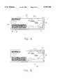
- a back side 103 of panoramic print 95includes sides 105, 107, 109 and 111. Sides 105, 107, 109 and 111 are shown in FIG. 4 also, and are provided to facilitate understanding of the orientation of the back side of print 95.
- printer 46(FIG. 2) includes a backprinter, such as an inkjet printer, for backprinting information on the back side of print 95.
- Computer 42analyzes a variable visible characteristic (e.g. color, density) of the image data to be transmitted to printer 46, and then changes a feature of the information to be backprinted on print 95 in order to substantially minimize any visibility of the information through the print.
- printer 46includes a black and white backprinter which prints black alphanumerics on the back of print 95
- computer 46will locate that portion of the image data having the highest image density (i.e. the darkest location) and then will cause the backprinter to print the black alphanumerics on the back side of print 95 opposite the high image density portion.
- computer 42analyzes the image data and determines that the image within dotted line portion 99 is dark green in color and density (a mountain). Computer 42 also determines that the image within dotted line portion 101 is light blue in color and density (sky). Computer 42 would thus instruct the backprinter to print a black date that the image was recorded within dotted line portion 99 on the back of print 95 rather than within dotted line portion 101. This is because a black date is less likely to show through a dark green portion of print 95 than a light blue portion of the print.
- An electronic camera 170includes a camera body 172 and an objective lens 174.
- An electronic image capture element 176such as a two-dimensional array of charge-coupled-devices, electronically records an image of a scene passing through objective lens 174.
- a microprocessor 178controls operation of electronic image capture element 176 and includes a memory section for storing images captured by the element 176.
- a manually operable switch 180enables a camera operator to select a designated aspect ratio for printing images captured by camera 170.
- an information exchange port 182allows images captured by the camera and information related to these images, such as designated printing aspect ratio, date of image recording and frame number, to be downloaded to computer 42 and index print generator 44 (FIG. 2).
- scanner 18(FIG. 2) is completely eliminated, because the image data is already in electronic form when recorded by the camera.
- the camera operatordownloads the image data and information related to the images via port 182 into computer 42 and index print generator 44 (the image data and related information has been digitized in the camera).
- the remainder of the process, as described in all of the embodiments described above,remains the same.
- the main difference in this embodimentis that the image data and related information is provided to computer 42 and index printer 44 directly from camera 170 rather than scanner 18, magnetic head 41 and processor 40.
- the variable visible characteristice.g. color, image density
- filmstrip 90to determine the visible composition of the variable characteristic.
Landscapes
- Physics & Mathematics (AREA)
- General Physics & Mathematics (AREA)
- Editing Of Facsimile Originals (AREA)
- Control Or Security For Electrophotography (AREA)
Abstract
Description
Claims (21)
Priority Applications (2)
| Application Number | Priority Date | Filing Date | Title |
|---|---|---|---|
| US08/608,427US5767945A (en) | 1996-02-28 | 1996-02-28 | Methods of changing the visibility of some characteristic or information to be included in a hard copy of a recorded image |
| JP9070347AJPH1023244A (en) | 1996-02-28 | 1997-02-17 | Method for changing visibility of characteristic and information added to hard copy of recorded image |
Applications Claiming Priority (1)
| Application Number | Priority Date | Filing Date | Title |
|---|---|---|---|
| US08/608,427US5767945A (en) | 1996-02-28 | 1996-02-28 | Methods of changing the visibility of some characteristic or information to be included in a hard copy of a recorded image |
Publications (1)
| Publication Number | Publication Date |
|---|---|
| US5767945Atrue US5767945A (en) | 1998-06-16 |
Family
ID=24436465
Family Applications (1)
| Application Number | Title | Priority Date | Filing Date |
|---|---|---|---|
| US08/608,427Expired - LifetimeUS5767945A (en) | 1996-02-28 | 1996-02-28 | Methods of changing the visibility of some characteristic or information to be included in a hard copy of a recorded image |
Country Status (2)
| Country | Link |
|---|---|
| US (1) | US5767945A (en) |
| JP (1) | JPH1023244A (en) |
Cited By (29)
| Publication number | Priority date | Publication date | Assignee | Title |
|---|---|---|---|---|
| US6169596B1 (en)* | 1996-11-27 | 2001-01-02 | Fuji Photo Film Co., Ltd. | Photo finishing system |
| US6181409B1 (en)* | 1998-02-13 | 2001-01-30 | Eastman Kodak Company | System for backprinting photographic media |
| US6229592B1 (en)* | 1997-07-11 | 2001-05-08 | Noritsu Koki Co., Ltd | Negative film with identification number, and photographic printing apparatus |
| US6285470B1 (en)* | 1997-07-22 | 2001-09-04 | Minolta Co., Ltd. | Image reading apparatus |
| US6311018B1 (en) | 2000-08-23 | 2001-10-30 | Eastman Kodak Company | Method of making respective prints of recorded images within successive film frames or alternatively of selected portions of the images |
| US20020071131A1 (en)* | 1999-12-14 | 2002-06-13 | Ricoh Company, Limited | Method and apparatus for color image processing, and a computer product |
| US6563542B1 (en)* | 1997-09-09 | 2003-05-13 | Olympus Optical Co., Ltd. | Electronic camera |
| US20030117502A1 (en)* | 2001-12-20 | 2003-06-26 | Heiles Lainye E. | Contact sheet file-generating digital camera |
| US6603506B2 (en)* | 1996-02-02 | 2003-08-05 | Canon Kabushiki Kaisha | Digital image-sensing apparatus and control method therefor |
| US20050157354A1 (en)* | 2004-01-21 | 2005-07-21 | Canon Kabushiki Kaisha | Image reading apparatus and image printing apparatus using the same |
| US20050157353A1 (en)* | 2004-01-16 | 2005-07-21 | Canon Kabushiki Kaisha | Image reading apparatus and image forming apparatus using the same |
| US20050179960A1 (en)* | 2004-01-16 | 2005-08-18 | Canon Kabushiki Kaisha | Image reading apparatus |
| US20050190412A1 (en)* | 2004-02-27 | 2005-09-01 | Canon Kabushiki Kaisha | Image reading apparatus and method of controlling same |
| US6950120B1 (en)* | 1997-12-03 | 2005-09-27 | Canon Kabushiki Kaisha | Camera layout for acquiring images used in panoramic synthesis |
| US20060104630A1 (en)* | 2004-11-15 | 2006-05-18 | Cornell David J | Photographic film notching scanner correction |
| US20070171460A1 (en)* | 2006-01-24 | 2007-07-26 | Lexmark International, Inc. | Photo duplexing method |
| US20090293990A1 (en)* | 2005-09-09 | 2009-12-03 | Control And Metering Limited | Modular Bag Filling Apparatus |
| US8096642B2 (en) | 1997-08-11 | 2012-01-17 | Silverbrook Research Pty Ltd | Inkjet nozzle with paddle layer arranged between first and second wafers |
| US8102568B2 (en) | 1997-07-15 | 2012-01-24 | Silverbrook Research Pty Ltd | System for creating garments using camera and encoded card |
| US8274665B2 (en) | 1997-07-15 | 2012-09-25 | Silverbrook Research Pty Ltd | Image sensing and printing device |
| US8285137B2 (en) | 1997-07-15 | 2012-10-09 | Silverbrook Research Pty Ltd | Digital camera system for simultaneous printing and magnetic recording |
| US8421869B2 (en) | 1997-07-15 | 2013-04-16 | Google Inc. | Camera system for with velocity sensor and de-blurring processor |
| US8789939B2 (en) | 1998-11-09 | 2014-07-29 | Google Inc. | Print media cartridge with ink supply manifold |
| US8823823B2 (en) | 1997-07-15 | 2014-09-02 | Google Inc. | Portable imaging device with multi-core processor and orientation sensor |
| US8866923B2 (en) | 1999-05-25 | 2014-10-21 | Google Inc. | Modular camera and printer |
| US8896724B2 (en) | 1997-07-15 | 2014-11-25 | Google Inc. | Camera system to facilitate a cascade of imaging effects |
| US8902333B2 (en) | 1997-07-15 | 2014-12-02 | Google Inc. | Image processing method using sensed eye position |
| US8908075B2 (en) | 1997-07-15 | 2014-12-09 | Google Inc. | Image capture and processing integrated circuit for a camera |
| US8936196B2 (en) | 1997-07-15 | 2015-01-20 | Google Inc. | Camera unit incorporating program script scanner |
Citations (6)
| Publication number | Priority date | Publication date | Assignee | Title |
|---|---|---|---|---|
| US4823163A (en)* | 1987-03-19 | 1989-04-18 | Societe Inter-Color | Apparatus for marking the backs of photographic proofs |
| US4903068A (en)* | 1987-07-03 | 1990-02-20 | Fuji Photo Film Co., Ltd. | Photographic printer |
| US4933773A (en)* | 1987-09-24 | 1990-06-12 | Fuji Photo Film Co., Ltd. | Photographic printing method and apparatus therefor |
| US5153715A (en)* | 1990-11-26 | 1992-10-06 | Eastman Kodak Company | Exposure determining color film scanning apparatus for a photofinishing system |
| JPH0527406A (en)* | 1991-07-18 | 1993-02-05 | Fuji Photo Film Co Ltd | Index print |
| US5319402A (en)* | 1985-10-24 | 1994-06-07 | Canon Kabushiki Kaisha | Data imprinting device for camera |
- 1996
- 1996-02-28USUS08/608,427patent/US5767945A/ennot_activeExpired - Lifetime
- 1997
- 1997-02-17JPJP9070347Apatent/JPH1023244A/enactivePending
Patent Citations (6)
| Publication number | Priority date | Publication date | Assignee | Title |
|---|---|---|---|---|
| US5319402A (en)* | 1985-10-24 | 1994-06-07 | Canon Kabushiki Kaisha | Data imprinting device for camera |
| US4823163A (en)* | 1987-03-19 | 1989-04-18 | Societe Inter-Color | Apparatus for marking the backs of photographic proofs |
| US4903068A (en)* | 1987-07-03 | 1990-02-20 | Fuji Photo Film Co., Ltd. | Photographic printer |
| US4933773A (en)* | 1987-09-24 | 1990-06-12 | Fuji Photo Film Co., Ltd. | Photographic printing method and apparatus therefor |
| US5153715A (en)* | 1990-11-26 | 1992-10-06 | Eastman Kodak Company | Exposure determining color film scanning apparatus for a photofinishing system |
| JPH0527406A (en)* | 1991-07-18 | 1993-02-05 | Fuji Photo Film Co Ltd | Index print |
Cited By (84)
| Publication number | Priority date | Publication date | Assignee | Title |
|---|---|---|---|---|
| US6603506B2 (en)* | 1996-02-02 | 2003-08-05 | Canon Kabushiki Kaisha | Digital image-sensing apparatus and control method therefor |
| US20030193569A1 (en)* | 1996-02-02 | 2003-10-16 | Yasuyuki Ogawa | Digital image-sensing apparatus and control method therefor |
| US6169596B1 (en)* | 1996-11-27 | 2001-01-02 | Fuji Photo Film Co., Ltd. | Photo finishing system |
| US6229592B1 (en)* | 1997-07-11 | 2001-05-08 | Noritsu Koki Co., Ltd | Negative film with identification number, and photographic printing apparatus |
| US9544451B2 (en) | 1997-07-12 | 2017-01-10 | Google Inc. | Multi-core image processor for portable device |
| US9338312B2 (en) | 1997-07-12 | 2016-05-10 | Google Inc. | Portable handheld device with multi-core image processor |
| US8947592B2 (en) | 1997-07-12 | 2015-02-03 | Google Inc. | Handheld imaging device with image processor provided with multiple parallel processing units |
| US8902340B2 (en) | 1997-07-12 | 2014-12-02 | Google Inc. | Multi-core image processor for portable device |
| US9124736B2 (en) | 1997-07-15 | 2015-09-01 | Google Inc. | Portable hand-held device for displaying oriented images |
| US9055221B2 (en) | 1997-07-15 | 2015-06-09 | Google Inc. | Portable hand-held device for deblurring sensed images |
| US9584681B2 (en) | 1997-07-15 | 2017-02-28 | Google Inc. | Handheld imaging device incorporating multi-core image processor |
| US9560221B2 (en) | 1997-07-15 | 2017-01-31 | Google Inc. | Handheld imaging device with VLIW image processor |
| US9432529B2 (en) | 1997-07-15 | 2016-08-30 | Google Inc. | Portable handheld device with multi-core microcoded image processor |
| US9237244B2 (en) | 1997-07-15 | 2016-01-12 | Google Inc. | Handheld digital camera device with orientation sensing and decoding capabilities |
| US9219832B2 (en) | 1997-07-15 | 2015-12-22 | Google Inc. | Portable handheld device with multi-core image processor |
| US9197767B2 (en) | 1997-07-15 | 2015-11-24 | Google Inc. | Digital camera having image processor and printer |
| US9191529B2 (en) | 1997-07-15 | 2015-11-17 | Google Inc | Quad-core camera processor |
| US9191530B2 (en) | 1997-07-15 | 2015-11-17 | Google Inc. | Portable hand-held device having quad core image processor |
| US9185247B2 (en) | 1997-07-15 | 2015-11-10 | Google Inc. | Central processor with multiple programmable processor units |
| US9185246B2 (en) | 1997-07-15 | 2015-11-10 | Google Inc. | Camera system comprising color display and processor for decoding data blocks in printed coding pattern |
| US8908051B2 (en) | 1997-07-15 | 2014-12-09 | Google Inc. | Handheld imaging device with system-on-chip microcontroller incorporating on shared wafer image processor and image sensor |
| US9179020B2 (en) | 1997-07-15 | 2015-11-03 | Google Inc. | Handheld imaging device with integrated chip incorporating on shared wafer image processor and central processor |
| US9168761B2 (en) | 1997-07-15 | 2015-10-27 | Google Inc. | Disposable digital camera with printing assembly |
| US9148530B2 (en) | 1997-07-15 | 2015-09-29 | Google Inc. | Handheld imaging device with multi-core image processor integrating common bus interface and dedicated image sensor interface |
| US9143635B2 (en) | 1997-07-15 | 2015-09-22 | Google Inc. | Camera with linked parallel processor cores |
| US9143636B2 (en) | 1997-07-15 | 2015-09-22 | Google Inc. | Portable device with dual image sensors and quad-core processor |
| US9137397B2 (en) | 1997-07-15 | 2015-09-15 | Google Inc. | Image sensing and printing device |
| US8102568B2 (en) | 1997-07-15 | 2012-01-24 | Silverbrook Research Pty Ltd | System for creating garments using camera and encoded card |
| US8274665B2 (en) | 1997-07-15 | 2012-09-25 | Silverbrook Research Pty Ltd | Image sensing and printing device |
| US8285137B2 (en) | 1997-07-15 | 2012-10-09 | Silverbrook Research Pty Ltd | Digital camera system for simultaneous printing and magnetic recording |
| US8421869B2 (en) | 1997-07-15 | 2013-04-16 | Google Inc. | Camera system for with velocity sensor and de-blurring processor |
| US9137398B2 (en) | 1997-07-15 | 2015-09-15 | Google Inc. | Multi-core processor for portable device with dual image sensors |
| US8823823B2 (en) | 1997-07-15 | 2014-09-02 | Google Inc. | Portable imaging device with multi-core processor and orientation sensor |
| US8836809B2 (en) | 1997-07-15 | 2014-09-16 | Google Inc. | Quad-core image processor for facial detection |
| US9131083B2 (en) | 1997-07-15 | 2015-09-08 | Google Inc. | Portable imaging device with multi-core processor |
| US8866926B2 (en) | 1997-07-15 | 2014-10-21 | Google Inc. | Multi-core processor for hand-held, image capture device |
| US8896720B2 (en) | 1997-07-15 | 2014-11-25 | Google Inc. | Hand held image capture device with multi-core processor for facial detection |
| US8896724B2 (en) | 1997-07-15 | 2014-11-25 | Google Inc. | Camera system to facilitate a cascade of imaging effects |
| US9124737B2 (en) | 1997-07-15 | 2015-09-01 | Google Inc. | Portable device with image sensor and quad-core processor for multi-point focus image capture |
| US8902324B2 (en) | 1997-07-15 | 2014-12-02 | Google Inc. | Quad-core image processor for device with image display |
| US8902333B2 (en) | 1997-07-15 | 2014-12-02 | Google Inc. | Image processing method using sensed eye position |
| US8902357B2 (en) | 1997-07-15 | 2014-12-02 | Google Inc. | Quad-core image processor |
| US8908069B2 (en) | 1997-07-15 | 2014-12-09 | Google Inc. | Handheld imaging device with quad-core image processor integrating image sensor interface |
| US8908075B2 (en) | 1997-07-15 | 2014-12-09 | Google Inc. | Image capture and processing integrated circuit for a camera |
| US9060128B2 (en) | 1997-07-15 | 2015-06-16 | Google Inc. | Portable hand-held device for manipulating images |
| US8947679B2 (en) | 1997-07-15 | 2015-02-03 | Google Inc. | Portable handheld device with multi-core microcoded image processor |
| US8913182B2 (en) | 1997-07-15 | 2014-12-16 | Google Inc. | Portable hand-held device having networked quad core processor |
| US8913137B2 (en) | 1997-07-15 | 2014-12-16 | Google Inc. | Handheld imaging device with multi-core image processor integrating image sensor interface |
| US8922791B2 (en) | 1997-07-15 | 2014-12-30 | Google Inc. | Camera system with color display and processor for Reed-Solomon decoding |
| US8922670B2 (en) | 1997-07-15 | 2014-12-30 | Google Inc. | Portable hand-held device having stereoscopic image camera |
| US8928897B2 (en) | 1997-07-15 | 2015-01-06 | Google Inc. | Portable handheld device with multi-core image processor |
| US8934027B2 (en) | 1997-07-15 | 2015-01-13 | Google Inc. | Portable device with image sensors and multi-core processor |
| US8934053B2 (en) | 1997-07-15 | 2015-01-13 | Google Inc. | Hand-held quad core processing apparatus |
| US8936196B2 (en) | 1997-07-15 | 2015-01-20 | Google Inc. | Camera unit incorporating program script scanner |
| US8937727B2 (en) | 1997-07-15 | 2015-01-20 | Google Inc. | Portable handheld device with multi-core image processor |
| US8913151B2 (en) | 1997-07-15 | 2014-12-16 | Google Inc. | Digital camera with quad core processor |
| US8953061B2 (en) | 1997-07-15 | 2015-02-10 | Google Inc. | Image capture device with linked multi-core processor and orientation sensor |
| US8953178B2 (en) | 1997-07-15 | 2015-02-10 | Google Inc. | Camera system with color display and processor for reed-solomon decoding |
| US8953060B2 (en) | 1997-07-15 | 2015-02-10 | Google Inc. | Hand held image capture device with multi-core processor and wireless interface to input device |
| US6285470B1 (en)* | 1997-07-22 | 2001-09-04 | Minolta Co., Ltd. | Image reading apparatus |
| US8096642B2 (en) | 1997-08-11 | 2012-01-17 | Silverbrook Research Pty Ltd | Inkjet nozzle with paddle layer arranged between first and second wafers |
| US20030146979A1 (en)* | 1997-09-09 | 2003-08-07 | Olympus Optical Co., Ltd. | Electronic camera |
| US6563542B1 (en)* | 1997-09-09 | 2003-05-13 | Olympus Optical Co., Ltd. | Electronic camera |
| US20030151668A1 (en)* | 1997-09-09 | 2003-08-14 | Olympus Optical Co., Ltd. | Electronic camera |
| US6950120B1 (en)* | 1997-12-03 | 2005-09-27 | Canon Kabushiki Kaisha | Camera layout for acquiring images used in panoramic synthesis |
| US6181409B1 (en)* | 1998-02-13 | 2001-01-30 | Eastman Kodak Company | System for backprinting photographic media |
| US8789939B2 (en) | 1998-11-09 | 2014-07-29 | Google Inc. | Print media cartridge with ink supply manifold |
| US8866923B2 (en) | 1999-05-25 | 2014-10-21 | Google Inc. | Modular camera and printer |
| US20020071131A1 (en)* | 1999-12-14 | 2002-06-13 | Ricoh Company, Limited | Method and apparatus for color image processing, and a computer product |
| US7292375B2 (en)* | 1999-12-14 | 2007-11-06 | Ricoh Company, Ltd. | Method and apparatus for color image processing, and a computer product |
| US6311018B1 (en) | 2000-08-23 | 2001-10-30 | Eastman Kodak Company | Method of making respective prints of recorded images within successive film frames or alternatively of selected portions of the images |
| US20030117502A1 (en)* | 2001-12-20 | 2003-06-26 | Heiles Lainye E. | Contact sheet file-generating digital camera |
| US6937275B2 (en)* | 2001-12-20 | 2005-08-30 | Hewlett-Packard Development Company, L.P. | Contact sheet file-generating digital camera |
| US20050179960A1 (en)* | 2004-01-16 | 2005-08-18 | Canon Kabushiki Kaisha | Image reading apparatus |
| US20050157353A1 (en)* | 2004-01-16 | 2005-07-21 | Canon Kabushiki Kaisha | Image reading apparatus and image forming apparatus using the same |
| US7317560B2 (en) | 2004-01-16 | 2008-01-08 | Canon Kabushiki Kaisha | Image reading apparatus and image forming apparatus using the same |
| US7468817B2 (en)* | 2004-01-16 | 2008-12-23 | Canon Kabushiki Kaisha | Image reading apparatus |
| US20050157354A1 (en)* | 2004-01-21 | 2005-07-21 | Canon Kabushiki Kaisha | Image reading apparatus and image printing apparatus using the same |
| US7529000B2 (en) | 2004-01-21 | 2009-05-05 | Canon Kabushiki Kaisha | Image reading apparatus and image printing apparatus using the same |
| US20050190412A1 (en)* | 2004-02-27 | 2005-09-01 | Canon Kabushiki Kaisha | Image reading apparatus and method of controlling same |
| US7408685B2 (en) | 2004-02-27 | 2008-08-05 | Canon Kabushiki Kaisha | Image reading apparatus and method of controlling same |
| US20060104630A1 (en)* | 2004-11-15 | 2006-05-18 | Cornell David J | Photographic film notching scanner correction |
| US20090293990A1 (en)* | 2005-09-09 | 2009-12-03 | Control And Metering Limited | Modular Bag Filling Apparatus |
| US20070171460A1 (en)* | 2006-01-24 | 2007-07-26 | Lexmark International, Inc. | Photo duplexing method |
Also Published As
| Publication number | Publication date |
|---|---|
| JPH1023244A (en) | 1998-01-23 |
Similar Documents
| Publication | Publication Date | Title |
|---|---|---|
| US5767945A (en) | Methods of changing the visibility of some characteristic or information to be included in a hard copy of a recorded image | |
| US7180541B2 (en) | Photographic system linked with photographic data | |
| US4689696A (en) | Hybrid image recording and reproduction system | |
| US6304345B1 (en) | Auto resoration of a print | |
| US7675556B2 (en) | Cameras, other imaging devices, and methods having non-uniform image remapping using a small data-set of distortion vectors | |
| US7072526B2 (en) | Image processing apparatus, image processing method and recording medium | |
| US5996893A (en) | Method and apparatus for visually identifying an area on a photograph or image where digital data is stored | |
| US4712909A (en) | CRT composite image printing method and apparatus | |
| US6094279A (en) | System and process for non-perceptibly integrating sound data into a printed image | |
| US20040109614A1 (en) | Red eye compensation method, image processing apparatus and method for implementing the red eye compensation method, as well as printing method and printer | |
| EP0543233A1 (en) | Photographic printer with index print generation | |
| US20030231255A1 (en) | Imaging using silver halide films with micro-lens capture, scanning and digital reconstruction | |
| US6351321B1 (en) | Data scanning and conversion system for photographic image reproduction | |
| JP3728744B2 (en) | Printing method and apparatus | |
| US5905580A (en) | System and article of manufacture for producing an index print from photographic negative strips | |
| US6825948B1 (en) | Group print, and print system and method for making group print | |
| CN100412693C (en) | Image print having one or more positive images and method for making same | |
| US6433888B1 (en) | Auto restoration of a print | |
| US20030053099A1 (en) | Image reader for efficiently and properly operating a scanner and an image processing unit | |
| US5828442A (en) | Index print attachable to an image recording medium | |
| US5606379A (en) | Method for recording and storing color images | |
| US20030161608A1 (en) | Image reproducing apparatus and image reproducing method | |
| JP2002010066A (en) | Image reproducer | |
| JP3530640B2 (en) | Digital image recording method and apparatus, and digital image processing apparatus | |
| JP2001197343A (en) | Image processing method, image outputting device, image information inputting device, hard copy producing method and image forming and recording element |
Legal Events
| Date | Code | Title | Description |
|---|---|---|---|
| AS | Assignment | Owner name:EASTMAN KODAK COMPANY, NEW YORK Free format text:ASSIGNMENT OF ASSIGNORS INTEREST;ASSIGNORS:FIELDS,ROGER A.;ATKINSON, WILLIAM C.;REEL/FRAME:007932/0168 Effective date:19960228 | |
| STCF | Information on status: patent grant | Free format text:PATENTED CASE | |
| FPAY | Fee payment | Year of fee payment:4 | |
| FEPP | Fee payment procedure | Free format text:PAYOR NUMBER ASSIGNED (ORIGINAL EVENT CODE: ASPN); ENTITY STATUS OF PATENT OWNER: LARGE ENTITY | |
| FPAY | Fee payment | Year of fee payment:8 | |
| FPAY | Fee payment | Year of fee payment:12 | |
| AS | Assignment | Owner name:CITICORP NORTH AMERICA, INC., AS AGENT, NEW YORK Free format text:SECURITY INTEREST;ASSIGNORS:EASTMAN KODAK COMPANY;PAKON, INC.;REEL/FRAME:028201/0420 Effective date:20120215 | |
| AS | Assignment | Owner name:WILMINGTON TRUST, NATIONAL ASSOCIATION, AS AGENT, Free format text:PATENT SECURITY AGREEMENT;ASSIGNORS:EASTMAN KODAK COMPANY;PAKON, INC.;REEL/FRAME:030122/0235 Effective date:20130322 Owner name:WILMINGTON TRUST, NATIONAL ASSOCIATION, AS AGENT, MINNESOTA Free format text:PATENT SECURITY AGREEMENT;ASSIGNORS:EASTMAN KODAK COMPANY;PAKON, INC.;REEL/FRAME:030122/0235 Effective date:20130322 | |
| AS | Assignment | Owner name:BARCLAYS BANK PLC, AS ADMINISTRATIVE AGENT, NEW YORK Free format text:INTELLECTUAL PROPERTY SECURITY AGREEMENT (SECOND LIEN);ASSIGNORS:EASTMAN KODAK COMPANY;FAR EAST DEVELOPMENT LTD.;FPC INC.;AND OTHERS;REEL/FRAME:031159/0001 Effective date:20130903 Owner name:JPMORGAN CHASE BANK, N.A., AS ADMINISTRATIVE, DELAWARE Free format text:INTELLECTUAL PROPERTY SECURITY AGREEMENT (FIRST LIEN);ASSIGNORS:EASTMAN KODAK COMPANY;FAR EAST DEVELOPMENT LTD.;FPC INC.;AND OTHERS;REEL/FRAME:031158/0001 Effective date:20130903 Owner name:JPMORGAN CHASE BANK, N.A., AS ADMINISTRATIVE, DELA Free format text:INTELLECTUAL PROPERTY SECURITY AGREEMENT (FIRST LIEN);ASSIGNORS:EASTMAN KODAK COMPANY;FAR EAST DEVELOPMENT LTD.;FPC INC.;AND OTHERS;REEL/FRAME:031158/0001 Effective date:20130903 Owner name:BARCLAYS BANK PLC, AS ADMINISTRATIVE AGENT, NEW YO Free format text:INTELLECTUAL PROPERTY SECURITY AGREEMENT (SECOND LIEN);ASSIGNORS:EASTMAN KODAK COMPANY;FAR EAST DEVELOPMENT LTD.;FPC INC.;AND OTHERS;REEL/FRAME:031159/0001 Effective date:20130903 Owner name:EASTMAN KODAK COMPANY, NEW YORK Free format text:RELEASE OF SECURITY INTEREST IN PATENTS;ASSIGNORS:CITICORP NORTH AMERICA, INC., AS SENIOR DIP AGENT;WILMINGTON TRUST, NATIONAL ASSOCIATION, AS JUNIOR DIP AGENT;REEL/FRAME:031157/0451 Effective date:20130903 Owner name:PAKON, INC., NEW YORK Free format text:RELEASE OF SECURITY INTEREST IN PATENTS;ASSIGNORS:CITICORP NORTH AMERICA, INC., AS SENIOR DIP AGENT;WILMINGTON TRUST, NATIONAL ASSOCIATION, AS JUNIOR DIP AGENT;REEL/FRAME:031157/0451 Effective date:20130903 Owner name:BANK OF AMERICA N.A., AS AGENT, MASSACHUSETTS Free format text:INTELLECTUAL PROPERTY SECURITY AGREEMENT (ABL);ASSIGNORS:EASTMAN KODAK COMPANY;FAR EAST DEVELOPMENT LTD.;FPC INC.;AND OTHERS;REEL/FRAME:031162/0117 Effective date:20130903 | |
| AS | Assignment | Owner name:EASTMAN KODAK COMPANY, NEW YORK Free format text:RELEASE BY SECURED PARTY;ASSIGNOR:BARCLAYS BANK PLC;REEL/FRAME:041656/0531 Effective date:20170202 | |
| AS | Assignment | Owner name:EASTMAN KODAK COMPANY, NEW YORK Free format text:RELEASE BY SECURED PARTY;ASSIGNOR:JP MORGAN CHASE BANK, N.A., AS ADMINISTRATIVE AGENT;REEL/FRAME:049814/0001 Effective date:20190617 Owner name:KODAK (NEAR EAST), INC., NEW YORK Free format text:RELEASE BY SECURED PARTY;ASSIGNOR:JP MORGAN CHASE BANK, N.A., AS ADMINISTRATIVE AGENT;REEL/FRAME:049814/0001 Effective date:20190617 Owner name:LASER PACIFIC MEDIA CORPORATION, NEW YORK Free format text:RELEASE BY SECURED PARTY;ASSIGNOR:JP MORGAN CHASE BANK, N.A., AS ADMINISTRATIVE AGENT;REEL/FRAME:049814/0001 Effective date:20190617 Owner name:QUALEX, INC., NEW YORK Free format text:RELEASE BY SECURED PARTY;ASSIGNOR:JP MORGAN CHASE BANK, N.A., AS ADMINISTRATIVE AGENT;REEL/FRAME:049814/0001 Effective date:20190617 Owner name:FPC, INC., NEW YORK Free format text:RELEASE BY SECURED PARTY;ASSIGNOR:JP MORGAN CHASE BANK, N.A., AS ADMINISTRATIVE AGENT;REEL/FRAME:049814/0001 Effective date:20190617 Owner name:NPEC, INC., NEW YORK Free format text:RELEASE BY SECURED PARTY;ASSIGNOR:JP MORGAN CHASE BANK, N.A., AS ADMINISTRATIVE AGENT;REEL/FRAME:049814/0001 Effective date:20190617 Owner name:KODAK AVIATION LEASING LLC, NEW YORK Free format text:RELEASE BY SECURED PARTY;ASSIGNOR:JP MORGAN CHASE BANK, N.A., AS ADMINISTRATIVE AGENT;REEL/FRAME:049814/0001 Effective date:20190617 Owner name:PAKON, INC., NEW YORK Free format text:RELEASE BY SECURED PARTY;ASSIGNOR:JP MORGAN CHASE BANK, N.A., AS ADMINISTRATIVE AGENT;REEL/FRAME:049814/0001 Effective date:20190617 Owner name:KODAK PORTUGUESA LIMITED, NEW YORK Free format text:RELEASE BY SECURED PARTY;ASSIGNOR:JP MORGAN CHASE BANK, N.A., AS ADMINISTRATIVE AGENT;REEL/FRAME:049814/0001 Effective date:20190617 Owner name:KODAK PHILIPPINES, LTD., NEW YORK Free format text:RELEASE BY SECURED PARTY;ASSIGNOR:JP MORGAN CHASE BANK, N.A., AS ADMINISTRATIVE AGENT;REEL/FRAME:049814/0001 Effective date:20190617 Owner name:KODAK AMERICAS, LTD., NEW YORK Free format text:RELEASE BY SECURED PARTY;ASSIGNOR:JP MORGAN CHASE BANK, N.A., AS ADMINISTRATIVE AGENT;REEL/FRAME:049814/0001 Effective date:20190617 Owner name:CREO MANUFACTURING AMERICA LLC, NEW YORK Free format text:RELEASE BY SECURED PARTY;ASSIGNOR:JP MORGAN CHASE BANK, N.A., AS ADMINISTRATIVE AGENT;REEL/FRAME:049814/0001 Effective date:20190617 Owner name:KODAK REALTY, INC., NEW YORK Free format text:RELEASE BY SECURED PARTY;ASSIGNOR:JP MORGAN CHASE BANK, N.A., AS ADMINISTRATIVE AGENT;REEL/FRAME:049814/0001 Effective date:20190617 Owner name:FAR EAST DEVELOPMENT LTD., NEW YORK Free format text:RELEASE BY SECURED PARTY;ASSIGNOR:JP MORGAN CHASE BANK, N.A., AS ADMINISTRATIVE AGENT;REEL/FRAME:049814/0001 Effective date:20190617 Owner name:KODAK IMAGING NETWORK, INC., NEW YORK Free format text:RELEASE BY SECURED PARTY;ASSIGNOR:JP MORGAN CHASE BANK, N.A., AS ADMINISTRATIVE AGENT;REEL/FRAME:049814/0001 Effective date:20190617 | |
| AS | Assignment | Owner name:FAR EAST DEVELOPMENT LTD., NEW YORK Free format text:RELEASE BY SECURED PARTY;ASSIGNOR:BARCLAYS BANK PLC;REEL/FRAME:052773/0001 Effective date:20170202 Owner name:FPC INC., NEW YORK Free format text:RELEASE BY SECURED PARTY;ASSIGNOR:BARCLAYS BANK PLC;REEL/FRAME:052773/0001 Effective date:20170202 Owner name:KODAK PHILIPPINES LTD., NEW YORK Free format text:RELEASE BY SECURED PARTY;ASSIGNOR:BARCLAYS BANK PLC;REEL/FRAME:052773/0001 Effective date:20170202 Owner name:KODAK (NEAR EAST) INC., NEW YORK Free format text:RELEASE BY SECURED PARTY;ASSIGNOR:BARCLAYS BANK PLC;REEL/FRAME:052773/0001 Effective date:20170202 Owner name:QUALEX INC., NEW YORK Free format text:RELEASE BY SECURED PARTY;ASSIGNOR:BARCLAYS BANK PLC;REEL/FRAME:052773/0001 Effective date:20170202 Owner name:NPEC INC., NEW YORK Free format text:RELEASE BY SECURED PARTY;ASSIGNOR:BARCLAYS BANK PLC;REEL/FRAME:052773/0001 Effective date:20170202 Owner name:LASER PACIFIC MEDIA CORPORATION, NEW YORK Free format text:RELEASE BY SECURED PARTY;ASSIGNOR:BARCLAYS BANK PLC;REEL/FRAME:052773/0001 Effective date:20170202 Owner name:KODAK AMERICAS LTD., NEW YORK Free format text:RELEASE BY SECURED PARTY;ASSIGNOR:BARCLAYS BANK PLC;REEL/FRAME:052773/0001 Effective date:20170202 Owner name:EASTMAN KODAK COMPANY, NEW YORK Free format text:RELEASE BY SECURED PARTY;ASSIGNOR:BARCLAYS BANK PLC;REEL/FRAME:052773/0001 Effective date:20170202 Owner name:KODAK REALTY INC., NEW YORK Free format text:RELEASE BY SECURED PARTY;ASSIGNOR:BARCLAYS BANK PLC;REEL/FRAME:052773/0001 Effective date:20170202 |