US5767591A - Method and apparatus for providing startup power to a genset-backed uninterruptible power supply - Google Patents
Method and apparatus for providing startup power to a genset-backed uninterruptible power supplyDownload PDFInfo
- Publication number
- US5767591A US5767591AUS08/709,578US70957896AUS5767591AUS 5767591 AUS5767591 AUS 5767591AUS 70957896 AUS70957896 AUS 70957896AUS 5767591 AUS5767591 AUS 5767591A
- Authority
- US
- United States
- Prior art keywords
- power
- energy storage
- power supply
- level
- circuit
- Prior art date
- Legal status (The legal status is an assumption and is not a legal conclusion. Google has not performed a legal analysis and makes no representation as to the accuracy of the status listed.)
- Expired - Lifetime
Links
- 238000000034methodMethods0.000titleclaimsdescription7
- 238000004146energy storageMethods0.000claimsabstractdescription34
- 238000012544monitoring processMethods0.000claimsdescription21
- 238000012546transferMethods0.000claimsdescription11
- 239000007858starting materialSubstances0.000claimsdescription5
- 238000006243chemical reactionMethods0.000claims1
- 239000002253acidSubstances0.000description4
- 239000003990capacitorSubstances0.000description3
- 238000010586diagramMethods0.000description3
- 230000007812deficiencyEffects0.000description2
- 239000000446fuelSubstances0.000description2
- 238000012423maintenanceMethods0.000description2
- 238000012986modificationMethods0.000description2
- 230000004048modificationEffects0.000description2
- 230000007797corrosionEffects0.000description1
- 238000005260corrosionMethods0.000description1
- 230000002950deficientEffects0.000description1
- 239000002283diesel fuelSubstances0.000description1
- 230000007613environmental effectEffects0.000description1
- 238000012545processingMethods0.000description1
- 239000000126substanceSubstances0.000description1
- 238000001356surgical procedureMethods0.000description1
Images


Classifications
- H—ELECTRICITY
- H02—GENERATION; CONVERSION OR DISTRIBUTION OF ELECTRIC POWER
- H02J—CIRCUIT ARRANGEMENTS OR SYSTEMS FOR SUPPLYING OR DISTRIBUTING ELECTRIC POWER; SYSTEMS FOR STORING ELECTRIC ENERGY
- H02J9/00—Circuit arrangements for emergency or stand-by power supply, e.g. for emergency lighting
- H02J9/04—Circuit arrangements for emergency or stand-by power supply, e.g. for emergency lighting in which the distribution system is disconnected from the normal source and connected to a standby source
- H02J9/06—Circuit arrangements for emergency or stand-by power supply, e.g. for emergency lighting in which the distribution system is disconnected from the normal source and connected to a standby source with automatic change-over, e.g. UPS systems
- H02J9/062—Circuit arrangements for emergency or stand-by power supply, e.g. for emergency lighting in which the distribution system is disconnected from the normal source and connected to a standby source with automatic change-over, e.g. UPS systems for AC powered loads
- H—ELECTRICITY
- H02—GENERATION; CONVERSION OR DISTRIBUTION OF ELECTRIC POWER
- H02J—CIRCUIT ARRANGEMENTS OR SYSTEMS FOR SUPPLYING OR DISTRIBUTING ELECTRIC POWER; SYSTEMS FOR STORING ELECTRIC ENERGY
- H02J7/00—Circuit arrangements for charging or depolarising batteries or for supplying loads from batteries
- H02J7/02—Circuit arrangements for charging or depolarising batteries or for supplying loads from batteries for charging batteries from AC mains by converters
- H02J7/04—Regulation of charging current or voltage
- H02J7/06—Regulation of charging current or voltage using discharge tubes or semiconductor devices
- H02J7/08—Regulation of charging current or voltage using discharge tubes or semiconductor devices using discharge tubes only
- Y—GENERAL TAGGING OF NEW TECHNOLOGICAL DEVELOPMENTS; GENERAL TAGGING OF CROSS-SECTIONAL TECHNOLOGIES SPANNING OVER SEVERAL SECTIONS OF THE IPC; TECHNICAL SUBJECTS COVERED BY FORMER USPC CROSS-REFERENCE ART COLLECTIONS [XRACs] AND DIGESTS
- Y02—TECHNOLOGIES OR APPLICATIONS FOR MITIGATION OR ADAPTATION AGAINST CLIMATE CHANGE
- Y02B—CLIMATE CHANGE MITIGATION TECHNOLOGIES RELATED TO BUILDINGS, e.g. HOUSING, HOUSE APPLIANCES OR RELATED END-USER APPLICATIONS
- Y02B70/00—Technologies for an efficient end-user side electric power management and consumption
- Y02B70/30—Systems integrating technologies related to power network operation and communication or information technologies for improving the carbon footprint of the management of residential or tertiary loads, i.e. smart grids as climate change mitigation technology in the buildings sector, including also the last stages of power distribution and the control, monitoring or operating management systems at local level
- Y—GENERAL TAGGING OF NEW TECHNOLOGICAL DEVELOPMENTS; GENERAL TAGGING OF CROSS-SECTIONAL TECHNOLOGIES SPANNING OVER SEVERAL SECTIONS OF THE IPC; TECHNICAL SUBJECTS COVERED BY FORMER USPC CROSS-REFERENCE ART COLLECTIONS [XRACs] AND DIGESTS
- Y04—INFORMATION OR COMMUNICATION TECHNOLOGIES HAVING AN IMPACT ON OTHER TECHNOLOGY AREAS
- Y04S—SYSTEMS INTEGRATING TECHNOLOGIES RELATED TO POWER NETWORK OPERATION, COMMUNICATION OR INFORMATION TECHNOLOGIES FOR IMPROVING THE ELECTRICAL POWER GENERATION, TRANSMISSION, DISTRIBUTION, MANAGEMENT OR USAGE, i.e. SMART GRIDS
- Y04S20/00—Management or operation of end-user stationary applications or the last stages of power distribution; Controlling, monitoring or operating thereof
- Y04S20/20—End-user application control systems
Definitions
- UPSuninterruptible power supply
- GENSETstandby diesel generator set
- UPS systemsare often installed in environments in which continuous operation is critical, even in the event of a loss of main power.
- such systemsmay be installed in airports, hospitals, processing plants and computer centers.
- a total loss of powermay lead to catastrophic results (e.g., a loss of power in the middle of surgery may result in the death of the patient).
- circuitryIn typical UPS systems, circuitry is provided that monitors power being supplied from a main source of power, often via a connection to a DC buss.
- a bank of batteriesoften lead-acid batteries, is connected to a DC buss that feeds the critical load to provide temporary power as soon as the voltage on the buss drops below battery voltage.
- the batteriesare intended to provide temporary power only until a standby power source, such as the GENSET described above, can be brought on-line. Therefore, the batteries typically provide power for a very short time, until the standby generator is running at full speed and providing backup power.
- an uninterruptible power supplyin which the backup power source receives its initial power from an energy storage system that also provides the temporary power to the critical load.
- the preferred embodimentsinclude flywheel energy storage devices that provide both the temporary power during the time the backup power source is being accelerated to full speed, as well as the startup power to the backup power source.
- the flywheel energy storage devicewhich is activated by a monitoring circuit whenever a main power fault is detected, provides temporary power throughout the entire powerup cycle of the GENSET. While temporary power is being supplied, additional power is provided from the flywheel device to the GENSET until the GENSET is operating self-sufficiently (i.e., running on fuel such as diesel or gasoline), which is typically less than thirty seconds.
- Temporary poweris continuously supplied from the flywheel until the GENSET reaches a predetermined rotational speed (where the appropriate level of power can be supplied by the GENSET).
- FIG. 1is a block diagram of a conventional GENSET-backed battery powered uninterruptible power supply
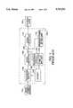
- FIG. 2is a block diagram of a GENSET-backed uninterruptible power supply constructed in accordance with the principles of the present invention.
- FIG. 3is a schematic block diagram of a sample converter circuit that may be used in the uninterruptible power supply of FIG. 2 to provide startup power to the backup source and temporary power to the critical load from a single energy storage system in accordance with the principles of the present invention.
- FIG. 1shows a conventional GENSET-backed battery powered uninterruptible power supply 100 (UPS 100).
- UPS 100is connected between main power source 102, which may simply be power supplied from a utility company, and critical load 104.
- Critical load 104represents any one of several different applications in which a continuous supply of power is critical, such as the aforementioned airport, hospital, etc.
- UPS 100provides backup power to critical load 104 in the event that main power source 102 fails.
- UPS 100includes a transfer switch 106, an AC-to-DC converter 108, a DC-to-AC converter 110, a GENSET 112, a monitoring circuit 114, a temporary power battery bank 116 and a startup battery 118.
- Transfer switch 106transfers the power supply from main power source 102 to GENSET 112 after main source 102 fails and GENSET 112 is providing power at a sufficient level.
- AC-to-DC converter 108takes the AC power provided by either main power source 102 or GENSET 112 and converts it to DC power.
- Converter 108may be a simple rectifier circuit, or it may be any other conventional circuit that is used to convert power from AC to DC as long as the proper power levels are maintained.
- Converter 110may be a simple inverter circuit, or it may be any other conventional circuit used to convert power from DC to AC.
- DC buss 120is monitored by monitoring circuit 114 (while monitoring circuit 114 is only shown to receive signals indicative of the status of DC buss 120, additional "main power failure" input signals may be received by monitoring the input to AC-to-DC converter 108 and/or the output from DC-to-AC converter 110). Once a main power failure has been detected, monitoring circuit 114 sends signals along line 124 that may cause backup power to be supplied to critical load 104 from GENSET 112. Temporary power battery bank 116 supplies DC power to DC buss 120 as soon as the voltage on DC buss 120 drops below battery voltage. Battery bank 116 will continue to supply power to buss 120 until either the batteries are drained or until adequate power is being supplied to critical load 104 from another source (i.e., either main power source 102 or GENSET 112).
- the signal on line 124triggers GENSET 112 to begin a powerup cycle.
- GENSET 112which includes a startup motor (not shown) similar to an automobile starter that is driven by startup battery 118, will powerup normally to provide backup power to critical load 104 as long as startup battery 118 is not defective (unless GENSET 112 has a major fault itself).
- Startup battery 118may be, for example, a 24 volt battery that needs somewhat constant maintenance to insure proper operation. Faults may occur, for example, due to the corrosive nature of the terminal connections between battery 118 and GENSET 112, or battery 118 may fail due to changing environmental conditions (e.g., excessive heat or cold).
- typical lead-acid batterieshave a limited lifespan (anywhere from three to eight years, on the average) that, unfortunately, may expire near the critical moment it is needed.
- FIG. 2shows a GENSET-backed uninterruptible power supply 200 (UPS 200) that, in accordance with the principles of the present invention, overcomes the deficiencies of conventional GENSET-backed UPS systems.
- UPS 200includes many of the same components as UPS 100. For example, transfer switch 106, AC-to-DC converter 108, DC-to-AC converter 110 and GENSET 112.
- the monitoring circuitis shown as monitoring circuit 214 in view of the fact that different control signals are required in UPS 200 (e.g., the signal on line 222).
- UPS 200also includes energy storage system 230, which is preferably a flywheel energy storage system, but may be a bank of batteries similar to temporary power battery bank 116.
- energy storage system 230is indeed a bank of batteries, however, additional circuit modifications (not shown) must be made to step the DC voltage down to 24 volts (the battery bank alternative is somewhat less practical because the additional circuitry may include another pair of converters to go from DC to AC and back).
- UPS system 230While the reliability of the UPS system is improved in either instance due to the use of a single source of power for DC buss 120 and for GENSET 112, the most significant increase in reliability is achieved when energy storage system 230 is a flywheel energy storage device.
- a flywheel energy storage deviceprovides a more reliable, better monitored source of power for both the GENSET and the temporary power requirement because it is a mechanical system, rather than a chemical system.
- UPS 200normally operates in a monitoring mode, whereby monitoring circuit 214 monitors DC buss 120 until the voltage on buss 120 drops below a predetermined threshold (as described above, monitoring circuit 214 may also be activated by sensor inputs at either the input to AC-to-DC converter 108, the output to DC-to-AC converter 110, or both).
- monitoring circuit 214detects a failure, a trigger signal is applied via line 222 that brings energy storage system 230 online to DC buss 120 (to provide temporary power until GENSET 112 is up and running).
- the trigger signalalso directs energy storage system 230 to provide startup power to GENSET 112, which is switched on by a trigger signal on line 224.
- Energy storage system 230provides startup power to GENSET 112 until GENSET 112 is running independently on its external fuel supply (e.g., diesel fuel or gasoline). Once GENSET 112 is producing power at the proper level, transfer switch 106 transfers the input power from main power source 102 to GENSET 112 and energy storage system 230 ceases to provide power to DC buss 120.
- GENSET 112is running independently on its external fuel supply (e.g., diesel fuel or gasoline).
- FIG. 3shows a representative example of a converter circuit 300 that may be used by energy storage system 230 of FIG. 2 to provide startup power to GENSET 112 from the same source that supplies temporary backup power to DC buss 120.
- Converter circuit 300includes flywheel energy storage device 302, transformers 304, 306 and 308, diode pairs 310, 312, 314, capacitor 316, terminal 318, diode pairs 320, 322 and 324, and terminals 326.
- Flywheel device 302produces a three-phase AC output (i.e., phases A, B and C) that is connected across the primaries of transformers 304, 306 and 308.
- the three phase output of the secondaries of transformers 304, 306 and 308are connected across diode pairs 310, 312 and 314, which rectify the AC output into a DC output.
- the DC signalmay be further refined by the addition of small filter capacitor 316 (shown in a dashed box to indicate that the use of capacitor 316 is optional).
- the 24 volt DC outputis provided at terminal 318, which may be connected directly to the starter of the engine that drives GENSET 112.
- the three-phase output of flywheel device 302is also fed to diode pairs 320, 322 and 324, which rectify the three-phase output into a high voltage DC signal that is connected to buss 120 via terminals 326.
- FIG. 3shows one specific configuration of a converter circuit to produce a 24 volt output from energy storage system 230
- other configurationsmay also be used without departing from the spirit of the present invention.
- a single three-phase transformercould be used in place of individual transformers 304, 306 and 308.
- Another configurationmay make use of only two outputs from the secondary and two diode pairs to produce the 24 volt output signal (but the use of all three phases is preferred).
Landscapes
- Engineering & Computer Science (AREA)
- Power Engineering (AREA)
- Business, Economics & Management (AREA)
- Emergency Management (AREA)
- Stand-By Power Supply Arrangements (AREA)
- Power Sources (AREA)
- Charge And Discharge Circuits For Batteries Or The Like (AREA)
Abstract
Description
This invention relates to uninterruptible power supply (UPS) systems, and more particularly toward UPS systems that include a standby power source, such as a standby diesel generator set (i.e., a GENSET).
UPS systems are often installed in environments in which continuous operation is critical, even in the event of a loss of main power. For example, such systems may be installed in airports, hospitals, processing plants and computer centers. In each case, a total loss of power may lead to catastrophic results (e.g., a loss of power in the middle of surgery may result in the death of the patient).
In typical UPS systems, circuitry is provided that monitors power being supplied from a main source of power, often via a connection to a DC buss. A bank of batteries, often lead-acid batteries, is connected to a DC buss that feeds the critical load to provide temporary power as soon as the voltage on the buss drops below battery voltage. The batteries are intended to provide temporary power only until a standby power source, such as the GENSET described above, can be brought on-line. Therefore, the batteries typically provide power for a very short time, until the standby generator is running at full speed and providing backup power.
One deficiency of traditional lead-acid battery based UPS systems is that the standby power source receives its initial startup power from a separate starter battery. These lead-acid batteries frequently fail due to improper maintenance or mis-charging due to battery terminal corrosion. Therefore, if the starter battery fails, backup power will only be supplied until the bank of batteries is drained, because the GENSET (like an automobile, for instance) needs external power to get started.
In view of the foregoing, it is an object of the present invention to provide an improved uninterruptible power supply in which startup power is more reliably provided to the backup power source.
It is also an object of the present invention to provide an improved method of supplying startup power to the backup power source of an uninterruptible power supply.
These and other objects of the invention are accomplished in accordance with the principles of the invention by providing an uninterruptible power supply in which the backup power source receives its initial power from an energy storage system that also provides the temporary power to the critical load. The preferred embodiments include flywheel energy storage devices that provide both the temporary power during the time the backup power source is being accelerated to full speed, as well as the startup power to the backup power source. The flywheel energy storage device, which is activated by a monitoring circuit whenever a main power fault is detected, provides temporary power throughout the entire powerup cycle of the GENSET. While temporary power is being supplied, additional power is provided from the flywheel device to the GENSET until the GENSET is operating self-sufficiently (i.e., running on fuel such as diesel or gasoline), which is typically less than thirty seconds. Temporary power is continuously supplied from the flywheel until the GENSET reaches a predetermined rotational speed (where the appropriate level of power can be supplied by the GENSET).
Further features of the invention, its nature and various advantages will be more apparent from the accompanying drawings and the following detailed description of the preferred embodiments.
FIG. 1 is a block diagram of a conventional GENSET-backed battery powered uninterruptible power supply;
FIG. 2 is a block diagram of a GENSET-backed uninterruptible power supply constructed in accordance with the principles of the present invention; and
FIG. 3 is a schematic block diagram of a sample converter circuit that may be used in the uninterruptible power supply of FIG. 2 to provide startup power to the backup source and temporary power to the critical load from a single energy storage system in accordance with the principles of the present invention.
FIG. 1 shows a conventional GENSET-backed battery powered uninterruptible power supply 100 (UPS 100). UPS 100 is connected betweenmain power source 102, which may simply be power supplied from a utility company, andcritical load 104.Critical load 104 represents any one of several different applications in which a continuous supply of power is critical, such as the aforementioned airport, hospital, etc. UPS 100 provides backup power tocritical load 104 in the event thatmain power source 102 fails.
UPS 100 includes atransfer switch 106, an AC-to-DC converter 108, a DC-to-AC converter 110, a GENSET 112, amonitoring circuit 114, a temporarypower battery bank 116 and astartup battery 118.Transfer switch 106 transfers the power supply frommain power source 102 to GENSET 112 aftermain source 102 fails and GENSET 112 is providing power at a sufficient level. AC-to-DC converter 108 takes the AC power provided by eithermain power source 102 or GENSET 112 and converts it to DC power.Converter 108 may be a simple rectifier circuit, or it may be any other conventional circuit that is used to convert power from AC to DC as long as the proper power levels are maintained. This is typically accomplished by providing DC toDC buss 120 at a level of approximately 480 volts. The DC power is fed acrossDC buss 120 to DC-to-AC converter 110, which converts it back to AC power.Converter 110 may be a simple inverter circuit, or it may be any other conventional circuit used to convert power from DC to AC.
The signal online 124 triggers GENSET 112 to begin a powerup cycle. GENSET 112, which includes a startup motor (not shown) similar to an automobile starter that is driven bystartup battery 118, will powerup normally to provide backup power tocritical load 104 as long asstartup battery 118 is not defective (unless GENSET 112 has a major fault itself). The potential problem occurs because GENSET 112 is relying onstartup battery 118 for startup power.Startup battery 118 may be, for example, a 24 volt battery that needs somewhat constant maintenance to insure proper operation. Faults may occur, for example, due to the corrosive nature of the terminal connections betweenbattery 118 and GENSET 112, orbattery 118 may fail due to changing environmental conditions (e.g., excessive heat or cold). Additionally, typical lead-acid batteries have a limited lifespan (anywhere from three to eight years, on the average) that, unfortunately, may expire near the critical moment it is needed.
FIG. 2 shows a GENSET-backed uninterruptible power supply 200 (UPS 200) that, in accordance with the principles of the present invention, overcomes the deficiencies of conventional GENSET-backed UPS systems. UPS 200 includes many of the same components as UPS 100. For example,transfer switch 106, AC-to-DC converter 108, DC-to-AC converter 110 and GENSET 112. The monitoring circuit is shown as monitoring circuit 214 in view of the fact that different control signals are required in UPS 200 (e.g., the signal on line 222). UPS 200 also includesenergy storage system 230, which is preferably a flywheel energy storage system, but may be a bank of batteries similar to temporarypower battery bank 116. Ifenergy storage system 230 is indeed a bank of batteries, however, additional circuit modifications (not shown) must be made to step the DC voltage down to 24 volts (the battery bank alternative is somewhat less practical because the additional circuitry may include another pair of converters to go from DC to AC and back).
While the reliability of the UPS system is improved in either instance due to the use of a single source of power forDC buss 120 and for GENSET 112, the most significant increase in reliability is achieved whenenergy storage system 230 is a flywheel energy storage device. A flywheel energy storage device provides a more reliable, better monitored source of power for both the GENSET and the temporary power requirement because it is a mechanical system, rather than a chemical system.
UPS 200 normally operates in a monitoring mode, whereby monitoring circuit 214monitors DC buss 120 until the voltage onbuss 120 drops below a predetermined threshold (as described above, monitoring circuit 214 may also be activated by sensor inputs at either the input to AC-to-DC converter 108, the output to DC-to-AC converter 110, or both). Once monitoring circuit 214 detects a failure, a trigger signal is applied vialine 222 that bringsenergy storage system 230 online to DC buss 120 (to provide temporary power until GENSET 112 is up and running). The trigger signal also directsenergy storage system 230 to provide startup power to GENSET 112, which is switched on by a trigger signal online 224.Energy storage system 230 provides startup power to GENSET 112 until GENSET 112 is running independently on its external fuel supply (e.g., diesel fuel or gasoline). Once GENSET 112 is producing power at the proper level,transfer switch 106 transfers the input power frommain power source 102 to GENSET 112 andenergy storage system 230 ceases to provide power toDC buss 120.
FIG. 3 shows a representative example of aconverter circuit 300 that may be used byenergy storage system 230 of FIG. 2 to provide startup power to GENSET 112 from the same source that supplies temporary backup power toDC buss 120.Converter circuit 300 includes flywheelenergy storage device 302,transformers diode pairs terminal 318,diode pairs terminals 326.Flywheel device 302 produces a three-phase AC output (i.e., phases A, B and C) that is connected across the primaries oftransformers
If the three phase output is at 480 volts AC, for example,transformers transformers diode pairs terminal 318, which may be connected directly to the starter of the engine that drivesGENSET 112. The three-phase output offlywheel device 302 is also fed to diode pairs 320, 322 and 324, which rectify the three-phase output into a high voltage DC signal that is connected tobuss 120 viaterminals 326.
Persons skilled in the art will appreciate that, although FIG. 3 shows one specific configuration of a converter circuit to produce a 24 volt output fromenergy storage system 230, other configurations may also be used without departing from the spirit of the present invention. For example, a single three-phase transformer could be used in place ofindividual transformers
It will be understood that the foregoing is only illustrative of the principles of the invention, and that various modifications can be made by those skilled in the art without departing from the scope and spirit of the invention.
Claims (20)
1. An uninterruptible power supply for providing continuous power to a critical load, said uninterruptible power supply comprising:
a transfer switch coupled to a main power source, said transfer switch having an output;
an AC-to-DC converter circuit having an input coupled to said output of said transfer switch, and an output;
a DC-to-AC converter circuit having an input coupled to said output of said AC-to-DC converter circuit, and an output;
a monitoring circuit that monitors for a power failure;
a backup generator electrically coupled to said transfer switch and to said monitoring circuit, said backup generator being capable of providing replacement power to said critical load in the event of a power failure, said generator having a startup circuit; and
an energy storage system electrically coupled to the input of said DC-to-AC converter, to said startup circuit of said generator and to the monitoring circuit, said power failure detected by said monitoring circuit causing said energy storage system to provide temporary power to said critical load and startup power to said generator at least until said generator is running independently from said startup power.
2. The uninterruptible power supply of claim 1, wherein said energy storage system includes at least one flywheel energy storage device.
3. The uninterruptible power supply of claim 2, wherein said monitoring circuit monitors said output of said AC-to-DC converter.
4. The uninterruptible power supply of claim 2, wherein said monitoring circuit monitors said output of said transfer switch.
5. The uninterruptible power supply of claim 2, wherein said monitoring circuit monitors said output of said DC-to-AC converter.
6. The uninterruptible power supply of claim 2, wherein said energy storage system further includes a first converter circuit coupled to said input of said DC-to-AC converter circuit that converts AC power from said at least one flywheel device to DC at a first level, and a second converter circuit coupled to said startup circuit of said generator that converts AC power from said at least one flywheel device to DC at a second level.
7. The uninterruptible power supply of claim 6, wherein said first level is about 480 volts.
8. The uninterruptible power supply of claim 6, wherein said second level is about 24 volts.
9. The uninterruptible power supply of claim 6, wherein said second converter circuit comprises:
a stepdown circuit for reducing the output voltage to approximately said second level; and
a rectification circuit for rectifying said reduced AC voltage to DC voltage.
10. The uninterruptible power supply of claim 9, wherein said stepdown circuit comprises at least one transformer to provide at least a one-phase output signal.
11. The uninterruptible power supply of claim 10, wherein said rectification circuit comprises at least two pair of diodes coupled together to rectify said at least a one-phase output signal.
12. The uninterruptible power supply of claim 9, wherein said stepdown circuit comprises three transformers coupled together to provide a three-phase output signal.
13. The uninterruptible power supply of claim 12, wherein said rectification circuit comprises three pairs of diodes coupled together to rectify said three-phase output signal.
14. The uninterruptible power supply of claim 9, wherein said stepdown circuit comprises a three-phase transformer that provides a three-phase output signal.
15. An energy storage system for use in an uninterruptible power supply that provides backup power to a critical load from a secondary power source, said energy storage system comprising:
an energy storage device that produces voltage at a first level, said first level being related to said backup power required by said critical load; and
a conversion circuit for converting said voltage from said first level to a second level that may be used to start said secondary power source at least until said secondary power source is running independently from said second level voltage.
16. The energy storage system of claim 15, wherein said energy storage device is a flywheel energy storage device.
17. A method for providing backup power to a critical load in the event of a power failure, said method comprising the steps of:
monitoring for said power failure;
producing a trigger signal to generate backup power from a backup generator when said step of monitoring detects a power failure;
providing temporary power to said critical load until said backup generator comes online; and
providing startup power to said backup generator at least until said backup generator is running independently from said startup power, said temporary power and said startup power being supplied from a single energy storage system.
18. The method of claim 17, wherein said energy storage system includes a flywheel energy storage device.
19. The method of claim 18, wherein said step of providing temporary power comprises the steps of:
producing AC power at a first level;
rectifying said AC power at said first level to DC;
inverting said rectified DC to AC; and
providing said inverted AC to said critical load.
20. The method of claim 19, wherein said step of providing startup power comprises the steps of:
stepping down said produced AC power from said first level to a second level;
rectifying said stepped down AC power to DC at said stepped down level; and
providing said stepped down DC to a starter motor of said backup generator.
Priority Applications (9)
| Application Number | Priority Date | Filing Date | Title |
|---|---|---|---|
| US08/709,578US5767591A (en) | 1996-09-09 | 1996-09-09 | Method and apparatus for providing startup power to a genset-backed uninterruptible power supply |
| EP97940968AEP0925628B1 (en) | 1996-09-09 | 1997-09-09 | Methods and apparatus for providing startup power to a genset-backed uninterruptible power supply |
| DE69714746TDE69714746T2 (en) | 1996-09-09 | 1997-09-09 | METHOD AND DEVICE FOR SUPPLYING A GENERATOR MACHINE SUPPORT UNINTERRUPTIBLE POWER SUPPLY WITH STARTING ENERGY |
| PCT/US1997/015956WO1998010503A1 (en) | 1996-09-09 | 1997-09-09 | Methods and apparatus for providing startup power to a genset-backed uninterruptible power supply |
| AU42630/97AAU731620B2 (en) | 1996-09-09 | 1997-09-09 | Methods and apparatus for providing startup power to a genset-backed uninterruptible power supply |
| AT97940968TATE222416T1 (en) | 1996-09-09 | 1997-09-09 | METHOD AND DEVICE FOR SUPPLYING A GENERATOR MACHINE SET-SUPPORTED UNINTERRUPTIBLE POWER SUPPLY WITH STARTING ENERGY |
| JP10512999AJP2001502519A (en) | 1996-09-09 | 1997-09-09 | Method and apparatus for providing startup power to a GENSET-BACKED uninterruptible power supply |
| BR9712812-0ABR9712812A (en) | 1996-09-09 | 1997-09-09 | Methods and apparatus for providing starting power for a spare generator set for an uninterrupted power supply |
| CA002264614ACA2264614C (en) | 1996-09-09 | 1997-09-09 | Methods and apparatus for providing startup power to a genset-backed uninterruptible power supply |
Applications Claiming Priority (1)
| Application Number | Priority Date | Filing Date | Title |
|---|---|---|---|
| US08/709,578US5767591A (en) | 1996-09-09 | 1996-09-09 | Method and apparatus for providing startup power to a genset-backed uninterruptible power supply |
Publications (1)
| Publication Number | Publication Date |
|---|---|
| US5767591Atrue US5767591A (en) | 1998-06-16 |
Family
ID=24850439
Family Applications (1)
| Application Number | Title | Priority Date | Filing Date |
|---|---|---|---|
| US08/709,578Expired - LifetimeUS5767591A (en) | 1996-09-09 | 1996-09-09 | Method and apparatus for providing startup power to a genset-backed uninterruptible power supply |
Country Status (9)
| Country | Link |
|---|---|
| US (1) | US5767591A (en) |
| EP (1) | EP0925628B1 (en) |
| JP (1) | JP2001502519A (en) |
| AT (1) | ATE222416T1 (en) |
| AU (1) | AU731620B2 (en) |
| BR (1) | BR9712812A (en) |
| CA (1) | CA2264614C (en) |
| DE (1) | DE69714746T2 (en) |
| WO (1) | WO1998010503A1 (en) |
Cited By (74)
| Publication number | Priority date | Publication date | Assignee | Title |
|---|---|---|---|---|
| US5939799A (en)* | 1997-07-16 | 1999-08-17 | Storage Technology Corporation | Uninterruptible power supply with an automatic transfer switch |
| US6108220A (en)* | 1998-02-20 | 2000-08-22 | Union Switch & Signal, Inc. | Solid state fail-safe control of an AC load utilizing synchronous switching |
| US6111764A (en)* | 1998-10-12 | 2000-08-29 | Sanyo Denki Co., Ltd. | Power failure-free power supply apparatus |
| US6134124A (en)* | 1999-05-12 | 2000-10-17 | Abb Power T&D Company Inc. | Universal distributed-resource interface |
| US6169390B1 (en) | 1999-05-12 | 2001-01-02 | Abb Power T&D Company Inc. | Flywheel-microturbine system |
| US6172432B1 (en) | 1999-06-18 | 2001-01-09 | Gen-Tran Corporation | Automatic transfer switch |
| US6175166B1 (en) | 1999-06-14 | 2001-01-16 | Abb Power T&D Company Inc. | System for mitigating voltage disturbances and interruptions for power distribution applications |
| US6181028B1 (en)* | 1999-08-19 | 2001-01-30 | Generac Power Systems, Inc. | Transfer mechanism for transferring power between a utility source and a stand-by generator |
| US6184593B1 (en) | 1999-07-29 | 2001-02-06 | Abb Power T&D Company Inc. | Uninterruptible power supply |
| WO2001037397A1 (en)* | 1999-11-03 | 2001-05-25 | Active Power, Inc. | Integrated flywheel uninterruptible power supply system |
| US6294886B1 (en)* | 1998-08-28 | 2001-09-25 | Alstom France Sa | Supply system for an electric traction vehicle |
| US6304005B1 (en)* | 1998-03-27 | 2001-10-16 | Canon Kabushiki Kaisha | Power supply apparatus and method, and fabrication apparatus |
| US6304006B1 (en) | 2000-12-28 | 2001-10-16 | Abb T&D Technology Ltd. | Energy management uninterruptible power supply system |
| WO2001093410A1 (en)* | 2000-05-31 | 2001-12-06 | Sure Power Corporation | Power system utilizing a dc bus |
| US6433444B1 (en) | 2000-02-18 | 2002-08-13 | General Electric Company | Modular fault tolerant power distribution system |
| WO2002063744A1 (en)* | 2001-02-06 | 2002-08-15 | American Power Conversion Corporation | Integrated uninterruptible power supply enclosure |
| US6486627B1 (en)* | 2000-06-23 | 2002-11-26 | Indigo Energy, Inc. | Flywheel uninterruptible power source |
| US6657321B2 (en)* | 2001-10-02 | 2003-12-02 | General Electric Company | Direct current uninterruptible power supply method and system |
| US20040008009A1 (en)* | 2002-03-20 | 2004-01-15 | Mitsuo Fukaya | Portable power supply |
| US6700802B2 (en)* | 2000-02-14 | 2004-03-02 | Aura Systems, Inc. | Bi-directional power supply circuit |
| US6725397B1 (en) | 2000-11-14 | 2004-04-20 | International Business Machines Corporation | Method and system for preserving data resident in volatile cache memory in the event of a power loss |
| US6737762B2 (en) | 2001-10-26 | 2004-05-18 | Onan Corporation | Generator with DC boost for uninterruptible power supply system or for enhanced load pickup |
| US20040155527A1 (en)* | 2003-02-10 | 2004-08-12 | Bryde Jan Henrik | Distributed power generation, conversion, and storage system |
| US20040155526A1 (en)* | 2003-02-07 | 2004-08-12 | Mark Naden | Generator with DC boost and split bus bidirectional DC-to-DC converter for uninterruptible power supply system or for enhanced load pickup |
| US20040207268A1 (en)* | 2001-08-17 | 2004-10-21 | Michael Muth | Circuit arrangement for controlling a sensor |
| EP1156573A3 (en)* | 2000-05-18 | 2004-11-03 | Ngk Insulators, Ltd. | High-temperature secondary battery based energy storage and power compensation system |
| US6831442B2 (en)* | 2002-07-03 | 2004-12-14 | General Motors Corporation | Utilizing zero-sequence switchings for reversible converters |
| US20050012339A1 (en)* | 2003-05-07 | 2005-01-20 | Mikhail Amir S. | Variable speed distributed drive train wind turbine system |
| US20050036340A1 (en)* | 2001-05-02 | 2005-02-17 | Oltronics | Switching type power converter circuit and method for use therein |
| US20060017328A1 (en)* | 2003-02-10 | 2006-01-26 | Bryde Jan H | Control system for distributed power generation, conversion, and storage system |
| US20060022524A1 (en)* | 2003-02-10 | 2006-02-02 | Bryde Jan H | Distributed power generation, conversion, and storage system |
| US20060066104A1 (en)* | 2004-09-30 | 2006-03-30 | Melfi Michael J | Methods and apparatus for ride-through operation of a complementary device to a transient power source |
| EP1559179A4 (en)* | 2002-10-22 | 2006-07-12 | Youtility Inc | Hybrid variable speed generator/uninterruptible power supply power converter |
| US20060157987A1 (en)* | 2004-06-01 | 2006-07-20 | Bruce Albrecht | Fuel saving engine driven aircraft ground power device and method of use |
| US20060193158A1 (en)* | 2005-02-07 | 2006-08-31 | Mitsuo Fukaya | Inverter type AC generator |
| US7180210B1 (en)* | 2002-10-11 | 2007-02-20 | Joel Jorgenson | Standby generator integration system |
| US20090152951A1 (en)* | 2007-12-18 | 2009-06-18 | Caterpillar Inc. | Electric system for providing uninterruptible power |
| US20090152952A1 (en)* | 2007-12-12 | 2009-06-18 | Evans Sr Bruce Jonathan | Electric power conservation system |
| US20090256422A1 (en)* | 2008-04-11 | 2009-10-15 | Liebert Corporation | Ac and dc uninterruptible online power supplies |
| US7710081B2 (en) | 2006-10-27 | 2010-05-04 | Direct Drive Systems, Inc. | Electromechanical energy conversion systems |
| US7962772B2 (en) | 2008-02-07 | 2011-06-14 | Ainet Registry, Llc | Backup power system and method |
| US20110215645A1 (en)* | 2010-03-05 | 2011-09-08 | Active Power, Inc. | Containerized continuous power system and method |
| US8040007B2 (en) | 2008-07-28 | 2011-10-18 | Direct Drive Systems, Inc. | Rotor for electric machine having a sleeve with segmented layers |
| US20120268972A1 (en)* | 2011-04-25 | 2012-10-25 | Mitsubishi Electric Corporation | Power supply apparatus |
| US20130123989A1 (en)* | 2011-11-11 | 2013-05-16 | Matthew Joseph Krolak | Integrated Control Architecture And Method For A Bi-Directional AC-To-AC Converter |
| US20140063860A1 (en)* | 2011-05-10 | 2014-03-06 | Mitsubishi Electric Corporation | Dc power source device and power conversion method |
| CN104079064A (en)* | 2014-06-04 | 2014-10-01 | 华中科技大学 | Self-provided power supply system |
| US9577471B2 (en) | 2014-02-13 | 2017-02-21 | Power Group International Corporation | Power system for providing an uninterruptible power supply to an external load |
| CN104716734B (en)* | 2013-12-13 | 2018-04-10 | 乐金信世股份有限公司 | Use the energy storage system of uninterruptible power supply |
| US20190113014A1 (en)* | 2016-04-01 | 2019-04-18 | Aldelano Ip Holdings, Llc | Automatic generator start system for a portable generator having electric start |
| US20190190268A1 (en)* | 2017-07-26 | 2019-06-20 | Panasonic Intellectual Property Management Co., Ltd. | Power supply monitoring data processing device, power supply monitoring data processing method, and power supply monitoring data processing program |
| US10523088B2 (en) | 2017-04-24 | 2019-12-31 | General Electric Company | Energy storage system for doubly fed induction generator |
| US10519933B2 (en) | 2017-04-24 | 2019-12-31 | General Electric Company | Method of operating a wind turbine system including an energy storage system |
| US11018508B1 (en) | 2020-01-17 | 2021-05-25 | BWR Innovations LLC | Electrical power generating system |
| US11025083B2 (en) | 2018-04-24 | 2021-06-01 | General Electric Company | Energy storage system |
| WO2022015617A1 (en) | 2020-07-13 | 2022-01-20 | Potencia Industrial, Llc | Uninterruptible power supply system with engine start-up |
| US20230074678A1 (en)* | 2021-09-06 | 2023-03-09 | Huawei Digital Power Technologies Co., Ltd. | Power supply system |
| US11662384B2 (en) | 2020-11-13 | 2023-05-30 | Yantai Jereh Petroleum Equipment & Technologies Co., Ltd. | Motor malfunction monitoring device, drive motor system and motor malfunction monitoring method |
| US11680474B2 (en) | 2019-06-13 | 2023-06-20 | Yantai Jereh Petroleum Equipment & Technologies Co., Ltd. | Fracturing apparatus and control method thereof, fracturing system |
| US11680472B2 (en) | 2020-11-24 | 2023-06-20 | Yantai Jereh Petroleum Equipment & Technologies Co., Ltd. | Fracturing system |
| US20230208186A1 (en)* | 2020-12-18 | 2023-06-29 | Kz Enerji Cozumleri Ve Dis Ticaret Limited Sirketi | Hybrid power cube |
| US11710970B2 (en) | 2020-01-17 | 2023-07-25 | BWR Innovations LLC | Remotely controlled electrical power generating system |
| WO2023155038A1 (en)* | 2022-02-15 | 2023-08-24 | 烟台杰瑞石油装备技术有限公司 | Electric drive pumping system and driving method thereof |
| US11746636B2 (en) | 2019-10-30 | 2023-09-05 | Yantai Jereh Petroleum Equipment & Technologies Co., Ltd. | Fracturing apparatus and control method thereof, fracturing system |
| US11788499B2 (en) | 2017-11-13 | 2023-10-17 | Potencia Industrial Llc | Uninterruptible power supply system with engine start-up |
| US11945338B2 (en) | 2021-08-13 | 2024-04-02 | BWR Innovations LLC | Fuel cell auxiliary power generation system for a vehicle |
| US12078044B2 (en) | 2020-11-24 | 2024-09-03 | Yantai Jereh Petroleum Equipment & Technologies Co., Ltd | Fracturing system |
| US12156950B2 (en) | 2020-07-08 | 2024-12-03 | BWR Innovations LLC | Software architecture and system for delivering selected sanitation protocols for multiple pathogens and pests |
| US12173594B2 (en) | 2019-06-13 | 2024-12-24 | Yantai Jereh Petroleum Equipment & Technologies Co., Ltd. | Fracturing system |
| US12247472B2 (en) | 2021-10-14 | 2025-03-11 | Yantai Jereh Petroleum Equipment & Technologies Co., Ltd. | Fracturing apparatus |
| US12294238B2 (en) | 2017-11-13 | 2025-05-06 | Potencia Industrial Llc | Uninterruptible power supply system with engine start-up |
| US12326074B2 (en) | 2019-06-13 | 2025-06-10 | Yantai Jereh Petroleum Equipment & Technologies Co., Ltd. | Fracturing apparatus and control method thereof, fracturing system |
| US12336081B2 (en) | 2021-04-07 | 2025-06-17 | Yantai Jereh Petroleum Equipment & Technologies Co., Ltd. | Fracturing well site system |
| US12442370B2 (en)* | 2021-04-07 | 2025-10-14 | Yantai Jereh Petroleum Equipment & Technologies Co., Ltd. | Fracturing equipment having multiple electric-power supplies |
Families Citing this family (4)
| Publication number | Priority date | Publication date | Assignee | Title |
|---|---|---|---|---|
| KR101029249B1 (en)* | 2009-05-21 | 2011-04-18 | 서울기연(주) | Uninterruptible Power Supply and Uninterruptible Power Supply Using Generator |
| KR200454645Y1 (en)* | 2009-05-21 | 2011-07-19 | 서울기연(주) | Automatic switching system of power |
| JP2013230063A (en)* | 2012-04-27 | 2013-11-07 | Mitsubishi Electric Corp | Power supply |
| US20150061384A1 (en)* | 2013-08-27 | 2015-03-05 | Amazon Technologies, Inc. | Shared Backup Power For Data Centers |
Citations (14)
| Publication number | Priority date | Publication date | Assignee | Title |
|---|---|---|---|---|
| US4385845A (en)* | 1980-07-10 | 1983-05-31 | Mitsubishi Denki Kabushiki Kaisha | Flywheel apparatus for storing electrical energy |
| US4395845A (en)* | 1981-06-08 | 1983-08-02 | Markowitz Edward M | Plant protector |
| US4406950A (en)* | 1981-07-06 | 1983-09-27 | Precise Power Corporation | Greatly prolonged period non-interruptible power supply system |
| US4412170A (en)* | 1981-07-02 | 1983-10-25 | Precise Power Corporation | Motor-generator system providing prolonged uninterrupted power supply to a load |
| US4444444A (en)* | 1981-08-17 | 1984-04-24 | Societe Nationale Industrielle Aerospatiale | Equipment for storage of energy under kinetic form and recovery thereof in electric form and method of using such equipment |
| US4460834A (en)* | 1983-08-29 | 1984-07-17 | Power Group International Corp. | Uninterruptible power system |
| US4471233A (en)* | 1982-08-09 | 1984-09-11 | Emergency Power Engineering, Inc. | Emergency power system |
| US4686379A (en)* | 1985-12-24 | 1987-08-11 | Eikoh Giken Co., Ltd. | No-break power supply system |
| US4707774A (en)* | 1985-10-31 | 1987-11-17 | Mitsubishi Denki Kabushiki Kaisha | Flywheel power source apparatus |
| US4827152A (en)* | 1988-04-18 | 1989-05-02 | Otto Farkas | Uninterruptible power supply system |
| US4857755A (en)* | 1988-09-27 | 1989-08-15 | Comstock W Kenneth | Constant power system and method |
| US5065060A (en)* | 1989-03-06 | 1991-11-12 | Mitsubishi Denki Kabushiki Kaisha | Flywheel type energy storage apparatus |
| US5332927A (en)* | 1991-02-11 | 1994-07-26 | Best Power Technology, Inc. | Power supply system for a telecommunication system |
| US5532525A (en)* | 1994-06-02 | 1996-07-02 | Albar, Inc. | Congeneration power system |
Family Cites Families (2)
| Publication number | Priority date | Publication date | Assignee | Title |
|---|---|---|---|---|
| DE1199393B (en)* | 1956-03-19 | 1965-08-26 | Siemens Ag | System for the uninterruptible power supply of consumers |
| JP2656684B2 (en)* | 1991-06-12 | 1997-09-24 | 三菱電機株式会社 | Elevator blackout operation device |
- 1996
- 1996-09-09USUS08/709,578patent/US5767591A/ennot_activeExpired - Lifetime
- 1997
- 1997-09-09AUAU42630/97Apatent/AU731620B2/ennot_activeCeased
- 1997-09-09ATAT97940968Tpatent/ATE222416T1/ennot_activeIP Right Cessation
- 1997-09-09DEDE69714746Tpatent/DE69714746T2/ennot_activeExpired - Lifetime
- 1997-09-09CACA002264614Apatent/CA2264614C/ennot_activeExpired - Fee Related
- 1997-09-09JPJP10512999Apatent/JP2001502519A/ennot_activeCeased
- 1997-09-09WOPCT/US1997/015956patent/WO1998010503A1/enactiveIP Right Grant
- 1997-09-09BRBR9712812-0Apatent/BR9712812A/ennot_activeIP Right Cessation
- 1997-09-09EPEP97940968Apatent/EP0925628B1/ennot_activeExpired - Lifetime
Patent Citations (14)
| Publication number | Priority date | Publication date | Assignee | Title |
|---|---|---|---|---|
| US4385845A (en)* | 1980-07-10 | 1983-05-31 | Mitsubishi Denki Kabushiki Kaisha | Flywheel apparatus for storing electrical energy |
| US4395845A (en)* | 1981-06-08 | 1983-08-02 | Markowitz Edward M | Plant protector |
| US4412170A (en)* | 1981-07-02 | 1983-10-25 | Precise Power Corporation | Motor-generator system providing prolonged uninterrupted power supply to a load |
| US4406950A (en)* | 1981-07-06 | 1983-09-27 | Precise Power Corporation | Greatly prolonged period non-interruptible power supply system |
| US4444444A (en)* | 1981-08-17 | 1984-04-24 | Societe Nationale Industrielle Aerospatiale | Equipment for storage of energy under kinetic form and recovery thereof in electric form and method of using such equipment |
| US4471233A (en)* | 1982-08-09 | 1984-09-11 | Emergency Power Engineering, Inc. | Emergency power system |
| US4460834A (en)* | 1983-08-29 | 1984-07-17 | Power Group International Corp. | Uninterruptible power system |
| US4707774A (en)* | 1985-10-31 | 1987-11-17 | Mitsubishi Denki Kabushiki Kaisha | Flywheel power source apparatus |
| US4686379A (en)* | 1985-12-24 | 1987-08-11 | Eikoh Giken Co., Ltd. | No-break power supply system |
| US4827152A (en)* | 1988-04-18 | 1989-05-02 | Otto Farkas | Uninterruptible power supply system |
| US4857755A (en)* | 1988-09-27 | 1989-08-15 | Comstock W Kenneth | Constant power system and method |
| US5065060A (en)* | 1989-03-06 | 1991-11-12 | Mitsubishi Denki Kabushiki Kaisha | Flywheel type energy storage apparatus |
| US5332927A (en)* | 1991-02-11 | 1994-07-26 | Best Power Technology, Inc. | Power supply system for a telecommunication system |
| US5532525A (en)* | 1994-06-02 | 1996-07-02 | Albar, Inc. | Congeneration power system |
Cited By (117)
| Publication number | Priority date | Publication date | Assignee | Title |
|---|---|---|---|---|
| US5939799A (en)* | 1997-07-16 | 1999-08-17 | Storage Technology Corporation | Uninterruptible power supply with an automatic transfer switch |
| US6108220A (en)* | 1998-02-20 | 2000-08-22 | Union Switch & Signal, Inc. | Solid state fail-safe control of an AC load utilizing synchronous switching |
| US6304005B1 (en)* | 1998-03-27 | 2001-10-16 | Canon Kabushiki Kaisha | Power supply apparatus and method, and fabrication apparatus |
| US6294886B1 (en)* | 1998-08-28 | 2001-09-25 | Alstom France Sa | Supply system for an electric traction vehicle |
| US6111764A (en)* | 1998-10-12 | 2000-08-29 | Sanyo Denki Co., Ltd. | Power failure-free power supply apparatus |
| US6134124A (en)* | 1999-05-12 | 2000-10-17 | Abb Power T&D Company Inc. | Universal distributed-resource interface |
| US6169390B1 (en) | 1999-05-12 | 2001-01-02 | Abb Power T&D Company Inc. | Flywheel-microturbine system |
| US6175166B1 (en) | 1999-06-14 | 2001-01-16 | Abb Power T&D Company Inc. | System for mitigating voltage disturbances and interruptions for power distribution applications |
| US6172432B1 (en) | 1999-06-18 | 2001-01-09 | Gen-Tran Corporation | Automatic transfer switch |
| US6184593B1 (en) | 1999-07-29 | 2001-02-06 | Abb Power T&D Company Inc. | Uninterruptible power supply |
| US6181028B1 (en)* | 1999-08-19 | 2001-01-30 | Generac Power Systems, Inc. | Transfer mechanism for transferring power between a utility source and a stand-by generator |
| JP2009201351A (en)* | 1999-11-03 | 2009-09-03 | Active Power Inc | Integrated flywheel uninterruptible power supply system |
| WO2001037397A1 (en)* | 1999-11-03 | 2001-05-25 | Active Power, Inc. | Integrated flywheel uninterruptible power supply system |
| US6657320B1 (en)* | 1999-11-03 | 2003-12-02 | Active Power, Inc. | Integrated flywheel uninterruptible power supply system |
| US6700802B2 (en)* | 2000-02-14 | 2004-03-02 | Aura Systems, Inc. | Bi-directional power supply circuit |
| US6433444B1 (en) | 2000-02-18 | 2002-08-13 | General Electric Company | Modular fault tolerant power distribution system |
| EP1156573A3 (en)* | 2000-05-18 | 2004-11-03 | Ngk Insulators, Ltd. | High-temperature secondary battery based energy storage and power compensation system |
| WO2001093410A1 (en)* | 2000-05-31 | 2001-12-06 | Sure Power Corporation | Power system utilizing a dc bus |
| US6559559B2 (en) | 2000-05-31 | 2003-05-06 | Sure Power Corporation | Power system utilizing a DC bus |
| US6486627B1 (en)* | 2000-06-23 | 2002-11-26 | Indigo Energy, Inc. | Flywheel uninterruptible power source |
| US6725397B1 (en) | 2000-11-14 | 2004-04-20 | International Business Machines Corporation | Method and system for preserving data resident in volatile cache memory in the event of a power loss |
| US6304006B1 (en) | 2000-12-28 | 2001-10-16 | Abb T&D Technology Ltd. | Energy management uninterruptible power supply system |
| WO2002063744A1 (en)* | 2001-02-06 | 2002-08-15 | American Power Conversion Corporation | Integrated uninterruptible power supply enclosure |
| US6693371B2 (en) | 2001-02-06 | 2004-02-17 | American Power Corporation | Integrated uninterruptible power supply enclosure |
| US20050036340A1 (en)* | 2001-05-02 | 2005-02-17 | Oltronics | Switching type power converter circuit and method for use therein |
| US7002815B2 (en)* | 2001-05-02 | 2006-02-21 | Oltronics, Inc. | Switching type power converter circuit and method for use therein |
| US20040207268A1 (en)* | 2001-08-17 | 2004-10-21 | Michael Muth | Circuit arrangement for controlling a sensor |
| US7288858B2 (en)* | 2001-08-17 | 2007-10-30 | Nxp B.V. | Circuit arrangement for controlling a sensor |
| US6657321B2 (en)* | 2001-10-02 | 2003-12-02 | General Electric Company | Direct current uninterruptible power supply method and system |
| US6737762B2 (en) | 2001-10-26 | 2004-05-18 | Onan Corporation | Generator with DC boost for uninterruptible power supply system or for enhanced load pickup |
| US6943531B2 (en)* | 2002-03-20 | 2005-09-13 | Yamaha Hatsudoki Kabushiki Kaisha | Portable power supply incorporating a generator driven by an engine |
| US20040008009A1 (en)* | 2002-03-20 | 2004-01-15 | Mitsuo Fukaya | Portable power supply |
| US6831442B2 (en)* | 2002-07-03 | 2004-12-14 | General Motors Corporation | Utilizing zero-sequence switchings for reversible converters |
| US7180210B1 (en)* | 2002-10-11 | 2007-02-20 | Joel Jorgenson | Standby generator integration system |
| EP1559179A4 (en)* | 2002-10-22 | 2006-07-12 | Youtility Inc | Hybrid variable speed generator/uninterruptible power supply power converter |
| US20040155526A1 (en)* | 2003-02-07 | 2004-08-12 | Mark Naden | Generator with DC boost and split bus bidirectional DC-to-DC converter for uninterruptible power supply system or for enhanced load pickup |
| US7786616B2 (en) | 2003-02-07 | 2010-08-31 | Cummins Power Generation Inc. | Generator with DC boost and split bus bidirectional DC-to-DC converter for uninterruptible power supply system or for enhanced load pickup |
| US20060017328A1 (en)* | 2003-02-10 | 2006-01-26 | Bryde Jan H | Control system for distributed power generation, conversion, and storage system |
| US20060022524A1 (en)* | 2003-02-10 | 2006-02-02 | Bryde Jan H | Distributed power generation, conversion, and storage system |
| US20040155527A1 (en)* | 2003-02-10 | 2004-08-12 | Bryde Jan Henrik | Distributed power generation, conversion, and storage system |
| US7042110B2 (en)* | 2003-05-07 | 2006-05-09 | Clipper Windpower Technology, Inc. | Variable speed distributed drive train wind turbine system |
| US20050012339A1 (en)* | 2003-05-07 | 2005-01-20 | Mikhail Amir S. | Variable speed distributed drive train wind turbine system |
| US7119450B2 (en)* | 2004-06-01 | 2006-10-10 | Illinois Tool Works Inc. | Fuel saving engine driven aircraft ground power device and method of use |
| US20060157987A1 (en)* | 2004-06-01 | 2006-07-20 | Bruce Albrecht | Fuel saving engine driven aircraft ground power device and method of use |
| US7358620B2 (en)* | 2004-09-30 | 2008-04-15 | Rockwell Automation Technologies, Inc. | Methods and apparatus for ride-through operation of a complementary device to a transient power source |
| US20060066104A1 (en)* | 2004-09-30 | 2006-03-30 | Melfi Michael J | Methods and apparatus for ride-through operation of a complementary device to a transient power source |
| US20060193158A1 (en)* | 2005-02-07 | 2006-08-31 | Mitsuo Fukaya | Inverter type AC generator |
| US7652900B2 (en) | 2005-02-07 | 2010-01-26 | Yamaha Motor Power Products Kabushiki Kaisha | Inverter type AC generator with a zero-crossing detection circuit used to provide a synchronized operation and method of operating the same |
| US7710081B2 (en) | 2006-10-27 | 2010-05-04 | Direct Drive Systems, Inc. | Electromechanical energy conversion systems |
| US7960948B2 (en) | 2006-10-27 | 2011-06-14 | Direct Drive Systems, Inc. | Electromechanical energy conversion systems |
| US20090152952A1 (en)* | 2007-12-12 | 2009-06-18 | Evans Sr Bruce Jonathan | Electric power conservation system |
| US7915760B2 (en) | 2007-12-12 | 2011-03-29 | Evans Sr Bruce Jonathan | Electric power conservation system for storing electric power for use during off-peak hours |
| US20090152951A1 (en)* | 2007-12-18 | 2009-06-18 | Caterpillar Inc. | Electric system for providing uninterruptible power |
| US7962772B2 (en) | 2008-02-07 | 2011-06-14 | Ainet Registry, Llc | Backup power system and method |
| US20090256422A1 (en)* | 2008-04-11 | 2009-10-15 | Liebert Corporation | Ac and dc uninterruptible online power supplies |
| US8203235B2 (en)* | 2008-04-11 | 2012-06-19 | Liebert Corporation | AC and DC uninterruptible online power supplies |
| US8179009B2 (en) | 2008-07-28 | 2012-05-15 | Direct Drive Systems, Inc. | Rotor for an electric machine |
| US8421297B2 (en) | 2008-07-28 | 2013-04-16 | Direct Drive Systems, Inc. | Stator wedge for an electric machine |
| US8183734B2 (en) | 2008-07-28 | 2012-05-22 | Direct Drive Systems, Inc. | Hybrid winding configuration of an electric machine |
| US8237320B2 (en) | 2008-07-28 | 2012-08-07 | Direct Drive Systems, Inc. | Thermally matched composite sleeve |
| US8247938B2 (en) | 2008-07-28 | 2012-08-21 | Direct Drive Systems, Inc. | Rotor for electric machine having a sleeve with segmented layers |
| US8253298B2 (en) | 2008-07-28 | 2012-08-28 | Direct Drive Systems, Inc. | Slot configuration of an electric machine |
| US8040007B2 (en) | 2008-07-28 | 2011-10-18 | Direct Drive Systems, Inc. | Rotor for electric machine having a sleeve with segmented layers |
| US8310123B2 (en) | 2008-07-28 | 2012-11-13 | Direct Drive Systems, Inc. | Wrapped rotor sleeve for an electric machine |
| US8350432B2 (en) | 2008-07-28 | 2013-01-08 | Direct Drive Systems, Inc. | Electric machine |
| US8415854B2 (en) | 2008-07-28 | 2013-04-09 | Direct Drive Systems, Inc. | Stator for an electric machine |
| US20110215645A1 (en)* | 2010-03-05 | 2011-09-08 | Active Power, Inc. | Containerized continuous power system and method |
| US8854016B2 (en)* | 2011-04-25 | 2014-10-07 | Mitsubishi Electric Corporation | Power supply apparatus |
| US8803488B2 (en)* | 2011-04-25 | 2014-08-12 | Mitsubishi Electric Corporation | Power supply apparatus |
| US20120268972A1 (en)* | 2011-04-25 | 2012-10-25 | Mitsubishi Electric Corporation | Power supply apparatus |
| US20140204634A1 (en)* | 2011-04-25 | 2014-07-24 | Mitsubishi Electric Corporation | Power supply apparatus |
| US9231487B2 (en)* | 2011-05-10 | 2016-01-05 | Mitsubishi Electric Corporation | DC power source device and power conversion method using a single drive power supply |
| US20140063860A1 (en)* | 2011-05-10 | 2014-03-06 | Mitsubishi Electric Corporation | Dc power source device and power conversion method |
| US9564822B2 (en) | 2011-05-10 | 2017-02-07 | Mitsubishi Electric Corporation | DC power supply device and power conversion method for converting an AC power supply into a DC power supply |
| US20130123989A1 (en)* | 2011-11-11 | 2013-05-16 | Matthew Joseph Krolak | Integrated Control Architecture And Method For A Bi-Directional AC-To-AC Converter |
| US10236817B2 (en)* | 2011-11-11 | 2019-03-19 | The Boeing Company | Integrated control architecture and method for a bi-directional AC-to-AC converter |
| CN104716734B (en)* | 2013-12-13 | 2018-04-10 | 乐金信世股份有限公司 | Use the energy storage system of uninterruptible power supply |
| US9577471B2 (en) | 2014-02-13 | 2017-02-21 | Power Group International Corporation | Power system for providing an uninterruptible power supply to an external load |
| CN104079064A (en)* | 2014-06-04 | 2014-10-01 | 华中科技大学 | Self-provided power supply system |
| CN104079064B (en)* | 2014-06-04 | 2018-01-23 | 华中科技大学 | A kind of power autonomous system |
| US20190113014A1 (en)* | 2016-04-01 | 2019-04-18 | Aldelano Ip Holdings, Llc | Automatic generator start system for a portable generator having electric start |
| US10519933B2 (en) | 2017-04-24 | 2019-12-31 | General Electric Company | Method of operating a wind turbine system including an energy storage system |
| US10523088B2 (en) | 2017-04-24 | 2019-12-31 | General Electric Company | Energy storage system for doubly fed induction generator |
| US20190190268A1 (en)* | 2017-07-26 | 2019-06-20 | Panasonic Intellectual Property Management Co., Ltd. | Power supply monitoring data processing device, power supply monitoring data processing method, and power supply monitoring data processing program |
| US12294238B2 (en) | 2017-11-13 | 2025-05-06 | Potencia Industrial Llc | Uninterruptible power supply system with engine start-up |
| US11788499B2 (en) | 2017-11-13 | 2023-10-17 | Potencia Industrial Llc | Uninterruptible power supply system with engine start-up |
| US11025083B2 (en) | 2018-04-24 | 2021-06-01 | General Electric Company | Energy storage system |
| US12326074B2 (en) | 2019-06-13 | 2025-06-10 | Yantai Jereh Petroleum Equipment & Technologies Co., Ltd. | Fracturing apparatus and control method thereof, fracturing system |
| US12312930B2 (en) | 2019-06-13 | 2025-05-27 | Yantai Jereh Petroleum Equipment & Technologies Co., Ltd. | Fracturing system |
| US12173594B2 (en) | 2019-06-13 | 2024-12-24 | Yantai Jereh Petroleum Equipment & Technologies Co., Ltd. | Fracturing system |
| US11680474B2 (en) | 2019-06-13 | 2023-06-20 | Yantai Jereh Petroleum Equipment & Technologies Co., Ltd. | Fracturing apparatus and control method thereof, fracturing system |
| US12180819B2 (en) | 2019-10-30 | 2024-12-31 | Yantai Jereh Petroleum Equipment & Technologies Co., Ltd. | Fracturing apparatus and control method thereof, fracturing system |
| US11746636B2 (en) | 2019-10-30 | 2023-09-05 | Yantai Jereh Petroleum Equipment & Technologies Co., Ltd. | Fracturing apparatus and control method thereof, fracturing system |
| US11398733B2 (en) | 2020-01-17 | 2022-07-26 | BWR Innovations LLC | Electrical power generating system |
| US11721979B2 (en) | 2020-01-17 | 2023-08-08 | BWR Innovations LLC | Electrical power generating system |
| US11018508B1 (en) | 2020-01-17 | 2021-05-25 | BWR Innovations LLC | Electrical power generating system |
| US11710970B2 (en) | 2020-01-17 | 2023-07-25 | BWR Innovations LLC | Remotely controlled electrical power generating system |
| US12191670B2 (en) | 2020-01-17 | 2025-01-07 | BWR Innovations LLC | Electrical power generating system |
| US12160109B2 (en) | 2020-01-17 | 2024-12-03 | BWR Innovations LLC | Remotely controlled electrical power generating system |
| US12156950B2 (en) | 2020-07-08 | 2024-12-03 | BWR Innovations LLC | Software architecture and system for delivering selected sanitation protocols for multiple pathogens and pests |
| WO2022015617A1 (en) | 2020-07-13 | 2022-01-20 | Potencia Industrial, Llc | Uninterruptible power supply system with engine start-up |
| US12259434B2 (en) | 2020-11-13 | 2025-03-25 | Yantai Jereh Petroleum Equipment & Technologies Co., Ltd. | Motor malfunction monitoring device, drive motor system and motor malfunction monitoring method |
| US11662384B2 (en) | 2020-11-13 | 2023-05-30 | Yantai Jereh Petroleum Equipment & Technologies Co., Ltd. | Motor malfunction monitoring device, drive motor system and motor malfunction monitoring method |
| US12078044B2 (en) | 2020-11-24 | 2024-09-03 | Yantai Jereh Petroleum Equipment & Technologies Co., Ltd | Fracturing system |
| US12196066B2 (en) | 2020-11-24 | 2025-01-14 | Yantai Jereh Petroleum Equipment & Technologies Co., Ltd. | Fracturing system |
| US11680472B2 (en) | 2020-11-24 | 2023-06-20 | Yantai Jereh Petroleum Equipment & Technologies Co., Ltd. | Fracturing system |
| US20230208186A1 (en)* | 2020-12-18 | 2023-06-29 | Kz Enerji Cozumleri Ve Dis Ticaret Limited Sirketi | Hybrid power cube |
| US12442370B2 (en)* | 2021-04-07 | 2025-10-14 | Yantai Jereh Petroleum Equipment & Technologies Co., Ltd. | Fracturing equipment having multiple electric-power supplies |
| US12382568B2 (en) | 2021-04-07 | 2025-08-05 | Yantai Jereh Petroleum Equipment & Technologies Co., Ltd. | Fracturing well site system |
| US12336081B2 (en) | 2021-04-07 | 2025-06-17 | Yantai Jereh Petroleum Equipment & Technologies Co., Ltd. | Fracturing well site system |
| US12319172B2 (en) | 2021-08-13 | 2025-06-03 | BWR Innovations LLC | Fuel cell auxiliary power generation system for a vehicle |
| US11945338B2 (en) | 2021-08-13 | 2024-04-02 | BWR Innovations LLC | Fuel cell auxiliary power generation system for a vehicle |
| US12255492B2 (en)* | 2021-09-06 | 2025-03-18 | Huawei Digital Power Technologies Co., Ltd. | Centralized uninterruptable power supply system |
| US20230074678A1 (en)* | 2021-09-06 | 2023-03-09 | Huawei Digital Power Technologies Co., Ltd. | Power supply system |
| US12247472B2 (en) | 2021-10-14 | 2025-03-11 | Yantai Jereh Petroleum Equipment & Technologies Co., Ltd. | Fracturing apparatus |
| WO2023155038A1 (en)* | 2022-02-15 | 2023-08-24 | 烟台杰瑞石油装备技术有限公司 | Electric drive pumping system and driving method thereof |
| US12272987B2 (en) | 2022-02-15 | 2025-04-08 | Yantai Jereh Petroleum Equipment & Technologies Co., Ltd. | Electrically-driven pumping system and driving method thereof |
Also Published As
| Publication number | Publication date |
|---|---|
| BR9712812A (en) | 1999-11-23 |
| EP0925628A1 (en) | 1999-06-30 |
| EP0925628B1 (en) | 2002-08-14 |
| ATE222416T1 (en) | 2002-08-15 |
| DE69714746D1 (en) | 2002-09-19 |
| AU4263097A (en) | 1998-03-26 |
| DE69714746T2 (en) | 2003-04-24 |
| WO1998010503A1 (en) | 1998-03-12 |
| CA2264614C (en) | 2004-11-23 |
| AU731620B2 (en) | 2001-04-05 |
| JP2001502519A (en) | 2001-02-20 |
| CA2264614A1 (en) | 1998-03-12 |
Similar Documents
| Publication | Publication Date | Title |
|---|---|---|
| US5767591A (en) | Method and apparatus for providing startup power to a genset-backed uninterruptible power supply | |
| US5994794A (en) | Methods and apparatus for providing protection to batteries in an uninterruptible power supply | |
| US6304006B1 (en) | Energy management uninterruptible power supply system | |
| EP1306958B1 (en) | Generator with DC boost | |
| US5646458A (en) | Uninterruptible power system with a flywheel-driven source of standby power | |
| EP0500665B1 (en) | Uninterruptible power supply | |
| US6845020B2 (en) | Power converter system | |
| EP0476431B1 (en) | External backup power supply | |
| JPH06507539A (en) | Backup power system to provide DC power on demand | |
| KR101378503B1 (en) | Dc power system | |
| JPH08154349A (en) | Uninterruptible ac power supply apparatus | |
| MXPA99002260A (en) | Methods and apparatus for providing startup power to a genset-backed uninterruptible power supply | |
| JPS6087635A (en) | Open defect detector of output terminal of dc generator | |
| KR0133492Y1 (en) | Auxiliary Power Supply Protection Circuit | |
| GB2241394A (en) | Uninterruptible power supply system | |
| JP2001352681A (en) | Control power supply compensator for engine-driven generator for grid connection | |
| KR200276819Y1 (en) | Uninterruptible Power Supply Apparatus for Computer System | |
| JPH0511751U (en) | Control power supply circuit for uninterruptible power supply | |
| JPS6389031A (en) | Control power circuit of uninterruptible power supply | |
| JPS6134835Y2 (en) | ||
| JP4178448B2 (en) | Disaster prevention lighting device and disaster prevention lighting device | |
| JPS5831797U (en) | AC motor control device | |
| JPH0736674B2 (en) | Power supply | |
| JPS61244236A (en) | Power failure free power source unit | |
| WO2004100352A2 (en) | Output augmentation equipment |
Legal Events
| Date | Code | Title | Description |
|---|---|---|---|
| AS | Assignment | Owner name:ACTIVE POWER, INC., TEXAS Free format text:ASSIGNMENT OF ASSIGNORS INTEREST;ASSIGNOR:PINKERTON, JOSEPH F.;REEL/FRAME:008224/0174 Effective date:19961108 | |
| STCF | Information on status: patent grant | Free format text:PATENTED CASE | |
| FPAY | Fee payment | Year of fee payment:4 | |
| FPAY | Fee payment | Year of fee payment:8 | |
| AS | Assignment | Owner name:SILICON VALLEY BANK, CALIFORNIA Free format text:SECURITY AGREEMENT;ASSIGNOR:ACTIVE POWER, INC.;REEL/FRAME:019920/0738 Effective date:20071005 | |
| AS | Assignment | Owner name:SILICON VALLEY BANK, CALIFORNIA Free format text:SECURITY AGREEMENT;ASSIGNOR:ACTIVE POWER, INC.;REEL/FRAME:020018/0413 Effective date:20071005 | |
| REMI | Maintenance fee reminder mailed | ||
| FPAY | Fee payment | Year of fee payment:12 | |
| SULP | Surcharge for late payment | Year of fee payment:11 | |
| AS | Assignment | Owner name:PILLER USA, INC., NEW YORK Free format text:ASSIGNMENT OF ASSIGNORS INTEREST;ASSIGNOR:ACTIVE POWER, INC.;REEL/FRAME:041278/0281 Effective date:20161119 |