US5766254A - Spinal stabilization implant system - Google Patents
Spinal stabilization implant systemDownload PDFInfo
- Publication number
- US5766254A US5766254AUS08/692,849US69284996AUS5766254AUS 5766254 AUS5766254 AUS 5766254AUS 69284996 AUS69284996 AUS 69284996AUS 5766254 AUS5766254 AUS 5766254A
- Authority
- US
- United States
- Prior art keywords
- plate
- attachment
- side edge
- screw
- support
- Prior art date
- Legal status (The legal status is an assumption and is not a legal conclusion. Google has not performed a legal analysis and makes no representation as to the accuracy of the status listed.)
- Expired - Lifetime
Links
Images


Classifications
- A—HUMAN NECESSITIES
- A61—MEDICAL OR VETERINARY SCIENCE; HYGIENE
- A61B—DIAGNOSIS; SURGERY; IDENTIFICATION
- A61B17/00—Surgical instruments, devices or methods
- A61B17/56—Surgical instruments or methods for treatment of bones or joints; Devices specially adapted therefor
- A61B17/58—Surgical instruments or methods for treatment of bones or joints; Devices specially adapted therefor for osteosynthesis, e.g. bone plates, screws or setting implements
- A61B17/68—Internal fixation devices, including fasteners and spinal fixators, even if a part thereof projects from the skin
- A61B17/70—Spinal positioners or stabilisers, e.g. stabilisers comprising fluid filler in an implant
- A61B17/7059—Cortical plates
- A—HUMAN NECESSITIES
- A61—MEDICAL OR VETERINARY SCIENCE; HYGIENE
- A61B—DIAGNOSIS; SURGERY; IDENTIFICATION
- A61B17/00—Surgical instruments, devices or methods
- A61B17/56—Surgical instruments or methods for treatment of bones or joints; Devices specially adapted therefor
- A61B17/58—Surgical instruments or methods for treatment of bones or joints; Devices specially adapted therefor for osteosynthesis, e.g. bone plates, screws or setting implements
- A61B17/68—Internal fixation devices, including fasteners and spinal fixators, even if a part thereof projects from the skin
- A61B17/70—Spinal positioners or stabilisers, e.g. stabilisers comprising fluid filler in an implant
- A61B17/7001—Screws or hooks combined with longitudinal elements which do not contact vertebrae
- A61B17/7032—Screws or hooks with U-shaped head or back through which longitudinal rods pass
- A—HUMAN NECESSITIES
- A61—MEDICAL OR VETERINARY SCIENCE; HYGIENE
- A61B—DIAGNOSIS; SURGERY; IDENTIFICATION
- A61B17/00—Surgical instruments, devices or methods
- A61B17/56—Surgical instruments or methods for treatment of bones or joints; Devices specially adapted therefor
- A61B17/58—Surgical instruments or methods for treatment of bones or joints; Devices specially adapted therefor for osteosynthesis, e.g. bone plates, screws or setting implements
- A61B17/68—Internal fixation devices, including fasteners and spinal fixators, even if a part thereof projects from the skin
- A61B17/70—Spinal positioners or stabilisers, e.g. stabilisers comprising fluid filler in an implant
- A61B17/7049—Connectors, not bearing on the vertebrae, for linking longitudinal elements together
- A—HUMAN NECESSITIES
- A61—MEDICAL OR VETERINARY SCIENCE; HYGIENE
- A61B—DIAGNOSIS; SURGERY; IDENTIFICATION
- A61B17/00—Surgical instruments, devices or methods
- A61B17/56—Surgical instruments or methods for treatment of bones or joints; Devices specially adapted therefor
- A61B17/58—Surgical instruments or methods for treatment of bones or joints; Devices specially adapted therefor for osteosynthesis, e.g. bone plates, screws or setting implements
- A61B17/68—Internal fixation devices, including fasteners and spinal fixators, even if a part thereof projects from the skin
- A61B17/70—Spinal positioners or stabilisers, e.g. stabilisers comprising fluid filler in an implant
- A61B17/7058—Plates mounted on top of bone anchor heads or shoulders
- A—HUMAN NECESSITIES
- A61—MEDICAL OR VETERINARY SCIENCE; HYGIENE
- A61B—DIAGNOSIS; SURGERY; IDENTIFICATION
- A61B17/00—Surgical instruments, devices or methods
- A61B17/56—Surgical instruments or methods for treatment of bones or joints; Devices specially adapted therefor
- A61B17/58—Surgical instruments or methods for treatment of bones or joints; Devices specially adapted therefor for osteosynthesis, e.g. bone plates, screws or setting implements
- A61B17/68—Internal fixation devices, including fasteners and spinal fixators, even if a part thereof projects from the skin
- A61B17/80—Cortical plates, i.e. bone plates; Instruments for holding or positioning cortical plates, or for compressing bones attached to cortical plates
- A61B17/8033—Cortical plates, i.e. bone plates; Instruments for holding or positioning cortical plates, or for compressing bones attached to cortical plates having indirect contact with screw heads, or having contact with screw heads maintained with the aid of additional components, e.g. nuts, wedges or head covers
- A61B17/8042—Cortical plates, i.e. bone plates; Instruments for holding or positioning cortical plates, or for compressing bones attached to cortical plates having indirect contact with screw heads, or having contact with screw heads maintained with the aid of additional components, e.g. nuts, wedges or head covers the additional component being a cover over the screw head
Definitions
- This inventionrelates generally to spinal implants and, in particular, to a spinal implant having a novel top-loading bolt attachment for support and alignment rods with cross links and ancillary components for stabilization of the vertebrae as well as a two plate system for cervical spine fixation.
- Surgical implantsare well known in the art for treatment of curvatures of the spine including anterior, trauma, deformity, and/or degenerative spinal conditions.
- the purpose of the implantis to reinforce the spine by use of strategically placed attachment screws capable of supporting alignment support rods placed bilateral along the vertebrae as well as cross-link members that bridge the sagittal of the spine.
- the problem which this invention addressesis the method of fastening the spinal implants during surgery.
- an attachment screwprovides the functional base for the support rod, cross-link, caudal facing hooks, cranial facing hook and the like components that form a spinal implant system.
- the conventional method of fasteningutilizing a goal post mounting screw from which a bolt and nut is coupled perpendicular thereto for mounting to the component.
- This side attachmentfrequently requires the movement of muscle and other tissue during operation which increases the difficulty of the operation, is a time consuming effort, and can be a major trauma to a person.
- U.S. Pat. No. 5,084,048, issued to Jacob et al., entitled “Implant for Vertebrae With Spinal Stabilizer”discloses a vertebrae implant having a stabilizing element which is articulated to accommodate a pair of bone screws wherein each bone screw includes a clamp disposed between a shoulder in a spherical surface which is all coupled together by the use of a clamping nut directly on the end of the bone screw.
- the deviceallows for support of an alignment rod along the side of the bone screw, but fails to provide any type of cross link or ancillary component attachment devices.
- U.S. Pat. No. 4,041,939issued to Hall, entitled "Surgical Implant Spinal Screw” discloses a spinal implant utilizing a screw having a centrally disposed aperture for placement of a metal cable therethrough with a nylon insert that will permanently secure the cable in a fixed position once attached. The device is best used in an operation for the correction of scoliosis.
- anterior cervical platesAnother problem with prior art is the use of anterior cervical plates.
- the prior artemploys a single plate that is attached by the use of small bone attachment screws. After installation, the screws have a tendency of working their way out of the bone resulting in the loosening of the cervical plate causing the patient pain and typically resulting in further surgery to correct the problem.
- the instant inventionis a surgical implant system for the stabilization of the human spine by fixation of the vertebra.
- the systemis based upon screws, nuts, rods, hooks, cross-members and variations thereof.
- the preferred embodimentemploys a metal screw for placement in the sacrum or pedicle defined by a coarse self-tapping thread and a U-shaped saddle for placement of conventional alignment rods.
- Unique to this inventionis that the screw is threaded on the outer surface of the saddle allowing the alignment rod to be securely fastened into the saddle by placement of the rod therein and the fastening of a nut to the top of saddle.
- top-loading attachmentis further applicable to caudal, cranial, and the like hook components.
- An anterior cervical plateis set forth using a second plate to permanently lock the cervical plate in position.
- the second platedoes not rely upon the bone to support the plate thus providing a means to prevent any bone attachment screws from loosening or otherwise backing out of the bone.
- an objective of the instant inventionis to provide thoracic lumbar stabilization by use of linking conventional support alignment rods placed bilaterally along the vertebrae with the top-loading sacral and pedicle screws of the instant invention.
- Still another objectiveis to lessen the need for ancillary tissue movement during surgery by use of a top mounted attachment means for ancillary components and provide a variable attachment system to provide the surgeon with fixation components that will accommodate a variety of circumstances.
- Yet another objective of the instant inventionis to provide a cross-link member that is operatively associated with the attachment screws by means of a top mounted link that is receptive to the protruding members of the screws or separate cross link attachments.
- Yet still another objective of the instant inventionis to provide a variable attachment means for two member and four member attachment screws by the use of rotatable attachment slots within the cross-link members.
- Still another objective of the instant inventionis to simplify the means for attaching caudal, thoracic, cranial and the like hooks by use of a top loading fastening nut that is threaded directly onto the hook body.
- Still another objective of the instant inventionis to provide an improved sacral and pedicle pinion post screw that allows angular bridging by use of an indexing right angled base having the means for coupling to another right angled base.
- Yet still another objectiveis to disclose an improved anterior cervical plate having a second plate that couples to the cervical mounted plate effectively locking the cervical mounted plate in position by preventing the retraction of the mounting screws, while allowing the mounting screws to be put in at various angles and positions.
- FIG. 1is an exploded perspective view of the preferred embodiment of the instant invention
- FIG. 2is perspective view of a variation to the cross-link member support
- FIG. 3is perspective view of another variation to the cross-link member support by use of an elongated slot
- FIG. 4is a perspective view of the spinal implant using employing the variable cross-link support member
- FIG. 5is a perspective view of the bifurcated externally threaded hook attachment
- FIG. 6is a perspective view of the attachment nut for use with the spinal screw of FIG. 5;
- FIG. 7is an exploded perspective view of a four protruding member spinal screw embodiment
- FIG. 8is an exploded view of a pinion spinal screw with a first rotatable directional shaft
- FIG. 9is an exploded view of a pinion spinal screw with a secondary rotatable direction shaft coupling to the first shaft of FIG. 8;
- FIG. 10is an exploded view of a bridge cross-link attachment member employing a C-shaped clamp with bolt and nut;
- FIG. 11is a top view of the anterior cervical plates
- FIG. 12is a perspective view of the anterior cervical plates available for installation
- FIG. 13is a top view of an anterior cervical plate using a strap embodiment
- FIG. 14is a perspective view of the anterior cervical plates with the strap embodiment in an attached position
- FIG. 15is a perspective view of another two plate anterior cervical plate with the strap embodiment in an attached position
- FIG. 16is an exploded view of a pinion spinal screw with an enlarged shoulder
- FIG. 17is a perspective view of a variation to the cross-link member support employing a threaded rotatable member
- FIG. 18is a perspective view of an enlarged bifurcated externally threaded hook attachment with a preformed support member.
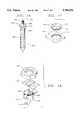
- the surgical implant system of the instant inventionis generally shown as numerated 10 for use in the stabilization of a human spine by fixation of vertebra.
- the construction materialsconsist of stainless steel, titanium, or the like high quality material.
- the base of the systememploys a spinal screw 12 shown diverging in the sacrum 14.
- the sacral screw 12characterized by a first end 16 having a relatively coarse self-tapping thread 18 over a major portion of its length.
- a second end 20having a first 22 and second 24 spaced apart protruding member extending obliquely from the screw defining an inner surface saddle 26 having an inner diameter corresponding to the outer diameter of a conventional support alignment rod 28.
- the screwcan be made of various lengths and diameters, the size dependant upon the location for placement, the amount of support or reconstruction required, and the actual size of the individual's bone structure.
- the outer surface of the second end 20 of the screw 12includes a plurality of grooves placed therein to form a partial thread 34.
- the threads 34can be cast or placed on the surface by means of a conventional thread shaping die.
- the saddle 26receptive to an alignment support rod 28 placed along the length of the vertebra 30 of the spine 32 to provide longitudinal support.
- a rectangular shaped rigid plate 36can then be used to connect two sagittal placed screws 12.
- the plate 36is defined as an elongated sagittal traverse support member having first 38 and second end 40 and two edges and upper and lower reversible surface.
- At the first end 36is placed an opening 42 operatively associated with the protruding members 22 and 24 of the screw 12.
- the first screwis rigidly connected to the second screw by placement of the plate 36 over the protruding members respectively.
- Openings 42are provided to accommodate the protruding members 22, 24 by use of two slots disposed at the first end 38 for insertion of the protruding members of the first screw and two slots 44 disposed in the second end 40 for insertion of the protruding members of the sagittal placed second screw.
- the connecting member 36is rigidly secured to the screws 12 by use of metal nuts 46 having an internal thread 48 engageable with the threaded surface 34 of each protruding member.
- a means for spacing the traverse support member a predetermined distance from the saddle surface 26is accomplished by use of a washer 50 having an elongated slot for disposition over the protruding members.
- the screwallowing for placement on a top surface of the alignment support rod 28 placed within the saddle 26.
- Rod supportcan also be accomplished by top loading, without a cross link, by use of the screw attachment 12 to the bone with a segmented slotted member 37 to fit directly over the protruding members of the screw.
- Securementis accomplished by the attachment nuts 46 to the screw 12 causing member 37 to fixate rod 28 in position.
- This embodimentis preferred for thoraco lumbar stabilization by use of linking the support alignment rods that are placed bilaterally.
- the use of additional screws, as shown,allow for support along the length of the vertebrae.
- the metal nuts 46threaded directly to the top of the screws 12 eliminating the need for movement of muscle during surgery.
- a variable angled cross-link sagittal traverse support memberhaving a first end 62 and a second end 64 and two edges 66 & 68 with an upper 70 and a lower 72 reversible surface.
- the first end 62includes a centrally disposed opening 74 available for insertion of a cylindrical post commonly used with pedicle screws of the prior art and the variable offset screw of the instant invention described later in this embodiment.
- a means for rotating 76the coupling slots in radial relation to the support member 60. The rotation allowing for the offset of a top loading screw by rotation member 76 permitting placement at variable directions for insertion of the protruding members through the slots 78.
- a rigid support member 80can be defined by a first end 82 and a second end 84 with two surfaces therebetween as shown in FIG. 3 wherein an elongated centrally disposed opening or slot 86 extends from the first end to the second end allowing a universally acceptable attachment means for pinon shafts or in the saddle post attachment by use of an enlarged slot.
- FIG. 4illustrates the use of a variable cross-link support member 90 having a first end 92 and a second end 94 with a first rotatable disk 96 for rotating at least two slots 98 in radial relation to the support member 90.
- a second rotatable disk 100 for rotating at least two slots 102 in radial relation to the support member 90is disposed at the second end.
- the disks 96 and 100are permanently secured to the support member 90 allowing freedom of circular rotation only. The freedom of rotation allows for correction of angle when the screws do not line up directly across the spine.
- the variable angled support member 90can be attached to the screw a first screw in the previously described manner by placement of the slots 98 over the protruding members 106 of the saddle end of the screw 104.
- a second screw 108can be placed sagittal across the spine but now in a dissimilar plane allowing a surgeon to custom place the screw 108 in the strongest area of the bone eliminating the need to bridge a damaged or degenerative area.
- the slots 102are placed over the protruding members 110 of the saddle end of the screw 108.
- the metal nuts 112are used for engagement with the outer surfaces 116 and 118 of the corresponding protruding members.
- the support member 90residing tightly against the alignment support rod 120 causing a frictional engagement with the inner surface of the saddle.
- the variable angled support memberis made of a variety of lengths for spanning any length range.
- a second support member 90is shown is a directly traversing manner wherein the rotatable disks 96 and 100 are placed in a conventional format for placement over the screws 104 and 108.
- the benefit of the rotatable diskis especially noticeable where the disk may need only a minute movement to accommodate the situation whereas the prior are would require screw removal and replacement.
- the systemincludes the flexibility to attach a cross-link without screw support yet employ the top loading benefit.
- a U-shaped saddle 91can be placed about the support rod 120 with a second sagittal placed saddle support 95 shown here in a four protruding member design.
- Variable cross-link support member 90with a first rotatable disk 97 for rotating at the four slots in radial relation to the support member 90.
- a second rotatable disk 100is placed at the opposite end for rotating at the two slots in radial relation to the support member 90.
- the freedom of rotationallows for correction of angle when the attachment devices 91 and 95 do not line up directly across the spine.
- the metal nuts 112engage the outer surfaces of the corresponding protruding members.
- the support member 90residing tightly against the alignment support rod 120 causing a frictional engagement with the inner surface of the saddle.
- FIGS. 5 and 6illustrate a perspective view of a caudal facing hook 130 having a hook shaped base 132 formed integral with a saddle shaped upper portion 134.
- the saddle shape portionillustrates the protruding member 136 and 138 common to the invention with the threads 140 cast into the outer surface of the members.
- the saddle in this type of hookallows for attachment directly onto an alignment support rod wherein the metal nut 142 includes internal threads 144 engageable directly with the hook body 130 threads 140 securely fastening the hook in position.
- various hook embodimentssuch as claw and fork hook which employ the top-loading threaded attachment of the instant invention.
- FIG. 7shown is an alternative embodiment of the screw attachment 150 having four spaced apart protruding members 152.
- Each protruding memberhaving a first side 154 surface and a second side 156 surface forming an arcuate shaped saddle 158.
- the third side surface 160 and fourth side surface 162are threaded for engagement with the inner threaded surface 164 of attachment nut 166.
- the saddle surfaceadapted for support of an alignment support rod in a longitudinal or perpendicular mode, the increased saddle surface area providing additional stability for use as a hook or the like attachment.
- Coupling an alignment support rod to the screw 150requires the use of a rectangular rigid plate 170 defined by four edges rounded at the corners with two side surfaces with four openings 172 placed therethrough at each end operatively associated with the four spaced apart protruding members of the attachment screw 150.
- the support memberallows for interconnecting to a second sagittal disposed and/or a bilaterally placed screw 174.
- the support member 170 for the four protruding membersmay also include a means for rotating the four openings 172 in radial relation to the support member 170 by use of a rotatable disk similar to that shown in FIG. 4 which is permanently secured to the support member 170 allowing freedom of circular rotation. The freedom of rotation allowing for correction of angle when the screws do not line up directly across the spine. Singular attachment plates may also be employed when cross-linking is not desired.
- variable directional attachment screw 180is shown defined by a first end 182 and a second end 184.
- the first end 182having a relatively coarse self-tapping thread 186 over a major portion of its length and a shoulder 188 having a plurality of ridges placed about the circumference.
- the second end 184utilizes a rectilinear protruding shaft 190 extending obliquely from the shoulder 188 having a threaded section 192 for use in conjunction with an attachment nut 194.
- the variable directional screw 182allows engagement of attachment member 196 having a first directional shaft 198 and base end 200 forming a shoulder.
- the base end 200includes a side surface 202 engageable with the shoulder ridges 188 of the screw allowing the base to index about the circumference of the shaft 190 for direction application of the shaft 198.
- the metal nut 194is used to engage the threads 192 of the protruding shaft fixing the directional shaft in a stationary position.
- an alternative base end 210is shown including a side surface 212 engageable with the shoulder ridges 188 of the screw 182 allowing the base to index about the circumference of the shaft 190 for direction application of a shaft 214.
- the metal nut 194is used to engage the threads 192 of the protruding shaft fixing the directional shaft in a stationary position.
- a second base member 216can then be added having a side surface 218 engageable with the shoulder ridges 220 located about shaft 214 allowing the second base 216 to index about the circumference of the shaft 214 for direction application of a shaft 222.
- the metal nut 224is used to engage the threads of the shaft 214 fixing the directional shaft in a stationary position.
- a third nutis made available to tightened to devices such as the plates disclosed in FIGS. 2 and 3 for pinion type shaft attachment.
- FIG. 10illustrates an alternative cross link based upon a C-shaped bracket 230 having two holes 232 and 234 with a peg 236 and nut 238 for locking the bracket 230 in position about a conventional alignment support rod 240.
- the cross-link 242can be placed through the pinion type peg 236 by use of attachment holes 244 for stabilizing along the bilateral support rod 240.
- the cross-link 242provides stability for a mid-thoracic and is less bulky that the aforementioned cross-links. Further shown is use of an improved alignment rod 240 having a plurality of spaced apart raised ridges 241 to assist in maintaining attachment-brackets in a predetermined position.
- FIG. 11is a anterior cervical plate employing a second plate for locking purposes.
- Cervical plate 250is defined as a first rectangular shaped rigid plate having a first end 252 and a second end 254 and two side edges 256 and 258 with a curvature formed between the two edges causing the plate 252 to have a slight curve in it for the cervical curve.
- the plateutilizes a plurality of openings such as the slots 260 and holes 262 for use in attaching the plate 250 to the cervical by use of conventional bone screws.
- a second rectangular shaped rigid plate 270defined by two ends 272 and 274 and two edges 276 and 278 also having a curvature between the two edges is used to couple to the first plate 250 to prevent the bone screws, not shown, from loosening out of the bone.
- One surface 280 of the placeincludes a series of indentations 282 and 284 to accommodate the bone screws head.
- the second plate 270has a plurality of attachment holes 286 placed about the outer edge of the plate 250 for insertion of threaded screws that which in turn can be threaded in coupling holes 288 placed about the circumference of the first plate 250.
- Cervical plate 250is readily attached to the spine 290 by use of screws 292 placed into the slots 260.
- the second plate 270is then placed over the cervical plate 250, the raised indentations 282 and 284 of the plate allowing a flush attachment.
- Attachment screws 294are placed through the openings 286 of the second plate and are threaded into threaded openings 288 of the first plate 250.
- the second plateessentially locking the first plate in position by preventing bone screws 292 from working their way out of the bone.
- FIG. 13is another embodiment of an anterior cervical plate employing a second plate for locking purposes.
- Cervical plate 300is defined as a first rectangular shaped rigid plate having a first end 302 and a second end 304 and two side edges 306 and 308 with a curvature formed between the two edges causing the plate 302 to have a slight curve in it for the cervical curve.
- the plateutilizes a plurality of openings such as the slots 310 and holes 312 for use in attaching the plate 300 to the cervical by use of conventional bone screws.
- attachment strap 314Permanently attached to each side of the plate is attachment strap 314 which includes a means for permanently attaching to strap 316.
- a second rectangular shaped rigid plate 320defined by two ends 322 and 324 and two edges 326 and 328 also having a curvature between the two edges is used to couple to the first plate 300 to prevent the bone screws, not shown, from loosening out of the bone.
- One surface of the placeincludes a series of indentations 330 to accommodate the bone screws head.
- the second plate 320has two coupling points 332 that are operatively associated with the aforementioned strapping means 314 and 316.
- the anterior cervical plateis shown attached in a locked position. Cervical plate 30 is readily attached to the spine by use of conventional bone screws placed.
- the second plate 320is then placed over the cervical plate 300, the raised indentations of the plate allowing a flush attachment.
- the attachment straps 314is then permanently affixed to the second plate 320 followed by attachment straps 316. The attachment straps permanently affixing the two plates in a juxtaposition.
- FIG. 15is still another embodiment of an anterior cervical plate employing a second plate for locking purposes.
- Cervical plate 350is defined as a first rectangular shaped rigid plate having a first raised end 352 and a second raised end 354 and two raised side edges 356 and 358 with a curvature formed between the two edges causing the plate 352 to have a slight curve in it for the cervical curve.
- the plateutilizes a plurality of openings such as the slots 360 for use in attaching the plate 350 to the cervical by use of conventional bone screws.
- This embodimentemploys a plurality of threaded bosses 362 permanently attached to the inner surface of the plate for second plate attachment purposes.
- a second rectangular shaped rigid plate 370defined by two ends 372 and 374 and two edges 376 and 378 also having a curvature between the two edges is used to couple to the first plate 350 to prevent the bone screws, not shown, from loosening out of the bone.
- the ends and edges fitting within the first plate 350assimilating a single piece anterior plate.
- One surface of the second placeincludes a series of indentations 384 to accommodate the bone screws head used in attaching the first plate to the bone.
- the second plate 370having a plurality of holes 380 to accommodate the bosses 362 wherein attachment nuts 382 permanently fasten the two plates in position.
- a post screw 390 for attachment to the pedicle boneis shown.
- a first end 392includes a relatively coarse self-tapping thread over a major portion of its length.
- a second end 394forming an enlarged shoulder 396 for bracket support or placement of spacing washers 398.
- the second endutilizes a rectilinear protruding shaft 400 extending obliquely from the shoulder 396 having a threaded section 404 for use in conjunction with an attachment nut. Installation can be performed by use of the centrally disposed slot 402 or a hex shaped shaft or shoulder.
- variable angled and adjustable cross-link sagittal traverse support member 410having a finely threaded aperture 414 for insertion of rotatable disk 412 having engagement threads 416.
- the diskallowing the surgeon to rotate the disk as well as provide a means for vertical adjustment in a manner similarly to the spacing washers.
- FIGS. 18provides a perspective view of an oversized caudal facing hook 430 having a hook shaped base 432 with a fork opening 440 formed integral with a saddle shaped upper portion 434.
- the saddle shape portionillustrates the enlarged protruding member necessary in instances of large bone attachment or the need of greater strength.
- the embodimentutilizes a form of four member protrusion with the U-shaped side surfaces thereby providing the additional support.
- the saddleallows for attachment directly onto an alignment support rod wherein the metal nut 446 includes internal threads engageable directly with the threaded hook body 436.
- the nut 446forcing the support plate 444 tightly against the alignment rod 442, the use of a beveled support plate is shown 444 which is preformed to accommodate the curvature of the rod thereby allowing an increase in the surface area of contact.
Landscapes
- Health & Medical Sciences (AREA)
- Orthopedic Medicine & Surgery (AREA)
- Life Sciences & Earth Sciences (AREA)
- Surgery (AREA)
- Neurology (AREA)
- Heart & Thoracic Surgery (AREA)
- Engineering & Computer Science (AREA)
- Biomedical Technology (AREA)
- Nuclear Medicine, Radiotherapy & Molecular Imaging (AREA)
- Medical Informatics (AREA)
- Molecular Biology (AREA)
- Animal Behavior & Ethology (AREA)
- General Health & Medical Sciences (AREA)
- Public Health (AREA)
- Veterinary Medicine (AREA)
- Surgical Instruments (AREA)
Abstract
Description
This application is a Continuation of Application Ser. No. 08/241,356,filed 05/11/94 now abandoned which is a division of Application Ser. No. 07/928,263, filed 8/11/92 now U.S. Pat. No. 5,397,363.
1. Field of the Invention
This invention relates generally to spinal implants and, in particular, to a spinal implant having a novel top-loading bolt attachment for support and alignment rods with cross links and ancillary components for stabilization of the vertebrae as well as a two plate system for cervical spine fixation.
2. Background of the Invention
Surgical implants are well known in the art for treatment of curvatures of the spine including anterior, trauma, deformity, and/or degenerative spinal conditions. The purpose of the implant is to reinforce the spine by use of strategically placed attachment screws capable of supporting alignment support rods placed bilateral along the vertebrae as well as cross-link members that bridge the sagittal of the spine.
The problem which this invention addresses is the method of fastening the spinal implants during surgery. Conventionally, the placement of an attachment screw provides the functional base for the support rod, cross-link, caudal facing hooks, cranial facing hook and the like components that form a spinal implant system. The conventional method of fastening utilizing a goal post mounting screw from which a bolt and nut is coupled perpendicular thereto for mounting to the component. This side attachment frequently requires the movement of muscle and other tissue during operation which increases the difficulty of the operation, is a time consuming effort, and can be a major trauma to a person.
In addition, the use of the prior art devices required pre-thought to where the cross-links are to be placed. Once the base screws are installed, they cannot be moved and if the screws are placed incorrectly, the cross-link will not fit.
U.S. Pat. No. 5,084,048, issued to Jacob et al., entitled "Implant for Vertebrae With Spinal Stabilizer" discloses a vertebrae implant having a stabilizing element which is articulated to accommodate a pair of bone screws wherein each bone screw includes a clamp disposed between a shoulder in a spherical surface which is all coupled together by the use of a clamping nut directly on the end of the bone screw. The device allows for support of an alignment rod along the side of the bone screw, but fails to provide any type of cross link or ancillary component attachment devices.
U.S. Pat. No. 4,041,939, issued to Hall, entitled "Surgical Implant Spinal Screw" discloses a spinal implant utilizing a screw having a centrally disposed aperture for placement of a metal cable therethrough with a nylon insert that will permanently secure the cable in a fixed position once attached. The device is best used in an operation for the correction of scoliosis.
Another problem with prior art is the use of anterior cervical plates. The prior art employs a single plate that is attached by the use of small bone attachment screws. After installation, the screws have a tendency of working their way out of the bone resulting in the loosening of the cervical plate causing the patient pain and typically resulting in further surgery to correct the problem.
Therefore there exists a need to correct the aforementioned problems by use of a top loading spinal implant system and associated cervical plate attachment cover.
The instant invention is a surgical implant system for the stabilization of the human spine by fixation of the vertebra. The system is based upon screws, nuts, rods, hooks, cross-members and variations thereof. The preferred embodiment employs a metal screw for placement in the sacrum or pedicle defined by a coarse self-tapping thread and a U-shaped saddle for placement of conventional alignment rods. Unique to this invention is that the screw is threaded on the outer surface of the saddle allowing the alignment rod to be securely fastened into the saddle by placement of the rod therein and the fastening of a nut to the top of saddle. Further unique to this invention is the use of an elongated sagittal traverse support member that can accommodate the saddle protrusion either in a fixed position or by use of a rotatable insert that allows the cross member to be tightly fastened to the saddle in a variable alignment. The top-loading attachment is further applicable to caudal, cranial, and the like hook components.
An anterior cervical plate is set forth using a second plate to permanently lock the cervical plate in position. The second plate does not rely upon the bone to support the plate thus providing a means to prevent any bone attachment screws from loosening or otherwise backing out of the bone.
Accordingly, an objective of the instant invention is to provide thoracic lumbar stabilization by use of linking conventional support alignment rods placed bilaterally along the vertebrae with the top-loading sacral and pedicle screws of the instant invention.
Still another objective is to lessen the need for ancillary tissue movement during surgery by use of a top mounted attachment means for ancillary components and provide a variable attachment system to provide the surgeon with fixation components that will accommodate a variety of circumstances.
Yet another objective of the instant invention is to provide a cross-link member that is operatively associated with the attachment screws by means of a top mounted link that is receptive to the protruding members of the screws or separate cross link attachments.
Yet still another objective of the instant invention is to provide a variable attachment means for two member and four member attachment screws by the use of rotatable attachment slots within the cross-link members.
Still another objective of the instant invention is to simplify the means for attaching caudal, thoracic, cranial and the like hooks by use of a top loading fastening nut that is threaded directly onto the hook body.
Still another objective of the instant invention is to provide an improved sacral and pedicle pinion post screw that allows angular bridging by use of an indexing right angled base having the means for coupling to another right angled base.
Yet still another objective is to disclose an improved anterior cervical plate having a second plate that couples to the cervical mounted plate effectively locking the cervical mounted plate in position by preventing the retraction of the mounting screws, while allowing the mounting screws to be put in at various angles and positions.
Other objects and advantages of this invention will become apparent from the following description taken in conjunction with the accompanying drawings wherein set forth, by way of illustration and example, certain embodiments of this invention. The drawings constitute a part of this specification and include exemplary embodiments of the instant invention and illustrate various objects and features thereof.
FIG. 1 is an exploded perspective view of the preferred embodiment of the instant invention;
FIG. 2 is perspective view of a variation to the cross-link member support;
FIG. 3 is perspective view of another variation to the cross-link member support by use of an elongated slot;
FIG. 4 is a perspective view of the spinal implant using employing the variable cross-link support member;
FIG. 5 is a perspective view of the bifurcated externally threaded hook attachment;
FIG. 6 is a perspective view of the attachment nut for use with the spinal screw of FIG. 5;
FIG. 7 is an exploded perspective view of a four protruding member spinal screw embodiment;
FIG. 8 is an exploded view of a pinion spinal screw with a first rotatable directional shaft;
FIG. 9 is an exploded view of a pinion spinal screw with a secondary rotatable direction shaft coupling to the first shaft of FIG. 8;
FIG. 10 is an exploded view of a bridge cross-link attachment member employing a C-shaped clamp with bolt and nut;
FIG. 11 is a top view of the anterior cervical plates;
FIG. 12 is a perspective view of the anterior cervical plates available for installation;
FIG. 13 is a top view of an anterior cervical plate using a strap embodiment;
FIG. 14 is a perspective view of the anterior cervical plates with the strap embodiment in an attached position;
FIG. 15 is a perspective view of another two plate anterior cervical plate with the strap embodiment in an attached position;
FIG. 16 is an exploded view of a pinion spinal screw with an enlarged shoulder;
FIG. 17 is a perspective view of a variation to the cross-link member support employing a threaded rotatable member; and
FIG. 18 is a perspective view of an enlarged bifurcated externally threaded hook attachment with a preformed support member.
As required, detailed embodiments of the present invention are disclosed herein, however, it is to be understood that the disclosed embodiments are merely exemplary of the invention which may be embodied in various forms. Therefore, specific functional and structural details disclosed herein are not to be interpreted as limiting, but merely as a basis for the claims and as a representative basis for teaching one skilled in the art to variously employ the present invention in virtually any appropriately detailed structure.
Now referring to FIG. 1, the surgical implant system of the instant invention is generally shown asnumerated 10 for use in the stabilization of a human spine by fixation of vertebra. The construction materials consist of stainless steel, titanium, or the like high quality material. The base of the system employs aspinal screw 12 shown diverging in thesacrum 14. Thesacral screw 12 characterized by afirst end 16 having a relatively coarse self-tappingthread 18 over a major portion of its length. Asecond end 20 having a first 22 and second 24 spaced apart protruding member extending obliquely from the screw defining aninner surface saddle 26 having an inner diameter corresponding to the outer diameter of a conventionalsupport alignment rod 28. The screw can be made of various lengths and diameters, the size dependant upon the location for placement, the amount of support or reconstruction required, and the actual size of the individual's bone structure. The outer surface of thesecond end 20 of thescrew 12 includes a plurality of grooves placed therein to form apartial thread 34. Thethreads 34 can be cast or placed on the surface by means of a conventional thread shaping die. Thesaddle 26 receptive to analignment support rod 28 placed along the length of thevertebra 30 of thespine 32 to provide longitudinal support.
A rectangular shapedrigid plate 36 can then be used to connect two sagittal placed screws 12. Theplate 36 is defined as an elongated sagittal traverse support member having first 38 andsecond end 40 and two edges and upper and lower reversible surface. At thefirst end 36 is placed anopening 42 operatively associated with the protrudingmembers screw 12. The first screw is rigidly connected to the second screw by placement of theplate 36 over the protruding members respectively.Openings 42 are provided to accommodate the protrudingmembers first end 38 for insertion of the protruding members of the first screw and twoslots 44 disposed in thesecond end 40 for insertion of the protruding members of the sagittal placed second screw. The connectingmember 36 is rigidly secured to thescrews 12 by use ofmetal nuts 46 having aninternal thread 48 engageable with the threadedsurface 34 of each protruding member.
A means for spacing the traverse support member a predetermined distance from thesaddle surface 26 is accomplished by use of awasher 50 having an elongated slot for disposition over the protruding members. The screw allowing for placement on a top surface of thealignment support rod 28 placed within thesaddle 26. Rod support can also be accomplished by top loading, without a cross link, by use of thescrew attachment 12 to the bone with a segmented slottedmember 37 to fit directly over the protruding members of the screw. Securement is accomplished by theattachment nuts 46 to thescrew 12 causingmember 37 to fixaterod 28 in position. This embodiment is preferred for thoraco lumbar stabilization by use of linking the support alignment rods that are placed bilaterally. The use of additional screws, as shown, allow for support along the length of the vertebrae. Themetal nuts 46 threaded directly to the top of thescrews 12 eliminating the need for movement of muscle during surgery.
Referring in general to FIGS. 2 and 3, a variable angled cross-link sagittal traverse support member is shown having afirst end 62 and asecond end 64 and twoedges 66 & 68 with an upper 70 and a lower 72 reversible surface. Thefirst end 62 includes a centrally disposedopening 74 available for insertion of a cylindrical post commonly used with pedicle screws of the prior art and the variable offset screw of the instant invention described later in this embodiment. At thesecond end 64 is placed a means for rotating 76 the coupling slots in radial relation to thesupport member 60. The rotation allowing for the offset of a top loading screw byrotation member 76 permitting placement at variable directions for insertion of the protruding members through theslots 78. Alternatively, arigid support member 80 can be defined by afirst end 82 and asecond end 84 with two surfaces therebetween as shown in FIG. 3 wherein an elongated centrally disposed opening orslot 86 extends from the first end to the second end allowing a universally acceptable attachment means for pinon shafts or in the saddle post attachment by use of an enlarged slot.
FIG. 4 illustrates the use of a variablecross-link support member 90 having afirst end 92 and asecond end 94 with a firstrotatable disk 96 for rotating at least twoslots 98 in radial relation to thesupport member 90. A secondrotatable disk 100 for rotating at least twoslots 102 in radial relation to thesupport member 90 is disposed at the second end. Thedisks support member 90 allowing freedom of circular rotation only. The freedom of rotation allows for correction of angle when the screws do not line up directly across the spine. The variableangled support member 90 can be attached to the screw a first screw in the previously described manner by placement of theslots 98 over the protrudingmembers 106 of the saddle end of thescrew 104. Asecond screw 108 can be placed sagittal across the spine but now in a dissimilar plane allowing a surgeon to custom place thescrew 108 in the strongest area of the bone eliminating the need to bridge a damaged or degenerative area. Theslots 102 are placed over the protrudingmembers 110 of the saddle end of thescrew 108. Themetal nuts 112 are used for engagement with theouter surfaces support member 90 residing tightly against thealignment support rod 120 causing a frictional engagement with the inner surface of the saddle. The variable angled support member is made of a variety of lengths for spanning any length range. As shown asecond support member 90 is shown is a directly traversing manner wherein therotatable disks screws
The system includes the flexibility to attach a cross-link without screw support yet employ the top loading benefit. In this embodiment aU-shaped saddle 91 can be placed about thesupport rod 120 with a second sagittal placedsaddle support 95 shown here in a four protruding member design. Variablecross-link support member 90 with a firstrotatable disk 97 for rotating at the four slots in radial relation to thesupport member 90. A secondrotatable disk 100 is placed at the opposite end for rotating at the two slots in radial relation to thesupport member 90. The freedom of rotation allows for correction of angle when theattachment devices metal nuts 112 engage the outer surfaces of the corresponding protruding members. Thesupport member 90 residing tightly against thealignment support rod 120 causing a frictional engagement with the inner surface of the saddle.
FIGS. 5 and 6 illustrate a perspective view of a caudal facinghook 130 having a hook shapedbase 132 formed integral with a saddle shapedupper portion 134. The saddle shape portion illustrates the protrudingmember threads 140 cast into the outer surface of the members. The saddle in this type of hook allows for attachment directly onto an alignment support rod wherein themetal nut 142 includesinternal threads 144 engageable directly with thehook body 130threads 140 securely fastening the hook in position. Although not shown, but deemed a part of this invention, is the use of various hook embodiments such as claw and fork hook which employ the top-loading threaded attachment of the instant invention. Unique to this invention is the ability to top-load the screw, attachment device, or hook member allowing the surgeon to perform all couplings from directly above the spine, as compared to the prior art requiring the attachment from the side. The importance of this factor cannot be emphasized enough, or illustrated by drawings, as the amount of muscle that encompasses the spinal area must be moved to accommodate the prior art attachment methods.
Now referring to FIG. 7, shown is an alternative embodiment of thescrew attachment 150 having four spaced apart protrudingmembers 152. Each protruding member having afirst side 154 surface and asecond side 156 surface forming an arcuate shapedsaddle 158. Thethird side surface 160 andfourth side surface 162 are threaded for engagement with the inner threadedsurface 164 ofattachment nut 166. The saddle surface adapted for support of an alignment support rod in a longitudinal or perpendicular mode, the increased saddle surface area providing additional stability for use as a hook or the like attachment. Coupling an alignment support rod to thescrew 150 requires the use of a rectangularrigid plate 170 defined by four edges rounded at the corners with two side surfaces with fouropenings 172 placed therethrough at each end operatively associated with the four spaced apart protruding members of theattachment screw 150. The support member allows for interconnecting to a second sagittal disposed and/or a bilaterally placedscrew 174. Thesupport member 170 for the four protruding members may also include a means for rotating the fouropenings 172 in radial relation to thesupport member 170 by use of a rotatable disk similar to that shown in FIG. 4 which is permanently secured to thesupport member 170 allowing freedom of circular rotation. The freedom of rotation allowing for correction of angle when the screws do not line up directly across the spine. Singular attachment plates may also be employed when cross-linking is not desired.
Referring now to FIGS. 8 and 9, a variabledirectional attachment screw 180 is shown defined by afirst end 182 and asecond end 184. Thefirst end 182 having a relatively coarse self-tappingthread 186 over a major portion of its length and ashoulder 188 having a plurality of ridges placed about the circumference. Thesecond end 184 utilizes a rectilinearprotruding shaft 190 extending obliquely from theshoulder 188 having a threadedsection 192 for use in conjunction with anattachment nut 194. The variabledirectional screw 182 allows engagement ofattachment member 196 having a firstdirectional shaft 198 andbase end 200 forming a shoulder. Thebase end 200 includes aside surface 202 engageable with theshoulder ridges 188 of the screw allowing the base to index about the circumference of theshaft 190 for direction application of theshaft 198. Once a directional locale is depicted, themetal nut 194 is used to engage thethreads 192 of the protruding shaft fixing the directional shaft in a stationary position.
As shown in FIG. 9, analternative base end 210 is shown including aside surface 212 engageable with theshoulder ridges 188 of thescrew 182 allowing the base to index about the circumference of theshaft 190 for direction application of ashaft 214. Once a directional locale is depicted, themetal nut 194 is used to engage thethreads 192 of the protruding shaft fixing the directional shaft in a stationary position. Asecond base member 216 can then be added having aside surface 218 engageable with theshoulder ridges 220 located aboutshaft 214 allowing thesecond base 216 to index about the circumference of theshaft 214 for direction application of ashaft 222. Once a directional locale is depicted, themetal nut 224 is used to engage the threads of theshaft 214 fixing the directional shaft in a stationary position. A third nut is made available to tightened to devices such as the plates disclosed in FIGS. 2 and 3 for pinion type shaft attachment.
FIG. 10 illustrates an alternative cross link based upon a C-shapedbracket 230 having twoholes peg 236 andnut 238 for locking thebracket 230 in position about a conventionalalignment support rod 240. The cross-link 242 can be placed through thepinion type peg 236 by use of attachment holes 244 for stabilizing along thebilateral support rod 240. Thecross-link 242 provides stability for a mid-thoracic and is less bulky that the aforementioned cross-links. Further shown is use of animproved alignment rod 240 having a plurality of spaced apart raisedridges 241 to assist in maintaining attachment-brackets in a predetermined position.
FIG. 11 is a anterior cervical plate employing a second plate for locking purposes.Cervical plate 250 is defined as a first rectangular shaped rigid plate having afirst end 252 and asecond end 254 and twoside edges plate 252 to have a slight curve in it for the cervical curve. The plate utilizes a plurality of openings such as theslots 260 and holes 262 for use in attaching theplate 250 to the cervical by use of conventional bone screws. A second rectangular shapedrigid plate 270 defined by twoends edges first plate 250 to prevent the bone screws, not shown, from loosening out of the bone. Onesurface 280 of the place includes a series ofindentations second plate 270 has a plurality of attachment holes 286 placed about the outer edge of theplate 250 for insertion of threaded screws that which in turn can be threaded incoupling holes 288 placed about the circumference of thefirst plate 250.
As shown in FIG. 12 is a anterior cervical plate employing a second plate for locking purposes.Cervical plate 250 is readily attached to thespine 290 by use ofscrews 292 placed into theslots 260. Thesecond plate 270 is then placed over thecervical plate 250, the raisedindentations openings 286 of the second plate and are threaded into threadedopenings 288 of thefirst plate 250. The second plate essentially locking the first plate in position by preventingbone screws 292 from working their way out of the bone.
FIG. 13 is another embodiment of an anterior cervical plate employing a second plate for locking purposes.Cervical plate 300 is defined as a first rectangular shaped rigid plate having afirst end 302 and asecond end 304 and twoside edges 306 and 308 with a curvature formed between the two edges causing theplate 302 to have a slight curve in it for the cervical curve. The plate utilizes a plurality of openings such as theslots 310 andholes 312 for use in attaching theplate 300 to the cervical by use of conventional bone screws. Permanently attached to each side of the plate isattachment strap 314 which includes a means for permanently attaching to strap 316.
A second rectangular shapedrigid plate 320 defined by twoends edges first plate 300 to prevent the bone screws, not shown, from loosening out of the bone. One surface of the place includes a series ofindentations 330 to accommodate the bone screws head. Thesecond plate 320 has twocoupling points 332 that are operatively associated with the aforementioned strapping means 314 and 316.
As shown in FIG. 14 the anterior cervical plate is shown attached in a locked position.Cervical plate 30 is readily attached to the spine by use of conventional bone screws placed. Thesecond plate 320 is then placed over thecervical plate 300, the raised indentations of the plate allowing a flush attachment. The attachment straps 314 is then permanently affixed to thesecond plate 320 followed by attachment straps 316. The attachment straps permanently affixing the two plates in a juxtaposition.
FIG. 15 is still another embodiment of an anterior cervical plate employing a second plate for locking purposes.Cervical plate 350 is defined as a first rectangular shaped rigid plate having a first raisedend 352 and a second raisedend 354 and two raisedside edges plate 352 to have a slight curve in it for the cervical curve. The plate utilizes a plurality of openings such as theslots 360 for use in attaching theplate 350 to the cervical by use of conventional bone screws. This embodiment employs a plurality of threadedbosses 362 permanently attached to the inner surface of the plate for second plate attachment purposes.
A second rectangular shapedrigid plate 370 defined by twoends edges first plate 350 to prevent the bone screws, not shown, from loosening out of the bone. The ends and edges fitting within thefirst plate 350 assimilating a single piece anterior plate. One surface of the second place includes a series ofindentations 384 to accommodate the bone screws head used in attaching the first plate to the bone. Thesecond plate 370 having a plurality ofholes 380 to accommodate thebosses 362 whereinattachment nuts 382 permanently fasten the two plates in position.
Referring now to FIG. 16, apost screw 390 for attachment to the pedicle bone is shown. Afirst end 392 includes a relatively coarse self-tapping thread over a major portion of its length. Asecond end 394 forming anenlarged shoulder 396 for bracket support or placement ofspacing washers 398. The second end utilizes a rectilinearprotruding shaft 400 extending obliquely from theshoulder 396 having a threadedsection 404 for use in conjunction with an attachment nut. Installation can be performed by use of the centrally disposedslot 402 or a hex shaped shaft or shoulder.
Referring to FIG. 17, a variable angled and adjustable cross-link sagittal traverse support member 410 is shown having a finely threadedaperture 414 for insertion ofrotatable disk 412 havingengagement threads 416. The disk allowing the surgeon to rotate the disk as well as provide a means for vertical adjustment in a manner similarly to the spacing washers.
FIGS. 18 provides a perspective view of an oversized caudal facinghook 430 having a hook shapedbase 432 with afork opening 440 formed integral with a saddle shapedupper portion 434. The saddle shape portion illustrates the enlarged protruding member necessary in instances of large bone attachment or the need of greater strength. The embodiment utilizes a form of four member protrusion with the U-shaped side surfaces thereby providing the additional support. The saddle allows for attachment directly onto an alignment support rod wherein themetal nut 446 includes internal threads engageable directly with the threadedhook body 436. Thenut 446 forcing thesupport plate 444 tightly against thealignment rod 442, the use of a beveled support plate is shown 444 which is preformed to accommodate the curvature of the rod thereby allowing an increase in the surface area of contact.
It is to be understood that while we have illustrated and described certain forms of our invention, it is not to be limited to the specific forms or arrangement of components herein described and shown. It will be apparent to those skilled in the art that various changes may be made without departing from the scope of the invention and the invention is not to be considered limited to what is shown in the drawings and described in the specification.
Claims (3)
1. A surgical implant system for the anterior cervical comprising:
a support base formed by a first rectangular plate of nominal thickness defined by an upper surface and a lower surface having a length formed by a first and second end and a width, said width formed by a first side edge and a second side edge spanning the width of a human spinal column of a human, said plate curved between said first side edge and said second side edge by raising said first and second end of said plate a predetermined distance about each said side edge, said first plate having a plurality of slots formed therethrough each adapted to accommodate a screw shank of a bone screw for securing said first plate directly to a portion of a human's anterior cervical;
a lock cover formed by a second curved rectangular plate of nominal thickness having a top surface and a bottom surface with a width and length equal to said first plate, said second plate having indentations positioned over each slot of said first plate adapted to accommodate an upper portion of said bone screw; and
at least one attachment strap means permanently secured to said second surface of said first plate, said strap adapted for placement over said top surface of said second plate, said strap including a means for securing said second plate to said first plate;
whereby said support base is adapted to be secured to the anterior cervical of a human by use of bone screws, each bone screw having a shank placed through one of said first plate slots, said second plate being coupled to said first plate whereby said indentations in said second plate frictionally secure the screw heads between said upper surface of said support base and said bottom surface of said second plate to prevent said bone screws from rotation and thus loosening from the cervical.
2. The surgical implant system of claim 1, wherein said attachment strap means is further defined as a first attachment strap permanently secured to a side edge of said first plate and a second attachment strap permanently secured to an opposite side edge of said first plate, said first attachment strap having a means for coupling to said second attachment strap, whereby the bottom surface of said second plate is placed over the upper surface of said first place with said attachment straps wrapped around said second plate for securing to said first plate.
3. The surgical implant apparatus for stabilizing a portion of a human spine, said apparatus comprising:
a curved support plate of nominal thickness defined by an upper surface and a lower surface having a length and a width, said width bordered by a first side edge and a second side edge dimensioned and sized to span a spinal column of a human, said support plate having a plurality of spaced apart longitudinal attachment slots formed therethrough, said support plate having at least one attachment strap coupled to a first side edge of said support plate and at least one attachment strap coupled to an opposite side edge of said support plate, said first attachment strap having a means for coupling to said second attachment strap;
a lock plate of nominal thickness having a top surface and a bottom surface with a width and length and curvature equal to said support plate, said lock plate having raised indentations positioned over each slot of said support plate adapted to accommodate the head of a bone screw; and
whereby said support plate is aligned over a spinal column having properly positioned spinal elements and anchored thereto by use of bone screws inserted through said attachment slots, said lock plate being coupled to said support plate by wrapping said first and second attachment strap around said lock plate and coupling said straps together whereby said indentations in said lock plate frictionally secure the screw heads of bone screws between said upper surface of said support plate and said bottom surface of said lock plate to prevent the bone screws from rotating and loosening from the anchored position.
Priority Applications (1)
| Application Number | Priority Date | Filing Date | Title |
|---|---|---|---|
| US08/692,849US5766254A (en) | 1992-08-11 | 1996-07-24 | Spinal stabilization implant system |
Applications Claiming Priority (4)
| Application Number | Priority Date | Filing Date | Title |
|---|---|---|---|
| US07/928,263US5397363A (en) | 1992-08-11 | 1992-08-11 | Spinal stabilization implant system |
| US24135694A | 1994-05-11 | 1994-05-11 | |
| PCT/US1995/003331WO1996028106A1 (en) | 1992-08-11 | 1995-03-13 | Spinal stabilization implant system |
| US08/692,849US5766254A (en) | 1992-08-11 | 1996-07-24 | Spinal stabilization implant system |
Related Parent Applications (1)
| Application Number | Title | Priority Date | Filing Date |
|---|---|---|---|
| US24135694AContinuation | 1992-08-11 | 1994-05-11 |
Publications (1)
| Publication Number | Publication Date |
|---|---|
| US5766254Atrue US5766254A (en) | 1998-06-16 |
Family
ID=26789555
Family Applications (2)
| Application Number | Title | Priority Date | Filing Date |
|---|---|---|---|
| US07/928,263Expired - LifetimeUS5397363A (en) | 1992-08-11 | 1992-08-11 | Spinal stabilization implant system |
| US08/692,849Expired - LifetimeUS5766254A (en) | 1992-08-11 | 1996-07-24 | Spinal stabilization implant system |
Family Applications Before (1)
| Application Number | Title | Priority Date | Filing Date |
|---|---|---|---|
| US07/928,263Expired - LifetimeUS5397363A (en) | 1992-08-11 | 1992-08-11 | Spinal stabilization implant system |
Country Status (2)
| Country | Link |
|---|---|
| US (2) | US5397363A (en) |
| WO (1) | WO1996028106A1 (en) |
Cited By (101)
| Publication number | Priority date | Publication date | Assignee | Title |
|---|---|---|---|---|
| WO2000053077A2 (en) | 1999-03-07 | 2000-09-14 | Discure Ltd. | Method and apparatus for computerized surgery |
| US6183478B1 (en) | 1999-02-04 | 2001-02-06 | Depuy Orthopaedics, Inc. | Temporary fixation device |
| WO2001017465A1 (en)* | 1999-09-03 | 2001-03-15 | Cook Daniel J | Temporary spine fixation device and method |
| US6224602B1 (en) | 1999-10-11 | 2001-05-01 | Interpore Cross International | Bone stabilization plate with a secured-locking mechanism for cervical fixation |
| US6309391B1 (en) | 2000-03-15 | 2001-10-30 | Sdgi Holding, Inc. | Multidirectional pivoting bone screw and fixation system |
| US6312431B1 (en) | 2000-04-24 | 2001-11-06 | Wilson T. Asfora | Vertebrae linking system |
| US20010038620A1 (en)* | 1999-05-21 | 2001-11-08 | Ensemble Communication Inc. | Method and apparatus for allocating bandwidth in a wireless communication system |
| US20020120273A1 (en)* | 1999-10-13 | 2002-08-29 | Needham Dusty Anna | Anterior cervical plating system and method |
| US20020128655A1 (en)* | 1997-02-11 | 2002-09-12 | Michelson Gary K. | Segmentable skeletal plating system |
| WO2002080789A1 (en)* | 2001-04-05 | 2002-10-17 | Osteotech, Inc. | Bone fixation system and method |
| US20020183757A1 (en)* | 2001-06-04 | 2002-12-05 | Michelson Gary K. | Dynamic single-lock anterior cervical plate system having non-detachably fastened and moveable segments, instrumentation, and method for installation thereof |
| US20020183754A1 (en)* | 2001-06-04 | 2002-12-05 | Michelson Gary K. | Anterior cervical plate system having vertebral body engaging anchors, connecting plate, and method for installation thereof |
| US20020183755A1 (en)* | 2001-06-04 | 2002-12-05 | Michelson Gary K. | Dynamic anterior cervical plate system having moveable segments, instrumentation, and method for installation thereof |
| US20020188296A1 (en)* | 2001-06-06 | 2002-12-12 | Michelson Gary K. | Dynamic, modular, multilock anterior cervical plate system having detachably fastened assembleable and moveable segments, instrumentation, and method for installation thereof |
| US20030018335A1 (en)* | 1997-02-11 | 2003-01-23 | Michelson Gary K. | Anterior cervical plate system |
| US20030060828A1 (en)* | 2001-06-06 | 2003-03-27 | Michelson Gary K. | Dynamic multilock anterior cervical plate system having non-detachably fastened and moveable segments, instrumentation, and method for installation thereof |
| US20030105460A1 (en)* | 2000-03-15 | 2003-06-05 | Dennis Crandall | Multidirectional pivoting bone screw and fixation system |
| US6626909B2 (en)* | 2002-02-27 | 2003-09-30 | Kingsley Richard Chin | Apparatus and method for spine fixation |
| US6679883B2 (en) | 2001-10-31 | 2004-01-20 | Ortho Development Corporation | Cervical plate for stabilizing the human spine |
| US6682532B2 (en) | 2002-03-22 | 2004-01-27 | Depuy Acromed, Inc. | Coupling system and method for extending spinal instrumentation |
| US20040034356A1 (en)* | 2002-07-16 | 2004-02-19 | Lehuec Jean-Charles | Plating system for stabilizing a bony segment |
| US20040034353A1 (en)* | 1994-03-28 | 2004-02-19 | Michelson Gary Karlin | Apparatus and method for anterior spinal stabilization |
| US20040158246A1 (en)* | 1998-04-30 | 2004-08-12 | Sofamor S.N.C. | Anterior implant for the spine |
| US6776781B1 (en) | 2000-09-28 | 2004-08-17 | Farihan Renno | Spinal-column buttress plate assembly and method for attachment |
| US20040181226A1 (en)* | 2001-06-04 | 2004-09-16 | Michelson Gary K. | Method for installing dynamic, modular, single-lock anterior cervical plate system having assembleable and moveable segments |
| US20040220571A1 (en)* | 1998-04-30 | 2004-11-04 | Richard Assaker | Bone plate assembly |
| US20050277920A1 (en)* | 2004-05-28 | 2005-12-15 | Slivka Michael A | Non-fusion spinal correction systems and methods |
| US20050283155A1 (en)* | 2004-06-21 | 2005-12-22 | Michael Jacene | Instruments and methods for holding a bone plate |
| US20060036250A1 (en)* | 2004-08-12 | 2006-02-16 | Lange Eric C | Antero-lateral plating systems for spinal stabilization |
| US20060149255A1 (en)* | 2005-01-06 | 2006-07-06 | Doubler Robert L | Spinal implant kit |
| US20060155296A1 (en)* | 2005-01-07 | 2006-07-13 | Celonova Biosciences, Inc. | Three-dimensional implantable bone support |
| US20060195089A1 (en)* | 2005-02-03 | 2006-08-31 | Lehuec Jean-Charles | Spinal plating and intervertebral support systems and methods |
| US20060217721A1 (en)* | 2005-03-11 | 2006-09-28 | Suh Sean S | Translational hinged door plate system |
| US20060217713A1 (en)* | 2005-03-24 | 2006-09-28 | Serhan Hassan A | Low profile spinal tethering devices |
| US20060241615A1 (en)* | 2005-04-19 | 2006-10-26 | Sdgi Holdings, Inc. | Antero-lateral plating systems and methods for spinal stabilization |
| US20060265069A1 (en)* | 2000-12-13 | 2006-11-23 | Goble E M | Multiple Facet Joint Replacement |
| US20060271052A1 (en)* | 2005-05-12 | 2006-11-30 | Stern Joseph D | Revisable anterior cervical plating system |
| US20060293670A1 (en)* | 2005-06-03 | 2006-12-28 | Smisson Hugh F Iii | Surgical stabilization system |
| US20070173840A1 (en)* | 2006-01-11 | 2007-07-26 | Huebner Randall J | Bone plate with cover |
| US20070233184A1 (en)* | 2006-02-28 | 2007-10-04 | Klein Tools, Inc. | Medical instrument for grasping surgical implant rods |
| US7288095B2 (en) | 2004-08-12 | 2007-10-30 | Atlas Spine, Inc. | Bone plate with screw lock |
| US20070270820A1 (en)* | 2006-04-26 | 2007-11-22 | Sdgi Holdings, Inc. | Revision fixation plate and method of use |
| US7322984B2 (en) | 2005-01-06 | 2008-01-29 | Spinal, Llc | Spinal plate with internal screw locks |
| US7344539B2 (en) | 2001-03-30 | 2008-03-18 | Depuy Acromed, Inc. | Intervertebral connection system |
| WO2008112831A1 (en)* | 2007-03-12 | 2008-09-18 | Arya Nick Shamie | Improved cervical support system |
| US7468069B2 (en) | 2004-02-10 | 2008-12-23 | Atlas Spine, Inc. | Static anterior cervical plate |
| US7635380B2 (en) | 2007-06-05 | 2009-12-22 | Spartek Medical, Inc. | Bone anchor with a compressor element for receiving a rod for a dynamic stabilization and motion preservation spinal implantation system and method |
| US20090326590A1 (en)* | 1999-10-13 | 2009-12-31 | Warsaw Orthopedic, Inc. | System and method for securing a plate to the spinal column |
| US7682392B2 (en) | 2002-10-30 | 2010-03-23 | Depuy Spine, Inc. | Regenerative implants for stabilizing the spine and devices for attachment of said implants |
| US20100082067A1 (en)* | 2008-09-29 | 2010-04-01 | Kondrashov Dimitriy G | System and method to stablize a spinal column including a spinolaminar locking plate |
| US7727266B2 (en) | 2004-06-17 | 2010-06-01 | Warsaw Orthopedic, Inc. | Method and apparatus for retaining screws in a plate |
| US7736380B2 (en) | 2004-12-21 | 2010-06-15 | Rhausler, Inc. | Cervical plate system |
| US7740649B2 (en) | 2004-02-26 | 2010-06-22 | Pioneer Surgical Technology, Inc. | Bone plate system and methods |
| US7766947B2 (en) | 2001-10-31 | 2010-08-03 | Ortho Development Corporation | Cervical plate for stabilizing the human spine |
| US7766940B2 (en) | 2004-12-30 | 2010-08-03 | Depuy Spine, Inc. | Posterior stabilization system |
| US7799054B2 (en) | 2004-12-30 | 2010-09-21 | Depuy Spine, Inc. | Facet joint replacement |
| US7963978B2 (en) | 2007-06-05 | 2011-06-21 | Spartek Medical, Inc. | Method for implanting a deflection rod system and customizing the deflection rod system for a particular patient need for dynamic stabilization and motion preservation spinal implantation system |
| US7985244B2 (en) | 2004-09-30 | 2011-07-26 | Depuy Spine, Inc. | Posterior dynamic stabilizer devices |
| US20110190776A1 (en)* | 2009-12-18 | 2011-08-04 | Palmaz Scientific, Inc. | Interosteal and intramedullary implants and method of implanting same |
| US7993372B2 (en) | 2007-06-05 | 2011-08-09 | Spartek Medical, Inc. | Dynamic stabilization and motion preservation spinal implantation system with a shielded deflection rod system and method |
| US8007518B2 (en) | 2008-02-26 | 2011-08-30 | Spartek Medical, Inc. | Load-sharing component having a deflectable post and method for dynamic stabilization of the spine |
| US8012181B2 (en) | 2008-02-26 | 2011-09-06 | Spartek Medical, Inc. | Modular in-line deflection rod and bone anchor system and method for dynamic stabilization of the spine |
| US8016861B2 (en) | 2008-02-26 | 2011-09-13 | Spartek Medical, Inc. | Versatile polyaxial connector assembly and method for dynamic stabilization of the spine |
| US8021396B2 (en) | 2007-06-05 | 2011-09-20 | Spartek Medical, Inc. | Configurable dynamic spinal rod and method for dynamic stabilization of the spine |
| US8043337B2 (en) | 2006-06-14 | 2011-10-25 | Spartek Medical, Inc. | Implant system and method to treat degenerative disorders of the spine |
| US8048115B2 (en) | 2007-06-05 | 2011-11-01 | Spartek Medical, Inc. | Surgical tool and method for implantation of a dynamic bone anchor |
| US8057517B2 (en) | 2008-02-26 | 2011-11-15 | Spartek Medical, Inc. | Load-sharing component having a deflectable post and centering spring and method for dynamic stabilization of the spine |
| US8070749B2 (en) | 2005-05-12 | 2011-12-06 | Stern Joseph D | Revisable anterior cervical plating system |
| US8083772B2 (en) | 2007-06-05 | 2011-12-27 | Spartek Medical, Inc. | Dynamic spinal rod assembly and method for dynamic stabilization of the spine |
| US8083775B2 (en) | 2008-02-26 | 2011-12-27 | Spartek Medical, Inc. | Load-sharing bone anchor having a natural center of rotation and method for dynamic stabilization of the spine |
| US8092496B2 (en) | 2004-09-30 | 2012-01-10 | Depuy Spine, Inc. | Methods and devices for posterior stabilization |
| US8092501B2 (en) | 2007-06-05 | 2012-01-10 | Spartek Medical, Inc. | Dynamic spinal rod and method for dynamic stabilization of the spine |
| US8097024B2 (en) | 2008-02-26 | 2012-01-17 | Spartek Medical, Inc. | Load-sharing bone anchor having a deflectable post and method for stabilization of the spine |
| US8114134B2 (en) | 2007-06-05 | 2012-02-14 | Spartek Medical, Inc. | Spinal prosthesis having a three bar linkage for motion preservation and dynamic stabilization of the spine |
| US8172885B2 (en) | 2003-02-05 | 2012-05-08 | Pioneer Surgical Technology, Inc. | Bone plate system |
| US8211155B2 (en) | 2008-02-26 | 2012-07-03 | Spartek Medical, Inc. | Load-sharing bone anchor having a durable compliant member and method for dynamic stabilization of the spine |
| US8257397B2 (en) | 2009-12-02 | 2012-09-04 | Spartek Medical, Inc. | Low profile spinal prosthesis incorporating a bone anchor having a deflectable post and a compound spinal rod |
| US8267979B2 (en) | 2008-02-26 | 2012-09-18 | Spartek Medical, Inc. | Load-sharing bone anchor having a deflectable post and axial spring and method for dynamic stabilization of the spine |
| US8333792B2 (en) | 2008-02-26 | 2012-12-18 | Spartek Medical, Inc. | Load-sharing bone anchor having a deflectable post and method for dynamic stabilization of the spine |
| US8337536B2 (en) | 2008-02-26 | 2012-12-25 | Spartek Medical, Inc. | Load-sharing bone anchor having a deflectable post with a compliant ring and method for stabilization of the spine |
| US8361126B2 (en) | 2007-07-03 | 2013-01-29 | Pioneer Surgical Technology, Inc. | Bone plate system |
| US8430916B1 (en) | 2012-02-07 | 2013-04-30 | Spartek Medical, Inc. | Spinal rod connectors, methods of use, and spinal prosthesis incorporating spinal rod connectors |
| US8518085B2 (en) | 2010-06-10 | 2013-08-27 | Spartek Medical, Inc. | Adaptive spinal rod and methods for stabilization of the spine |
| US8562656B2 (en) | 2010-10-15 | 2013-10-22 | Warsaw Orrthopedic, Inc. | Retaining mechanism |
| US8623019B2 (en) | 2007-07-03 | 2014-01-07 | Pioneer Surgical Technology, Inc. | Bone plate system |
| US8668725B2 (en) | 2007-07-13 | 2014-03-11 | Southern Spine, Llc | Bone screw |
| US8900277B2 (en) | 2004-02-26 | 2014-12-02 | Pioneer Surgical Technology, Inc. | Bone plate system |
| US8992579B1 (en) | 2011-03-08 | 2015-03-31 | Nuvasive, Inc. | Lateral fixation constructs and related methods |
| US9011540B1 (en)* | 2005-03-24 | 2015-04-21 | Igip, Llc | Overlay or implant and method for improving stability of the implant |
| US9028549B1 (en)* | 2008-03-27 | 2015-05-12 | Spinelogik, Inc. | Intervertebral fusion device and method of use |
| US9060815B1 (en) | 2012-03-08 | 2015-06-23 | Nuvasive, Inc. | Systems and methods for performing spine surgery |
| US9095444B2 (en) | 2009-07-24 | 2015-08-04 | Warsaw Orthopedic, Inc. | Implant with an interference fit fastener |
| US9271742B2 (en) | 2012-08-09 | 2016-03-01 | Wilson Theophilo Asfora | System for joint fusion |
| US9427324B1 (en) | 2010-02-22 | 2016-08-30 | Spinelogik, Inc. | Intervertebral fusion device and method of use |
| US9468479B2 (en) | 2013-09-06 | 2016-10-18 | Cardinal Health 247, Inc. | Bone plate |
| US9517089B1 (en) | 2013-10-08 | 2016-12-13 | Nuvasive, Inc. | Bone anchor with offset rod connector |
| US9526533B1 (en)* | 2014-09-12 | 2016-12-27 | Roberto J. Aranibar | Spinal repair implants and related methods |
| USD779065S1 (en) | 2014-10-08 | 2017-02-14 | Nuvasive, Inc. | Anterior cervical bone plate |
| CN107411854A (en)* | 2017-07-12 | 2017-12-01 | 中南大学湘雅医院 | Practical artificial vertebral plate device |
| CN109567918A (en)* | 2018-11-27 | 2019-04-05 | 中南大学湘雅医院 | Medical titanium alloy conical plate positioning system |
| US11877779B2 (en) | 2020-03-26 | 2024-01-23 | Xtant Medical Holdings, Inc. | Bone plate system |
Families Citing this family (142)
| Publication number | Priority date | Publication date | Assignee | Title |
|---|---|---|---|---|
| FR2718943B1 (en)* | 1994-04-21 | 1996-06-21 | Jbs Sa | Reinforced bar with three branches for osteosynthesis of the spine. |
| US5716355A (en)* | 1995-04-10 | 1998-02-10 | Sofamor Danek Group, Inc. | Transverse connection for spinal rods |
| FR2738143B1 (en)* | 1995-09-04 | 1997-10-10 | Cahlik Marc Andre | INTERVERTEBRAL STABILIZATION SURGICAL IMPLANT |
| FR2738144B1 (en)* | 1995-09-04 | 1997-10-10 | Cahlik Marc Andre | VERSATILE INTERVERTEBRAL STABILIZATION DEVICE |
| EP0873090A1 (en)* | 1995-12-22 | 1998-10-28 | Ohio Medical Instrument Company, Inc. | Spinal fixation device with laterally attachable connectors |
| ZA983955B (en)* | 1997-05-15 | 2001-08-13 | Sdgi Holdings Inc | Anterior cervical plating system. |
| US5980523A (en)* | 1998-01-08 | 1999-11-09 | Jackson; Roger | Transverse connectors for spinal rods |
| DE19816782A1 (en)* | 1998-04-16 | 1999-10-28 | Ulrich Gmbh & Co Kg | Implant for insertion between the vertebral body of the spine |
| US6251140B1 (en) | 1998-05-27 | 2001-06-26 | Nuvasive, Inc. | Interlocking spinal inserts |
| US6368325B1 (en) | 1998-05-27 | 2002-04-09 | Nuvasive, Inc. | Bone blocks and methods for inserting bone blocks into intervertebral spaces |
| US6290724B1 (en) | 1998-05-27 | 2001-09-18 | Nuvasive, Inc. | Methods for separating and stabilizing adjacent vertebrae |
| US6264658B1 (en) | 1998-07-06 | 2001-07-24 | Solco Surgical Instruments Co., Ltd. | Spine fixing apparatus |
| US6234705B1 (en) | 1999-04-06 | 2001-05-22 | Synthes (Usa) | Transconnector for coupling spinal rods |
| US6283967B1 (en) | 1999-12-17 | 2001-09-04 | Synthes (U.S.A.) | Transconnector for coupling spinal rods |
| US20020133155A1 (en)* | 2000-02-25 | 2002-09-19 | Ferree Bret A. | Cross-coupled vertebral stabilizers incorporating spinal motion restriction |
| US6964667B2 (en)* | 2000-06-23 | 2005-11-15 | Sdgi Holdings, Inc. | Formed in place fixation system with thermal acceleration |
| US6749614B2 (en)* | 2000-06-23 | 2004-06-15 | Vertelink Corporation | Formable orthopedic fixation system with cross linking |
| EP1292239B1 (en)* | 2000-06-23 | 2013-02-13 | University Of Southern California | Percutaneous vertebral fusion system |
| US6875212B2 (en)* | 2000-06-23 | 2005-04-05 | Vertelink Corporation | Curable media for implantable medical device |
| US6899713B2 (en)* | 2000-06-23 | 2005-05-31 | Vertelink Corporation | Formable orthopedic fixation system |
| US6852126B2 (en)* | 2000-07-17 | 2005-02-08 | Nuvasive, Inc. | Stackable interlocking intervertebral support system |
| US6740088B1 (en) | 2000-10-25 | 2004-05-25 | Sdgi Holdings, Inc. | Anterior lumbar plate and method |
| DE10101478C2 (en)* | 2001-01-12 | 2003-03-27 | Biedermann Motech Gmbh | connecting element |
| GB2371344A (en)* | 2001-01-23 | 2002-07-24 | Frederick Arthur Summerlin | Blind rivet |
| KR100397128B1 (en)* | 2001-03-21 | 2003-09-17 | 정연문 | Apparatus for fixation of cervical spine |
| FR2823096B1 (en)* | 2001-04-06 | 2004-03-19 | Materiel Orthopedique En Abreg | PLATE FOR LTE AND LTE VERTEBRATE OSTEOSYNTHESIS DEVICE, OSTEOSYNTHESIS DEVICE INCLUDING SUCH A PLATE, AND INSTRUMENT FOR LAYING SUCH A PLATE |
| FR2829919B1 (en)* | 2001-09-26 | 2003-12-19 | Spine Next Sa | VERTEBRAL FIXATION DEVICE |
| US6923814B1 (en) | 2001-10-30 | 2005-08-02 | Nuvasive, Inc. | System and methods for cervical spinal fusion |
| US20060079892A1 (en)* | 2001-10-31 | 2006-04-13 | Suranjan Roychowdhury | Adjustable tandem connectors for corrective devices for the spinal column and other bones and joints |
| US6932817B2 (en)* | 2002-02-01 | 2005-08-23 | Innovative Spinal Design | Polyaxial modular skeletal hook |
| US7618423B1 (en) | 2002-06-15 | 2009-11-17 | Nuvasive, Inc. | System and method for performing spinal fusion |
| US7776049B1 (en) | 2002-10-02 | 2010-08-17 | Nuvasive, Inc. | Spinal implant inserter, implant, and method |
| WO2004084742A1 (en) | 2003-03-24 | 2004-10-07 | Theken Surgical Llc | Spinal implant adjustment device |
| US7473267B2 (en)* | 2003-04-25 | 2009-01-06 | Warsaw Orthopedic, Inc. | System and method for minimally invasive posterior fixation |
| US20050080414A1 (en)* | 2003-10-14 | 2005-04-14 | Keyer Thomas R. | Spinal fixation hooks and method of spinal fixation |
| US11419642B2 (en) | 2003-12-16 | 2022-08-23 | Medos International Sarl | Percutaneous access devices and bone anchor assemblies |
| US7179261B2 (en)* | 2003-12-16 | 2007-02-20 | Depuy Spine, Inc. | Percutaneous access devices and bone anchor assemblies |
| US7918891B1 (en)* | 2004-03-29 | 2011-04-05 | Nuvasive Inc. | Systems and methods for spinal fusion |
| US7717939B2 (en) | 2004-03-31 | 2010-05-18 | Depuy Spine, Inc. | Rod attachment for head to head cross connector |
| US7645294B2 (en) | 2004-03-31 | 2010-01-12 | Depuy Spine, Inc. | Head-to-head connector spinal fixation system |
| US20050228380A1 (en)* | 2004-04-09 | 2005-10-13 | Depuy Spine Inc. | Instruments and methods for minimally invasive spine surgery |
| US8114158B2 (en)* | 2004-08-03 | 2012-02-14 | Kspine, Inc. | Facet device and method |
| WO2006017641A2 (en)* | 2004-08-03 | 2006-02-16 | Vertech Innovations, L.L.C. | Spinous process reinforcement device and method |
| US20060036259A1 (en)* | 2004-08-03 | 2006-02-16 | Carl Allen L | Spine treatment devices and methods |
| US7658753B2 (en)* | 2004-08-03 | 2010-02-09 | K Spine, Inc. | Device and method for correcting a spinal deformity |
| US7717938B2 (en)* | 2004-08-27 | 2010-05-18 | Depuy Spine, Inc. | Dual rod cross connectors and inserter tools |
| WO2006058221A2 (en) | 2004-11-24 | 2006-06-01 | Abdou Samy M | Devices and methods for inter-vertebral orthopedic device placement |
| EP1719468A1 (en)* | 2004-12-17 | 2006-11-08 | Zimmer GmbH | Intervertebral stabilization system |
| US8496686B2 (en)* | 2005-03-22 | 2013-07-30 | Gmedelaware 2 Llc | Minimally invasive spine restoration systems, devices, methods and kits |
| USD530423S1 (en) | 2005-03-29 | 2006-10-17 | Nuvasive, Inc. | Intervertebral implant |
| US7628800B2 (en)* | 2005-06-03 | 2009-12-08 | Warsaw Orthopedic, Inc. | Formed in place corpectomy device |
| US8623088B1 (en) | 2005-07-15 | 2014-01-07 | Nuvasive, Inc. | Spinal fusion implant and related methods |
| WO2007011431A2 (en)* | 2005-07-18 | 2007-01-25 | Dong Myung Jeon | Bi-polar bone screw assembly |
| US8328851B2 (en) | 2005-07-28 | 2012-12-11 | Nuvasive, Inc. | Total disc replacement system and related methods |
| US7628799B2 (en)* | 2005-08-23 | 2009-12-08 | Aesculap Ag & Co. Kg | Rod to rod connector |
| WO2007040553A1 (en)* | 2005-09-26 | 2007-04-12 | Dong Jeon | Hybrid jointed bone screw system |
| US20070154514A1 (en)* | 2005-12-30 | 2007-07-05 | Demakas John J | Therapeutic Structures |
| WO2007114834A1 (en) | 2006-04-05 | 2007-10-11 | Dong Myung Jeon | Multi-axial, double locking bone screw assembly |
| USD741488S1 (en) | 2006-07-17 | 2015-10-20 | Nuvasive, Inc. | Spinal fusion implant |
| US7918857B2 (en)* | 2006-09-26 | 2011-04-05 | Depuy Spine, Inc. | Minimally invasive bone anchor extensions |
| US8361117B2 (en) | 2006-11-08 | 2013-01-29 | Depuy Spine, Inc. | Spinal cross connectors |
| WO2008091266A1 (en)* | 2006-12-07 | 2008-07-31 | Dong Myung Jeon | Spinal rod transverse connector system |
| US7744632B2 (en)* | 2006-12-20 | 2010-06-29 | Aesculap Implant Systems, Inc. | Rod to rod connector |
| US8480718B2 (en)* | 2006-12-21 | 2013-07-09 | Warsaw Orthopedic, Inc. | Curable orthopedic implant devices configured to be hardened after placement in vivo |
| US8758407B2 (en)* | 2006-12-21 | 2014-06-24 | Warsaw Orthopedic, Inc. | Methods for positioning a load-bearing orthopedic implant device in vivo |
| US8663328B2 (en)* | 2006-12-21 | 2014-03-04 | Warsaw Orthopedic, Inc. | Methods for positioning a load-bearing component of an orthopedic implant device by inserting a malleable device that hardens in vivo |
| US7771476B2 (en) | 2006-12-21 | 2010-08-10 | Warsaw Orthopedic Inc. | Curable orthopedic implant devices configured to harden after placement in vivo by application of a cure-initiating energy before insertion |
| US8636783B2 (en)* | 2006-12-29 | 2014-01-28 | Zimmer Spine, Inc. | Spinal stabilization systems and methods |
| WO2008082836A1 (en)* | 2006-12-29 | 2008-07-10 | Abbott Spine Inc. | Spinal stabilization systems and methods |
| KR100991204B1 (en)* | 2007-01-23 | 2010-11-01 | 주식회사 바이오스마트 | Spinos process for spine spacer |
| WO2008094572A2 (en)* | 2007-01-30 | 2008-08-07 | Dong Myung Jeon | Anterior cervical plating system |
| US8673005B1 (en) | 2007-03-07 | 2014-03-18 | Nuvasive, Inc. | System and methods for spinal fusion |
| WO2008128105A1 (en)* | 2007-04-12 | 2008-10-23 | Texas Scottish Rite Hospital For Children | Orthopedic fastener for stabilization and fixation |
| EP2155086B1 (en) | 2007-06-06 | 2016-05-04 | K2M, Inc. | Medical device to correct deformity |
| USD671645S1 (en) | 2007-09-18 | 2012-11-27 | Nuvasive, Inc. | Intervertebral implant |
| US8414588B2 (en)* | 2007-10-04 | 2013-04-09 | Depuy Spine, Inc. | Methods and devices for minimally invasive spinal connection element delivery |
| US20090171395A1 (en)* | 2007-12-28 | 2009-07-02 | Jeon Dong M | Dynamic spinal rod system |
| US20090192548A1 (en)* | 2008-01-25 | 2009-07-30 | Jeon Dong M | Pedicle-laminar dynamic spinal stabilization device |
| US20090194206A1 (en)* | 2008-01-31 | 2009-08-06 | Jeon Dong M | Systems and methods for wrought nickel/titanium alloy flexible spinal rods |
| WO2009097623A2 (en)* | 2008-02-02 | 2009-08-06 | Texas Scottish Rite Hospital For Children | Pedicle screw |
| US9408641B2 (en)* | 2008-02-02 | 2016-08-09 | Globus Medical, Inc. | Spinal rod link reducer |
| US9579126B2 (en) | 2008-02-02 | 2017-02-28 | Globus Medical, Inc. | Spinal rod link reducer |
| US9345517B2 (en) | 2008-02-02 | 2016-05-24 | Globus Medical, Inc. | Pedicle screw having a removable rod coupling |
| US9060813B1 (en) | 2008-02-29 | 2015-06-23 | Nuvasive, Inc. | Surgical fixation system and related methods |
| US8083796B1 (en) | 2008-02-29 | 2011-12-27 | Nuvasive, Inc. | Implants and methods for spinal fusion |
| USD599019S1 (en) | 2008-03-07 | 2009-08-25 | Nuvasive, Inc. | Spinal fusion implant |
| US8414584B2 (en) | 2008-07-09 | 2013-04-09 | Icon Orthopaedic Concepts, Llc | Ankle arthrodesis nail and outrigger assembly |
| EP2339976B1 (en) | 2008-07-09 | 2016-03-16 | Icon Orthopaedic Concepts, LLC | Ankle arthrodesis nail and outrigger assembly |
| US20100049252A1 (en)* | 2008-08-21 | 2010-02-25 | Southern Spine, Llc | Transverse Connector Device for Extending an Existing Spinal Fixation System |
| US20100087864A1 (en)* | 2008-10-03 | 2010-04-08 | Assaf Klein | Fastener assembly that fastens to polyaxial pedicle screw |
| US8409208B2 (en) | 2008-10-04 | 2013-04-02 | M. Samy Abdou | Device and method to access the anterior column of the spine |
| US8828058B2 (en) | 2008-11-11 | 2014-09-09 | Kspine, Inc. | Growth directed vertebral fixation system with distractible connector(s) and apical control |
| US20090143823A1 (en)* | 2008-11-13 | 2009-06-04 | Jeon Dong M | Transverse connector system for spinal rods |
| US20100198271A1 (en)* | 2009-02-02 | 2010-08-05 | Vincent Leone | Screw Sheath for Minimally Invasive Spinal Surgery and Method Relating Thereto |
| USD754346S1 (en) | 2009-03-02 | 2016-04-19 | Nuvasive, Inc. | Spinal fusion implant |
| US9387090B2 (en) | 2009-03-12 | 2016-07-12 | Nuvasive, Inc. | Vertebral body replacement |
| US9687357B2 (en) | 2009-03-12 | 2017-06-27 | Nuvasive, Inc. | Vertebral body replacement |
| US8357182B2 (en)* | 2009-03-26 | 2013-01-22 | Kspine, Inc. | Alignment system with longitudinal support features |
| US8287597B1 (en) | 2009-04-16 | 2012-10-16 | Nuvasive, Inc. | Method and apparatus for performing spine surgery |
| US9351845B1 (en) | 2009-04-16 | 2016-05-31 | Nuvasive, Inc. | Method and apparatus for performing spine surgery |
| US9161787B2 (en)* | 2009-04-23 | 2015-10-20 | The Johns Hopkins University | Vertebral body reduction instrument and methods related thereto |
| US20100318129A1 (en)* | 2009-06-16 | 2010-12-16 | Kspine, Inc. | Deformity alignment system with reactive force balancing |
| US8246657B1 (en) | 2009-06-29 | 2012-08-21 | Nuvasive, Inc. | Spinal cross connector |
| US9168071B2 (en) | 2009-09-15 | 2015-10-27 | K2M, Inc. | Growth modulation system |
| USD731063S1 (en) | 2009-10-13 | 2015-06-02 | Nuvasive, Inc. | Spinal fusion implant |
| US8764806B2 (en) | 2009-12-07 | 2014-07-01 | Samy Abdou | Devices and methods for minimally invasive spinal stabilization and instrumentation |
| US10219842B2 (en)* | 2010-03-23 | 2019-03-05 | Scapa Flow, Llc | Cervical link system |
| US9198696B1 (en) | 2010-05-27 | 2015-12-01 | Nuvasive, Inc. | Cross-connector and related methods |
| US9387013B1 (en) | 2011-03-01 | 2016-07-12 | Nuvasive, Inc. | Posterior cervical fixation system |
| US9247964B1 (en) | 2011-03-01 | 2016-02-02 | Nuasive, Inc. | Spinal Cross-connector |
| US8672978B2 (en) | 2011-03-04 | 2014-03-18 | Zimmer Spine, Inc. | Transverse connector |
| JP6158176B2 (en) | 2011-06-03 | 2017-07-05 | ケイツーエム インコーポレイテッドK2M,Inc. | Spine correction system |
| US9247962B2 (en) | 2011-08-15 | 2016-02-02 | K2M, Inc. | Laminar hook insertion device |
| US9060818B2 (en) | 2011-09-01 | 2015-06-23 | DePuy Synthes Products, Inc. | Bone implants |
| US8845728B1 (en) | 2011-09-23 | 2014-09-30 | Samy Abdou | Spinal fixation devices and methods of use |
| EP2572662A1 (en)* | 2011-09-23 | 2013-03-27 | Zimmer Spine | Stabilization device for vertebrae |
| US9198765B1 (en) | 2011-10-31 | 2015-12-01 | Nuvasive, Inc. | Expandable spinal fusion implants and related methods |
| USD721808S1 (en) | 2011-11-03 | 2015-01-27 | Nuvasive, Inc. | Intervertebral implant |
| US8920472B2 (en) | 2011-11-16 | 2014-12-30 | Kspine, Inc. | Spinal correction and secondary stabilization |
| US9451987B2 (en) | 2011-11-16 | 2016-09-27 | K2M, Inc. | System and method for spinal correction |
| US9468468B2 (en) | 2011-11-16 | 2016-10-18 | K2M, Inc. | Transverse connector for spinal stabilization system |
| US9468469B2 (en) | 2011-11-16 | 2016-10-18 | K2M, Inc. | Transverse coupler adjuster spinal correction systems and methods |
| WO2014172632A2 (en) | 2011-11-16 | 2014-10-23 | Kspine, Inc. | Spinal correction and secondary stabilization |
| US20130226240A1 (en) | 2012-02-22 | 2013-08-29 | Samy Abdou | Spinous process fixation devices and methods of use |
| FR2989264B1 (en)* | 2012-04-11 | 2014-05-09 | Medicrea International | MATERIAL OF VERTEBRAL OSTEOSYNTHESIS |
| US8828056B2 (en) | 2012-04-16 | 2014-09-09 | Aesculap Implant Systems, Llc | Rod to rod cross connector |
| US8771319B2 (en) | 2012-04-16 | 2014-07-08 | Aesculap Implant Systems, Llc | Rod to rod cross connector |
| US9198767B2 (en) | 2012-08-28 | 2015-12-01 | Samy Abdou | Devices and methods for spinal stabilization and instrumentation |
| US9320617B2 (en) | 2012-10-22 | 2016-04-26 | Cogent Spine, LLC | Devices and methods for spinal stabilization and instrumentation |
| WO2014125005A1 (en)* | 2013-02-14 | 2014-08-21 | Dietmar Wolter | Bone plate system |
| US20140277155A1 (en) | 2013-03-14 | 2014-09-18 | K2M, Inc. | Taper lock hook |
| US9468471B2 (en) | 2013-09-17 | 2016-10-18 | K2M, Inc. | Transverse coupler adjuster spinal correction systems and methods |
| EP2957247A1 (en)* | 2014-04-22 | 2015-12-23 | Stryker European Holdings I, LLC | Plates with countersinks |
| US10028774B2 (en)* | 2015-03-09 | 2018-07-24 | Alphatec Spine, Inc. | Transverse link having spherical ball joint |
| US10857003B1 (en) | 2015-10-14 | 2020-12-08 | Samy Abdou | Devices and methods for vertebral stabilization |
| US10413330B2 (en)* | 2016-08-09 | 2019-09-17 | Warsaw Orthopedic, Inc. | Spinal implant system and method |
| US10744000B1 (en) | 2016-10-25 | 2020-08-18 | Samy Abdou | Devices and methods for vertebral bone realignment |
| US10973648B1 (en) | 2016-10-25 | 2021-04-13 | Samy Abdou | Devices and methods for vertebral bone realignment |
| US10413331B2 (en) | 2016-12-21 | 2019-09-17 | Spine Wave, Inc. | Spinal stabilization system with head to head cross connector |
| CN107260237B (en)* | 2017-08-04 | 2023-10-31 | 王锡阳 | Surgical incision opening system |
| US11179248B2 (en) | 2018-10-02 | 2021-11-23 | Samy Abdou | Devices and methods for spinal implantation |
| US11331125B1 (en) | 2021-10-07 | 2022-05-17 | Ortho Inventions, Llc | Low profile rod-to-rod coupler |
Citations (12)
| Publication number | Priority date | Publication date | Assignee | Title |
|---|---|---|---|---|
| EP0007393A1 (en)* | 1978-06-16 | 1980-02-06 | GebràDer Sulzer Aktiengesellschaft | Implant allowing the growth in length and thickness |
| EP0201024A1 (en)* | 1985-05-06 | 1986-11-12 | Dietmar Prof. Dr. Wolter | Bone plate arrangement |
| US4896668A (en)* | 1986-04-10 | 1990-01-30 | Peters | Plate set for osteal fixation, equipped with suture strands |
| US4957496A (en)* | 1988-11-11 | 1990-09-18 | Mecron Medizinische Produkte Gmbh | Slotted slide plate assembly for osteosynthesis |
| EP0455255A1 (en)* | 1990-05-04 | 1991-11-06 | Witold Ramotowski | A plate-type bone stabilizer |
| US5085660A (en)* | 1990-11-19 | 1992-02-04 | Lin Kwan C | Innovative locking plate system |
| SU1715338A1 (en)* | 1988-11-28 | 1992-02-28 | Специальное Конструкторско-Технологическое Бюро Института Проблем Машиностроения Ан Усср | Spine positioner |
| US5129899A (en)* | 1991-03-27 | 1992-07-14 | Smith & Nephew Richards Inc. | Bone fixation apparatus |
| US5190545A (en)* | 1991-08-27 | 1993-03-02 | Pfizer Hospital Products Group, Inc. | Cerclage wire positioning insert |
| US5234431A (en)* | 1991-04-03 | 1993-08-10 | Waldemar Link Gmbh & Co. | Bone plate arrangement |
| US5261910A (en)* | 1992-02-19 | 1993-11-16 | Acromed Corporation | Apparatus for maintaining spinal elements in a desired spatial relationship |
| US5366461A (en)* | 1993-01-25 | 1994-11-22 | William Blasnik | Sternum banding assembly |
Family Cites Families (11)
| Publication number | Priority date | Publication date | Assignee | Title |
|---|---|---|---|---|
| DE8610858U1 (en)* | 1986-04-21 | 1986-06-12 | Wolter, Dietmar, Prof. Dr., 2000 Hamburg | Bone plate assembly |
| FR2615095B1 (en)* | 1987-05-15 | 1989-08-18 | Fabrication Materiel Orthopedi | OSTEOSYNTHESIS INSTRUMENTATION FOR THE CORRECTION OF LUMBAR SCOLIOSES BY POSTERIOR PATHWAY |
| FR2642643B1 (en)* | 1989-02-09 | 1991-05-10 | Vignaud Jean Louis | SPINAL INSTRUMENTATION FOR UNIVERSAL PEDICULAR FIXATION WITH MICROMETRIC ADJUSTMENT DIAPASON SCREW |
| FR2650173B1 (en)* | 1989-07-26 | 1991-11-15 | Jbs Sa | METHOD AND DEVICE FOR STRAIGHTENING, FIXING, COMPRESSION, ELONGATION OF THE RACHIS |
| CA2035348C (en)* | 1990-02-08 | 2000-05-16 | Jean-Louis Vignaud | Adjustable fastening device with spinal osteosynthesis rods |
| FR2658414B1 (en)* | 1990-02-19 | 1992-07-31 | Sofamor | IMPLANT FOR OSTEOSYNTHESIS DEVICE IN PARTICULAR OF THE RACHIS. |
| FR2658413B1 (en)* | 1990-02-19 | 1997-01-03 | Sofamor | OSTEOSYNTHESIS DEVICE FOR THE CORRECTION OF SPINAL DEVIATIONS. |
| GB9014817D0 (en)* | 1990-07-04 | 1990-08-22 | Mehdian Seyed M H | Improvements in or relating to apparatus for use in the treatment of spinal disorders |
| DE9016227U1 (en)* | 1990-11-29 | 1991-02-14 | Howmedica GmbH, 2314 Schönkirchen | Corrective implant for the human spine |
| FR2676354B1 (en)* | 1991-05-17 | 1997-11-07 | Vignaud Jean Louis | LOCKABLE CONNECTION DEVICE OF SPINAL OSTEOSYNTHESIS ANCHORING ELEMENTS. |
| US5304210A (en)* | 1992-01-28 | 1994-04-19 | Amei Technologies Inc. | Apparatus for distributed bone growth stimulation |
- 1992
- 1992-08-11USUS07/928,263patent/US5397363A/ennot_activeExpired - Lifetime
- 1995
- 1995-03-13WOPCT/US1995/003331patent/WO1996028106A1/enactiveApplication Filing
- 1996
- 1996-07-24USUS08/692,849patent/US5766254A/ennot_activeExpired - Lifetime
Patent Citations (12)
| Publication number | Priority date | Publication date | Assignee | Title |
|---|---|---|---|---|
| EP0007393A1 (en)* | 1978-06-16 | 1980-02-06 | GebràDer Sulzer Aktiengesellschaft | Implant allowing the growth in length and thickness |
| EP0201024A1 (en)* | 1985-05-06 | 1986-11-12 | Dietmar Prof. Dr. Wolter | Bone plate arrangement |
| US4896668A (en)* | 1986-04-10 | 1990-01-30 | Peters | Plate set for osteal fixation, equipped with suture strands |
| US4957496A (en)* | 1988-11-11 | 1990-09-18 | Mecron Medizinische Produkte Gmbh | Slotted slide plate assembly for osteosynthesis |
| SU1715338A1 (en)* | 1988-11-28 | 1992-02-28 | Специальное Конструкторско-Технологическое Бюро Института Проблем Машиностроения Ан Усср | Spine positioner |
| EP0455255A1 (en)* | 1990-05-04 | 1991-11-06 | Witold Ramotowski | A plate-type bone stabilizer |
| US5085660A (en)* | 1990-11-19 | 1992-02-04 | Lin Kwan C | Innovative locking plate system |
| US5129899A (en)* | 1991-03-27 | 1992-07-14 | Smith & Nephew Richards Inc. | Bone fixation apparatus |
| US5234431A (en)* | 1991-04-03 | 1993-08-10 | Waldemar Link Gmbh & Co. | Bone plate arrangement |
| US5190545A (en)* | 1991-08-27 | 1993-03-02 | Pfizer Hospital Products Group, Inc. | Cerclage wire positioning insert |
| US5261910A (en)* | 1992-02-19 | 1993-11-16 | Acromed Corporation | Apparatus for maintaining spinal elements in a desired spatial relationship |
| US5366461A (en)* | 1993-01-25 | 1994-11-22 | William Blasnik | Sternum banding assembly |
Cited By (283)
| Publication number | Priority date | Publication date | Assignee | Title |
|---|---|---|---|---|
| US20040034353A1 (en)* | 1994-03-28 | 2004-02-19 | Michelson Gary Karlin | Apparatus and method for anterior spinal stabilization |
| US20070093689A1 (en)* | 1995-09-04 | 2007-04-26 | Active Implants Corporation | Method and apparatus for computerized surgery |
| US20050197701A1 (en)* | 1995-09-04 | 2005-09-08 | Amiram Steinberg | Method and apparatus for computerized surgery |
| US20080071374A1 (en)* | 1995-09-04 | 2008-03-20 | Active Implants Corporation | Method and apparatus for computerized surgery |
| US20050177239A1 (en)* | 1995-09-04 | 2005-08-11 | Amiram Steinberg | Method and apparatus for computerized surgery |
| US7491219B2 (en) | 1995-09-04 | 2009-02-17 | Active Implants Corporation | Method and apparatus for computerized surgery |
| US7497868B2 (en) | 1995-09-04 | 2009-03-03 | Active Implants Corporation | Method and apparatus for computerized surgery |
| US6527776B1 (en) | 1997-02-11 | 2003-03-04 | Gary K. Michelson | Locking element for locking at least two bone screws to an orthopedic device |
| US8048075B2 (en) | 1997-02-11 | 2011-11-01 | Warsaw Orthopedic, Inc. | Orthopedic implant with locking element |
| US20020128655A1 (en)* | 1997-02-11 | 2002-09-12 | Michelson Gary K. | Segmentable skeletal plating system |
| US7074221B2 (en) | 1997-02-11 | 2006-07-11 | Sdgi Holdings, Inc. | Anterior cervical plate system |
| US20040220572A1 (en)* | 1997-02-11 | 2004-11-04 | Michelson Gary K | Skeletal plating system |
| US8123788B2 (en) | 1997-02-11 | 2012-02-28 | Warsaw Orthopedic, Inc. | Plating system having retaining member that permits movement of at least one bone fastener |
| US7137984B2 (en) | 1997-02-11 | 2006-11-21 | Warsaw Orthopedic, Inc. | Single-lock anterior cervical plate and method |
| US7704255B2 (en) | 1997-02-11 | 2010-04-27 | Warsaw Orthopedic, Inc. | Threadless multi-lock anterior cervical plating system |
| US20030018335A1 (en)* | 1997-02-11 | 2003-01-23 | Michelson Gary K. | Anterior cervical plate system |
| US7077844B2 (en) | 1997-02-11 | 2006-07-18 | Sdgi Holdings, Inc. | Segmentable skeletal plating system |
| US20030045880A1 (en)* | 1997-02-11 | 2003-03-06 | Michelson Gary K. | Anterior cervical plate system |
| US8262708B2 (en) | 1997-02-11 | 2012-09-11 | Warsaw Orthopedic, Inc. | Single-lock plating system |
| US8641743B2 (en) | 1997-02-11 | 2014-02-04 | Warsaw Orthopedic, Inc. | Orthopedic implant with locking element |
| US6592586B1 (en) | 1997-02-11 | 2003-07-15 | Gary K. Michelson | Single-lock anterior cervical plating system |
| US6616666B1 (en) | 1997-02-11 | 2003-09-09 | Gary K. Michelson | Apparatus for compressing a spinal disc space disposed between two adjacent vertebral bodies of a cervical spine |
| US6620163B1 (en) | 1997-02-11 | 2003-09-16 | Gary K. Michelson | Anterior cervical plating system and bone screw |
| US20030181912A1 (en)* | 1997-02-11 | 2003-09-25 | Michelson Gary K. | Anterior cervical plating system and bone screw |
| US6969390B2 (en) | 1997-02-11 | 2005-11-29 | Michelson Gary K | Anterior cervical plating system and bone screw |
| US20030191472A1 (en)* | 1997-02-11 | 2003-10-09 | Michelson Gary K. | Multilock anterior cervical plating system |
| US20030191471A1 (en)* | 1997-02-11 | 2003-10-09 | Michelson Gary K. | Multilock anterior cervical plating system |
| US6936051B2 (en) | 1997-02-11 | 2005-08-30 | Gary K. Michelson | Multilock anterior cervical plating system |
| US6936050B2 (en) | 1997-02-11 | 2005-08-30 | Gary K. Michelson | Multilock anterior cervical plating system |
| US7651497B2 (en) | 1997-02-11 | 2010-01-26 | Warsaw Orthopedic, Inc. | Segmentable plate with locking element |
| US6926718B1 (en) | 1997-02-11 | 2005-08-09 | Gary K. Michelson | Multilock anterior cervical plating system |
| US8480717B2 (en) | 1997-02-11 | 2013-07-09 | Warsaw Orthopedic, Inc. | Orthopedic implant with locking element |
| US20050059971A1 (en)* | 1997-02-11 | 2005-03-17 | Michelson Gary K. | Plating system having retaining member that permits movement of at least one bone fastener |
| US20050038436A1 (en)* | 1997-02-11 | 2005-02-17 | Michelson Gary K. | System and method for stabilizing a portion of the spine |
| US7625381B2 (en) | 1997-02-11 | 2009-12-01 | Warsaw Orthopedic, Inc. | System and method for stabilizing a portion of the spine |
| US20040236334A1 (en)* | 1997-02-11 | 2004-11-25 | Michelson Gary K. | Plating apparatus and system having a retaining element |
| US6916320B2 (en) | 1997-02-11 | 2005-07-12 | Gary K. Michelson | Anterior cervical plate system |
| US20040236335A1 (en)* | 1997-02-11 | 2004-11-25 | Michelson Gary K. | Plate apparatus for the spine |
| US20100069968A1 (en)* | 1998-04-30 | 2010-03-18 | Sofamor S.N.C. | Anterior implant for the spine |
| US20040220571A1 (en)* | 1998-04-30 | 2004-11-04 | Richard Assaker | Bone plate assembly |
| US8016864B2 (en) | 1998-04-30 | 2011-09-13 | Warsaw Orthopedic, Inc. | Anterior implant for the spine |
| US20040158246A1 (en)* | 1998-04-30 | 2004-08-12 | Sofamor S.N.C. | Anterior implant for the spine |
| US6183478B1 (en) | 1999-02-04 | 2001-02-06 | Depuy Orthopaedics, Inc. | Temporary fixation device |
| US7338526B2 (en) | 1999-03-07 | 2008-03-04 | Active Implants Corporation | Method and apparatus for computerized surgery |
| US9017313B2 (en) | 1999-03-07 | 2015-04-28 | Nuvasive, Inc. | Method and apparatus for computerized surgery |
| US20020107573A1 (en)* | 1999-03-07 | 2002-08-08 | Discure Ltd. | Method and apparatus for computerized surgery |
| US9668875B2 (en) | 1999-03-07 | 2017-06-06 | Nuvasive, Inc. | Method and apparatus for computerized surgery |
| US20080065067A1 (en)* | 1999-03-07 | 2008-03-13 | Active Implants Corporation | Method and apparatus for computerized surgery |
| US9827109B2 (en) | 1999-03-07 | 2017-11-28 | Nuvasive, Inc. | Methods and apparatus for performing spine surgery |
| WO2000053077A2 (en) | 1999-03-07 | 2000-09-14 | Discure Ltd. | Method and apparatus for computerized surgery |
| US20010038620A1 (en)* | 1999-05-21 | 2001-11-08 | Ensemble Communication Inc. | Method and apparatus for allocating bandwidth in a wireless communication system |
| WO2001017465A1 (en)* | 1999-09-03 | 2001-03-15 | Cook Daniel J | Temporary spine fixation device and method |
| US20040010254A1 (en)* | 1999-09-03 | 2004-01-15 | Cook Daniel J. | Lumbar spine fixation device |
| US7135024B2 (en) | 1999-09-03 | 2006-11-14 | Cookgas, L.L.C. | Lumbar spine fixation device |
| US6224602B1 (en) | 1999-10-11 | 2001-05-01 | Interpore Cross International | Bone stabilization plate with a secured-locking mechanism for cervical fixation |
| US20020120273A1 (en)* | 1999-10-13 | 2002-08-29 | Needham Dusty Anna | Anterior cervical plating system and method |
| US20090326590A1 (en)* | 1999-10-13 | 2009-12-31 | Warsaw Orthopedic, Inc. | System and method for securing a plate to the spinal column |
| US8167919B2 (en) | 1999-10-13 | 2012-05-01 | Warsaw Orthopedic, Inc. | System and method for securing a plate to the spinal column |
| US20030105460A1 (en)* | 2000-03-15 | 2003-06-05 | Dennis Crandall | Multidirectional pivoting bone screw and fixation system |
| US7322979B2 (en) | 2000-03-15 | 2008-01-29 | Warsaw Orthopedic, Inc. | Multidirectional pivoting bone screw and fixation system |
| US6309391B1 (en) | 2000-03-15 | 2001-10-30 | Sdgi Holding, Inc. | Multidirectional pivoting bone screw and fixation system |
| US6312431B1 (en) | 2000-04-24 | 2001-11-06 | Wilson T. Asfora | Vertebrae linking system |
| US6776781B1 (en) | 2000-09-28 | 2004-08-17 | Farihan Renno | Spinal-column buttress plate assembly and method for attachment |
| US20060265069A1 (en)* | 2000-12-13 | 2006-11-23 | Goble E M | Multiple Facet Joint Replacement |
| US7618455B2 (en)* | 2000-12-13 | 2009-11-17 | Facet Solutions, Inc | Multiple facet joint replacement |
| US7344539B2 (en) | 2001-03-30 | 2008-03-18 | Depuy Acromed, Inc. | Intervertebral connection system |
| WO2002080789A1 (en)* | 2001-04-05 | 2002-10-17 | Osteotech, Inc. | Bone fixation system and method |
| US8323283B2 (en) | 2001-06-04 | 2012-12-04 | Warsaw Orthopedic, Inc. | Plate system having bone portion engaging anchors and connecting plate |
| US7097645B2 (en) | 2001-06-04 | 2006-08-29 | Sdgi Holdings, Inc. | Dynamic single-lock anterior cervical plate system having non-detachably fastened and moveable segments |
| US8048076B2 (en) | 2001-06-04 | 2011-11-01 | Warsaw Orthopedic, Inc. | Method for installation of anterior cervical plate system having vertebral body engaging anchors and connecting plate |
| US7112202B2 (en) | 2001-06-04 | 2006-09-26 | Warsaw Orthopedic, Inc. | Method for installing dynamic, modular, single-lock anterior cervical plate system having assembleable and moveable segments |
| US20020183757A1 (en)* | 2001-06-04 | 2002-12-05 | Michelson Gary K. | Dynamic single-lock anterior cervical plate system having non-detachably fastened and moveable segments, instrumentation, and method for installation thereof |
| US7985224B2 (en) | 2001-06-04 | 2011-07-26 | Warsaw Orthopedic, Inc. | Method for installation of dynamic, single-lock anterior cervical plate system having non-detachably fastened and moveable segments |
| US20020183754A1 (en)* | 2001-06-04 | 2002-12-05 | Michelson Gary K. | Anterior cervical plate system having vertebral body engaging anchors, connecting plate, and method for installation thereof |
| US20020183755A1 (en)* | 2001-06-04 | 2002-12-05 | Michelson Gary K. | Dynamic anterior cervical plate system having moveable segments, instrumentation, and method for installation thereof |
| US20050027297A1 (en)* | 2001-06-04 | 2005-02-03 | Michelson Gary K. | Dynamic, modular, single-lock anterior cervical plate system having assembleable and moveable segments and instrumentation for installation thereof |
| US7118573B2 (en) | 2001-06-04 | 2006-10-10 | Sdgi Holdings, Inc. | Dynamic anterior cervical plate system having moveable segments, instrumentation, and method for installation thereof |
| US20110054528A1 (en)* | 2001-06-04 | 2011-03-03 | Michelson Gary K | Dynamic plate system having moveable segments |
| US20090259226A1 (en)* | 2001-06-04 | 2009-10-15 | Michelson Gary K | Method for installation of dynamic, single-lock anterior cervical plate system having non-detachably fastened and moveable segments |
| US20050085816A1 (en)* | 2001-06-04 | 2005-04-21 | Michelson Gary K. | Method for installation of dynamic anterior cervical plate system having moveable segments |
| US7824432B2 (en) | 2001-06-04 | 2010-11-02 | Warsaw Orthopedic, Inc. | Method for installation of dynamic anterior cervical plate system having moveable segments |
| US7811285B2 (en) | 2001-06-04 | 2010-10-12 | Warsaw Orthopedic, Inc. | Dynamic, modular, single-lock anterior cervical plate system having assembleable and moveable segments and instrumentation for installation thereof |
| US20040181226A1 (en)* | 2001-06-04 | 2004-09-16 | Michelson Gary K. | Method for installing dynamic, modular, single-lock anterior cervical plate system having assembleable and moveable segments |
| US7186256B2 (en) | 2001-06-04 | 2007-03-06 | Warsaw Orthopedic, Inc. | Dynamic, modular, single-lock anterior cervical plate system having assembleable and movable segments |
| US7547306B2 (en) | 2001-06-04 | 2009-06-16 | Warsaw Orthopedic, Inc. | Method for installation of dynamic, single-lock anterior cervical plate system having non-detachably fastened and moveable segments |
| US8834533B2 (en) | 2001-06-04 | 2014-09-16 | Warsaw Orthopedic, Inc. | Dynamic plate system having moveable segments |
| US7740630B2 (en) | 2001-06-04 | 2010-06-22 | Warsaw Orthopedic, Inc. | Anterior cervical plate system having vertebral body engaging anchors and connecting plate |
| US7399301B2 (en) | 2001-06-04 | 2008-07-15 | Warsaw Orthopedic, Inc. | Instrumentation for use with dynamic single-lock anterior cervical plate system having non-detachably fastened and moveable segments |
| US20050187554A1 (en)* | 2001-06-04 | 2005-08-25 | Michelson Gary K. | Method for installation of anterior cervical plate system having vertebral body engaging anchors and connecting plate |
| US20050216010A1 (en)* | 2001-06-04 | 2005-09-29 | Michelson Gary K | Method for installation of dynamic, single-lock anterior cervical plate system having non-detachably fastened and moveable segments |
| US20040181229A1 (en)* | 2001-06-04 | 2004-09-16 | Michelson Gary K. | Instrumentation for use with dynamic single-lock anterior cervical plate system having non-detachably fastened and moveable segments |
| US7621943B2 (en) | 2001-06-06 | 2009-11-24 | Warsaw Orthopedic, Inc. | Method for installing dynamic multilock anterior cervical plate system having detachably fastened and moveable segments |
| US20050216009A1 (en)* | 2001-06-06 | 2005-09-29 | Michelson Gary K | Instrumentation for use with dynamic multilock anterior cervical plate system having non-detachably fastened and moveable segments |
| US20030060828A1 (en)* | 2001-06-06 | 2003-03-27 | Michelson Gary K. | Dynamic multilock anterior cervical plate system having non-detachably fastened and moveable segments, instrumentation, and method for installation thereof |
| US20050192576A1 (en)* | 2001-06-06 | 2005-09-01 | Michelson Gary K. | Method for installing dynamic multilock anterior cervical plate system having detachably fastened and moveable segments |
| US7704250B2 (en) | 2001-06-06 | 2010-04-27 | Warsaw Orthopedic, Inc. | Instrumentation for use with dynamic multilock anterior cervical plate system having non-detachably fastened and moveable segments |
| US20020188296A1 (en)* | 2001-06-06 | 2002-12-12 | Michelson Gary K. | Dynamic, modular, multilock anterior cervical plate system having detachably fastened assembleable and moveable segments, instrumentation, and method for installation thereof |
| US7803157B2 (en) | 2001-06-06 | 2010-09-28 | Warsaw Orthopedic, Inc. | Dynamic, modular, multilock anterior cervical plate system having detachably fastened assembleable and moveable segments and instrumentation for installation thereof |
| US7041105B2 (en) | 2001-06-06 | 2006-05-09 | Sdgi Holdings, Inc. | Dynamic, modular, multilock anterior cervical plate system having detachably fastened assembleable and moveable segments |
| US20040186476A1 (en)* | 2001-06-06 | 2004-09-23 | Michelson Gary K. | Method for installing dynamic, modular, multilock anterior cervical plate system having detachably fastened assembleable and moveable segments |
| US7044952B2 (en) | 2001-06-06 | 2006-05-16 | Sdgi Holdings, Inc. | Dynamic multilock anterior cervical plate system having non-detachably fastened and moveable segments |
| US20050027298A1 (en)* | 2001-06-06 | 2005-02-03 | Michelson Gary K. | Dynamic, modular, multilock anterior cervical plate system having detachably fastened assembleable and moveable segments and instrumentation for installation thereof |
| US7115130B2 (en) | 2001-06-06 | 2006-10-03 | Warsaw Orthopedic, Inc. | Method for installing dynamic, modular, multilock anterior cervical plate system having detachably fastened assembleable and moveable segments |
| US7766947B2 (en) | 2001-10-31 | 2010-08-03 | Ortho Development Corporation | Cervical plate for stabilizing the human spine |
| US6679883B2 (en) | 2001-10-31 | 2004-01-20 | Ortho Development Corporation | Cervical plate for stabilizing the human spine |
| US6626909B2 (en)* | 2002-02-27 | 2003-09-30 | Kingsley Richard Chin | Apparatus and method for spine fixation |
| US6682532B2 (en) | 2002-03-22 | 2004-01-27 | Depuy Acromed, Inc. | Coupling system and method for extending spinal instrumentation |
| US6989012B2 (en) | 2002-07-16 | 2006-01-24 | Sdgi Holdings, Inc. | Plating system for stabilizing a bony segment |
| US20040034356A1 (en)* | 2002-07-16 | 2004-02-19 | Lehuec Jean-Charles | Plating system for stabilizing a bony segment |
| US8070784B2 (en)* | 2002-07-16 | 2011-12-06 | Warsaw Orthopedic, Inc. | Plating system for stabilizing a bony segment |
| US20060074420A1 (en)* | 2002-07-16 | 2006-04-06 | Lehuec Jean-Charles | Plating system for stabilizing a bony segment |
| US7682392B2 (en) | 2002-10-30 | 2010-03-23 | Depuy Spine, Inc. | Regenerative implants for stabilizing the spine and devices for attachment of said implants |
| US8172885B2 (en) | 2003-02-05 | 2012-05-08 | Pioneer Surgical Technology, Inc. | Bone plate system |
| US7468069B2 (en) | 2004-02-10 | 2008-12-23 | Atlas Spine, Inc. | Static anterior cervical plate |
| US7740649B2 (en) | 2004-02-26 | 2010-06-22 | Pioneer Surgical Technology, Inc. | Bone plate system and methods |
| US11129653B2 (en) | 2004-02-26 | 2021-09-28 | Pioneer Surgical Technology, Inc. | Bone plate system |
| US7909859B2 (en) | 2004-02-26 | 2011-03-22 | Pioneer Surgical Technology, Inc. | Bone plate system and methods |
| US10166051B2 (en) | 2004-02-26 | 2019-01-01 | Pioneer Surgical Technology, Inc. | Bone plate system |
| US8900277B2 (en) | 2004-02-26 | 2014-12-02 | Pioneer Surgical Technology, Inc. | Bone plate system |
| US20050277920A1 (en)* | 2004-05-28 | 2005-12-15 | Slivka Michael A | Non-fusion spinal correction systems and methods |
| US8506602B2 (en) | 2004-05-28 | 2013-08-13 | DePuy Synthes Products, LLC | Non-fusion spinal correction systems and methods |
| US8034085B2 (en) | 2004-05-28 | 2011-10-11 | Depuy Spine, Inc. | Non-fusion spinal correction systems and methods |
| US8672984B2 (en) | 2004-06-17 | 2014-03-18 | Warsaw Orthopedic, Inc. | Method and apparatus for retaining screw in a plate |
| US7727266B2 (en) | 2004-06-17 | 2010-06-01 | Warsaw Orthopedic, Inc. | Method and apparatus for retaining screws in a plate |
| US8298271B2 (en) | 2004-06-21 | 2012-10-30 | Depuy Spine, Inc. | Instruments and methods for holding a bone plate |
| US20050283155A1 (en)* | 2004-06-21 | 2005-12-22 | Michael Jacene | Instruments and methods for holding a bone plate |
| US20100069967A1 (en)* | 2004-06-21 | 2010-03-18 | Michael Jacene | Instruments and Methods For Holding A Bone Plate |
| US7604638B2 (en)* | 2004-06-21 | 2009-10-20 | Depuy Spine, Inc. | Instruments and methods for holding a bone plate |
| US7288095B2 (en) | 2004-08-12 | 2007-10-30 | Atlas Spine, Inc. | Bone plate with screw lock |
| US20060036250A1 (en)* | 2004-08-12 | 2006-02-16 | Lange Eric C | Antero-lateral plating systems for spinal stabilization |
| US7985244B2 (en) | 2004-09-30 | 2011-07-26 | Depuy Spine, Inc. | Posterior dynamic stabilizer devices |
| US8092496B2 (en) | 2004-09-30 | 2012-01-10 | Depuy Spine, Inc. | Methods and devices for posterior stabilization |
| US7736380B2 (en) | 2004-12-21 | 2010-06-15 | Rhausler, Inc. | Cervical plate system |
| US8709043B2 (en) | 2004-12-30 | 2014-04-29 | Depuy Spine, Inc. | Artificial facet joint |
| US7766940B2 (en) | 2004-12-30 | 2010-08-03 | Depuy Spine, Inc. | Posterior stabilization system |
| US8070783B2 (en) | 2004-12-30 | 2011-12-06 | Depuy Spine, Inc. | Facet joint replacement |
| US7896906B2 (en) | 2004-12-30 | 2011-03-01 | Depuy Spine, Inc. | Artificial facet joint |
| US20100312283A1 (en)* | 2004-12-30 | 2010-12-09 | Depuy Spine, Inc. | Facet joint replacement |
| US20110118787A1 (en)* | 2004-12-30 | 2011-05-19 | Depuy Spine, Inc. | Artificial facet joint |
| US7799054B2 (en) | 2004-12-30 | 2010-09-21 | Depuy Spine, Inc. | Facet joint replacement |
| US20060149255A1 (en)* | 2005-01-06 | 2006-07-06 | Doubler Robert L | Spinal implant kit |
| US7322984B2 (en) | 2005-01-06 | 2008-01-29 | Spinal, Llc | Spinal plate with internal screw locks |
| US7438715B2 (en) | 2005-01-06 | 2008-10-21 | Spinal Llc | Spinal implant kit |
| US20060155296A1 (en)* | 2005-01-07 | 2006-07-13 | Celonova Biosciences, Inc. | Three-dimensional implantable bone support |
| US20060195089A1 (en)* | 2005-02-03 | 2006-08-31 | Lehuec Jean-Charles | Spinal plating and intervertebral support systems and methods |
| US7527641B2 (en)* | 2005-03-11 | 2009-05-05 | Synthes Usa, Llc | Translational hinged door plate system |
| US20060217721A1 (en)* | 2005-03-11 | 2006-09-28 | Suh Sean S | Translational hinged door plate system |
| US8273086B2 (en)* | 2005-03-24 | 2012-09-25 | Depuy Spine, Inc. | Low profile spinal tethering devices |
| US20060217714A1 (en)* | 2005-03-24 | 2006-09-28 | Depuy Spine, Inc. | Low profile spinal tethering methods |
| US12262924B2 (en) | 2005-03-24 | 2025-04-01 | DePuy Synthes Products, Inc. | Low profile spinal tethering devices |
| US20060217713A1 (en)* | 2005-03-24 | 2006-09-28 | Serhan Hassan A | Low profile spinal tethering devices |
| US11103288B2 (en) | 2005-03-24 | 2021-08-31 | DePuy Synthes Products, Inc. | Low profile spinal tethering devices |
| US8123749B2 (en)* | 2005-03-24 | 2012-02-28 | Depuy Spine, Inc. | Low profile spinal tethering systems |
| US10194954B2 (en) | 2005-03-24 | 2019-02-05 | DePuy Synthes Products, Inc. | Low profile spinal tethering devices |
| US7909826B2 (en)* | 2005-03-24 | 2011-03-22 | Depuy Spine, Inc. | Low profile spinal tethering methods |
| US20060217715A1 (en)* | 2005-03-24 | 2006-09-28 | Depuy Spine, Inc. | Low profile spinal tethering systems |
| US8888818B2 (en)* | 2005-03-24 | 2014-11-18 | DePuy Synthes Products, LLC | Low profile spinal tethering methods |
| US20100106195A1 (en)* | 2005-03-24 | 2010-04-29 | Depuy Spine, Inc. | Low profile spinal tethering methods |
| US9011540B1 (en)* | 2005-03-24 | 2015-04-21 | Igip, Llc | Overlay or implant and method for improving stability of the implant |
| US9492165B2 (en) | 2005-03-24 | 2016-11-15 | DePuy Synthes Products, Inc. | Low profile spinal tethering devices |
| US7678113B2 (en) | 2005-04-19 | 2010-03-16 | Warsaw Orthopedic, Inc. | Antero-lateral plating systems and methods for spinal stabilization |
| US8470007B2 (en) | 2005-04-19 | 2013-06-25 | Warsaw Orthopedic, Inc. | Antero-lateral plating systems and methods for spinal stabilization |
| US8109980B2 (en) | 2005-04-19 | 2012-02-07 | Kyphon Sarl | Antero-lateral plating systems and methods for spinal stabilization |
| US20060241615A1 (en)* | 2005-04-19 | 2006-10-26 | Sdgi Holdings, Inc. | Antero-lateral plating systems and methods for spinal stabilization |
| US8556895B2 (en) | 2005-05-12 | 2013-10-15 | Joseph D. Stern | Revisable anterior cervical plating system |
| US8070749B2 (en) | 2005-05-12 | 2011-12-06 | Stern Joseph D | Revisable anterior cervical plating system |
| US8858556B2 (en) | 2005-05-12 | 2014-10-14 | Joseph D. Stern | Revisable anterior cervical plating system |
| WO2006124273A3 (en)* | 2005-05-12 | 2007-11-01 | Joseph D Stern | Revisable anterior cervical plating system |
| US10383665B2 (en) | 2005-05-12 | 2019-08-20 | Globus Medical, Inc. | Revisable anterior cervical plating system |
| US20060271052A1 (en)* | 2005-05-12 | 2006-11-30 | Stern Joseph D | Revisable anterior cervical plating system |
| US9668782B2 (en) | 2005-05-12 | 2017-06-06 | Joseph D. Stern | Revisable anterior cervical plating system |
| US9662146B2 (en) | 2005-05-12 | 2017-05-30 | Joseph D. Stern | Revisable anterior cervical plating system |
| US9095381B2 (en) | 2005-05-12 | 2015-08-04 | Joseph D. Stern | Revisable anterior cervical plating system |
| US20090264886A1 (en)* | 2005-05-12 | 2009-10-22 | Stern Joseph D | Distraction device for use with a revisable anterior cervical plating system |
| US8057521B2 (en) | 2005-06-03 | 2011-11-15 | Southern Spine, Llc | Surgical stabilization system |
| US20060293670A1 (en)* | 2005-06-03 | 2006-12-28 | Smisson Hugh F Iii | Surgical stabilization system |
| US20070173840A1 (en)* | 2006-01-11 | 2007-07-26 | Huebner Randall J | Bone plate with cover |
| US20070233184A1 (en)* | 2006-02-28 | 2007-10-04 | Klein Tools, Inc. | Medical instrument for grasping surgical implant rods |
| US20070270820A1 (en)* | 2006-04-26 | 2007-11-22 | Sdgi Holdings, Inc. | Revision fixation plate and method of use |
| US8172882B2 (en) | 2006-06-14 | 2012-05-08 | Spartek Medical, Inc. | Implant system and method to treat degenerative disorders of the spine |
| US8043337B2 (en) | 2006-06-14 | 2011-10-25 | Spartek Medical, Inc. | Implant system and method to treat degenerative disorders of the spine |
| US20080228226A1 (en)* | 2007-03-12 | 2008-09-18 | Arya Nick Shamie | Cervical support system |
| WO2008112831A1 (en)* | 2007-03-12 | 2008-09-18 | Arya Nick Shamie | Improved cervical support system |
| US8317836B2 (en) | 2007-06-05 | 2012-11-27 | Spartek Medical, Inc. | Bone anchor for receiving a rod for stabilization and motion preservation spinal implantation system and method |
| US8105356B2 (en) | 2007-06-05 | 2012-01-31 | Spartek Medical, Inc. | Bone anchor with a curved mounting element for a dynamic stabilization and motion preservation spinal implantation system and method |
| US8105359B2 (en) | 2007-06-05 | 2012-01-31 | Spartek Medical, Inc. | Deflection rod system for a dynamic stabilization and motion preservation spinal implantation system and method |
| US8109970B2 (en) | 2007-06-05 | 2012-02-07 | Spartek Medical, Inc. | Deflection rod system with a deflection contouring shield for a spine implant and method |
| US8066747B2 (en) | 2007-06-05 | 2011-11-29 | Spartek Medical, Inc. | Implantation method for a dynamic stabilization and motion preservation spinal implantation system and method |
| US8114134B2 (en) | 2007-06-05 | 2012-02-14 | Spartek Medical, Inc. | Spinal prosthesis having a three bar linkage for motion preservation and dynamic stabilization of the spine |
| US8114130B2 (en) | 2007-06-05 | 2012-02-14 | Spartek Medical, Inc. | Deflection rod system for spine implant with end connectors and method |
| US8118842B2 (en) | 2007-06-05 | 2012-02-21 | Spartek Medical, Inc. | Multi-level dynamic stabilization and motion preservation spinal implantation system and method |
| US7942900B2 (en) | 2007-06-05 | 2011-05-17 | Spartek Medical, Inc. | Shaped horizontal rod for dynamic stabilization and motion preservation spinal implantation system and method |
| US8092501B2 (en) | 2007-06-05 | 2012-01-10 | Spartek Medical, Inc. | Dynamic spinal rod and method for dynamic stabilization of the spine |
| US8142480B2 (en) | 2007-06-05 | 2012-03-27 | Spartek Medical, Inc. | Dynamic stabilization and motion preservation spinal implantation system with horizontal deflection rod and articulating vertical rods |
| US8147520B2 (en) | 2007-06-05 | 2012-04-03 | Spartek Medical, Inc. | Horizontally loaded dynamic stabilization and motion preservation spinal implantation system and method |
| US8162987B2 (en) | 2007-06-05 | 2012-04-24 | Spartek Medical, Inc. | Modular spine treatment kit for dynamic stabilization and motion preservation of the spine |
| US7963978B2 (en) | 2007-06-05 | 2011-06-21 | Spartek Medical, Inc. | Method for implanting a deflection rod system and customizing the deflection rod system for a particular patient need for dynamic stabilization and motion preservation spinal implantation system |
| US8048115B2 (en) | 2007-06-05 | 2011-11-01 | Spartek Medical, Inc. | Surgical tool and method for implantation of a dynamic bone anchor |
| US8083772B2 (en) | 2007-06-05 | 2011-12-27 | Spartek Medical, Inc. | Dynamic spinal rod assembly and method for dynamic stabilization of the spine |
| US8172881B2 (en) | 2007-06-05 | 2012-05-08 | Spartek Medical, Inc. | Dynamic stabilization and motion preservation spinal implantation system and method with a deflection rod mounted in close proximity to a mounting rod |
| US8177815B2 (en) | 2007-06-05 | 2012-05-15 | Spartek Medical, Inc. | Super-elastic deflection rod for a dynamic stabilization and motion preservation spinal implantation system and method |
| US8182516B2 (en) | 2007-06-05 | 2012-05-22 | Spartek Medical, Inc. | Rod capture mechanism for dynamic stabilization and motion preservation spinal implantation system and method |
| US8182515B2 (en) | 2007-06-05 | 2012-05-22 | Spartek Medical, Inc. | Dynamic stabilization and motion preservation spinal implantation system and method |
| US8192469B2 (en) | 2007-06-05 | 2012-06-05 | Spartek Medical, Inc. | Dynamic stabilization and motion preservation spinal implantation system and method with a deflection rod |
| US8211150B2 (en) | 2007-06-05 | 2012-07-03 | Spartek Medical, Inc. | Dynamic stabilization and motion preservation spinal implantation system and method |
| US8002800B2 (en) | 2007-06-05 | 2011-08-23 | Spartek Medical, Inc. | Horizontal rod with a mounting platform for a dynamic stabilization and motion preservation spinal implantation system and method |
| US8012175B2 (en) | 2007-06-05 | 2011-09-06 | Spartek Medical, Inc. | Multi-directional deflection profile for a dynamic stabilization and motion preservation spinal implantation system and method |
| US8048128B2 (en) | 2007-06-05 | 2011-11-01 | Spartek Medical, Inc. | Revision system and method for a dynamic stabilization and motion preservation spinal implantation system and method |
| US8057514B2 (en) | 2007-06-05 | 2011-11-15 | Spartek Medical, Inc. | Deflection rod system dimensioned for deflection to a load characteristic for dynamic stabilization and motion preservation spinal implantation system and method |
| US8048121B2 (en) | 2007-06-05 | 2011-11-01 | Spartek Medical, Inc. | Spine implant with a defelction rod system anchored to a bone anchor and method |
| US8080039B2 (en) | 2007-06-05 | 2011-12-20 | Spartek Medical, Inc. | Anchor system for a spine implantation system that can move about three axes |
| US7635380B2 (en) | 2007-06-05 | 2009-12-22 | Spartek Medical, Inc. | Bone anchor with a compressor element for receiving a rod for a dynamic stabilization and motion preservation spinal implantation system and method |
| US8298267B2 (en) | 2007-06-05 | 2012-10-30 | Spartek Medical, Inc. | Spine implant with a deflection rod system including a deflection limiting shield associated with a bone screw and method |
| US8048122B2 (en) | 2007-06-05 | 2011-11-01 | Spartek Medical, Inc. | Spine implant with a dual deflection rod system including a deflection limiting sheild associated with a bone screw and method |
| US8070780B2 (en) | 2007-06-05 | 2011-12-06 | Spartek Medical, Inc. | Bone anchor with a yoke-shaped anchor head for a dynamic stabilization and motion preservation spinal implantation system and method |
| US7993372B2 (en) | 2007-06-05 | 2011-08-09 | Spartek Medical, Inc. | Dynamic stabilization and motion preservation spinal implantation system with a shielded deflection rod system and method |
| US8052721B2 (en) | 2007-06-05 | 2011-11-08 | Spartek Medical, Inc. | Multi-dimensional horizontal rod for a dynamic stabilization and motion preservation spinal implantation system and method |
| US8070775B2 (en) | 2007-06-05 | 2011-12-06 | Spartek Medical, Inc. | Deflection rod system for a dynamic stabilization and motion preservation spinal implantation system and method |
| US8052722B2 (en) | 2007-06-05 | 2011-11-08 | Spartek Medical, Inc. | Dual deflection rod system for a dynamic stabilization and motion preservation spinal implantation system and method |
| US8048123B2 (en) | 2007-06-05 | 2011-11-01 | Spartek Medical, Inc. | Spine implant with a deflection rod system and connecting linkages and method |
| US8021396B2 (en) | 2007-06-05 | 2011-09-20 | Spartek Medical, Inc. | Configurable dynamic spinal rod and method for dynamic stabilization of the spine |
| US7985243B2 (en) | 2007-06-05 | 2011-07-26 | Spartek Medical, Inc. | Deflection rod system with mount for a dynamic stabilization and motion preservation spinal implantation system and method |
| US8070776B2 (en) | 2007-06-05 | 2011-12-06 | Spartek Medical, Inc. | Deflection rod system for use with a vertebral fusion implant for dynamic stabilization and motion preservation spinal implantation system and method |
| US8568451B2 (en) | 2007-06-05 | 2013-10-29 | Spartek Medical, Inc. | Bone anchor for receiving a rod for stabilization and motion preservation spinal implantation system and method |
| US8002803B2 (en) | 2007-06-05 | 2011-08-23 | Spartek Medical, Inc. | Deflection rod system for a spine implant including an inner rod and an outer shell and method |
| US8070774B2 (en) | 2007-06-05 | 2011-12-06 | Spartek Medical, Inc. | Reinforced bone anchor for a dynamic stabilization and motion preservation spinal implantation system and method |
| US8048113B2 (en) | 2007-06-05 | 2011-11-01 | Spartek Medical, Inc. | Deflection rod system with a non-linear deflection to load characteristic for a dynamic stabilization and motion preservation spinal implantation system and method |
| US10226291B2 (en) | 2007-07-03 | 2019-03-12 | Pioneer Surgical Technology, Inc. | Bone plate system |
| US10898247B2 (en) | 2007-07-03 | 2021-01-26 | Pioneer Surgical Technology, Inc. | Bone plate system |
| US8623019B2 (en) | 2007-07-03 | 2014-01-07 | Pioneer Surgical Technology, Inc. | Bone plate system |
| US8361126B2 (en) | 2007-07-03 | 2013-01-29 | Pioneer Surgical Technology, Inc. | Bone plate system |
| US9655665B2 (en) | 2007-07-03 | 2017-05-23 | Pioneer Surgical Technology, Inc. | Bone plate systems |
| US9381046B2 (en) | 2007-07-03 | 2016-07-05 | Pioneer Surgical Technology, Inc. | Bone plate system |
| US8668725B2 (en) | 2007-07-13 | 2014-03-11 | Southern Spine, Llc | Bone screw |
| US8012181B2 (en) | 2008-02-26 | 2011-09-06 | Spartek Medical, Inc. | Modular in-line deflection rod and bone anchor system and method for dynamic stabilization of the spine |
| US8048125B2 (en) | 2008-02-26 | 2011-11-01 | Spartek Medical, Inc. | Versatile offset polyaxial connector and method for dynamic stabilization of the spine |
| US8016861B2 (en) | 2008-02-26 | 2011-09-13 | Spartek Medical, Inc. | Versatile polyaxial connector assembly and method for dynamic stabilization of the spine |
| US8337536B2 (en) | 2008-02-26 | 2012-12-25 | Spartek Medical, Inc. | Load-sharing bone anchor having a deflectable post with a compliant ring and method for stabilization of the spine |
| US8097024B2 (en) | 2008-02-26 | 2012-01-17 | Spartek Medical, Inc. | Load-sharing bone anchor having a deflectable post and method for stabilization of the spine |
| US8333792B2 (en) | 2008-02-26 | 2012-12-18 | Spartek Medical, Inc. | Load-sharing bone anchor having a deflectable post and method for dynamic stabilization of the spine |
| US8057517B2 (en) | 2008-02-26 | 2011-11-15 | Spartek Medical, Inc. | Load-sharing component having a deflectable post and centering spring and method for dynamic stabilization of the spine |
| US8007518B2 (en) | 2008-02-26 | 2011-08-30 | Spartek Medical, Inc. | Load-sharing component having a deflectable post and method for dynamic stabilization of the spine |
| US8057515B2 (en) | 2008-02-26 | 2011-11-15 | Spartek Medical, Inc. | Load-sharing anchor having a deflectable post and centering spring and method for dynamic stabilization of the spine |
| US8267979B2 (en) | 2008-02-26 | 2012-09-18 | Spartek Medical, Inc. | Load-sharing bone anchor having a deflectable post and axial spring and method for dynamic stabilization of the spine |
| US8083775B2 (en) | 2008-02-26 | 2011-12-27 | Spartek Medical, Inc. | Load-sharing bone anchor having a natural center of rotation and method for dynamic stabilization of the spine |
| US8211155B2 (en) | 2008-02-26 | 2012-07-03 | Spartek Medical, Inc. | Load-sharing bone anchor having a durable compliant member and method for dynamic stabilization of the spine |
| US9730805B1 (en) | 2008-03-27 | 2017-08-15 | Spinelogik, Inc. | Intervertebral fusion device and method or use |
| US9028549B1 (en)* | 2008-03-27 | 2015-05-12 | Spinelogik, Inc. | Intervertebral fusion device and method of use |
| US9717600B1 (en)* | 2008-03-27 | 2017-08-01 | Spinelogik, Inc. | Bioabsorbable anchoring member for insertion into a vertebral body |
| US20100082067A1 (en)* | 2008-09-29 | 2010-04-01 | Kondrashov Dimitriy G | System and method to stablize a spinal column including a spinolaminar locking plate |
| US8623062B2 (en) | 2008-09-29 | 2014-01-07 | Dimitriy G. Kondrashov | System and method to stablize a spinal column including a spinolaminar locking plate |
| US8216281B2 (en) | 2008-12-03 | 2012-07-10 | Spartek Medical, Inc. | Low profile spinal prosthesis incorporating a bone anchor having a deflectable post and a compound spinal rod |
| US9433453B2 (en) | 2009-07-24 | 2016-09-06 | Warsaw Orthopedic, Inc. | Implant with an interference fit fastener |
| US9095444B2 (en) | 2009-07-24 | 2015-08-04 | Warsaw Orthopedic, Inc. | Implant with an interference fit fastener |
| US8257397B2 (en) | 2009-12-02 | 2012-09-04 | Spartek Medical, Inc. | Low profile spinal prosthesis incorporating a bone anchor having a deflectable post and a compound spinal rod |
| US8372122B2 (en) | 2009-12-02 | 2013-02-12 | Spartek Medical, Inc. | Low profile spinal prosthesis incorporating a bone anchor having a deflectable post and a compound spinal rod |
| US8394127B2 (en) | 2009-12-02 | 2013-03-12 | Spartek Medical, Inc. | Low profile spinal prosthesis incorporating a bone anchor having a deflectable post and a compound spinal rod |
| US20110190776A1 (en)* | 2009-12-18 | 2011-08-04 | Palmaz Scientific, Inc. | Interosteal and intramedullary implants and method of implanting same |
| US9427324B1 (en) | 2010-02-22 | 2016-08-30 | Spinelogik, Inc. | Intervertebral fusion device and method of use |
| US8518085B2 (en) | 2010-06-10 | 2013-08-27 | Spartek Medical, Inc. | Adaptive spinal rod and methods for stabilization of the spine |
| US8562656B2 (en) | 2010-10-15 | 2013-10-22 | Warsaw Orrthopedic, Inc. | Retaining mechanism |
| US8992579B1 (en) | 2011-03-08 | 2015-03-31 | Nuvasive, Inc. | Lateral fixation constructs and related methods |
| US8430916B1 (en) | 2012-02-07 | 2013-04-30 | Spartek Medical, Inc. | Spinal rod connectors, methods of use, and spinal prosthesis incorporating spinal rod connectors |
| US9579131B1 (en) | 2012-03-08 | 2017-02-28 | Nuvasive, Inc. | Systems and methods for performing spine surgery |
| US9060815B1 (en) | 2012-03-08 | 2015-06-23 | Nuvasive, Inc. | Systems and methods for performing spine surgery |
| US10251688B2 (en) | 2012-08-09 | 2019-04-09 | Asfora Ip, Llc | Screw for joint fusion |
| US9566100B2 (en) | 2012-08-09 | 2017-02-14 | Asfora Ip, Llc | Screw for joint fusion |
| US10987144B2 (en) | 2012-08-09 | 2021-04-27 | Asfora Ip, Llc | Screw for joint fusion |
| US9526548B2 (en) | 2012-08-09 | 2016-12-27 | Asfora Ip, Llc | System for joint fusion |
| US9295488B2 (en) | 2012-08-09 | 2016-03-29 | Wilson T. Asfora | Joint fusion |
| US9271742B2 (en) | 2012-08-09 | 2016-03-01 | Wilson Theophilo Asfora | System for joint fusion |
| US9271743B2 (en) | 2012-08-09 | 2016-03-01 | Wilson Theophilo Asfora | System for joint fusion |
| US9468479B2 (en) | 2013-09-06 | 2016-10-18 | Cardinal Health 247, Inc. | Bone plate |
| US9517089B1 (en) | 2013-10-08 | 2016-12-13 | Nuvasive, Inc. | Bone anchor with offset rod connector |
| US9839452B1 (en)* | 2014-09-12 | 2017-12-12 | Roberto J. Aranibar | Spinal repair implants and related methods |
| US9687280B1 (en)* | 2014-09-12 | 2017-06-27 | Roberto J. Aranibar | Spinal repair implants and related methods |
| US9526533B1 (en)* | 2014-09-12 | 2016-12-27 | Roberto J. Aranibar | Spinal repair implants and related methods |
| USD798455S1 (en) | 2014-10-08 | 2017-09-26 | Nuvasive, Inc. | Anterior cervical bone plate |
| USD779065S1 (en) | 2014-10-08 | 2017-02-14 | Nuvasive, Inc. | Anterior cervical bone plate |
| CN107411854A (en)* | 2017-07-12 | 2017-12-01 | 中南大学湘雅医院 | Practical artificial vertebral plate device |
| CN109567918A (en)* | 2018-11-27 | 2019-04-05 | 中南大学湘雅医院 | Medical titanium alloy conical plate positioning system |
| CN109567918B (en)* | 2018-11-27 | 2020-07-17 | 中南大学湘雅医院 | Medical titanium alloy conical plate positioning system |
| US11877779B2 (en) | 2020-03-26 | 2024-01-23 | Xtant Medical Holdings, Inc. | Bone plate system |
Also Published As
| Publication number | Publication date |
|---|---|
| US5397363A (en) | 1995-03-14 |
| WO1996028106A1 (en) | 1996-09-19 |
Similar Documents
| Publication | Publication Date | Title |
|---|---|---|
| US5766254A (en) | Spinal stabilization implant system | |
| US5676703A (en) | Spinal stabilization implant system | |
| US5888221A (en) | Spinal stabilization implant system | |
| AU680209B2 (en) | Spinal rod transverse connector for supporting vertebral fixation elements | |
| US6050997A (en) | Spinal fixation system | |
| US5628740A (en) | Articulating toggle bolt bone screw | |
| US6231610B1 (en) | Anterior cervical column support device | |
| JP2506564B2 (en) | Variable angle screw for spinal implant system | |
| US5476463A (en) | Spinal column retaining apparatus | |
| JP5324916B2 (en) | Spine composition system | |
| EP0425783B1 (en) | Pedicle screw clamp | |
| US5330472A (en) | Device for applying a tensional force between vertebrae of the human vertebral column | |
| US5645544A (en) | Variable angle extension rod | |
| EP1765206B1 (en) | Spinal rod system | |
| US5676665A (en) | Spinal fixation apparatus and method | |
| EP0468264B1 (en) | Spinal column retaining apparatus | |
| JP2672082B2 (en) | Device for holding bone parts in a desired spatial relationship | |
| US5928233A (en) | Spinal fixation device with laterally attachable connectors | |
| US5344422A (en) | Pedicular screw clamp | |
| JP2560207B2 (en) | Spinal therapy device | |
| EP0809972A2 (en) | Connecting element for a stabilizing system for a human spine | |
| JPS6041960A (en) | Spine support apparatus |
Legal Events
| Date | Code | Title | Description |
|---|---|---|---|
| STCF | Information on status: patent grant | Free format text:PATENTED CASE | |
| FPAY | Fee payment | Year of fee payment:4 | |
| REMI | Maintenance fee reminder mailed | ||
| FPAY | Fee payment | Year of fee payment:8 | |
| SULP | Surcharge for late payment | Year of fee payment:7 | |
| REMI | Maintenance fee reminder mailed | ||
| FPAY | Fee payment | Year of fee payment:12 | |
| SULP | Surcharge for late payment | Year of fee payment:11 |