US5766203A - Sheath with expandable distal extremity and balloon catheters and stents for use therewith and method - Google Patents
Sheath with expandable distal extremity and balloon catheters and stents for use therewith and methodDownload PDFInfo
- Publication number
- US5766203A US5766203AUS08/728,769US72876996AUS5766203AUS 5766203 AUS5766203 AUS 5766203AUS 72876996 AUS72876996 AUS 72876996AUS 5766203 AUS5766203 AUS 5766203A
- Authority
- US
- United States
- Prior art keywords
- sheath
- balloon
- expandable portion
- stenosis
- extremity
- Prior art date
- Legal status (The legal status is an assumption and is not a legal conclusion. Google has not performed a legal analysis and makes no representation as to the accuracy of the status listed.)
- Expired - Fee Related
Links
Images


Classifications
- A—HUMAN NECESSITIES
- A61—MEDICAL OR VETERINARY SCIENCE; HYGIENE
- A61F—FILTERS IMPLANTABLE INTO BLOOD VESSELS; PROSTHESES; DEVICES PROVIDING PATENCY TO, OR PREVENTING COLLAPSING OF, TUBULAR STRUCTURES OF THE BODY, e.g. STENTS; ORTHOPAEDIC, NURSING OR CONTRACEPTIVE DEVICES; FOMENTATION; TREATMENT OR PROTECTION OF EYES OR EARS; BANDAGES, DRESSINGS OR ABSORBENT PADS; FIRST-AID KITS
- A61F2/00—Filters implantable into blood vessels; Prostheses, i.e. artificial substitutes or replacements for parts of the body; Appliances for connecting them with the body; Devices providing patency to, or preventing collapsing of, tubular structures of the body, e.g. stents
- A61F2/95—Instruments specially adapted for placement or removal of stents or stent-grafts
- A61F2/958—Inflatable balloons for placing stents or stent-grafts
- A—HUMAN NECESSITIES
- A61—MEDICAL OR VETERINARY SCIENCE; HYGIENE
- A61M—DEVICES FOR INTRODUCING MEDIA INTO, OR ONTO, THE BODY; DEVICES FOR TRANSDUCING BODY MEDIA OR FOR TAKING MEDIA FROM THE BODY; DEVICES FOR PRODUCING OR ENDING SLEEP OR STUPOR
- A61M25/00—Catheters; Hollow probes
- A61M25/0043—Catheters; Hollow probes characterised by structural features
- A61M2025/0063—Catheters; Hollow probes characterised by structural features having means, e.g. stylets, mandrils, rods or wires to reinforce or adjust temporarily the stiffness, column strength or pushability of catheters which are already inserted into the human body
- A—HUMAN NECESSITIES
- A61—MEDICAL OR VETERINARY SCIENCE; HYGIENE
- A61M—DEVICES FOR INTRODUCING MEDIA INTO, OR ONTO, THE BODY; DEVICES FOR TRANSDUCING BODY MEDIA OR FOR TAKING MEDIA FROM THE BODY; DEVICES FOR PRODUCING OR ENDING SLEEP OR STUPOR
- A61M25/00—Catheters; Hollow probes
- A61M25/10—Balloon catheters
- A61M2025/1043—Balloon catheters with special features or adapted for special applications
- A61M2025/1086—Balloon catheters with special features or adapted for special applications having a special balloon surface topography, e.g. pores, protuberances, spikes or grooves
- A—HUMAN NECESSITIES
- A61—MEDICAL OR VETERINARY SCIENCE; HYGIENE
- A61M—DEVICES FOR INTRODUCING MEDIA INTO, OR ONTO, THE BODY; DEVICES FOR TRANSDUCING BODY MEDIA OR FOR TAKING MEDIA FROM THE BODY; DEVICES FOR PRODUCING OR ENDING SLEEP OR STUPOR
- A61M25/00—Catheters; Hollow probes
- A61M25/0043—Catheters; Hollow probes characterised by structural features
- A61M25/005—Catheters; Hollow probes characterised by structural features with embedded materials for reinforcement, e.g. wires, coils, braids
- A61M25/0053—Catheters; Hollow probes characterised by structural features with embedded materials for reinforcement, e.g. wires, coils, braids having a variable stiffness along the longitudinal axis, e.g. by varying the pitch of the coil or braid
- A—HUMAN NECESSITIES
- A61—MEDICAL OR VETERINARY SCIENCE; HYGIENE
- A61M—DEVICES FOR INTRODUCING MEDIA INTO, OR ONTO, THE BODY; DEVICES FOR TRANSDUCING BODY MEDIA OR FOR TAKING MEDIA FROM THE BODY; DEVICES FOR PRODUCING OR ENDING SLEEP OR STUPOR
- A61M25/00—Catheters; Hollow probes
- A61M25/01—Introducing, guiding, advancing, emplacing or holding catheters
- A61M25/06—Body-piercing guide needles or the like
- A61M25/0662—Guide tubes
- A61M25/0668—Guide tubes splittable, tear apart
Definitions
- This inventionrelates to a sheath with expandable distal extremity and balloon catheters and stents for use therewith and particularly for creating larger openings or passageways through stenoses in the vessels of a human being.
- Another object of the inventionis to provide a sheath and method of the above character which makes it possible to utilize simplified balloon catheters for obtaining various sizes of expansions of the distal extremity of the sheath.
- Another object of the inventionis to provide a sheath and method of the above character which has perfusion capabilities.
- Another object of the inventionis to provide a sheath and method of the above character which facilitates rapid exchange of balloon catheters.
- Another object of the inventionis to provide a sheath and method of the above character which facilitates the deployment of stents.
- Another object of the inventionis to provide a sheath and method of the above character which facilitates cutting or breaking up of the stenosis.
- Another object of the inventionis to provide a sheath and method of the above character in which the sheath is provided with the pushability characteristics.
- Another object of the inventionis to provide a sheath and method of the above character in which the expandable portion is also provided with the pushability characteristics.
- Another object of the inventionis to provide a sheath and method of the above character which has torquable characteristics.
- Another object of the inventionis to provide a sheath and method of the above character with balloon catheters and stents for use therewith which can be manufactured economically.
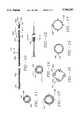
- FIG. 1is a side-elevational view of a sheath with an expandable distal extremity incorporating the present invention.
- FIG. 2is an enlarged cross-sectional view taken along the line 2--2 of FIG. 1.
- FIG. 2Ais an enlarged cross-sectional view similar to FIG. 2 but showing another embodiment of the sheath as shown in FIG. 1.
- FIG. 3is a large cross-sectional view of the distal extremity of the sheath shown in FIG. 1.
- FIG. 4is a cross-sectional view taken along the line 4--4 of FIG. 3.
- FIG. 4Ais a large cross-sectional view similar to FIG. 4 but showing another embodiment of the sheath of the present invention.
- FIG. 5is a side-elevational view of a balloon catheter for use with the sheath with expandable distal extremity shown in FIG. 1.
- FIG. 5Ais an enlarged sectional view of the distal extremity of the balloon catheter shown in FIG. 5.
- FIG. 6is an enlarged side-elevational view of the proximal and distal extremities of the combination of the sheath incorporating the present invention with a balloon catheter of the type shown in FIG. 5 utilized in enlarging the passageway through a stenosis in a vessel of a patient.
- FIG. 6Ais an enlarged cross-sectional view of the distal extremities of the assembly shown in FIG. 6 but showing a larger size balloon catheter creating a larger passageway through the stenosis after a rapid exchange of balloon catheters.
- FIG. 7Ais a side-elevational view of the distal extremity of a sheath incorporating the present invention being utilized for delivering a stent into the stenosis in a vessel of a patient.
- FIG. 7Bis a side-elevational view similar to that shown in FIG. 7A but showing the sheath with an expanded distal extremity to expand the stent to the stenosis.
- FIG. 7Cis a side-elevational view similar to FIGS. 7A and 7B but showing the distal extremity of the sheath returned to its unexpanded shape and leaving the stent in place.
- FIG. 8Ais a partial side-elevational view showing the sheath of the present invention being utilized for delivering a self-expanding stent into a stenosis and in which the self-expanding stent is covered by a sheath.
- FIG. 8Bis a side-elevational view showing the assembly in FIG. 8A with the sheath being partially retracted and with the self-expanding stent having its distal extremity expanded.
- FIG. 8Cis a side-elevational view similar to FIG. 8B but showing the sheath completely retracted from the self-expanding stent and the self-expanding stent expanded to engage the stenosis in the vessel to retain the passageway through the stenosis.
- FIG. 8Dis a side-elevational view similar to that shown in FIG. 8C but showing the use of a balloon catheter in the sheath to expand the self-expanding stent to enlarge the passageway through the stenosis.
- FIG. 9Ais a side-elevational view similar to that shown in FIG. 8 but showing a splittable sleeve as an alternative to the sleeve shown in FIG. 8A.
- FIG. 9Bis a view similar to that shown in FIG. 9A but showing the splittable sleeve being split apart to remove the same from the sheath.
- FIG. 10is another embodiment of a sheath incorporating the present invention with cutting blades provided on the expandable distal extremity.
- FIG. 11is a cross-sectional view taken along the line 11--11 of FIG. 10.
- FIG. 12is an enlarged view of a portion of the sheath shown in FIG. 10 with the cutting blades in extended positions.
- FIG. 13is a cross-sectional view taken along the line 13--13 of FIG. 12.
- FIG. 14is a cross-sectional view of another embodiment of a sheath of the present invention shown in FIG. 10 but with the cutting blades in recessed positions.
- FIG. 15is a cross-sectional view similar to FIG. 14 but showing the cutting blades extended.
- FIG. 16is a cross-sectional view of another embodiment of a sheath incorporating the present invention in which the distal expandable portion is formed of a non-elastomeric material.
- FIG. 17is a view similar to that shown in FIG. 16 but showing the cutting blades in extended positions.
- the sheath of the present inventionis for advancement into a vessel of a human being having a stenosis therein comprising a flexible elongate tubular member having proximal and distal extremities and having a lumen extending therethrough.
- a portion of the distal extremity of the flexible elongate tubular memberis formed so that its distal extremity is expandable so that it can be utilized for enlarging the passageway in a stenosis after the distal extremity of the sheath has been advanced into the stenosis.
- the sheathis provided with a construction that makes it pushable into the stenosis.
- the sheath 21 with an expandable distal extremityconsists of a flexible elongate tubular member 22 having proximal and distal extremities 23 and 24 and with a centrally disposed lumen 26 extending from the proximal extremity to the distal extremity.
- the flexible elongate member 22can be of a suitable size, as for example ranging from 0.018" to 0.060" and preferably a size of 3.5 French having an outside diameter of 0.045".
- the size of the sheathcan range from 2 to 6 French, whereas in other vessels in the body the sheath can range in sizes as great as 10 French.
- the flexible elongate member 22can have a suitable length as for example to provide a working length of from 130-160 centimeters and preferably 145 centimeters for the sheath 21.
- the flexible elongate tubular member 22can have a shaft portion 27 extending from the proximal extremity 23 for a suitable distance, as for example 100 to 110 centimeters and preferably approximately 104 centimeters, and having a lumen size of 0.030" with an outside diameter of 0.045" to provide a wall thickness of 0.006".
- the shaft portion 27can be formed of a suitable plastic such as a polyimide.
- a cylindrical braid 28can be incorporated therein as shown in the alternative construction in FIG. 2A. If desired, the braid 28 can extend the entire length of the shaft portion 27.
- the braidcan be formed of a suitable material such as stainless steel in the form of a wire or ribbon having a diameter and a thickness and width ranging from 0.001" to 0.0015".
- a suitable materialsuch as stainless steel in the form of a wire or ribbon having a diameter and a thickness and width ranging from 0.001" to 0.0015".
- such a braidcould have a pitch ranging from 80 to 110 and be comprised of 16 braid wires having a diameter of 0.0015" and formed of 304 stainless steel.
- the distal extremity of the shaft portion 27is provided with a plurality of perfusion openings or holes 31 which extend through the sidewall of the shaft portion 27 and which are in communication with the lumen 26.
- the perfusion holescan be of a suitable size, as for example 0.0135" in diameter. They can be six in number distributed circumferentially along a length of 0.100".
- the flexible elongate tubular member 22also includes an expandable portion 36 which adjoins radiopaque markers 37 and 38 provided on opposite ends of the expandable portion 36.
- the radiopaque markers 37 and 38are in the form of bands formed of radiopaque material so that the position of the expandable portion 36 can be readily ascertained during placement of the sheaths 21 as hereinafter described.
- the bands 37 and 38can be formed by radiopaque particles of a suitable material such as radiopaque salts of barium or bismuth which can be embedded or impregnated in the distal extremity of the shaft portion 27 as shown in FIG. 3 and in the proximal extremity of a conical portion 41 forming a part of the flexible elongate tubular member 22.
- the markers 37 and 38can be provided in the form of bands formed of a suitable material such as platinum or gold having a wall thickness of 0.003" and a width of 0.001".
- a suitable materialsuch as platinum or gold having a wall thickness of 0.003" and a width of 0.001".
- One of such bandscan be provided on opposite ends of the expandable portion 36 in the same positions as the markers 37 and 38 are provided.
- the expandable portion 36can have a suitable length, as for example 2 to 10 centimeters, and can be formed of a suitable expandable material, such as a non-elastomeric material, so that it cannot be expanded beyond a predetermined size. Alternatively it can be formed of an elastomeric material which is not so limited in its size of expansion. In the embodiment of the invention shown in FIGS. 1 through 4, it has been found to be desirable to use an elastomeric material for the expandable portion 36.
- the expandable portion 36In an unexpanded condition, can have an outside diameter substantially the same as the outside diameter of the shaft portion 27 and thus can have a diameter of 0.045" with a lumen 26 extending therethrough having a diameter of 0.030".
- the end portion 41can be formed of the same material as the shaft portion 27 and is also provided with a plurality of perfusion holes 42 of the same type as perfusion holes 31 and having the same size and spacing.
- the flexible elongate tubular member 22also includes a conical tip 46 formed of a suitable material such as a soft polyurethane that has a conical outer surface 47 and an opening 48 extending therethrough in communication with the lumen 26.
- the opening 48can be of a smaller diameter than the lumen 26, as for example it can have an inside diameter of 0.022", since it is only necessary that it be large enough so that a conventional guide wire 51 can extend therethrough.
- the conventional guide wirecan be of a suitable size as for example 0.010" to 0.18" or larger if desired.
- the guide wire 51can be of a conventional construction and therefore will not be described in detail.
- the shaft portion 27, the expandable portion 36, the end portion 41 and the conical tip 46 of the sheathcan be bonded together into a single unitary flexible elongate tubular member 22 in a suitable manner such as by an adhesive or by bonding of the same under heat.
- the expandable portion 36is formed of an elastomeric material
- a plurality of circumferentially spaced-apart substantially parallel elongate stiffening elements 56 formed of a suitable material such as plastic or stainless steelare embedded in the elastomeric material and extend longitudinally of the expandable portion 36.
- These elongate elements 56can be of suitable size, as for example 0.003" in diameter and have a length which extends substantially the entire length of the expandable portion 36.
- a cylindrical braid 58can be incorporated into the elastomeric material forming the expandable portion 36.
- a braidin order to have the desired amount of flexibility, should have a high pitch as for example a 30 to 60 pitch count, for example a 16-wire braid of the type hereinbefore described.
- the flexible elongate tubular member 22 forming the sheath 21be lubricous so that it can be readily introduced into a vessel with a minimum friction.
- a lubricous coating 61formed of a suitable material such as Teflon.
- the flexible elongate tubular member 22 shown thereinhas a proximal extremity which can be made to be free of attachments.
- a proximal extremitywhich can be made to be free of attachments.
- Such removable attachments as shown in FIG. 1take the form of a Touhy-Borst adapter 66.
- Such a Touhy-Borst adapter 66is well known to those skilled in the art and are adapted to be removably secured to the proximal extremity 23 of the flexible elongate tubular member 22 and include a seal 67 which can be compressed into sealing engagement with the proximal extremity 23 to form a high pressure seal therewith by rotation of the cap 68.
- a hemostasis valve assembly 71is removably secured to the Touhy-Borst adapter 66.
- the valve assembly 71is of a conventional type and includes a resilient seal 72 which by compression by rotation of the threaded cap 73 can form a liquid-tight seal with respect to the guide wire 51 extending therethrough.
- a side port 76 in communication with the lumen 26is provided in the assembly 71.
- the port 76is connected by flexible tubing 77 formed of a suitable material such as clear plastic connected to a stop cock assembly 78 provided with a tab-like handle 78 adapted to be engaged by the fingers of the hand for moving the stop cock assembly between open and closed positions.
- the stop cock assembly 78is provided with a Luer-type fitting 81 which can be connected to another Luer-type fitting for supplying a liquid such as a saline solution to the lumen 26 of the sheath 21.
- the sheath 21can be utilized with conventional angioplasty balloon catheters.
- balloon catheterstypically are for use with an over-the-wire catheter or are provided with a fixed guide wire
- a simplified less expensive balloon cathetercan be utilized such as the balloon catheter 91 shown in FIG. 5.
- the balloon catheter 91consists of a flexible elongate tubular member 92 having a suitable length, as for example 170 centimeters, and having a diameter of 0.018" to 0.025". It is formed of a suitable plastic such as a polyimide and has proximal and distal extremities 23 and 24 with a flow passage or lumen 96 extending from the proximal extremity to the distal extremity.
- the lumen 96can be of a suitable size, as for example 0.010" to 0.012", to provide a sufficiently large lumen so that inflation and deflation of a balloon 97 mounted on the distal extremity thereof can be accomplished in a suitable time period, as for example from 5 to 10 seconds.
- the balloon 97typically is a balloon formed of a non-elastomeric material which has a suitable inflated diameter ranging from 1.5 to 5.0 millimeters and preferably approximately 2.0 to 4.0 millimeters.
- the flexible elongate tubular member 92 with its balloon 97can be formed from a single piece of plastic such as polyethylene, Nylon or other notable balloon material.
- the balloon 97can be formed in a manner well known to those skilled in the art by inflating the portion of the tubular member 92 which is to be formed into the balloon of the desired size into a mold under heat. It may thereafter be cooled and deflated to collapse into the configuration shown in FIG. 5.
- the interior of the balloon 97is in communication with the lumen 96.
- the balloon 97can be formed of a different material and then secured to the distal extremity 94 of the flexible elongate tubular member 92 by suitable means such as an adhesive.
- the distal extremity of the balloon 97is sealed so that the balloon can be inflated with a fluid introduced through the lumen 96.
- a Luer-type fitting in the form of a removable Touhy-Borst adapter 98is mounted on the proximal extremity 93 of the flexible elongate tubular member 92 and is adapted to have secured thereto an inflation device 101 of a conventional type which can be utilized for inflating the balloon 97.
- the balloon catheter 91 to be utilized with the sheath 21should have a balloon 97 with a length slightly less than the length of the expandable portion 36.
- a flexible elongate element 102formed of a suitable material such as stainless steel having a diameter ranging from 0.003" to 0.006" can be provided having helical coils 103 and 104 on opposite ends.
- Coil 103is frictionally secured in the lumen 96 in the flexible elongate tubular member 92 just proximal of the proximal extremity of balloon and permits passage of the inflation medium for the balloon 97 from the lumen 96 into the interior of the balloon 97.
- the other coil 104is secured in the distal extremity of the balloon 97 in a suitable fluid-tight seal provided by an adhesive (not shown).
- a radiopaque marker 105is mounted on the element 102 equi-distant the ends of the same.
- a braid(not shown) can be embedded in the balloon 97 to impart improved torquability as well as pushability for the balloon catheter.
- a guide wire 51 of a conventional typecan be advanced into the guiding catheter until its distal extremity has traversed the stenosis which it is desired to treat, as for example a stenosis 106 which is at least partially occluding the vessel 107.
- the sheath 21can be taken and the proximal extremity of the guide wire 51 inserted into the opening 48 and thereafter threaded onto the guide wire and advanced into the guiding catheter over the guide wire so that the guide wire extends through the lumen 26. Because of lubricous qualities of the coating 61, the sheath 21 can be readily advanced over the guide wire until the expandable portion 36 is disposed within the stenosis 106 as for example to the position as shown in FIG. 6. The advancement of the sheath 21 can be observed by the movement of the radiopaque markers 37 and 38.
- the sheath 21can have the guide wire 51 threaded into the same and the guide wire and the sheath advanced simultaneously or step by step into the guiding catheter until the guide wire first traverses the stenosis and thereafter is followed by the expandable portion 36 of the sheath 21.
- bloodcan continue to perfuse through the stenosis by passing in through the holes 31 through the lumen 26 and then out the holes 42 on the other side of the stenosis.
- the guide wire 51can be removed.
- the Touhy-Borst adapter 66can be mounted on the proximal extremity.
- a high pressure sealis formed with respect to the proximal extremity by compressing the seal 67 by rotation of the cap 68.
- the hemostasis valve assembly 71can be attached to the Touhy-Borst adapter 66.
- a saline solutioncan be supplied to the lumen 26 of the sheath by connecting a suitable source applied to the fitting 81 and opening the stop cock 79 to permit a saline solution to be introduced through the tubing 77 and into the hemostasis valve assembly 71 into the lumen and out the perfusion openings 31 and 42 from opposite sides of the stenosis 106 and out the opening 48.
- one of the balloon catheters 91can be introduced directly into the lumen 26 or thereafter by opening the hemostasis valve assembly 71 and by introducing the distal extremity of the balloon catheter 91 through the hemostasis valve assembly and advancing it in the lumen 26 until it has been advanced into the expandable portion 36 of the sheath 21 and so that it is also disposed of in the stenosis 106.
- Pushability of the balloon 97is enhanced by the presence of the flexible elongate element 102 in the balloon 97 to provide column strength. With the balloon 97 in a deflated condition, blood will continue to perfuse past the balloon 97 into the openings 31 and out through the openings or holes 42.
- the inflation device 101can be attached to the fitting 98 and the balloon 97 inflated for example by placing a radiopaque contrast liquid into the interior of the balloon through the lumen 96 to cause the balloon 97 formed of a non-elastomeric material to expand and to thereby expand the expandable portion 36 of the sheath 21 to compress the plaque 106 and to form a larger flow passage 108 through the stenosis formed by the plaque 106.
- the expandable portion 36can be expandable one or more times by successfully inflating and deflating the balloon 97 by use of the inflation device 101.
- the inflation and deflation times for the balloon 97are relatively short as for example within 5 to 10 seconds because of the relatively large size of the lumen 96 for inflating the balloon 97.
- bloodcan continue to perfuse through the sheath 21 in the manner hereinbefore described. Thereafter, the balloon catheter 91 can be removed.
- the balloon catheter 91 in placecan be readily deflated and removed followed by insertion of another balloon catheter 91 followed by inflation and deflation of the balloon 97 of the additional balloon catheter to increase the passage 108 through the stenosis 106 to the desired size.
- the sheath 21serves as a rapid exchange sheath permitting the rapid exchange of different size balloon catheters.
- the distal extremity of the sheath 21remains in the stenosis so that the larger size balloon catheters can be readily introduced into the expandable portion 36 of the sheath 21.
- a rapid exchange sheathBy use of such a rapid exchange sheath, it can be seen that the necessity for using a rapid exchange balloon catheter is eliminated. Also it can be seen that with the use of the sheath with an expandable distal extremity, it is possible to utilize relatively inexpensive balloon catheters to reduce the cost of an angioplasty procedure.
- the balloon 97can be deflated and thereafter, the balloon catheter 91 can be removed separately or removed as a unit with the sheath 21, after which the femoral artery can be closed in a conventional manner.
- FIGS. 7A, 7B and 7Cthere are shown illustrations showing how the sheath 21 of the present invention can be utilized for delivering an expandable stent 116 of a conventional type into a stenosis 106.
- the stent 116can be placed over the expandable portion 36 of the sheath 21 and frictionally retained thereon and advanced over a guide wire 51 which has traversed the stenosis in the manner hereinbefore described so that the expandable portion 36 with the stent 116 carried thereby is disposed in the stenosis.
- FIG. 7A, 7B and 7Cthere are shown illustrations showing how the sheath 21 of the present invention can be utilized for delivering an expandable stent 116 of a conventional type into a stenosis 106.
- a balloon catheter 91 of the type hereinbefore describedcan be advanced into the sheath 21 so that its balloon 97 is disposed within the expandable portion 36 to cause expansion of the stent 116 and also at the same time to cause compression of the plaque forming the stenosis 106 as shown in FIG. 7B.
- bloodcan perfuse through the stenosis by passing into the holes 31 and out the holes 42.
- the balloon catheter 91can be deflated causing the expandable portion 36 to collapse as shown in FIG.
- FIGS. 8A through 8Dillustrate the manner in which the sheath 21 with the expandable distal extremity can be utilized for placement of a self-expanding stent 121.
- the self-expanding stent 121can be of a type well known to those skilled in the art and is friction retained on the expandable portion 36 as shown in FIG. 8A.
- a sleeve 126 of a suitable lubricous plastic material such as Teflonhaving a wall thickness of 0.002" to 0.015" and having proximal and distal extremities 27 and 28 with the distal extremity being disposed over and enclosing the self-expanding stent 121 to prevent expansion of the same.
- the proximal extremityis provided with the fitting 129 of a suitable type so that the sleeve 126 can be grasped by the hand to facilitate removal of the same.
- the sheath 21 with the self-expanding stent mounted on the expandable portion 36 and held in place by the sleeve 126can be advanced over the guide wire 51 into the stenosis 106.
- the guide wire 61can then be removed.
- the Touhy-Borst adapter 66can be removed from the proximal extremity 23 of the flexible elongate tubular member 22 so that the sleeve 126 can be retracted permitting the distal extremity of the self-expanding stent 121 to begin expanding as shown in FIG. 8B.
- the sleeve 126can be completely removed so that it clears the self-expanding stent 121 permitting the self-expanding stent 121 to frictionally engage the stenosis 106 and to be retained therein.
- a balloon catheter 91 of the type hereinbefore describedis advanced through the hemostasis valve assembly 71 (not shown) through the Touhy-Borst adapter 66 and into the lumen 26 of the sheath 21 until the balloon 97 of the balloon catheter 91 is disposed in the expandable portion 36 of the sheath 21.
- the balloon 97can be inflated in the manner hereinbefore described to cause expansion of the expandable portion 36 to cause the self-expanding stent 121 to expand still further and to form a larger passageway through the stenosis 106.
- the balloon 97can be deflated and the balloon catheter 91 removed. The expandable portion 36 collapses permitting the sheath 21 to be removed.
- a splittable sleeve 131which can be mounted on the sheath 21 and has distal extremity (not shown) extend over the self-expanding stent 121.
- the splittable sleeve 131can be readily removed by grasping the separate finger handles 132 and 133 provided on the proximal extremity of the same and pulling them apart by the fingers of the hand to cause the sleeve 131 to split on opposite sides longitudinally of the sleeve so that the sleeve 131 can be pulled proximally and progressively split apart so that its distal extremity clears the self-expanding stent 121 to permit it to expand into and frictionally engage the stenosis 106.
- the entire splittable sleevecan be split apart and removed without removal of the Touhy-Borst adapter 66 or any other attachments which may be present on the proximal extremity of the sheath 121.
- the self-expanding sheath 121can be further expanded in the manner hereinbefore described after which the sheath 21 can be removed.
- sheath 151is shown in FIG. 10 and consists of a flexible elongate tubular member 152 formed of a suitable plastic hereinbefore described which is provided with proximal and distal extremities 153 and 154 and a lumen 156 extending from the proximal extremity 153 to the distal extremity 154. It is constructed in a manner very similar to the embodiments hereinbefore described.
- shaft portions 152a and 152bwith the shaft portion 152a being approximately 104 centimeters long and being formed of a braided polyimide with 80-110 pitch count and portion 152b being approximately 30 centimeters in length formed of a braided polyimide having 210-280 pitch count.
- portion 152chaving perfusion holes 158 therein open to the central lumen 156 permitting blood to perfuse through a portion 152d which is an expandable portion and another portion 152e having outlet holes 159 formed therein in communication with the lumen 156.
- a conical portion 152fwhich is relatively soft and pliable.
- radiopaque markers 161 and 162 of the type hereinbefore describedare disposed proximally and distally of the inflatable portion 152d.
- the braidsare utilized to provide the desired pushability and torquability for the sheath 151.
- the expandable portion 152Dis also provided with a braid to give the desired pushability to the sheath.
- the sheath 151 shown in FIGS. 10 and 11there is provided means for cutting the plaque 106 so as to break it apart in the event it calcified so it is relatively hard and cannot be readily compressed or expanded by the mere force of the balloon catheter 91 hereinbefore described.
- a plurality of cutting blades 156have been provided which are mounted in the material forming the expandable portion 152d.
- the blades 166can be formed of a suitable material such as stainless steel having a length of approximately 2 centimeters and having a blade thickness of 0.005" and a height of 0.01".
- the bladesare provided with cutting edges 167 which are triangular in cross section as shown in FIG. 11.
- Each of the blades 166is provided with a foot portion 166a which is seated in the material as for example the elastomeric material forming the expandable portion 152d. As shown in FIG. 11 before expansion of the expandable portion 152d, the cutting edges 167 of the blade 166 are disposed just below the circumferential surface 168 of the expandable portion 152d.
- the sheath 151can be advanced over a guide wire 51 in the same manner in which the sheath 21 was advanced into the stenosis 106.
- a balloon catheter 91 of the type hereinbefore describedcan be advanced into the sheath 151 so that its balloon 97 is in registration with the stenosis 106.
- Expansion of the balloon 97causes the cutting edges 167 of the cutting blades 166 to pierce the outer circumferential surface 168 of the expandable portion 152d to extend radially therefrom and to cut longitudinally extending slits into the plaque forming the stenosis 106.
- the balloon 97can be deflated and the distal extremity of the sheath 151 rotated after which the balloon 97 again can be inflated to cause additional cuts or slits to be made in the plaque forming the stenosis 106.
- the balloon 97can be deflated after which the expandable portion 152 will collapse bringing inwardly the blades 166 so that they no longer penetrate through the circumferential surface 168 after which the sheath 151 can be removed.
- a sleeve(not shown) of a suitable flexible material may be advanced over the sheath 151 until it covers the blades 166 after which the sheath 151 along with the cover can be removed.
- FIGS. 14 and 15Another embodiment of a sheath having recessed cutting blades is shown in FIGS. 14 and 15 which correspond to FIGS. 11 and 13.
- a sheath 171 having an expandable sheath portion 171awhich is formed of an elastomeric material that is provided with longitudinally extending arcuate recesses 176 extending longitudinally thereof which have mounted therein the blades 166 mounted in those recesses with the cutting edges 167 being recessed below the peripheral surface of the portion 171a as shown in FIG. 14.
- the cutting edges 167are advanced so that they extend around the peripheral surface of the portion 171a and cut slits into the plaque forming the stenosis 106. Additional slits can be made in the manner hereinbefore described with the embodiment shown in FIGS. 11, 12 and 13.
- the ballooncan be deflated after which the portion 171a will collapse permitting the sharp cutting edges 167 to be retracted so that they cannot cut the vessel wall when the sheath 171 is retracted from the vessel.
- the sheath 171can be provided with a sleeve (not shown) covering the cutting edges 167 prior to the time that the sheath 171 is removed.
- FIGS. 16 and 17Another embodiment of the sheath incorporating the present invention shown in FIGS. 16 and 17 in which a sheath 181 is provided with an inflatable distal extremity provided by a non-elastic expandable portion 181a in which longitudinally extending portions 181b are folded in a clockwise direction and carry within the folds cutting blades 186 of the type hereinbefore described. These blades 186 are protected by the folds 181b of the expandable portion 181a.
- the folds 181bunfold to form a circle in cross section and to move the cutting blades 186 carried thereby outwardly in a radial direction to cause slits to be formed in the plaque of the stenosis 106 in the manner hereinbefore described. Additional slits also can be formed also in the manner hereinbefore described.
- the balloon 97 of the balloon catheter 91can be deflated and removed. Deflation of the balloon will cause collapse of the expandable portion 181a causing the folds 181b to be made to cover the blades 186.
- a sheath with an expandable distal extremitywhich has many advantages particularly when performing medical procedures such as angioplasty procedures.
- the sheathhas sufficient stiffness and/or column strength so that it can be advanced on its own over a guide wire into a stenosis. It is provided with holes therein communicating with the lumen within the sheath thereby permitting perfusion of blood across the stenosis when the expandable portion of the sheath is in position and the stenosis.
- the sheathbecause of its construction makes it possible the rapid exchange of various sizes of balloon catheters without losing the desired position within the stenosis within the vessel of the patient this makes it possible to utilize several balloons of different sizes to enlarge the flow passage through the stenosis.
- a stentcan be carried by the inflatable portion of the piece and then expanded into position within the stenosis after which the sheath can be removed. Expandable and self-expanding sheaths can be utilized.
- the expandable portion of the sheathcan be provided with longitudinally extending cutting blades which can be yieldably urged into engagement with the plaque forming the stenosis to form slits in the stenosis to more readily facilitate expansion of the flow passage through the stenosis.
- the sheathin addition to having the desired pushability also has the necessary torquability to make it possible to advance the sheath through tortuous vessels over the guide wire.
- the sheathis lubricous so that it can be readily advanced through the vessel with a minimum of resistance and trauma to the vessel through which it is being introduced.
- the attachments or accessories provided for the proximal extremity of the sheathare removable so that removable sleeves can be provided on the exterior of the sheath when necessary.
- the hemostasis valveprevents blood from leaking out during the procedure.
- the sheathis constructed in such a manner so that it can be constructed inexpensively. It can be formed utilizing a single part construction or a multi-part construction as hereinbefore described. The use of the sheath with the balloon catheters greatly reduces the cost of angioplasty procedure.
- sheath and the method of using the samemay have been described principally in connection with angioplasty procedures, it is readily apparent that the sheath and the balloon catheters for use therewith can be utilized in other vessels in the body as for example arteries and veins.
Landscapes
- Health & Medical Sciences (AREA)
- Engineering & Computer Science (AREA)
- Biomedical Technology (AREA)
- Cardiology (AREA)
- Oral & Maxillofacial Surgery (AREA)
- Transplantation (AREA)
- Heart & Thoracic Surgery (AREA)
- Vascular Medicine (AREA)
- Life Sciences & Earth Sciences (AREA)
- Animal Behavior & Ethology (AREA)
- General Health & Medical Sciences (AREA)
- Public Health (AREA)
- Veterinary Medicine (AREA)
- Media Introduction/Drainage Providing Device (AREA)
Abstract
Description
Claims (23)
Priority Applications (1)
| Application Number | Priority Date | Filing Date | Title |
|---|---|---|---|
| US08/728,769US5766203A (en) | 1995-07-20 | 1996-10-10 | Sheath with expandable distal extremity and balloon catheters and stents for use therewith and method |
Applications Claiming Priority (2)
| Application Number | Priority Date | Filing Date | Title |
|---|---|---|---|
| US50492995A | 1995-07-20 | 1995-07-20 | |
| US08/728,769US5766203A (en) | 1995-07-20 | 1996-10-10 | Sheath with expandable distal extremity and balloon catheters and stents for use therewith and method |
Related Parent Applications (1)
| Application Number | Title | Priority Date | Filing Date |
|---|---|---|---|
| US50492995AContinuation | 1995-07-20 | 1995-07-20 |
Publications (1)
| Publication Number | Publication Date |
|---|---|
| US5766203Atrue US5766203A (en) | 1998-06-16 |
Family
ID=24008300
Family Applications (1)
| Application Number | Title | Priority Date | Filing Date |
|---|---|---|---|
| US08/728,769Expired - Fee RelatedUS5766203A (en) | 1995-07-20 | 1996-10-10 | Sheath with expandable distal extremity and balloon catheters and stents for use therewith and method |
Country Status (1)
| Country | Link |
|---|---|
| US (1) | US5766203A (en) |
Cited By (194)
| Publication number | Priority date | Publication date | Assignee | Title |
|---|---|---|---|---|
| US5893868A (en)* | 1997-03-05 | 1999-04-13 | Scimed Life Systems, Inc. | Catheter with removable balloon protector and stent delivery system with removable stent protector |
| WO1999039649A1 (en)* | 1998-02-10 | 1999-08-12 | Dubrul William R | Occlusion, anchoring, tensioning and flow direction apparatus and methods for use |
| US5992000A (en)* | 1997-10-16 | 1999-11-30 | Scimed Life Systems, Inc. | Stent crimper |
| US6059823A (en)* | 1996-02-13 | 2000-05-09 | Scimed Life Systems, Inc. | Endovascular apparatus |
| US6077273A (en)* | 1996-08-23 | 2000-06-20 | Scimed Life Systems, Inc. | Catheter support for stent delivery |
| US6096052A (en)* | 1998-07-08 | 2000-08-01 | Ovion, Inc. | Occluding device and method of use |
| US6123720A (en)* | 1996-08-19 | 2000-09-26 | Scimed Life Systems, Inc. | Stent delivery system with storage sleeve |
| US6129700A (en)* | 1998-12-04 | 2000-10-10 | Advanced Cardiovascular Systems, Inc. | Contrast medium injection device and method of use |
| US6152944A (en)* | 1997-03-05 | 2000-11-28 | Scimed Life Systems, Inc. | Catheter with removable balloon protector and stent delivery system with removable stent protector |
| US6168616B1 (en) | 1997-06-02 | 2001-01-02 | Global Vascular Concepts | Manually expandable stent |
| US6231588B1 (en) | 1998-08-04 | 2001-05-15 | Percusurge, Inc. | Low profile catheter for angioplasty and occlusion |
| US6254609B1 (en)* | 1999-01-11 | 2001-07-03 | Scimed Life Systems, Inc. | Self-expanding stent delivery system with two sheaths |
| US6258098B1 (en) | 1998-05-08 | 2001-07-10 | William N. Taylor | Stent placement and removal system |
| US6260890B1 (en)* | 1999-08-12 | 2001-07-17 | Breg, Inc. | Tubing connector |
| US6287314B1 (en)* | 1998-04-21 | 2001-09-11 | Advanced Cardiovascular Systems, Inc. | Stent deploying catheter system |
| US6306106B1 (en) | 2000-06-19 | 2001-10-23 | Advanced Cardiovascular Systems, Inc. | Diagnostic sheath for reduced embolic risk |
| US6312407B1 (en) | 1995-06-05 | 2001-11-06 | Medtronic Percusurge, Inc. | Occlusion of a vessel |
| US6330884B1 (en)* | 1997-11-14 | 2001-12-18 | Transvascular, Inc. | Deformable scaffolding multicellular stent |
| US6336934B1 (en) | 1997-11-07 | 2002-01-08 | Salviac Limited | Embolic protection device |
| EP1169970A1 (en)* | 2000-07-04 | 2002-01-09 | Transgene S.A. | Device for the administration of a composition in a conduit of a human or animal body |
| US6338709B1 (en) | 1998-02-19 | 2002-01-15 | Medtronic Percusurge, Inc. | Intravascular radiation therapy device and method of use |
| US6352547B1 (en) | 1999-09-22 | 2002-03-05 | Scimed Life Systems, Inc. | Stent crimping system |
| US6358244B1 (en) | 1996-07-12 | 2002-03-19 | Endo Surgical Devices, Inc. | Endarterectomy surgical instrument and procedure |
| US6360577B2 (en) | 1999-09-22 | 2002-03-26 | Scimed Life Systems, Inc. | Apparatus for contracting, or crimping stents |
| US6375660B1 (en)* | 1999-11-22 | 2002-04-23 | Cordis Corporation | Stent delivery system with a fixed guide wire |
| US20020049467A1 (en)* | 1997-11-07 | 2002-04-25 | Paul Gilson | Embolic protection system |
| US20020052638A1 (en)* | 1996-05-20 | 2002-05-02 | Gholam-Reza Zadno-Azizi | Method and apparatus for emboli containment |
| US6387117B1 (en) | 1999-09-22 | 2002-05-14 | Scimed Life Systems, Inc. | Stent crimping system |
| US6432116B1 (en) | 1996-12-18 | 2002-08-13 | Ovion, Inc. | Occluding device and method of use |
| US6447540B1 (en)* | 1996-11-15 | 2002-09-10 | Cook Incorporated | Stent deployment device including splittable sleeve containing the stent |
| US20020163104A1 (en)* | 2001-03-26 | 2002-11-07 | Tom Motsenbocker | Balloon folding technology |
| US20030004537A1 (en)* | 2001-06-29 | 2003-01-02 | Boyle William J. | Delivery and recovery sheaths for medical devices |
| US6506194B1 (en)* | 2000-06-08 | 2003-01-14 | Mohammed Ali Hajianpour | Medullary plug including an external shield and an internal valve |
| US6517569B2 (en)* | 1998-09-14 | 2003-02-11 | Endocare, Inc. | Insertion device for stents and methods for use |
| US6544247B1 (en)* | 1998-07-16 | 2003-04-08 | Medtronic, Inc. | Introducer system |
| US6565591B2 (en) | 2000-06-23 | 2003-05-20 | Salviac Limited | Medical device |
| US6629350B2 (en) | 2000-06-08 | 2003-10-07 | Tom Motsenbocker | Stent crimping apparatus and method |
| US6645222B1 (en)* | 1998-05-13 | 2003-11-11 | Arteria Medical Science, Inc. | Puncture resistant branch artery occlusion device and methods of use |
| US6652569B1 (en) | 1998-05-08 | 2003-11-25 | Biu Biomedical Innovations (Urology) Inc. | Stent placement and removal |
| WO2003101347A1 (en) | 2002-05-31 | 2003-12-11 | Wilson-Cook Medical Inc. | Stent introducer apparatus |
| US6679902B1 (en)* | 2000-07-19 | 2004-01-20 | Advanced Cardiovascular Systems, Inc. | Reduced profile delivery sheath for use in interventional procedures |
| US6726701B2 (en) | 1999-05-07 | 2004-04-27 | Salviac Limited | Embolic protection device |
| US6730105B2 (en) | 1988-07-29 | 2004-05-04 | Samuel Shiber | Clover leaf shaped tubular medical device |
| US6752819B1 (en) | 1998-04-02 | 2004-06-22 | Salviac Limited | Delivery catheter |
| US20040127920A1 (en)* | 2001-08-23 | 2004-07-01 | Radisch Herbert R | Apparatus for supporting a segmented blade on a balloon catheter |
| US6769161B2 (en)* | 1997-10-16 | 2004-08-03 | Scimed Life Systems, Inc. | Radial stent crimper |
| US20040215223A1 (en)* | 2003-04-25 | 2004-10-28 | Shaw William J. | Cutting stent and balloon |
| US20040260332A1 (en)* | 1997-11-12 | 2004-12-23 | Genesis Technologies Llc | Body passageway occluder and method |
| US20040255447A1 (en)* | 2001-07-26 | 2004-12-23 | Kendall Mark Anthony Fernance | Particle cassette, method and kit therefor |
| US20040260333A1 (en)* | 1997-11-12 | 2004-12-23 | Dubrul William R. | Medical device and method |
| US20040267196A1 (en)* | 2002-02-27 | 2004-12-30 | Shogo Miki | Balloon catheter for tentative vaso-occlusion |
| US6855153B2 (en) | 2001-05-01 | 2005-02-15 | Vahid Saadat | Embolic balloon |
| US20050085844A1 (en)* | 2002-12-24 | 2005-04-21 | Ovion, Inc. | Contraceptive device and delivery system |
| US20050102020A1 (en)* | 2000-07-24 | 2005-05-12 | Jeffrey Grayzel | Stiffened balloon catheter for dilatation and stenting |
| US20050124931A1 (en)* | 1998-04-27 | 2005-06-09 | Artemis Medical, Inc. | Particle-removing medical device and method |
| US20050125021A1 (en)* | 2003-12-05 | 2005-06-09 | Nance Edward J. | Expandable percutaneous sheath |
| US20050124937A1 (en)* | 2003-12-05 | 2005-06-09 | Kick George F. | Expandable percutaneous sheath |
| US20050131453A1 (en)* | 1998-03-13 | 2005-06-16 | Parodi Juan C. | Apparatus and methods for reducing embolization during treatment of carotid artery disease |
| US20050149082A1 (en)* | 2003-12-31 | 2005-07-07 | Carl Yee | Microsurgical balloon with protective reinforcement |
| US6918921B2 (en) | 1999-05-07 | 2005-07-19 | Salviac Limited | Support frame for an embolic protection device |
| US20050165430A1 (en)* | 2004-01-23 | 2005-07-28 | Hiroshi Kono | Atherectomy head and atherectomy catheter using the same |
| US20050171591A1 (en)* | 2004-01-29 | 2005-08-04 | Scimed Life Systems, Inc. | Catherter tip |
| US20050192616A1 (en)* | 2004-02-02 | 2005-09-01 | Callister Jeffrey P. | Contraceptive with permeable and impermeable components |
| US20050209633A1 (en)* | 2004-02-02 | 2005-09-22 | Ovion, Inc. | Enhancing tissue ingrowth for contraception |
| US20050217680A1 (en)* | 1996-12-18 | 2005-10-06 | Callister Jeffrey P | Occluding device and method of use |
| US6964672B2 (en) | 1999-05-07 | 2005-11-15 | Salviac Limited | Support frame for an embolic protection device |
| US20050288551A1 (en)* | 2004-04-28 | 2005-12-29 | Ams Research Corporation | Endoscopic delivery of medical devices |
| US6994689B1 (en) | 1995-06-05 | 2006-02-07 | Medtronic Vascular, Inc. | Occlusion of a vessel |
| US7011673B2 (en)* | 1999-11-22 | 2006-03-14 | Fischell Robert E | Stent delivery system with a fixed guide wire |
| US7014647B2 (en) | 1999-05-07 | 2006-03-21 | Salviac Limited | Support frame for an embolic protection device |
| US20060069423A1 (en)* | 1999-11-22 | 2006-03-30 | Fischell David R | Means and method for treating an intimal dissection after stent implantation |
| US7037320B2 (en) | 2001-12-21 | 2006-05-02 | Salviac Limited | Support frame for an embolic protection device |
| US20060111736A1 (en)* | 2004-11-23 | 2006-05-25 | Kelley Greg S | Serpentine cutting blade for cutting balloon |
| US20060135981A1 (en)* | 2004-09-09 | 2006-06-22 | Jay Lenker | Expandable transluminal sheath |
| US20060135980A1 (en)* | 2004-12-20 | 2006-06-22 | Scimed Life Systems, Inc. | Balloon with stepped sections and implements |
| US20060135962A1 (en)* | 2004-09-09 | 2006-06-22 | Kick George F | Expandable trans-septal sheath |
| US7066951B2 (en) | 2000-02-02 | 2006-06-27 | Trivascular, Inc. | Delivery system and method for expandable intracorporeal device |
| US7094218B2 (en) | 2004-03-18 | 2006-08-22 | C. R. Bard, Inc. | Valved catheter |
| US20060247674A1 (en)* | 2005-04-29 | 2006-11-02 | Roman Ricardo D | String cutting balloon |
| US20060265000A1 (en)* | 1996-05-20 | 2006-11-23 | Azizi Gholam-Reza Z | Exchange method for emboli containment |
| US20060271093A1 (en)* | 2005-05-27 | 2006-11-30 | Holman Thomas J | Fiber mesh controlled expansion balloon catheter |
| US7144408B2 (en) | 2002-03-05 | 2006-12-05 | Salviac Limited | Embolic protection system |
| US20060282116A1 (en)* | 2004-01-20 | 2006-12-14 | Scimed Life Systems, Inc. | Sheath for use with an embolic protection filtering protection |
| US20060293707A1 (en)* | 2002-10-01 | 2006-12-28 | Scimed Life Systems, Inc. | Embolic protection device with lesion length assessment markers |
| US20070066991A1 (en)* | 2005-09-16 | 2007-03-22 | Cook Incorporated | Embolic protection device |
| US20070083253A1 (en)* | 2005-10-06 | 2007-04-12 | Fischell David R | Stent delivery system using a steerable guide wire |
| US20070100373A1 (en)* | 2005-11-02 | 2007-05-03 | Cook Incorporated | Embolic protection device having reduced profile |
| US20070227544A1 (en)* | 2006-03-30 | 2007-10-04 | Betsy Swann | Methods and devices for deployment into a lumen |
| US20080183187A1 (en)* | 2007-01-30 | 2008-07-31 | Cardiac Pacemakers, Inc. | Direct delivery system for transvascular lead |
| US20080183264A1 (en)* | 2007-01-30 | 2008-07-31 | Cardiac Pacemakers, Inc. | Electrode configurations for transvascular nerve stimulation |
| US20080183253A1 (en)* | 2007-01-30 | 2008-07-31 | Cardiac Pacemakers, Inc. | Neurostimulating lead having a stent-like anchor |
| US20080183255A1 (en)* | 2007-01-30 | 2008-07-31 | Cardiac Pacemakers, Inc. | Side port lead delivery system |
| US20080183254A1 (en)* | 2007-01-30 | 2008-07-31 | Cardiac Pacemakers, Inc. | Dual spiral lead configurations |
| US7491215B2 (en) | 1999-05-07 | 2009-02-17 | Salviac Limited | Filter element for embolic protection device |
| US7491216B2 (en) | 1997-11-07 | 2009-02-17 | Salviac Limited | Filter element with retractable guidewire tip |
| US20090054924A1 (en)* | 2000-06-23 | 2009-02-26 | Salviac Limited | Medical device |
| US20090054922A1 (en)* | 2007-08-23 | 2009-02-26 | Broker Harshal S | Apparatus and Method for the Intravascular Control of Trauma |
| US20090076593A1 (en)* | 2007-09-14 | 2009-03-19 | Cook Incorporated | Expandable device for treatment of a stricture in a body vessel |
| US20090171284A1 (en)* | 2007-12-27 | 2009-07-02 | Cook Incorporated | Dilation system |
| US20090171382A1 (en)* | 2007-12-27 | 2009-07-02 | Wilson-Cook Medical Inc. | Delivery system and method of delivery for treating obesity |
| US20090171283A1 (en)* | 2007-12-27 | 2009-07-02 | Cook Incorporated | Method of bonding a dilation element to a surface of an angioplasty balloon |
| US20090182408A1 (en)* | 1995-03-24 | 2009-07-16 | Boston Scientific Scimed, Inc. | Selective Coating of a Balloon Catheter with Lubricious Material for Stent Deployment |
| US7578803B2 (en) | 2004-03-18 | 2009-08-25 | C. R. Bard, Inc. | Multifunction adaptor for an open-ended catheter |
| US20090287182A1 (en)* | 2008-05-14 | 2009-11-19 | Onset Medical Corporation | Expandable iliac sheath and method of use |
| US7637893B2 (en) | 2004-04-30 | 2009-12-29 | C. R. Bard, Inc. | Valved sheath introducer for venous cannulation |
| US20100010521A1 (en)* | 2008-07-10 | 2010-01-14 | Cook Incorporated | Cutting balloon with movable member |
| US7686020B2 (en) | 1995-06-07 | 2010-03-30 | Conceptus, Inc. | Contraceptive transcervical fallopian tube occlusion devices and methods |
| US7722568B2 (en) | 2007-01-29 | 2010-05-25 | Onset Medical Corporation | Expandable intra-aortic balloon pump sheath |
| US20100145267A1 (en)* | 2008-11-10 | 2010-06-10 | Onset Medical Corporation | Expandable spinal sheath and method of use |
| US20100204724A1 (en)* | 1998-05-13 | 2010-08-12 | Michael Hogendijk | Apparatus and methods for reducing embolization during treatment of carotid artery disease |
| US7854731B2 (en) | 2004-03-18 | 2010-12-21 | C. R. Bard, Inc. | Valved catheter |
| US7875019B2 (en) | 2005-06-20 | 2011-01-25 | C. R. Bard, Inc. | Connection system for multi-lumen catheter |
| US7883502B2 (en) | 2004-03-18 | 2011-02-08 | C. R. Bard, Inc. | Connector system for a proximally trimmable catheter |
| US7892469B2 (en) | 1998-04-21 | 2011-02-22 | Advanced Cardiovascular Systems, Inc. | Method of making a non-compliant balloon for a catheter |
| US7892203B2 (en) | 2004-09-09 | 2011-02-22 | Onset Medical Corporation | Expandable transluminal sheath |
| US20110144690A1 (en)* | 2008-05-14 | 2011-06-16 | Onset Medical Corporation | Expandable transapical sheath and method of use |
| US7976557B2 (en) | 2004-06-23 | 2011-07-12 | Boston Scientific Scimed, Inc. | Cutting balloon and process |
| US8034100B2 (en) | 1999-03-11 | 2011-10-11 | Endologix, Inc. | Graft deployment system |
| US8066007B2 (en) | 1995-06-07 | 2011-11-29 | Conceptus, Inc. | Contraceptive transcervical fallopian tube occlusion devices and their delivery |
| US8066755B2 (en) | 2007-09-26 | 2011-11-29 | Trivascular, Inc. | System and method of pivoted stent deployment |
| US8083728B2 (en) | 2004-03-18 | 2011-12-27 | C. R. Bard, Inc. | Multifunction adaptor for an open-ended catheter |
| US8083789B2 (en) | 2007-11-16 | 2011-12-27 | Trivascular, Inc. | Securement assembly and method for expandable endovascular device |
| US8152831B2 (en) | 2005-11-17 | 2012-04-10 | Cook Medical Technologies Llc | Foam embolic protection device |
| US8167925B2 (en) | 1999-03-11 | 2012-05-01 | Endologix, Inc. | Single puncture bifurcation graft deployment system |
| US8177771B2 (en) | 2004-03-18 | 2012-05-15 | C. R. Bard, Inc. | Catheter connector |
| US8177770B2 (en) | 2004-04-01 | 2012-05-15 | C. R. Bard, Inc. | Catheter connector system |
| US8182508B2 (en) | 2005-10-04 | 2012-05-22 | Cook Medical Technologies Llc | Embolic protection device |
| US8187298B2 (en) | 2005-08-04 | 2012-05-29 | Cook Medical Technologies Llc | Embolic protection device having inflatable frame |
| US8192675B2 (en) | 2008-03-13 | 2012-06-05 | Cook Medical Technologies Llc | Cutting balloon with connector and dilation element |
| US8216295B2 (en) | 2008-07-01 | 2012-07-10 | Endologix, Inc. | Catheter system and methods of using same |
| US8221446B2 (en) | 2005-03-15 | 2012-07-17 | Cook Medical Technologies | Embolic protection device |
| US8226701B2 (en) | 2007-09-26 | 2012-07-24 | Trivascular, Inc. | Stent and delivery system for deployment thereof |
| US8236040B2 (en) | 2008-04-11 | 2012-08-07 | Endologix, Inc. | Bifurcated graft deployment systems and methods |
| US8241346B2 (en) | 2001-12-20 | 2012-08-14 | Trivascular, Inc. | Endovascular graft and method of delivery |
| US8244378B2 (en) | 2007-01-30 | 2012-08-14 | Cardiac Pacemakers, Inc. | Spiral configurations for intravascular lead stability |
| US8252017B2 (en) | 2005-10-18 | 2012-08-28 | Cook Medical Technologies Llc | Invertible filter for embolic protection |
| US8252018B2 (en) | 2007-09-14 | 2012-08-28 | Cook Medical Technologies Llc | Helical embolic protection device |
| US20120226343A1 (en)* | 2011-03-04 | 2012-09-06 | Stryker Nv Operations Limited | Stent delivery system |
| US8328861B2 (en) | 2007-11-16 | 2012-12-11 | Trivascular, Inc. | Delivery system and method for bifurcated graft |
| US20120316589A1 (en)* | 2011-06-07 | 2012-12-13 | Cook Medical Technologies Llc | Balloon catheter with raised elements and visual marker |
| US8337484B2 (en) | 2009-06-26 | 2012-12-25 | C. R. Band, Inc. | Proximally trimmable catheter including pre-attached bifurcation and related methods |
| US8337518B2 (en) | 2006-12-20 | 2012-12-25 | Onset Medical Corporation | Expandable trans-septal sheath |
| WO2012123950A3 (en)* | 2011-03-17 | 2013-01-03 | Proarc Medical Ltd. | Devices for urethral treatment |
| WO2013000699A1 (en)* | 2011-06-28 | 2013-01-03 | Biotronik Ag | Balloon catheter for inserting a stent |
| US20130030369A1 (en)* | 2011-07-27 | 2013-01-31 | Vascular Solutions, Inc. | Vascular introducer including expandable passage member |
| US8388644B2 (en) | 2008-12-29 | 2013-03-05 | Cook Medical Technologies Llc | Embolic protection device and method of use |
| US8403890B2 (en) | 2004-11-29 | 2013-03-26 | C. R. Bard, Inc. | Reduced friction catheter introducer and method of manufacturing and using the same |
| US8419748B2 (en) | 2007-09-14 | 2013-04-16 | Cook Medical Technologies Llc | Helical thrombus removal device |
| US8562559B2 (en) | 2008-05-14 | 2013-10-22 | Onset Medical Corporation | Expandable iliac sheath and method of use |
| US8608702B2 (en) | 2007-10-19 | 2013-12-17 | C. R. Bard, Inc. | Introducer including shaped distal region |
| US8632562B2 (en) | 2005-10-03 | 2014-01-21 | Cook Medical Technologies Llc | Embolic protection device |
| US8663309B2 (en) | 2007-09-26 | 2014-03-04 | Trivascular, Inc. | Asymmetric stent apparatus and method |
| US8709062B2 (en) | 1996-08-23 | 2014-04-29 | Boston Scientific Scimed, Inc. | Stent delivery system having stent securement apparatus |
| WO2014078745A1 (en) | 2012-11-15 | 2014-05-22 | Nfinium Vascular Technologies, Llc | Temporary vascular scaffold and scoring device |
| US8795315B2 (en) | 2004-10-06 | 2014-08-05 | Cook Medical Technologies Llc | Emboli capturing device having a coil and method for capturing emboli |
| US20140277331A1 (en)* | 2013-03-13 | 2014-09-18 | Abbott Cardiovascular Systems Inc. | Reducing Recoil in Peripherally-Implanted Scaffolds |
| US8900214B2 (en) | 2007-03-30 | 2014-12-02 | Onset Medical Corporation | Expandable trans-septal sheath |
| US8926564B2 (en) | 2004-11-29 | 2015-01-06 | C. R. Bard, Inc. | Catheter introducer including a valve and valve actuator |
| US8932260B2 (en) | 2004-11-29 | 2015-01-13 | C. R. Bard, Inc. | Reduced-friction catheter introducer and method of manufacturing and using the same |
| US8945169B2 (en) | 2005-03-15 | 2015-02-03 | Cook Medical Technologies Llc | Embolic protection device |
| US8945202B2 (en) | 2009-04-28 | 2015-02-03 | Endologix, Inc. | Fenestrated prosthesis |
| US8992595B2 (en) | 2012-04-04 | 2015-03-31 | Trivascular, Inc. | Durable stent graft with tapered struts and stable delivery methods and devices |
| US9186487B2 (en) | 1997-11-12 | 2015-11-17 | Genesis Technologies Llc | Medical device and method |
| US20160058983A1 (en)* | 2013-05-03 | 2016-03-03 | C.R. Bard, Inc. | Peelable Protective Sheath |
| US9399114B2 (en)* | 2000-03-23 | 2016-07-26 | Cook Medical Technologies LLC. | Introducer sheath |
| US9498363B2 (en) | 2012-04-06 | 2016-11-22 | Trivascular, Inc. | Delivery catheter for endovascular device |
| US9498604B2 (en) | 1997-11-12 | 2016-11-22 | Genesis Technologies Llc | Medical device and method |
| US9549835B2 (en) | 2011-03-01 | 2017-01-24 | Endologix, Inc. | Catheter system and methods of using same |
| US9561094B2 (en) | 2010-07-23 | 2017-02-07 | Nfinium Vascular Technologies, Llc | Devices and methods for treating venous diseases |
| US9579103B2 (en) | 2009-05-01 | 2017-02-28 | Endologix, Inc. | Percutaneous method and device to treat dissections |
| US9597483B2 (en) | 2004-11-29 | 2017-03-21 | C. R. Bard, Inc. | Reduced-friction catheter introducer and method of manufacturing and using the same |
| USRE46581E1 (en)* | 2001-04-17 | 2017-10-24 | Boston Scientific Scimed, Inc. | Cutting balloon catheter |
| US9901434B2 (en) | 2007-02-27 | 2018-02-27 | Cook Medical Technologies Llc | Embolic protection device including a Z-stent waist band |
| US9907639B2 (en) | 2006-09-19 | 2018-03-06 | Cook Medical Technologies Llc | Apparatus and methods for in situ embolic protection |
| US20180078744A1 (en)* | 2016-09-16 | 2018-03-22 | Surmodics, Inc. | Lubricious insertion tools for medical devices and methods for using |
| US9956384B2 (en) | 2014-01-24 | 2018-05-01 | Cook Medical Technologies Llc | Articulating balloon catheter and method for using the same |
| US10022255B2 (en) | 2016-04-11 | 2018-07-17 | Idev Technologies, Inc. | Stent delivery system having anisotropic sheath |
| US20180280666A1 (en)* | 2017-03-31 | 2018-10-04 | Terumo Kabushiki Kaisha | Medical elongated body |
| US10159557B2 (en) | 2007-10-04 | 2018-12-25 | Trivascular, Inc. | Modular vascular graft for low profile percutaneous delivery |
| US10245166B2 (en) | 2008-02-22 | 2019-04-02 | Endologix, Inc. | Apparatus and method of placement of a graft or graft system |
| US10286190B2 (en) | 2013-12-11 | 2019-05-14 | Cook Medical Technologies Llc | Balloon catheter with dynamic vessel engaging member |
| US10406333B2 (en) | 2009-03-20 | 2019-09-10 | Proarc Medical Ltd. | Methods and devices for urethral treatment |
| US10583020B2 (en) | 2015-05-27 | 2020-03-10 | Trivascular, Inc. | Balloon assisted endoluminal prosthesis deployment |
| US10772717B2 (en) | 2009-05-01 | 2020-09-15 | Endologix, Inc. | Percutaneous method and device to treat dissections |
| US11006939B2 (en) | 2017-12-08 | 2021-05-18 | Tendyne Holdings, Inc. | Introducer sheath with seal and methods of using the same |
| US11129737B2 (en) | 2015-06-30 | 2021-09-28 | Endologix Llc | Locking assembly for coupling guidewire to delivery system |
| US11266414B2 (en) | 2014-06-04 | 2022-03-08 | Vascular Development Corp, Llc | Low radial force vascular device and method of occlusion |
| US11389627B1 (en) | 2018-10-02 | 2022-07-19 | Lutonix Inc. | Balloon protectors, balloon-catheter assemblies, and methods thereof |
| US11406518B2 (en) | 2010-11-02 | 2022-08-09 | Endologix Llc | Apparatus and method of placement of a graft or graft system |
| US20220296883A1 (en)* | 2019-08-29 | 2022-09-22 | Cochlear Limited | Implantable carrier with embedded stabilizer |
| US11471647B2 (en) | 2014-11-07 | 2022-10-18 | C. R. Bard, Inc. | Connection system for tunneled catheters |
| US11896782B2 (en) | 2017-08-23 | 2024-02-13 | C. R. Bard, Inc. | Priming and tunneling system for a retrograde catheter assembly |
| US11925376B2 (en) | 2013-03-14 | 2024-03-12 | Proarc Medical Ltd. | Methods and devices for urethral treatment |
| US12440650B2 (en) | 2023-02-27 | 2025-10-14 | Vascular Development Corp, Llc | Augmented delivery catheter and method |
Citations (15)
| Publication number | Priority date | Publication date | Assignee | Title |
|---|---|---|---|---|
| AT73751B (en)* | 1914-02-09 | 1917-09-10 | Gustav Dr Grotte | Cervical dilator. |
| US1271456A (en)* | 1917-12-03 | 1918-07-02 | Theodore J Flack | Rectal dilator. |
| US3970089A (en)* | 1974-08-05 | 1976-07-20 | Saice Dwayne D | Cardiovascular catheter seal device |
| US4998539A (en)* | 1987-12-18 | 1991-03-12 | Delsanti Gerard L | Method of using removable endo-arterial devices to repair detachments in the arterial walls |
| US5026377A (en)* | 1989-07-13 | 1991-06-25 | American Medical Systems, Inc. | Stent placement instrument and method |
| US5116318A (en)* | 1989-06-06 | 1992-05-26 | Cordis Corporation | Dilatation balloon within an elastic sleeve |
| US5123917A (en)* | 1990-04-27 | 1992-06-23 | Lee Peter Y | Expandable intraluminal vascular graft |
| US5160321A (en)* | 1988-11-23 | 1992-11-03 | Harvinder Sahota | Balloon catheters |
| US5196024A (en)* | 1990-07-03 | 1993-03-23 | Cedars-Sinai Medical Center | Balloon catheter with cutting edge |
| US5250070A (en)* | 1991-05-28 | 1993-10-05 | Parodi Juan C | Less traumatic angioplasty balloon for arterial dilatation |
| US5320634A (en)* | 1990-07-03 | 1994-06-14 | Interventional Technologies, Inc. | Balloon catheter with seated cutting edges |
| US5356382A (en)* | 1992-10-23 | 1994-10-18 | Applied Medical Research, Inc. | Percutaneous tract measuring and forming device |
| US5443449A (en)* | 1991-03-01 | 1995-08-22 | Applied Medical Resources Corporation | Cholangiography catheter |
| US5453090A (en)* | 1994-03-01 | 1995-09-26 | Cordis Corporation | Method of stent delivery through an elongate softenable sheath |
| US5478349A (en)* | 1994-04-28 | 1995-12-26 | Boston Scientific Corporation | Placement of endoprostheses and stents |
- 1996
- 1996-10-10USUS08/728,769patent/US5766203A/ennot_activeExpired - Fee Related
Patent Citations (15)
| Publication number | Priority date | Publication date | Assignee | Title |
|---|---|---|---|---|
| AT73751B (en)* | 1914-02-09 | 1917-09-10 | Gustav Dr Grotte | Cervical dilator. |
| US1271456A (en)* | 1917-12-03 | 1918-07-02 | Theodore J Flack | Rectal dilator. |
| US3970089A (en)* | 1974-08-05 | 1976-07-20 | Saice Dwayne D | Cardiovascular catheter seal device |
| US4998539A (en)* | 1987-12-18 | 1991-03-12 | Delsanti Gerard L | Method of using removable endo-arterial devices to repair detachments in the arterial walls |
| US5160321A (en)* | 1988-11-23 | 1992-11-03 | Harvinder Sahota | Balloon catheters |
| US5116318A (en)* | 1989-06-06 | 1992-05-26 | Cordis Corporation | Dilatation balloon within an elastic sleeve |
| US5026377A (en)* | 1989-07-13 | 1991-06-25 | American Medical Systems, Inc. | Stent placement instrument and method |
| US5123917A (en)* | 1990-04-27 | 1992-06-23 | Lee Peter Y | Expandable intraluminal vascular graft |
| US5196024A (en)* | 1990-07-03 | 1993-03-23 | Cedars-Sinai Medical Center | Balloon catheter with cutting edge |
| US5320634A (en)* | 1990-07-03 | 1994-06-14 | Interventional Technologies, Inc. | Balloon catheter with seated cutting edges |
| US5443449A (en)* | 1991-03-01 | 1995-08-22 | Applied Medical Resources Corporation | Cholangiography catheter |
| US5250070A (en)* | 1991-05-28 | 1993-10-05 | Parodi Juan C | Less traumatic angioplasty balloon for arterial dilatation |
| US5356382A (en)* | 1992-10-23 | 1994-10-18 | Applied Medical Research, Inc. | Percutaneous tract measuring and forming device |
| US5453090A (en)* | 1994-03-01 | 1995-09-26 | Cordis Corporation | Method of stent delivery through an elongate softenable sheath |
| US5478349A (en)* | 1994-04-28 | 1995-12-26 | Boston Scientific Corporation | Placement of endoprostheses and stents |
Cited By (387)
| Publication number | Priority date | Publication date | Assignee | Title |
|---|---|---|---|---|
| US6730105B2 (en) | 1988-07-29 | 2004-05-04 | Samuel Shiber | Clover leaf shaped tubular medical device |
| US20090182408A1 (en)* | 1995-03-24 | 2009-07-16 | Boston Scientific Scimed, Inc. | Selective Coating of a Balloon Catheter with Lubricious Material for Stent Deployment |
| US6312407B1 (en) | 1995-06-05 | 2001-11-06 | Medtronic Percusurge, Inc. | Occlusion of a vessel |
| US6994689B1 (en) | 1995-06-05 | 2006-02-07 | Medtronic Vascular, Inc. | Occlusion of a vessel |
| US8066007B2 (en) | 1995-06-07 | 2011-11-29 | Conceptus, Inc. | Contraceptive transcervical fallopian tube occlusion devices and their delivery |
| US8171936B2 (en) | 1995-06-07 | 2012-05-08 | Conceptus, Inc. | Contraceptive transcervical fallopian tube occlusion devices and methods |
| US7921848B2 (en) | 1995-06-07 | 2011-04-12 | Conceptus, Inc. | Contraceptive transcervical fallopian tube occlusion devices and methods |
| US8733361B2 (en) | 1995-06-07 | 2014-05-27 | Bayer Essure Inc. | Occlusion devices and methods |
| US8327852B2 (en) | 1995-06-07 | 2012-12-11 | Conceptus, Inc. | Occlusion devices and methods |
| US8356599B2 (en) | 1995-06-07 | 2013-01-22 | Conceptus, Inc. | Occlusion devices and methods |
| US7686020B2 (en) | 1995-06-07 | 2010-03-30 | Conceptus, Inc. | Contraceptive transcervical fallopian tube occlusion devices and methods |
| US6319276B1 (en)* | 1996-02-13 | 2001-11-20 | Scimed Life Systems, Inc. | Endovascular apparatus |
| US7799068B2 (en) | 1996-02-13 | 2010-09-21 | Boston Scientific Scimed, Inc. | Endovascular apparatus |
| US7255711B2 (en) | 1996-02-13 | 2007-08-14 | Scimed Life Systems, Inc. | Endovascular apparatus |
| US6692523B2 (en)* | 1996-02-13 | 2004-02-17 | Scimed Life Systems, Inc. | Endovascular apparatus |
| US7491230B2 (en) | 1996-02-13 | 2009-02-17 | Boston Scientific Scimed, Inc. | Endovascular apparatus |
| US20060276881A1 (en)* | 1996-02-13 | 2006-12-07 | Scimed Life Systems, Inc. | Endovascular apparatus |
| US6059823A (en)* | 1996-02-13 | 2000-05-09 | Scimed Life Systems, Inc. | Endovascular apparatus |
| US20070282424A1 (en)* | 1996-02-13 | 2007-12-06 | Scimed Life Systems, Inc. | Endovascular apparatus |
| US7785365B2 (en) | 1996-02-13 | 2010-08-31 | Boston Scientific Scimed, Inc. | Endovascular apparatus |
| US20070060942A2 (en)* | 1996-05-20 | 2007-03-15 | Gholam-Reza Zadno-Azizi | Method and Apparatus for Emboli Containment |
| US20060265000A1 (en)* | 1996-05-20 | 2006-11-23 | Azizi Gholam-Reza Z | Exchange method for emboli containment |
| US20060200074A1 (en)* | 1996-05-20 | 2006-09-07 | Gholam-Reza Zadno-Azizi | Method and apparatus for emboli containment |
| US20030208222A1 (en)* | 1996-05-20 | 2003-11-06 | Gholam-Reza Zadno-Azizi | Method and apparatus for emboli containment |
| US20020052638A1 (en)* | 1996-05-20 | 2002-05-02 | Gholam-Reza Zadno-Azizi | Method and apparatus for emboli containment |
| US6358244B1 (en) | 1996-07-12 | 2002-03-19 | Endo Surgical Devices, Inc. | Endarterectomy surgical instrument and procedure |
| US6123720A (en)* | 1996-08-19 | 2000-09-26 | Scimed Life Systems, Inc. | Stent delivery system with storage sleeve |
| US6077273A (en)* | 1996-08-23 | 2000-06-20 | Scimed Life Systems, Inc. | Catheter support for stent delivery |
| US8709062B2 (en) | 1996-08-23 | 2014-04-29 | Boston Scientific Scimed, Inc. | Stent delivery system having stent securement apparatus |
| US6447540B1 (en)* | 1996-11-15 | 2002-09-10 | Cook Incorporated | Stent deployment device including splittable sleeve containing the stent |
| US8113205B2 (en) | 1996-12-18 | 2012-02-14 | Conceptus, Inc. | Contraceptive system and method of use |
| US20050217680A1 (en)* | 1996-12-18 | 2005-10-06 | Callister Jeffrey P | Occluding device and method of use |
| US8707957B2 (en) | 1996-12-18 | 2014-04-29 | Bayer Essure Inc. | Contraceptive system and method of use |
| US6432116B1 (en) | 1996-12-18 | 2002-08-13 | Ovion, Inc. | Occluding device and method of use |
| US7073504B2 (en)* | 1996-12-18 | 2006-07-11 | Ams Research Corporation | Contraceptive system and method of use |
| US20080135054A1 (en)* | 1996-12-18 | 2008-06-12 | Jeffrey P. Callister | Contraceptive system and method of use |
| US7398780B2 (en) | 1996-12-18 | 2008-07-15 | Ams Research Corporation | Contraceptive system and method of use |
| US20030029457A1 (en)* | 1996-12-18 | 2003-02-13 | Callister Jeffrey P. | Contraceptive system and method of use |
| US5893868A (en)* | 1997-03-05 | 1999-04-13 | Scimed Life Systems, Inc. | Catheter with removable balloon protector and stent delivery system with removable stent protector |
| US6416529B1 (en)* | 1997-03-05 | 2002-07-09 | Scimed Life Systems, Inc. | Catheter with removable balloon protector and stent delivery system with removable stent protector |
| US6991639B2 (en)* | 1997-03-05 | 2006-01-31 | Boston Scientific Scimed, Inc. | Catheter with removable balloon protector and stent delivery system with removable stent protector |
| US6132450A (en)* | 1997-03-05 | 2000-10-17 | Scimed Life Systems, Inc. | Catheter with removable balloon protector |
| US6152944A (en)* | 1997-03-05 | 2000-11-28 | Scimed Life Systems, Inc. | Catheter with removable balloon protector and stent delivery system with removable stent protector |
| US8444686B2 (en) | 1997-03-05 | 2013-05-21 | Boston Scientific Scimed, Inc. | Catheter with removable balloon protector and stent delivery system with removable stent protector |
| US20100069839A1 (en)* | 1997-03-05 | 2010-03-18 | Boston Scientific Scimed, Inc. | Catheter with Removable Balloon Protector and Stent Delivery System With Removable Stent Protector |
| US20020120324A1 (en)* | 1997-03-05 | 2002-08-29 | Holman Thomas J. | Catheter with removable balloon protector and stent delivery system with removable stent protector |
| US6168616B1 (en) | 1997-06-02 | 2001-01-02 | Global Vascular Concepts | Manually expandable stent |
| US8613282B2 (en) | 1997-09-24 | 2013-12-24 | Conceptus, Inc. | Occlusion devices and methods |
| US8733360B2 (en) | 1997-09-24 | 2014-05-27 | Bayer Essure Inc. | Occlusion devices and methods |
| US5992000A (en)* | 1997-10-16 | 1999-11-30 | Scimed Life Systems, Inc. | Stent crimper |
| US6769161B2 (en)* | 1997-10-16 | 2004-08-03 | Scimed Life Systems, Inc. | Radial stent crimper |
| US7901427B2 (en) | 1997-11-07 | 2011-03-08 | Salviac Limited | Filter element with retractable guidewire tip |
| US6887256B2 (en) | 1997-11-07 | 2005-05-03 | Salviac Limited | Embolic protection system |
| US7842066B2 (en) | 1997-11-07 | 2010-11-30 | Salviac Limited | Embolic protection system |
| US7837701B2 (en) | 1997-11-07 | 2010-11-23 | Salviac Limited | Embolic protection device |
| US8852226B2 (en) | 1997-11-07 | 2014-10-07 | Salviac Limited | Vascular device for use during an interventional procedure |
| US6645224B2 (en) | 1997-11-07 | 2003-11-11 | Salviac Limited | Embolic protection device |
| US8226678B2 (en) | 1997-11-07 | 2012-07-24 | Salviac Limited | Embolic protection device |
| US8216270B2 (en) | 1997-11-07 | 2012-07-10 | Salviac Limited | Embolic protection device |
| US20020049467A1 (en)* | 1997-11-07 | 2002-04-25 | Paul Gilson | Embolic protection system |
| US7842063B2 (en) | 1997-11-07 | 2010-11-30 | Salviac Limited | Embolic protection device |
| US7972352B2 (en) | 1997-11-07 | 2011-07-05 | Salviac Limited | Embolic protection system |
| US6336934B1 (en) | 1997-11-07 | 2002-01-08 | Salviac Limited | Embolic protection device |
| US7901426B2 (en) | 1997-11-07 | 2011-03-08 | Salviac Limited | Embolic protection device |
| US7785342B2 (en) | 1997-11-07 | 2010-08-31 | Salviac Limited | Embolic protection device |
| US6432122B1 (en) | 1997-11-07 | 2002-08-13 | Salviac Limited | Embolic protection device |
| US7833242B2 (en) | 1997-11-07 | 2010-11-16 | Salviac Limited | Embolic protection device |
| US7780697B2 (en) | 1997-11-07 | 2010-08-24 | Salviac Limited | Embolic protection system |
| US8430901B2 (en) | 1997-11-07 | 2013-04-30 | Salviac Limited | Embolic protection device |
| US7491216B2 (en) | 1997-11-07 | 2009-02-17 | Salviac Limited | Filter element with retractable guidewire tip |
| US8123776B2 (en) | 1997-11-07 | 2012-02-28 | Salviac Limited | Embolic protection system |
| US8052716B2 (en) | 1997-11-07 | 2011-11-08 | Salviac Limited | Embolic protection system |
| US7510565B2 (en) | 1997-11-07 | 2009-03-31 | Salviac Limited | Embolic protection device |
| US8221448B2 (en) | 1997-11-07 | 2012-07-17 | Salviac Limited | Embolic protection device |
| US8241319B2 (en) | 1997-11-07 | 2012-08-14 | Salviac Limited | Embolic protection system |
| US20050209635A1 (en)* | 1997-11-07 | 2005-09-22 | Salviac Limited | Embolic protection device |
| US7662165B2 (en) | 1997-11-07 | 2010-02-16 | Salviac Limited | Embolic protection device |
| US8057504B2 (en) | 1997-11-07 | 2011-11-15 | Salviac Limited | Embolic protection device |
| US7846176B2 (en) | 1997-11-07 | 2010-12-07 | Salviac Limited | Embolic protection system |
| US8603131B2 (en) | 1997-11-07 | 2013-12-10 | Salviac Limited | Embolic protection device |
| US8328842B2 (en) | 1997-11-07 | 2012-12-11 | Salviac Limited | Filter element with retractable guidewire tip |
| US20060095070A1 (en)* | 1997-11-07 | 2006-05-04 | Paul Gilson | Embolic portection device |
| US20070162070A1 (en)* | 1997-11-07 | 2007-07-12 | Salviac Limited | Embolic protection device |
| US20040260333A1 (en)* | 1997-11-12 | 2004-12-23 | Dubrul William R. | Medical device and method |
| US9498604B2 (en) | 1997-11-12 | 2016-11-22 | Genesis Technologies Llc | Medical device and method |
| US20040260332A1 (en)* | 1997-11-12 | 2004-12-23 | Genesis Technologies Llc | Body passageway occluder and method |
| US9186487B2 (en) | 1997-11-12 | 2015-11-17 | Genesis Technologies Llc | Medical device and method |
| US6330884B1 (en)* | 1997-11-14 | 2001-12-18 | Transvascular, Inc. | Deformable scaffolding multicellular stent |
| US6613081B2 (en) | 1997-11-14 | 2003-09-02 | Transvascular, Inc. | Deformable scaffolding multicellular stent |
| US6863684B2 (en) | 1997-11-14 | 2005-03-08 | Medtronic Vascular, Inc. | Deformable scaffolding multicellular stent |
| US20040015225A1 (en)* | 1997-11-14 | 2004-01-22 | Kim Steven W. | Deformable scaffolding multicellular stent |
| US6635068B1 (en) | 1998-02-10 | 2003-10-21 | Artemis Medical, Inc. | Occlusion, anchoring, tensioning and flow direction apparatus and methods for use |
| US20030199913A1 (en)* | 1998-02-10 | 2003-10-23 | Artemis Medical, Inc. | Occlusion, anchoring, tensioning and flow direction apparatus and methods for use |
| WO1999039649A1 (en)* | 1998-02-10 | 1999-08-12 | Dubrul William R | Occlusion, anchoring, tensioning and flow direction apparatus and methods for use |
| US7331980B2 (en) | 1998-02-10 | 2008-02-19 | Ethicon Endo-Surgery, Inc. | Occlusion, anchoring, tensioning and flow direction apparatus and methods for use |
| US6338709B1 (en) | 1998-02-19 | 2002-01-15 | Medtronic Percusurge, Inc. | Intravascular radiation therapy device and method of use |
| US20050131453A1 (en)* | 1998-03-13 | 2005-06-16 | Parodi Juan C. | Apparatus and methods for reducing embolization during treatment of carotid artery disease |
| US20040260308A1 (en)* | 1998-04-02 | 2004-12-23 | Salviac Limited | Delivery catheter |
| US6752819B1 (en) | 1998-04-02 | 2004-06-22 | Salviac Limited | Delivery catheter |
| US6488688B2 (en)* | 1998-04-21 | 2002-12-03 | Advanced Cardiovascular Systems, Inc. | Stent deploying catheter system and balloon catheter |
| US6319259B1 (en)* | 1998-04-21 | 2001-11-20 | Advanced Cardiovascular Systems | Stent deploying catheter system |
| US7892469B2 (en) | 1998-04-21 | 2011-02-22 | Advanced Cardiovascular Systems, Inc. | Method of making a non-compliant balloon for a catheter |
| US6287314B1 (en)* | 1998-04-21 | 2001-09-11 | Advanced Cardiovascular Systems, Inc. | Stent deploying catheter system |
| US7232432B2 (en) | 1998-04-27 | 2007-06-19 | Artemis Medical, Inc. | Particle-removing medical device and method |
| US20050124931A1 (en)* | 1998-04-27 | 2005-06-09 | Artemis Medical, Inc. | Particle-removing medical device and method |
| US6652569B1 (en) | 1998-05-08 | 2003-11-25 | Biu Biomedical Innovations (Urology) Inc. | Stent placement and removal |
| US6258098B1 (en) | 1998-05-08 | 2001-07-10 | William N. Taylor | Stent placement and removal system |
| US20100204724A1 (en)* | 1998-05-13 | 2010-08-12 | Michael Hogendijk | Apparatus and methods for reducing embolization during treatment of carotid artery disease |
| US6645222B1 (en)* | 1998-05-13 | 2003-11-11 | Arteria Medical Science, Inc. | Puncture resistant branch artery occlusion device and methods of use |
| US20110160762A1 (en)* | 1998-05-13 | 2011-06-30 | Michael Hogendijk | Apparatus and methods for reducing embolization during treatment of carotid artery disease |
| US6096052A (en)* | 1998-07-08 | 2000-08-01 | Ovion, Inc. | Occluding device and method of use |
| US6544247B1 (en)* | 1998-07-16 | 2003-04-08 | Medtronic, Inc. | Introducer system |
| US6558401B1 (en) | 1998-08-04 | 2003-05-06 | Medtronic Percusurge, Inc. | Low profile catheter for angioplasty and occlusion |
| US6231588B1 (en) | 1998-08-04 | 2001-05-15 | Percusurge, Inc. | Low profile catheter for angioplasty and occlusion |
| US6517569B2 (en)* | 1998-09-14 | 2003-02-11 | Endocare, Inc. | Insertion device for stents and methods for use |
| US6129700A (en)* | 1998-12-04 | 2000-10-10 | Advanced Cardiovascular Systems, Inc. | Contrast medium injection device and method of use |
| US6676666B2 (en)* | 1999-01-11 | 2004-01-13 | Scimed Life Systems, Inc | Medical device delivery system with two sheaths |
| US6254609B1 (en)* | 1999-01-11 | 2001-07-03 | Scimed Life Systems, Inc. | Self-expanding stent delivery system with two sheaths |
| US8034100B2 (en) | 1999-03-11 | 2011-10-11 | Endologix, Inc. | Graft deployment system |
| US8167925B2 (en) | 1999-03-11 | 2012-05-01 | Endologix, Inc. | Single puncture bifurcation graft deployment system |
| US7799051B2 (en) | 1999-05-07 | 2010-09-21 | Salviac Limited | Support frame for an embolic protection device |
| US6964672B2 (en) | 1999-05-07 | 2005-11-15 | Salviac Limited | Support frame for an embolic protection device |
| US8002790B2 (en) | 1999-05-07 | 2011-08-23 | Salviac Limited | Support frame for an embolic protection device |
| US6726701B2 (en) | 1999-05-07 | 2004-04-27 | Salviac Limited | Embolic protection device |
| US7014647B2 (en) | 1999-05-07 | 2006-03-21 | Salviac Limited | Support frame for an embolic protection device |
| US7491215B2 (en) | 1999-05-07 | 2009-02-17 | Salviac Limited | Filter element for embolic protection device |
| US6918921B2 (en) | 1999-05-07 | 2005-07-19 | Salviac Limited | Support frame for an embolic protection device |
| US6260890B1 (en)* | 1999-08-12 | 2001-07-17 | Breg, Inc. | Tubing connector |
| US6360577B2 (en) | 1999-09-22 | 2002-03-26 | Scimed Life Systems, Inc. | Apparatus for contracting, or crimping stents |
| US7992273B2 (en) | 1999-09-22 | 2011-08-09 | Boston Scientific Scimed, Inc. | Crimping apparatus for reducing size of a stent |
| US20050240256A1 (en)* | 1999-09-22 | 2005-10-27 | Boston Scientific Scimed, Inc. | Method and apparatus for contracting, loading or crimping self-expanding and balloon expandable stent devices |
| US6915560B2 (en) | 1999-09-22 | 2005-07-12 | Boston Scientific Scimed, Inc. | Apparatus for contracting, loading or crimping self-expanding and balloon expandable stent devices |
| US7587801B2 (en) | 1999-09-22 | 2009-09-15 | Boston Scientific Scimed, Inc. | Stent crimper |
| US20100154195A1 (en)* | 1999-09-22 | 2010-06-24 | Boston Scientific Scimed, Inc. | Method and apparatus for contracting, or crimping stents |
| US8533925B2 (en) | 1999-09-22 | 2013-09-17 | Boston Scientific Scimed, Inc. | Method for contracting or crimping stents |
| US6823576B2 (en) | 1999-09-22 | 2004-11-30 | Scimed Life Systems, Inc. | Method and apparatus for contracting, loading or crimping self-expanding and balloon expandable stent devices |
| US6387117B1 (en) | 1999-09-22 | 2002-05-14 | Scimed Life Systems, Inc. | Stent crimping system |
| US6352547B1 (en) | 1999-09-22 | 2002-03-05 | Scimed Life Systems, Inc. | Stent crimping system |
| US7011673B2 (en)* | 1999-11-22 | 2006-03-14 | Fischell Robert E | Stent delivery system with a fixed guide wire |
| US20060069423A1 (en)* | 1999-11-22 | 2006-03-30 | Fischell David R | Means and method for treating an intimal dissection after stent implantation |
| US6375660B1 (en)* | 1999-11-22 | 2002-04-23 | Cordis Corporation | Stent delivery system with a fixed guide wire |
| US7066951B2 (en) | 2000-02-02 | 2006-06-27 | Trivascular, Inc. | Delivery system and method for expandable intracorporeal device |
| US7338518B2 (en) | 2000-02-02 | 2008-03-04 | Boston Scientific Santa Rosa Corp. | Delivery system and method for expandable intracorporeal device |
| US9399114B2 (en)* | 2000-03-23 | 2016-07-26 | Cook Medical Technologies LLC. | Introducer sheath |
| US6506194B1 (en)* | 2000-06-08 | 2003-01-14 | Mohammed Ali Hajianpour | Medullary plug including an external shield and an internal valve |
| US20040093720A1 (en)* | 2000-06-08 | 2004-05-20 | Tom Motsenbocker | Stent crimping method |
| US6968607B2 (en) | 2000-06-08 | 2005-11-29 | Tom Motsenbocker | Stent crimping method |
| US6629350B2 (en) | 2000-06-08 | 2003-10-07 | Tom Motsenbocker | Stent crimping apparatus and method |
| US6306106B1 (en) | 2000-06-19 | 2001-10-23 | Advanced Cardiovascular Systems, Inc. | Diagnostic sheath for reduced embolic risk |
| US7819893B2 (en) | 2000-06-23 | 2010-10-26 | Salviac Limited | Medical device |
| US7452496B2 (en) | 2000-06-23 | 2008-11-18 | Salviac Limited | Medical device |
| US20090054924A1 (en)* | 2000-06-23 | 2009-02-26 | Salviac Limited | Medical device |
| US7837704B2 (en) | 2000-06-23 | 2010-11-23 | Salviac Limited | Medical device |
| US20040093013A1 (en)* | 2000-06-23 | 2004-05-13 | Salviac Limited | Medical device |
| US6565591B2 (en) | 2000-06-23 | 2003-05-20 | Salviac Limited | Medical device |
| EP1169970A1 (en)* | 2000-07-04 | 2002-01-09 | Transgene S.A. | Device for the administration of a composition in a conduit of a human or animal body |
| US6679902B1 (en)* | 2000-07-19 | 2004-01-20 | Advanced Cardiovascular Systems, Inc. | Reduced profile delivery sheath for use in interventional procedures |
| US20050102020A1 (en)* | 2000-07-24 | 2005-05-12 | Jeffrey Grayzel | Stiffened balloon catheter for dilatation and stenting |
| US20110213401A1 (en)* | 2000-07-24 | 2011-09-01 | Jeffrey Grayzel | Methods for configuring expandable devices |
| US7883537B2 (en)* | 2000-07-24 | 2011-02-08 | Jeffrey Grayzel | Methods for configuring expandable devices |
| US8679398B2 (en) | 2001-03-26 | 2014-03-25 | Machine Solutions, Inc. | Balloon folding technology |
| US20050275140A1 (en)* | 2001-03-26 | 2005-12-15 | Tom Motsenbocker | Balloon folding technology |
| US8128860B2 (en) | 2001-03-26 | 2012-03-06 | Machine Solutions, Inc. | Balloon folding technology |
| US6988881B2 (en) | 2001-03-26 | 2006-01-24 | Machine Solutions, Inc. | Balloon folding technology |
| US20050277877A1 (en)* | 2001-03-26 | 2005-12-15 | Tom Motsenbocker | Balloon technology |
| US7407377B2 (en) | 2001-03-26 | 2008-08-05 | Machine Solutions, Inc. | Balloon folding technology |
| US20020163104A1 (en)* | 2001-03-26 | 2002-11-07 | Tom Motsenbocker | Balloon folding technology |
| USRE46581E1 (en)* | 2001-04-17 | 2017-10-24 | Boston Scientific Scimed, Inc. | Cutting balloon catheter |
| US6855153B2 (en) | 2001-05-01 | 2005-02-15 | Vahid Saadat | Embolic balloon |
| US20100174355A1 (en)* | 2001-06-29 | 2010-07-08 | Advanced Cardiovascular Systems, Inc. | Delivery and recovery sheaths for medical devices |
| US8672991B2 (en) | 2001-06-29 | 2014-03-18 | Abbott Cardiovascular Systems Inc. | Delivery and recovery sheaths for medical devices |
| US20030004537A1 (en)* | 2001-06-29 | 2003-01-02 | Boyle William J. | Delivery and recovery sheaths for medical devices |
| US7678128B2 (en)* | 2001-06-29 | 2010-03-16 | Advanced Cardiovascular Systems, Inc. | Delivery and recovery sheaths for medical devices |
| US20040255447A1 (en)* | 2001-07-26 | 2004-12-23 | Kendall Mark Anthony Fernance | Particle cassette, method and kit therefor |
| US20040127920A1 (en)* | 2001-08-23 | 2004-07-01 | Radisch Herbert R | Apparatus for supporting a segmented blade on a balloon catheter |
| US7172609B2 (en) | 2001-08-23 | 2007-02-06 | Boston Scientific Scimed, Inc. | Apparatus for supporting a segmented blade on a balloon catheter |
| US8241346B2 (en) | 2001-12-20 | 2012-08-14 | Trivascular, Inc. | Endovascular graft and method of delivery |
| US8864814B2 (en) | 2001-12-20 | 2014-10-21 | Trivascular, Inc. | Method of delivering advanced endovascular graft and system |
| US20070233183A1 (en)* | 2001-12-21 | 2007-10-04 | Abbott Laboratories | Support frame for an embolic protection device |
| US7037320B2 (en) | 2001-12-21 | 2006-05-02 | Salviac Limited | Support frame for an embolic protection device |
| US8114115B2 (en) | 2001-12-21 | 2012-02-14 | Salviac Limited | Support frame for an embolic protection device |
| US7927349B2 (en) | 2001-12-21 | 2011-04-19 | Salviac Limited | Support frame for an embolic protection device |
| US20040267196A1 (en)* | 2002-02-27 | 2004-12-30 | Shogo Miki | Balloon catheter for tentative vaso-occlusion |
| US7144408B2 (en) | 2002-03-05 | 2006-12-05 | Salviac Limited | Embolic protection system |
| US7314481B2 (en)* | 2002-05-31 | 2008-01-01 | Wilson-Cook Medical Inc. | Stent introducer apparatus |
| US20040010265A1 (en)* | 2002-05-31 | 2004-01-15 | Wilson-Cook Medical, Inc. | Stent introducer apparatus |
| WO2003101347A1 (en) | 2002-05-31 | 2003-12-11 | Wilson-Cook Medical Inc. | Stent introducer apparatus |
| US20060293707A1 (en)* | 2002-10-01 | 2006-12-28 | Scimed Life Systems, Inc. | Embolic protection device with lesion length assessment markers |
| US20050085844A1 (en)* | 2002-12-24 | 2005-04-21 | Ovion, Inc. | Contraceptive device and delivery system |
| US20040215223A1 (en)* | 2003-04-25 | 2004-10-28 | Shaw William J. | Cutting stent and balloon |
| US7279002B2 (en) | 2003-04-25 | 2007-10-09 | Boston Scientific Scimed, Inc. | Cutting stent and balloon |
| US20050125021A1 (en)* | 2003-12-05 | 2005-06-09 | Nance Edward J. | Expandable percutaneous sheath |
| US20060200188A1 (en)* | 2003-12-05 | 2006-09-07 | Nance Edward J | Expandable percutaneous sheath |
| US8282664B2 (en)* | 2003-12-05 | 2012-10-09 | Onset Medical Corporation | Expandable percutaneous sheath |
| US10349976B2 (en) | 2003-12-05 | 2019-07-16 | Onset Medical, Inc. | Expandable percutaneous sheath |
| US20050124937A1 (en)* | 2003-12-05 | 2005-06-09 | Kick George F. | Expandable percutaneous sheath |
| US20060200189A1 (en)* | 2003-12-05 | 2006-09-07 | Nance Edward J | Expandable percutaneous sheath |
| US9241735B2 (en) | 2003-12-05 | 2016-01-26 | Onset Medical Corporation | Expandable percutaneous sheath |
| US7713193B2 (en) | 2003-12-05 | 2010-05-11 | Onset Medical Corporation | Expandable percutaneous sheath |
| US7780692B2 (en) | 2003-12-05 | 2010-08-24 | Onset Medical Corporation | Expandable percutaneous sheath |
| WO2005067803A1 (en)* | 2003-12-31 | 2005-07-28 | Scimed Life Systems, Inc. | Microsurgical balloon with protective reinforcement |
| US20050149082A1 (en)* | 2003-12-31 | 2005-07-07 | Carl Yee | Microsurgical balloon with protective reinforcement |
| US7270673B2 (en)* | 2003-12-31 | 2007-09-18 | Boston Scientific Scimed, Inc. | Microsurgical balloon with protective reinforcement |
| US20060282116A1 (en)* | 2004-01-20 | 2006-12-14 | Scimed Life Systems, Inc. | Sheath for use with an embolic protection filtering protection |
| US20050165430A1 (en)* | 2004-01-23 | 2005-07-28 | Hiroshi Kono | Atherectomy head and atherectomy catheter using the same |
| US7972350B2 (en)* | 2004-01-29 | 2011-07-05 | Boston Scientific Scimed, Inc. | Catheter tip |
| US20050171591A1 (en)* | 2004-01-29 | 2005-08-04 | Scimed Life Systems, Inc. | Catherter tip |
| US20050209633A1 (en)* | 2004-02-02 | 2005-09-22 | Ovion, Inc. | Enhancing tissue ingrowth for contraception |
| US20060009798A1 (en)* | 2004-02-02 | 2006-01-12 | Ams Research Corporation | Methods and devices for occluding body lumens and/or enhancing tissue ingrowth |
| US9713549B2 (en) | 2004-02-02 | 2017-07-25 | Bayer Healthcare Llc | Contraceptive with permeable and impermeable components |
| US20050192616A1 (en)* | 2004-02-02 | 2005-09-01 | Callister Jeffrey P. | Contraceptive with permeable and impermeable components |
| US7094218B2 (en) | 2004-03-18 | 2006-08-22 | C. R. Bard, Inc. | Valved catheter |
| US7854731B2 (en) | 2004-03-18 | 2010-12-21 | C. R. Bard, Inc. | Valved catheter |
| US7883502B2 (en) | 2004-03-18 | 2011-02-08 | C. R. Bard, Inc. | Connector system for a proximally trimmable catheter |
| US8523840B2 (en) | 2004-03-18 | 2013-09-03 | C. R. Bard, Inc. | Connector system for a proximally trimmable catheter |
| US7578803B2 (en) | 2004-03-18 | 2009-08-25 | C. R. Bard, Inc. | Multifunction adaptor for an open-ended catheter |
| US8177771B2 (en) | 2004-03-18 | 2012-05-15 | C. R. Bard, Inc. | Catheter connector |
| US8083728B2 (en) | 2004-03-18 | 2011-12-27 | C. R. Bard, Inc. | Multifunction adaptor for an open-ended catheter |
| US8177770B2 (en) | 2004-04-01 | 2012-05-15 | C. R. Bard, Inc. | Catheter connector system |
| US20050288551A1 (en)* | 2004-04-28 | 2005-12-29 | Ams Research Corporation | Endoscopic delivery of medical devices |
| US20100168514A1 (en)* | 2004-04-28 | 2010-07-01 | Callister Jeffrey P | Endoscopic delivery of medical devices |
| US9108033B2 (en) | 2004-04-30 | 2015-08-18 | C. R. Bard, Inc. | Valved sheath introducer for venous cannulation |
| US7637893B2 (en) | 2004-04-30 | 2009-12-29 | C. R. Bard, Inc. | Valved sheath introducer for venous cannulation |
| US10307182B2 (en) | 2004-04-30 | 2019-06-04 | C. R. Bard, Inc. | Valved sheath introducer for venous cannulation |
| US8720065B2 (en) | 2004-04-30 | 2014-05-13 | C. R. Bard, Inc. | Valved sheath introducer for venous cannulation |
| US20110230818A1 (en)* | 2004-06-23 | 2011-09-22 | Boston Scientific Scimed, Inc. | Cutting balloon and process |
| US8986248B2 (en) | 2004-06-23 | 2015-03-24 | Boston Scientific Scimed, Inc. | Cutting balloon and process |
| US7976557B2 (en) | 2004-06-23 | 2011-07-12 | Boston Scientific Scimed, Inc. | Cutting balloon and process |
| US8764704B2 (en) | 2004-09-09 | 2014-07-01 | Onset Medical Corporation | Expandable transluminal sheath |
| US8348892B2 (en) | 2004-09-09 | 2013-01-08 | Onset Medical Corporation | Expandable transluminal sheath |
| US10272231B2 (en) | 2004-09-09 | 2019-04-30 | Onset Medical Corporation | Expandable trans-septal sheath |
| US20060135981A1 (en)* | 2004-09-09 | 2006-06-22 | Jay Lenker | Expandable transluminal sheath |
| US9801619B2 (en) | 2004-09-09 | 2017-10-31 | Onset Medical Corporation | Expandable transluminal sheath |
| US20060135962A1 (en)* | 2004-09-09 | 2006-06-22 | Kick George F | Expandable trans-septal sheath |
| US7892203B2 (en) | 2004-09-09 | 2011-02-22 | Onset Medical Corporation | Expandable transluminal sheath |
| US8597277B2 (en) | 2004-09-09 | 2013-12-03 | Onset Medical Corporation | Expandable transluminal sheath |
| US8795315B2 (en) | 2004-10-06 | 2014-08-05 | Cook Medical Technologies Llc | Emboli capturing device having a coil and method for capturing emboli |
| US8066726B2 (en) | 2004-11-23 | 2011-11-29 | Boston Scientific Scimed, Inc. | Serpentine cutting blade for cutting balloon |
| US20060111736A1 (en)* | 2004-11-23 | 2006-05-25 | Kelley Greg S | Serpentine cutting blade for cutting balloon |
| US9278188B2 (en) | 2004-11-29 | 2016-03-08 | C. R. Bard, Inc. | Catheter introducer including a valve and valve actuator |
| US9101737B2 (en) | 2004-11-29 | 2015-08-11 | C. R. Bard, Inc. | Reduced friction catheter introducer and method of manufacturing and using the same |
| US8926564B2 (en) | 2004-11-29 | 2015-01-06 | C. R. Bard, Inc. | Catheter introducer including a valve and valve actuator |
| US8932260B2 (en) | 2004-11-29 | 2015-01-13 | C. R. Bard, Inc. | Reduced-friction catheter introducer and method of manufacturing and using the same |
| US9597483B2 (en) | 2004-11-29 | 2017-03-21 | C. R. Bard, Inc. | Reduced-friction catheter introducer and method of manufacturing and using the same |
| US9283351B2 (en) | 2004-11-29 | 2016-03-15 | C. R. Bard, Inc. | Reduced friction catheter introducer and method of manufacturing and using the same |
| US8403890B2 (en) | 2004-11-29 | 2013-03-26 | C. R. Bard, Inc. | Reduced friction catheter introducer and method of manufacturing and using the same |
| US10398879B2 (en) | 2004-11-29 | 2019-09-03 | C. R. Bard, Inc. | Reduced-friction catheter introducer and method of manufacturing and using the same |
| US9078998B2 (en) | 2004-11-29 | 2015-07-14 | C. R. Bard, Inc. | Catheter introducer including a valve and valve actuator |
| US7879053B2 (en)* | 2004-12-20 | 2011-02-01 | Boston Scientific Scimed, Inc. | Balloon with stepped sections and implements |
| US20060135980A1 (en)* | 2004-12-20 | 2006-06-22 | Scimed Life Systems, Inc. | Balloon with stepped sections and implements |
| US8945169B2 (en) | 2005-03-15 | 2015-02-03 | Cook Medical Technologies Llc | Embolic protection device |
| US8221446B2 (en) | 2005-03-15 | 2012-07-17 | Cook Medical Technologies | Embolic protection device |
| US20060247674A1 (en)* | 2005-04-29 | 2006-11-02 | Roman Ricardo D | String cutting balloon |
| US20060271093A1 (en)* | 2005-05-27 | 2006-11-30 | Holman Thomas J | Fiber mesh controlled expansion balloon catheter |
| US8672990B2 (en)* | 2005-05-27 | 2014-03-18 | Boston Scientific Scimed, Inc. | Fiber mesh controlled expansion balloon catheter |
| US8852168B2 (en) | 2005-06-20 | 2014-10-07 | C. R. Bard, Inc. | Connection system for multi-lumen catheter |
| US8617138B2 (en) | 2005-06-20 | 2013-12-31 | C. R. Bard, Inc. | Connection system for multi-lumen catheter |
| US8206376B2 (en) | 2005-06-20 | 2012-06-26 | C. R. Bard, Inc. | Connection system for multi-lumen catheter |
| US7875019B2 (en) | 2005-06-20 | 2011-01-25 | C. R. Bard, Inc. | Connection system for multi-lumen catheter |
| US8187298B2 (en) | 2005-08-04 | 2012-05-29 | Cook Medical Technologies Llc | Embolic protection device having inflatable frame |
| US20070066991A1 (en)* | 2005-09-16 | 2007-03-22 | Cook Incorporated | Embolic protection device |
| US8377092B2 (en) | 2005-09-16 | 2013-02-19 | Cook Medical Technologies Llc | Embolic protection device |
| US8632562B2 (en) | 2005-10-03 | 2014-01-21 | Cook Medical Technologies Llc | Embolic protection device |
| US8182508B2 (en) | 2005-10-04 | 2012-05-22 | Cook Medical Technologies Llc | Embolic protection device |
| US9254211B2 (en) | 2005-10-06 | 2016-02-09 | Cordis Corporation | Stent delivery system using a steerable guide wire |
| US20070083253A1 (en)* | 2005-10-06 | 2007-04-12 | Fischell David R | Stent delivery system using a steerable guide wire |
| US8252017B2 (en) | 2005-10-18 | 2012-08-28 | Cook Medical Technologies Llc | Invertible filter for embolic protection |
| US8216269B2 (en) | 2005-11-02 | 2012-07-10 | Cook Medical Technologies Llc | Embolic protection device having reduced profile |
| US20070100373A1 (en)* | 2005-11-02 | 2007-05-03 | Cook Incorporated | Embolic protection device having reduced profile |
| US8152831B2 (en) | 2005-11-17 | 2012-04-10 | Cook Medical Technologies Llc | Foam embolic protection device |
| US20070227544A1 (en)* | 2006-03-30 | 2007-10-04 | Betsy Swann | Methods and devices for deployment into a lumen |
| US8707958B2 (en) | 2006-03-30 | 2014-04-29 | Bayer Essure Inc. | Methods and devices for deployment into a lumen |
| US8235047B2 (en) | 2006-03-30 | 2012-08-07 | Conceptus, Inc. | Methods and devices for deployment into a lumen |
| US9907639B2 (en) | 2006-09-19 | 2018-03-06 | Cook Medical Technologies Llc | Apparatus and methods for in situ embolic protection |
| US8337518B2 (en) | 2006-12-20 | 2012-12-25 | Onset Medical Corporation | Expandable trans-septal sheath |
| US9827404B2 (en)* | 2006-12-20 | 2017-11-28 | Onset Medical Corporation | Expandable trans-septal sheath |
| US20100228077A1 (en)* | 2007-01-29 | 2010-09-09 | Onset Medical Corporation | Expandable intra-aortic balloon pump sheath |
| US8900191B2 (en) | 2007-01-29 | 2014-12-02 | Onset Medical Corporation | Expandable intra-aortic balloon pump sheath |
| US7722568B2 (en) | 2007-01-29 | 2010-05-25 | Onset Medical Corporation | Expandable intra-aortic balloon pump sheath |
| US7949409B2 (en) | 2007-01-30 | 2011-05-24 | Cardiac Pacemakers, Inc. | Dual spiral lead configurations |
| US20110178530A1 (en)* | 2007-01-30 | 2011-07-21 | Bly Mark J | Direct delivery system for transvascular lead |
| US20110152877A1 (en)* | 2007-01-30 | 2011-06-23 | Bly Mark J | Neurostimulating lead having a stent-like anchor |
| US7917230B2 (en) | 2007-01-30 | 2011-03-29 | Cardiac Pacemakers, Inc. | Neurostimulating lead having a stent-like anchor |
| US8244378B2 (en) | 2007-01-30 | 2012-08-14 | Cardiac Pacemakers, Inc. | Spiral configurations for intravascular lead stability |
| US8311647B2 (en) | 2007-01-30 | 2012-11-13 | Cardiac Pacemakers, Inc. | Direct delivery system for transvascular lead |
| US20080183254A1 (en)* | 2007-01-30 | 2008-07-31 | Cardiac Pacemakers, Inc. | Dual spiral lead configurations |
| US20080183255A1 (en)* | 2007-01-30 | 2008-07-31 | Cardiac Pacemakers, Inc. | Side port lead delivery system |
| US8412350B2 (en) | 2007-01-30 | 2013-04-02 | Cardiac Pacemakers, Inc. | Neurostimulating lead having a stent-like anchor |
| US20080183253A1 (en)* | 2007-01-30 | 2008-07-31 | Cardiac Pacemakers, Inc. | Neurostimulating lead having a stent-like anchor |
| US20080183187A1 (en)* | 2007-01-30 | 2008-07-31 | Cardiac Pacemakers, Inc. | Direct delivery system for transvascular lead |
| US20080183264A1 (en)* | 2007-01-30 | 2008-07-31 | Cardiac Pacemakers, Inc. | Electrode configurations for transvascular nerve stimulation |
| US9901434B2 (en) | 2007-02-27 | 2018-02-27 | Cook Medical Technologies Llc | Embolic protection device including a Z-stent waist band |
| US8900214B2 (en) | 2007-03-30 | 2014-12-02 | Onset Medical Corporation | Expandable trans-septal sheath |
| US20090054922A1 (en)* | 2007-08-23 | 2009-02-26 | Broker Harshal S | Apparatus and Method for the Intravascular Control of Trauma |
| US9138307B2 (en) | 2007-09-14 | 2015-09-22 | Cook Medical Technologies Llc | Expandable device for treatment of a stricture in a body vessel |
| US20090076593A1 (en)* | 2007-09-14 | 2009-03-19 | Cook Incorporated | Expandable device for treatment of a stricture in a body vessel |
| US8419748B2 (en) | 2007-09-14 | 2013-04-16 | Cook Medical Technologies Llc | Helical thrombus removal device |
| US8252018B2 (en) | 2007-09-14 | 2012-08-28 | Cook Medical Technologies Llc | Helical embolic protection device |
| US9398946B2 (en) | 2007-09-14 | 2016-07-26 | Cook Medical Technologies Llc | Expandable device for treatment of a stricture in a body vessel |
| US8226701B2 (en) | 2007-09-26 | 2012-07-24 | Trivascular, Inc. | Stent and delivery system for deployment thereof |
| US8066755B2 (en) | 2007-09-26 | 2011-11-29 | Trivascular, Inc. | System and method of pivoted stent deployment |
| US8663309B2 (en) | 2007-09-26 | 2014-03-04 | Trivascular, Inc. | Asymmetric stent apparatus and method |
| US10159557B2 (en) | 2007-10-04 | 2018-12-25 | Trivascular, Inc. | Modular vascular graft for low profile percutaneous delivery |
| US12016766B2 (en) | 2007-10-04 | 2024-06-25 | Trivascular, Inc. | Modular vascular graft for low profile percutaneous delivery |
| US10682222B2 (en) | 2007-10-04 | 2020-06-16 | Trivascular, Inc. | Modular vascular graft for low profile percutaneous delivery |
| US8608702B2 (en) | 2007-10-19 | 2013-12-17 | C. R. Bard, Inc. | Introducer including shaped distal region |
| US8328861B2 (en) | 2007-11-16 | 2012-12-11 | Trivascular, Inc. | Delivery system and method for bifurcated graft |
| US8083789B2 (en) | 2007-11-16 | 2011-12-27 | Trivascular, Inc. | Securement assembly and method for expandable endovascular device |
| US20090171284A1 (en)* | 2007-12-27 | 2009-07-02 | Cook Incorporated | Dilation system |
| US8016851B2 (en)* | 2007-12-27 | 2011-09-13 | Cook Medical Technologies Llc | Delivery system and method of delivery for treating obesity |
| US20090171283A1 (en)* | 2007-12-27 | 2009-07-02 | Cook Incorporated | Method of bonding a dilation element to a surface of an angioplasty balloon |
| US20090171382A1 (en)* | 2007-12-27 | 2009-07-02 | Wilson-Cook Medical Inc. | Delivery system and method of delivery for treating obesity |
| US10245166B2 (en) | 2008-02-22 | 2019-04-02 | Endologix, Inc. | Apparatus and method of placement of a graft or graft system |
| US10016212B2 (en) | 2008-03-13 | 2018-07-10 | Cook Medical Technologies Llc | Cutting balloon with connector and dilation element |
| US10617443B2 (en) | 2008-03-13 | 2020-04-14 | Cook Medical Technologies Llc | Cutting balloon with connector and dilation element |
| US8192675B2 (en) | 2008-03-13 | 2012-06-05 | Cook Medical Technologies Llc | Cutting balloon with connector and dilation element |
| US9604036B2 (en) | 2008-03-13 | 2017-03-28 | Cook Medical Technologies Llc | Cutting balloon with connector and dilation element |
| US8357192B2 (en) | 2008-04-11 | 2013-01-22 | Endologix, Inc. | Bifurcated graft deployment systems and methods |
| US8236040B2 (en) | 2008-04-11 | 2012-08-07 | Endologix, Inc. | Bifurcated graft deployment systems and methods |
| US8764812B2 (en) | 2008-04-11 | 2014-07-01 | Endologix, Inc. | Bifurcated graft deployment systems and methods |
| US8668668B2 (en) | 2008-05-14 | 2014-03-11 | Onset Medical Corporation | Expandable iliac sheath and method of use |
| US8562559B2 (en) | 2008-05-14 | 2013-10-22 | Onset Medical Corporation | Expandable iliac sheath and method of use |
| US20110144690A1 (en)* | 2008-05-14 | 2011-06-16 | Onset Medical Corporation | Expandable transapical sheath and method of use |
| US9387314B2 (en) | 2008-05-14 | 2016-07-12 | Onset Medical Corporation | Expandable iliac sheath and method of use |
| US20090287182A1 (en)* | 2008-05-14 | 2009-11-19 | Onset Medical Corporation | Expandable iliac sheath and method of use |
| US9433766B2 (en) | 2008-05-14 | 2016-09-06 | Onset Medical Corporation | Expandable iliac sheath and method of use |
| US9440054B2 (en) | 2008-05-14 | 2016-09-13 | Onset Medical Corporation | Expandable transapical sheath and method of use |
| US20090287183A1 (en)* | 2008-05-14 | 2009-11-19 | Onset Medical Corporation | Expandable transapical sheath and method of use |
| US8728153B2 (en) | 2008-05-14 | 2014-05-20 | Onset Medical Corporation | Expandable transapical sheath and method of use |
| US9700701B2 (en) | 2008-07-01 | 2017-07-11 | Endologix, Inc. | Catheter system and methods of using same |
| US10512758B2 (en) | 2008-07-01 | 2019-12-24 | Endologix, Inc. | Catheter system and methods of using same |
| US8216295B2 (en) | 2008-07-01 | 2012-07-10 | Endologix, Inc. | Catheter system and methods of using same |
| US20100010521A1 (en)* | 2008-07-10 | 2010-01-14 | Cook Incorporated | Cutting balloon with movable member |
| US9044577B2 (en) | 2008-11-10 | 2015-06-02 | Onset Medical Corporation | Expandable spinal sheath and method of use |
| US20100145267A1 (en)* | 2008-11-10 | 2010-06-10 | Onset Medical Corporation | Expandable spinal sheath and method of use |
| US7951110B2 (en) | 2008-11-10 | 2011-05-31 | Onset Medical Corporation | Expandable spinal sheath and method of use |
| US8657849B2 (en) | 2008-12-29 | 2014-02-25 | Cook Medical Technologies Llc | Embolic protection device and method of use |
| US8388644B2 (en) | 2008-12-29 | 2013-03-05 | Cook Medical Technologies Llc | Embolic protection device and method of use |
| US10406333B2 (en) | 2009-03-20 | 2019-09-10 | Proarc Medical Ltd. | Methods and devices for urethral treatment |
| US12296123B2 (en) | 2009-03-20 | 2025-05-13 | Proarc Medical Ltd. | Methods and devices for urethral treatment |
| US11724076B2 (en) | 2009-03-20 | 2023-08-15 | Proarc Medical Ltd. | Methods and devices for urethral treatment |
| US10603196B2 (en) | 2009-04-28 | 2020-03-31 | Endologix, Inc. | Fenestrated prosthesis |
| US8945202B2 (en) | 2009-04-28 | 2015-02-03 | Endologix, Inc. | Fenestrated prosthesis |
| US10772717B2 (en) | 2009-05-01 | 2020-09-15 | Endologix, Inc. | Percutaneous method and device to treat dissections |
| US9579103B2 (en) | 2009-05-01 | 2017-02-28 | Endologix, Inc. | Percutaneous method and device to treat dissections |
| US8337484B2 (en) | 2009-06-26 | 2012-12-25 | C. R. Band, Inc. | Proximally trimmable catheter including pre-attached bifurcation and related methods |
| US9277935B2 (en) | 2009-08-13 | 2016-03-08 | Quadra Endovascular, Inc. | Temporary vascular scaffold and scoring device |
| US9561094B2 (en) | 2010-07-23 | 2017-02-07 | Nfinium Vascular Technologies, Llc | Devices and methods for treating venous diseases |
| US11406518B2 (en) | 2010-11-02 | 2022-08-09 | Endologix Llc | Apparatus and method of placement of a graft or graft system |
| US12239558B2 (en) | 2011-03-01 | 2025-03-04 | Endologix Llc | Catheter system and methods of using same |
| US9549835B2 (en) | 2011-03-01 | 2017-01-24 | Endologix, Inc. | Catheter system and methods of using same |
| US10660775B2 (en) | 2011-03-01 | 2020-05-26 | Endologix, Inc. | Catheter system and methods of using same |
| US9687374B2 (en) | 2011-03-01 | 2017-06-27 | Endologix, Inc. | Catheter system and methods of using same |
| US20120226343A1 (en)* | 2011-03-04 | 2012-09-06 | Stryker Nv Operations Limited | Stent delivery system |
| WO2012123950A3 (en)* | 2011-03-17 | 2013-01-03 | Proarc Medical Ltd. | Devices for urethral treatment |
| US10035005B2 (en) | 2011-03-17 | 2018-07-31 | Proarc Medical Ltd. | Devices for urethral treatment |
| US20120316589A1 (en)* | 2011-06-07 | 2012-12-13 | Cook Medical Technologies Llc | Balloon catheter with raised elements and visual marker |
| WO2013000699A1 (en)* | 2011-06-28 | 2013-01-03 | Biotronik Ag | Balloon catheter for inserting a stent |
| US20130030369A1 (en)* | 2011-07-27 | 2013-01-31 | Vascular Solutions, Inc. | Vascular introducer including expandable passage member |
| US8992595B2 (en) | 2012-04-04 | 2015-03-31 | Trivascular, Inc. | Durable stent graft with tapered struts and stable delivery methods and devices |
| US9498363B2 (en) | 2012-04-06 | 2016-11-22 | Trivascular, Inc. | Delivery catheter for endovascular device |
| EP3967266A1 (en) | 2012-11-15 | 2022-03-16 | Nfinium Vascular Technologies, LLC | Temporary vascular scaffold and scoring device |
| WO2014078745A1 (en) | 2012-11-15 | 2014-05-22 | Nfinium Vascular Technologies, Llc | Temporary vascular scaffold and scoring device |
| US12268410B2 (en) | 2012-11-15 | 2025-04-08 | Nfinium Vascular Technologies, Llc | Temporary vascular scaffold and scoring device |
| US11672560B2 (en) | 2012-11-15 | 2023-06-13 | Nfinium Vascular Technologies, Llc | Temporary vascular scaffold and scoring device |
| US20140277331A1 (en)* | 2013-03-13 | 2014-09-18 | Abbott Cardiovascular Systems Inc. | Reducing Recoil in Peripherally-Implanted Scaffolds |
| US11925376B2 (en) | 2013-03-14 | 2024-03-12 | Proarc Medical Ltd. | Methods and devices for urethral treatment |
| US20160058983A1 (en)* | 2013-05-03 | 2016-03-03 | C.R. Bard, Inc. | Peelable Protective Sheath |
| US10449335B2 (en)* | 2013-05-03 | 2019-10-22 | C.R. Bard, Inc. | Peelable protective sheath |
| US10286190B2 (en) | 2013-12-11 | 2019-05-14 | Cook Medical Technologies Llc | Balloon catheter with dynamic vessel engaging member |
| US9956384B2 (en) | 2014-01-24 | 2018-05-01 | Cook Medical Technologies Llc | Articulating balloon catheter and method for using the same |
| US12357314B2 (en) | 2014-06-04 | 2025-07-15 | Vascular Development Corp, Llc | Low radial force vascular device and method of occlusion |
| US11266414B2 (en) | 2014-06-04 | 2022-03-08 | Vascular Development Corp, Llc | Low radial force vascular device and method of occlusion |
| US11471647B2 (en) | 2014-11-07 | 2022-10-18 | C. R. Bard, Inc. | Connection system for tunneled catheters |
| US10583020B2 (en) | 2015-05-27 | 2020-03-10 | Trivascular, Inc. | Balloon assisted endoluminal prosthesis deployment |
| US11129737B2 (en) | 2015-06-30 | 2021-09-28 | Endologix Llc | Locking assembly for coupling guidewire to delivery system |
| US12186215B2 (en) | 2015-06-30 | 2025-01-07 | Endologix Llc | Locking assembly for coupling guidewire to delivery system |
| US10022255B2 (en) | 2016-04-11 | 2018-07-17 | Idev Technologies, Inc. | Stent delivery system having anisotropic sheath |
| US11712545B2 (en)* | 2016-09-16 | 2023-08-01 | Surmodics, Inc. | Lubricious insertion tools for medical devices and methods for using |
| US20180078744A1 (en)* | 2016-09-16 | 2018-03-22 | Surmodics, Inc. | Lubricious insertion tools for medical devices and methods for using |
| US20180280666A1 (en)* | 2017-03-31 | 2018-10-04 | Terumo Kabushiki Kaisha | Medical elongated body |
| US10729892B2 (en)* | 2017-03-31 | 2020-08-04 | Terumo Kabushiki Kaisha | Medical elongated body |
| US11896782B2 (en) | 2017-08-23 | 2024-02-13 | C. R. Bard, Inc. | Priming and tunneling system for a retrograde catheter assembly |
| US11006939B2 (en) | 2017-12-08 | 2021-05-18 | Tendyne Holdings, Inc. | Introducer sheath with seal and methods of using the same |
| US11389627B1 (en) | 2018-10-02 | 2022-07-19 | Lutonix Inc. | Balloon protectors, balloon-catheter assemblies, and methods thereof |
| US20220296883A1 (en)* | 2019-08-29 | 2022-09-22 | Cochlear Limited | Implantable carrier with embedded stabilizer |
| US12440650B2 (en) | 2023-02-27 | 2025-10-14 | Vascular Development Corp, Llc | Augmented delivery catheter and method |
Similar Documents
| Publication | Publication Date | Title |
|---|---|---|
| US5766203A (en) | Sheath with expandable distal extremity and balloon catheters and stents for use therewith and method | |
| US5413557A (en) | Dilatation catheter with eccentric balloon | |
| US5792158A (en) | University dilator with expandable incisor | |
| USRE36104E (en) | Dilation catheter with eccentric balloon | |
| EP0565796B1 (en) | Stenosis dilatation device | |
| US5697944A (en) | Universal dilator with expandable incisor | |
| US4790315A (en) | Perfusion dilatation catheter and method of manufacture | |
| US5669880A (en) | Stent delivery system | |
| EP0829238B1 (en) | Incisor-dilator with tapered balloon | |
| US5160321A (en) | Balloon catheters | |
| US5090958A (en) | Balloon catheters | |
| US6039721A (en) | Method and catheter system for delivering medication with an everting balloon catheter | |
| US5713913A (en) | Device and method for transecting a coronary artery | |
| US4877031A (en) | Steerable perfusion dilatation catheter | |
| US5484411A (en) | Spiral shaped perfusion balloon and method of use and manufacture | |
| US5147377A (en) | Balloon catheters | |
| US4983167A (en) | Balloon catheters | |
| JP5085121B2 (en) | Guidewire having a distal expansion feature and method for improving the delivery and traversal capabilities of a medical device | |
| US5019042A (en) | Balloon catheters | |
| EP1962696B1 (en) | Cutting balloon catheter assembly | |
| US5527282A (en) | Vascular dilatation device and method | |
| US5649941A (en) | Improved vascular incisor/dilator | |
| US5653689A (en) | Infusion catheter | |
| US20030208222A1 (en) | Method and apparatus for emboli containment | |
| US20020026145A1 (en) | Method and apparatus for emboli containment |
Legal Events
| Date | Code | Title | Description |
|---|---|---|---|
| FPAY | Fee payment | Year of fee payment:4 | |
| AS | Assignment | Owner name:INTELLA INTERVENTIONAL SYSTEMS, INC., CALIFORNIA Free format text:CHANGE OF NAME;ASSIGNOR:INTELLIWIRE, INC.;REEL/FRAME:015649/0520 Effective date:19961126 | |
| AS | Assignment | Owner name:AVANTEC VASCULAR CORPORATION, CALIFORNIA Free format text:MERGER;ASSIGNOR:INTELLA INTERVENTIONAL SYSTEMS, INC.;REEL/FRAME:015676/0227 Effective date:20040630 | |
| FEPP | Fee payment procedure | Free format text:PAT HOLDER NO LONGER CLAIMS SMALL ENTITY STATUS, ENTITY STATUS SET TO UNDISCOUNTED (ORIGINAL EVENT CODE: STOL); ENTITY STATUS OF PATENT OWNER: LARGE ENTITY | |
| REFU | Refund | Free format text:REFUND - PAYMENT OF MAINTENANCE FEE, 8TH YR, SMALL ENTITY (ORIGINAL EVENT CODE: R2552); ENTITY STATUS OF PATENT OWNER: LARGE ENTITY | |
| FPAY | Fee payment | Year of fee payment:8 | |
| REMI | Maintenance fee reminder mailed | ||
| LAPS | Lapse for failure to pay maintenance fees | ||
| STCH | Information on status: patent discontinuation | Free format text:PATENT EXPIRED DUE TO NONPAYMENT OF MAINTENANCE FEES UNDER 37 CFR 1.362 | |
| FP | Lapsed due to failure to pay maintenance fee | Effective date:20100616 |