US5766152A - Intraluminal delivery of tissue lysing medium - Google Patents
Intraluminal delivery of tissue lysing mediumDownload PDFInfo
- Publication number
- US5766152A US5766152AUS08/695,986US69598696AUS5766152AUS 5766152 AUS5766152 AUS 5766152AUS 69598696 AUS69598696 AUS 69598696AUS 5766152 AUS5766152 AUS 5766152A
- Authority
- US
- United States
- Prior art keywords
- catheter
- balloon
- patient
- diameter
- blood vessel
- Prior art date
- Legal status (The legal status is an assumption and is not a legal conclusion. Google has not performed a legal analysis and makes no representation as to the accuracy of the status listed.)
- Expired - Lifetime
Links
- 230000002934lysing effectEffects0.000titleclaimsabstractdescription26
- 206010003119arrhythmiaDiseases0.000claimsabstractdescription37
- 230000006793arrhythmiaEffects0.000claimsabstractdescription37
- 210000004204blood vesselAnatomy0.000claimsabstractdescription26
- 238000000034methodMethods0.000claimsabstractdescription20
- 239000012530fluidSubstances0.000claimsabstractdescription19
- 210000002216heartAnatomy0.000claimsabstractdescription17
- 210000005003heart tissueAnatomy0.000claimsabstractdescription9
- 238000010992refluxMethods0.000claimsabstractdescription5
- 210000001519tissueAnatomy0.000claimsdescription28
- 230000000694effectsEffects0.000claimsdescription14
- 238000004891communicationMethods0.000claimsdescription12
- 210000004351coronary vesselAnatomy0.000claimsdescription10
- 210000005166vasculatureAnatomy0.000claimsdescription4
- 230000001747exhibiting effectEffects0.000claims1
- LFQSCWFLJHTTHZ-UHFFFAOYSA-NEthanolChemical compoundCCOLFQSCWFLJHTTHZ-UHFFFAOYSA-N0.000abstractdescription21
- 210000003462veinAnatomy0.000abstractdescription12
- 210000001367arteryAnatomy0.000abstractdescription8
- 230000007831electrophysiologyEffects0.000description10
- 238000002001electrophysiologyMethods0.000description10
- 238000002679ablationMethods0.000description9
- 230000003126arrythmogenic effectEffects0.000description9
- FAPWRFPIFSIZLT-UHFFFAOYSA-MSodium chlorideChemical compound[Na+].[Cl-]FAPWRFPIFSIZLT-UHFFFAOYSA-M0.000description7
- 239000008280bloodSubstances0.000description7
- 210000004369bloodAnatomy0.000description7
- 239000004020conductorSubstances0.000description7
- 230000002792vascularEffects0.000description6
- 230000037361pathwayEffects0.000description5
- 239000011780sodium chlorideSubstances0.000description5
- 239000000243solutionSubstances0.000description5
- 230000000747cardiac effectEffects0.000description4
- 239000000126substanceSubstances0.000description4
- 238000005219brazingMethods0.000description3
- 239000000853adhesiveSubstances0.000description2
- 230000001070adhesive effectEffects0.000description2
- 230000002763arrhythmic effectEffects0.000description2
- 210000003748coronary sinusAnatomy0.000description2
- 210000001174endocardiumAnatomy0.000description2
- 230000001788irregularEffects0.000description2
- 230000003902lesionEffects0.000description2
- 239000000463materialSubstances0.000description2
- 210000004165myocardiumAnatomy0.000description2
- -1polyethylene terephthalatePolymers0.000description2
- 229920000139polyethylene terephthalatePolymers0.000description2
- 239000005020polyethylene terephthalateSubstances0.000description2
- 229920000642polymerPolymers0.000description2
- 239000002861polymer materialSubstances0.000description2
- 229910000679solderInorganic materials0.000description2
- 206010047302ventricular tachycardiaDiseases0.000description2
- 238000003466weldingMethods0.000description2
- 229940127291Calcium channel antagonistDrugs0.000description1
- DGAQECJNVWCQMB-PUAWFVPOSA-MIlexoside XXIXChemical compoundC[C@@H]1CC[C@@]2(CC[C@@]3(C(=CC[C@H]4[C@]3(CC[C@@H]5[C@@]4(CC[C@@H](C5(C)C)OS(=O)(=O)[O-])C)C)[C@@H]2[C@]1(C)O)C)C(=O)O[C@H]6[C@@H]([C@H]([C@@H]([C@H](O6)CO)O)O)O.[Na+]DGAQECJNVWCQMB-PUAWFVPOSA-M0.000description1
- 208000009525MyocarditisDiseases0.000description1
- 239000004677NylonSubstances0.000description1
- ISWSIDIOOBJBQZ-UHFFFAOYSA-NPhenolChemical compoundOC1=CC=CC=C1ISWSIDIOOBJBQZ-UHFFFAOYSA-N0.000description1
- 239000004698PolyethyleneSubstances0.000description1
- 229920003182Surlyn®Polymers0.000description1
- 239000005035Surlyn®Substances0.000description1
- 241000282898Sus scrofaSpecies0.000description1
- 239000004433Thermoplastic polyurethaneSubstances0.000description1
- 239000003416antiarrhythmic agentSubstances0.000description1
- 239000007864aqueous solutionSubstances0.000description1
- 230000000903blocking effectEffects0.000description1
- 239000000480calcium channel blockerSubstances0.000description1
- 239000003795chemical substances by applicationSubstances0.000description1
- 230000001684chronic effectEffects0.000description1
- 230000006378damageEffects0.000description1
- 238000001514detection methodMethods0.000description1
- 239000003814drugSubstances0.000description1
- 229940079593drugDrugs0.000description1
- 230000002526effect on cardiovascular systemEffects0.000description1
- 229920001903high density polyethylenePolymers0.000description1
- 239000004700high-density polyethyleneSubstances0.000description1
- 238000009413insulationMethods0.000description1
- 210000005240left ventricleAnatomy0.000description1
- 238000012423maintenanceMethods0.000description1
- 239000003550markerSubstances0.000description1
- 239000007769metal materialSubstances0.000description1
- 239000000203mixtureSubstances0.000description1
- 238000012986modificationMethods0.000description1
- 230000004048modificationEffects0.000description1
- 208000010125myocardial infarctionDiseases0.000description1
- 229920001778nylonPolymers0.000description1
- 239000013307optical fiberSubstances0.000description1
- 229920000573polyethylenePolymers0.000description1
- 229920000098polyolefinPolymers0.000description1
- 239000004800polyvinyl chlorideSubstances0.000description1
- 229920000915polyvinyl chloridePolymers0.000description1
- 238000007674radiofrequency ablationMethods0.000description1
- 210000005241right ventricleAnatomy0.000description1
- 229910052708sodiumInorganic materials0.000description1
- 229940083542sodiumDrugs0.000description1
- 239000003195sodium channel blocking agentSubstances0.000description1
- 238000005476solderingMethods0.000description1
- 229910001220stainless steelInorganic materials0.000description1
- 239000010935stainless steelSubstances0.000description1
- 229920002803thermoplastic polyurethanePolymers0.000description1
- 230000000451tissue damageEffects0.000description1
- 231100000827tissue damageToxicity0.000description1
Images


Classifications
- A—HUMAN NECESSITIES
- A61—MEDICAL OR VETERINARY SCIENCE; HYGIENE
- A61M—DEVICES FOR INTRODUCING MEDIA INTO, OR ONTO, THE BODY; DEVICES FOR TRANSDUCING BODY MEDIA OR FOR TAKING MEDIA FROM THE BODY; DEVICES FOR PRODUCING OR ENDING SLEEP OR STUPOR
- A61M25/00—Catheters; Hollow probes
- A61M25/10—Balloon catheters
- A61M25/104—Balloon catheters used for angioplasty
- A—HUMAN NECESSITIES
- A61—MEDICAL OR VETERINARY SCIENCE; HYGIENE
- A61B—DIAGNOSIS; SURGERY; IDENTIFICATION
- A61B18/00—Surgical instruments, devices or methods for transferring non-mechanical forms of energy to or from the body
- A61B18/04—Surgical instruments, devices or methods for transferring non-mechanical forms of energy to or from the body by heating
- A61B18/06—Surgical instruments, devices or methods for transferring non-mechanical forms of energy to or from the body by heating caused by chemical reaction, e.g. moxaburners
- A—HUMAN NECESSITIES
- A61—MEDICAL OR VETERINARY SCIENCE; HYGIENE
- A61M—DEVICES FOR INTRODUCING MEDIA INTO, OR ONTO, THE BODY; DEVICES FOR TRANSDUCING BODY MEDIA OR FOR TAKING MEDIA FROM THE BODY; DEVICES FOR PRODUCING OR ENDING SLEEP OR STUPOR
- A61M25/00—Catheters; Hollow probes
- A61M25/10—Balloon catheters
- A—HUMAN NECESSITIES
- A61—MEDICAL OR VETERINARY SCIENCE; HYGIENE
- A61B—DIAGNOSIS; SURGERY; IDENTIFICATION
- A61B18/00—Surgical instruments, devices or methods for transferring non-mechanical forms of energy to or from the body
- A61B18/02—Surgical instruments, devices or methods for transferring non-mechanical forms of energy to or from the body by cooling, e.g. cryogenic techniques
- A—HUMAN NECESSITIES
- A61—MEDICAL OR VETERINARY SCIENCE; HYGIENE
- A61B—DIAGNOSIS; SURGERY; IDENTIFICATION
- A61B17/00—Surgical instruments, devices or methods
- A61B17/22—Implements for squeezing-off ulcers or the like on inner organs of the body; Implements for scraping-out cavities of body organs, e.g. bones; for invasive removal or destruction of calculus using mechanical vibrations; for removing obstructions in blood vessels, not otherwise provided for
- A61B2017/22038—Implements for squeezing-off ulcers or the like on inner organs of the body; Implements for scraping-out cavities of body organs, e.g. bones; for invasive removal or destruction of calculus using mechanical vibrations; for removing obstructions in blood vessels, not otherwise provided for with a guide wire
- A—HUMAN NECESSITIES
- A61—MEDICAL OR VETERINARY SCIENCE; HYGIENE
- A61B—DIAGNOSIS; SURGERY; IDENTIFICATION
- A61B17/00—Surgical instruments, devices or methods
- A61B17/22—Implements for squeezing-off ulcers or the like on inner organs of the body; Implements for scraping-out cavities of body organs, e.g. bones; for invasive removal or destruction of calculus using mechanical vibrations; for removing obstructions in blood vessels, not otherwise provided for
- A61B2017/22051—Implements for squeezing-off ulcers or the like on inner organs of the body; Implements for scraping-out cavities of body organs, e.g. bones; for invasive removal or destruction of calculus using mechanical vibrations; for removing obstructions in blood vessels, not otherwise provided for with an inflatable part, e.g. balloon, for positioning, blocking, or immobilisation
- A61B2017/22065—Functions of balloons
- A61B2017/22067—Blocking; Occlusion
- A—HUMAN NECESSITIES
- A61—MEDICAL OR VETERINARY SCIENCE; HYGIENE
- A61B—DIAGNOSIS; SURGERY; IDENTIFICATION
- A61B18/00—Surgical instruments, devices or methods for transferring non-mechanical forms of energy to or from the body
- A61B2018/00636—Sensing and controlling the application of energy
- A61B2018/00773—Sensed parameters
- A61B2018/00839—Bioelectrical parameters, e.g. ECG, EEG
- A—HUMAN NECESSITIES
- A61—MEDICAL OR VETERINARY SCIENCE; HYGIENE
- A61B—DIAGNOSIS; SURGERY; IDENTIFICATION
- A61B18/00—Surgical instruments, devices or methods for transferring non-mechanical forms of energy to or from the body
- A61B18/02—Surgical instruments, devices or methods for transferring non-mechanical forms of energy to or from the body by cooling, e.g. cryogenic techniques
- A61B2018/0212—Surgical instruments, devices or methods for transferring non-mechanical forms of energy to or from the body by cooling, e.g. cryogenic techniques using an instrument inserted into a body lumen, e.g. catheter
- A—HUMAN NECESSITIES
- A61—MEDICAL OR VETERINARY SCIENCE; HYGIENE
- A61M—DEVICES FOR INTRODUCING MEDIA INTO, OR ONTO, THE BODY; DEVICES FOR TRANSDUCING BODY MEDIA OR FOR TAKING MEDIA FROM THE BODY; DEVICES FOR PRODUCING OR ENDING SLEEP OR STUPOR
- A61M25/00—Catheters; Hollow probes
- A61M25/10—Balloon catheters
- A61M2025/1043—Balloon catheters with special features or adapted for special applications
- A61M2025/1079—Balloon catheters with special features or adapted for special applications having radio-opaque markers in the region of the balloon
- A—HUMAN NECESSITIES
- A61—MEDICAL OR VETERINARY SCIENCE; HYGIENE
- A61M—DEVICES FOR INTRODUCING MEDIA INTO, OR ONTO, THE BODY; DEVICES FOR TRANSDUCING BODY MEDIA OR FOR TAKING MEDIA FROM THE BODY; DEVICES FOR PRODUCING OR ENDING SLEEP OR STUPOR
- A61M25/00—Catheters; Hollow probes
- A61M25/10—Balloon catheters
- A61M2025/1043—Balloon catheters with special features or adapted for special applications
- A61M2025/1093—Balloon catheters with special features or adapted for special applications having particular tip characteristics
- A—HUMAN NECESSITIES
- A61—MEDICAL OR VETERINARY SCIENCE; HYGIENE
- A61N—ELECTROTHERAPY; MAGNETOTHERAPY; RADIATION THERAPY; ULTRASOUND THERAPY
- A61N1/00—Electrotherapy; Circuits therefor
- A61N1/02—Details
- A61N1/04—Electrodes
- A61N1/05—Electrodes for implantation or insertion into the body, e.g. heart electrode
- A61N1/056—Transvascular endocardial electrode systems
- A61N2001/0585—Coronary sinus electrodes
Definitions
- This applicationis directed to the treatment of arrhythmia and particularly to the ablation of ectopic foci causing arrhythmia.
- One method which has been used for treating arrhythmic conditions within a patient's heartinvolves the use of antiarrhythmic drugs such as sodium and calcium channel blockers or drugs which reduce the Beta-adrenergic activity. Another method includes surgically sectioning the origin of the signals causing the arrhythmia or a conducting pathway for such signals. Another frequently used method to terminate an arrhythmia is to destroy the heart tissue at the site from which the signals causing the arrhythmia originate or tissue in a pathway through which such signals pass.
- the methods used for destroying heart tissueinclude applying laser, radio frequency (RF) energy or microwave energy to the patient's endocardium at or close to the site from within the patient's left or right ventricle in order to destroy heart tissue involved with the arrhythmia and thereby terminate the irregular heartbeat.
- RFradio frequency
- the average arrhythmogenic siteconsists of a projected area of about 1.4 cm 2 of endocardial tissue, and a re-entrant site might be much larger.
- RF ablation techniquesproduce lesions about 0.5 cm 2 in diameter, so a number of lesions usually must be generated in order to effectively ablate an area of interest sufficiently to terminate the arrhythmia. If the site is not accurately mapped or if there is difficulty in accurately placing and/or holding the distal tip of the ablation device, good tissue surrounding the site which is neither the cause of nor involved with the arrhythmia will be unnecessarily destroyed.
- Prior ablation methodstypically used elongated intravascular devices with distal portions disposed within a chamber of the patient's heart which have ablating means such as an RF emitting electrode or a laser delivering optical fiber held in contact with the desired region of the patient's endocardium to be destroyed. While this procedure is now widely practiced, precise positioning of the distal ablation portion of the intravascular device at the desired location where the tissue causing or involved with the arrhythmia is to be destroyed remains a daunting problem.
- Another method for terminating arrhythmiawhich has been experimentally used is the chemical ablation of the region of the patient's heart from which the irregular electrical activity originates, such as described by Brugada et al. in "Transcoronary Chemical Ablation of Ventricular Tachycardia", Circulation (1989); 79:475-482.
- iced salineis first directed through a coronary artery which is believed to deliver blood to the ectopic foci or arrhythmogenic site.
- an aqueous solution of ethanolis delivered through the arterial passageway to lyse the tissue at the origination site and permanently terminate the electrical activity of such tissue.
- the alcohol solutionquickly occludes the arterial passageway at the location into which it is introduced causing a myocardial infarct in the arrhythmogenic region of the patient's heart.
- the ethanol solutionfrequently refluxes to other regions of the patient's heart, making this procedure very difficult to control to a small region of the patient's myocardium. The region of resulting tissue damage can be much larger than necessary to merely terminate the arrhythmia.
- This inventionis directed to a system for the delivery of lysing medium to ablate tissue which either causes arrhythmia or is involved with the conductance of signals which result in arrhythmia.
- the system of the inventionincludes an intravascular catheter which has an elongated shaft with proximal and distal ends, a guidewire port in the distal end, a first inner lumen which extends through at least a portion of the shaft to the port in the distal end of the shaft, a second inner lumen which extends through a portion of the shaft to a location spaced proximally from the distal end of the shaft and an inelastic inflatable member disposed on a distal portion of the shaft.
- the first inner lumenis configured to slidably receive a guiding member to facilitate the advancement of the intravascular device through the patient's vasculature.
- the inelastic inflatable memberhas a nominal working diameter, i.e.
- the diameter of the blood vessel in which the balloon is to be inflatedis at least about 0.7 to not more than about 1.3 times, preferably about 0.8 to about 1.2 times, the diameter of the blood vessel in which the balloon is to be inflated.
- the balloonhas a working length less than about 1.5 cm, and preferably less than about 0.75 cm.
- inelasticrefers to having an elasticity of less than 10% at maximum working pressure.
- blood vesselsdo not always have circular cross-section, and in those instances, the diameter is an averaged figure based upon the maximum and minimum cross-sectional dimensions.
- the inner diameter of the vascular passageway in fluid communication with the tissue to be ablatedis first determined to allow the selection and use of an intravascular catheter with an appropriately sized occlusion balloon.
- An intravascular catheter of the invention with an appropriately sized balloonis then advanced over an elongated guiding device such as a conventional guidewire to the desired location within the blood vessel, an artery which is believed to direct blood to the tissue at the arrhythmogenic or re-entry site or a vein which is believed to drain blood from such sites.
- an elongated guiding devicesuch as a conventional guidewire
- the balloonWith the occlusion balloon on the catheter in the blood vessel at the location in which the diameter of passageway has been previously determined, the balloon is inflated to a diameter which occludes the passageway of the blood vessel.
- Tissue lysing mediasuch as a 96% (by vol.) ethanol solution, is passed through the first inner lumen, out the distal port of the catheter and into the passageway of the blood vessel.
- tissue distal to the catheter involved with the arrhythmiais lysed by contact with the ethanol and, additionally, the vascular passageway quickly becomes inflamed when contacted with ethanol, occluding the passageway and preventing the passage of oxygenated blood which thereby ensures that tissue cells are lysed.
- the inflated balloon of the catheterblocks the passageway of the blood vessel and prevents any proximal reflux of the ethanol or other lysing fluid into other regions of the patient's heart where such fluid can detrimentally effect good tissue not involved with the arrhythmia.
- the inflated balloonalso prevents the flow of substantial amounts of blood through the passageway which might dilute the ethanol or other lysing fluid and reduce the effectiveness thereof.
- the balloonis sufficiently short to prevent blocking branch arteries leading to regions of the patient's heart which is not involved with the arrhythmia.
- iced saline solutionis advanced through the second inner lumen of the catheter to discharge the cold fluid into the blood vessel before lysing medium is delivered.
- the low temperature of the saline solutiontemporarily paralyzes the heart tissue to which the passageway of the blood vessel leads. If the arrhythmic conditions are terminated by such treatment, then the physician will have reason to believe that the delivery of lysing fluid will contact tissue involved with the arrhythmia and also permanent occlude the arterial passageway and thus will effectively treat the arrhythmia.
- the balloon on the cathetershould be inflated when the iced saline is delivered to prevent proximal reflux of the iced solution which might lead to erroneous indications.
- a key requirement for the success of the treatmentis to precisely locate the tissue causing or involved with the arrhythmia in order to lyse only a very small region of heart containing such tissue.
- One presently preferred method of locating the tissue causing or otherwise involved with the arrhythmiais by means of an elongated intravascular device for detecting electrical activity within a patient's heart as described in copending application Ser. No. 08/010,818, filed on Jan. 29, 1993, now abandoned, application Ser. No. 08/043,449, filed Apr. 5, 1993, now abandoned, application Ser. No. 08/057,294, filed May 5, 1993, now abandoned, and application Ser. No. 08/188,619, filed Jan. 27, 1994, now U.S. Pat. No.
- the intravascular devicecan be left in place, the catheter advanced over the device until the balloon on the catheter is positioned at the desired location where it is inflated and lysing medium delivered to the desire location distal to the occluding balloon on the catheter.
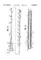
- FIG. 1is an elevational view, partially in section, of a catheter assembly embodying features of the invention.
- FIG. 2is a transverse cross-sectional view of the assembly shown in FIG. 1, taken along the lines 2--2.
- FIG. 3is an enlarged view of the distal end of the catheter assembly within a patient's artery with the balloon in an inflated condition to occlude the artery.
- FIG. 3Ais an enlarged view of the distal end of the catheter assembly within a patient's vein with the balloon in an inflated condition to occlude the vein.
- FIG. 4is an elevational view, partially in section, of a electrophysiology device which may be utilized to detect arrhythmogenic sites.
- FIG. 5is a longitudinal cross-sectional view of the distal portion of the electrophysiology member shown in FIG. 4
- FIG. 6is a longitudinal cross-sectional view of the electrophysiology member shown in FIG. 4 taken along the lines 6--6.
- FIG. 7is a transverse cross-sectional view of the electrophysiology member shown in FIG. 4 taken along the lines 7--7.
- FIG. 8is a longitudinal cross-sectional view of the proximal portion of the electrophysiology member shown in FIG. 4 taken along the lines 8--8.
- the catheter assembly of a presently preferred embodiment of the inventionincludes a catheter 10 and a guiding member 11, e.g. a guidewire, over which the catheter is advanced within a patient's vascular system.
- the catheter 10has a shaft 12 with a distal portion 13, a proximal portion 14 and an adapter 15 on the proximal end of the catheter shaft.
- the catheter shaft 12has a first inner lumen 16 configured to slidably receive the elongated guiding member 11 which extends from the proximal end of the shaft 12 to port 17 in the distal end of the catheter shaft and a second inner lumen 18 which extends from the proximal end to a location proximal to the distal end of the catheter shaft.
- the working length of the balloon 20is indicated by L.
- the adapter 15 on the proximal end of the catheter shaft 12has a side arm 21 which is in fluid communication with second inner lumen 18 and a central arm 22 which is in fluid communication with the first inner lumen 16.
- the guiding member 11may be a conventional guidewire as depicted in FIGS. 1-3 with a core member 25, a tapered distal section 26 disposed within helical coil 27.
- the distal end of the coil 27is secured to the distal end of the tapered distal section 26 by means of solder, brazing, welding and the like to form the rounded plug 28.
- the proximal end of the coil 27is secured in a similar manner to the core member 25 at a proximal location 29.
- the distal portion of the tapered section 26is typically flatted into a rectangular transverse cross-section to provide increased flexibility in one direction.
- the catheter 10is shown disposed within an arterial passageway 30 with the balloon 20 in an inflated condition to its working diameter so as to occlude the passageway.
- the inflated balloon 20contacts and slightly expands the artery wall 31.
- a body of blood 32is disposed within the arterial passageway 30 proximal to the balloon 20 resulting from the occlusion by the inflated balloon and lysing medium 33 is discharged from the distal end of the catheter 10 through port 17 into passageway 30 distal to the balloon.
- the lysing mediumis introduced into the first inner lumen 16 of catheter 10 through the center arm 21 of adapter 15.
- a suitable lysing mediumis a solution of ethanol (e.g. 50% by vol. or greater).
- a radiopaque marker 34is provided on the shaft distal to the balloon 20 to facilitate fluoroscopic determination of balloon location during the procedure.
- the blood vessel shownis a cardiac vein 35 with a body 36 of venous blood distal to the inflated balloon 20 within the venous passageway 37.
- the reference numbers used in this figureare otherwise the same as in FIG. 3
- An electrophysiological device 40may be used to detect electrical activity causing or involved with the arrhythmia from within the patient's coronary arteries or cardiac veins. This device is described and claimed in copending application Ser. No. 08/188,619, filed on Jan. 27, 1994, and which has been incorporated herein by reference.
- the electrophysiological device 40has a plurality of sensing electrodes 41 disposed on the distal portion 42 in pairs 43 for bipolar mode detection of electrical activity. Details of the distal portion 42 are shown in FIGS. 5 and 7.
- the shaft 44is formed of a braided tubular member 45 formed of a plurality of electrical conductors 46.
- the insulation on separate conductors 46is exposed under each of the sensing electrodes 41 so that an electrical connection can be made between the electrodes and the electrical conductors.
- the electrical connectionmay be secured by means of a suitable solder or brazing material, or by resistance welding, and the electrodes may also be secured to the underlying tubular member by a suitable means such as an adhesive to ensure maintenance of electrical contact with the exposed conductors.
- All of the strands of the braided tubular member 45need not be conductors and may be formed of polymer materials such as nylon.
- a polymer jacket 47is disposed about the braided tubular member 45 to provide a smoother exterior surface to the device. Suitable polymer materials for the jacket 47 include a high density polyethylene, a thermoplastic polyurethane, polyvinyl chloride, a polyolefinic ionamers such as Surlyn®. Other polymers may also be employed.
- a core member 50is disposed within the inner lumen of the braided tubular member 45 and extends beyond the distal end thereof.
- a distal coil 51is disposed about and secured by suitable means, such as brazing, soldering or an appropriate adhesive, to the distal extremity of the core member 50 and is provided with a smooth rounded distal tip 52 formed by joining the distal tip of the coil 51 to the distal extremity of the core member 50.
- the core 50may be formed of suitable metallic materials such as stainless steel. Other materials are contemplated.
- the proximal section 53 of the device 40 as shown in FIG. 4has two extensions 54 and 55 which have multi-pin connectors 56 and 57 on the proximal ends thereof. Details of the connector 56 is depicted in FIG. 8. While not shown, each of the electrical conductors 46 are electrically connected to a separate pin 58. A sixteen pin connector is schematically shown in FIG. 8 but connectors having a higher or lower number of pins may be suitable. The electrical conductors 46 are bundled together within the center of the extension.
- the electrophysiology device 40may be used independently of the occluding catheter 10, in which case the device is advanced through the patient's blood vessel to several locations therein to detect electrical activity and from this electrical activity determine the vascular location close to the origination or pathway tissue. The location is noted and the device 40 may then be removed.
- the device 40can be advanced through the venous side such as through the patients coronary sinus into the great cardiac vein or other veins which lead to the coronary sinus and the great vein or it can be advanced through the patient's coronary arteries. Once the electrophysiology device is removed, the guidewire 11 and catheter 10 as shown in FIGS.
- the occluding balloon 20 of the catheter 10can be advanced into the veins or arteries of the patient's heart in a conventional manner until the occluding balloon 20 of the catheter 10 is disposed within a blood vessel (artery or vein) at a location in which the inner diameter thereof has been determined and which is in close proximity to and in fluid communication with the tissue involved with the arrhythmia.
- the occluding balloon 20may then be inflated to the approximate inner diameter of the blood vessel at the selected location and the lysing medium discharged from the port 17 of the catheter 10 as described above.
- the iced salinemay be first discharged to paralyze the tissue distal to the catheter. If the arrhythmia is terminated by the delivery of the iced saline, the physician is reasonably assured that the arrhythmia will be permanently terminated by the delivery of the lysing medium to the same location.
- the electrophysiology device 40is used as a guidewire where the catheter is slidably mounted onto the device 40 before it is introduced into the patient's vasculature. Both the device 40 and the catheter 10 are then advanced through the vasculature with the distal portion 42 of the device extending out the distal end of the catheter 10 so as to detect electrical activity involved with the arrhythmia. When the arrhythmogenic site or pathway is located, the catheter 10 can then be suitably advanced over the device 40 until the balloon 20 is disposed in a vascular location in fluid communication with the arrhythmogenic or pathway tissue. Inflation of the balloon occludes the vascular passageway 30 and lysing medium can be discharged from the distal port 17 to lyse tissue involve with the arrhythmia. In this instance the electrophysiology device 40 is longer than the catheter 10 and is preferably about 25 to about 75 cm longer than the catheter.
Landscapes
- Health & Medical Sciences (AREA)
- Life Sciences & Earth Sciences (AREA)
- Heart & Thoracic Surgery (AREA)
- Engineering & Computer Science (AREA)
- Biomedical Technology (AREA)
- Veterinary Medicine (AREA)
- Public Health (AREA)
- General Health & Medical Sciences (AREA)
- Animal Behavior & Ethology (AREA)
- Pulmonology (AREA)
- Surgery (AREA)
- Anesthesiology (AREA)
- Biophysics (AREA)
- Child & Adolescent Psychology (AREA)
- Hematology (AREA)
- Vascular Medicine (AREA)
- Chemical Kinetics & Catalysis (AREA)
- General Chemical & Material Sciences (AREA)
- Physics & Mathematics (AREA)
- Plasma & Fusion (AREA)
- Nuclear Medicine, Radiotherapy & Molecular Imaging (AREA)
- Otolaryngology (AREA)
- Chemical & Material Sciences (AREA)
- Medical Informatics (AREA)
- Molecular Biology (AREA)
- Surgical Instruments (AREA)
- Media Introduction/Drainage Providing Device (AREA)
Abstract
Description
Claims (8)
Priority Applications (5)
| Application Number | Priority Date | Filing Date | Title |
|---|---|---|---|
| US08/695,986US5766152A (en) | 1996-08-15 | 1996-08-15 | Intraluminal delivery of tissue lysing medium |
| EP97937192AEP0925086A1 (en) | 1996-08-15 | 1997-08-11 | Intraluminal delivery of tissue lysing medium |
| AU39762/97AAU3976297A (en) | 1996-08-15 | 1997-08-11 | Intraluminal delivery of tissue lysing medium |
| PCT/US1997/014071WO1998006451A1 (en) | 1996-08-15 | 1997-08-11 | Intraluminal delivery of tissue lysing medium |
| US09/023,168US5947952A (en) | 1996-08-15 | 1998-02-13 | Intraluminal delivery of tissue lysing medium |
Applications Claiming Priority (1)
| Application Number | Priority Date | Filing Date | Title |
|---|---|---|---|
| US08/695,986US5766152A (en) | 1996-08-15 | 1996-08-15 | Intraluminal delivery of tissue lysing medium |
Related Child Applications (1)
| Application Number | Title | Priority Date | Filing Date |
|---|---|---|---|
| US09/023,168ContinuationUS5947952A (en) | 1996-08-15 | 1998-02-13 | Intraluminal delivery of tissue lysing medium |
Publications (1)
| Publication Number | Publication Date |
|---|---|
| US5766152Atrue US5766152A (en) | 1998-06-16 |
Family
ID=24795254
Family Applications (2)
| Application Number | Title | Priority Date | Filing Date |
|---|---|---|---|
| US08/695,986Expired - LifetimeUS5766152A (en) | 1996-08-15 | 1996-08-15 | Intraluminal delivery of tissue lysing medium |
| US09/023,168Expired - LifetimeUS5947952A (en) | 1996-08-15 | 1998-02-13 | Intraluminal delivery of tissue lysing medium |
Family Applications After (1)
| Application Number | Title | Priority Date | Filing Date |
|---|---|---|---|
| US09/023,168Expired - LifetimeUS5947952A (en) | 1996-08-15 | 1998-02-13 | Intraluminal delivery of tissue lysing medium |
Country Status (4)
| Country | Link |
|---|---|
| US (2) | US5766152A (en) |
| EP (1) | EP0925086A1 (en) |
| AU (1) | AU3976297A (en) |
| WO (1) | WO1998006451A1 (en) |
Cited By (29)
| Publication number | Priority date | Publication date | Assignee | Title |
|---|---|---|---|---|
| US6283947B1 (en) | 1999-07-13 | 2001-09-04 | Advanced Cardiovascular Systems, Inc. | Local drug delivery injection catheter |
| US20020173785A1 (en)* | 2000-03-31 | 2002-11-21 | Medtronic, Inc. | System and method for positioning implantable medical devices within coronary veins |
| US20020177847A1 (en)* | 2001-03-30 | 2002-11-28 | Long Gary L. | Endoscopic ablation system with flexible coupling |
| US20020183739A1 (en)* | 2001-03-30 | 2002-12-05 | Long Gary L. | Endoscopic ablation system with sealed sheath |
| US6494862B1 (en) | 1999-07-13 | 2002-12-17 | Advanced Cardiovascular Systems, Inc. | Substance delivery apparatus and a method of delivering a therapeutic substance to an anatomical passageway |
| US6585716B2 (en) | 2000-04-05 | 2003-07-01 | Biocardia, Inc. | Method of treating the heart |
| US20030181905A1 (en)* | 2002-03-25 | 2003-09-25 | Long Gary L. | Endoscopic ablation system with a distally mounted image sensor |
| US20030181900A1 (en)* | 2002-03-25 | 2003-09-25 | Long Gary L. | Endoscopic ablation system with a plurality of electrodes |
| US20030216727A1 (en)* | 2001-03-30 | 2003-11-20 | Long Gary L. | Medical device with improved wall construction |
| US20040082947A1 (en)* | 2002-10-25 | 2004-04-29 | The Regents Of The University Of Michigan | Ablation catheters |
| US6733500B2 (en) | 2000-03-31 | 2004-05-11 | Medtronic, Inc. | Method and system for delivering a medical electrical lead within a venous system |
| US6743227B2 (en) | 2000-03-31 | 2004-06-01 | Medtronic, Inc. | Intraluminal visualization system with deflectable mechanism |
| US6836687B2 (en) | 2000-03-31 | 2004-12-28 | Medtronic, Inc. | Method and system for delivery of a medical electrical lead within a venous system |
| US20050283939A1 (en)* | 2004-06-25 | 2005-12-29 | The Hoover Company | Handle assembly for a cleaning apparatus |
| US20060155935A1 (en)* | 1999-10-01 | 2006-07-13 | Jones Andrew M | System and method for maintaining cache coherency in a shared memory system |
| US7232438B2 (en) | 2004-07-09 | 2007-06-19 | Ethicon Endo-Surgery, Inc. | Ablation device with clear probe |
| US20080161803A1 (en)* | 2002-10-25 | 2008-07-03 | The Regents Of The University Of Michigan | Ablation Catheters And Methods For Their Use |
| US7850685B2 (en) | 2005-06-20 | 2010-12-14 | Medtronic Ablation Frontiers Llc | Ablation catheter |
| US8052668B2 (en) | 2005-05-13 | 2011-11-08 | Cardiac Pacemakers, Inc. | Neurotoxic agents and devices to treat atrial fibrillation |
| US8273084B2 (en) | 2004-11-24 | 2012-09-25 | Medtronic Ablation Frontiers Llc | Atrial ablation catheter and method of use |
| US8486063B2 (en) | 2004-10-14 | 2013-07-16 | Medtronic Ablation Frontiers Llc | Ablation catheter |
| US8617152B2 (en) | 2004-11-15 | 2013-12-31 | Medtronic Ablation Frontiers Llc | Ablation system with feedback |
| US8641704B2 (en) | 2007-05-11 | 2014-02-04 | Medtronic Ablation Frontiers Llc | Ablation therapy system and method for treating continuous atrial fibrillation |
| US8657814B2 (en) | 2005-08-22 | 2014-02-25 | Medtronic Ablation Frontiers Llc | User interface for tissue ablation system |
| US8834461B2 (en) | 2005-07-11 | 2014-09-16 | Medtronic Ablation Frontiers Llc | Low power tissue ablation system |
| US9005194B2 (en) | 2004-11-24 | 2015-04-14 | Medtronic Ablation Frontiers Llc | Atrial ablation catheter adapted for treatment of septal wall arrhythmogenic foci and method of use |
| US9254211B2 (en)* | 2005-10-06 | 2016-02-09 | Cordis Corporation | Stent delivery system using a steerable guide wire |
| CN107073245A (en)* | 2014-10-08 | 2017-08-18 | 日本来富恩株式会社 | Chemical ablation device and chemical ablation system |
| CN107280714A (en)* | 2017-06-27 | 2017-10-24 | 李毅刚 | Blood vessel intervention diagnosis and therapy system |
Families Citing this family (4)
| Publication number | Priority date | Publication date | Assignee | Title |
|---|---|---|---|---|
| EP0979635A2 (en) | 1998-08-12 | 2000-02-16 | Origin Medsystems, Inc. | Tissue dissector apparatus |
| US6558313B1 (en) | 2000-11-17 | 2003-05-06 | Embro Corporation | Vein harvesting system and method |
| JP2003175110A (en)* | 2001-12-07 | 2003-06-24 | Kanegafuchi Chem Ind Co Ltd | Balloon catheter and method for manufacturing the same |
| US9770230B2 (en) | 2006-06-01 | 2017-09-26 | Maquet Cardiovascular Llc | Endoscopic vessel harvesting system components |
Citations (7)
| Publication number | Priority date | Publication date | Assignee | Title |
|---|---|---|---|---|
| US4689041A (en)* | 1984-01-20 | 1987-08-25 | Eliot Corday | Retrograde delivery of pharmacologic and diagnostic agents via venous circulation |
| US4850969A (en)* | 1987-10-01 | 1989-07-25 | Retroperfusion Systems, Inc. | Retroperfusion catheter and tip construction for use therewith |
| US5143093A (en)* | 1990-10-05 | 1992-09-01 | Harvinder Sahota | Methods of angioplasty treatment of stenotic regions |
| US5158529A (en)* | 1990-03-29 | 1992-10-27 | Aisin Seiki Kabushiki Kaisha | Pumping device for operating an intra-aortic balloon |
| US5279560A (en)* | 1988-11-10 | 1994-01-18 | C. R. Bard, Inc. | Balloon dilatation catheter with integral guidewire |
| US5429605A (en)* | 1994-01-26 | 1995-07-04 | Target Therapeutics, Inc. | Microballoon catheter |
| US5486192A (en)* | 1994-06-03 | 1996-01-23 | Walinsky; Paul | Cyclic coronary angioplasty system |
Family Cites Families (6)
| Publication number | Priority date | Publication date | Assignee | Title |
|---|---|---|---|---|
| US5250069A (en)* | 1987-02-27 | 1993-10-05 | Terumo Kabushiki Kaisha | Catheter equipped with expansible member and production method thereof |
| US5290306A (en)* | 1989-11-29 | 1994-03-01 | Cordis Corporation | Puncture resistant balloon catheter |
| US5053008A (en)* | 1990-11-21 | 1991-10-01 | Sandeep Bajaj | Intracardiac catheter |
| US5699796A (en) | 1993-01-29 | 1997-12-23 | Cardima, Inc. | High resolution intravascular signal detection |
| US5706809A (en) | 1993-01-29 | 1998-01-13 | Cardima, Inc. | Method and system for using multiple intravascular sensing devices to detect electrical activity |
| WO1995029729A1 (en)* | 1994-04-29 | 1995-11-09 | Boston Scientific Corporation | Novel micro occlusion balloon catheter |
- 1996
- 1996-08-15USUS08/695,986patent/US5766152A/ennot_activeExpired - Lifetime
- 1997
- 1997-08-11EPEP97937192Apatent/EP0925086A1/ennot_activeWithdrawn
- 1997-08-11WOPCT/US1997/014071patent/WO1998006451A1/ennot_activeApplication Discontinuation
- 1997-08-11AUAU39762/97Apatent/AU3976297A/ennot_activeAbandoned
- 1998
- 1998-02-13USUS09/023,168patent/US5947952A/ennot_activeExpired - Lifetime
Patent Citations (7)
| Publication number | Priority date | Publication date | Assignee | Title |
|---|---|---|---|---|
| US4689041A (en)* | 1984-01-20 | 1987-08-25 | Eliot Corday | Retrograde delivery of pharmacologic and diagnostic agents via venous circulation |
| US4850969A (en)* | 1987-10-01 | 1989-07-25 | Retroperfusion Systems, Inc. | Retroperfusion catheter and tip construction for use therewith |
| US5279560A (en)* | 1988-11-10 | 1994-01-18 | C. R. Bard, Inc. | Balloon dilatation catheter with integral guidewire |
| US5158529A (en)* | 1990-03-29 | 1992-10-27 | Aisin Seiki Kabushiki Kaisha | Pumping device for operating an intra-aortic balloon |
| US5143093A (en)* | 1990-10-05 | 1992-09-01 | Harvinder Sahota | Methods of angioplasty treatment of stenotic regions |
| US5429605A (en)* | 1994-01-26 | 1995-07-04 | Target Therapeutics, Inc. | Microballoon catheter |
| US5486192A (en)* | 1994-06-03 | 1996-01-23 | Walinsky; Paul | Cyclic coronary angioplasty system |
Non-Patent Citations (2)
| Title |
|---|
| Angelo A.V. De Paola, MC, et al., Transcoronary Chemical Ablation of Ventricular Tachycardia in Chronic Chagasic Myocarditis, American College of Cardiology, vol. 20:480 482, Aug. 1992.* |
| Angelo A.V. De Paola, MC, et al., Transcoronary Chemical Ablation of Ventricular Tachycardia in Chronic Chagasic Myocarditis, American College of Cardiology, vol. 20:480-482, Aug. 1992. |
Cited By (52)
| Publication number | Priority date | Publication date | Assignee | Title |
|---|---|---|---|---|
| US6689099B2 (en) | 1999-07-13 | 2004-02-10 | Advanced Cardiovascular Systems, Inc. | Local drug delivery injection catheter |
| US6283947B1 (en) | 1999-07-13 | 2001-09-04 | Advanced Cardiovascular Systems, Inc. | Local drug delivery injection catheter |
| US7150738B2 (en) | 1999-07-13 | 2006-12-19 | Advanced Cardiovascular Systems, Inc. | Substance delivery apparatus and a method of delivering a therapeutic substance to an anatomical passageway |
| US6494862B1 (en) | 1999-07-13 | 2002-12-17 | Advanced Cardiovascular Systems, Inc. | Substance delivery apparatus and a method of delivering a therapeutic substance to an anatomical passageway |
| US20030040712A1 (en)* | 1999-07-13 | 2003-02-27 | Pinaki Ray | Substance delivery apparatus and a method of delivering a therapeutic substance to an anatomical passageway |
| US20060155935A1 (en)* | 1999-10-01 | 2006-07-13 | Jones Andrew M | System and method for maintaining cache coherency in a shared memory system |
| US10328243B2 (en) | 2000-03-31 | 2019-06-25 | Medtronic, Inc. | System and method for positioning implantable medical devices within coronary veins |
| US6743227B2 (en) | 2000-03-31 | 2004-06-01 | Medtronic, Inc. | Intraluminal visualization system with deflectable mechanism |
| US7497844B2 (en) | 2000-03-31 | 2009-03-03 | Medtronic, Inc. | System and method for positioning implantable medical devices within coronary veins |
| US20020173785A1 (en)* | 2000-03-31 | 2002-11-21 | Medtronic, Inc. | System and method for positioning implantable medical devices within coronary veins |
| US8734397B2 (en) | 2000-03-31 | 2014-05-27 | Medtronic, Inc. | System and method for positioning implantable medical devices within coronary veins |
| US6836687B2 (en) | 2000-03-31 | 2004-12-28 | Medtronic, Inc. | Method and system for delivery of a medical electrical lead within a venous system |
| US20090131873A1 (en)* | 2000-03-31 | 2009-05-21 | Medtronic, Inc. | System and method for positioning implantable medical devices within coronary veins |
| US6733500B2 (en) | 2000-03-31 | 2004-05-11 | Medtronic, Inc. | Method and system for delivering a medical electrical lead within a venous system |
| US20040030286A1 (en)* | 2000-04-05 | 2004-02-12 | Biocardia, Inc. | Method of treating the heart |
| US6585716B2 (en) | 2000-04-05 | 2003-07-01 | Biocardia, Inc. | Method of treating the heart |
| US8388581B2 (en) | 2000-04-05 | 2013-03-05 | Biocardia, Inc. | System for treating the heart with potentially embolic agents through a right heart approach |
| US6918906B2 (en) | 2001-03-30 | 2005-07-19 | Gary L. Long | Endoscopic ablation system with improved electrode geometry |
| US20020183739A1 (en)* | 2001-03-30 | 2002-12-05 | Long Gary L. | Endoscopic ablation system with sealed sheath |
| US7097644B2 (en) | 2001-03-30 | 2006-08-29 | Ethicon Endo-Surgery, Inc. | Medical device with improved wall construction |
| US20020177847A1 (en)* | 2001-03-30 | 2002-11-28 | Long Gary L. | Endoscopic ablation system with flexible coupling |
| US20030216727A1 (en)* | 2001-03-30 | 2003-11-20 | Long Gary L. | Medical device with improved wall construction |
| US20030181905A1 (en)* | 2002-03-25 | 2003-09-25 | Long Gary L. | Endoscopic ablation system with a distally mounted image sensor |
| US7137981B2 (en) | 2002-03-25 | 2006-11-21 | Ethicon Endo-Surgery, Inc. | Endoscopic ablation system with a distally mounted image sensor |
| US20030181900A1 (en)* | 2002-03-25 | 2003-09-25 | Long Gary L. | Endoscopic ablation system with a plurality of electrodes |
| US7857808B2 (en) | 2002-10-25 | 2010-12-28 | The Regents Of The University Of Michigan | Ablation catheters |
| US20080161803A1 (en)* | 2002-10-25 | 2008-07-03 | The Regents Of The University Of Michigan | Ablation Catheters And Methods For Their Use |
| US7993333B2 (en) | 2002-10-25 | 2011-08-09 | The Regents Of The University Of Michigan | Ablation catheters |
| US20040082947A1 (en)* | 2002-10-25 | 2004-04-29 | The Regents Of The University Of Michigan | Ablation catheters |
| US20050283939A1 (en)* | 2004-06-25 | 2005-12-29 | The Hoover Company | Handle assembly for a cleaning apparatus |
| US7232438B2 (en) | 2004-07-09 | 2007-06-19 | Ethicon Endo-Surgery, Inc. | Ablation device with clear probe |
| US8486063B2 (en) | 2004-10-14 | 2013-07-16 | Medtronic Ablation Frontiers Llc | Ablation catheter |
| US9642675B2 (en) | 2004-10-14 | 2017-05-09 | Medtronic Ablation Frontiers Llc | Ablation catheter |
| US8617152B2 (en) | 2004-11-15 | 2013-12-31 | Medtronic Ablation Frontiers Llc | Ablation system with feedback |
| US9005194B2 (en) | 2004-11-24 | 2015-04-14 | Medtronic Ablation Frontiers Llc | Atrial ablation catheter adapted for treatment of septal wall arrhythmogenic foci and method of use |
| US8273084B2 (en) | 2004-11-24 | 2012-09-25 | Medtronic Ablation Frontiers Llc | Atrial ablation catheter and method of use |
| US8585641B2 (en) | 2005-05-13 | 2013-11-19 | Cardiac Pacemakers, Inc. | Neurotoxic agents and medical devices therefor |
| US8052668B2 (en) | 2005-05-13 | 2011-11-08 | Cardiac Pacemakers, Inc. | Neurotoxic agents and devices to treat atrial fibrillation |
| US7850685B2 (en) | 2005-06-20 | 2010-12-14 | Medtronic Ablation Frontiers Llc | Ablation catheter |
| US8771267B2 (en) | 2005-06-20 | 2014-07-08 | Medtronic Ablation Frontiers Llc | Ablation catheter |
| US8337492B2 (en) | 2005-06-20 | 2012-12-25 | Medtronic Ablation Frontiers Llc | Ablation catheter |
| US9468495B2 (en) | 2005-06-20 | 2016-10-18 | Medtronic Ablation Frontiers Llc | Ablation catheter |
| US8979841B2 (en) | 2005-06-20 | 2015-03-17 | Medtronic Ablation Frontiers Llc | Ablation catheter |
| US9566113B2 (en) | 2005-07-11 | 2017-02-14 | Medtronic Ablation Frontiers Llc | Low power tissue ablation system |
| US8834461B2 (en) | 2005-07-11 | 2014-09-16 | Medtronic Ablation Frontiers Llc | Low power tissue ablation system |
| US8657814B2 (en) | 2005-08-22 | 2014-02-25 | Medtronic Ablation Frontiers Llc | User interface for tissue ablation system |
| US9254211B2 (en)* | 2005-10-06 | 2016-02-09 | Cordis Corporation | Stent delivery system using a steerable guide wire |
| US8771269B2 (en) | 2007-05-11 | 2014-07-08 | Medtronic Ablation Frontiers Llc | RF energy delivery system and method |
| US10219857B2 (en) | 2007-05-11 | 2019-03-05 | Medtronic Ablation Frontiers Llc | RF energy delivery system |
| US8641704B2 (en) | 2007-05-11 | 2014-02-04 | Medtronic Ablation Frontiers Llc | Ablation therapy system and method for treating continuous atrial fibrillation |
| CN107073245A (en)* | 2014-10-08 | 2017-08-18 | 日本来富恩株式会社 | Chemical ablation device and chemical ablation system |
| CN107280714A (en)* | 2017-06-27 | 2017-10-24 | 李毅刚 | Blood vessel intervention diagnosis and therapy system |
Also Published As
| Publication number | Publication date |
|---|---|
| US5947952A (en) | 1999-09-07 |
| AU3976297A (en) | 1998-03-06 |
| EP0925086A1 (en) | 1999-06-30 |
| WO1998006451A1 (en) | 1998-02-19 |
Similar Documents
| Publication | Publication Date | Title |
|---|---|---|
| US5766152A (en) | Intraluminal delivery of tissue lysing medium | |
| US5782760A (en) | Over-the-wire EP catheter | |
| US6002956A (en) | Method of treating using an over-the-wire EP catheter | |
| EP1011437B1 (en) | Over-the-wire electrophysiology catheter | |
| US5775327A (en) | Guiding catheter for the coronary sinus | |
| CA2154773C (en) | Intravascular sensing device | |
| US5645064A (en) | High resolution intravascular signal detection | |
| US6120499A (en) | Intravascular RF occlusion catheter | |
| CA2154774C (en) | Multiple intravascular sensing devices for electrical activity | |
| WO1998038912A9 (en) | Over-the-wire ep catheter | |
| US6113584A (en) | Intraluminal delivery of tissue lysing medium | |
| KR20210144506A (en) | RF ablation catheter for Septal reduction theraphy having cooling effect |
Legal Events
| Date | Code | Title | Description |
|---|---|---|---|
| AS | Assignment | Owner name:NEW ENGLAND MEDICAL CENTER HOSPITALS, INC., MASSAC Free format text:ASSIGNMENT OF ASSIGNORS INTEREST;ASSIGNOR:WANG, PAUL J.;REEL/FRAME:008425/0280 Effective date:19970220 Owner name:CARDIMA, INC., CALIFORNIA Free format text:ASSIGNMENT OF ASSIGNORS INTEREST;ASSIGNOR:MORLEY, TRACEY A.;REEL/FRAME:008429/0562 Effective date:19970217 Owner name:CARDIMA, INC., CALIFORNIA Free format text:ASSIGNMENT OF ASSIGNORS INTEREST;ASSIGNOR:NEW ENGLAND MEDICAL HOSPITALS, INC.;REEL/FRAME:008427/0622 Effective date:19970319 | |
| AS | Assignment | Owner name:CARDIMA, INC., CALIFORNIA Free format text:ASSIGNMENT OF ASSIGNORS INTEREST;ASSIGNOR:NEW ENGLAND MEDICAL HOSPITALS, INC.;REEL/FRAME:008695/0386 Effective date:19970722 | |
| STCF | Information on status: patent grant | Free format text:PATENTED CASE | |
| AS | Assignment | Owner name:TRANSAMERICA BUSINESS CREDIT CORP., CONNECTICUT Free format text:ASSIGNMENT OF ASSIGNORS INTEREST;ASSIGNOR:CARDIMA, INC.;REEL/FRAME:009392/0236 Effective date:19980619 | |
| FPAY | Fee payment | Year of fee payment:4 | |
| AS | Assignment | Owner name:AGILITY CAPITAL LLC, CALIFORNIA Free format text:INTELLECTUAL PROPERTY SECURITY AGREEMENT;ASSIGNOR:CARDIMA, INC.;REEL/FRAME:016050/0334 Effective date:20050523 | |
| AS | Assignment | Owner name:CARDIMA, INC., CALIFORNIA Free format text:TERMINATION OF PATENT AND TRADEMARK SECURITY AGREEMENT;ASSIGNOR:TRANSAMERICA BUSINESS CREDIT CORPORATION;REEL/FRAME:016050/0849 Effective date:20001208 | |
| AS | Assignment | Owner name:CARDIMA, INC., CALIFORNIA Free format text:TERMINATION OF PATENT SECURITY INTEREST;ASSIGNOR:AGILITY CAPITAL, LLC;REEL/FRAME:016397/0200 Effective date:20050812 | |
| AS | Assignment | Owner name:APIX INTERNATIONAL LIMITED, CHINA Free format text:SECURITY AGREEMENT;ASSIGNOR:CARDIMA, INC.;REEL/FRAME:016418/0738 Effective date:20050811 | |
| FPAY | Fee payment | Year of fee payment:8 | |
| FEPP | Fee payment procedure | Free format text:PAYER NUMBER DE-ASSIGNED (ORIGINAL EVENT CODE: RMPN); ENTITY STATUS OF PATENT OWNER: SMALL ENTITY Free format text:PAYOR NUMBER ASSIGNED (ORIGINAL EVENT CODE: ASPN); ENTITY STATUS OF PATENT OWNER: SMALL ENTITY | |
| FPAY | Fee payment | Year of fee payment:12 | |
| AS | Assignment | Owner name:RUI XING LIMITED, HONG KONG Free format text:ASSIGNMENT OF ASSIGNORS INTEREST;ASSIGNOR:CARDIMA, INC.;REEL/FRAME:026287/0523 Effective date:20110331 | |
| AS | Assignment | Owner name:SICHUAN JINJIANG ELECTRONIC SCIENCE AND TECHNOLOGY Free format text:ASSIGNMENT OF ASSIGNORS INTEREST;ASSIGNOR:RUI XING LTD.;REEL/FRAME:031011/0955 Effective date:20130809 |