US5765559A - Multi-cuffed endotracheal tube and method of its use - Google Patents
Multi-cuffed endotracheal tube and method of its useDownload PDFInfo
- Publication number
- US5765559A US5765559AUS08/637,396US63739696AUS5765559AUS 5765559 AUS5765559 AUS 5765559AUS 63739696 AUS63739696 AUS 63739696AUS 5765559 AUS5765559 AUS 5765559A
- Authority
- US
- United States
- Prior art keywords
- cuff
- trachea
- rings
- endotracheal tube
- inflated
- Prior art date
- Legal status (The legal status is an assumption and is not a legal conclusion. Google has not performed a legal analysis and makes no representation as to the accuracy of the status listed.)
- Expired - Fee Related
Links
- 238000000034methodMethods0.000titleclaimsdescription21
- 210000003437tracheaAnatomy0.000claimsabstractdescription97
- 238000002627tracheal intubationMethods0.000abstractdescription17
- 238000005299abrasionMethods0.000abstractdescription5
- 230000000737periodic effectEffects0.000abstractdescription3
- 239000000314lubricantSubstances0.000description13
- 230000001050lubricating effectEffects0.000description13
- 230000001105regulatory effectEffects0.000description8
- 210000004072lungAnatomy0.000description7
- 238000005461lubricationMethods0.000description6
- 238000003780insertionMethods0.000description5
- 230000037431insertionEffects0.000description5
- 238000010586diagramMethods0.000description4
- 230000033001locomotionEffects0.000description4
- 239000000463materialSubstances0.000description4
- 229920000915polyvinyl chloridePolymers0.000description4
- 239000004800polyvinyl chlorideSubstances0.000description4
- 230000002035prolonged effectEffects0.000description4
- 238000001356surgical procedureMethods0.000description4
- 210000001519tissueAnatomy0.000description4
- 239000002993sponge (artificial)Substances0.000description3
- 206010010071ComaDiseases0.000description2
- 241001465754MetazoaSpecies0.000description2
- 208000004756Respiratory InsufficiencyDiseases0.000description2
- 230000001154acute effectEffects0.000description2
- 238000005452bendingMethods0.000description2
- 230000017531blood circulationEffects0.000description2
- 210000004081ciliaAnatomy0.000description2
- 238000004891communicationMethods0.000description2
- 238000007796conventional methodMethods0.000description2
- 238000011065in-situ storageMethods0.000description2
- 210000000867larynxAnatomy0.000description2
- 230000017074necrotic cell deathEffects0.000description2
- 210000003800pharynxAnatomy0.000description2
- 230000008569processEffects0.000description2
- 230000009467reductionEffects0.000description2
- 230000002829reductive effectEffects0.000description2
- 201000004193respiratory failureDiseases0.000description2
- 238000009423ventilationMethods0.000description2
- 206010002091AnaesthesiaDiseases0.000description1
- 241000894006BacteriaSpecies0.000description1
- 241000282412HomoSpecies0.000description1
- 230000009471actionEffects0.000description1
- 230000002411adverseEffects0.000description1
- 230000037005anaesthesiaEffects0.000description1
- 239000003242anti bacterial agentSubstances0.000description1
- 230000001580bacterial effectEffects0.000description1
- 230000003115biocidal effectEffects0.000description1
- 230000006835compressionEffects0.000description1
- 238000007906compressionMethods0.000description1
- 238000004590computer programMethods0.000description1
- 230000003247decreasing effectEffects0.000description1
- 238000013461designMethods0.000description1
- 239000003814drugSubstances0.000description1
- 229940079593drugDrugs0.000description1
- 239000012530fluidSubstances0.000description1
- 230000006870functionEffects0.000description1
- 239000007789gasSubstances0.000description1
- 230000002496gastric effectEffects0.000description1
- 238000002695general anesthesiaMethods0.000description1
- 239000003193general anesthetic agentSubstances0.000description1
- 208000015181infectious diseaseDiseases0.000description1
- 230000000670limiting effectEffects0.000description1
- 238000003754machiningMethods0.000description1
- 239000012528membraneSubstances0.000description1
- 238000013508migrationMethods0.000description1
- 230000005012migrationEffects0.000description1
- 238000000465mouldingMethods0.000description1
- 238000004806packaging method and processMethods0.000description1
- 230000036961partial effectEffects0.000description1
- 230000000069prophylactic effectEffects0.000description1
- 230000028327secretionEffects0.000description1
- 208000006601tracheal stenosisDiseases0.000description1
- 210000005092tracheal tissueAnatomy0.000description1
Images


Classifications
- A—HUMAN NECESSITIES
- A61—MEDICAL OR VETERINARY SCIENCE; HYGIENE
- A61M—DEVICES FOR INTRODUCING MEDIA INTO, OR ONTO, THE BODY; DEVICES FOR TRANSDUCING BODY MEDIA OR FOR TAKING MEDIA FROM THE BODY; DEVICES FOR PRODUCING OR ENDING SLEEP OR STUPOR
- A61M16/00—Devices for influencing the respiratory system of patients by gas treatment, e.g. ventilators; Tracheal tubes
- A61M16/04—Tracheal tubes
- A61M16/0434—Cuffs
- A61M16/0443—Special cuff-wall materials
- A—HUMAN NECESSITIES
- A61—MEDICAL OR VETERINARY SCIENCE; HYGIENE
- A61M—DEVICES FOR INTRODUCING MEDIA INTO, OR ONTO, THE BODY; DEVICES FOR TRANSDUCING BODY MEDIA OR FOR TAKING MEDIA FROM THE BODY; DEVICES FOR PRODUCING OR ENDING SLEEP OR STUPOR
- A61M16/00—Devices for influencing the respiratory system of patients by gas treatment, e.g. ventilators; Tracheal tubes
- A61M16/04—Tracheal tubes
- A61M16/0434—Cuffs
- A61M16/0445—Special cuff forms, e.g. undulated
- A61M16/0447—Bell, canopy or umbrella shaped
- A—HUMAN NECESSITIES
- A61—MEDICAL OR VETERINARY SCIENCE; HYGIENE
- A61M—DEVICES FOR INTRODUCING MEDIA INTO, OR ONTO, THE BODY; DEVICES FOR TRANSDUCING BODY MEDIA OR FOR TAKING MEDIA FROM THE BODY; DEVICES FOR PRODUCING OR ENDING SLEEP OR STUPOR
- A61M16/00—Devices for influencing the respiratory system of patients by gas treatment, e.g. ventilators; Tracheal tubes
- A61M16/04—Tracheal tubes
- A61M16/0434—Cuffs
- A61M16/0454—Redundant cuffs
- A61M16/0459—Redundant cuffs one cuff behind another
- A—HUMAN NECESSITIES
- A61—MEDICAL OR VETERINARY SCIENCE; HYGIENE
- A61M—DEVICES FOR INTRODUCING MEDIA INTO, OR ONTO, THE BODY; DEVICES FOR TRANSDUCING BODY MEDIA OR FOR TAKING MEDIA FROM THE BODY; DEVICES FOR PRODUCING OR ENDING SLEEP OR STUPOR
- A61M25/00—Catheters; Hollow probes
- A61M25/10—Balloon catheters
- A61M25/1011—Multiple balloon catheters
- A—HUMAN NECESSITIES
- A61—MEDICAL OR VETERINARY SCIENCE; HYGIENE
- A61M—DEVICES FOR INTRODUCING MEDIA INTO, OR ONTO, THE BODY; DEVICES FOR TRANSDUCING BODY MEDIA OR FOR TAKING MEDIA FROM THE BODY; DEVICES FOR PRODUCING OR ENDING SLEEP OR STUPOR
- A61M25/00—Catheters; Hollow probes
- A61M25/10—Balloon catheters
- A61M25/1018—Balloon inflating or inflation-control devices
- A61M25/10181—Means for forcing inflation fluid into the balloon
- A61M25/10182—Injector syringes
Definitions
- the present inventionrelates generally to a multi-cuffed endotracheal tube for intubation of a trachea.
- the multi-cuffed endotracheal tuberelieves a trachea of the constant pressure exerted against it by the cuff of a conventional endotracheal tube when inserted into a patient's trachea either through the mouth, nose, or a tracheostomy.
- the inventionalso relates to a method of successive cycles of pressurization and depressurization of portions of a trachea during the course of an intubation procedure. It also relates to a method of lubricating the interface between the cuff and the inner wall of the trachea.
- Endotracheal intubationis an established procedure used to assure a patient's open airway during surgical procedures requiring general anesthesia. Intubation of the trachea also protects the airway from gastric contents, allows positive air pressure to be administered to the lungs, and permits suctioning of the tracheobronchial tree for removal of secretions. Intubation is indicated for the awake patient in respiratory failure or impending respiratory failure.
- the endotracheal tubeis generally inserted through a patient's mouth or nose and then into the trachea, but may also be directly inserted into the trachea through a tracheostomy.
- Cuffed endotracheal tubes 11are generally constructed of bio-compatible polyvinyl chloride and a low pressure, high volume cuff 19 as shown in FIG. 1A and 1B.
- FIG. 1Ashows the endotracheal tube 11 inserted through the patient's mouth and into the patient's trachea 35 with the cuff 19 in an inflated state as it would be during a surgical procedure. While not shown in FIG. 1A, the endotracheal tube can also be inserted through a tracheostomy.
- FIG. 1Bdepicts the endotracheal tube 11 outside the patient's trachea 35 with the cuff 19 inflated.
- FIG. 2shows the endotracheal tube 11 outside the patient.
- an endotracheal tube 11consists of a cannula 16 having a distal end 13, and a connector 14 at the proximal end 12.
- the endotracheal tube 11allows air to be forced into the lungs of a patient from the connector orifice 43 through the cannula 16 to the distal end 13 of the cannula 16.
- the cannula 16 near the distal end 13is surrounded by the cuff 19.
- the cuff 19is bonded to the cannula 16 circumferentially at both ends of the cuff 19 to provide an air tight seal.
- the cannula 16is provided with at least one cuff port 21 on that portion of the cannula 16 interior to the cuff 19.
- the cuff port 21is connected to the cuff inflation line 20 which extends from the cuff port 21 to beyond the connector 14 to provide adequate length for the physician to attach a syringe 26 to the end of the cuff inflation line 20 protruding from the patient's mouth, nose, or from a tracheostomy.
- That portion of the endotracheal tube 11 protruding from the patient's mouth, nose, or a tracheostomyhas affixed to it a valve 25 which is normally closed; opening only when air is injected into it by the syringe 26 or suctioned out by the syringe 26.
- the valve 25allows air to be forced into the cuff inflation line 20 by pushing the piston into the cylinder of the attached syringe 26, but will not allow the air to escape unless the syringe piston is retracted.
- the airUpon forcing air into the cuff inflation line with the syringe 26, the air enters the cuff 19 through the cuff port 21 and thereby inflates the cuff 19.
- the pilot balloon 24indicates inflation of the cuff 19 when the pilot balloon 24 is inflated.
- FIGS. 1A and 1Billustrate, after insertion of the endotracheal tube 11 into the patient's trachea 35, the cuff 19 is inflated to conform to the natural shape of the trachea 35 providing a relatively air tight seal between the endotracheal tube 11 and the trachea 35.
- Endotracheal intubation efficacyis well accepted.
- High-volume, low-pressure cuffsnow widely used, have decreased morbidity from intubation.
- serious adverse consequences from intubationstill exist, particularly from prolonged use.
- One studyreported tracheal stenosis in 19% of patient's that underwent prolonged tracheal intubation and in 65% that had undergone a tracheostomy. Some damage may be so severe that a portion of the trachea may have to be removed. See Complications and Consequences of Endotracheal Intubation and Tracheostomy, by Stauffer J. L., Olson D. E., and Petty, T. L., published in the American Journal of Medicine, 1981.
- the damageis due to the constant pressure exerted by the cuff 19 on the tracheal wall, especially during prolonged surgery, as well as the abrasion of the trachea by the cuff 19.
- the constant pressure of the cuff on the delicate tracheal wallmay damage the fine hair-like cilia lining the wall or may cut off the blood flow to the surface tissue of the trachea to such a degree that tissue necrosis results.
- the constant cuff 19 contactcan also result in bacteria build-up at the trachea-cuff margin, resulting in infection of that portion of the trachea and beyond.
- the cuff of the present inventionis illustrated and discussed primarily in combination with a cannula for endotracheal intubation of human patients. However, the multi-cuff of the present invention may also be used in combination with a cannula for intubation of the trachea of animals as well as humans.
- Thisallows for accomplishment of the primary objective of the endotracheal tube cuff 19, which is to seal off the area surrounding the endotracheal tube 11 between the tube 11 and the trachea 35.
- a further objective of the present inventionis accomplished by providing a means of lubricating the contact point between the cuff 19 and the trachea 35. Damage due to frictional abrasion between the tracheal wall 35 and the cuff 19 is thereby reduced. Frictional abrasion is caused by movement of the endotracheal tube 11 in the trachea 35 by medical personnel during the medical procedure requiring intubation.
- Yet another objective of the inventionis accomplished by introducing an amount of an antibiotic in a lubricating means 33 to help fight bacterial growth that is a natural concomitant of a foreign object in the trachea 35, a relatively immobile trachea due to the general anesthetic administered to the patient, and the reduced wave-like motion of the cilia due to the pressure of the cuff rings 27 against the trachea 35.
- An additional objective of the present inventionis to provide a means of limiting higher than acceptable pressure of the cuff against the tracheal wall caused by momentary over-inflation of the cuff rings 27 due to minor fluctuations in the regulated air supply 34 used to deliver the air pressure to the cuff rings 27 or an incorrect air pressure setting. This is accomplished by cuff rings 27 that are formed at an angle to the longitudinal axis 44 of the cannula 16.
- the combination of the strength of the material comprising the cuff rings 27 and the angle at which the cuff rings 27 contact the trachea 35allow the cuff rings 27 to deform and cover a larger surface area of the trachea 35, thereby reducing the pressure per unit of surface area of the trachea 35.
- Still another objective of the present inventionis to keep the airway above the cuff 19 or the cuff rings 27 free from fluid and other biological debris.
- the present inventionprovides a means for suctioning off this matter as needed.
- a further objective of the present inventionis to provide a cuff which maintains a constant seal between the trachea, whether human or other animal, and an inserted cannula without damaging the tracheal tissue due to uninterrupted pressure of the cuff on the tracheal wall.
- FIG. 1Ais a pictorial diagram of a conventional endotracheal tube in the trachea of a patient with the cuff inflated.
- FIG. 1Bis a pictorial diagram of a conventional endotracheal tube outside the patient with the cuff inflated.
- FIG. 2is a pictorial diagram of a conventional endotracheal tube before emplacement in a patient with the cuff deflated.
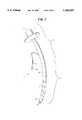
- FIG. 3is a pictorial diagram of the endotracheal tube of the present invention with the cuff rings inflated.
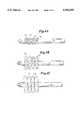
- FIG. 4illustrates three stages of inflation of the cuff rings.
- FIG. 5depicts the sequence of inflation of the cuff rings.
- FIG. 6is a detail of the cuff ring assembly and an illustration of the cuff ring assembly mounted on the cannula.
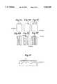
- FIG. 7presents alternate cuff ring embodiments in various states of inflation.
- FIG. 8is a representation of a cuff ring lubricant system.
- FIG. 9is a representation of an alternate embodiment of a cuff ring lubricant system.
- FIG. 10presents an alternate system of lubrication of a cuff or a cuff ring using lubrication depressions.
- FIGS. 1A and 1B of the drawingsshowing a conventional endotracheal tube 11.
- the tubeconsists of a proximal end 12 and a distal end 13.
- the proximal end 12is terminated in a connector 14 for connection to a regulated breathable air supply pump 15 for introduction of gases to the patient's 49 lungs to maintain positive pressure in the lungs to assist the patient 49 to breathe during the medical procedure being administered during endotracheal intubation.
- the endotracheal tube 11, which extends from the patient's mouth 45 and into the trachea 35is in the form of a cannula 16 having an open longitudinally extending interior referred herein as the lumen 17.
- the cannula 16is open at the distal end 13 forming the distal opening 18.
- the distal opening 18is often formed at an acute angle to the longitudinal axis of the cannula 16 rather than at a right angle to provide a larger open area and allow more easy machining of a soft rounded edge on the distal opening 18.
- the larger area of the distal opening 18helps to avoid obstruction of the lumen 17 while the rounded edge is meant to avoid tearing of the tissue through which the cannula 16 passes upon insertion of the endotracheal tube 11 into the patient.
- the narrow pointed cannula end 46also allows the cannula 16 to work its way through portions of the patient's larynx 47, pharynx 48, and trachea 35 that may be partially closed off.
- the cannula 16is generally constructed of radio-opaque bio-compatible polyvinyl chloride tubing having some small degree of flexibility.
- FIGS. 1A and 1Bshow the cuff 19 in a fully inflated state.
- FIG. 2shows a conventional endotracheal tube 11 with the cuff 19 in a deflated state.
- the cuff 19, like the cannula 16,is generally constructed of radio-opaque bio-compatible polyvinyl chloride, but of a very thin wall. The thin wall allows for inflation and deflation. When the cuff 16 is inflated, the cuff 16 conforms to the natural shape of the trachea 35 while providing the required seal by contact with the minimal area of tracheal wall.
- the cuff 16is both inflated and deflated through the cuff inflation line 20 which extends from the cuff port 21 to outside of the patient's mouth.
- the cuff port 21is a transverse opening in the side wall of the cannula 22 allowing communication from the lumen 17 to the inside of the cuff 19.
- the cuff inflation line 20is attached to the cuff port 21 using conventional bonding techniques.
- the inside diameter of the cuff inflation line 20is usually the same as the diameter of the cuff port 21.
- the cuff inflation line 20is bonded to the inside wall of the cannula 22 and exits the cannula near the connector 14 through the inflation line port 23.
- a pilot balloon 24is connected to indicate cuff 19 inflation.
- a valve 25attaches to the pilot balloon 24 and in turn is adapted to connect to a syringe 26 for expression of air into the cuff 19 or deflation of the cuff 19.
- the valve 25allows air to be expressed into the cuff inflation line 20, but closes so air is not allowed out. However, air can be suctioned out of the cuff inflation line 20 by the back pressure on the valve 25, which causes the valve 25 to open when the syringe plunger is pulled out of the syringe 26.
- the conventional endotracheal tube 11is inserted into the patient's mouth or nose, extended through the pharynx 48, then the larynx 47, and into the trachea 35.
- the tube 11is long enough that the connector 14 extends beyond the patient's mouth while the distal end 13 of the tube 11 is in the trachea 35.
- the connector 14is connected to a breathable air supply pump 15 and a positive pressure is maintained in the lungs by passage of the air through the connector orifice 43, through the lumen 17, out the distal opening 18, and into the trachea 35.
- cuff 19Prior to applying positive pressure to the lungs, medical staff inflates the cuff 19 by compressing air in the syringe 26 through the cuff inflation line 20. When the cuff 19 is inflated, the cuff 19 conforms to the natural shape of the trachea while providing a seal with the trachea wall.
- the cuff 19must be inflated at all times for maximum effectiveness. Long duration of inflation results in damage to the trachea as discussed previously in this specification.
- FIG. 3illustrates an endotracheal tube 11 of the present invention in the trachea of a patient with cuff rings 27 and 28 of the present invention inflated.
- the cuff 19 of the present inventionis segmented into a plurality of cuff rings 27 and 28.
- the cuff rings 27 and 28are divided into distal cuff rings 28 and proximal cuff rings 27.
- Each of the cuff rings 27 and 28axially surrounds the cannula 16.
- Each cuff ring 27 and 28is in communication with the lumen 17 by either a distal cuff port 22 or a proximal cuff port 19, respectively.
- FIG. 1illustrates an endotracheal tube 11 of the present invention in the trachea of a patient with cuff rings 27 and 28 of the present invention inflated.
- the cuff 19 of the present inventionis segmented into a plurality of cuff rings 27 and 28.
- the cuff rings 27 and 28are divided
- all of the distal cuff rings 28are connected to a common inflation line referred to as the distal cuff ring inflation line 30.
- All of the proximal cuff rings 27are connected to a common inflation line referred to as the proximal cuff ring inflation line 31.
- the distal and proximal cuff ring inflation lines 30 and 31are bonded to the respective cuff ports 32 and 19 by conventional methods.
- the distal and proximal cuff inflation lines 30 and 31extend from the cuff ports 32 and 19 in the lumen 17 along the inner wall of the cannula 22 to the proximal end 12 of the lumen 17 where they exit from inflation line ports 23.
- the cuff ring inflation lines 30 and 31are bonded to the inner wall of the cannula 22 by conventional methods.
- the cuff ring inflation lines 30 and 31are sealed at the inflation line ports 23 to stop any air leakage.
- the proximal ends 12 of the cuff ring inflation lines 30 and 31are adapted to connect to a regulated air supply 34, which functions to alternately inflate or deflate the distal and proximal cuff rings 27 and 28.
- FIG. 4illustrates the three stages of inflation of the present invention.
- FIG. 4Adepicts the cuff rings 27 and 28 deflated, the state of the cuff rings 27 and 28 during insertion of the endotracheal tube 11 into the patient's trachea 35.
- FIG. 4Bdepicts the cuff rings 27 and 28 partially inflated.
- FIG. 4Cdepicts the cuff rings 27 and 28 fully inflated for maximizing the seal between the trachea 35 and the endotracheal tube 11.
- FIG. 5depicts a sequence of inflation of the cuff rings 27 and 28 of the present invention. Other sequences are just as efficacious, but the sequence of FIG. 5 is used for illustration.
- FIG. 5Abegins with all the cuff rings 27 and 28 fully inflated. Full inflation of all of the cuff rings 27 and 28 provides maximum assurance of a full seal between the trachea 35 and the tube 11. However, the individual cuff rings 27 and 28 each have a surface area contacting the trachea such that any one of them alone will provide an adequate seal. It is preferred to have multiple cuff rings 27 and 28 inflated at any given time to provide adequate assurance that movement of the trachea 35 will not open small airways and compromise the seal momentarily.
- FIG. 5Bdepicts the present invention with each of the distal cuff rings 28 partially deflated.
- the distal cuff rings 28could be totally deflated, but partially deflation achieves the objective of relieving the trachea of the pressure exerted upon it by the distal cuff rings 28. It also allows faster deflation and inflation of the cuff rings 27 and 28.
- FIG. 5Cdepicts the next sequence in the cycle of inflation and deflation. During this portion of the cycle, all of the cuff rings 27 and 28 are inflated providing for a maximal seal. Finally, FIG. 5D shows the proximal cuff rings 27 partially deflated. The cycle then repeats itself by full inflation of the proximal cuff rings 27 resulting in resumption of that part of the cycle depicted in FIG. 5A.
- Different sequencescan be enabled by using a regulated air supply 34 designed to accommodate such a different sequence.
- Regulated air supplies 34 of a conventional designmay also be modified to have variable sequences adjustable by either mechanical switching means or under microprocessor programmable control.
- the sequence of inflation and deflationcan be randomly varied.
- the cuff rings 27 and 28may each be individually connected to the regulated air supply 34 by separate inflation lines 30 or 31 and each cuff ring 27 and 28 inflated and deflated independent of any other cuff ring 27 and 28 and in a myriad of random sequences as determined by the computer program installed in the regulated air supply's 34 microprocessor memory.
- the length of inflation for any cuff ring 27 and 28may be varied. The criteria for the length of inflation is to provide the maximum period of relief of the trachea from the pressure of the inflated cuff ring 27 and 28 and yet maintain an adequate seal.
- FIG. 6Ais a detail of the cuff ring assembly 36 of the present invention.
- FIG. 6Bis a detail of the ring cuff assembly 36 affixed to the cannula 16.
- all of the cuff rings 27 and 28are constructed of a continuous film of polyvinyl chloride.
- the cuff ring assembly 36is vacuum formed in a conventional molding process.
- the diameter of the cuff ring assembly shaft 37is slightly larger than the diameter of the cannula 16 so that the cuff ring assembly shaft 37 may be slid over the cannula 16 and into position.
- the cuff ring assembly 36is then bonded to the cannula 16 along the cuff ring assembly shaft 37 by conventional heat bonding techniques so that each cuff ring 27 and 28 has an air tight seal between it and the next cuff ring 27 and 28 and the outside wall 51 of the cannula 16.
- the cuff ringsare positioned on the cannula 16 so that the cuff ports 21 are each located to provide an airway into an adjacent cuff ring 27 and 829.
- separate cuff rings 27 and 28may be fabricated, positioned on the cannula 16, and separately bonded to the cannula 16.
- FIG. 7illustrates an alternate embodiment of cuff rings 27 or 28.
- the cuff rings 27 or 28are oriented at an acute angle to the longitudinal axis of the cannula 16, as shown partially inflated in FIG. 7B.
- cuff ring 27 or 28is inflated to the normal maximum pressure of inflation.
- FIG. 7Cillustrates the bending action of the alternate embodiment cuff rings 27 and 28 which more easily allows the cuff rings 27 or 28 to conform to various sizes and shapes of trachea.
- FIG. 7Ashows the cuff rings 27 or 28 in an uninflated state.
- This alternate embodiment cuff ring 27 or 28provides an in situ automatically deformable cuff that conforms to the contours and diameter of the various trachea encountered.
- FIG. 7Dillustrates yet another alternate embodiment of cuff ring 27 or 28.
- the cuff ringsare oriented at an angle of ninety degrees to the longitudinal axis of the cannula 16.
- the outer circumferential wall 39 of the cuff ring 27 or 28 that contacts the trachea 35depends from the cuff ring 27 or 28 by thin wall cuff ring neck 38.
- the outer circumferential wall 39is itself an extension of the thin wall cuff ring neck 38.
- the outer circumferential wall 39is oriented parallel to the longitudinal axis of the cannula 16.
- the thin wall cuff ring neck 38bends thereby allowing the outer circumferential wall 39 to move towards the longitudinal axis of the cannula 16.
- the bendingallows the cuff ring 27 or 28 to accommodate varying diameter trachea and also variations in contours of trachea.
- FIG. 8illustrates a cuff lubrication system for the endotracheal tube 11 of the present invention.
- a polymeric sponge material 41Affixed to the outer wall 39 of at least one cuff ring 27 and 28 is a polymeric sponge material 41.
- the sponge material 41is bonded to the outer wall 39 by conventional means.
- the sponge 41has a continuous network of micropores in which a lubricant 40 is stored.
- the lubricant 40is of a nature that is sterile, bio-compatible, absorbable by the tracheal mucosal membrane, and of a viscosity that will provide the required lubrication between the cuff rings 27 and 28 and the trachea 35.
- the sponge 41is slightly squeezed causing the lubricant 40 to be exuded from the sponge 41 onto the trachea 35 at the point of contact with the cuff rings 27 and 28.
- the continuous nature of the network of micropores in the sponge 41acts as a reservoir of the lubricant 40 and yet allows only a small amount to continuously exude from the sponge 41.
- the micropore structureretains most of the lubricant 40 even when it is squeezed, only working its way through the continuous network of micropores with time. This allows a continuous lubricating action even during lengthy medical procedures.
- the periodic inflation and deflation of the cuff rings 28 and 29contributes to the squeezing of the lubricant 40 out of the sponge 41, especially as the cuff rings 27 and 28 are once again inflated and pressed against the trachea 35.
- the polymeric sponge 41is affixed to the cuff rings 27 and 28 so that it fully encircles the cuff rings 27 and 28 about their outer wall 39 as well as over the entire width of the outer wall 39.
- an alternate embodiment of this lubricating system 33provides for the outer wall 39 to have the sponge 41 affixed to only a portion of the cuff rings 27 and 28 either along their circumference or width and rely upon the natural migration of the lubricant 40 in the trachea 35 to lubricate other areas of the contact points of the cuff rings 27 and 28 and the trachea 35.
- FIG. 9illustrates circumferential sponge 41 occupying less than all of the outer wall 39 of the cuff ring 27 or 28.
- FIG. 9Ashows the sponge 41 in cross section
- FIG. 9Bshows a cuff ring 27 or 28 with various numbers of circumferential bands of sponges 41 in various widths.
- the same concept of providing lubrication to ease the abrasion of the trachea 35 from movement of the endotracheal tube 11 relative to the trachea 35is applicable to the conventional cuff 19 embodiment previously shown in FIG. 1.
- the concept and method of operation of the lubricating actionis the same as for the cuff rings 27 and 28, except that the sponge 41 is a single sponge rather than a series of individual sponges attached to multiple cuff rings 27 and 28.
- the sponge 41 for the cuff 19surrounds the entire outer wall 39 of the cuff 19.
- An alternate embodiment of this lubricating sponge system for conventional cuff 19is to have the sponge 41 cover only a portion of the outer wall 39.
- FIG. 10Another system of lubrication of the conventional cuff 19 shown in FIG. 1 or of cuff rings 27 and 28 is depicted in FIG. 10.
- Lubricating depressions 42are formed in the cuff 19 or the cuff rings 27 and 28. These depressions 42 are covered over to form a smooth continuous surface with the outer wall 39 of the cuff 19. The same material is used to cover the lubricating depression 42 as is used to form the cuff 19 or the cuff rings 27 and 28.
- the lubricant 40extends around the entire circumference of the cuff 19 or the cuff rings 27 and 28.
- the outer wall 39 of the lubricating depression 42contains a plurality of perforations 52 of a size to allow the slow controlled exudation of the lubricant 40 contained in the lubricating depression 42 upon compression against the trachea 35 by inflation of the cuff 19 or cuff rings 27 and 28.
- the lubricating depressions 42are spaced along the length of the cuff 19 or cuff rings 27 and 28 in a number adequate to lubricate the entire tracheal area in contact with the cuff 19 or cuff rings 27 and 28.
- the lubricant 40migrates to a degree that allows the lubricant 40 to move from the area of the lubricating depression 42 to the area of the outer wall 39 of the cuff 19 or cuff rings 27 and 28.
Landscapes
- Health & Medical Sciences (AREA)
- Pulmonology (AREA)
- Emergency Medicine (AREA)
- Engineering & Computer Science (AREA)
- Anesthesiology (AREA)
- Biomedical Technology (AREA)
- Heart & Thoracic Surgery (AREA)
- Hematology (AREA)
- Life Sciences & Earth Sciences (AREA)
- Animal Behavior & Ethology (AREA)
- General Health & Medical Sciences (AREA)
- Public Health (AREA)
- Veterinary Medicine (AREA)
- Media Introduction/Drainage Providing Device (AREA)
Abstract
Description
Claims (3)
Priority Applications (1)
| Application Number | Priority Date | Filing Date | Title |
|---|---|---|---|
| US08/637,396US5765559A (en) | 1996-04-25 | 1996-04-25 | Multi-cuffed endotracheal tube and method of its use |
Applications Claiming Priority (1)
| Application Number | Priority Date | Filing Date | Title |
|---|---|---|---|
| US08/637,396US5765559A (en) | 1996-04-25 | 1996-04-25 | Multi-cuffed endotracheal tube and method of its use |
Publications (1)
| Publication Number | Publication Date |
|---|---|
| US5765559Atrue US5765559A (en) | 1998-06-16 |
Family
ID=24555740
Family Applications (1)
| Application Number | Title | Priority Date | Filing Date |
|---|---|---|---|
| US08/637,396Expired - Fee RelatedUS5765559A (en) | 1996-04-25 | 1996-04-25 | Multi-cuffed endotracheal tube and method of its use |
Country Status (1)
| Country | Link |
|---|---|
| US (1) | US5765559A (en) |
Cited By (68)
| Publication number | Priority date | Publication date | Assignee | Title |
|---|---|---|---|---|
| US6098617A (en)* | 1997-12-05 | 2000-08-08 | Connell; Donald G. | Device for administering/sampling inhalant/expired gases in an oro/nasopharyngeal airway |
| US6443156B1 (en) | 2000-08-02 | 2002-09-03 | Laura E. Niklason | Separable double lumen endotracheal tube |
| WO2002076279A2 (en) | 2001-03-23 | 2002-10-03 | Hospitec Inc. | Method and system for intubation |
| US6526977B1 (en)* | 1998-03-09 | 2003-03-04 | Goebel Fred G. | Tracheal breathing apparatus |
| US20030145860A1 (en)* | 2001-12-21 | 2003-08-07 | Johnson Roger N. | Surface energy assisted fluid transport system |
| US6609521B1 (en) | 2001-04-09 | 2003-08-26 | Regents Of The University Of Minnesota | Endotracheal tube |
| US6651664B1 (en)* | 1999-04-20 | 2003-11-25 | Niels Lomholt | Tracheal tube with bulged cuff |
| US6705320B1 (en)* | 2002-12-23 | 2004-03-16 | Scott M. Anderson | Methods for performing tracheal intubation on an animal and endotracheal tubes therefore |
| US20040138625A1 (en)* | 2000-09-25 | 2004-07-15 | Bjorn Flodin | Device for fixing a tube member |
| US20060278235A1 (en)* | 2005-06-14 | 2006-12-14 | White Steven C | Tracheal tube with above the cuff drainage |
| US20070212965A1 (en)* | 2000-07-06 | 2007-09-13 | Higher Dimension Materials, Inc. | Scrub pad with printed rigid plates and associated methods |
| US20070296125A1 (en)* | 2006-06-22 | 2007-12-27 | Joel Colburn | Thin cuff for use with medical tubing and method and apparatus for making the same |
| US20080053454A1 (en)* | 2006-09-01 | 2008-03-06 | Nellcor Puritan Bennett Incorporated | Endotracheal tube including a partially inverted cuff collar |
| US20080078399A1 (en)* | 2006-09-29 | 2008-04-03 | O'neil Michael P | Self-sizing adjustable endotracheal tube |
| US20080078406A1 (en)* | 2006-09-29 | 2008-04-03 | Jessica Clayton | Endotracheal tube and technique for using the same |
| US20080078401A1 (en)* | 2006-09-29 | 2008-04-03 | Nellcor Puritan Bennett Incorporated | Self-sizing adjustable endotracheal tube |
| US20080078405A1 (en)* | 2006-09-29 | 2008-04-03 | Crumback Gary L | Self-sizing adjustable endotracheal tube |
| US20080078400A1 (en)* | 2006-09-28 | 2008-04-03 | Nellcor Puritan Bennett Incorporated | Multi-layer cuffs for medical devices |
| US20080103593A1 (en)* | 2006-11-01 | 2008-05-01 | Ortiz Mark S | Use of Biosurgical Adhesive on Inflatable Device for Gastric Restriction |
| US20080142016A1 (en)* | 2006-09-29 | 2008-06-19 | Nellcor Puritan Bennett Incorporated | Endotracheal cuff and technique for using the same |
| US20080210243A1 (en)* | 2007-03-02 | 2008-09-04 | Jessica Clayton | Endotracheal cuff and technique for using the same |
| US20080215034A1 (en)* | 2007-03-02 | 2008-09-04 | Jessica Clayton | Endotracheal cuff and technique for using the same |
| US20080249461A1 (en)* | 2007-04-04 | 2008-10-09 | Foreman Philip C | Sequentially inflatable balloons for delivery of treatment agents |
| US20080276932A1 (en)* | 2005-11-03 | 2008-11-13 | Bruno Bassoul | Laryngeal Mask Adapted For the Introduction and Removal of an Intubation Probe |
| US20090032027A1 (en)* | 2007-07-30 | 2009-02-05 | Mccachren Brian Christopher | Multiple balloon endotracheal tube cuff |
| US20090038620A1 (en)* | 2005-12-05 | 2009-02-12 | Shai Efrati | Endotracheal Tube and Intubation System Including Same |
| US20090101152A1 (en)* | 2007-10-17 | 2009-04-23 | Marc Burk | High surface area anti-microbial coated endotracheal tube |
| US20090107510A1 (en)* | 2007-10-29 | 2009-04-30 | Yulex Corp. | Two-layer endotracheal tube cuff for prevention of pneumonia |
| US20090142535A1 (en)* | 2000-07-06 | 2009-06-04 | Higher Dimension Materials, Inc. | Supple penetration resistant fabric and method of making |
| US20090171237A1 (en)* | 2007-12-31 | 2009-07-02 | Nellcor Puritan Bennett Llc | System and sensor for early detection of shock or perfusion failure and technique for using the same |
| US20090211572A1 (en)* | 2004-11-19 | 2009-08-27 | Matera Paul A | Endotracheal intubation apparatus providing enhanced stability in an intubated patient |
| US20090229605A1 (en)* | 2005-08-24 | 2009-09-17 | Hospitech Respiration Ltd. | Ajustment of endotracheal tube cuff filling |
| US20090260632A1 (en)* | 2008-04-22 | 2009-10-22 | Freddy Abnousi | Endotracheal Tube |
| US20090288664A1 (en)* | 2008-05-22 | 2009-11-26 | Pierre Peron B | Infant Positive Pressure Tracheal Device |
| US20100024827A1 (en)* | 2006-12-21 | 2010-02-04 | Leonardo Tagliavini | Endotracheal device for mechanical ventilation |
| US20100121371A1 (en)* | 2007-04-30 | 2010-05-13 | Spatz Fgia, Inc. | Non-endoscopic insertion and removal of a device |
| US20100313896A1 (en)* | 2006-09-29 | 2010-12-16 | Nellcor Puritan Bennett Llc | Self-sizing adjustable endotracheal tube |
| US20110030680A1 (en)* | 2009-07-30 | 2011-02-10 | Nellcor Puritan Bennett Llc | Tracheal tube with drug delivery device and method of using the same |
| US20110130650A1 (en)* | 2008-08-03 | 2011-06-02 | Lunguard Ltd. | Nasogastric and orogastric feeding devices, system comprising them, methods and uses thereof |
| WO2012032186A1 (en)* | 2010-09-10 | 2012-03-15 | Vrije Universiteit Brussel | Endotracheal tube for mechanical ventilation |
| US8196584B2 (en) | 2006-06-22 | 2012-06-12 | Nellcor Puritan Bennett Llc | Endotracheal cuff and technique for using the same |
| USD666712S1 (en)* | 2008-11-12 | 2012-09-04 | William Andrew Laurence | Single use suction catheter with color-keyed suction depth indicators |
| US8307830B2 (en) | 2006-09-29 | 2012-11-13 | Nellcor Puritan Bennett Llc | Endotracheal cuff and technique for using the same |
| US8434487B2 (en) | 2006-06-22 | 2013-05-07 | Covidien Lp | Endotracheal cuff and technique for using the same |
| US8590534B2 (en) | 2009-06-22 | 2013-11-26 | Covidien Lp | Cuff for use with medical tubing and method and apparatus for making the same |
| US8684175B2 (en) | 2006-09-22 | 2014-04-01 | Covidien Lp | Method for shipping and protecting an endotracheal tube with an inflated cuff |
| USD714435S1 (en) | 2012-07-31 | 2014-09-30 | Covidien Lp | Pilot balloon assembly |
| US20150090269A1 (en)* | 2013-10-02 | 2015-04-02 | Elwha Llc | Device and Method for Detection and Treatment of Ventilator Associated Pneumonia in a Mammalian Subject |
| WO2015051126A1 (en)* | 2013-10-02 | 2015-04-09 | Elwha Llc | Device and method for detection and treatment of ventilator associated pneumonia in a mammalian subject |
| US20150105816A1 (en)* | 2013-10-14 | 2015-04-16 | Timothy Rasmusson | Multiple balloon venous occlusion catheter |
| KR20160075641A (en)* | 2013-10-22 | 2016-06-29 | 버클리 라잇츠, 인크. | Exporting a selected group of micro-objects from a micro-fluidic device |
| US9421341B2 (en) | 2010-02-27 | 2016-08-23 | King Systems Corporation | Laryngeal tube |
| US9480807B2 (en) | 2013-10-02 | 2016-11-01 | Elwha Llc | Device and method for detection and treatment of ventilator associated pneumonia in a mammalian subject |
| CN106075689A (en)* | 2016-08-16 | 2016-11-09 | 霍春暖 | Tracheostomy Tube |
| CN106215294A (en)* | 2016-08-16 | 2016-12-14 | 皮红英 | Tracheostomy cannula |
| US9526856B2 (en) | 2011-12-15 | 2016-12-27 | The Board Of Trustees Of The Leland Stanford Junior University | Devices and methods for preventing tracheal aspiration |
| US9597471B2 (en) | 2013-11-15 | 2017-03-21 | Ciel Medical, Inc. | Devices and methods for airway suctioning |
| US10179219B2 (en) | 2017-04-13 | 2019-01-15 | Daniel Marcos Chapiro | Intubation device with variable backflow pressure |
| US10279135B2 (en) | 2010-09-10 | 2019-05-07 | Vrije Universiteit Brussel | Endotracheal tube for mechanical ventilation |
| WO2019125320A3 (en)* | 2017-07-07 | 2019-08-08 | T.C. Istanbul Medipol Universitesi | An intubation tube |
| US10455875B2 (en) | 2007-06-06 | 2019-10-29 | Higher Dimension Materials, Inc. | Cut, abrasion and/or puncture resistant knitted gloves |
| KR20200025381A (en)* | 2018-08-30 | 2020-03-10 | (주)리젠케어 | Intubation tube |
| DE102018123562A1 (en)* | 2018-09-25 | 2020-03-26 | Jonas Pfeifer | Respirator |
| US10765825B2 (en) | 2017-08-31 | 2020-09-08 | Corestone Biosciences (Beijing) Co., Ltd. | Endotracheal tube drainage system and methods |
| DE102019126392A1 (en)* | 2019-07-03 | 2021-01-07 | Torsten Richter | Blockable endotracheal tube |
| WO2023287962A1 (en)* | 2021-07-14 | 2023-01-19 | University Of Pittsburgh - Of The Commonwealth System Of Higher Education | Multi-cuffed endotracheal tubes |
| US20230293840A1 (en)* | 2021-12-22 | 2023-09-21 | Medical Technology For Life | System and method for avoiding leakage in endotracheal tube with single or double cuff |
| WO2024236077A1 (en)* | 2023-05-16 | 2024-11-21 | Assistance Publique - Hopitaux De Paris | Tracheal intubation balloon cuff through which fluid passage ducts extend |
Citations (22)
| Publication number | Priority date | Publication date | Assignee | Title |
|---|---|---|---|---|
| US4423725A (en)* | 1982-03-31 | 1984-01-03 | Baran Ostap E | Multiple surgical cuff |
| US4567882A (en)* | 1982-12-06 | 1986-02-04 | Vanderbilt University | Method for locating the illuminated tip of an endotracheal tube |
| US4681094A (en)* | 1985-11-27 | 1987-07-21 | American Medical And Emergency Research Corporation | Balloon laryngoscope |
| US4744366A (en)* | 1986-09-10 | 1988-05-17 | Jang G David | Concentric independently inflatable/deflatable multiple diameter balloon angioplasty catheter systems and method of use |
| US4763654A (en)* | 1986-09-10 | 1988-08-16 | Jang G David | Tandem independently inflatable/deflatable multiple diameter balloon angioplasty catheter systems and method of use |
| US4793327A (en)* | 1986-01-21 | 1988-12-27 | Frankel Alfred R | Device for opening a patient's airway during automatic intubation of the trachea |
| US4832020A (en)* | 1987-03-24 | 1989-05-23 | Augustine Scott D | Tracheal intubation guide |
| US4976216A (en)* | 1987-11-11 | 1990-12-11 | Sumitomo Chemical Co., Ltd. | Apparatus for vapor-phase growth |
| US5033466A (en)* | 1989-02-28 | 1991-07-23 | Weymuller Jr Ernest | Doble-cuffed endotracheal tube |
| US5095888A (en)* | 1990-07-09 | 1992-03-17 | Circon Corporation | Intubating stylet for a laryngoscope |
| US5174283A (en)* | 1989-11-08 | 1992-12-29 | Parker Jeffrey D | Blind orolaryngeal and oroesophageal guiding and aiming device |
| US5178132A (en)* | 1989-12-29 | 1993-01-12 | Mahefky Leonard M | Laryngoscope and method of inserting a tracheal tube |
| US5184603A (en)* | 1991-02-15 | 1993-02-09 | Stone J Gilbert | Automatic intubating laryngoscope |
| US5203320A (en)* | 1987-03-24 | 1993-04-20 | Augustine Medical, Inc. | Tracheal intubation guide |
| US5285777A (en)* | 1991-08-08 | 1994-02-15 | Beckwith Wayne E | Tracheostomy apparatus |
| US5287848A (en)* | 1991-09-30 | 1994-02-22 | Anthony Cubb | Easy intubator |
| US5315992A (en)* | 1993-03-10 | 1994-05-31 | Dalton William J | Triple cuff endobronchial tube with selective multiple outlets served by a single airflow passage |
| US5318021A (en)* | 1991-06-05 | 1994-06-07 | Alessi David M | Endotracheal tube with automatic cuff inflation and deflation |
| US5328471A (en)* | 1990-02-26 | 1994-07-12 | Endoluminal Therapeutics, Inc. | Method and apparatus for treatment of focal disease in hollow tubular organs and other tissue lumens |
| US5361753A (en)* | 1992-07-07 | 1994-11-08 | Deutsche Aerospace Ag | Method of measuring and regulating the pressure in the sealing cuff of a tracheal tube and apparatus for implementing the method |
| US5406941A (en)* | 1993-01-27 | 1995-04-18 | Roberts; James T. | Adjustable curvature laryngoscope blade |
| US5447152A (en)* | 1992-08-13 | 1995-09-05 | Terumo Kabushiki Kaisha | Endotracheal tube and the method of manufacturing it |
- 1996
- 1996-04-25USUS08/637,396patent/US5765559A/ennot_activeExpired - Fee Related
Patent Citations (22)
| Publication number | Priority date | Publication date | Assignee | Title |
|---|---|---|---|---|
| US4423725A (en)* | 1982-03-31 | 1984-01-03 | Baran Ostap E | Multiple surgical cuff |
| US4567882A (en)* | 1982-12-06 | 1986-02-04 | Vanderbilt University | Method for locating the illuminated tip of an endotracheal tube |
| US4681094A (en)* | 1985-11-27 | 1987-07-21 | American Medical And Emergency Research Corporation | Balloon laryngoscope |
| US4793327A (en)* | 1986-01-21 | 1988-12-27 | Frankel Alfred R | Device for opening a patient's airway during automatic intubation of the trachea |
| US4744366A (en)* | 1986-09-10 | 1988-05-17 | Jang G David | Concentric independently inflatable/deflatable multiple diameter balloon angioplasty catheter systems and method of use |
| US4763654A (en)* | 1986-09-10 | 1988-08-16 | Jang G David | Tandem independently inflatable/deflatable multiple diameter balloon angioplasty catheter systems and method of use |
| US4832020A (en)* | 1987-03-24 | 1989-05-23 | Augustine Scott D | Tracheal intubation guide |
| US5203320A (en)* | 1987-03-24 | 1993-04-20 | Augustine Medical, Inc. | Tracheal intubation guide |
| US4976216A (en)* | 1987-11-11 | 1990-12-11 | Sumitomo Chemical Co., Ltd. | Apparatus for vapor-phase growth |
| US5033466A (en)* | 1989-02-28 | 1991-07-23 | Weymuller Jr Ernest | Doble-cuffed endotracheal tube |
| US5174283A (en)* | 1989-11-08 | 1992-12-29 | Parker Jeffrey D | Blind orolaryngeal and oroesophageal guiding and aiming device |
| US5178132A (en)* | 1989-12-29 | 1993-01-12 | Mahefky Leonard M | Laryngoscope and method of inserting a tracheal tube |
| US5328471A (en)* | 1990-02-26 | 1994-07-12 | Endoluminal Therapeutics, Inc. | Method and apparatus for treatment of focal disease in hollow tubular organs and other tissue lumens |
| US5095888A (en)* | 1990-07-09 | 1992-03-17 | Circon Corporation | Intubating stylet for a laryngoscope |
| US5184603A (en)* | 1991-02-15 | 1993-02-09 | Stone J Gilbert | Automatic intubating laryngoscope |
| US5318021A (en)* | 1991-06-05 | 1994-06-07 | Alessi David M | Endotracheal tube with automatic cuff inflation and deflation |
| US5285777A (en)* | 1991-08-08 | 1994-02-15 | Beckwith Wayne E | Tracheostomy apparatus |
| US5287848A (en)* | 1991-09-30 | 1994-02-22 | Anthony Cubb | Easy intubator |
| US5361753A (en)* | 1992-07-07 | 1994-11-08 | Deutsche Aerospace Ag | Method of measuring and regulating the pressure in the sealing cuff of a tracheal tube and apparatus for implementing the method |
| US5447152A (en)* | 1992-08-13 | 1995-09-05 | Terumo Kabushiki Kaisha | Endotracheal tube and the method of manufacturing it |
| US5406941A (en)* | 1993-01-27 | 1995-04-18 | Roberts; James T. | Adjustable curvature laryngoscope blade |
| US5315992A (en)* | 1993-03-10 | 1994-05-31 | Dalton William J | Triple cuff endobronchial tube with selective multiple outlets served by a single airflow passage |
Non-Patent Citations (4)
| Title |
|---|
| Clinical Procedures in Anesthesia and Intensive Care, edited by Jonathan L. Benumof, published by J. B. Lippincott Company (Book).* |
| Complications and Consequences of Endotracheal Intubation and Tracheostomy, by J.L. Stauffer, D.E. Olson, and T.L. Petty, published in the American Journal of Medicine, 1981.* |
| Terblanche, et al., The New England J. of Medicine, vol. 320, #21, May 25, 1989, pp. 1393-1398. |
| Terblanche, et al., The New England J. of Medicine, vol. 320, 21, May 25, 1989, pp. 1393 1398.* |
Cited By (110)
| Publication number | Priority date | Publication date | Assignee | Title |
|---|---|---|---|---|
| US6098617A (en)* | 1997-12-05 | 2000-08-08 | Connell; Donald G. | Device for administering/sampling inhalant/expired gases in an oro/nasopharyngeal airway |
| US6526977B1 (en)* | 1998-03-09 | 2003-03-04 | Goebel Fred G. | Tracheal breathing apparatus |
| US20030066532A1 (en)* | 1998-03-09 | 2003-04-10 | Gobel Fred G. | Tracheal ventilating device |
| US6802317B2 (en)* | 1998-03-09 | 2004-10-12 | Fred Goebel Patentvarwaltung Gmbh | Tracheal ventilating device |
| US6651664B1 (en)* | 1999-04-20 | 2003-11-25 | Niels Lomholt | Tracheal tube with bulged cuff |
| US20090142535A1 (en)* | 2000-07-06 | 2009-06-04 | Higher Dimension Materials, Inc. | Supple penetration resistant fabric and method of making |
| US20070212965A1 (en)* | 2000-07-06 | 2007-09-13 | Higher Dimension Materials, Inc. | Scrub pad with printed rigid plates and associated methods |
| US6443156B1 (en) | 2000-08-02 | 2002-09-03 | Laura E. Niklason | Separable double lumen endotracheal tube |
| US20040138625A1 (en)* | 2000-09-25 | 2004-07-15 | Bjorn Flodin | Device for fixing a tube member |
| US7207972B2 (en)* | 2000-09-25 | 2007-04-24 | Flodin Bjoern | Device for fixing a tube member |
| US20040123867A1 (en)* | 2001-03-23 | 2004-07-01 | Shai Efrati | Method and system for intubation |
| US6843250B2 (en) | 2001-03-23 | 2005-01-18 | Hospitec Inc. | Method and system for intubation |
| WO2002076279A2 (en) | 2001-03-23 | 2002-10-03 | Hospitec Inc. | Method and system for intubation |
| US6609521B1 (en) | 2001-04-09 | 2003-08-26 | Regents Of The University Of Minnesota | Endotracheal tube |
| US20030145860A1 (en)* | 2001-12-21 | 2003-08-07 | Johnson Roger N. | Surface energy assisted fluid transport system |
| US7204252B2 (en) | 2001-12-21 | 2007-04-17 | Eidon, Llc | Surface energy assisted fluid transport system |
| US20060150981A1 (en)* | 2001-12-21 | 2006-07-13 | Eidon, Llc | Surface energy assisted fluid transport system |
| US7278429B2 (en) | 2001-12-21 | 2007-10-09 | Eidon, Llc | Surface energy assisted fluid transport system |
| US20080035154A1 (en)* | 2001-12-21 | 2008-02-14 | Eidon, Llc. | Surface energy assisted fluid transport system |
| US6705320B1 (en)* | 2002-12-23 | 2004-03-16 | Scott M. Anderson | Methods for performing tracheal intubation on an animal and endotracheal tubes therefore |
| US20090211572A1 (en)* | 2004-11-19 | 2009-08-27 | Matera Paul A | Endotracheal intubation apparatus providing enhanced stability in an intubated patient |
| US20060278235A1 (en)* | 2005-06-14 | 2006-12-14 | White Steven C | Tracheal tube with above the cuff drainage |
| US9004069B2 (en) | 2005-08-24 | 2015-04-14 | Hospitech Respiration Ltd. | Method of detecting endotracheal tube misplacement |
| US20110100373A1 (en)* | 2005-08-24 | 2011-05-05 | Hospitech Respiration Ltd. | Method of detecting endotracheal tube misplacement |
| US20090229605A1 (en)* | 2005-08-24 | 2009-09-17 | Hospitech Respiration Ltd. | Ajustment of endotracheal tube cuff filling |
| US10780238B2 (en) | 2005-08-24 | 2020-09-22 | Hospitech Respiration Ltd. | Method of detecting endotracheal tube misplacement |
| US8424529B2 (en) | 2005-08-24 | 2013-04-23 | Hospitech Respiration Ltd. | Adjustment of endotracheal tube cuff filling |
| US20080276932A1 (en)* | 2005-11-03 | 2008-11-13 | Bruno Bassoul | Laryngeal Mask Adapted For the Introduction and Removal of an Intubation Probe |
| US11938270B2 (en) | 2005-12-05 | 2024-03-26 | Hospitech Respiration Ltd. | Endotracheal tube and intubation system including same |
| US9555205B2 (en) | 2005-12-05 | 2017-01-31 | Hospitech Respiration Ltd. | Endotracheal tube and intubation system including same |
| US20090038620A1 (en)* | 2005-12-05 | 2009-02-12 | Shai Efrati | Endotracheal Tube and Intubation System Including Same |
| US8196584B2 (en) | 2006-06-22 | 2012-06-12 | Nellcor Puritan Bennett Llc | Endotracheal cuff and technique for using the same |
| US8434487B2 (en) | 2006-06-22 | 2013-05-07 | Covidien Lp | Endotracheal cuff and technique for using the same |
| US10485942B2 (en) | 2006-06-22 | 2019-11-26 | Covidien Lp | Endotracheal cuff and technique for using the same |
| US8636010B2 (en) | 2006-06-22 | 2014-01-28 | Covidien Lp | Endotracheal cuff and technique for using the same |
| US20070296125A1 (en)* | 2006-06-22 | 2007-12-27 | Joel Colburn | Thin cuff for use with medical tubing and method and apparatus for making the same |
| US10888677B2 (en) | 2006-06-22 | 2021-01-12 | Covidien Lp | Endotracheal cuff and technique for using the same |
| US9032957B2 (en) | 2006-06-22 | 2015-05-19 | Covidien Lp | Endotracheal cuff and technique for using the same |
| US10076623B2 (en) | 2006-06-22 | 2018-09-18 | Covidien Lp | Endotracheal cuff and technique for using the same |
| US9289567B2 (en) | 2006-06-22 | 2016-03-22 | Covidien Lp | Endotracheal cuff and technique for using the same |
| US20080053454A1 (en)* | 2006-09-01 | 2008-03-06 | Nellcor Puritan Bennett Incorporated | Endotracheal tube including a partially inverted cuff collar |
| US8684175B2 (en) | 2006-09-22 | 2014-04-01 | Covidien Lp | Method for shipping and protecting an endotracheal tube with an inflated cuff |
| US8561614B2 (en) | 2006-09-28 | 2013-10-22 | Covidien Lp | Multi-layer cuffs for medical devices |
| US20080078400A1 (en)* | 2006-09-28 | 2008-04-03 | Nellcor Puritan Bennett Incorporated | Multi-layer cuffs for medical devices |
| US20100313894A1 (en)* | 2006-09-29 | 2010-12-16 | Nellcor Puritan Bennett Llc | Self-sizing adjustable endotracheal tube |
| US8413659B2 (en) | 2006-09-29 | 2013-04-09 | Covidien Lp | Self-sizing adjustable endotracheal tube |
| US20100313896A1 (en)* | 2006-09-29 | 2010-12-16 | Nellcor Puritan Bennett Llc | Self-sizing adjustable endotracheal tube |
| US9132212B2 (en) | 2006-09-29 | 2015-09-15 | Covidien Lp | Endotracheal cuff and technique for using the same |
| US20080078399A1 (en)* | 2006-09-29 | 2008-04-03 | O'neil Michael P | Self-sizing adjustable endotracheal tube |
| US20080078406A1 (en)* | 2006-09-29 | 2008-04-03 | Jessica Clayton | Endotracheal tube and technique for using the same |
| US20080078401A1 (en)* | 2006-09-29 | 2008-04-03 | Nellcor Puritan Bennett Incorporated | Self-sizing adjustable endotracheal tube |
| US20080078405A1 (en)* | 2006-09-29 | 2008-04-03 | Crumback Gary L | Self-sizing adjustable endotracheal tube |
| US7950393B2 (en) | 2006-09-29 | 2011-05-31 | Nellcor Puritan Bennett Llc | Endotracheal cuff and technique for using the same |
| US8813750B2 (en) | 2006-09-29 | 2014-08-26 | Covidien Lp | Self-sizing adjustable endotracheal tube |
| US8807136B2 (en) | 2006-09-29 | 2014-08-19 | Covidien Lp | Self-sizing adjustable endotracheal tube |
| US20080142016A1 (en)* | 2006-09-29 | 2008-06-19 | Nellcor Puritan Bennett Incorporated | Endotracheal cuff and technique for using the same |
| US8307830B2 (en) | 2006-09-29 | 2012-11-13 | Nellcor Puritan Bennett Llc | Endotracheal cuff and technique for using the same |
| US7892250B2 (en)* | 2006-11-01 | 2011-02-22 | Ethicon Endo-Surgery, Inc. | Use of biosurgical adhesive on inflatable device for gastric restriction |
| US20080103593A1 (en)* | 2006-11-01 | 2008-05-01 | Ortiz Mark S | Use of Biosurgical Adhesive on Inflatable Device for Gastric Restriction |
| US20100024827A1 (en)* | 2006-12-21 | 2010-02-04 | Leonardo Tagliavini | Endotracheal device for mechanical ventilation |
| US20080215034A1 (en)* | 2007-03-02 | 2008-09-04 | Jessica Clayton | Endotracheal cuff and technique for using the same |
| US20080210243A1 (en)* | 2007-03-02 | 2008-09-04 | Jessica Clayton | Endotracheal cuff and technique for using the same |
| US20080249461A1 (en)* | 2007-04-04 | 2008-10-09 | Foreman Philip C | Sequentially inflatable balloons for delivery of treatment agents |
| US8814826B2 (en)* | 2007-04-04 | 2014-08-26 | Abbott Cardiovascular Systems Inc. | Sequentially inflatable balloons for delivery of treatment agents |
| US20100121371A1 (en)* | 2007-04-30 | 2010-05-13 | Spatz Fgia, Inc. | Non-endoscopic insertion and removal of a device |
| US10455875B2 (en) | 2007-06-06 | 2019-10-29 | Higher Dimension Materials, Inc. | Cut, abrasion and/or puncture resistant knitted gloves |
| US20090032027A1 (en)* | 2007-07-30 | 2009-02-05 | Mccachren Brian Christopher | Multiple balloon endotracheal tube cuff |
| US20090101152A1 (en)* | 2007-10-17 | 2009-04-23 | Marc Burk | High surface area anti-microbial coated endotracheal tube |
| WO2009058155A3 (en)* | 2007-10-29 | 2009-09-03 | Yulex Corporation | Two-layer endotracheal tube cuff for prevention of pneumonia |
| EP2214761A4 (en)* | 2007-10-29 | 2011-01-05 | Yulex Corp | Two-layer endotracheal tube cuff for prevention of pneumonia |
| US20090107510A1 (en)* | 2007-10-29 | 2009-04-30 | Yulex Corp. | Two-layer endotracheal tube cuff for prevention of pneumonia |
| US20090171237A1 (en)* | 2007-12-31 | 2009-07-02 | Nellcor Puritan Bennett Llc | System and sensor for early detection of shock or perfusion failure and technique for using the same |
| US8750978B2 (en) | 2007-12-31 | 2014-06-10 | Covidien Lp | System and sensor for early detection of shock or perfusion failure and technique for using the same |
| US20090260632A1 (en)* | 2008-04-22 | 2009-10-22 | Freddy Abnousi | Endotracheal Tube |
| US8181652B2 (en) | 2008-05-22 | 2012-05-22 | Pierre Peron B | Infant positive pressure tracheal device |
| US20090288664A1 (en)* | 2008-05-22 | 2009-11-26 | Pierre Peron B | Infant Positive Pressure Tracheal Device |
| US20110130650A1 (en)* | 2008-08-03 | 2011-06-02 | Lunguard Ltd. | Nasogastric and orogastric feeding devices, system comprising them, methods and uses thereof |
| US8876762B2 (en)* | 2008-08-03 | 2014-11-04 | Lunguard Ltd. | Nasogastric and orogastric feeding devices, system comprising them, methods and uses thereof |
| USD666712S1 (en)* | 2008-11-12 | 2012-09-04 | William Andrew Laurence | Single use suction catheter with color-keyed suction depth indicators |
| US8590534B2 (en) | 2009-06-22 | 2013-11-26 | Covidien Lp | Cuff for use with medical tubing and method and apparatus for making the same |
| US20110030680A1 (en)* | 2009-07-30 | 2011-02-10 | Nellcor Puritan Bennett Llc | Tracheal tube with drug delivery device and method of using the same |
| US9421341B2 (en) | 2010-02-27 | 2016-08-23 | King Systems Corporation | Laryngeal tube |
| US9775960B2 (en) | 2010-09-10 | 2017-10-03 | Vrije Universiteit Brussel | Endotracheal tube for mechanical ventilation |
| WO2012032186A1 (en)* | 2010-09-10 | 2012-03-15 | Vrije Universiteit Brussel | Endotracheal tube for mechanical ventilation |
| US10279135B2 (en) | 2010-09-10 | 2019-05-07 | Vrije Universiteit Brussel | Endotracheal tube for mechanical ventilation |
| US9526856B2 (en) | 2011-12-15 | 2016-12-27 | The Board Of Trustees Of The Leland Stanford Junior University | Devices and methods for preventing tracheal aspiration |
| USD714435S1 (en) | 2012-07-31 | 2014-09-30 | Covidien Lp | Pilot balloon assembly |
| US9480807B2 (en) | 2013-10-02 | 2016-11-01 | Elwha Llc | Device and method for detection and treatment of ventilator associated pneumonia in a mammalian subject |
| US20150090269A1 (en)* | 2013-10-02 | 2015-04-02 | Elwha Llc | Device and Method for Detection and Treatment of Ventilator Associated Pneumonia in a Mammalian Subject |
| WO2015051126A1 (en)* | 2013-10-02 | 2015-04-09 | Elwha Llc | Device and method for detection and treatment of ventilator associated pneumonia in a mammalian subject |
| US20150105816A1 (en)* | 2013-10-14 | 2015-04-16 | Timothy Rasmusson | Multiple balloon venous occlusion catheter |
| US12274843B2 (en) | 2013-10-14 | 2025-04-15 | Gerstner Medical, Llc | Multiple balloon venous occlusion catheter |
| US10702678B2 (en)* | 2013-10-14 | 2020-07-07 | Gerstner Medical, Llc | Multiple balloon venous occlusion catheter |
| KR20160075641A (en)* | 2013-10-22 | 2016-06-29 | 버클리 라잇츠, 인크. | Exporting a selected group of micro-objects from a micro-fluidic device |
| US9597471B2 (en) | 2013-11-15 | 2017-03-21 | Ciel Medical, Inc. | Devices and methods for airway suctioning |
| CN106075689B (en)* | 2016-08-16 | 2018-06-22 | 中国人民解放军总医院 | Tracheostomy cannula |
| CN106215294A (en)* | 2016-08-16 | 2016-12-14 | 皮红英 | Tracheostomy cannula |
| CN106075689A (en)* | 2016-08-16 | 2016-11-09 | 霍春暖 | Tracheostomy Tube |
| US10179219B2 (en) | 2017-04-13 | 2019-01-15 | Daniel Marcos Chapiro | Intubation device with variable backflow pressure |
| WO2019125320A3 (en)* | 2017-07-07 | 2019-08-08 | T.C. Istanbul Medipol Universitesi | An intubation tube |
| US10765825B2 (en) | 2017-08-31 | 2020-09-08 | Corestone Biosciences (Beijing) Co., Ltd. | Endotracheal tube drainage system and methods |
| KR20200025381A (en)* | 2018-08-30 | 2020-03-10 | (주)리젠케어 | Intubation tube |
| DE102018123562A1 (en)* | 2018-09-25 | 2020-03-26 | Jonas Pfeifer | Respirator |
| DE102018123562B4 (en)* | 2018-09-25 | 2024-05-08 | Jonas Pfeifer | Ventilation device |
| DE102019126392A1 (en)* | 2019-07-03 | 2021-01-07 | Torsten Richter | Blockable endotracheal tube |
| WO2023287962A1 (en)* | 2021-07-14 | 2023-01-19 | University Of Pittsburgh - Of The Commonwealth System Of Higher Education | Multi-cuffed endotracheal tubes |
| US20230293840A1 (en)* | 2021-12-22 | 2023-09-21 | Medical Technology For Life | System and method for avoiding leakage in endotracheal tube with single or double cuff |
| US11998693B2 (en)* | 2021-12-22 | 2024-06-04 | Medical Technology For Life | System and method for avoiding leakage in endotracheal tube with single or double cuff |
| WO2024236077A1 (en)* | 2023-05-16 | 2024-11-21 | Assistance Publique - Hopitaux De Paris | Tracheal intubation balloon cuff through which fluid passage ducts extend |
| FR3148722A1 (en)* | 2023-05-16 | 2024-11-22 | Assistance Publique - Hopitaux De Paris | Tracheal intubation balloon with fluid passage conduits passing through it |
Similar Documents
| Publication | Publication Date | Title |
|---|---|---|
| US5765559A (en) | Multi-cuffed endotracheal tube and method of its use | |
| US3734100A (en) | Catheter tubes | |
| US20200215285A1 (en) | Tracheal tube and suction device | |
| US5582167A (en) | Methods and apparatus for reducing tracheal infection using subglottic irrigation, drainage and servoregulation of endotracheal tube cuff pressure | |
| US3948273A (en) | Endotracheal tube having a non-sticking inner surface | |
| US5313939A (en) | Endotracheal™ tube for topical substance delivery and associated method of use | |
| KR102423196B1 (en) | Tracheal tube and suction device | |
| US9775960B2 (en) | Endotracheal tube for mechanical ventilation | |
| AU2014343497B2 (en) | Airway tube | |
| US20150101611A1 (en) | Tracheal tube | |
| AU9619698A (en) | Endotracheal or tracheotomy tube | |
| US9433738B2 (en) | Airway assembly for tracheal intubation | |
| IL173391A (en) | Probe for medical use | |
| US5545176A (en) | Wound dilatation device | |
| WO2008074468A1 (en) | Endotracheal device for mechanical ventilation | |
| US20080262428A1 (en) | Method for vap preventative ventilation of intubated critically ill patients | |
| KR101807355B1 (en) | Endotracheal tube | |
| LINDHOLM | Selecting a tracheostomy tube: current options | |
| KR20170138381A (en) | Endotracheal tube | |
| MXPA00001328A (en) | Endotracheal or tracheotomy tube |
Legal Events
| Date | Code | Title | Description |
|---|---|---|---|
| AS | Assignment | Owner name:HIGHER DIMENSION RESEARCH, INC., MINNESOTA Free format text:ASSIGNMENT OF ASSIGNORS INTEREST;ASSIGNOR:KIM, YOUNG HWA;REEL/FRAME:008103/0913 Effective date:19960424 | |
| AS | Assignment | Owner name:HIGH DIMENSION MEDICAL, INC., MINNESOTA Free format text:ASSIGNMENT OF ASSIGNORS INTEREST;ASSIGNOR:HIGHER DIMENSION RESEARCH, INC.;REEL/FRAME:009614/0398 Effective date:19981111 | |
| FPAY | Fee payment | Year of fee payment:4 | |
| SULP | Surcharge for late payment | ||
| AS | Assignment | Owner name:HIGHER DIMENSION MEDICAL, INC., MINNESOTA Free format text:ASSIGNMENT OF ASSIGNORS INTEREST;ASSIGNOR:HIGHER DIMENSION RESEARCH, INC.;REEL/FRAME:013828/0863 Effective date:20010416 | |
| REMI | Maintenance fee reminder mailed | ||
| LAPS | Lapse for failure to pay maintenance fees | ||
| STCH | Information on status: patent discontinuation | Free format text:PATENT EXPIRED DUE TO NONPAYMENT OF MAINTENANCE FEES UNDER 37 CFR 1.362 | |
| FP | Lapsed due to failure to pay maintenance fee | Effective date:20060616 | |
| AS | Assignment | Owner name:HIGHER DIMENSION MEDICAL, INC., MINNESOTA Free format text:CORRECTIVE ASSIGNMENT TO CORRECT THE ASSIGNEE NAME, HIGH DIMENSION MEDICAL, INC., AS LISTED ON THE NOTICE OF RECORDATION PREVIOUSLY RECORDED ON REEL 009614 FRAME 0398. ASSIGNOR(S) HEREBY CONFIRMS THE CORRECT NAME OF THE ASSIGNEE IS HIGHER DIMENSION MEDICAL, INC. AS SHOWN IN THE ASSIGNMENT DOCUMENT..;ASSIGNOR:HIGHER DIMENSION RESEARCH, INC.;REEL/FRAME:021158/0283 Effective date:19981111 Owner name:HIGHER DIMENSION MEDICAL, INC., MINNESOTA Free format text:CORRECTIVE ASSIGNMENT TO CORRECT THE ASSIGNEE NAME, HIGH DIMENSION MEDICAL, INC., AS LISTED ON THE NOTICE OF RECORDATION PREVIOUSLY RECORDED ON REEL 009614 FRAME 0398;ASSIGNOR:HIGHER DIMENSION RESEARCH, INC.;REEL/FRAME:021158/0283 Effective date:19981111 |