US5765099A - Distribution of radio-frequency signals through low bandwidth infrastructures - Google Patents
Distribution of radio-frequency signals through low bandwidth infrastructuresDownload PDFInfo
- Publication number
- US5765099A US5765099AUS08/871,556US87155697AUS5765099AUS 5765099 AUS5765099 AUS 5765099AUS 87155697 AUS87155697 AUS 87155697AUS 5765099 AUS5765099 AUS 5765099A
- Authority
- US
- United States
- Prior art keywords
- signal
- reference tone
- global reference
- local oscillator
- oscillator
- Prior art date
- Legal status (The legal status is an assumption and is not a legal conclusion. Google has not performed a legal analysis and makes no representation as to the accuracy of the status listed.)
- Expired - Lifetime
Links
Images


Classifications
- H—ELECTRICITY
- H04—ELECTRIC COMMUNICATION TECHNIQUE
- H04B—TRANSMISSION
- H04B1/00—Details of transmission systems, not covered by a single one of groups H04B3/00 - H04B13/00; Details of transmission systems not characterised by the medium used for transmission
- H04B1/0003—Software-defined radio [SDR] systems, i.e. systems wherein components typically implemented in hardware, e.g. filters or modulators/demodulators, are implented using software, e.g. by involving an AD or DA conversion stage such that at least part of the signal processing is performed in the digital domain
- H04B1/0007—Software-defined radio [SDR] systems, i.e. systems wherein components typically implemented in hardware, e.g. filters or modulators/demodulators, are implented using software, e.g. by involving an AD or DA conversion stage such that at least part of the signal processing is performed in the digital domain wherein the AD/DA conversion occurs at radiofrequency or intermediate frequency stage
- H—ELECTRICITY
- H03—ELECTRONIC CIRCUITRY
- H03D—DEMODULATION OR TRANSFERENCE OF MODULATION FROM ONE CARRIER TO ANOTHER
- H03D7/00—Transference of modulation from one carrier to another, e.g. frequency-changing
- H03D7/16—Multiple-frequency-changing
- H03D7/161—Multiple-frequency-changing all the frequency changers being connected in cascade
- H03D7/163—Multiple-frequency-changing all the frequency changers being connected in cascade the local oscillations of at least two of the frequency changers being derived from a single oscillator
- H—ELECTRICITY
- H03—ELECTRONIC CIRCUITRY
- H03L—AUTOMATIC CONTROL, STARTING, SYNCHRONISATION OR STABILISATION OF GENERATORS OF ELECTRONIC OSCILLATIONS OR PULSES
- H03L7/00—Automatic control of frequency or phase; Synchronisation
- H03L7/06—Automatic control of frequency or phase; Synchronisation using a reference signal applied to a frequency- or phase-locked loop
- H03L7/07—Automatic control of frequency or phase; Synchronisation using a reference signal applied to a frequency- or phase-locked loop using several loops, e.g. for redundant clock signal generation
- H—ELECTRICITY
- H03—ELECTRONIC CIRCUITRY
- H03L—AUTOMATIC CONTROL, STARTING, SYNCHRONISATION OR STABILISATION OF GENERATORS OF ELECTRONIC OSCILLATIONS OR PULSES
- H03L7/00—Automatic control of frequency or phase; Synchronisation
- H03L7/06—Automatic control of frequency or phase; Synchronisation using a reference signal applied to a frequency- or phase-locked loop
- H03L7/16—Indirect frequency synthesis, i.e. generating a desired one of a number of predetermined frequencies using a frequency- or phase-locked loop
- H03L7/22—Indirect frequency synthesis, i.e. generating a desired one of a number of predetermined frequencies using a frequency- or phase-locked loop using more than one loop
- H03L7/23—Indirect frequency synthesis, i.e. generating a desired one of a number of predetermined frequencies using a frequency- or phase-locked loop using more than one loop with pulse counters or frequency dividers
- H—ELECTRICITY
- H04—ELECTRIC COMMUNICATION TECHNIQUE
- H04B—TRANSMISSION
- H04B1/00—Details of transmission systems, not covered by a single one of groups H04B3/00 - H04B13/00; Details of transmission systems not characterised by the medium used for transmission
- H04B1/0003—Software-defined radio [SDR] systems, i.e. systems wherein components typically implemented in hardware, e.g. filters or modulators/demodulators, are implented using software, e.g. by involving an AD or DA conversion stage such that at least part of the signal processing is performed in the digital domain
- H—ELECTRICITY
- H04—ELECTRIC COMMUNICATION TECHNIQUE
- H04B—TRANSMISSION
- H04B1/00—Details of transmission systems, not covered by a single one of groups H04B3/00 - H04B13/00; Details of transmission systems not characterised by the medium used for transmission
- H04B1/06—Receivers
- H04B1/16—Circuits
- H04B1/26—Circuits for superheterodyne receivers
- H—ELECTRICITY
- H04—ELECTRIC COMMUNICATION TECHNIQUE
- H04B—TRANSMISSION
- H04B3/00—Line transmission systems
- H—ELECTRICITY
- H04—ELECTRIC COMMUNICATION TECHNIQUE
- H04B—TRANSMISSION
- H04B7/00—Radio transmission systems, i.e. using radiation field
- H04B7/24—Radio transmission systems, i.e. using radiation field for communication between two or more posts
- H04B7/26—Radio transmission systems, i.e. using radiation field for communication between two or more posts at least one of which is mobile
- H04B7/2603—Arrangements for wireless physical layer control
- H04B7/2609—Arrangements for range control, e.g. by using remote antennas
- H—ELECTRICITY
- H03—ELECTRONIC CIRCUITRY
- H03D—DEMODULATION OR TRANSFERENCE OF MODULATION FROM ONE CARRIER TO ANOTHER
- H03D7/00—Transference of modulation from one carrier to another, e.g. frequency-changing
- H—ELECTRICITY
- H04—ELECTRIC COMMUNICATION TECHNIQUE
- H04W—WIRELESS COMMUNICATION NETWORKS
- H04W84/00—Network topologies
- H04W84/02—Hierarchically pre-organised networks, e.g. paging networks, cellular networks, WLAN [Wireless Local Area Network] or WLL [Wireless Local Loop]
- H04W84/10—Small scale networks; Flat hierarchical networks
- H04W84/14—WLL [Wireless Local Loop]; RLL [Radio Local Loop]
Definitions
- the firstis a set of antennas and associated accessories required for re-transmitting the RF signals inside buildings.
- the secondis a cabling system, e.g., an optical fiber network, used for interconnecting the in-building antennas with a main antenna.
- the latteris usually installed on top of the building or at some location where the external RF signals can be easily received.
- the main antennacan be replaced by a direct interface with the RF network, e.g., in the basement.
- category 5 (10 base T) UTP cablehas signal loss and cross talk properties that limit the bandwidth to approximately 0-100 MHz for distances ⁇ 100 m. Although these parameters suffice for LAN applications, they are clearly inadequate for the delivery of cellular and PCS signals to and from remote antenna sites.
- the challengeis to transmit high frequency RF signals over the standard low bandwidth infrastructures discussed above.
- the common method of accomplishing this goalis to initially down-convert the band of the RF signal to an intermediate frequency (IF) which is within the bandwidth of the cable. Then, the IF signal is fed through the standard low bandwidth cable found in the building. At the remote antenna site the IF signal is up-converted to recover the original RF signal and the recovered RF signal is re-transmitted by the remote antenna.
- IFintermediate frequency
- a major problem encountered in implementing this solutioninvolves the stability of local oscillators. These provide the reference signals required by the mixers to down-convert and up-convert the signals. To ensure proper operation the local oscillators must generate a stable tone at the selected high RF frequency (e.g., 800 MHz). It is critical that the frequency of the two oscillators be matched to within at least the channel spacing of the RF signals. In fact, it is desirable that the oscillators be "locked" to each other to preserve the frequency of the RF signal band. This issue becomes even more crucial at higher frequencies, e.g., the PCS bandwidth centered around 2 GHz where the relative width of the communication channels is small in comparison to the carrier frequency.
- the selected high RF frequencye.g. 800 MHz
- the two solutions to this problemare to either use very stable oscillators (e.g., ⁇ 1 part per million stability), which are prohibitively expensive, or to distribute the oscillator tone from a central location.
- the second optionis not viable either, since the media under consideration do not have the bandwidth required for the implementation of such a system.
- the main purpose of the inventionis to gradually and reliably down-convert very high-frequency signal received, e.g., from satellites in orbit.
- U.S. Pat. No. 4,959,862 issued to Davidov et al.addresses a novel scheme for the delivery of FM modulated subcarriers over a fiber-optic link for cable television transmission (CATV).
- CATVcable television transmission
- Conventional CATV systemsuse vestigal sideband amplitude modulation (VSB-AM) for transmission of analog video channels to home users.
- FDM-FMfrequency division multiplexed frequency modulated
- FDM-FMfrequency division multiplexed frequency modulated
- Davidov et al.describe a method for the conversion of VSB-AM channels to FDM-FM channels before transmission over the fiber-optic link. After transmission, the FM signals are re-converted back to AM signals before transmission to the home.
- a 4 MHz "global reference"is distributed along with the FM signals to AM signals.
- the reference signalis high frequency and is distributed to the remote antenna sites for the purpose of FM to AM signal conversion. It is not a signal which is compatible with a system based on a limited and low bandwidth medium for transmitting RF signals.
- Davidov et al.emphasize the fact that this system uses a fiber-optic medium which is broadband.
- Davidov et al.derive from using a centralized oscillator is the reduction of oscillator phase noise.
- the disclosureis intended to solve a similar problem as the present invention, namely the stability of a remote oscillator, the method by which the problem is solved is quite different. Furthermore, the method does not describe, nor is it obvious, how one would implement this technique over a low-bandwidth medium, since the pilot tone is at a RF frequency.
- Another object of the inventionis to ensure that the system is highly efficient in its use of resources, simple to install and operate, and low-cost.
- Yet another object of the inventionto provide a method and a system for distributing RF signals in buildings which avoid oscillator instabilities which generate beat frequencies and related effects and lead to decreased link quality.
- the objects of the inventionare achieved by a unique system for transmitting a radio frequency (RF) signal in a RF bandwidth over a low bandwidth medium which has a transmission bandwidth below the RF bandwidth.
- the low bandwidth mediumis a standard cable belonging to common in-building infrastructure.
- the RF bandwidthis usually selected from the group of RF bandwidths used for cellular communications, cordless telephony, local RF communications, satellite television, interactive multi-media video, high bit-rate local area networks and the like. In these situations the RF bandwidth is narrower than the transmission bandwidth of the low bandwidth medium.
- the lattercan be a 10 base T cable, a telephone wire, a fiber-optic cable, an unshielded cable, a power cable or any other low bandwidth, standard in-building infrastructure.
- the systemhas a unit, usually a main antenna or base station, for receiving the RF signal.
- a global reference oscillatorpreferably a very high stability oscillator such as a temperature-stabilized crystal oscillator, provides a global reference tone of high stability, e.g., ⁇ 1 part per million stability, at a frequency within the transmission bandwidth of the low bandwidth medium.
- the global reference oscillatoris located in a safe location inside a distribution hub and the global reference tone is delivered from there to the entire system.
- a first local oscillatorpreferably a voltage-controlled oscillator (VCO) is controlled by a first adjustment signal derived from the global reference tone. With the aid of the first adjustment signal the first local oscillator generates a first RF reference tone of high stability.
- the main antenna and the first local oscillatorare connected to a first mixer, such that the first RF reference tone and the RF signal are delivered to this first mixer. From these two signals the mixer generates an intermediate frequency (IF) signal, which is fed through the low bandwidth medium.
- the IF signalhas a frequency contained within the transmission bandwidth of the low bandwidth medium.
- a second local oscillatoris provided at a remote location, e.g., in a remote coverage area.
- the second local oscillatoris controlled by a second adjustment signal also derived from the global reference tone.
- the second local oscillatorgenerates a second RF reference tone of high stability at the same frequency as the first RF reference tone.
- a second mixeris also provided at the remote location and connected to the second local oscillator and to the low bandwidth medium.
- the second mixerreceives the second RF reference and the IF signal. By mixing these two signals the mixer recovers the original RF signal.
- this systemcan be extended to any number of remote locations, as will be necessary in a practical system which provides radio coverage to an entire building structure such as an office building or a shopping center.
- the method for deriving the first and second adjustment signalsrelies on a phase-locking circuit or a phase-locked loop (PLL).
- the global reference tonecan be delivered to the PLL in several ways. In particular, it can be delivered directly through a separate link, e.g., a short communication link if the global reference oscillator is positioned close to the oscillator in question. This is the case when both the local oscillator and the global reference oscillator are located in the same housing, such as a main hub. Otherwise, the global reference tone can be transmitted together with the IF signal through the low bandwidth medium.
- the global reference toneWhen distributing the global reference tone through the low bandwidth medium together with the IF signal it is important that these signals do not overlap.
- the method of the inventionstipulates that this be the case, and, in the preferred embodiment, the global reference tone has a lower frequency than the IF signal.
- a summing elementis provided specifically for the purpose of adding the global reference tone to the IF signal such that both are fed through the low bandwidth medium.
- a filteris used for retrieving the global reference tone from the low bandwidth medium at the remote location. This function can be performed by a simple band-pass filter with its window set for the global reference tone.
- the PLL in this eventis located between the filter and the local oscillator at the remote location.
- the phase-locking circuititself consists of a frequency divider, also called a prescaler, connected to the local oscillator for dividing an unstable RF reference tone generated by this oscillator to derive an unstable IF reference tone near the frequency of the global reference tone.
- a phase comparatoris used to lock the unstable IF reference tone to the global reference tone by generating an output adjustment signal proportional to the mismatch between the reference and the IF signals.
- another filteralso called a loop filter, is provided between the output of the phase comparator and the local oscillator. The adjustment signal stabilizes the local oscillator and induces it to generate the second RF reference tone of high stability.
- the recovered RF signalcan be re-transmitted at one or many remote locations, depending on the actual circumstances. Usually, local antennas with overlapping coverage areas will be used for that purpose.
- the low bandwidth infrastructurecan be a network, e.g., a star network, a tree network, a branch network or any other type of network commonly installed inside buildings.
- the frequency of the global reference toneis selected below the bandwidth of the IF signal. Also, the method of the invention teaches bi-directional communications as required in practical applications.
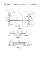
- FIG. 1is a schematic view of a typical prior art RF distribution system.
- FIG. 2is a diagram showing the typical RF bandwidth and a typical transmission bandwidth.
- FIG. 3is a diagram showing the transmission bandwidth and the bandwidth of the IF signal.
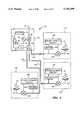
- FIG. 4is a schematic view of a simple RF distribution system according to the invention.
- FIG. 5Ais a diagram showing the stabilization of reference tones.
- FIG. 5Bis a diagram showing the relationship between the IF signal and the global reference tone.
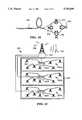
- FIG. 6is a schematic view of an RF distribution system according to the invention with multiple remote coverage sites.
- FIG. 7is a schematic view of another RF distribution system according to the invention.
- FIG. 8is a schematic view illustrating the overlap in coverage areas.
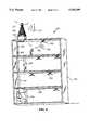
- FIG. 9is a three-dimensional view of the RF distribution system according to the invention adapted to a building structure.
- FIG. 10is a diagram showing typical 10 Base T in-building cables.
- FIG. 11is a schematic diagram of another RF distribution system according to the invention.
- FIG. 12is a schematic diagram of still another RF distribution system according to the invention.
- FIG. 13is a diagram illustrating a portion of a system of the invention using multi-mode optical fiber.
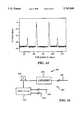
- FIG. 14is a graph of the Two Tone Test for the system of FIG. 13.
- FIG. 15is a diagram of an advantageous IF signal amplification method according to the invention.
- FIG. 1The salient features of the invention will be best appreciated after reviewing the typical prior art distribution system 10 for radio frequency (RF) signal 12 illustrated in FIG. 1.
- RF signal 12is in a bandwidth typically used for cellular communications or the like.
- FIG. 2indicates a RF bandwidth 30, spanning the range from 824 MHz to 894 MHz. This range is typical for RF signal 12 used in cellular communications.
- RF signal 12is received by main or base antenna 14.
- Connection 16e.g., a coaxial cable, delivers RF signal 12 from antenna 14 to one of the inputs of a first mixer 18.
- the second input of mixer 18is connected to a first local oscillator 20.
- Oscillator 20provides an RF frequency tone which is utilized by mixer 18 to down-convert RF signal 12 to an intermediate frequency (IF) and to feed it through a low bandwidth medium 33, such as a standard, pre-installed cable.
- IFintermediate frequency
- FIG. 2better illustrates the relationships of the various signals and their bandwidths.
- the down-conversion of RF signal 12 from RF bandwidth 30yields an IF signal 32 contained in a transmission bandwidth 34.
- Transmission bandwidth 34ranges from 0 to 100 MHz, which is typical for low bandwidth media commonly installed in building structures.
- IF signal 32is transmitted through medium 33 to a remote location or site 36 delineated by a broken line.
- Site 36is usually a room inside a building structure or some other area in which RF coverage is desired.
- IF signal 32is received by a second mixer 38, which, with the aid of oscillator 40, up-converts IF signal 32 to recover original RF signal 12.
- a remote antenna 42is used to re-transmit RF signal 12 in remote site 36.
- distribution system 10 and other related prior art systemssuffer from instability of local oscillators 20 and 40 (unless very expensive oscillators are used).
- An RF distribution system 50 according to the invention and shown in FIG. 4avoids this disadvantage in a simple and effective manner.
- system 50has a main or base antenna 52 which receives RF signal 12.
- Antenna 52is connected by a communication link 54, e.g., a coaxial cable or any other link capable of transmitting RF signal 12 without undue distortions, to one of the inputs of a first mixer 56.
- the type of device selected as mixer 56can include any suitable single ended, balanced, double-balanced, double-double balanced or other mixer.
- a first local oscillator 58preferably a voltage-controlled oscillator (VCO), is connected to another input of mixer 56.
- a low bandwidth medium 60such as 10 base T cable, telephone wire, fiber-optic cable, unshielded or shielded cable, power cable, or any other low bandwidth in-building medium is connected to the output of mixer 56.
- Oscillator 58is typically a low-cost device which by itself produces an unstable RF reference tone.
- One output of oscillator 58is connected to mixer 56 and another output leads to a frequency divider 62.
- the function of divider 62is fulfilled by any frequency dividing device or circuit capable of dividing the received tone by an integer.
- the output of divider 62is further connected to one input of a phase comparator 64. Suitable comparators are well-known in the art.
- the second input of comparator 64is connected to a global reference oscillator 66.
- oscillator 66is housed in a separate housing unit or distribution hub 68.
- hub 68is installed in an area not exposed to excessive temperature fluctuations, vibrations, or other external influences. These conditions are frequently met inside buildings away from windows, doors, or other openings, e.g., in basements.
- the preferred embodimentemploys as oscillator 66 a temperature-stabilized crystal oscillator. Devices of this kind can achieve stability figures of about 1 part per million and are commercially available. The frequency of oscillator 66 will be discussed below.
- any element of system 50 in need of the tone from oscillator 66can be supplied with it through lines 70.
- one of lines 70connects oscillator 66 to the other input of comparator 64.
- the output of comparator 64is connected to a filter 72.
- a suitable low-pass loop filteris well-known in the art and can be constructed from commercially available components.
- the output of filter 72is connected to the control input of oscillator 58.
- system 50has a summing element or adding device 74 connecting one of lines 70 to low bandwidth medium 60.
- Device 74can combine signals already traveling through medium 60 with any additional signal, in this case the signal produced by oscillator 66. Devices capable of performing this operation are well-known in the art.
- medium 60is connected to a filter 78 and to a second mixer 80.
- Filter 78has a pre-set band-pass for selecting a specific frequency from the signals transmitted through medium 60.
- the output of filter 78is connected to one of the inputs of a phase comparator 82.
- the other input of comparator 82is connected to the output of a frequency divider 84, analogous to frequency divider 62, which, is connected to a second local oscillator 86.
- local oscillator 86is a voltage-controlled oscillator which produces an unstable RF reference tone.
- the output of comparator 82is hooked up through a filter 88 to the controlling input of oscillator 86.
- oscillator 86, divider 84, comparator 82 and filter 88form a phase-locking device or circuit 90, frequently also called a phase-locked loop (PLL).
- oscillator 58, filter 72, comparator 64 and divider 62also form a phase-locking circuit 92. Both circuits, 90 and 92, are analogous in construction and operation, as will be shown below.
- Remote coverage site 76has a re-transmitting unit 95, in this case an RF antenna for re-transmitting RF signal 12 from mixer 80. Proper positioning of antenna 95 at site 76 to ensure RF coverage will be determined by the persons installing system 50 on a case by case basis.
- main antenna 52 of RF distribution system 50receives RF signal 12.
- RF signal 12is contained in RF bandwidth 30 ranging from 824 MHz to 894 MHz.
- RF bandwidth 30can be selected from the group of RF bandwidths used for cellular communications, cordless telephony, local RF communications, satellite television, interactive multi-media video, high bit-rate local area networks, and the like. The characteristic feature shared by all these RF bandwidths is that they are higher than transmission bandwidth 34 of medium 60.
- Antenna 52delivers RF signal 12 via communication link 54 to first mixer 56.
- phase-locked loop 92delivers a first RF reference tone 96 (see FIG. 2) of high stability to mixer 56.
- first mixer 56responds to these two inputs by generating an IF signal 94, or, in other words, down-converting RF signal 12.
- the result of the down-conversion--IF signal 94--is shown in FIG. 3.
- the actual bandwidth of down-converted RF signal 12, i.e., IF signal 94,can vary as conditioned by available in-building infrastructure. At any rate, since the output of first mixer 56 is connected to medium 60, IF signal 94 is transmitted or fed through medium 60.
- the down-conversion processitself depends on the stability of first RF reference tone 96 supplied to first mixer 56, and the former usually depends on the stability of first local oscillator 58. In this case, however, the output of oscillator 58 is a first RF reference tone 96 of high stability. This result is achieved in several steps with the aid of the remainder of phase-locking circuit 92 and global reference oscillator 66.
- the original output of oscillator 58which is an unstable RF reference tone 98 is fed to frequency divider 62.
- the inherent fluctuation of tone 98is evident from its wide spread of possible frequencies.
- Divider 62is set to divide tone 98 by an integer to derive an unstable IF reference tone 100, as shown. It is intended that unstable IF reference tone 100 match closely the frequency of a global reference tone 102 generated by global reference oscillator 66 residing in distribution hub 68. Also, unstable IF reference tone 100 as well as global reference tone 102 are contained within transmission bandwidth 34 of medium 60.
- global reference tone 102is in the middle of the bandwidth occupied by unstable IF reference tone 100. Furthermore, it is preferable that the bandwidth of IF reference tone 100, and consequently the frequency of global reference tone 102, lie outside the bandwidth of IF signal 94. This configuration avoids any potential interference between IF signal 94 and reference tone 100.
- the bandwidth of IF reference tone 100is below the bandwidth of IF signal 94 and centers around the frequency of global reference tone 102 equal to 8.0 MHz.
- Phase comparator 64receives at its two inputs unstable IF reference tone 100 and, through line 70, the highly stable global reference tone 102. In response to these two inputs comparator 64 generates at its output a first adjustment signal 104 representative of the phase mismatch or difference between unstable tone 100 and stable tone 102. Filter 72 clears adjustment signal 104 of high frequency noise, and ensures stability of the feedback loop. From filter 72 adjustment signal 104 passes to the control input of first local oscillator 58. There, adjustment signal 104 is used to fine-tune the oscillation frequency of oscillator 58.
- phase-locking circuit 92Thanks to the feedback nature of phase-locking circuit 92, the fine-tuning or trimming of oscillator 58 is performed continuously using the very stable global reference tone 102 as the benchmark. Consequently, the output of oscillator 58 is forced to generate first RF reference tone 96 of high stability.
- First mixer 56takes advantage of this high stability reference tone 96 to produce very accurately down-converted IF signal 94, which is then fed through medium 60.
- distribution hub 68is connected to summing element 74, which interfaces with medium 60.
- summing element 74which interfaces with medium 60.
- IF signal 94 already traveling through medium 60is combined with global reference tone 102 and sent through medium 60 to remote coverage site 76.
- No undesirable interferenceis created between IF signal 94 and tone 102 result, since their bandwidths do not overlap. In this manner, global reference tone 102 is efficiently forwarded to remote site 76 through the same medium as the useful signal.
- filter 78retrieves global reference tone 102 from medium 60. Meanwhile, IF signal 94 passes through to second mixer 80.
- Phase-locking circuit 90uses tone 102 to stabilize the output of second local oscillator 86.
- comparator 82produces a second adjustment signal 106 and delivers it through filter 88 to the control input of oscillator 86.
- the output of oscillator 86generates stable RF reference tone 96.
- Mixer 80uses stable RF reference tone 96 to up-convert IF signal 94 and recover RF signal 12 with minimal signal distortion. Then, RF antenna 95 receives RF signal 12 and re-transmits it throughout site 76.
- System 50is thus well-adapted to RF distribution in buildings and other structures using existing low bandwidth media such as conventional cables.
- the system resourcesare basic. Only one cost-intensive oscillator, namely global reference oscillator 66, is required to ensure proper up- and down-conversion of signals in this arrangement.
- the other essential elementsare simple, easy to install, and generally low-cost.
- voltage-controlled oscillatorssuch as oscillators 58 and 86 generating stable reference RF reference tone 96 at 800 MHz using 3.125 MHz as global reference tone 102 can achieve high stability at a very low cost.
- FIG. 6A more practical RF distribution system 110 according to the invention is illustrated in FIG. 6. Corresponding parts of this embodiment are designated with the same reference numbers as in the first embodiment.
- Communication link 54delivers RF signal 12 to a main hub 112.
- first mixer 56Housed inside main hub 112 is first mixer 56 and first local oscillator 58.
- Divider 62, comparator 64 and filter 72are connected and operate in the same manner as described above and are also housed in hub 112.
- global reference oscillator 66 and summing element 74are inside hub 112 as well. In this manner, all elements necessary to convert RF signal 12 to IF signal 94 are arranged in the same compact unit.
- Summing element 74is connected to three low bandwidth cables 114, which are routed to their respective remote coverage sites 116, 118, 120.
- Phased-locking circuits 122, 124, 126 and filters 128, 130, and 132are connected in the same manner and perform the same functions as filter 78 and circuit 90 in the previous embodiment.
- circuits 122, 124, 126 and filters 128, 130, and 132allow each remote site 116, 118, 120 to filter out global reference signal 102 and use it to produce a stable second RF reference signal 96.
- each remote site 116, 118, 120has its own second mixer 134, 136, and 138 for recovering RF signal 12 from IF signal 94. After recovery RF signal 12 is re-transmitted at each remote site 116, 118, 120 by a corresponding RF antenna 140, 142, 144.
- Distribution system 110is more compact and practical in some applications by virtue of using one single hub 112.
- hub 112have to ensure that the internal elements are protected.
- global reference oscillator 66has to be isolated in a manner to ensure stability of global reference tone 102.
- FIG. 7illustrates another RF distribution system 150 according to the invention.
- RF signal 12received by main antenna 52, is delivered to first mixer 56 to be down-converted to produce IF signal 94.
- Global reference oscillatoris housed separately in a distribution hub 152. From there global reference tone 102 is distributed through links 154 to network hubs 156 and 158, and to phase-locking loop 92.
- Network hubs 156 and 158contain multiple summing elements 74 which allow one to launch global reference tone 102 on many low bandwidth cables 160.
- cables 160constitute a network 162.
- Cables 160A-Dwhen viewed independently, form a tree network, while all cables 160 form two star networks with hubs 156 and 158 representing their centers.
- distribution system 150 of the inventioncan be adapted to any existing network of in-building cables.
- any star network, tree network, ring network or branch networkis suited for distributing RF signal 12 according to the invention.
- links 154do not need to be part of the network infrastructure if other media for distributing global reference signal 102 are deemed convenient by the system designer.
- global reference tone 102can be distributed through fiber-optic links, or AC power lines.
- FIG. 8shows a particularly advantageous aspect of the invention.
- Two remote coverage sites 170 and 172have corresponding RF antennas 174 and 176 for re-transmitting RF signal 12.
- IF signal 94is fed through a low bandwidth medium, in this case power cables 178 and 180.
- Units 182 and 184contain all the elements discussed above necessary for recovering RF signal 12 from IF signal 94 according to the invention.
- the region where this happensis hatched and designated by reference numeral 186.
- overlap in coverage of adjacent sitesis desirable because it guarantees complete coverage.
- a user equipped with an RF receiver (not shown) and positioned in region 186will intercept RF signal 12 from both antennas 174 and 176.
- ⁇ ffrequency difference between RF signal 12 coming from antenna 174 and the same RF signal 12 arriving from antenna 176.
- This frequency differencetypically about ⁇ 500 Hz
- the beat frequencycan impair the functioning of the electrical components and introduce spurious signals.
- RF distribution systems used for data transfercan experience higher bit error rates (BER) and other degrading effects.
- RF distribution systemscan recover RF signal 12 with no frequency shift at all.
- RF signal 12 radiated from antenna 174 and from antenna 176will have the same frequency and not induce any beats.
- FIG. 9illustrates an RF distribution system 190 according to the invention used in a building structure 192.
- system 190is bi-directional, i.e., RF antennas 194 installed in various locations throughout structure 192 can re-transmit and receive RF signals 12.
- transmitted RF signalsare designated by 12A and received RF signals are indicated by 12B.
- a main antenna 196 mounted on the roof of structure 192can also transmit and receive RF signals 12A and 12B.
- System 190utilizes in-building low bandwidth network including cables 198, 200, 202, 204, and wiring closets 206 and 208 to distribute RF signal 12.
- wiring closet 208houses a distribution hub 210.
- the lattersupplies global reference tone 102 from a temperature-stabilized crystal oscillator serving as the global reference oscillator (not shown). Protection of hub 210 from external influences is ensured by virtue of location of closet 208 on the ground floor and away from openings such as doors or windows.
- cables 198, 200, 202, 204may constitute a pre-existing network which can not be extensively modified by the designer without expensive re-routing work.
- cables 198, 200, 202, 204are standard AC power cables which are truly ubiquitous even in old structures. The choice of AC power cables will allow one to distribute RF signals in virtually any environment without altering the in-building cabling, thus providing an ultra-low-cost RF distribution network.
- An additional advantage of using AC power linesis that the power for operating antennas 194 and any other necessary electronics (not shown) can be provided through cables 198, 200, 202, and 204 simultaneously with the IF signal.
- AC power linesare pre-installed, the designer of the RF distribution system will encounter some limitations. Indeed, in some rooms the locations of antennas 194 may be imposed by the infrastructure.
- system 190is assumed to be used for cordless telephony.
- Cordless telephonesoperate in the 900 MHz frequency band and has a narrow bandwidth which can be transmitted through cables 198, 200, 202, 204.
- antennas 194should be placed in locations outside building 192 as well (e.g., near a swimming pool, etc.).
- FIG. 10illustrates the most common low bandwidth medium 220 found inside buildings.
- medium 220is a cable consisting of four twisted pairs 222, 224, 226, 228 or wire pairs. These can all be used for distributing signals for cellular communications, cordless telephony, local RF communications, satellite television, interactive multi-media video, or high bit-rate local area networks.
- FIG. 11illustrates schematically yet another RF distribution system 230 according to the invention.
- Main antenna 232is positioned on top of a building 234 to receive and transmit RF signals 12A and 12B.
- System 230consists of three star networks 238A, 238B, 238C, one per floor, individually fed from antenna 232.
- Networks 238A, 238B, 238Chave RF antennas 240 and independent hubs 242A, 242B, 242C for housing the essential components discussed above.
- FIG. 12illustrates another advantageous RF distribution system 250 inside same building 252.
- System 250takes advantage of a pre-installed private branch exchange 254 (PBX) and does away with a main antenna as the unit for receiving and re-transmitting RF signals 12A and 12B.
- PBXprivate branch exchange 254
- RF signals 12A and 12Bare delivered to PBX 254 and received from it by any suitable high bandwidth medium (not shown).
- RF signals 12Bare fed by PBX 254 to hubs 258A, 258B, 258C of three star networks 256A, 256B, 256C.
- RF signals 12Aare received from star networks 256A, 256B, 256C and sent back to PBX 254, which re-transmits them via the high bandwidth medium.
- PBX systemsare widespread, this embodiment is very practical. No additional cables need to be routed from any external RF antennas in this case.
- PBX systemsare found in many locations and are frequently pre-wired for indoor within one or more building structures, and, in some cases, outdoor operation as well. Few modifications will be required to install an RF distribution system according to the invention in this manner.
- FIG. 13illustrates a portion of yet another system 260 according to the invention.
- a low bandwidth medium 262in this case a multi-mode fiber optic cable, connects a LED (Light Emitting Diode) unit 264 to a low-speed analog detector 266 at a remote site 270. Because the transmission bandwidth of optic cable 262 required for this invention is below 100 MHz the length of cable 262 can exceed 1 km. The ability to cover such distances renders the embodiment particularly useful in shopping centers and other structures covering large areas.
- Same mixer 56 as in FIG. 4delivers IF signal 94 to LED unit 264 via low bandwidth medium 268.
- Medium 268may belong to a pre-installed network, e.g., AC power mains or telephone wires.
- LED unit 264exhibit an excellent response at low frequencies, in particular within the transmission bandwidth of medium 262, ( ⁇ 100 MHz), and no response at higher frequencies, e.g., 1 GHz.
- LED unit 264is well-suited for feeding IF signal 94 through medium 262.
- Conventional optical systemsuse lasers and single-mode optical fibers, both of which are expensive, to send signals at various frequencies. This embodiment is very low cost in comparison with conventional systems and very efficient in the desired frequency range.
- FIG. 14shows the results of a standard Two Tone Test for LED unit 264 operating at 1.3 um and 1 km long cable 262.
- FIG. 15shows an advantageous addition to a portion of a system 280 according to the invention.
- System 280uses a summing element 288 for adding global reference tone 102 to IF signal 94, as discussed above, and feeding both through a network 290 consisting of low bandwidth cables 286.
- Two standard amplifiers 282 and 284 for amplifying signals within transmission bandwidth 34are connected to cables 286.
- amplifiers 282 and 284amplify IF signal 94 while it passes through cables 286. If desired, both or one of amplifiers 282, 284 can also amplify global reference tone 102.
- amplifying signals at lower frequenciesis simpler and less costly than amplifying RF frequency signals.
- This "repeater function"can be incorporated in any of the above embodiments by installing suitable low frequency amplifiers ( ⁇ 100 MHz) at frequencies corresponding to the IF signals and/or to the global reference tone.
- the presented embodimentsare only illustrative of some of the many types of networks which can be used according to the invention to distribute RF signals. Every particular network will be different, as conditioned by pre-existing infrastructure. Adaptations to particular bandwidths and frequencies, (e.g., for IF signals) will be made depending on application.
Landscapes
- Engineering & Computer Science (AREA)
- Computer Networks & Wireless Communication (AREA)
- Signal Processing (AREA)
- Power Engineering (AREA)
- Radio Relay Systems (AREA)
- Mobile Radio Communication Systems (AREA)
- Transmitters (AREA)
- Two-Way Televisions, Distribution Of Moving Picture Or The Like (AREA)
Abstract
Description
Claims (30)
Priority Applications (1)
| Application Number | Priority Date | Filing Date | Title |
|---|---|---|---|
| US08/871,556US5765099A (en) | 1996-04-19 | 1997-06-10 | Distribution of radio-frequency signals through low bandwidth infrastructures |
Applications Claiming Priority (2)
| Application Number | Priority Date | Filing Date | Title |
|---|---|---|---|
| US63536896A | 1996-04-19 | 1996-04-19 | |
| US08/871,556US5765099A (en) | 1996-04-19 | 1997-06-10 | Distribution of radio-frequency signals through low bandwidth infrastructures |
Related Parent Applications (1)
| Application Number | Title | Priority Date | Filing Date |
|---|---|---|---|
| US63536896AContinuation | 1996-04-19 | 1996-04-19 |
Publications (1)
| Publication Number | Publication Date |
|---|---|
| US5765099Atrue US5765099A (en) | 1998-06-09 |
Family
ID=24547515
Family Applications (1)
| Application Number | Title | Priority Date | Filing Date |
|---|---|---|---|
| US08/871,556Expired - LifetimeUS5765099A (en) | 1996-04-19 | 1997-06-10 | Distribution of radio-frequency signals through low bandwidth infrastructures |
Country Status (12)
| Country | Link |
|---|---|
| US (1) | US5765099A (en) |
| EP (1) | EP0894369B1 (en) |
| JP (1) | JP3565563B2 (en) |
| CN (1) | CN1240192C (en) |
| AT (1) | ATE260001T1 (en) |
| AU (1) | AU715343B2 (en) |
| CA (1) | CA2251959C (en) |
| DE (1) | DE69727664T2 (en) |
| DK (1) | DK0894369T3 (en) |
| ES (1) | ES2216144T3 (en) |
| PT (1) | PT894369E (en) |
| WO (1) | WO1997040590A1 (en) |
Cited By (117)
| Publication number | Priority date | Publication date | Assignee | Title |
|---|---|---|---|---|
| WO2000033585A3 (en)* | 1998-12-01 | 2000-09-08 | Phonex Corp | Method and system for combining wireless phone jack and rf wireless communications |
| US6151480A (en)* | 1997-06-27 | 2000-11-21 | Adc Telecommunications, Inc. | System and method for distributing RF signals over power lines within a substantially closed environment |
| US6157810A (en)* | 1996-04-19 | 2000-12-05 | Lgc Wireless, Inc | Distribution of radio-frequency signals through low bandwidth infrastructures |
| WO2001033743A1 (en)* | 1999-11-01 | 2001-05-10 | Qualcomm Incorporated | Split repeater |
| WO2001033878A3 (en)* | 1999-10-29 | 2001-11-01 | Qualcomm Inc | In-building radio-frequency coverage |
| EP1091508A4 (en)* | 1998-06-24 | 2002-01-23 | Sk Telecom Co Ltd | REPEAT DEVICE WITH TELEPHONE CONNECTION |
| WO2002009319A1 (en)* | 2000-07-19 | 2002-01-31 | Adc Telecommunications, Inc. | A method for point-to-multipoint communication using digital radio frequency transport |
| US20020093926A1 (en)* | 2000-12-05 | 2002-07-18 | Kilfoyle Daniel B. | Method and system for a remote downlink transmitter for increasing the capacity of a multiple access interference limited spread-spectrum wireless network |
| US6580918B1 (en)* | 1997-08-05 | 2003-06-17 | Nokia Mobile Phones Ltd. | Cellular telecommunications system |
| US6615407B1 (en)* | 1999-02-19 | 2003-09-02 | Masprodenkoh Kabushikikaisha | In-building CATV system, and up-converter and down-converter for use therein |
| US20030214919A1 (en)* | 2001-09-17 | 2003-11-20 | Kilfoyle Daniel B. | Method and system for a channel selective repeater with capacity enhancement in a spread-spectrum wireless network |
| US20040106387A1 (en)* | 2002-12-03 | 2004-06-03 | Adc Telecommunications, Inc. | Small signal threshold and proportional gain distributed digital communications |
| US20040106435A1 (en)* | 2002-12-03 | 2004-06-03 | Adc Telecommunications, Inc. | Distributed digital antenna system |
| US20040203339A1 (en)* | 2002-12-03 | 2004-10-14 | Bauman Donald R. | Distributed signal summation and gain control |
| US20050018630A1 (en)* | 1999-04-21 | 2005-01-27 | Opencell Corp. | Architecture for signal distribution in wireless data network |
| US20050088999A1 (en)* | 2002-01-31 | 2005-04-28 | Waylett Nicholas S. | Communication system having a community wireless local area network for voice and high speed data communication |
| US20050114903A1 (en)* | 2000-02-08 | 2005-05-26 | Sherjil Ahmed | Method and apparatus for a digitized CATV network for bundled services |
| US6967966B1 (en) | 1999-11-03 | 2005-11-22 | Adc Telecommunications, Inc. | Digital return path for hybrid fiber/coax network |
| US7016308B1 (en) | 1999-03-19 | 2006-03-21 | Broadband Royalty Corporation | Digital return path for hybrid fiber/coax network |
| US7031335B1 (en) | 1999-11-03 | 2006-04-18 | Adc Telecommunications, Inc. | Digital node for hybrid fiber/coax network |
| US7047555B1 (en)* | 1999-07-23 | 2006-05-16 | Masprodenkoh Kabushikikaisha | In-building CATV system, down-converter, up-converter and amplifier |
| US7061891B1 (en) | 2001-02-02 | 2006-06-13 | Science Applications International Corporation | Method and system for a remote downlink transmitter for increasing the capacity and downlink capability of a multiple access interference limited spread-spectrum wireless network |
| US20070008939A1 (en)* | 2005-06-10 | 2007-01-11 | Adc Telecommunications, Inc. | Providing wireless coverage into substantially closed environments |
| US20070070744A1 (en)* | 2005-09-27 | 2007-03-29 | Macronix International Co., Ltd. | Fast pre-charge circuit and method of providing same for memory devices |
| US20070264009A1 (en)* | 2006-04-28 | 2007-11-15 | Adc Telecommunications, Inc. | Systems and methods of optical path protection for distributed antenna systems |
| US20080014948A1 (en)* | 2006-07-14 | 2008-01-17 | Lgc Wireless, Inc. | System for and method of for providing dedicated capacity in a cellular network |
| US20080058018A1 (en)* | 2006-08-29 | 2008-03-06 | Lgc Wireless, Inc. | Distributed antenna communications system and methods of implementing thereof |
| US20080151846A1 (en)* | 2006-12-22 | 2008-06-26 | Stefan Scheinert | System for and method of providing remote coverage area for wireless communications |
| US20080181171A1 (en)* | 2007-01-25 | 2008-07-31 | Adc Telecommunications, Inc. | Distributed remote base station system |
| US20080181282A1 (en)* | 2007-01-25 | 2008-07-31 | Adc Telecommunications, Inc. | Modular wireless communications platform |
| US20080232305A1 (en)* | 2006-12-19 | 2008-09-25 | Yair Oren | Distributed Antenna System for MIMO Technologies |
| US20080232328A1 (en)* | 2007-03-23 | 2008-09-25 | Stefan Scheinert | Localization of a mobile device in distributed antenna communications system |
| US20090005096A1 (en)* | 2007-06-26 | 2009-01-01 | Stefan Scheinert | Distributed antenna communications system |
| US20090061940A1 (en)* | 2007-08-31 | 2009-03-05 | Stefan Scheinert | System for and method of configuring distributed antenna communications system |
| US20090176448A1 (en)* | 2002-02-25 | 2009-07-09 | Adc Telecommunications, Inc. | Distributed automatic gain control system |
| US20090247076A1 (en)* | 2006-07-21 | 2009-10-01 | Allan Bartlett | Radio frequency signal distribution using data cable system |
| US7599711B2 (en) | 2006-04-12 | 2009-10-06 | Adc Telecommunications, Inc. | Systems and methods for analog transport of RF voice/data communications |
| US7630344B1 (en) | 2001-03-30 | 2009-12-08 | Science Applications International Corporation | Multistage reception of code division multiple access transmissions |
| US20090316609A1 (en)* | 2008-06-24 | 2009-12-24 | Lgc Wireless, Inc. | System and method for synchronized time-division duplex signal switching |
| US20090323767A1 (en)* | 2006-07-21 | 2009-12-31 | Allan Bartlett | Radio frequency distribution with spreading |
| US20100309931A1 (en)* | 2007-10-22 | 2010-12-09 | Mobileaccess Networks Ltd. | Communication system using low bandwidth wires |
| US20110216751A1 (en)* | 1999-04-21 | 2011-09-08 | Lgc Wireless, Inc. | Architecture for signal and power distribution in wireless data network |
| US20110237182A1 (en)* | 2010-03-25 | 2011-09-29 | Adc Telecommunications, Inc. | Automatic gain control configuration for a wideband distributed antenna system |
| US8175649B2 (en) | 2008-06-20 | 2012-05-08 | Corning Mobileaccess Ltd | Method and system for real time control of an active antenna over a distributed antenna system |
| US8184681B2 (en) | 2006-01-11 | 2012-05-22 | Corning Mobileaccess Ltd | Apparatus and method for frequency shifting of a wireless signal and systems using frequency shifting |
| US8325759B2 (en) | 2004-05-06 | 2012-12-04 | Corning Mobileaccess Ltd | System and method for carrying a wireless based signal over wiring |
| US8462683B2 (en) | 2011-01-12 | 2013-06-11 | Adc Telecommunications, Inc. | Distinct transport path for MIMO transmissions in distributed antenna systems |
| US8472579B2 (en) | 2010-07-28 | 2013-06-25 | Adc Telecommunications, Inc. | Distributed digital reference clock |
| US8532492B2 (en) | 2009-02-03 | 2013-09-10 | Corning Cable Systems Llc | Optical fiber-based distributed antenna systems, components, and related methods for calibration thereof |
| US8532242B2 (en) | 2010-10-27 | 2013-09-10 | Adc Telecommunications, Inc. | Distributed antenna system with combination of both all digital transport and hybrid digital/analog transport |
| US8639121B2 (en) | 2009-11-13 | 2014-01-28 | Corning Cable Systems Llc | Radio-over-fiber (RoF) system for protocol-independent wired and/or wireless communication |
| US8644844B2 (en) | 2007-12-20 | 2014-02-04 | Corning Mobileaccess Ltd. | Extending outdoor location based services and applications into enclosed areas |
| US8693342B2 (en) | 2011-10-28 | 2014-04-08 | Adc Telecommunications, Inc. | Distributed antenna system using time division duplexing scheme |
| US8718478B2 (en) | 2007-10-12 | 2014-05-06 | Corning Cable Systems Llc | Hybrid wireless/wired RoF transponder and hybrid RoF communication system using same |
| US8831428B2 (en) | 2010-02-15 | 2014-09-09 | Corning Optical Communications LLC | Dynamic cell bonding (DCB) for radio-over-fiber (RoF)-based networks and communication systems and related methods |
| US8867919B2 (en) | 2007-07-24 | 2014-10-21 | Corning Cable Systems Llc | Multi-port accumulator for radio-over-fiber (RoF) wireless picocellular systems |
| US8897215B2 (en) | 2009-02-08 | 2014-11-25 | Corning Optical Communications Wireless Ltd | Communication system using cables carrying ethernet signals |
| US8983301B2 (en) | 2010-03-31 | 2015-03-17 | Corning Optical Communications LLC | Localization services in optical fiber-based distributed communications components and systems, and related methods |
| US9001811B2 (en) | 2009-05-19 | 2015-04-07 | Adc Telecommunications, Inc. | Method of inserting CDMA beacon pilots in output of distributed remote antenna nodes |
| US9158864B2 (en) | 2012-12-21 | 2015-10-13 | Corning Optical Communications Wireless Ltd | Systems, methods, and devices for documenting a location of installed equipment |
| US9178635B2 (en) | 2014-01-03 | 2015-11-03 | Corning Optical Communications Wireless Ltd | Separation of communication signal sub-bands in distributed antenna systems (DASs) to reduce interference |
| US9178636B2 (en) | 2013-02-22 | 2015-11-03 | Adc Telecommunications, Inc. | Universal remote radio head |
| US9184960B1 (en) | 2014-09-25 | 2015-11-10 | Corning Optical Communications Wireless Ltd | Frequency shifting a communications signal(s) in a multi-frequency distributed antenna system (DAS) to avoid or reduce frequency interference |
| US9184843B2 (en) | 2011-04-29 | 2015-11-10 | Corning Optical Communications LLC | Determining propagation delay of communications in distributed antenna systems, and related components, systems, and methods |
| US9185674B2 (en) | 2010-08-09 | 2015-11-10 | Corning Cable Systems Llc | Apparatuses, systems, and methods for determining location of a mobile device(s) in a distributed antenna system(s) |
| US9240835B2 (en) | 2011-04-29 | 2016-01-19 | Corning Optical Communications LLC | Systems, methods, and devices for increasing radio frequency (RF) power in distributed antenna systems |
| US9247543B2 (en) | 2013-07-23 | 2016-01-26 | Corning Optical Communications Wireless Ltd | Monitoring non-supported wireless spectrum within coverage areas of distributed antenna systems (DASs) |
| US9258052B2 (en) | 2012-03-30 | 2016-02-09 | Corning Optical Communications LLC | Reducing location-dependent interference in distributed antenna systems operating in multiple-input, multiple-output (MIMO) configuration, and related components, systems, and methods |
| US9338823B2 (en) | 2012-03-23 | 2016-05-10 | Corning Optical Communications Wireless Ltd | Radio-frequency integrated circuit (RFIC) chip(s) for providing distributed antenna system functionalities, and related components, systems, and methods |
| US9357551B2 (en) | 2014-05-30 | 2016-05-31 | Corning Optical Communications Wireless Ltd | Systems and methods for simultaneous sampling of serial digital data streams from multiple analog-to-digital converters (ADCS), including in distributed antenna systems |
| US9385810B2 (en) | 2013-09-30 | 2016-07-05 | Corning Optical Communications Wireless Ltd | Connection mapping in distributed communication systems |
| US9420542B2 (en) | 2014-09-25 | 2016-08-16 | Corning Optical Communications Wireless Ltd | System-wide uplink band gain control in a distributed antenna system (DAS), based on per band gain control of remote uplink paths in remote units |
| US9419712B2 (en) | 2010-10-13 | 2016-08-16 | Ccs Technology, Inc. | Power management for remote antenna units in distributed antenna systems |
| US9455784B2 (en) | 2012-10-31 | 2016-09-27 | Corning Optical Communications Wireless Ltd | Deployable wireless infrastructures and methods of deploying wireless infrastructures |
| US9497706B2 (en) | 2013-02-20 | 2016-11-15 | Corning Optical Communications Wireless Ltd | Power management in distributed antenna systems (DASs), and related components, systems, and methods |
| US9509133B2 (en) | 2014-06-27 | 2016-11-29 | Corning Optical Communications Wireless Ltd | Protection of distributed antenna systems |
| US9525472B2 (en) | 2014-07-30 | 2016-12-20 | Corning Incorporated | Reducing location-dependent destructive interference in distributed antenna systems (DASS) operating in multiple-input, multiple-output (MIMO) configuration, and related components, systems, and methods |
| US9531452B2 (en) | 2012-11-29 | 2016-12-27 | Corning Optical Communications LLC | Hybrid intra-cell / inter-cell remote unit antenna bonding in multiple-input, multiple-output (MIMO) distributed antenna systems (DASs) |
| US9554194B2 (en) | 2013-06-20 | 2017-01-24 | Antronix Inc. | System and method for providing data communication services through a CATV tap-off device |
| US9577922B2 (en) | 2014-02-18 | 2017-02-21 | Commscope Technologies Llc | Selectively combining uplink signals in distributed antenna systems |
| US9590733B2 (en) | 2009-07-24 | 2017-03-07 | Corning Optical Communications LLC | Location tracking using fiber optic array cables and related systems and methods |
| US9596322B2 (en) | 2014-06-11 | 2017-03-14 | Commscope Technologies Llc | Bitrate efficient transport through distributed antenna systems |
| US9602210B2 (en) | 2014-09-24 | 2017-03-21 | Corning Optical Communications Wireless Ltd | Flexible head-end chassis supporting automatic identification and interconnection of radio interface modules and optical interface modules in an optical fiber-based distributed antenna system (DAS) |
| US9621293B2 (en) | 2012-08-07 | 2017-04-11 | Corning Optical Communications Wireless Ltd | Distribution of time-division multiplexed (TDM) management services in a distributed antenna system, and related components, systems, and methods |
| US9648580B1 (en) | 2016-03-23 | 2017-05-09 | Corning Optical Communications Wireless Ltd | Identifying remote units in a wireless distribution system (WDS) based on assigned unique temporal delay patterns |
| US9647758B2 (en) | 2012-11-30 | 2017-05-09 | Corning Optical Communications Wireless Ltd | Cabling connectivity monitoring and verification |
| US9653861B2 (en) | 2014-09-17 | 2017-05-16 | Corning Optical Communications Wireless Ltd | Interconnection of hardware components |
| US9661781B2 (en) | 2013-07-31 | 2017-05-23 | Corning Optical Communications Wireless Ltd | Remote units for distributed communication systems and related installation methods and apparatuses |
| US9673904B2 (en) | 2009-02-03 | 2017-06-06 | Corning Optical Communications LLC | Optical fiber-based distributed antenna systems, components, and related methods for calibration thereof |
| US9681313B2 (en) | 2015-04-15 | 2017-06-13 | Corning Optical Communications Wireless Ltd | Optimizing remote antenna unit performance using an alternative data channel |
| US9685782B2 (en) | 2010-11-24 | 2017-06-20 | Corning Optical Communications LLC | Power distribution module(s) capable of hot connection and/or disconnection for distributed antenna systems, and related power units, components, and methods |
| US9699723B2 (en) | 2010-10-13 | 2017-07-04 | Ccs Technology, Inc. | Local power management for remote antenna units in distributed antenna systems |
| US9715157B2 (en) | 2013-06-12 | 2017-07-25 | Corning Optical Communications Wireless Ltd | Voltage controlled optical directional coupler |
| US9729267B2 (en) | 2014-12-11 | 2017-08-08 | Corning Optical Communications Wireless Ltd | Multiplexing two separate optical links with the same wavelength using asymmetric combining and splitting |
| US9729251B2 (en) | 2012-07-31 | 2017-08-08 | Corning Optical Communications LLC | Cooling system control in distributed antenna systems |
| US9730228B2 (en) | 2014-08-29 | 2017-08-08 | Corning Optical Communications Wireless Ltd | Individualized gain control of remote uplink band paths in a remote unit in a distributed antenna system (DAS), based on combined uplink power level in the remote unit |
| US9775123B2 (en) | 2014-03-28 | 2017-09-26 | Corning Optical Communications Wireless Ltd. | Individualized gain control of uplink paths in remote units in a distributed antenna system (DAS) based on individual remote unit contribution to combined uplink power |
| US9781553B2 (en) | 2012-04-24 | 2017-10-03 | Corning Optical Communications LLC | Location based services in a distributed communication system, and related components and methods |
| US9785175B2 (en) | 2015-03-27 | 2017-10-10 | Corning Optical Communications Wireless, Ltd. | Combining power from electrically isolated power paths for powering remote units in a distributed antenna system(s) (DASs) |
| US9787457B2 (en) | 2013-10-07 | 2017-10-10 | Commscope Technologies Llc | Systems and methods for integrating asynchronous signals in distributed antenna system with direct digital interface to base station |
| US9807700B2 (en) | 2015-02-19 | 2017-10-31 | Corning Optical Communications Wireless Ltd | Offsetting unwanted downlink interference signals in an uplink path in a distributed antenna system (DAS) |
| US9948349B2 (en) | 2015-07-17 | 2018-04-17 | Corning Optical Communications Wireless Ltd | IOT automation and data collection system |
| US9974074B2 (en) | 2013-06-12 | 2018-05-15 | Corning Optical Communications Wireless Ltd | Time-division duplexing (TDD) in distributed communications systems, including distributed antenna systems (DASs) |
| US10020850B2 (en) | 2013-02-22 | 2018-07-10 | Commscope Technologies Llc | Master reference for base station network interface sourced from distributed antenna system |
| US10128951B2 (en) | 2009-02-03 | 2018-11-13 | Corning Optical Communications LLC | Optical fiber-based distributed antenna systems, components, and related methods for monitoring and configuring thereof |
| US10136200B2 (en) | 2012-04-25 | 2018-11-20 | Corning Optical Communications LLC | Distributed antenna system architectures |
| US10236924B2 (en) | 2016-03-31 | 2019-03-19 | Corning Optical Communications Wireless Ltd | Reducing out-of-channel noise in a wireless distribution system (WDS) |
| US10257056B2 (en) | 2012-11-28 | 2019-04-09 | Corning Optical Communications LLC | Power management for distributed communication systems, and related components, systems, and methods |
| US10455497B2 (en) | 2013-11-26 | 2019-10-22 | Corning Optical Communications LLC | Selective activation of communications services on power-up of a remote unit(s) in a wireless communication system (WCS) based on power consumption |
| US10499269B2 (en) | 2015-11-12 | 2019-12-03 | Commscope Technologies Llc | Systems and methods for assigning controlled nodes to channel interfaces of a controller |
| US10560214B2 (en) | 2015-09-28 | 2020-02-11 | Corning Optical Communications LLC | Downlink and uplink communication path switching in a time-division duplex (TDD) distributed antenna system (DAS) |
| WO2020123012A1 (en)* | 2018-12-10 | 2020-06-18 | Intel Corporation | Distributed relay |
| US10735822B2 (en) | 2013-06-20 | 2020-08-04 | Antronix Inc. | System and method for providing data communication services through a CATV tap-off device |
| US10785827B2 (en) | 2009-11-12 | 2020-09-22 | Andrew Wireless Systems Gmbh | Master unit, remote unit and multiband transmission system |
| US10992484B2 (en) | 2013-08-28 | 2021-04-27 | Corning Optical Communications LLC | Power management for distributed communication systems, and related components, systems, and methods |
| US11296504B2 (en) | 2010-11-24 | 2022-04-05 | Corning Optical Communications LLC | Power distribution module(s) capable of hot connection and/or disconnection for wireless communication systems, and related power units, components, and methods |
| US20240248210A1 (en)* | 2023-01-18 | 2024-07-25 | Agalti Corporation | Two-way frequency exchange between independently moving oscillators |
Families Citing this family (9)
| Publication number | Priority date | Publication date | Assignee | Title |
|---|---|---|---|---|
| JP4500401B2 (en)* | 2000-02-16 | 2010-07-14 | マスプロ電工株式会社 | Gap filler device for satellite broadcasting system and satellite broadcasting system |
| JP4663087B2 (en)* | 2000-09-21 | 2011-03-30 | マスプロ電工株式会社 | Gap filler for digital terrestrial broadcasting |
| US6844787B2 (en)* | 2002-09-13 | 2005-01-18 | Stratex Networks, Inc. | Method and apparatus for re-modulation using zero IF |
| JP4674184B2 (en)* | 2006-06-12 | 2011-04-20 | Dxアンテナ株式会社 | GPS signal transmission system |
| CN101242282B (en)* | 2008-02-14 | 2012-01-04 | 中国科学院计算技术研究所 | An user access device and wireless LAN system including this device |
| IT1398534B1 (en) | 2010-02-25 | 2013-03-01 | Wisytech S R L | EQUIPMENT FOR FEMTOCELLE TELECOMMUNICATION SYSTEM. |
| WO2014005637A1 (en) | 2012-07-05 | 2014-01-09 | Telefonaktiebolaget Lm Ericsson (Publ) | Methods and network nodes for communication between a first network node and a second network node over a twisted pair wire |
| JP6515747B2 (en)* | 2015-08-31 | 2019-05-22 | アイコム株式会社 | Communication system, frequency control method, remote terminal and program |
| JP7502926B2 (en) | 2020-08-11 | 2024-06-19 | 日本放送協会 | Level Adjustment Device |
Citations (17)
| Publication number | Priority date | Publication date | Assignee | Title |
|---|---|---|---|---|
| US2671850A (en)* | 1951-02-07 | 1954-03-09 | Pierre C Marcou | Radio relaying system |
| US2747083A (en)* | 1950-06-07 | 1956-05-22 | Radio Patents Company | Frequency-modulated high-frequency system |
| US4063173A (en)* | 1976-04-01 | 1977-12-13 | Motorola, Inc. | Dual mode receiver |
| US4186347A (en)* | 1978-10-31 | 1980-01-29 | Nasa | Radio frequency arraying method for receivers |
| US4417279A (en)* | 1981-02-16 | 1983-11-22 | Hitachi, Ltd. | FM Television signal receiving circuit |
| US4449246A (en)* | 1980-05-02 | 1984-05-15 | Harris Corporation | Orderwire communication system |
| US4476574A (en)* | 1980-09-17 | 1984-10-09 | The United States Of America As Represented By The United States Department Of Energy | Radio frequency communication system utilizing radiating transmission lines |
| US4500976A (en)* | 1982-06-07 | 1985-02-19 | Phillips Petroleum Company | Seismic exploration |
| US4556988A (en)* | 1982-09-27 | 1985-12-03 | Alps. Electric Co., Ltd. | Indoor unit of receiver for broadcasting satellite |
| US4856085A (en)* | 1986-03-21 | 1989-08-08 | U.S. Philips Corporation | FM receiver with improved adjacent-channel rejection |
| US4901368A (en)* | 1987-10-19 | 1990-02-13 | American Telephone And Telegraph Company | Frequency translation correction scheme for satellite communication system |
| US4959862A (en)* | 1988-04-28 | 1990-09-25 | Catel Telecommunications, Inc. | Active multichannel video processing hub for optimum transition from fiber to coax |
| US5046135A (en)* | 1989-11-30 | 1991-09-03 | John E. Chance & Associates | Method and apparatus for frequency stabilization of a down converter |
| US5109532A (en)* | 1990-01-30 | 1992-04-28 | General Instrument Corporation | Elimination of phase noise and drift incident to up and down conversion in a broadcast communication system |
| WO1994013067A1 (en)* | 1992-11-23 | 1994-06-09 | Telefonaktiebolaget Lm Ericsson | Radio coverage in closed environments |
| US5361407A (en)* | 1991-12-02 | 1994-11-01 | Sony Corporation | Double superheterodyne receiver with independent frequency calibration of two local oscillators |
| US5428836A (en)* | 1992-01-21 | 1995-06-27 | Motorola Inc. | Radio receiver for forming a baseband signal of time-varying frequencies |
Family Cites Families (3)
| Publication number | Priority date | Publication date | Assignee | Title |
|---|---|---|---|---|
| DK158688A (en)* | 1987-03-24 | 1988-09-25 | Mitsubishi Electric Corp | HIGH FREQUENCY SIGNAL AMPLIFIER |
| US5187803A (en)* | 1990-01-18 | 1993-02-16 | Andrew Corporation | Regenerative rf bi-directional amplifier system |
| GB2282298B (en)* | 1993-08-27 | 1997-08-13 | Motorola Gmbh | A cell enhancer for simulcast radio transmission |
- 1997
- 1997-04-18WOPCT/US1997/006920patent/WO1997040590A1/enactiveIP Right Grant
- 1997-04-18JPJP53834697Apatent/JP3565563B2/ennot_activeExpired - Lifetime
- 1997-04-18AUAU28112/97Apatent/AU715343B2/ennot_activeExpired
- 1997-04-18CNCN97195710.XApatent/CN1240192C/ennot_activeExpired - Lifetime
- 1997-04-18EPEP97922450Apatent/EP0894369B1/ennot_activeExpired - Lifetime
- 1997-04-18ATAT97922450Tpatent/ATE260001T1/enactive
- 1997-04-18DKDK97922450Tpatent/DK0894369T3/enactive
- 1997-04-18ESES97922450Tpatent/ES2216144T3/ennot_activeExpired - Lifetime
- 1997-04-18DEDE69727664Tpatent/DE69727664T2/ennot_activeExpired - Lifetime
- 1997-04-18CACA002251959Apatent/CA2251959C/ennot_activeExpired - Lifetime
- 1997-04-18PTPT97922450Tpatent/PT894369E/enunknown
- 1997-06-10USUS08/871,556patent/US5765099A/ennot_activeExpired - Lifetime
Patent Citations (19)
| Publication number | Priority date | Publication date | Assignee | Title |
|---|---|---|---|---|
| US2747083A (en)* | 1950-06-07 | 1956-05-22 | Radio Patents Company | Frequency-modulated high-frequency system |
| US2671850A (en)* | 1951-02-07 | 1954-03-09 | Pierre C Marcou | Radio relaying system |
| US4063173A (en)* | 1976-04-01 | 1977-12-13 | Motorola, Inc. | Dual mode receiver |
| US4186347A (en)* | 1978-10-31 | 1980-01-29 | Nasa | Radio frequency arraying method for receivers |
| US4449246A (en)* | 1980-05-02 | 1984-05-15 | Harris Corporation | Orderwire communication system |
| US4476574A (en)* | 1980-09-17 | 1984-10-09 | The United States Of America As Represented By The United States Department Of Energy | Radio frequency communication system utilizing radiating transmission lines |
| US4417279A (en)* | 1981-02-16 | 1983-11-22 | Hitachi, Ltd. | FM Television signal receiving circuit |
| US4500976A (en)* | 1982-06-07 | 1985-02-19 | Phillips Petroleum Company | Seismic exploration |
| US4556988A (en)* | 1982-09-27 | 1985-12-03 | Alps. Electric Co., Ltd. | Indoor unit of receiver for broadcasting satellite |
| US4856085A (en)* | 1986-03-21 | 1989-08-08 | U.S. Philips Corporation | FM receiver with improved adjacent-channel rejection |
| US4901368A (en)* | 1987-10-19 | 1990-02-13 | American Telephone And Telegraph Company | Frequency translation correction scheme for satellite communication system |
| US4959862A (en)* | 1988-04-28 | 1990-09-25 | Catel Telecommunications, Inc. | Active multichannel video processing hub for optimum transition from fiber to coax |
| US5046135A (en)* | 1989-11-30 | 1991-09-03 | John E. Chance & Associates | Method and apparatus for frequency stabilization of a down converter |
| US5109532A (en)* | 1990-01-30 | 1992-04-28 | General Instrument Corporation | Elimination of phase noise and drift incident to up and down conversion in a broadcast communication system |
| US5361407A (en)* | 1991-12-02 | 1994-11-01 | Sony Corporation | Double superheterodyne receiver with independent frequency calibration of two local oscillators |
| US5428836A (en)* | 1992-01-21 | 1995-06-27 | Motorola Inc. | Radio receiver for forming a baseband signal of time-varying frequencies |
| WO1994013067A1 (en)* | 1992-11-23 | 1994-06-09 | Telefonaktiebolaget Lm Ericsson | Radio coverage in closed environments |
| US5404570A (en)* | 1992-11-23 | 1995-04-04 | Telefonaktiebolaget L M Ericsson | Radio coverage in closed environments |
| US5603080A (en)* | 1992-11-23 | 1997-02-11 | Telefonaktiebolaget Lm Ericsson | Radio coverage in closed environments |
Cited By (266)
| Publication number | Priority date | Publication date | Assignee | Title |
|---|---|---|---|---|
| US6157810A (en)* | 1996-04-19 | 2000-12-05 | Lgc Wireless, Inc | Distribution of radio-frequency signals through low bandwidth infrastructures |
| US6151480A (en)* | 1997-06-27 | 2000-11-21 | Adc Telecommunications, Inc. | System and method for distributing RF signals over power lines within a substantially closed environment |
| US6580918B1 (en)* | 1997-08-05 | 2003-06-17 | Nokia Mobile Phones Ltd. | Cellular telecommunications system |
| US6738597B1 (en) | 1998-06-24 | 2004-05-18 | Sk Telecom Co., Ltd. | Repeating installation using telephone line |
| EP1091508A4 (en)* | 1998-06-24 | 2002-01-23 | Sk Telecom Co Ltd | REPEAT DEVICE WITH TELEPHONE CONNECTION |
| WO2000033585A3 (en)* | 1998-12-01 | 2000-09-08 | Phonex Corp | Method and system for combining wireless phone jack and rf wireless communications |
| AU769837B2 (en)* | 1998-12-01 | 2004-02-05 | Phonex Corporation | Method and system for combining wireless phone jack and RF wireless communications |
| US6615407B1 (en)* | 1999-02-19 | 2003-09-02 | Masprodenkoh Kabushikikaisha | In-building CATV system, and up-converter and down-converter for use therein |
| US7016308B1 (en) | 1999-03-19 | 2006-03-21 | Broadband Royalty Corporation | Digital return path for hybrid fiber/coax network |
| US10142813B2 (en) | 1999-04-21 | 2018-11-27 | Commscope Technologies Llc | Architecture for signal and power distribution in wireless data network |
| US20110216751A1 (en)* | 1999-04-21 | 2011-09-08 | Lgc Wireless, Inc. | Architecture for signal and power distribution in wireless data network |
| US8824457B2 (en) | 1999-04-21 | 2014-09-02 | Adc Telecommunications, Inc. | Architecture for signal and power distribution in wireless data network |
| US20050018630A1 (en)* | 1999-04-21 | 2005-01-27 | Opencell Corp. | Architecture for signal distribution in wireless data network |
| US8379569B2 (en) | 1999-04-21 | 2013-02-19 | Adc Telecommunications, Inc. | Architecture for signal distribution in wireless data network |
| US9674678B2 (en) | 1999-04-21 | 2017-06-06 | Commscope Technologies Llc | Architecture for signal and power distribution in wireless data network |
| US7047555B1 (en)* | 1999-07-23 | 2006-05-16 | Masprodenkoh Kabushikikaisha | In-building CATV system, down-converter, up-converter and amplifier |
| WO2001033878A3 (en)* | 1999-10-29 | 2001-11-01 | Qualcomm Inc | In-building radio-frequency coverage |
| US6501942B1 (en) | 1999-10-29 | 2002-12-31 | Qualcomm, Incorporated | In-building radio-frequency coverage |
| WO2001033743A1 (en)* | 1999-11-01 | 2001-05-10 | Qualcomm Incorporated | Split repeater |
| US20020039885A1 (en)* | 1999-11-01 | 2002-04-04 | Haim Weissman | Split repeater |
| US7031335B1 (en) | 1999-11-03 | 2006-04-18 | Adc Telecommunications, Inc. | Digital node for hybrid fiber/coax network |
| US6967966B1 (en) | 1999-11-03 | 2005-11-22 | Adc Telecommunications, Inc. | Digital return path for hybrid fiber/coax network |
| US7984474B2 (en) | 2000-02-08 | 2011-07-19 | Quartics, Inc. | Method and apparatus for a digitized CATV network for bundled services |
| US20050114903A1 (en)* | 2000-02-08 | 2005-05-26 | Sherjil Ahmed | Method and apparatus for a digitized CATV network for bundled services |
| US8326218B2 (en) | 2000-07-19 | 2012-12-04 | Adc Telecommunications, Inc. | Point-to-multipoint digital radio frequency transport |
| US10505635B2 (en) | 2000-07-19 | 2019-12-10 | Commscope Technologies Llc | Point-to-multipoint digital radio frequency transport |
| WO2002009319A1 (en)* | 2000-07-19 | 2002-01-31 | Adc Telecommunications, Inc. | A method for point-to-multipoint communication using digital radio frequency transport |
| CN100466494C (en)* | 2000-07-19 | 2009-03-04 | Adc长途电讯有限公司 | Digital Radio Frequency Transmission System |
| US8577286B2 (en) | 2000-07-19 | 2013-11-05 | Adc Telecommunications, Inc. | Point-to-multipoint digital radio frequency transport |
| US10498434B2 (en) | 2000-07-19 | 2019-12-03 | CommScope Technolgies LLC | Point-to-multipoint digital radio frequency transport |
| US7639982B2 (en) | 2000-07-19 | 2009-12-29 | Adc Telecommunications, Inc. | Point-to-multipoint digital radio frequency transport |
| EP2290850A1 (en)* | 2000-07-19 | 2011-03-02 | ADC Telecommunications, Inc. | A method for point-to-multipoint communication using digital radio frequency transport |
| US6704545B1 (en) | 2000-07-19 | 2004-03-09 | Adc Telecommunications, Inc. | Point-to-multipoint digital radio frequency transport |
| US20040132474A1 (en)* | 2000-07-19 | 2004-07-08 | Adc Telecommunications, Inc. | Point-to-multipoint digital radio frequency transport |
| US9332402B2 (en) | 2000-07-19 | 2016-05-03 | Commscope Technologies Llc | Point-to-multipoint digital radio frequency transport |
| US20100061291A1 (en)* | 2000-07-19 | 2010-03-11 | Adc Telecommunications, Inc. | Point-to-multipoint digital radio frequency transport |
| US7016332B2 (en) | 2000-12-05 | 2006-03-21 | Science Applications International Corporation | Method and system for a remote downlink transmitter for increasing the capacity of a multiple access interference limited spread-spectrum wireless network |
| US20020093926A1 (en)* | 2000-12-05 | 2002-07-18 | Kilfoyle Daniel B. | Method and system for a remote downlink transmitter for increasing the capacity of a multiple access interference limited spread-spectrum wireless network |
| US7061891B1 (en) | 2001-02-02 | 2006-06-13 | Science Applications International Corporation | Method and system for a remote downlink transmitter for increasing the capacity and downlink capability of a multiple access interference limited spread-spectrum wireless network |
| US7535867B1 (en) | 2001-02-02 | 2009-05-19 | Science Applications International Corporation | Method and system for a remote downlink transmitter for increasing the capacity and downlink capability of a multiple access interference limited spread-spectrum wireless network |
| US7630344B1 (en) | 2001-03-30 | 2009-12-08 | Science Applications International Corporation | Multistage reception of code division multiple access transmissions |
| US20060077920A1 (en)* | 2001-09-17 | 2006-04-13 | Kilfoyle Daniel B | Method and system for a channel selective repeater with capacity enhancement in a spread-spectrum wireless network |
| US20030214919A1 (en)* | 2001-09-17 | 2003-11-20 | Kilfoyle Daniel B. | Method and system for a channel selective repeater with capacity enhancement in a spread-spectrum wireless network |
| US20060083196A1 (en)* | 2001-09-17 | 2006-04-20 | Kilfoyle Daniel B | Method and system for a channel selective repeater with capacity enhancement in a spread-spectrum wireless network |
| US20060077927A1 (en)* | 2001-09-17 | 2006-04-13 | Kilfoyle Daniel B | Method and system for a channel selective repeater with capacity enhancement in a spread-spectrum wireless network |
| US7936711B2 (en) | 2001-09-17 | 2011-05-03 | Science Applications International Corporation | Method and system for a channel selective repeater with capacity enhancement in a spread-spectrum wireless network |
| US7006461B2 (en)* | 2001-09-17 | 2006-02-28 | Science Applications International Corporation | Method and system for a channel selective repeater with capacity enhancement in a spread-spectrum wireless network |
| US7710913B2 (en) | 2001-09-17 | 2010-05-04 | Science Applications International Corporation | Method and system for a channel selective repeater with capacity enhancement in a spread-spectrum wireless network |
| US20050088999A1 (en)* | 2002-01-31 | 2005-04-28 | Waylett Nicholas S. | Communication system having a community wireless local area network for voice and high speed data communication |
| US8184603B2 (en) | 2002-01-31 | 2012-05-22 | Lgc Wireless, Llc | Communication system having a community wireless local area network for voice and high speed data communication |
| US10659970B2 (en) | 2002-01-31 | 2020-05-19 | Commscope Technologies Llc | Communication system having a community wireless local area network for voice and high speed data communication |
| US7962111B2 (en) | 2002-02-25 | 2011-06-14 | ADC Wireless, Inc. | Distributed automatic gain control system |
| US20090176448A1 (en)* | 2002-02-25 | 2009-07-09 | Adc Telecommunications, Inc. | Distributed automatic gain control system |
| US20070064506A1 (en)* | 2002-12-03 | 2007-03-22 | Adc Telecommunications, Inc. | Small signal threshold and proportional gain distributed digital communications |
| US7171244B2 (en) | 2002-12-03 | 2007-01-30 | Adc Telecommunications, Inc. | Communication system and method with gain control for signals from distributed antennas |
| USRE49377E1 (en) | 2002-12-03 | 2023-01-17 | Commscope Technologies Llc | Distributed digital antenna system |
| US20040106387A1 (en)* | 2002-12-03 | 2004-06-03 | Adc Telecommunications, Inc. | Small signal threshold and proportional gain distributed digital communications |
| US7546138B2 (en)* | 2002-12-03 | 2009-06-09 | Adc Telecommunications, Inc. | Communication system and method with gain control for signals from distributed antennas |
| US7539509B2 (en) | 2002-12-03 | 2009-05-26 | Adc Telecommunications, Inc. | Small signal threshold and proportional gain distributed digital communications |
| US8958789B2 (en) | 2002-12-03 | 2015-02-17 | Adc Telecommunications, Inc. | Distributed digital antenna system |
| US20070117592A1 (en)* | 2002-12-03 | 2007-05-24 | Adc Telecommunications, Inc. | Communication system and method with gain control for signals from distributed antennas |
| US20040106435A1 (en)* | 2002-12-03 | 2004-06-03 | Adc Telecommunications, Inc. | Distributed digital antenna system |
| US20090238573A1 (en)* | 2002-12-03 | 2009-09-24 | Adc Telecommunications, Inc. | Communication system and method with gain control for signals from distributed antennas |
| US7917177B2 (en) | 2002-12-03 | 2011-03-29 | Adc Telecommunications, Inc. | Communication system and method with gain control for signals from distributed antennas |
| US20040203339A1 (en)* | 2002-12-03 | 2004-10-14 | Bauman Donald R. | Distributed signal summation and gain control |
| US7103377B2 (en) | 2002-12-03 | 2006-09-05 | Adc Telecommunications, Inc. | Small signal threshold and proportional gain distributed digital communications |
| USRE50112E1 (en) | 2002-12-03 | 2024-09-03 | Outdoor Wireless Networks LLC | Distributed digital antenna system |
| US8325759B2 (en) | 2004-05-06 | 2012-12-04 | Corning Mobileaccess Ltd | System and method for carrying a wireless based signal over wiring |
| US8325693B2 (en) | 2004-05-06 | 2012-12-04 | Corning Mobileaccess Ltd | System and method for carrying a wireless based signal over wiring |
| US20070008939A1 (en)* | 2005-06-10 | 2007-01-11 | Adc Telecommunications, Inc. | Providing wireless coverage into substantially closed environments |
| US20070070744A1 (en)* | 2005-09-27 | 2007-03-29 | Macronix International Co., Ltd. | Fast pre-charge circuit and method of providing same for memory devices |
| US8184681B2 (en) | 2006-01-11 | 2012-05-22 | Corning Mobileaccess Ltd | Apparatus and method for frequency shifting of a wireless signal and systems using frequency shifting |
| US7599711B2 (en) | 2006-04-12 | 2009-10-06 | Adc Telecommunications, Inc. | Systems and methods for analog transport of RF voice/data communications |
| US20110002687A1 (en)* | 2006-04-28 | 2011-01-06 | Adc Telecommunications, Inc. | Systems and methods of optical path protection for distributed antenna systems |
| US7805073B2 (en) | 2006-04-28 | 2010-09-28 | Adc Telecommunications, Inc. | Systems and methods of optical path protection for distributed antenna systems |
| US20070264009A1 (en)* | 2006-04-28 | 2007-11-15 | Adc Telecommunications, Inc. | Systems and methods of optical path protection for distributed antenna systems |
| US8805182B2 (en) | 2006-04-28 | 2014-08-12 | Adc Telecommunications Inc. | Systems and methods of optical path protection for distributed antenna systems |
| US8135273B2 (en) | 2006-04-28 | 2012-03-13 | Adc Telecommunications, Inc. | Systems and methods of optical path protection for distributed antenna systems |
| US9843391B2 (en) | 2006-04-28 | 2017-12-12 | Commscope Technologies Llc | Systems and methods of optical path protection for distributed antenna systems |
| US10411805B2 (en) | 2006-04-28 | 2019-09-10 | Commscope Technologies Llc | Systems and methods of optical path protection for distributed antenna systems |
| US20080014948A1 (en)* | 2006-07-14 | 2008-01-17 | Lgc Wireless, Inc. | System for and method of for providing dedicated capacity in a cellular network |
| US7844273B2 (en) | 2006-07-14 | 2010-11-30 | Lgc Wireless, Inc. | System for and method of for providing dedicated capacity in a cellular network |
| US20090323767A1 (en)* | 2006-07-21 | 2009-12-31 | Allan Bartlett | Radio frequency distribution with spreading |
| US8346163B2 (en) | 2006-07-21 | 2013-01-01 | Vodafone Group Plc | Radio frequency signal distribution using data cable system |
| US20090247076A1 (en)* | 2006-07-21 | 2009-10-01 | Allan Bartlett | Radio frequency signal distribution using data cable system |
| US8462830B2 (en) | 2006-07-21 | 2013-06-11 | Vodafone Group Plc | Radio frequency distribution with spreading |
| US7848770B2 (en) | 2006-08-29 | 2010-12-07 | Lgc Wireless, Inc. | Distributed antenna communications system and methods of implementing thereof |
| US20080058018A1 (en)* | 2006-08-29 | 2008-03-06 | Lgc Wireless, Inc. | Distributed antenna communications system and methods of implementing thereof |
| US9130613B2 (en) | 2006-12-19 | 2015-09-08 | Corning Optical Communications Wireless Ltd | Distributed antenna system for MIMO technologies |
| US20080232305A1 (en)* | 2006-12-19 | 2008-09-25 | Yair Oren | Distributed Antenna System for MIMO Technologies |
| US8873585B2 (en) | 2006-12-19 | 2014-10-28 | Corning Optical Communications Wireless Ltd | Distributed antenna system for MIMO technologies |
| US20080151846A1 (en)* | 2006-12-22 | 2008-06-26 | Stefan Scheinert | System for and method of providing remote coverage area for wireless communications |
| US7817958B2 (en) | 2006-12-22 | 2010-10-19 | Lgc Wireless Inc. | System for and method of providing remote coverage area for wireless communications |
| US8737454B2 (en) | 2007-01-25 | 2014-05-27 | Adc Telecommunications, Inc. | Modular wireless communications platform |
| US20080181171A1 (en)* | 2007-01-25 | 2008-07-31 | Adc Telecommunications, Inc. | Distributed remote base station system |
| US20080181282A1 (en)* | 2007-01-25 | 2008-07-31 | Adc Telecommunications, Inc. | Modular wireless communications platform |
| US8583100B2 (en) | 2007-01-25 | 2013-11-12 | Adc Telecommunications, Inc. | Distributed remote base station system |
| US9585193B2 (en) | 2007-01-25 | 2017-02-28 | Commscope Technologies Llc | Modular wireless communications platform |
| US9941921B2 (en) | 2007-01-25 | 2018-04-10 | Commscope Technologies Llc | Modular wireless communications platform |
| US10554242B2 (en) | 2007-01-25 | 2020-02-04 | Commscope Technologies Llc | Modular wireless communications platform |
| US8005050B2 (en) | 2007-03-23 | 2011-08-23 | Lgc Wireless, Inc. | Localization of a mobile device in distributed antenna communications system |
| USRE45505E1 (en) | 2007-03-23 | 2015-05-05 | Adc Telecommunications, Inc. | Localization of a mobile device in distributed antenna communications system |
| US20080232328A1 (en)* | 2007-03-23 | 2008-09-25 | Stefan Scheinert | Localization of a mobile device in distributed antenna communications system |
| US8229497B2 (en) | 2007-06-26 | 2012-07-24 | Lgc Wireless, Llc | Distributed antenna communications system |
| US20090005096A1 (en)* | 2007-06-26 | 2009-01-01 | Stefan Scheinert | Distributed antenna communications system |
| US8010116B2 (en) | 2007-06-26 | 2011-08-30 | Lgc Wireless, Inc. | Distributed antenna communications system |
| US8532698B2 (en) | 2007-06-26 | 2013-09-10 | Adc Telecommunications, Inc. | Distributed antenna communications system |
| US8867919B2 (en) | 2007-07-24 | 2014-10-21 | Corning Cable Systems Llc | Multi-port accumulator for radio-over-fiber (RoF) wireless picocellular systems |
| US9112547B2 (en) | 2007-08-31 | 2015-08-18 | Adc Telecommunications, Inc. | System for and method of configuring distributed antenna communications system |
| US20090061940A1 (en)* | 2007-08-31 | 2009-03-05 | Stefan Scheinert | System for and method of configuring distributed antenna communications system |
| US8718478B2 (en) | 2007-10-12 | 2014-05-06 | Corning Cable Systems Llc | Hybrid wireless/wired RoF transponder and hybrid RoF communication system using same |
| US9813229B2 (en)* | 2007-10-22 | 2017-11-07 | Corning Optical Communications Wireless Ltd | Communication system using low bandwidth wires |
| US20100309931A1 (en)* | 2007-10-22 | 2010-12-09 | Mobileaccess Networks Ltd. | Communication system using low bandwidth wires |
| EP2203799A4 (en)* | 2007-10-22 | 2017-05-17 | Mobileaccess Networks Ltd. | Communication system using low bandwidth wires |
| US20140079077A1 (en)* | 2007-10-22 | 2014-03-20 | Corning Mobileaccess Ltd | Communication system using low bandwidth wires |
| US8594133B2 (en)* | 2007-10-22 | 2013-11-26 | Corning Mobileaccess Ltd. | Communication system using low bandwidth wires |
| US9549301B2 (en) | 2007-12-17 | 2017-01-17 | Corning Optical Communications Wireless Ltd | Method and system for real time control of an active antenna over a distributed antenna system |
| US8644844B2 (en) | 2007-12-20 | 2014-02-04 | Corning Mobileaccess Ltd. | Extending outdoor location based services and applications into enclosed areas |
| US8175649B2 (en) | 2008-06-20 | 2012-05-08 | Corning Mobileaccess Ltd | Method and system for real time control of an active antenna over a distributed antenna system |
| US20090316609A1 (en)* | 2008-06-24 | 2009-12-24 | Lgc Wireless, Inc. | System and method for synchronized time-division duplex signal switching |
| US8310963B2 (en) | 2008-06-24 | 2012-11-13 | Adc Telecommunications, Inc. | System and method for synchronized time-division duplex signal switching |
| US10128951B2 (en) | 2009-02-03 | 2018-11-13 | Corning Optical Communications LLC | Optical fiber-based distributed antenna systems, components, and related methods for monitoring and configuring thereof |
| US8532492B2 (en) | 2009-02-03 | 2013-09-10 | Corning Cable Systems Llc | Optical fiber-based distributed antenna systems, components, and related methods for calibration thereof |
| US9900097B2 (en) | 2009-02-03 | 2018-02-20 | Corning Optical Communications LLC | Optical fiber-based distributed antenna systems, components, and related methods for calibration thereof |
| US9112611B2 (en) | 2009-02-03 | 2015-08-18 | Corning Optical Communications LLC | Optical fiber-based distributed antenna systems, components, and related methods for calibration thereof |
| US10153841B2 (en) | 2009-02-03 | 2018-12-11 | Corning Optical Communications LLC | Optical fiber-based distributed antenna systems, components, and related methods for calibration thereof |
| US9673904B2 (en) | 2009-02-03 | 2017-06-06 | Corning Optical Communications LLC | Optical fiber-based distributed antenna systems, components, and related methods for calibration thereof |
| US8897215B2 (en) | 2009-02-08 | 2014-11-25 | Corning Optical Communications Wireless Ltd | Communication system using cables carrying ethernet signals |
| US9001811B2 (en) | 2009-05-19 | 2015-04-07 | Adc Telecommunications, Inc. | Method of inserting CDMA beacon pilots in output of distributed remote antenna nodes |
| US9590733B2 (en) | 2009-07-24 | 2017-03-07 | Corning Optical Communications LLC | Location tracking using fiber optic array cables and related systems and methods |
| US10070258B2 (en) | 2009-07-24 | 2018-09-04 | Corning Optical Communications LLC | Location tracking using fiber optic array cables and related systems and methods |
| US10785827B2 (en) | 2009-11-12 | 2020-09-22 | Andrew Wireless Systems Gmbh | Master unit, remote unit and multiband transmission system |
| US9219879B2 (en) | 2009-11-13 | 2015-12-22 | Corning Optical Communications LLC | Radio-over-fiber (ROF) system for protocol-independent wired and/or wireless communication |
| US9729238B2 (en) | 2009-11-13 | 2017-08-08 | Corning Optical Communications LLC | Radio-over-fiber (ROF) system for protocol-independent wired and/or wireless communication |
| US9485022B2 (en) | 2009-11-13 | 2016-11-01 | Corning Optical Communications LLC | Radio-over-fiber (ROF) system for protocol-independent wired and/or wireless communication |
| US8639121B2 (en) | 2009-11-13 | 2014-01-28 | Corning Cable Systems Llc | Radio-over-fiber (RoF) system for protocol-independent wired and/or wireless communication |
| US9319138B2 (en) | 2010-02-15 | 2016-04-19 | Corning Optical Communications LLC | Dynamic cell bonding (DCB) for radio-over-fiber (RoF)-based networks and communication systems and related methods |
| US8831428B2 (en) | 2010-02-15 | 2014-09-09 | Corning Optical Communications LLC | Dynamic cell bonding (DCB) for radio-over-fiber (RoF)-based networks and communication systems and related methods |
| US8428510B2 (en) | 2010-03-25 | 2013-04-23 | Adc Telecommunications, Inc. | Automatic gain control configuration for a wideband distributed antenna system |
| US20110237182A1 (en)* | 2010-03-25 | 2011-09-29 | Adc Telecommunications, Inc. | Automatic gain control configuration for a wideband distributed antenna system |
| US8983301B2 (en) | 2010-03-31 | 2015-03-17 | Corning Optical Communications LLC | Localization services in optical fiber-based distributed communications components and systems, and related methods |
| US9967032B2 (en) | 2010-03-31 | 2018-05-08 | Corning Optical Communications LLC | Localization services in optical fiber-based distributed communications components and systems, and related methods |
| US8837659B2 (en) | 2010-07-28 | 2014-09-16 | Adc Telecommunications, Inc. | Distributed digital reference clock |
| US8472579B2 (en) | 2010-07-28 | 2013-06-25 | Adc Telecommunications, Inc. | Distributed digital reference clock |
| USRE48342E1 (en) | 2010-07-28 | 2020-12-01 | Commscope Technologies Llc | Distributed digital reference clock |
| USRE48351E1 (en) | 2010-07-28 | 2020-12-08 | Commscope Technologies Llc | Distributed digital reference clock |
| US10448205B2 (en) | 2010-08-09 | 2019-10-15 | Corning Optical Communications LLC | Apparatuses, systems, and methods for determining location of a mobile device(s) in a distributed antenna system(s) |
| US10959047B2 (en) | 2010-08-09 | 2021-03-23 | Corning Optical Communications LLC | Apparatuses, systems, and methods for determining location of a mobile device(s) in a distributed antenna system(s) |
| US11653175B2 (en) | 2010-08-09 | 2023-05-16 | Corning Optical Communications LLC | Apparatuses, systems, and methods for determining location of a mobile device(s) in a distributed antenna system(s) |
| US9913094B2 (en) | 2010-08-09 | 2018-03-06 | Corning Optical Communications LLC | Apparatuses, systems, and methods for determining location of a mobile device(s) in a distributed antenna system(s) |
| US12160789B2 (en) | 2010-08-09 | 2024-12-03 | Corning Optical Communications LLC | Apparatuses, systems, and methods for determining location of a mobile device(s) in a distributed antenna system(s) |
| US9185674B2 (en) | 2010-08-09 | 2015-11-10 | Corning Cable Systems Llc | Apparatuses, systems, and methods for determining location of a mobile device(s) in a distributed antenna system(s) |
| US10425891B2 (en) | 2010-10-13 | 2019-09-24 | Corning Optical Communications LLC | Power management for remote antenna units in distributed antenna systems |
| US9419712B2 (en) | 2010-10-13 | 2016-08-16 | Ccs Technology, Inc. | Power management for remote antenna units in distributed antenna systems |
| US10045288B2 (en) | 2010-10-13 | 2018-08-07 | Corning Optical Communications LLC | Power management for remote antenna units in distributed antenna systems |
| US11212745B2 (en) | 2010-10-13 | 2021-12-28 | Corning Optical Communications LLC | Power management for remote antenna units in distributed antenna systems |
| US11178609B2 (en) | 2010-10-13 | 2021-11-16 | Corning Optical Communications LLC | Power management for remote antenna units in distributed antenna systems |
| US11224014B2 (en) | 2010-10-13 | 2022-01-11 | Corning Optical Communications LLC | Power management for remote antenna units in distributed antenna systems |
| US10420025B2 (en) | 2010-10-13 | 2019-09-17 | Corning Optical Communications LLC | Local power management for remote antenna units in distributed antenna systems |
| US10104610B2 (en) | 2010-10-13 | 2018-10-16 | Corning Optical Communications LLC | Local power management for remote antenna units in distributed antenna systems |
| US11671914B2 (en) | 2010-10-13 | 2023-06-06 | Corning Optical Communications LLC | Power management for remote antenna units in distributed antenna systems |
| US9699723B2 (en) | 2010-10-13 | 2017-07-04 | Ccs Technology, Inc. | Local power management for remote antenna units in distributed antenna systems |
| USRE48757E1 (en) | 2010-10-27 | 2021-09-28 | Commscope Technologies Llc | Distributed antenna system with combination of both all digital transport and hybrid digital/analog transport |
| US8532242B2 (en) | 2010-10-27 | 2013-09-10 | Adc Telecommunications, Inc. | Distributed antenna system with combination of both all digital transport and hybrid digital/analog transport |
| USRE47160E1 (en) | 2010-10-27 | 2018-12-11 | Commscope Technologies Llc | Distributed antenna system with combination of both all digital transport and hybrid digital/analog transport |
| US11296504B2 (en) | 2010-11-24 | 2022-04-05 | Corning Optical Communications LLC | Power distribution module(s) capable of hot connection and/or disconnection for wireless communication systems, and related power units, components, and methods |
| US9685782B2 (en) | 2010-11-24 | 2017-06-20 | Corning Optical Communications LLC | Power distribution module(s) capable of hot connection and/or disconnection for distributed antenna systems, and related power units, components, and methods |
| US11715949B2 (en) | 2010-11-24 | 2023-08-01 | Corning Optical Communications LLC | Power distribution module(s) capable of hot connection and/or disconnection for wireless communication systems, and related power units, components, and methods |
| US11114852B2 (en) | 2010-11-24 | 2021-09-07 | Corning Optical Communications LLC | Power distribution module(s) capable of hot connection and/or disconnection for wireless communication systems, and related power units, components, and methods |
| US10454270B2 (en) | 2010-11-24 | 2019-10-22 | Corning Optical Communicatons LLC | Power distribution module(s) capable of hot connection and/or disconnection for wireless communication systems, and related power units, components, and methods |
| US8462683B2 (en) | 2011-01-12 | 2013-06-11 | Adc Telecommunications, Inc. | Distinct transport path for MIMO transmissions in distributed antenna systems |
| US8743756B2 (en) | 2011-01-12 | 2014-06-03 | Adc Telecommunications, Inc. | Distinct transport path for MIMO transmissions in distributed antenna systems |
| US9184843B2 (en) | 2011-04-29 | 2015-11-10 | Corning Optical Communications LLC | Determining propagation delay of communications in distributed antenna systems, and related components, systems, and methods |
| US10148347B2 (en) | 2011-04-29 | 2018-12-04 | Corning Optical Communications LLC | Systems, methods, and devices for increasing radio frequency (RF) power in distributed antenna systems |
| US9369222B2 (en) | 2011-04-29 | 2016-06-14 | Corning Optical Communications LLC | Determining propagation delay of communications in distributed antenna systems, and related components, systems, and methods |
| US9807722B2 (en) | 2011-04-29 | 2017-10-31 | Corning Optical Communications LLC | Determining propagation delay of communications in distributed antenna systems, and related components, systems, and methods |
| US9806797B2 (en) | 2011-04-29 | 2017-10-31 | Corning Optical Communications LLC | Systems, methods, and devices for increasing radio frequency (RF) power in distributed antenna systems |
| US9240835B2 (en) | 2011-04-29 | 2016-01-19 | Corning Optical Communications LLC | Systems, methods, and devices for increasing radio frequency (RF) power in distributed antenna systems |
| US8693342B2 (en) | 2011-10-28 | 2014-04-08 | Adc Telecommunications, Inc. | Distributed antenna system using time division duplexing scheme |
| US9219520B2 (en) | 2011-10-28 | 2015-12-22 | Adc Telecommunications, Inc. | Distributed antenna system using time division duplexing scheme |
| US9948329B2 (en) | 2012-03-23 | 2018-04-17 | Corning Optical Communications Wireless, LTD | Radio-frequency integrated circuit (RFIC) chip(s) for providing distributed antenna system functionalities, and related components, systems, and methods |
| US9338823B2 (en) | 2012-03-23 | 2016-05-10 | Corning Optical Communications Wireless Ltd | Radio-frequency integrated circuit (RFIC) chip(s) for providing distributed antenna system functionalities, and related components, systems, and methods |
| US9813127B2 (en) | 2012-03-30 | 2017-11-07 | Corning Optical Communications LLC | Reducing location-dependent interference in distributed antenna systems operating in multiple-input, multiple-output (MIMO) configuration, and related components, systems, and methods |
| US9258052B2 (en) | 2012-03-30 | 2016-02-09 | Corning Optical Communications LLC | Reducing location-dependent interference in distributed antenna systems operating in multiple-input, multiple-output (MIMO) configuration, and related components, systems, and methods |
| US9781553B2 (en) | 2012-04-24 | 2017-10-03 | Corning Optical Communications LLC | Location based services in a distributed communication system, and related components and methods |
| US10349156B2 (en) | 2012-04-25 | 2019-07-09 | Corning Optical Communications LLC | Distributed antenna system architectures |
| US10136200B2 (en) | 2012-04-25 | 2018-11-20 | Corning Optical Communications LLC | Distributed antenna system architectures |
| US9729251B2 (en) | 2012-07-31 | 2017-08-08 | Corning Optical Communications LLC | Cooling system control in distributed antenna systems |
| US9621293B2 (en) | 2012-08-07 | 2017-04-11 | Corning Optical Communications Wireless Ltd | Distribution of time-division multiplexed (TDM) management services in a distributed antenna system, and related components, systems, and methods |
| US9973968B2 (en) | 2012-08-07 | 2018-05-15 | Corning Optical Communications Wireless Ltd | Distribution of time-division multiplexed (TDM) management services in a distributed antenna system, and related components, systems, and methods |
| US9455784B2 (en) | 2012-10-31 | 2016-09-27 | Corning Optical Communications Wireless Ltd | Deployable wireless infrastructures and methods of deploying wireless infrastructures |
| US10257056B2 (en) | 2012-11-28 | 2019-04-09 | Corning Optical Communications LLC | Power management for distributed communication systems, and related components, systems, and methods |
| US11665069B2 (en) | 2012-11-28 | 2023-05-30 | Corning Optical Communications LLC | Power management for distributed communication systems, and related components, systems, and methods |
| US10530670B2 (en) | 2012-11-28 | 2020-01-07 | Corning Optical Communications LLC | Power management for distributed communication systems, and related components, systems, and methods |
| US10999166B2 (en) | 2012-11-28 | 2021-05-04 | Corning Optical Communications LLC | Power management for distributed communication systems, and related components, systems, and methods |
| US9531452B2 (en) | 2012-11-29 | 2016-12-27 | Corning Optical Communications LLC | Hybrid intra-cell / inter-cell remote unit antenna bonding in multiple-input, multiple-output (MIMO) distributed antenna systems (DASs) |
| US10361782B2 (en) | 2012-11-30 | 2019-07-23 | Corning Optical Communications LLC | Cabling connectivity monitoring and verification |
| US9647758B2 (en) | 2012-11-30 | 2017-05-09 | Corning Optical Communications Wireless Ltd | Cabling connectivity monitoring and verification |
| US9158864B2 (en) | 2012-12-21 | 2015-10-13 | Corning Optical Communications Wireless Ltd | Systems, methods, and devices for documenting a location of installed equipment |
| US9414192B2 (en) | 2012-12-21 | 2016-08-09 | Corning Optical Communications Wireless Ltd | Systems, methods, and devices for documenting a location of installed equipment |
| US9497706B2 (en) | 2013-02-20 | 2016-11-15 | Corning Optical Communications Wireless Ltd | Power management in distributed antenna systems (DASs), and related components, systems, and methods |
| US10020850B2 (en) | 2013-02-22 | 2018-07-10 | Commscope Technologies Llc | Master reference for base station network interface sourced from distributed antenna system |
| US10855338B2 (en) | 2013-02-22 | 2020-12-01 | Commscope Technologies Llc | Master reference for base station network interface sourced from distributed antenna system |
| US10567044B2 (en) | 2013-02-22 | 2020-02-18 | Commscope Technologies Llc | Universal remote radio head |
| US9504039B2 (en) | 2013-02-22 | 2016-11-22 | Commscope Technologies Llc | Universal remote radio head |
| US10128918B2 (en) | 2013-02-22 | 2018-11-13 | Commscope Technologies Llc | Universal remote radio head |
| US11329701B2 (en) | 2013-02-22 | 2022-05-10 | Commscope Technologies Llc | Master reference for base station network interface sourced from distributed antenna system |
| US9178636B2 (en) | 2013-02-22 | 2015-11-03 | Adc Telecommunications, Inc. | Universal remote radio head |
| US9974074B2 (en) | 2013-06-12 | 2018-05-15 | Corning Optical Communications Wireless Ltd | Time-division duplexing (TDD) in distributed communications systems, including distributed antenna systems (DASs) |
| US9715157B2 (en) | 2013-06-12 | 2017-07-25 | Corning Optical Communications Wireless Ltd | Voltage controlled optical directional coupler |
| US11291001B2 (en) | 2013-06-12 | 2022-03-29 | Corning Optical Communications LLC | Time-division duplexing (TDD) in distributed communications systems, including distributed antenna systems (DASs) |
| US11792776B2 (en) | 2013-06-12 | 2023-10-17 | Corning Optical Communications LLC | Time-division duplexing (TDD) in distributed communications systems, including distributed antenna systems (DASs) |
| US10735822B2 (en) | 2013-06-20 | 2020-08-04 | Antronix Inc. | System and method for providing data communication services through a CATV tap-off device |
| US9554194B2 (en) | 2013-06-20 | 2017-01-24 | Antronix Inc. | System and method for providing data communication services through a CATV tap-off device |
| US9930421B2 (en) | 2013-06-20 | 2018-03-27 | Antronix Inc. | System and method for providing data communication services through a CATV tap-off device |
| US9967754B2 (en) | 2013-07-23 | 2018-05-08 | Corning Optical Communications Wireless Ltd | Monitoring non-supported wireless spectrum within coverage areas of distributed antenna systems (DASs) |
| US9526020B2 (en) | 2013-07-23 | 2016-12-20 | Corning Optical Communications Wireless Ltd | Monitoring non-supported wireless spectrum within coverage areas of distributed antenna systems (DASs) |
| US9247543B2 (en) | 2013-07-23 | 2016-01-26 | Corning Optical Communications Wireless Ltd | Monitoring non-supported wireless spectrum within coverage areas of distributed antenna systems (DASs) |
| US10292056B2 (en) | 2013-07-23 | 2019-05-14 | Corning Optical Communications LLC | Monitoring non-supported wireless spectrum within coverage areas of distributed antenna systems (DASs) |
| US9661781B2 (en) | 2013-07-31 | 2017-05-23 | Corning Optical Communications Wireless Ltd | Remote units for distributed communication systems and related installation methods and apparatuses |
| US10992484B2 (en) | 2013-08-28 | 2021-04-27 | Corning Optical Communications LLC | Power management for distributed communication systems, and related components, systems, and methods |
| US11516030B2 (en) | 2013-08-28 | 2022-11-29 | Corning Optical Communications LLC | Power management for distributed communication systems, and related components, systems, and methods |
| US9385810B2 (en) | 2013-09-30 | 2016-07-05 | Corning Optical Communications Wireless Ltd | Connection mapping in distributed communication systems |
| US10205584B2 (en) | 2013-10-07 | 2019-02-12 | Commscope Technologies Llc | Systems and methods for integrating asynchronous signals in distributed antenna system with direct digital interface to base station |
| US9787457B2 (en) | 2013-10-07 | 2017-10-10 | Commscope Technologies Llc | Systems and methods for integrating asynchronous signals in distributed antenna system with direct digital interface to base station |
| US10455497B2 (en) | 2013-11-26 | 2019-10-22 | Corning Optical Communications LLC | Selective activation of communications services on power-up of a remote unit(s) in a wireless communication system (WCS) based on power consumption |
| US9178635B2 (en) | 2014-01-03 | 2015-11-03 | Corning Optical Communications Wireless Ltd | Separation of communication signal sub-bands in distributed antenna systems (DASs) to reduce interference |
| US10291295B2 (en) | 2014-02-18 | 2019-05-14 | Commscope Technologies Llc | Selectively combining uplink signals in distributed antenna systems |
| US9577922B2 (en) | 2014-02-18 | 2017-02-21 | Commscope Technologies Llc | Selectively combining uplink signals in distributed antenna systems |
| US9775123B2 (en) | 2014-03-28 | 2017-09-26 | Corning Optical Communications Wireless Ltd. | Individualized gain control of uplink paths in remote units in a distributed antenna system (DAS) based on individual remote unit contribution to combined uplink power |
| US9357551B2 (en) | 2014-05-30 | 2016-05-31 | Corning Optical Communications Wireless Ltd | Systems and methods for simultaneous sampling of serial digital data streams from multiple analog-to-digital converters (ADCS), including in distributed antenna systems |
| US9807772B2 (en) | 2014-05-30 | 2017-10-31 | Corning Optical Communications Wireless Ltd. | Systems and methods for simultaneous sampling of serial digital data streams from multiple analog-to-digital converters (ADCs), including in distributed antenna systems |
| US9596322B2 (en) | 2014-06-11 | 2017-03-14 | Commscope Technologies Llc | Bitrate efficient transport through distributed antenna systems |
| US10333591B2 (en) | 2014-06-11 | 2019-06-25 | Commscope Technologies Llc | Bitrate efficient transport through distributed antenna systems |
| US10020851B2 (en) | 2014-06-11 | 2018-07-10 | Commscope Technologies Llc | Bitrate efficient transport through distributed antenna systems |
| US9686379B2 (en) | 2014-06-11 | 2017-06-20 | Commscope Technologies Llc | Bitrate efficient transport through distributed antenna systems |
| US9954584B2 (en) | 2014-06-11 | 2018-04-24 | Commscope Technologies Llc | Bitrate efficient transport through distributed antenna systems |
| US9509133B2 (en) | 2014-06-27 | 2016-11-29 | Corning Optical Communications Wireless Ltd | Protection of distributed antenna systems |
| US10256879B2 (en) | 2014-07-30 | 2019-04-09 | Corning Incorporated | Reducing location-dependent destructive interference in distributed antenna systems (DASS) operating in multiple-input, multiple-output (MIMO) configuration, and related components, systems, and methods |
| US9525472B2 (en) | 2014-07-30 | 2016-12-20 | Corning Incorporated | Reducing location-dependent destructive interference in distributed antenna systems (DASS) operating in multiple-input, multiple-output (MIMO) configuration, and related components, systems, and methods |
| US9929786B2 (en) | 2014-07-30 | 2018-03-27 | Corning Incorporated | Reducing location-dependent destructive interference in distributed antenna systems (DASS) operating in multiple-input, multiple-output (MIMO) configuration, and related components, systems, and methods |
| US10397929B2 (en) | 2014-08-29 | 2019-08-27 | Corning Optical Communications LLC | Individualized gain control of remote uplink band paths in a remote unit in a distributed antenna system (DAS), based on combined uplink power level in the remote unit |
| US9730228B2 (en) | 2014-08-29 | 2017-08-08 | Corning Optical Communications Wireless Ltd | Individualized gain control of remote uplink band paths in a remote unit in a distributed antenna system (DAS), based on combined uplink power level in the remote unit |
| US9653861B2 (en) | 2014-09-17 | 2017-05-16 | Corning Optical Communications Wireless Ltd | Interconnection of hardware components |
| US9929810B2 (en) | 2014-09-24 | 2018-03-27 | Corning Optical Communications Wireless Ltd | Flexible head-end chassis supporting automatic identification and interconnection of radio interface modules and optical interface modules in an optical fiber-based distributed antenna system (DAS) |
| US9602210B2 (en) | 2014-09-24 | 2017-03-21 | Corning Optical Communications Wireless Ltd | Flexible head-end chassis supporting automatic identification and interconnection of radio interface modules and optical interface modules in an optical fiber-based distributed antenna system (DAS) |
| US9184960B1 (en) | 2014-09-25 | 2015-11-10 | Corning Optical Communications Wireless Ltd | Frequency shifting a communications signal(s) in a multi-frequency distributed antenna system (DAS) to avoid or reduce frequency interference |
| US9253003B1 (en) | 2014-09-25 | 2016-02-02 | Corning Optical Communications Wireless Ltd | Frequency shifting a communications signal(S) in a multi-frequency distributed antenna system (DAS) to avoid or reduce frequency interference |
| US9788279B2 (en) | 2014-09-25 | 2017-10-10 | Corning Optical Communications Wireless Ltd | System-wide uplink band gain control in a distributed antenna system (DAS), based on per-band gain control of remote uplink paths in remote units |
| US9515855B2 (en) | 2014-09-25 | 2016-12-06 | Corning Optical Communications Wireless Ltd | Frequency shifting a communications signal(s) in a multi-frequency distributed antenna system (DAS) to avoid or reduce frequency interference |
| US9420542B2 (en) | 2014-09-25 | 2016-08-16 | Corning Optical Communications Wireless Ltd | System-wide uplink band gain control in a distributed antenna system (DAS), based on per band gain control of remote uplink paths in remote units |
| US10135561B2 (en) | 2014-12-11 | 2018-11-20 | Corning Optical Communications Wireless Ltd | Multiplexing two separate optical links with the same wavelength using asymmetric combining and splitting |
| US9729267B2 (en) | 2014-12-11 | 2017-08-08 | Corning Optical Communications Wireless Ltd | Multiplexing two separate optical links with the same wavelength using asymmetric combining and splitting |
| US10292114B2 (en) | 2015-02-19 | 2019-05-14 | Corning Optical Communications LLC | Offsetting unwanted downlink interference signals in an uplink path in a distributed antenna system (DAS) |
| US9807700B2 (en) | 2015-02-19 | 2017-10-31 | Corning Optical Communications Wireless Ltd | Offsetting unwanted downlink interference signals in an uplink path in a distributed antenna system (DAS) |
| US9785175B2 (en) | 2015-03-27 | 2017-10-10 | Corning Optical Communications Wireless, Ltd. | Combining power from electrically isolated power paths for powering remote units in a distributed antenna system(s) (DASs) |
| US10009094B2 (en) | 2015-04-15 | 2018-06-26 | Corning Optical Communications Wireless Ltd | Optimizing remote antenna unit performance using an alternative data channel |
| US9681313B2 (en) | 2015-04-15 | 2017-06-13 | Corning Optical Communications Wireless Ltd | Optimizing remote antenna unit performance using an alternative data channel |
| US9948349B2 (en) | 2015-07-17 | 2018-04-17 | Corning Optical Communications Wireless Ltd | IOT automation and data collection system |
| US10560214B2 (en) | 2015-09-28 | 2020-02-11 | Corning Optical Communications LLC | Downlink and uplink communication path switching in a time-division duplex (TDD) distributed antenna system (DAS) |
| US10499269B2 (en) | 2015-11-12 | 2019-12-03 | Commscope Technologies Llc | Systems and methods for assigning controlled nodes to channel interfaces of a controller |
| US9648580B1 (en) | 2016-03-23 | 2017-05-09 | Corning Optical Communications Wireless Ltd | Identifying remote units in a wireless distribution system (WDS) based on assigned unique temporal delay patterns |
| US10236924B2 (en) | 2016-03-31 | 2019-03-19 | Corning Optical Communications Wireless Ltd | Reducing out-of-channel noise in a wireless distribution system (WDS) |
| WO2020123012A1 (en)* | 2018-12-10 | 2020-06-18 | Intel Corporation | Distributed relay |
| US11923952B2 (en) | 2018-12-10 | 2024-03-05 | Intel Corporation | Distributed relay |
| US20240248210A1 (en)* | 2023-01-18 | 2024-07-25 | Agalti Corporation | Two-way frequency exchange between independently moving oscillators |
Also Published As
| Publication number | Publication date |
|---|---|
| EP0894369A4 (en) | 1999-08-04 |
| DE69727664D1 (en) | 2004-03-25 |
| CN1224549A (en) | 1999-07-28 |
| WO1997040590A1 (en) | 1997-10-30 |
| DE69727664T2 (en) | 2004-12-23 |
| CA2251959A1 (en) | 1997-10-30 |
| ES2216144T3 (en) | 2004-10-16 |
| JP2000509224A (en) | 2000-07-18 |
| JP3565563B2 (en) | 2004-09-15 |
| CN1240192C (en) | 2006-02-01 |
| EP0894369B1 (en) | 2004-02-18 |
| CA2251959C (en) | 2001-12-25 |
| ATE260001T1 (en) | 2004-03-15 |
| AU715343B2 (en) | 2000-01-20 |
| AU2811297A (en) | 1997-11-12 |
| DK0894369T3 (en) | 2004-06-28 |
| EP0894369A1 (en) | 1999-02-03 |
| PT894369E (en) | 2004-07-30 |
Similar Documents
| Publication | Publication Date | Title |
|---|---|---|
| US5765099A (en) | Distribution of radio-frequency signals through low bandwidth infrastructures | |
| US6014546A (en) | Method and system providing RF distribution for fixed wireless local loop service | |
| US5983070A (en) | Method and system providing increased antenna functionality in a RF distribution system | |
| US6157810A (en) | Distribution of radio-frequency signals through low bandwidth infrastructures | |
| US5930682A (en) | Centralized channel selection in a distributed RF antenna system | |
| US6212397B1 (en) | Method and system for controlling remote multipoint stations | |
| US10498434B2 (en) | Point-to-multipoint digital radio frequency transport | |
| US6992990B2 (en) | Radio communication apparatus | |
| US5511236A (en) | Half duplex RF transceiver | |
| JPH11313020A (en) | Millimeter wave transmitting device, millimeter wave receiving device, millimeter wave transmitting / receiving system, and electronic equipment | |
| CN101711463A (en) | Method and apparatus for proividing wimax over CATV, DBS, PON infrastructure | |
| US7840989B2 (en) | Apparatus and method for extending a cable modem data service over wireless links | |
| WO1998045956A1 (en) | Rf distribution system providing fixed wireless local loop service and increased antenna functionality | |
| JP4663087B2 (en) | Gap filler for digital terrestrial broadcasting | |
| JPH10303798A (en) | Signal distribution processing method/system | |
| US5701579A (en) | Modular antenna driver including removable modules each characteristic of a handset type | |
| EP0589531A2 (en) | Method and means for signal distribution via a cable television network | |
| US7398062B2 (en) | Transmission system with high frequency stability | |
| JP3745610B2 (en) | Millimeter-wave wireless communication method | |
| JP3919713B2 (en) | Millimeter-wave signal distribution repeater, millimeter-wave transmission / reception system, and electronic equipment | |
| EP2044695A2 (en) | Rf distribution (spreading) | |
| JP2812194B2 (en) | Satellite communication earth receiving station equipment | |
| WO2002047248A1 (en) | Very low noise local oscillator for use in wireless communication transceiver |
Legal Events
| Date | Code | Title | Description |
|---|---|---|---|
| STCF | Information on status: patent grant | Free format text:PATENTED CASE | |
| AS | Assignment | Owner name:LGC WIRELESS, INC., CALIFORNIA Free format text:CHANGE OF NAME;ASSIGNOR:LGC TECHNOLOGIES, INC.;REEL/FRAME:009732/0425 Effective date:19960417 | |
| REMI | Maintenance fee reminder mailed | ||
| FPAY | Fee payment | Year of fee payment:4 | |
| SULP | Surcharge for late payment | ||
| FPAY | Fee payment | Year of fee payment:8 | |
| FEPP | Fee payment procedure | Free format text:PAT HOLDER NO LONGER CLAIMS SMALL ENTITY STATUS, ENTITY STATUS SET TO UNDISCOUNTED (ORIGINAL EVENT CODE: STOL); ENTITY STATUS OF PATENT OWNER: LARGE ENTITY | |
| FPAY | Fee payment | Year of fee payment:12 | |
| SULP | Surcharge for late payment | ||
| AS | Assignment | Owner name:ADC TELECOMMUNICATIONS, INC., PENNSYLVANIA Free format text:MERGER AND CHANGE OF NAME;ASSIGNORS:LGC WIRELESS, LLC;ADC TELECOMMUNICATIONS, INC.;REEL/FRAME:035950/0327 Effective date:20110926 Owner name:TYCO ELECTRONICS SERVICES GMBH, SWITZERLAND Free format text:ASSIGNMENT OF ASSIGNORS INTEREST;ASSIGNOR:ADC TELECOMMUNICATIONS, INC.;REEL/FRAME:036041/0541 Effective date:20110930 | |
| AS | Assignment | Owner name:COMMSCOPE EMEA LIMITED, IRELAND Free format text:ASSIGNMENT OF ASSIGNORS INTEREST;ASSIGNOR:TYCO ELECTRONICS SERVICES GMBH;REEL/FRAME:036956/0001 Effective date:20150828 | |
| AS | Assignment | Owner name:COMMSCOPE TECHNOLOGIES LLC, NORTH CAROLINA Free format text:ASSIGNMENT OF ASSIGNORS INTEREST;ASSIGNOR:COMMSCOPE EMEA LIMITED;REEL/FRAME:037012/0001 Effective date:20150828 | |
| AS | Assignment | Owner name:JPMORGAN CHASE BANK, N.A., AS COLLATERAL AGENT, ILLINOIS Free format text:PATENT SECURITY AGREEMENT (TERM);ASSIGNOR:COMMSCOPE TECHNOLOGIES LLC;REEL/FRAME:037513/0709 Effective date:20151220 Owner name:JPMORGAN CHASE BANK, N.A., AS COLLATERAL AGENT, ILLINOIS Free format text:PATENT SECURITY AGREEMENT (ABL);ASSIGNOR:COMMSCOPE TECHNOLOGIES LLC;REEL/FRAME:037514/0196 Effective date:20151220 Owner name:JPMORGAN CHASE BANK, N.A., AS COLLATERAL AGENT, IL Free format text:PATENT SECURITY AGREEMENT (TERM);ASSIGNOR:COMMSCOPE TECHNOLOGIES LLC;REEL/FRAME:037513/0709 Effective date:20151220 Owner name:JPMORGAN CHASE BANK, N.A., AS COLLATERAL AGENT, IL Free format text:PATENT SECURITY AGREEMENT (ABL);ASSIGNOR:COMMSCOPE TECHNOLOGIES LLC;REEL/FRAME:037514/0196 Effective date:20151220 | |
| AS | Assignment | Owner name:ALLEN TELECOM LLC, ILLINOIS Free format text:RELEASE BY SECURED PARTY;ASSIGNOR:JPMORGAN CHASE BANK, N.A.;REEL/FRAME:048840/0001 Effective date:20190404 Owner name:REDWOOD SYSTEMS, INC., NORTH CAROLINA Free format text:RELEASE BY SECURED PARTY;ASSIGNOR:JPMORGAN CHASE BANK, N.A.;REEL/FRAME:048840/0001 Effective date:20190404 Owner name:COMMSCOPE TECHNOLOGIES LLC, NORTH CAROLINA Free format text:RELEASE BY SECURED PARTY;ASSIGNOR:JPMORGAN CHASE BANK, N.A.;REEL/FRAME:048840/0001 Effective date:20190404 Owner name:COMMSCOPE, INC. OF NORTH CAROLINA, NORTH CAROLINA Free format text:RELEASE BY SECURED PARTY;ASSIGNOR:JPMORGAN CHASE BANK, N.A.;REEL/FRAME:048840/0001 Effective date:20190404 Owner name:ANDREW LLC, NORTH CAROLINA Free format text:RELEASE BY SECURED PARTY;ASSIGNOR:JPMORGAN CHASE BANK, N.A.;REEL/FRAME:048840/0001 Effective date:20190404 Owner name:COMMSCOPE TECHNOLOGIES LLC, NORTH CAROLINA Free format text:RELEASE BY SECURED PARTY;ASSIGNOR:JPMORGAN CHASE BANK, N.A.;REEL/FRAME:049260/0001 Effective date:20190404 Owner name:ANDREW LLC, NORTH CAROLINA Free format text:RELEASE BY SECURED PARTY;ASSIGNOR:JPMORGAN CHASE BANK, N.A.;REEL/FRAME:049260/0001 Effective date:20190404 Owner name:COMMSCOPE, INC. OF NORTH CAROLINA, NORTH CAROLINA Free format text:RELEASE BY SECURED PARTY;ASSIGNOR:JPMORGAN CHASE BANK, N.A.;REEL/FRAME:049260/0001 Effective date:20190404 Owner name:REDWOOD SYSTEMS, INC., NORTH CAROLINA Free format text:RELEASE BY SECURED PARTY;ASSIGNOR:JPMORGAN CHASE BANK, N.A.;REEL/FRAME:049260/0001 Effective date:20190404 Owner name:ALLEN TELECOM LLC, ILLINOIS Free format text:RELEASE BY SECURED PARTY;ASSIGNOR:JPMORGAN CHASE BANK, N.A.;REEL/FRAME:049260/0001 Effective date:20190404 |