US5765023A - DMA controller having multiple channels and buffer pool having plurality of buffers accessible to each channel for buffering data transferred to and from host computer - Google Patents
DMA controller having multiple channels and buffer pool having plurality of buffers accessible to each channel for buffering data transferred to and from host computerDownload PDFInfo
- Publication number
- US5765023A US5765023AUS08/536,732US53673295AUS5765023AUS 5765023 AUS5765023 AUS 5765023AUS 53673295 AUS53673295 AUS 53673295AUS 5765023 AUS5765023 AUS 5765023A
- Authority
- US
- United States
- Prior art keywords
- entry
- status
- dma
- queue
- buffer
- Prior art date
- Legal status (The legal status is an assumption and is not a legal conclusion. Google has not performed a legal analysis and makes no representation as to the accuracy of the status listed.)
- Expired - Lifetime
Links
Images


Classifications
- G—PHYSICS
- G06—COMPUTING OR CALCULATING; COUNTING
- G06F—ELECTRIC DIGITAL DATA PROCESSING
- G06F13/00—Interconnection of, or transfer of information or other signals between, memories, input/output devices or central processing units
- G06F13/14—Handling requests for interconnection or transfer
- G06F13/20—Handling requests for interconnection or transfer for access to input/output bus
- G06F13/28—Handling requests for interconnection or transfer for access to input/output bus using burst mode transfer, e.g. direct memory access DMA, cycle steal
Definitions
- the present inventionrelates to the field of data transfers in computer systems, and more particularly, to a central processing unit (CPU) controlled system that passes data over a CPU bus using a plurality of direct memory access (DMA) channels.
- CPUcentral processing unit
- DMAdirect memory access
- a CPUoperates on data stored in a main memory. Since there are practical size limitations on the main memory, bulk memory storage devices are provided in addition to and separately from the main memory. When the CPU wants to make use of data stored in bulk storage, for example, a hard disk, the data is moved from the hard disk into the main memory. This movement of blocks of memory inside the computer is a very time consuming process and would severely hamper the performance of the computer system if the CPU were to control the memory transfers itself.
- a direct memory access (DMA) controllerIn order to relieve the CPU from the chore of controlling the movement of blocks of memory inside the computer, a direct memory access (DMA) controller is normally used.
- the DMA controllerreceives information from the CPU as to the base location from where bytes are to be moved, the address to where these bytes should go, and the number of bytes to move. Once it has been programmed by the CPU, the DMA controller oversees the transfer of the memory data within the computer system. Normally, DMA operations are used to move data between input/output (I/O) devices and memory. During the transfer, the data is temporarily stored in buffers.
- I/Oinput/output
- DMA buffer management schemesThere are at least two basic types of DMA buffer management schemes: circular queue and linked list.
- circular queuedescriptors are maintained in a ring structure.
- linked lista sequence of buffers is maintained connected one to another.
- the LANCE chip architecture manufactured by Advanced Micro Devices of Sunnyvale, Calif.provides one example of circular queue DMA management.
- the 68605X.25 chip manufactured by Motorola of Schaumberg, Ill.is an example of a chip using the linked list method.
- Still another DMA buffer management methodis that used by Cirrus Logic of Fremont, Calif. in their CD24xx product family, in which A/B buffering provides a double buffering mechanism.
- each CD24xx chiphas four full duplex channels.
- a CD24xxcould have as many as eight DMA paths: four transmit and four receive.
- each transmit and receive DMA channelis provided with its own separate A/B buffering scheme.
- the CD24xxis an example of single channel DMA buffer management.
- Data transfers with the systemmay involve, for example: disk controllers, SCSI controllers, parallel data ports, LANs, and WANs.
- disk controllersfor example: disk controllers, SCSI controllers, parallel data ports, LANs, and WANs.
- WANswide area network
- a computer system having multi-channel direct memory accesscomprising a host computer having a processor that runs software and a main memory, a system interface bus coupling the host computer and the main memory, and a multi-channel DMA controller arrangement coupled to the system interface bus.
- the DMA controller arrangementhas multiple input/output (I/O) channels and a common buffer pool having a plurality of buffers accessible to each of the multiple channels for buffering data transferred to or from the host computer.
- a computer system having a DMA controller arrangement with multiple I/O channels but a common buffer poolpermits the proper amount of buffers to be utilized as needed. For example, if more buffers are needed on a particular channel, they are available in the common buffer pool.
- the use of a common buffer poolalso reduces the number of circular queues and pointers, since each channel does not need its own circular queue and pointer.
- the earlier stated needsare also met by another aspect of the present invention which provides a method of performing direct memory access (DMA) in a system having a DMA controller arrangement with multiple DMA channels and a common pool of buffers.
- the methodcomprises the steps of maintaining a status queue, with each entry in the status queue indicating whether a corresponding buffer from the common pool of buffers is a free buffer available for use by one of the DMA channels in a DiA transaction.
- the status queueis searched for an entry which indicates whether its corresponding buffer is a free buffer.
- the entry in the status queue and the free bufferare claimed by the DMA channel when the entry in the status queue with the corresponding free buffer is found.
- a starting address of the free bufferis then determined, and data is then buffered within the free buffer.
- the method of the present inventionpermits non-contiguous buffers.
- the ability to search for a free bufferallows multiple channels with different speeds to co-exist in the computer system without a slow channel completely foreclosing the use of the buffers by other channels. If a slower channel is currently filling up a number of buffers with data, there may be embedded free buffers in the common buffer pool that have been freed for use by the software.
- the searching feature of the present inventionidentifies such free buffers that are then claimed by other DMA channels for filling with data.
- FIG. 1is a block diagram of a computer system constructed in accordance with an embodiment of the present invention.
- FIG. 2is a block diagram of a DMA controller arrangement with a common buffer pool constructed in accordance with an embodiment of the present invention.
- FIG. 3is a schematic diagram of a descriptor queue ring.
- FIG. 4is a flow chart of a buffer acquisition sequence and a buffer use and release sequence for a single channel in accordance with an embodiment of the present invention.
- FIGS. 5A-Eare schematic depictions of a status queue ring during various stages of operation according to an embodiment of the present invention.
- FIG. 6is a schematic diagram of an example of chaining of buffers in accordance with an embodiment of the present invention.
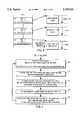
- FIG. 7is a flow chart of the operation of the status and descriptor queue according to an embodiment of the present invention.
- FIG. 8is a block diagram of a DMA controller constructed in accordance with an embodiment of the present invention.
- FIG. 1is a block diagram of a computer system constructed in accordance with an embodiment of the present invention.
- the systemcomprises a host computer 10 coupled to a DMA controller arrangement 12.
- the host computer 10includes a host central processing unit (CPU) 14 that operates as programmed by software, and a main (or host) memory 16 for the CPU 14. Both the CPU 14 and the main memory 16 are coupled to a system interface bus 18.
- the system interface bus 18can be a peripheral component interconnect (PCI) bus, or a conventional 64K (32 bit) system interface, for example.
- PCIperipheral component interconnect
- 64K32 bit
- the DMA controller arrangement 12has a plurality of DMA controllers 20 that provide multiple serial I/O channels of communication for direct memory access.
- each DMA controller 20provides multiple channels, although other embodiments of the invention provide DMA controllers that have single channels.
- the multiple channels of the multiple DMA controllers 20 of the DMA controller arrangement 12allow the computer system to interact with a plurality of different communication sources, such as disk controllers, SCSI controllers, parallel data ports, LANs, and WANs.
- FIG. 1Although shown in FIG. 1 as having multiple DMA controllers 20, certain embodiments of the present invention have only a single DMA controller 20 (such as shown, for example in FIG. 8) that has multiple channels.
- the software operated by the host CPU 14is responsible for identifying each DMA controller 20.
- the identifications of the DMA controllers 20 in FIGS. 1 and 2are arbitrary from the point of view of the DMA controllers 20. It is preferred, however, that the software assigns a unique identification to each DMA controller 20 in the common buffer pool group. This identification is placed in a register in each DMA controller 20.
- the registermay be an 8 bit register, for example.
- FIG. 2is a more detailed block diagram of the DMA controller arrangement 12 with a common buffer pool constructed in accordance with an embodiment of the present invention.
- the arrangement 12includes a descriptor queue (RDIx) 24, and a status queue (RSIx) 26.
- Each queue 24, 26has the same number of entries N as the number of buffers 28 that are initially available for use in receiving DMA transfers of data.
- the entries in the status queue 26provide indications of the status of corresponding ones of the buffers 28, as will be described below.
- the entries in the descriptor queue 24provide the starting address of the buffers 28.
- the softwaremust make certain that each DMA controller 20 in the daisy chain is programmed with the same start addresses for the descriptor queue 24 and status queue 26.
- the length of the descriptor queue 24 and the length of the status queue 26each represent the total number of entries, N. Both the descriptor queue 24 and the status queue 26 have the same N total entries, and the software makes certain that all DMA controllers 20 in the daisy chain of DMA controllers 20 sharing the common buffer pool are programmed with the same value of N. In certain alternative embodiments, however, the length of the descriptor queue 24 and the status queue 26 are different from each other.
- the buffer size, Bsize, for received packetsis fixed for all buffers 28 in the common buffer pool, although in other embodiments the buffer sizes may vary.
- the softwareprograms all of the DMA controllers 20 in the daisy chain sharing the common buffer pool with the same Bsize value.
- each such DMA controller 20is provided with its own descriptor queue and receive status queue.
- the DMA controllers 20never write into the descriptor queue 24.
- a DMA controller 20needs a buffer, that DMA controller 20 first looks at the status queue 26 to find a free buffer. Such a free buffer is indicated by the corresponding entry in the status queue 26. Once that DMA controller 20 finds a free entry, that DMA controller 20 (or channel within the DMA controller 20) immediately marks that entry as "in-use”. If the first entry the DMA controller 20 examines is not free (in-use or complete), then the channel of the DMA controller 20 keeps searching for the next free entry/buffer. If that channel of the DMA controller 20 searches completely around the ring of status queue 26 and fails to find a free buffer, then that DMA controller 20 alerts the software and other DMA controllers 20 that the entire common buffer pool is not available.
- the DMA controllers 20write and read the status queue 26.
- the softwarereads the status queue 26, and writes to the status queue 26 only for the purpose of clearing an entry, which marks the entry as free.
- Each entry in the status queuehas three possible entry status conditions: free, in-use, and complete.
- each entry in the status queuealso provides information regarding chip and channel identification, received frame length, received frame error conditions if any, and end-of-frame and beginning-of-frame status for chaining purposes.
- the free indicationis provided when both bits are clear.
- the softwarecan simply clear the entry in the status queue, and thereby indicate that the referenced buffer 28 is free.
- a single bitcan indicate the in-use status, and another bit can indicate the complete status.
- the DMA controllers 20should not allow both of these two bits to be set at the same time.
- FIG. 7is a flow chart of the operation of the status and descriptor queues (26, 24) according to an embodiment of the present invention.
- the software in step 40makes a buffer ready for data transfer, and stores the starting address for that buffer in an entry in the descriptor queue 24.
- the softwarealso clears the associated entry in the status queue 26, marking the entry and the corresponding buffer 28 "free". This means that the entry and the corresponding buffer 28 are available for use by any channel.
- a DMA controller 20claims the entry and corresponding buffer, and marks the entry "in-use".
- the in-use statusindicates that a channel of a DMA controller 20 has claimed that entry in the status queue and the corresponding buffer.
- the DMA controller 20After the DMA controller 20 has found the free entry, and marked the same entry as "in-use", then that DMA controller 20 reads from the corresponding entry in the descriptor queue in the descriptor queue 24.
- the DMA controller 20gets the start address of the free buffer from its reading of the entry in the descriptor queue.
- Datais received in the buffer 28 in step 44.
- the datamay be error free, or may contain errors.
- the entry status operationis independent of the quality of the received data.
- step 46the DMA controller 20 changes the entry in the status queue from "in-use” to "complete". Assume that a complete packet has been received, and that the packet length is equal to or less than the buffer size, Bsize. In this case the DMA controller 20 returns to the entry in the status queue 26, and writes this information into the entry in the status queue 26. The DMA controller 20 changes the status for that entry from "in-use” to "complete” as stated above.
- the complete statusindicates that the channel of the DMA controller 20 has received a packet into the buffer 28, and that the channel is moving to another entry in the status queue 26 and corresponding buffer 28.
- step 48the software will make use of the buffer data (step 48).
- a new buffer 28is then indicated as free in the entry in the status queue 26 that had previously been marked as complete.
- the DMA controller arrangementalso has a plurality of pointers and counters used in the management of the queues 24, 26. These include the software entry pointer SPt, the software buffer counter Scnt, the multi-chip entry pointer MPt, and the multi-chip buffer counter Mcnt.
- the countersare circular counters that are allowed to overflow. The counters are sufficiently large (e.g., 16 to 32 bits) so that there is no ambiguity. Whenever a DMA controller 20 channel claims a free buffer, that DMA controller 20 updates (increments) Mcnt by 1.
- the counters Scnt, Mcntare compared on a circular basis. This means that one counter could have an absolute value greater than the other counter, but actually be smaller on the circle. For example, assume that the counters are 16 bits long and that Mcnt has overflowed the 16 bit counter back to a value of 100. Also assume for this example that the Scnt has not yet overflowed the 16 bit counter, and is at a value of 63,000. In this case, Mcnt is ahead of Scnt even though the absolute values indicate Scnt as greater than Mcnt.
- the multi-chip entry pointer MPtpoints to the next likely free buffer 28 in the common buffer pool so that the other DMA controllers 20 (or channels in embodiments having a single DMA controller) may begin their search for a free buffer at the next most likely free buffer.
- the multi-chip entry pointer MPtis updated by a DMA controller 20 before that DMA controller 20 is allowed to place received data into the buffer 28 that it had claimed.
- the DMA controller 20writes the entry number of the entry it just found as free into MPt. This allows other DMA controllers 20 to start looking for the free buffer at the point where the last DMA controller 20 claimed the last entry. In other words, the next free entry is most likely to be at entry +1 from the number in MPt, and this is where the next DMA controller 20 will begin its search for a free buffer.
- the software pointer SPtpoints to the next entry in the status queue 26 that the software is ready to process.
- the software pointer SPtis updated by the software upon each use of a buffer corresponding to an entry in the status queue 26.
- the DMA controller 20In addition to updating the multi-chip entry pointer MPt prior to using the claimed buffer 28, the DMA controller 20 must also update the multi-chip buffer counter Mcnt by 1.
- the multi-chip buffer counter Mcntkeeps a count of the number of buffers 28 in the common buffer pool that have been claimed by one of the DMA controllers 20. As a function of this count and the count provided by the software counter Scnt, the total number of buffers available for use may be readily determined.
- the softwareis responsible to update the software entry pointer (SPt) and the software buffer counter (Scnt).
- SPtsoftware entry pointer
- Scntsoftware buffer counter
- the softwareclears the appropriate entry in the status queue 26, as described earlier. This marks that entry in the status queue 26 as free.
- the softwarewill then increment the software buffer counter Scnt by 1. If the software entry pointer SPt moved, the software updates SPt. This is described in more detail later.
- Mcnt-Scntallows the number of free buffers to be readily determined. In other embodiments, however, only one counter is provided. This single counter is incremented by the DMA controllers 20 and decremented by the software, or vice versa. This alternative embodiment allows the number of free buffers to be read directly from the single counter.
- All DMA controllers 20require access to the SPt and MPt pointers, and the Scnt and Mcnt counters. Accordingly, in preferred embodiments, these pointers and counters reside in the main memory 16 outside the DMA controllers 20 as shown in FIG. 1. Alternatively, these pointers and counters could instead reside in one or more DMA controllers 20 with a method to share them among the DMA controller 20.
- each packetis received in sequence. The beginning and end of a packet completely precedes all subsequent packets.
- packet arrival for one channelis "packet sequence orderly".
- packetsarrive at different times.
- one descriptor segmentmay complete before some or all of its predecessors. Sequenced packet arrival is therefore not orderly. This problem is further exacerbated by the fact that different channels have different speeds (and protocols).
- single channel descriptor ring architecturesthe descriptors in a descriptor ring are kept contiguous.
- FIG. 3is a schematic diagram of the receive descriptor queue 24 of FIG. 2, but in a ring form.
- non-contiguous buffersallow full use of free buffers in the presence of multiple channels where packet arrival is highly varied from channel to channel. Also, non-contiguous buffers allow multiple buffers on the same channel for the same frame to be claimed.
- FIGS. 5A-Eare schematic depictions of the status queue 26 (in the form of a ring for illustration purposes) during various stages of operation according to an embodiment of the present invention.
- the software entry pointer SPt and the multi-chip entry pointer MPtboth point to the start of the descriptor queue 24 and the status queue 26.
- the eight channelsare identified as A through H.
- the total number of descriptor queue 24is 64 and the total number of status queue 26 is 64.
- the counts Scnt and Mcntare equal, and can be zero, for example.
- the pointers SPt and MPtboth point to the head of the status queue 26 and the descriptor queue 24.
- Using the difference count between Scnt and Mcntprovides a significant advantage.
- These countersprovide a fast method for the DMA controller 20 to determine the total number of free queue.
- the total size of the status queue 26, in segments, minus the difference count (Mcnt-Scnt)is equal to the number of free buffers/queue entries.
- the number of free buffers/queue entriesis therefore given by the equation:
- the softwareensures that all the buffers/queue entries are free at initialization, and updates the Scnt buffer counter each time a buffer/queue entry is made free.
- the softwareneed not keep an accurate update of the Scnt. The consequence of this is that the DMA controller 20 does not know how many buffers are available. The present invention is still operative, however, even without an accurate software buffer Scnt.
- the eight channelsare set up for receiving. This is depicted in FIG. 5B with the arbitrary assumption that the eight channels are set up with chip/channel identifications A through H. Each channel marks its entry in the status queue 26 as "in-use”.
- the number of free buffers/queue entriesis the total number of entries in the status queue 26 (or descriptor queue 24) less the total number of activated channels. Also, when the software has had a chance to use all of the received packets, the number of free buffers/queue entries is once again the total number of entries in the status queue 26 (or descriptor queue 24) less the total number of activated channels. Furthermore, the number of free buffers/queue entries decreases as packets are received and wait for the software to free that entry.
- Certain preferred embodiments of the present inventionprovide for equal access among the DMA controllers/channels desiring use of the common buffer pool.
- each DMA controller 20appears as just another peripheral requesting DMA master access.
- DMA data accessrefers to an access for transferring receive data into a buffer 28, or transferring transmit data from a buffer 28.
- DNA queue accessrefers to an access to the queue (descriptor queue 24 and status queue 26) and the pointers/counters (SPt, MPt, Scnt, Mcnt).
- the term "access”itself means a memory read or write.
- each DMA controller 20can attempt to gain DMA queue access at a time.
- each DMA controller 20must go through two steps. First, that DMA controller 20 must gain the right of bus mastership over all the other DMA controllers 20. Second, the DMA controller 20 must gain bus mastership through the normal request/grant procedure for bus master control access.
- a DMA controller 20when a DMA controller 20 wants DMA queue access right, that DMA controller 20 asserts a low signal on a negotiation line (MNLine in FIG. 2). If an acknowledge in (MAckIn) signal level is high, then that DMA controller 20 drives an acknowledge out (MAckOut) signal level low. The DMA controller 20 then temporarily has the sole right among other DMA controllers 20 for DMA mastership. When that DMA controller 20 finishes its DMA, it releases the MNLine and drives the acknowledge out (MAckOut) signal level high. That DMA controller 20 is not allowed to gain another DMA queue access right until MNLine line goes inactive (high) again.
- MNLinenegotiation line
- a DMA controller 20may perform a series of DMA accesses. For example, that DMA controller 20 may need to update the current entry in the status queue 26, and then obtain the next available entry from the status queue 26. The DMA controller 20 then needs to set up the next receive buffer from the corresponding entry in the descriptor queue 24. That DMA controller 20 will most likely hold the DMA right from other DMA controllers 20 until these tasks are finished.
- a DMA controller 20gains the DMA right from other DMA controllers 20, then gains system interface bus mastership through the request/grant to update status queue 26.
- the DMA controller 20would give up DMA mastership, but not the DMA right from other DMA controllers 20, to prepare to find the next available entry from status queue 26.
- the DMA controller 20relinquishes mastership, and regains mastership to set up the next receive buffer. However, the DMA controller 20 does not necessarily relinquish the DMA queue access right.
- the DMA controllers 20are only able to gain the right from other DMA controllers 20 one channel at a time. In other embodiments, however, exceptions are provided for certain programmed high priority channels so that a particular DMA controller 20 would obtain the DMA right for more than one channel at a time.
- FIG. 8is a block diagram of a DMA controller 20 constructed in accordance with an embodiment of the present invention.
- the DMA controller 20is coupled to the system interface bus 18 by a bus interface controller 90.
- the DMA controller 20has an on-chip controller or state machine 92. After initialization by the host CPU 14, the on-chip controller 92 selects a particular serial I/O (SIO) channel to prepare that SIO channel 94 to be ready to receive.
- the DMA controller 20accesses the descriptor queue 24 using a pointer control 96 and an arbitration unit 98.
- the pointer controlprovides the control of the descriptor queue 24 and the status queue 26.
- the arbitration unitprovides bus access arbitration, and channel and chip arbitration.
- the DMA controller 20obtains the starting address for the receive buffer 28.
- a maximum buffer size, Bsizewill have been programmed into the on-chip controller 92 by the host CPU 14.
- the particular SIO channel 94 selectedis ready to place receive data into the host main memory 16 (FIG. 1).
- the on-chip controller 92repeats the above procedure to set up each SIO channel 94.
- the number of channels on the chipmay be any number, although certain preferred embodiments have eight channels.
- the selected SIO channel 94first looks for a beginning of frame delimiter in the data stream.
- Frame delimitersare well known to those of skill in the art, and include flags and/or synchronization (SYN) characters.
- SYNsynchronization
- the data FIFO and controller 100move the received data through the FIFO to the bus interface controller 90.
- the arbitration unit 98acquires bus mastership of the high speed bus through the bus interface controller 90.
- the FIFO dataare then passed through the bus interface controller 90 and the system interface bus 18 to be written into the receive buffer 28 in main memory 16.
- the memory address pointer in a buffer control 102is incremented to maintain the correct write location.
- the buffer control 102increments a byte counter for each byte written to main memory 16.
- the arbitration unitacquires the DMA right to access the status queue 26 from other channels and other DMA controller chips in those embodiments having multiple DMA controllers 20.
- the arbitration unitAfter gaining the DMA right, the arbitration unit then acquires bus mastership of the system interface bus 18, and writes the completed frame status into the appropriate entry of the status queue 26.
- the frame statusincludes the total frame byte count (from the byte counter in the buffer control 102), a byte to indicate "good” or "error” received data, and other protocol specific information such as address matches, residual bit, or other types of information.
- the arbitration unit 98 and the on-chip controller 92then access the next available entry in the descriptor queue 24. From the descriptor queue 24, the DMA controller 20 obtains the start address for the receive buffer 28, and that particular SIO channel 94 is ready to write a new received frame into a new receive buffer 28.
- FIG. 4is a flow chart that explains the operation of the invention from the point of view of a single channel receiving a flow of data. This description applies to packet based data. The receipt of asynchronous (start-stop) data that may not have complete packets identified nor may not completely fill a buffer is only partially described.
- the channel in a DMA controller 20searches for a free buffer 28, marks that buffer 28 in the corresponding entry in the status queue as in-use, and prepares to receive data into that buffer 28.
- Buffer acquisitionrequires that the DMA controller 20 gain the DMA right from the other DMA controllers 20 as described earlier (for those embodiments having multiple DMA controllers 20).
- a DMA controller 20 channelis not required to obtain the DMA right from other DMA controllers 20. Receive data are allowed to go into the buffer memory with normal bus request/grant procedures, and no additional right from other DMA controllers 20 is required.
- the DMA controller 20 channelreleases the descriptor queue 24 and status queue 26 and marks that buffer/queue entry as complete. Buffer release requires that the DMA controller 20 gain the DMA right from the other DMA controllers 20.
- step 50a specific DMA controller 20 negotiates for the right for DMA queue access from other DMA controllers 20 that share the common buffer pool.
- step 52the DMA controller 20 accesses and examines the entry in the status queue pointed to by MPt +1, the multi-chip entry pointer plus one. If the buffer 28 corresponding to the entry in the status queue is not free, then the next entry in the status queue is examined in step 56.
- step 58It is next determined in step 58 whether the status queue 26 is wrapped-around, and if not, the next entry in the status queue is examined (step 52). If the set is wrapped-around, then the software and the other DMA controllers 20 are notified that the status queue 26 is full (step 60). The DMA controller 20 then releases the right for DMA queue access from the other DMA controllers 20 (step 62).
- step 64the DMA controller marks the entry in the status queue as in-use, the pointer MPT +1 is updated, the Mcnt is incremented by 1, the corresponding entry in the descriptor queue 24 is accessed, and the receive buffer 28 is set up.
- the DMA controller 28then releases the right for DMA queue access from other DMA controllers 20 in step 66.
- the DMA controller 20prepares the buffer 28 to receive the data (step 68), the buffer 28 waits for the packet of data in step 70, and the buffer receives the packet with DMA data access in step 72.
- step 74it is determined whether the end of the packet of data has been reached. If not, then it is determined (step 76) whether the buffer is full. The receiving of data continues in step 72 if the buffer is not full and the end of the packet of data has not been reached. However, if the buffer is full, it is next determined whether the packet end coincides with the full buffer (step 78). If not, then it is determined whether buffer chaining is allowed (step 80).
- the DMA controller 20negotiates for the right for DMA queue access from other DMA controllers 20, in step 82.
- the DMA controller 20updates the entry in the status queue corresponding to the buffer 28 that was filled and marks the entry in the status queue as complete in step 84.
- step 86the DMA controller 20 notifies the software of a receive buffer overflow condition. It also negotiates for the right for DMA queue access and marks the corresponding entry in the status queue as complete, and then releases the right for DMA queue access. The DMA controller 20 then terminates further receiving of the data packet. The channel of the DMA controller 20 is then able to receive new packets after the end of the current data packet (step 88).
- Each DMA controller 20has a designated control bit that specifically allows or disallows buffer chaining. If chaining is disallowed, and a packet is received that exceeds Bsize, then there is a buffer overflow, and that DMA controller 20 reports the overflow condition as one of the received frame error conditions.
- Full packets received within one Bsize bufferhave both beginning-of-frame (BOF) and end-of-frame (EOF) set in the appropriate status queue entry. If chaining is allowed, when a packet of greater length than Bsize is received, the DMA controller 20 marks the entry in the status queue as complete with BOF set and EOF clear. The DMA controller 20 then looks for another free buffer while the current frame is being received. Thus, in these embodiments, an adequate amount of FIFO buffering is allocated for chaining so that the DMA controller 20 can switch from one buffer to another while data are coming in on the receiver.
- Each individual channelis selectable for use with chaining.
- the softwareglobally selects all channels to allow chaining or disallow chaining.
- the softwareis able to individually select each channel for either chaining allowed or disallowed.
- the total receive frame lengthis the sum of the receive lengths of all the chain segments. For software convenience, the DMA controller 20 keeps track of the total frame length, and places that value in the last entry for that frame.
- FIG. 6depicts an example of chaining according to an embodiment of the present invention.
- a DMA controller 20designated B
- the packetis 717 bytes long, and the fixed Bsize is 256 bytes.
- DMA controller 20 (B)first sets up channel 3 to cause data to be received into the buffer corresponding to entry number 18 in the status queue 26. After filling the buffer corresponding to entry number 18, assume that the buffers corresponding to entry numbers 19 through 28 are taken by other DMA controllers 20 and/or channels. Thus, DMA controller 20 (B) then sets up channel 3 to continue receiving that packet into the buffer that corresponds to entry number 29 in the status queue 26. After this buffer is filled, assume that the buffers 30, 31, and 32 corresponding to entry numbers 30, 31 and 32 have been taken, so DMA controller 20 (B) sets up channel 3 to receive data into the buffer corresponding to entry number 33.
- the DYA controller 20reports the completion of the received packet, and writes the frame length into entry number 33 in the status queue 26.
- the softwareis responsible to sequentially trace the chained buffers in order to reconstruct the packet.
Landscapes
- Engineering & Computer Science (AREA)
- Theoretical Computer Science (AREA)
- Physics & Mathematics (AREA)
- General Engineering & Computer Science (AREA)
- General Physics & Mathematics (AREA)
- Bus Control (AREA)
Abstract
Description
The present application is related to U.S. patent application Ser. No. 08/536,729, filed on Sep. 29, 1995, still pending.
The present application is related to U.S. patent application Ser. No. 08/536,729, filed on Sep. 29, 1995, still pending.
The present invention relates to the field of data transfers in computer systems, and more particularly, to a central processing unit (CPU) controlled system that passes data over a CPU bus using a plurality of direct memory access (DMA) channels.
In a digital computer, a CPU operates on data stored in a main memory. Since there are practical size limitations on the main memory, bulk memory storage devices are provided in addition to and separately from the main memory. When the CPU wants to make use of data stored in bulk storage, for example, a hard disk, the data is moved from the hard disk into the main memory. This movement of blocks of memory inside the computer is a very time consuming process and would severely hamper the performance of the computer system if the CPU were to control the memory transfers itself.
In order to relieve the CPU from the chore of controlling the movement of blocks of memory inside the computer, a direct memory access (DMA) controller is normally used. The DMA controller receives information from the CPU as to the base location from where bytes are to be moved, the address to where these bytes should go, and the number of bytes to move. Once it has been programmed by the CPU, the DMA controller oversees the transfer of the memory data within the computer system. Normally, DMA operations are used to move data between input/output (I/O) devices and memory. During the transfer, the data is temporarily stored in buffers.
There are at least two basic types of DMA buffer management schemes: circular queue and linked list. In circular queue, descriptors are maintained in a ring structure. In a linked list, a sequence of buffers is maintained connected one to another.
The LANCE chip architecture manufactured by Advanced Micro Devices of Sunnyvale, Calif. provides one example of circular queue DMA management. The 68605X.25 chip manufactured by Motorola of Schaumberg, Ill. is an example of a chip using the linked list method. Still another DMA buffer management method is that used by Cirrus Logic of Fremont, Calif. in their CD24xx product family, in which A/B buffering provides a double buffering mechanism.
All the above examples are methods of DMA buffer management for one channel. For example, each CD24xx chip has four full duplex channels. Thus, a CD24xx could have as many as eight DMA paths: four transmit and four receive. However, each transmit and receive DMA channel is provided with its own separate A/B buffering scheme. Thus, even though it has multiple channels, the CD24xx is an example of single channel DMA buffer management.
In modern systems, there are often many paths provided for data transfers to and from the system. Data transfers with the system may involve, for example: disk controllers, SCSI controllers, parallel data ports, LANs, and WANs. Hence, it is advantageous to provide a computer system with multiple communication channels. However, for those applications that need multiple communication channels, the provision of separate DMA buffering management for each channel is not efficient. A traditional single channel DMA approach for multiple channels causes excessive overhead for the host CPU. This is due in part to the separate pointers and control/status methods that are maintained for each channel.
There is therefore a need for a DMA controller arrangement that provides multiple channels without requiring excessive overhead to support the buffer management.
This and other needs are met by the present invention which provides a computer system having multi-channel direct memory access (DMA), comprising a host computer having a processor that runs software and a main memory, a system interface bus coupling the host computer and the main memory, and a multi-channel DMA controller arrangement coupled to the system interface bus. The DMA controller arrangement has multiple input/output (I/O) channels and a common buffer pool having a plurality of buffers accessible to each of the multiple channels for buffering data transferred to or from the host computer.
The provision of a computer system having a DMA controller arrangement with multiple I/O channels but a common buffer pool according to the present invention, permits the proper amount of buffers to be utilized as needed. For example, if more buffers are needed on a particular channel, they are available in the common buffer pool. The use of a common buffer pool also reduces the number of circular queues and pointers, since each channel does not need its own circular queue and pointer.
The earlier stated needs are also met by another aspect of the present invention which provides a method of performing direct memory access (DMA) in a system having a DMA controller arrangement with multiple DMA channels and a common pool of buffers. The method comprises the steps of maintaining a status queue, with each entry in the status queue indicating whether a corresponding buffer from the common pool of buffers is a free buffer available for use by one of the DMA channels in a DiA transaction. When a DMA transaction is to occur over one of the DMA channels, the status queue is searched for an entry which indicates whether its corresponding buffer is a free buffer. The entry in the status queue and the free buffer are claimed by the DMA channel when the entry in the status queue with the corresponding free buffer is found. A starting address of the free buffer is then determined, and data is then buffered within the free buffer.
The method of the present invention permits non-contiguous buffers. The ability to search for a free buffer allows multiple channels with different speeds to co-exist in the computer system without a slow channel completely foreclosing the use of the buffers by other channels. If a slower channel is currently filling up a number of buffers with data, there may be embedded free buffers in the common buffer pool that have been freed for use by the software. The searching feature of the present invention identifies such free buffers that are then claimed by other DMA channels for filling with data.
The foregoing and other features, aspects and advantages of the present invention will become more apparent from the following detailed description of the present invention when taken in conjunction with the accompanying drawings.
FIG. 1 is a block diagram of a computer system constructed in accordance with an embodiment of the present invention.
FIG. 2 is a block diagram of a DMA controller arrangement with a common buffer pool constructed in accordance with an embodiment of the present invention.
FIG. 3 is a schematic diagram of a descriptor queue ring.
FIG. 4 is a flow chart of a buffer acquisition sequence and a buffer use and release sequence for a single channel in accordance with an embodiment of the present invention.
FIGS. 5A-E are schematic depictions of a status queue ring during various stages of operation according to an embodiment of the present invention.
FIG. 6 is a schematic diagram of an example of chaining of buffers in accordance with an embodiment of the present invention.
FIG. 7 is a flow chart of the operation of the status and descriptor queue according to an embodiment of the present invention.
FIG. 8 is a block diagram of a DMA controller constructed in accordance with an embodiment of the present invention.
FIG. 1 is a block diagram of a computer system constructed in accordance with an embodiment of the present invention. The system comprises ahost computer 10 coupled to aDMA controller arrangement 12. Thehost computer 10 includes a host central processing unit (CPU) 14 that operates as programmed by software, and a main (or host)memory 16 for theCPU 14. Both theCPU 14 and themain memory 16 are coupled to asystem interface bus 18. Thesystem interface bus 18 can be a peripheral component interconnect (PCI) bus, or a conventional 64K (32 bit) system interface, for example.
TheDMA controller arrangement 12 has a plurality ofDMA controllers 20 that provide multiple serial I/O channels of communication for direct memory access. In the embodiment of FIG. 1, eachDMA controller 20 provides multiple channels, although other embodiments of the invention provide DMA controllers that have single channels. The multiple channels of themultiple DMA controllers 20 of theDMA controller arrangement 12 allow the computer system to interact with a plurality of different communication sources, such as disk controllers, SCSI controllers, parallel data ports, LANs, and WANs.
Although shown in FIG. 1 as havingmultiple DMA controllers 20, certain embodiments of the present invention have only a single DMA controller 20 (such as shown, for example in FIG. 8) that has multiple channels.
The following description of an exemplary embodiment is applied to multiple receivers of data. However, one of ordinary skill in the art will appreciate that the invention is applicable in a symmetrical fashion for multiple transmitters.
The software operated by thehost CPU 14 is responsible for identifying eachDMA controller 20. The identifications of theDMA controllers 20 in FIGS. 1 and 2 (A, B, X) are arbitrary from the point of view of theDMA controllers 20. It is preferred, however, that the software assigns a unique identification to eachDMA controller 20 in the common buffer pool group. This identification is placed in a register in eachDMA controller 20. The register may be an 8 bit register, for example.
FIG. 2 is a more detailed block diagram of theDMA controller arrangement 12 with a common buffer pool constructed in accordance with an embodiment of the present invention. In addition to themultiple DMA controllers 20, thearrangement 12 includes a descriptor queue (RDIx) 24, and a status queue (RSIx) 26. Eachqueue buffers 28 that are initially available for use in receiving DMA transfers of data. The entries in thestatus queue 26 provide indications of the status of corresponding ones of thebuffers 28, as will be described below. The entries in thedescriptor queue 24 provide the starting address of thebuffers 28.
Since themultiple DMA controllers 20 share the common buffer pool, the software must make certain that eachDMA controller 20 in the daisy chain is programmed with the same start addresses for thedescriptor queue 24 andstatus queue 26.
The length of thedescriptor queue 24 and the length of thestatus queue 26 each represent the total number of entries, N. Both thedescriptor queue 24 and thestatus queue 26 have the same N total entries, and the software makes certain that allDMA controllers 20 in the daisy chain ofDMA controllers 20 sharing the common buffer pool are programmed with the same value of N. In certain alternative embodiments, however, the length of thedescriptor queue 24 and thestatus queue 26 are different from each other.
The buffer size, Bsize, for received packets is fixed for allbuffers 28 in the common buffer pool, although in other embodiments the buffer sizes may vary. The software programs all of theDMA controllers 20 in the daisy chain sharing the common buffer pool with the same Bsize value.
When one or more of themultiple DMA controllers 20 are not to be connected with a common buffer pool, as in certain embodiments, then eachsuch DMA controller 20 is provided with its own descriptor queue and receive status queue.
In operation, theDMA controllers 20 never write into thedescriptor queue 24. When aDMA controller 20 needs a buffer, thatDMA controller 20 first looks at thestatus queue 26 to find a free buffer. Such a free buffer is indicated by the corresponding entry in thestatus queue 26. Once thatDMA controller 20 finds a free entry, that DMA controller 20 (or channel within the DMA controller 20) immediately marks that entry as "in-use". If the first entry theDMA controller 20 examines is not free (in-use or complete), then the channel of theDMA controller 20 keeps searching for the next free entry/buffer. If that channel of theDMA controller 20 searches completely around the ring ofstatus queue 26 and fails to find a free buffer, then thatDMA controller 20 alerts the software andother DMA controllers 20 that the entire common buffer pool is not available.
In contrast to thedescriptor queue 24, theDMA controllers 20 write and read thestatus queue 26. The software reads thestatus queue 26, and writes to thestatus queue 26 only for the purpose of clearing an entry, which marks the entry as free.
Each entry in the status queue has three possible entry status conditions: free, in-use, and complete. In certain embodiments, each entry in the status queue also provides information regarding chip and channel identification, received frame length, received frame error conditions if any, and end-of-frame and beginning-of-frame status for chaining purposes.
In order to distinguish three entry status conditions, at least two bits are required. In an exemplary embodiment, the free indication is provided when both bits are clear. Hence, the software can simply clear the entry in the status queue, and thereby indicate that the referencedbuffer 28 is free. A single bit can indicate the in-use status, and another bit can indicate the complete status. TheDMA controllers 20 should not allow both of these two bits to be set at the same time.
FIG. 7 is a flow chart of the operation of the status and descriptor queues (26, 24) according to an embodiment of the present invention. After software initialization, the software instep 40 makes a buffer ready for data transfer, and stores the starting address for that buffer in an entry in thedescriptor queue 24. The software also clears the associated entry in thestatus queue 26, marking the entry and the correspondingbuffer 28 "free". This means that the entry and the correspondingbuffer 28 are available for use by any channel.
Instep 42, at some later time in operation, aDMA controller 20 claims the entry and corresponding buffer, and marks the entry "in-use". The in-use status indicates that a channel of aDMA controller 20 has claimed that entry in the status queue and the corresponding buffer. After theDMA controller 20 has found the free entry, and marked the same entry as "in-use", then thatDMA controller 20 reads from the corresponding entry in the descriptor queue in thedescriptor queue 24. TheDMA controller 20 gets the start address of the free buffer from its reading of the entry in the descriptor queue.
Data is received in thebuffer 28 instep 44. The data may be error free, or may contain errors. The entry status operation, however, is independent of the quality of the received data.
Instep 46, theDMA controller 20 changes the entry in the status queue from "in-use" to "complete". Assume that a complete packet has been received, and that the packet length is equal to or less than the buffer size, Bsize. In this case theDMA controller 20 returns to the entry in thestatus queue 26, and writes this information into the entry in thestatus queue 26. TheDMA controller 20 changes the status for that entry from "in-use" to "complete" as stated above. The complete status indicates that the channel of theDMA controller 20 has received a packet into thebuffer 28, and that the channel is moving to another entry in thestatus queue 26 and correspondingbuffer 28.
At a later point in time, the software will make use of the buffer data (step 48). Anew buffer 28 is then indicated as free in the entry in thestatus queue 26 that had previously been marked as complete.
Returning to FIG. 2, the DMA controller arrangement also has a plurality of pointers and counters used in the management of thequeues DMA controller 20 channel claims a free buffer, thatDMA controller 20 updates (increments) Mcnt by 1.
The counters Scnt, Mcnt are compared on a circular basis. This means that one counter could have an absolute value greater than the other counter, but actually be smaller on the circle. For example, assume that the counters are 16 bits long and that Mcnt has overflowed the 16 bit counter back to a value of 100. Also assume for this example that the Scnt has not yet overflowed the 16 bit counter, and is at a value of 63,000. In this case, Mcnt is ahead of Scnt even though the absolute values indicate Scnt as greater than Mcnt.
The multi-chip entry pointer MPt points to the next likelyfree buffer 28 in the common buffer pool so that the other DMA controllers 20 (or channels in embodiments having a single DMA controller) may begin their search for a free buffer at the next most likely free buffer. The multi-chip entry pointer MPt is updated by aDMA controller 20 before thatDMA controller 20 is allowed to place received data into thebuffer 28 that it had claimed. TheDMA controller 20 writes the entry number of the entry it just found as free into MPt. This allowsother DMA controllers 20 to start looking for the free buffer at the point where thelast DMA controller 20 claimed the last entry. In other words, the next free entry is most likely to be at entry +1 from the number in MPt, and this is where thenext DMA controller 20 will begin its search for a free buffer.
The software pointer SPt points to the next entry in thestatus queue 26 that the software is ready to process. The software pointer SPt is updated by the software upon each use of a buffer corresponding to an entry in thestatus queue 26.
In addition to updating the multi-chip entry pointer MPt prior to using the claimedbuffer 28, theDMA controller 20 must also update the multi-chip buffer counter Mcnt by 1. The multi-chip buffer counter Mcnt keeps a count of the number ofbuffers 28 in the common buffer pool that have been claimed by one of theDMA controllers 20. As a function of this count and the count provided by the software counter Scnt, the total number of buffers available for use may be readily determined.
As the software uses thebuffers 28 andqueues buffer 28, and has made the corresponding entry in the status queue ready with anew buffer 28, then the software clears the appropriate entry in thestatus queue 26, as described earlier. This marks that entry in thestatus queue 26 as free. The software will then increment the software buffer counter Scnt by 1. If the software entry pointer SPt moved, the software updates SPt. This is described in more detail later.
The difference count, Mcnt-Scnt, allows the number of free buffers to be readily determined. In other embodiments, however, only one counter is provided. This single counter is incremented by theDMA controllers 20 and decremented by the software, or vice versa. This alternative embodiment allows the number of free buffers to be read directly from the single counter.
An ambiguity exists when SPt=MPt. In this case, thestatus queue 26 and buffers 28 could be totally wrapped-around or totally free. The term "totally wrapped-around" does not necessarily mean that there are no free buffers. The ring could have totally wrapped-around, but there could be embedded free buffers. This ambiguity is eliminated by comparison of the counters Scnt and Mcnt, which reveals whether there are any free, embedded buffers.
AllDMA controllers 20 require access to the SPt and MPt pointers, and the Scnt and Mcnt counters. Accordingly, in preferred embodiments, these pointers and counters reside in themain memory 16 outside theDMA controllers 20 as shown in FIG. 1. Alternatively, these pointers and counters could instead reside in one ormore DMA controllers 20 with a method to share them among theDMA controller 20.
When multiple channels share the DMA structure, there are special problems. In a single channel DMA receiver, each packet is received in sequence. The beginning and end of a packet completely precedes all subsequent packets. In other words, in any single channel DMA structure, the packet arrival for one channel is "packet sequence orderly". However, for multiple channels, packets arrive at different times. Thus, one descriptor segment may complete before some or all of its predecessors. Sequenced packet arrival is therefore not orderly. This problem is further exacerbated by the fact that different channels have different speeds (and protocols). In single channel descriptor ring architectures, the descriptors in a descriptor ring are kept contiguous. If the descriptors are kept contiguous in a multi-channel ring, then a slow channel could keep one descriptor segment busy while the rest of the ring looped back around. In this case, there would be free buffers available for use in a DMA transfer, but after the slow descriptor. In order to be efficient, therefore, the present invention provides for the re-use of embedded descriptors. Such embedded descriptors are depicted in FIG. 3, which is a schematic diagram of the receivedescriptor queue 24 of FIG. 2, but in a ring form.
Assume that a multi-channel descriptor ring has "wrapped around" during operation. This means that the total number of packets collectively received by all channels is equal to the number of descriptors in the ring. Suppose that Channel X is rather slow (perhaps 1200 or 2400 bps while the other channels are 115.2 Kbps and higher up to 2 Mbps). During the time that those packets were received, the software used the information in some of the receive buffers. The software then freed those corresponding descriptors with associated buffers. However, if Channel X had a rather long and slow packet on its receiver,when the ring would be considered full when the ring wrapped around to the descriptor being used by Channel X. The DMA control arrangement described above permits "jumping over" used descriptors, and making use of ring embedded free buffers. Another way of stating this is that the present invention provides a DMA structure with non-contiguous buffers.
One of the advantages of non-contiguous buffers is that they allow full use of free buffers in the presence of multiple channels where packet arrival is highly varied from channel to channel. Also, non-contiguous buffers allow multiple buffers on the same channel for the same frame to be claimed.
The following is a description of the receive queue operation of the present invention. In this example, a single eight channel DMA controller arrangement is provided, with a common receive buffer pool. FIGS. 5A-E are schematic depictions of the status queue 26 (in the form of a ring for illustration purposes) during various stages of operation according to an embodiment of the present invention. At initialization (FIG. 5A), the software entry pointer SPt and the multi-chip entry pointer MPt both point to the start of thedescriptor queue 24 and thestatus queue 26. The eight channels are identified as A through H. In this exemplary embodiment, the total number ofdescriptor queue 24 is 64 and the total number ofstatus queue 26 is 64.
At immediate initialization, the counts Scnt and Mcnt are equal, and can be zero, for example. The pointers SPt and MPt both point to the head of thestatus queue 26 and thedescriptor queue 24. Using the difference count between Scnt and Mcnt provides a significant advantage. These counters provide a fast method for theDMA controller 20 to determine the total number of free queue. The total size of thestatus queue 26, in segments, minus the difference count (Mcnt-Scnt) is equal to the number of free buffers/queue entries. The number of free buffers/queue entries is therefore given by the equation:
FREE.sub.-- B=status queue size-(Mcnt-Scnt)
In preferred embodiments, the software ensures that all the buffers/queue entries are free at initialization, and updates the Scnt buffer counter each time a buffer/queue entry is made free. However, in other embodiments, the software need not keep an accurate update of the Scnt. The consequence of this is that theDMA controller 20 does not know how many buffers are available. The present invention is still operative, however, even without an accurate software buffer Scnt.
Continuing with the receive queue example, the eight channels are set up for receiving. This is depicted in FIG. 5B with the arbitrary assumption that the eight channels are set up with chip/channel identifications A through H. Each channel marks its entry in thestatus queue 26 as "in-use".
Assume that complete packets are received on channels D and G at approximately the same time. Then the previous buffers/queue entries used by D and G are made complete, and those channels search for new free buffers/queue (FIG. 5C). When the software eventually uses those two received buffers, the buffers/queue entries for D and G are then made free (FIG. 5D). Now assume that the packet on channel A is complete, and that the software has used that packet and makes the previous buffer/queue entry free (FIG. 5E).
This example of operation highlights some of the characteristics of the present invention. Immediately after initialization, the number of free buffers/queue entries is the total number of entries in the status queue 26 (or descriptor queue 24) less the total number of activated channels. Also, when the software has had a chance to use all of the received packets, the number of free buffers/queue entries is once again the total number of entries in the status queue 26 (or descriptor queue 24) less the total number of activated channels. Furthermore, the number of free buffers/queue entries decreases as packets are received and wait for the software to free that entry.
Since certain embodiments of the present invention provide multiple chips and multiple channels that share a common resource, in this case a common buffer pool, there needs to be some method of regulating the access to the pool by the multiple DMA controllers/channels. Certain preferred embodiments of the present invention provide for equal access among the DMA controllers/channels desiring use of the common buffer pool.
In the present invention, there are two levels of "mastership". The first is the normal bus mastership which aDMA controller 20 needs to obtain to perform transfers over thesystem interface bus 18. The second is the "right" to the descriptor andstatus queue MA controllers 20. ADMA controller 20 performing data transfer to or from abuffer 28 does not need a right fromother DMA controllers 20 to do so. For buffer data transfer, eachDMA controller 20 appears as just another peripheral requesting DMA master access. For clarification purposes, the following terms, "DMA data access" and "DMA queue access", will be defined. "DMA data access" refers to an access for transferring receive data into abuffer 28, or transferring transmit data from abuffer 28. "DNA queue access" refers to an access to the queue (descriptor queue 24 and status queue 26) and the pointers/counters (SPt, MPt, Scnt, Mcnt). The term "access" itself means a memory read or write.
In the present invention, only oneDMA controller 20 can attempt to gain DMA queue access at a time. To gain mastership of the hostsystem interface bus 18 for DMA queue access, eachDMA controller 20 must go through two steps. First, thatDMA controller 20 must gain the right of bus mastership over all theother DMA controllers 20. Second, theDMA controller 20 must gain bus mastership through the normal request/grant procedure for bus master control access.
In preferred embodiments, when aDMA controller 20 wants DMA queue access right, thatDMA controller 20 asserts a low signal on a negotiation line (MNLine in FIG. 2). If an acknowledge in (MAckIn) signal level is high, then thatDMA controller 20 drives an acknowledge out (MAckOut) signal level low. TheDMA controller 20 then temporarily has the sole right amongother DMA controllers 20 for DMA mastership. When thatDMA controller 20 finishes its DMA, it releases the MNLine and drives the acknowledge out (MAckOut) signal level high. ThatDMA controller 20 is not allowed to gain another DMA queue access right until MNLine line goes inactive (high) again.
Once aDMA controller 20 has the DMA right over allother DMA controllers 20, thatDMA controller 20 may perform a series of DMA accesses. For example, thatDMA controller 20 may need to update the current entry in thestatus queue 26, and then obtain the next available entry from thestatus queue 26. TheDMA controller 20 then needs to set up the next receive buffer from the corresponding entry in thedescriptor queue 24. ThatDMA controller 20 will most likely hold the DMA right fromother DMA controllers 20 until these tasks are finished.
In other words, aDMA controller 20 according to certain embodiments of the present invention, gains the DMA right fromother DMA controllers 20, then gains system interface bus mastership through the request/grant to updatestatus queue 26. TheDMA controller 20 would give up DMA mastership, but not the DMA right fromother DMA controllers 20, to prepare to find the next available entry fromstatus queue 26. TheDMA controller 20 relinquishes mastership, and regains mastership to set up the next receive buffer. However, theDMA controller 20 does not necessarily relinquish the DMA queue access right.
In preferred embodiments, theDMA controllers 20 are only able to gain the right fromother DMA controllers 20 one channel at a time. In other embodiments, however, exceptions are provided for certain programmed high priority channels so that aparticular DMA controller 20 would obtain the DMA right for more than one channel at a time.
FIG. 8 is a block diagram of aDMA controller 20 constructed in accordance with an embodiment of the present invention. TheDMA controller 20 is coupled to thesystem interface bus 18 by abus interface controller 90. TheDMA controller 20 has an on-chip controller or state machine 92. After initialization by thehost CPU 14, the on-chip controller 92 selects a particular serial I/O (SIO) channel to prepare thatSIO channel 94 to be ready to receive. TheDMA controller 20 accesses thedescriptor queue 24 using apointer control 96 and anarbitration unit 98. The pointer control provides the control of thedescriptor queue 24 and thestatus queue 26. The arbitration unit provides bus access arbitration, and channel and chip arbitration.
From thedescriptor queue 24, theDMA controller 20 obtains the starting address for the receivebuffer 28. A maximum buffer size, Bsize, will have been programmed into the on-chip controller 92 by thehost CPU 14. After theDMA controller 20 has the starting buffer address and maximum buffer size, theparticular SIO channel 94 selected is ready to place receive data into the host main memory 16 (FIG. 1).
The on-chip controller 92 repeats the above procedure to set up eachSIO channel 94. The number of channels on the chip (DMA controller 20) may be any number, although certain preferred embodiments have eight channels.
To receive serial data, the selectedSIO channel 94 first looks for a beginning of frame delimiter in the data stream. Frame delimiters are well known to those of skill in the art, and include flags and/or synchronization (SYN) characters. As serial data are received through anSIO channel 94, the data are converted to parallel (usually 8 bits per character), and place in a receive first-in, first-out (FIFO) buffer 1000. The data FIFO andcontroller 100 move the received data through the FIFO to thebus interface controller 90. At this point, thearbitration unit 98 acquires bus mastership of the high speed bus through thebus interface controller 90. The FIFO data are then passed through thebus interface controller 90 and thesystem interface bus 18 to be written into the receivebuffer 28 inmain memory 16. The memory address pointer in abuffer control 102 is incremented to maintain the correct write location. Thebuffer control 102 increments a byte counter for each byte written tomain memory 16.
The above procedure continues on theSIO channel 94 as data are received. Completion of a data frame is detected by a closing flag or other end of frame delimiter which is familiar to those of skill in the art of data communication formats and protocols. At the completion of the frame, the arbitration unit acquires the DMA right to access thestatus queue 26 from other channels and other DMA controller chips in those embodiments havingmultiple DMA controllers 20.
After gaining the DMA right, the arbitration unit then acquires bus mastership of thesystem interface bus 18, and writes the completed frame status into the appropriate entry of thestatus queue 26. In certain preferred embodiments, the frame status includes the total frame byte count (from the byte counter in the buffer control 102), a byte to indicate "good" or "error" received data, and other protocol specific information such as address matches, residual bit, or other types of information.
Using thepointer control 96, thearbitration unit 98 and the on-chip controller 92 then access the next available entry in thedescriptor queue 24. From thedescriptor queue 24, theDMA controller 20 obtains the start address for the receivebuffer 28, and thatparticular SIO channel 94 is ready to write a new received frame into a new receivebuffer 28.
After having described above the present invention from a system point of view, FIG. 4 is a flow chart that explains the operation of the invention from the point of view of a single channel receiving a flow of data. This description applies to packet based data. The receipt of asynchronous (start-stop) data that may not have complete packets identified nor may not completely fill a buffer is only partially described.
There are three fundamental buffer operations that a receive channel must perform. These include: (1) acquire a buffer, (2) use the buffer, and (3) release the buffer.
In the first operation, the channel in aDMA controller 20 searches for afree buffer 28, marks thatbuffer 28 in the corresponding entry in the status queue as in-use, and prepares to receive data into thatbuffer 28. Buffer acquisition requires that theDMA controller 20 gain the DMA right from theother DMA controllers 20 as described earlier (for those embodiments having multiple DMA controllers 20).
In the second operation, that of using thebuffer 28, aDMA controller 20 channel is not required to obtain the DMA right fromother DMA controllers 20. Receive data are allowed to go into the buffer memory with normal bus request/grant procedures, and no additional right fromother DMA controllers 20 is required.
In the third operation (releasing the buffer), theDMA controller 20 channel releases thedescriptor queue 24 andstatus queue 26 and marks that buffer/queue entry as complete. Buffer release requires that theDMA controller 20 gain the DMA right from theother DMA controllers 20.
The flow chart of FIG. 4 describes these three basic operations in more detail. Instep 50, aspecific DMA controller 20 negotiates for the right for DMA queue access fromother DMA controllers 20 that share the common buffer pool. Instep 52, theDMA controller 20 accesses and examines the entry in the status queue pointed to by MPt +1, the multi-chip entry pointer plus one. If thebuffer 28 corresponding to the entry in the status queue is not free, then the next entry in the status queue is examined instep 56.
It is next determined instep 58 whether thestatus queue 26 is wrapped-around, and if not, the next entry in the status queue is examined (step 52). If the set is wrapped-around, then the software and theother DMA controllers 20 are notified that thestatus queue 26 is full (step 60). TheDMA controller 20 then releases the right for DMA queue access from the other DMA controllers 20 (step 62).
When the selected entry in the status queue is free, then (in step 64) the DMA controller marks the entry in the status queue as in-use, the pointer MPT +1 is updated, the Mcnt is incremented by 1, the corresponding entry in thedescriptor queue 24 is accessed, and the receivebuffer 28 is set up. TheDMA controller 28 then releases the right for DMA queue access fromother DMA controllers 20 instep 66. TheDMA controller 20 prepares thebuffer 28 to receive the data (step 68), thebuffer 28 waits for the packet of data in step 70, and the buffer receives the packet with DMA data access instep 72.
The remaining steps in the flow chart of FIG. 4 relate to the flow of the buffer use and release. Instep 74, it is determined whether the end of the packet of data has been reached. If not, then it is determined (step 76) whether the buffer is full. The receiving of data continues instep 72 if the buffer is not full and the end of the packet of data has not been reached. However, if the buffer is full, it is next determined whether the packet end coincides with the full buffer (step 78). If not, then it is determined whether buffer chaining is allowed (step 80).
When buffer chaining, which will be described later, is allowed, or the packet end coincides with the full buffer, then theDMA controller 20 negotiates for the right for DMA queue access fromother DMA controllers 20, instep 82. TheDMA controller 20 updates the entry in the status queue corresponding to thebuffer 28 that was filled and marks the entry in the status queue as complete instep 84.
If the packet end did not coincide with the full buffer, and buffer chaining is not allowed, then instep 86 theDMA controller 20 notifies the software of a receive buffer overflow condition. It also negotiates for the right for DMA queue access and marks the corresponding entry in the status queue as complete, and then releases the right for DMA queue access. TheDMA controller 20 then terminates further receiving of the data packet. The channel of theDMA controller 20 is then able to receive new packets after the end of the current data packet (step 88).
Certain preferred embodiments of the present invention permit chaining. The software may choose to use or not use chaining. EachDMA controller 20 has a designated control bit that specifically allows or disallows buffer chaining. If chaining is disallowed, and a packet is received that exceeds Bsize, then there is a buffer overflow, and thatDMA controller 20 reports the overflow condition as one of the received frame error conditions.
Full packets received within one Bsize buffer have both beginning-of-frame (BOF) and end-of-frame (EOF) set in the appropriate status queue entry. If chaining is allowed, when a packet of greater length than Bsize is received, theDMA controller 20 marks the entry in the status queue as complete with BOF set and EOF clear. TheDMA controller 20 then looks for another free buffer while the current frame is being received. Thus, in these embodiments, an adequate amount of FIFO buffering is allocated for chaining so that theDMA controller 20 can switch from one buffer to another while data are coming in on the receiver.
Each individual channel is selectable for use with chaining. In certain embodiments, the software globally selects all channels to allow chaining or disallow chaining. Alternatively, the software is able to individually select each channel for either chaining allowed or disallowed.
If another segment is received that fills a Bsize buffer, then the corresponding entry in thestatus queue 26 is marked as complete with both BOF and EOF clear. The last segment has BOF clear and EOF set. The total receive frame length is the sum of the receive lengths of all the chain segments. For software convenience, theDMA controller 20 keeps track of the total frame length, and places that value in the last entry for that frame.
FIG. 6 depicts an example of chaining according to an embodiment of the present invention. For this example, assume that a DMA controller 20 (designated B) has received a packet onchannel 3. The packet is 717 bytes long, and the fixed Bsize is 256 bytes. Thus, the packet needs to be split into three parts as shown above. The first and second parts will each fill Bsize buffers of 256 bytes, and the third part will only partially fill a buffer with 205 bytes. 256+256+205=717 total bytes.
As this 717 byte packet is being received, DMA controller 20 (B) first sets upchannel 3 to cause data to be received into the buffer corresponding toentry number 18 in thestatus queue 26. After filling the buffer corresponding toentry number 18, assume that the buffers corresponding to entry numbers 19 through 28 are taken byother DMA controllers 20 and/or channels. Thus, DMA controller 20 (B) then sets upchannel 3 to continue receiving that packet into the buffer that corresponds to entry number 29 in thestatus queue 26. After this buffer is filled, assume that thebuffers 30, 31, and 32 corresponding toentry numbers 30, 31 and 32 have been taken, so DMA controller 20 (B) sets upchannel 3 to receive data into the buffer corresponding toentry number 33. After the last 205 bytes are received in this buffer, then the DYA controller 20 (B) reports the completion of the received packet, and writes the frame length intoentry number 33 in thestatus queue 26. The software is responsible to sequentially trace the chained buffers in order to reconstruct the packet.
Although the present invention has been described and illustrated in detail, it is clearly understood that the same is by way of illustration and example only and is not to be taken by way of limitation, the spirit and scope of the present invention being limited only by the terms of the appended claims.
Claims (32)
1. A computer system having multi-channel direct memory access (DMA), comprising:
a host computer having a processor that runs software and a main memory;
a system interface bus coupling the host computer and the main memory;
a multi-channel DMA controller arrangement coupled to the system interface bus and having multiple input/output (I/O) channels; and
a common buffer pool having a plurality of buffers accessible to each of the multiple channels for buffering data transferred to or from the host computer.
2. The system of claim 1, further comprising a status queue having a plurality of entries, with each entry in the status queue corresponding to a different one of the plurality of buffers and providing an indication as to whether the corresponding buffer is a free buffer available for use by one of the channels.
3. The system of claim 2, wherein entries for free buffers are non-contiguous entries within the status queue such that free buffer entries embedded in the status queue are identifiable and available for use by one of the channels.
4. The system of claim 3, wherein the DMA controller arrangement includes a controller mechanism for writing an in-use status in an entry in the status queue when one of the channels has claimed the entry in the status queue and the free buffer corresponding to the claimed entry in the status queue, the in-use status preventing other channels from claiming the entry in the status queue and the corresponding buffer.
5. The system of claim 4, wherein the DMA controller arrangement further includes a controller mechanism for writing a complete status in an entry in the status queue when the channel has received a packet of data in the corresponding buffer.
6. The system of claim 5, wherein the host computer includes a controller mechanism for clearing an entry in the status queue to make the entry in the status queue and the corresponding buffer available for use by one of the channels.
7. A computer system having multi-channel direct memory access (DMA), comprising:
a host computer having a processor that runs software and a main memory connected to the processor for storing the software;
a system interface bus coupling the host computer and the main memory;
a multi-channel DMA controller arrangement coupled to the system interface bus and having multiple input/output (I/O) channels; and
a common buffer pool having a plurality of buffers accessible to each of the multiple channels for buffering data transferred to or from the host computer, and further comprising:
a status Queue having a plurality of entries, with each entry in the status queue corresponding to a different one of the plurality of buffers and providing an indication as to whether the corresponding buffer is a free buffer available for use by one of the channels,
wherein entries for free buffers are non-contiguous entries within the status queue such that embedded free buffer entries in the status queue are identifiable and available for use by one of the channels, and
wherein the DMA controller arrangement includes a controller mechanism for writing an in-use status in an entry in the status queue when one of the channels has claimed the entry in the status queue and the free buffer corresponding to the claimed entry in the status queue, the in-use status preventing other channels from claiming the entry in the status queue and the corresponding buffer, and
wherein the DMA controller arrangement further includes a controller mechanism for writing a complete status in an entry in the status queue when the channel has received a packet of data in a corresponding buffer, and
wherein the host computer includes a process for clearing an entry in the status queue to make the entry in the status queue and the corresponding buffer available for use by one of the channels, further comprising:
a counting arrangement that maintains a count of the number of entries in the status queue that have been written with either an in-use status or a complete status and a count of the number of entries in the status queue that have been cleared.
8. The system of claim 7, further comprising a controller mechanism for determining the number of free buffers as a function of said counts.
9. The system of claim 4, further comprising a pointer that points to the entry in the status queue of a next likely free buffer, the DMA controller arrangement including a controller mechanism for examining the entry in the status queue pointed to by the pointer when searching for a free buffer; and updating the pointer after claiming a free buffer.
10. The system of claim 2, further comprising a descriptor queue, with each entry in the descriptor queue in the set corresponding to a different one of the plurality of buffers and providing a starting address of the corresponding buffer.
11. The system of claim 10, wherein the status queue and the descriptor queue correspond to the same buffers such that the DMA controller arrangement includes a controller mechanism for examining the status queue to identify a free buffer and obtaining the starting address or the free buffer from the descriptor queue.
12. A method of performing direct memory access (DMA) in a system having a DMA controller arrangement with multiple DMA channels and a common pool of buffers, comprising:
maintaining a status queue, with each entry in the status queue indicating whether a corresponding buffer from the common pool of buffers is a free buffer available for use by one of the DMA channels in a DMA transaction;
searching in the status queue for an entry which indicates its corresponding buffer is a free buffer, when a DMA transaction is to occur over one of the DMA channels;
claiming the entry in the status queue and the free buffer with the DMA channel when the entry in the status queue with the corresponding free buffer is found;
determining a starting address of the free buffer; and
buffering data within the free buffer.
13. The method of claim 12, further comprising arbitrating among the DMA channels for a right to access the status queue and claim a free buffer.
14. The method of claim 13, further comprising preventing a DMA channel that has been granted the right from obtaining the right again until after the other DMA channels have had an opportunity to obtain the right.
15. The method of claim 14, wherein the step of maintaining the status queue includes writing an in-use status in an entry in the status queue when one of the DMA channels has claimed the entry in the status queue and the free buffer corresponding to the claimed entry in the status queue, the in-use status preventing other DMA channels from claiming the entry in the status queue and the corresponding buffer.
16. The method of claim 15, wherein the step of maintaining the status queue includes writing a complete status in an entry in the status queue when the DMA channel has received a packet of data in the corresponding buffer.
17. The method of claim 16, wherein the step of maintaining includes clearing an entry in the status queue to make the entry in the status queue and the corresponding buffer available for use by one of the DMA channels.
18. A method of performing direct memory access (DMA) in a system having a DMA controller arrangement with multiple DMA channels and a common pool of buffers, comprising:
maintaining a status queue, with each entry in the status queue indicating whether a corresponding buffer from the common pool of buffers is a free buffer available for use by one of the DMA channels in a DMA transaction;
searching in the status queue for an entry which indicates its corresponding buffer is a free buffer, when a DMA transaction is to occur over one of the DMA channels;
claiming the entry in the status queue and the free buffer with the DMA channel when the entry in the status queue with the corresponding free buffer is found;
determining a starting address of the free buffer; and
buffering data within the free buffer,
arbitrating among the DMA channels for a right to access the status queue and claim a free buffer,
preventing a DMA channel that has been granted the right from obtaining the right again until after the other DMA channels have had an opportunity to obtain the right,
wherein the step of maintaining the status queue includes writing an in-use status in an entry in the status queue when one of the DMA channels has claimed the entry in the status queue and the free buffer corresponding to the claimed entry in the status queue, the in-use status preventing other DMA channels from claiming the entry in the status queue and the corresponding buffer,
wherein the step of maintaining the status queue includes writing a complete status in an entry in the status queue when the DMA channel has received a packet of data in the corresponding buffer,
wherein the step of maintaining includes clearing an entry in the status queue to make the entry in the status queue and the corresponding buffer available for use by one of the DMA channels, and maintaining a count of the number of entries in the status queue that have been written with either an in-use status or a complete status and a count of the number of entries in the status queue that have been cleared.
19. The method of claim 18, further comprising determining the number of free buffers as a function of said counts.
20. The method of claim 17, further comprising maintaining a pointer that points to the entry in the status queue of a next likely free buffer, examining the entry in the status queue pointed to by the pointer when searching for a free buffer, and updating the pointer after claiming a free buffer.
21. The method of claim 20, further comprising maintaining a descriptor queue, with each entry in the descriptor queue corresponding to a different one of the plurality of buffers and providing a starting address of the corresponding buffer.
22. The method of claim 21, wherein the status queue and the descriptor queue correspond to the same buffers, and the step of determining the starting address includes examining the status queue to identify a free buffer and obtaining the starting address of the free buffer from the descriptor queue.
23. A multi-channel direct memory access (DMA) controller arrangement that controls DMA with a host computer, comprising:
a multi-channel DMA controller arrangement having multiple input/output (I/O) channels; and
a common buffer pool having a plurality of buffers accessible to each of the multiple channels for buffering data transferred to or from the host computer.
24. The DMA controller arrangement of claim 23, further comprising a status queue, with each entry in the status queue corresponding to a different one of the plurality of buffers and providing an indication as to whether the corresponding buffer is a free buffer available for use by one of the channels.
25. The DMA controller arrangement of claim 24, wherein entries for free buffers are non-contiguous entries within the status queue such that embedded free buffer entries in the status queue are identifiable and available for use by one of the channels.
26. The DMA controller arrangement of claim 25, wherein the DMA controller arrangement includes a controller mechanism for writing an in-use status in an entry in the status queue when one of the channels has claimed the entry in the status queue and the free buffer corresponding to the claimed entry in the status queue, the in-use status preventing other channels from claiming the entry in the status queue and the corresponding buffer.
27. The DMA controller arrangement of claim 26, wherein the controller mechanism writes a complete status in an entry in the status queue when the channel has received a packet of data in the corresponding buffer.
28. A multi-channel direct memory access (DMA) controller arrangement that controls DMA with a host computer, comprising:
a multi-channel DMA controller arrangement having multiple input/out-out (I/O) channels; and
a common buffer pool having a plurality of buffers accessible to each of the multiple channels for buffering data transferred to or from the host computer, further comprising:
a status queue, with each entry in the status queue corresponding to a different one of the plurality of buffers and providing an indication as to whether the corresponding buffer is a free buffer available for use by one of the channels,
wherein entries for free buffers are non-contiguous entries within the status queue such that embedded free buffer entries in the status queue are identifiable and available for use by one of the channels,
wherein the DMA controller arrangement includes a controller mechanism for writing an in-use status in an entry in the status queue when one of the channels has claimed the entry in the status queue and the free buffer corresponding to the claimed entry in the status queue, the in-use status preventing other channels from claiming the entry in the status queue and the corresponding buffer, and
wherein the controller mechanism writes a complete status in an entry in the status queue when the channel has received a packet of data in the corresponding buffer, and
a counting arrangement that maintains a count of the number of entries in the status queue that have been written with either an in-use status or a complete status and a count of the number of entries in the status queue that have been cleared.
29. The DMA controller arrangement of claim 28, further comprising the controller mechanism determines the number of free buffers as a function of said counts.
30. The DMA controller arrangement of claim 29, further comprising a pointer that points to the entry in the status queue of a next likely free buffer, in which the controller mechanism examines the entry in the status queue pointed to by the pointer when searching for a free buffer, and updating the pointer after claiming a free buffer.
31. The DMA controller arrangement of claim 30, further comprising a descriptor queue, with each entry in the descriptor queue corresponding to a different one of the plurality of buffers and providing a starting address of the corresponding buffer.
32. The DMA controller arrangement of claim 31, wherein the status queue and the descriptor queue correspond to the same buffers such that the controller mechanism examines the status queue to identify a free buffer and obtaining the starting address of the free buffer from the descriptor queue.
Priority Applications (1)
| Application Number | Priority Date | Filing Date | Title |
|---|---|---|---|
| US08/536,732US5765023A (en) | 1995-09-29 | 1995-09-29 | DMA controller having multiple channels and buffer pool having plurality of buffers accessible to each channel for buffering data transferred to and from host computer |
Applications Claiming Priority (1)
| Application Number | Priority Date | Filing Date | Title |
|---|---|---|---|
| US08/536,732US5765023A (en) | 1995-09-29 | 1995-09-29 | DMA controller having multiple channels and buffer pool having plurality of buffers accessible to each channel for buffering data transferred to and from host computer |
Publications (1)
| Publication Number | Publication Date |
|---|---|
| US5765023Atrue US5765023A (en) | 1998-06-09 |
Family
ID=24139711
Family Applications (1)
| Application Number | Title | Priority Date | Filing Date |
|---|---|---|---|
| US08/536,732Expired - LifetimeUS5765023A (en) | 1995-09-29 | 1995-09-29 | DMA controller having multiple channels and buffer pool having plurality of buffers accessible to each channel for buffering data transferred to and from host computer |
Country Status (1)
| Country | Link |
|---|---|
| US (1) | US5765023A (en) |
Cited By (43)
| Publication number | Priority date | Publication date | Assignee | Title |
|---|---|---|---|---|
| US6055590A (en)* | 1996-06-05 | 2000-04-25 | Compaq Computer Corporation | Bridge circuit comprising independent transaction buffers with control logic adapted to store overflow data in second buffer when transaction size exceeds the first buffer size |
| US6092127A (en)* | 1998-05-15 | 2000-07-18 | Hewlett-Packard Company | Dynamic allocation and reallocation of buffers in links of chained DMA operations by receiving notification of buffer full and maintaining a queue of buffers available |
| US6275877B1 (en)* | 1998-10-27 | 2001-08-14 | James Duda | Memory access controller |
| US6311234B1 (en)* | 1997-07-09 | 2001-10-30 | Texas Instruments Incorporated | Direct memory access controller with split channel transfer capability and FIFO buffering |
| US6345241B1 (en)* | 1999-02-19 | 2002-02-05 | International Business Machines Corporation | Method and apparatus for simulation of data in a virtual environment using a queued direct input-output device |
| US6526451B2 (en)* | 1998-09-30 | 2003-02-25 | Stmicroelectronics, Inc. | Method and network device for creating circular queue structures in shared memory |
| US6584101B2 (en)* | 1998-12-04 | 2003-06-24 | Pmc-Sierra Ltd. | Communication method for packet switching systems |
| US6615291B1 (en)* | 1999-03-08 | 2003-09-02 | Minolta Co., Ltd. | DMA controller with dynamically variable access priority |
| US20030172202A1 (en)* | 2002-03-11 | 2003-09-11 | Harris Corporation | Computer system including a receiver interface circuit with a scatter pointer queue and related methods |
| US20040073739A1 (en)* | 2002-06-03 | 2004-04-15 | International Business Machines Corporation | Method of operating a crossbar switch |
| US6976083B1 (en)* | 1999-02-19 | 2005-12-13 | International Business Machines Corporation | Apparatus for providing direct data processing access using a queued direct input-output device |
| US20050289246A1 (en)* | 2004-05-27 | 2005-12-29 | International Business Machines Corporation | Interpreting I/O operation requests from pageable guests without host intervention |
| US20070279426A1 (en)* | 2006-04-17 | 2007-12-06 | Yasuharu Tanaka | Image data transfer method, image processing device, and imaging system |
| WO2009033966A1 (en)* | 2007-09-13 | 2009-03-19 | Thomson Licensing | Dynamic buffer allocation system and method |
| US20090304022A1 (en)* | 2008-06-09 | 2009-12-10 | Andrew C Yang | Shared virtual network interface |
| US20100161914A1 (en)* | 2008-12-23 | 2010-06-24 | Eilert Sean S | Autonomous memory subsystems in computing platforms |
| CN103793342A (en)* | 2012-11-02 | 2014-05-14 | 中兴通讯股份有限公司 | Multichannel direct memory access (DMA) controller |
| US20150278133A1 (en)* | 2014-03-28 | 2015-10-01 | Texas Instruments Incorporated | Real-Time Data Acquisition Using Chained Direct Memory Access (DMA) Channels |
| US20150301965A1 (en)* | 2014-04-17 | 2015-10-22 | Robert Bosch Gmbh | Interface unit |
| US9875205B1 (en) | 2013-03-15 | 2018-01-23 | Bitmicro Networks, Inc. | Network of memory systems |
| US9934160B1 (en) | 2013-03-15 | 2018-04-03 | Bitmicro Llc | Bit-mapped DMA and IOC transfer with dependency table comprising plurality of index fields in the cache for DMA transfer |
| US9934045B1 (en) | 2013-03-15 | 2018-04-03 | Bitmicro Networks, Inc. | Embedded system boot from a storage device |
| US9952991B1 (en)* | 2014-04-17 | 2018-04-24 | Bitmicro Networks, Inc. | Systematic method on queuing of descriptors for multiple flash intelligent DMA engine operation |
| US9977077B1 (en) | 2013-03-14 | 2018-05-22 | Bitmicro Llc | Self-test solution for delay locked loops |
| US9996419B1 (en) | 2012-05-18 | 2018-06-12 | Bitmicro Llc | Storage system with distributed ECC capability |
| US10013373B1 (en) | 2013-03-15 | 2018-07-03 | Bitmicro Networks, Inc. | Multi-level message passing descriptor |
| US10025736B1 (en) | 2014-04-17 | 2018-07-17 | Bitmicro Networks, Inc. | Exchange message protocol message transmission between two devices |
| US10042792B1 (en) | 2014-04-17 | 2018-08-07 | Bitmicro Networks, Inc. | Method for transferring and receiving frames across PCI express bus for SSD device |
| US10042799B1 (en) | 2013-03-15 | 2018-08-07 | Bitmicro, Llc | Bit-mapped DMA transfer with dependency table configured to monitor status so that a processor is not rendered as a bottleneck in a system |
| US10055150B1 (en) | 2014-04-17 | 2018-08-21 | Bitmicro Networks, Inc. | Writing volatile scattered memory metadata to flash device |
| US10078604B1 (en) | 2014-04-17 | 2018-09-18 | Bitmicro Networks, Inc. | Interrupt coalescing |
| US10082966B1 (en) | 2009-09-14 | 2018-09-25 | Bitmicro Llc | Electronic storage device |
| US10120586B1 (en) | 2007-11-16 | 2018-11-06 | Bitmicro, Llc | Memory transaction with reduced latency |
| US10133686B2 (en) | 2009-09-07 | 2018-11-20 | Bitmicro Llc | Multilevel memory bus system |
| US10149399B1 (en) | 2009-09-04 | 2018-12-04 | Bitmicro Llc | Solid state drive with improved enclosure assembly |
| US10180887B1 (en) | 2011-10-05 | 2019-01-15 | Bitmicro Llc | Adaptive power cycle sequences for data recovery |
| US10210084B1 (en) | 2013-03-15 | 2019-02-19 | Bitmicro Llc | Multi-leveled cache management in a hybrid storage system |
| US10423554B1 (en) | 2013-03-15 | 2019-09-24 | Bitmicro Networks, Inc | Bus arbitration with routing and failover mechanism |
| US10489318B1 (en) | 2013-03-15 | 2019-11-26 | Bitmicro Networks, Inc. | Scatter-gather approach for parallel data transfer in a mass storage system |
| US10552050B1 (en) | 2017-04-07 | 2020-02-04 | Bitmicro Llc | Multi-dimensional computer storage system |
| CN112783810A (en)* | 2021-01-08 | 2021-05-11 | 国网浙江省电力有限公司电力科学研究院 | Application-oriented multi-channel SRIO DMA transmission system and method |
| US20220083486A1 (en)* | 2020-09-14 | 2022-03-17 | Apple Inc. | DMA Control Circuit |
| CN120508515A (en)* | 2025-07-18 | 2025-08-19 | 浪潮电子信息产业股份有限公司 | Data transmission method, device, equipment and medium |
Citations (10)
| Publication number | Priority date | Publication date | Assignee | Title |
|---|---|---|---|---|
| US4956771A (en)* | 1988-05-24 | 1990-09-11 | Prime Computer, Inc. | Method for inter-processor data transfer |
| US5289583A (en)* | 1990-10-19 | 1994-02-22 | International Business Machines Corporation | Bus master with antilockup and no idle bus cycles |
| US5412780A (en)* | 1991-05-29 | 1995-05-02 | Hewlett-Packard Company | Data storage method and apparatus with adaptive buffer threshold control based upon buffer's waiting time and filling degree of previous data transfer |
| US5444853A (en)* | 1992-03-31 | 1995-08-22 | Seiko Epson Corporation | System and method for transferring data between a plurality of virtual FIFO's and a peripheral via a hardware FIFO and selectively updating control information associated with the virtual FIFO's |
| US5450591A (en)* | 1991-02-19 | 1995-09-12 | International Business Machines Corporation | Channel selection arbitration |
| US5493652A (en)* | 1994-04-29 | 1996-02-20 | International Business Machines Corporation | Management system for a buffer memory having buffers of uniform size in which the buffers are divided into a portion of contiguous unused buffers and a portion of contiguous buffers in which at least some are used |
| US5493547A (en)* | 1993-09-30 | 1996-02-20 | Sony Corporation | Recording eight digital audio channels on a single magneto optical disk |
| US5606559A (en)* | 1995-08-11 | 1997-02-25 | International Business Machines Corporation | System and method for an efficient ATM adapter/device driver interface |
| US5655151A (en)* | 1994-01-28 | 1997-08-05 | Apple Computer, Inc. | DMA controller having a plurality of DMA channels each having multiple register sets storing different information controlling respective data transfer |
| US5685005A (en)* | 1994-10-04 | 1997-11-04 | Analog Devices, Inc. | Digital signal processor configured for multiprocessing |
- 1995
- 1995-09-29USUS08/536,732patent/US5765023A/ennot_activeExpired - Lifetime
Patent Citations (10)
| Publication number | Priority date | Publication date | Assignee | Title |
|---|---|---|---|---|
| US4956771A (en)* | 1988-05-24 | 1990-09-11 | Prime Computer, Inc. | Method for inter-processor data transfer |
| US5289583A (en)* | 1990-10-19 | 1994-02-22 | International Business Machines Corporation | Bus master with antilockup and no idle bus cycles |
| US5450591A (en)* | 1991-02-19 | 1995-09-12 | International Business Machines Corporation | Channel selection arbitration |
| US5412780A (en)* | 1991-05-29 | 1995-05-02 | Hewlett-Packard Company | Data storage method and apparatus with adaptive buffer threshold control based upon buffer's waiting time and filling degree of previous data transfer |
| US5444853A (en)* | 1992-03-31 | 1995-08-22 | Seiko Epson Corporation | System and method for transferring data between a plurality of virtual FIFO's and a peripheral via a hardware FIFO and selectively updating control information associated with the virtual FIFO's |
| US5493547A (en)* | 1993-09-30 | 1996-02-20 | Sony Corporation | Recording eight digital audio channels on a single magneto optical disk |
| US5655151A (en)* | 1994-01-28 | 1997-08-05 | Apple Computer, Inc. | DMA controller having a plurality of DMA channels each having multiple register sets storing different information controlling respective data transfer |
| US5493652A (en)* | 1994-04-29 | 1996-02-20 | International Business Machines Corporation | Management system for a buffer memory having buffers of uniform size in which the buffers are divided into a portion of contiguous unused buffers and a portion of contiguous buffers in which at least some are used |
| US5685005A (en)* | 1994-10-04 | 1997-11-04 | Analog Devices, Inc. | Digital signal processor configured for multiprocessing |
| US5606559A (en)* | 1995-08-11 | 1997-02-25 | International Business Machines Corporation | System and method for an efficient ATM adapter/device driver interface |
Cited By (61)
| Publication number | Priority date | Publication date | Assignee | Title |
|---|---|---|---|---|
| US6055590A (en)* | 1996-06-05 | 2000-04-25 | Compaq Computer Corporation | Bridge circuit comprising independent transaction buffers with control logic adapted to store overflow data in second buffer when transaction size exceeds the first buffer size |
| US6311234B1 (en)* | 1997-07-09 | 2001-10-30 | Texas Instruments Incorporated | Direct memory access controller with split channel transfer capability and FIFO buffering |
| US6092127A (en)* | 1998-05-15 | 2000-07-18 | Hewlett-Packard Company | Dynamic allocation and reallocation of buffers in links of chained DMA operations by receiving notification of buffer full and maintaining a queue of buffers available |
| US6526451B2 (en)* | 1998-09-30 | 2003-02-25 | Stmicroelectronics, Inc. | Method and network device for creating circular queue structures in shared memory |
| US6275877B1 (en)* | 1998-10-27 | 2001-08-14 | James Duda | Memory access controller |
| US6584101B2 (en)* | 1998-12-04 | 2003-06-24 | Pmc-Sierra Ltd. | Communication method for packet switching systems |
| US6976083B1 (en)* | 1999-02-19 | 2005-12-13 | International Business Machines Corporation | Apparatus for providing direct data processing access using a queued direct input-output device |
| US6345241B1 (en)* | 1999-02-19 | 2002-02-05 | International Business Machines Corporation | Method and apparatus for simulation of data in a virtual environment using a queued direct input-output device |
| US6615291B1 (en)* | 1999-03-08 | 2003-09-02 | Minolta Co., Ltd. | DMA controller with dynamically variable access priority |
| US20030172202A1 (en)* | 2002-03-11 | 2003-09-11 | Harris Corporation | Computer system including a receiver interface circuit with a scatter pointer queue and related methods |
| US6862639B2 (en) | 2002-03-11 | 2005-03-01 | Harris Corporation | Computer system including a receiver interface circuit with a scatter pointer queue and related methods |
| US7089346B2 (en)* | 2002-06-03 | 2006-08-08 | International Business Machines Corporation | Method of operating a crossbar switch |
| US20040073739A1 (en)* | 2002-06-03 | 2004-04-15 | International Business Machines Corporation | Method of operating a crossbar switch |
| US8196139B2 (en) | 2004-05-27 | 2012-06-05 | International Business Machines Corporation | Interpreting I/O operation requests from pageable guests without host intervention |
| US10223300B2 (en) | 2004-05-27 | 2019-03-05 | International Business Machines Corporation | Set buffer state instruction |
| US20050289246A1 (en)* | 2004-05-27 | 2005-12-29 | International Business Machines Corporation | Interpreting I/O operation requests from pageable guests without host intervention |
| US9323560B2 (en) | 2004-05-27 | 2016-04-26 | International Business Machines Corporation | Interpreting I/O operation requests from pageable guests without host intervention |
| US9086905B2 (en) | 2004-05-27 | 2015-07-21 | International Business Machines Corporation | Interpreting I/O operation requests from pageable guests without host intervention |
| US8904390B2 (en) | 2004-05-27 | 2014-12-02 | International Business Machines Corporation | Interpreting I/O operation requests from pageable guests without host intervention |
| US7941799B2 (en) | 2004-05-27 | 2011-05-10 | International Business Machines Corporation | Interpreting I/O operation requests from pageable guests without host intervention |
| US10698845B2 (en) | 2004-05-27 | 2020-06-30 | International Business Machines Corporation | Set buffer state instruction |
| US8495633B2 (en) | 2004-05-27 | 2013-07-23 | International Business Machines Corporation | Interpreting I/O operation requests from pageable guests without host intervention |
| US7978198B2 (en)* | 2006-04-17 | 2011-07-12 | Panasonic Corporation | Image data transfer method, image processing device, and imaging system |
| US20070279426A1 (en)* | 2006-04-17 | 2007-12-06 | Yasuharu Tanaka | Image data transfer method, image processing device, and imaging system |
| WO2009033966A1 (en)* | 2007-09-13 | 2009-03-19 | Thomson Licensing | Dynamic buffer allocation system and method |
| US10120586B1 (en) | 2007-11-16 | 2018-11-06 | Bitmicro, Llc | Memory transaction with reduced latency |
| US7912082B2 (en)* | 2008-06-09 | 2011-03-22 | Oracle America, Inc. | Shared virtual network interface |
| US20090304022A1 (en)* | 2008-06-09 | 2009-12-10 | Andrew C Yang | Shared virtual network interface |
| US20100161914A1 (en)* | 2008-12-23 | 2010-06-24 | Eilert Sean S | Autonomous memory subsystems in computing platforms |
| US10149399B1 (en) | 2009-09-04 | 2018-12-04 | Bitmicro Llc | Solid state drive with improved enclosure assembly |
| US10133686B2 (en) | 2009-09-07 | 2018-11-20 | Bitmicro Llc | Multilevel memory bus system |
| US10082966B1 (en) | 2009-09-14 | 2018-09-25 | Bitmicro Llc | Electronic storage device |
| US10180887B1 (en) | 2011-10-05 | 2019-01-15 | Bitmicro Llc | Adaptive power cycle sequences for data recovery |
| US9996419B1 (en) | 2012-05-18 | 2018-06-12 | Bitmicro Llc | Storage system with distributed ECC capability |
| CN103793342A (en)* | 2012-11-02 | 2014-05-14 | 中兴通讯股份有限公司 | Multichannel direct memory access (DMA) controller |
| CN103793342B (en)* | 2012-11-02 | 2017-02-08 | 中兴通讯股份有限公司 | Multichannel direct memory access (DMA) controller |
| US9977077B1 (en) | 2013-03-14 | 2018-05-22 | Bitmicro Llc | Self-test solution for delay locked loops |
| US10423554B1 (en) | 2013-03-15 | 2019-09-24 | Bitmicro Networks, Inc | Bus arbitration with routing and failover mechanism |
| US10489318B1 (en) | 2013-03-15 | 2019-11-26 | Bitmicro Networks, Inc. | Scatter-gather approach for parallel data transfer in a mass storage system |
| US9934160B1 (en) | 2013-03-15 | 2018-04-03 | Bitmicro Llc | Bit-mapped DMA and IOC transfer with dependency table comprising plurality of index fields in the cache for DMA transfer |
| US10210084B1 (en) | 2013-03-15 | 2019-02-19 | Bitmicro Llc | Multi-leveled cache management in a hybrid storage system |
| US10042799B1 (en) | 2013-03-15 | 2018-08-07 | Bitmicro, Llc | Bit-mapped DMA transfer with dependency table configured to monitor status so that a processor is not rendered as a bottleneck in a system |
| US9934045B1 (en) | 2013-03-15 | 2018-04-03 | Bitmicro Networks, Inc. | Embedded system boot from a storage device |
| US9875205B1 (en) | 2013-03-15 | 2018-01-23 | Bitmicro Networks, Inc. | Network of memory systems |
| US10013373B1 (en) | 2013-03-15 | 2018-07-03 | Bitmicro Networks, Inc. | Multi-level message passing descriptor |
| US20150278133A1 (en)* | 2014-03-28 | 2015-10-01 | Texas Instruments Incorporated | Real-Time Data Acquisition Using Chained Direct Memory Access (DMA) Channels |
| US10019397B2 (en)* | 2014-03-28 | 2018-07-10 | Texas Instruments Incorporated | Real-time data acquisition using chained direct memory access (DMA) channels |
| US10417151B2 (en) | 2014-03-28 | 2019-09-17 | Texas Instruments Incorporated | Real-time data acquisition using chained direct memory access (DMA) channels |
| US10042792B1 (en) | 2014-04-17 | 2018-08-07 | Bitmicro Networks, Inc. | Method for transferring and receiving frames across PCI express bus for SSD device |
| US10078604B1 (en) | 2014-04-17 | 2018-09-18 | Bitmicro Networks, Inc. | Interrupt coalescing |
| US10055150B1 (en) | 2014-04-17 | 2018-08-21 | Bitmicro Networks, Inc. | Writing volatile scattered memory metadata to flash device |
| US20150301965A1 (en)* | 2014-04-17 | 2015-10-22 | Robert Bosch Gmbh | Interface unit |
| US9880955B2 (en)* | 2014-04-17 | 2018-01-30 | Robert Bosch Gmbh | Interface unit for direct memory access utilizing identifiers |
| US9952991B1 (en)* | 2014-04-17 | 2018-04-24 | Bitmicro Networks, Inc. | Systematic method on queuing of descriptors for multiple flash intelligent DMA engine operation |
| US10025736B1 (en) | 2014-04-17 | 2018-07-17 | Bitmicro Networks, Inc. | Exchange message protocol message transmission between two devices |
| US10552050B1 (en) | 2017-04-07 | 2020-02-04 | Bitmicro Llc | Multi-dimensional computer storage system |
| US20220083486A1 (en)* | 2020-09-14 | 2022-03-17 | Apple Inc. | DMA Control Circuit |
| US11886365B2 (en)* | 2020-09-14 | 2024-01-30 | Apple Inc. | DMA control circuit with quality of service indications |
| CN112783810A (en)* | 2021-01-08 | 2021-05-11 | 国网浙江省电力有限公司电力科学研究院 | Application-oriented multi-channel SRIO DMA transmission system and method |
| CN112783810B (en)* | 2021-01-08 | 2022-05-03 | 国网浙江省电力有限公司电力科学研究院 | Application-oriented multi-channel SRIO DMA transmission system and method |
| CN120508515A (en)* | 2025-07-18 | 2025-08-19 | 浪潮电子信息产业股份有限公司 | Data transmission method, device, equipment and medium |
Similar Documents
| Publication | Publication Date | Title |
|---|---|---|
| US5765023A (en) | DMA controller having multiple channels and buffer pool having plurality of buffers accessible to each channel for buffering data transferred to and from host computer | |
| US5781799A (en) | DMA controller arrangement having plurality of DMA controllers and buffer pool having plurality of buffers accessible to each of the channels of the controllers | |
| US5633865A (en) | Apparatus for selectively transferring data packets between local area networks | |
| US5870627A (en) | System for managing direct memory access transfer in a multi-channel system using circular descriptor queue, descriptor FIFO, and receive status queue | |
| KR0161101B1 (en) | Network adapter with host interrupt and indication management | |
| US6049842A (en) | Efficient data transfer mechanism for input/output devices | |
| US5299313A (en) | Network interface with host independent buffer management | |
| US5758075A (en) | Multimedia communication apparatus and methods | |
| US5752076A (en) | Dynamic programming of bus master channels by intelligent peripheral devices using communication packets | |
| US6609161B1 (en) | Two-dimensional execution queue for host adapters | |
| US5828901A (en) | Method and apparatus for placing multiple frames of data in a buffer in a direct memory access transfer | |
| US5315708A (en) | Method and apparatus for transferring data through a staging memory | |
| US6145016A (en) | System for transferring frame data by transferring the descriptor index data to identify a specified amount of data to be transferred stored in the host computer | |
| US6188699B1 (en) | Multi-channel encoder/decoder | |
| EP0582666B1 (en) | Method and apparatus for buffering data within stations of a communication network | |
| US5638535A (en) | Method and apparatus for providing flow control with lying for input/output operations in a computer system | |
| US5594927A (en) | Apparatus and method for aligning data transferred via DMA using a barrel shifter and a buffer comprising of byte-wide, individually addressabe FIFO circuits | |
| US20030126319A1 (en) | Flexible I/O interface and method for providing a common interface to a processing core | |
| EP0550164A1 (en) | Method and apparatus for interleaving multiple-channel DMA operations | |
| US20050223131A1 (en) | Context-based direct memory access engine for use with a memory system shared by devices associated with multiple input and output ports | |
| US20020184453A1 (en) | Data bus system including posted reads and writes | |
| JPH06266649A (en) | Transfer method of data through plurality of data channel and circuit architecture thereof | |
| KR930002787B1 (en) | Peripheral controller and adapter interface | |
| US6230215B1 (en) | On-demand transfer engine | |
| US5265228A (en) | Apparatus for transfer of data units between buses |
Legal Events
| Date | Code | Title | Description |
|---|---|---|---|
| AS | Assignment | Owner name:CIRRUS LOGIC, INC., CALIFORNIA Free format text:ASSIGNMENT OF ASSIGNORS INTEREST;ASSIGNORS:LEGER, GEARY;BENJARAM, BHOOPAL R.;CARPENTER, PETER R.;AND OTHERS;REEL/FRAME:007695/0868 Effective date:19950928 | |
| AS | Assignment | Owner name:BANK OF AMERICA NATIONAL TRUST & SAVINGS ASSOCIATI Free format text:SECURITY AGREEMENT;ASSIGNOR:CIRRUS LOGIC, INC.;REEL/FRAME:008113/0001 Effective date:19960430 | |
| STCF | Information on status: patent grant | Free format text:PATENTED CASE | |
| FEPP | Fee payment procedure | Free format text:PAYOR NUMBER ASSIGNED (ORIGINAL EVENT CODE: ASPN); ENTITY STATUS OF PATENT OWNER: LARGE ENTITY | |
| FPAY | Fee payment | Year of fee payment:4 | |
| REMI | Maintenance fee reminder mailed | ||
| FPAY | Fee payment | Year of fee payment:8 | |
| FPAY | Fee payment | Year of fee payment:12 |