US5764739A - Method and apparatus for providing information to a subscriber over an electronic network - Google Patents
Method and apparatus for providing information to a subscriber over an electronic networkDownload PDFInfo
- Publication number
- US5764739A US5764739AUS08/718,752US71875296AUS5764739AUS 5764739 AUS5764739 AUS 5764739AUS 71875296 AUS71875296 AUS 71875296AUS 5764739 AUS5764739 AUS 5764739A
- Authority
- US
- United States
- Prior art keywords
- network
- subscriber
- readings
- control device
- onto
- Prior art date
- Legal status (The legal status is an assumption and is not a legal conclusion. Google has not performed a legal analysis and makes no representation as to the accuracy of the status listed.)
- Expired - Fee Related
Links
Images


Classifications
- H—ELECTRICITY
- H04—ELECTRIC COMMUNICATION TECHNIQUE
- H04M—TELEPHONIC COMMUNICATION
- H04M11/00—Telephonic communication systems specially adapted for combination with other electrical systems
- H04M11/002—Telephonic communication systems specially adapted for combination with other electrical systems with telemetering systems
- H04M11/005—Telephonic communication systems specially adapted for combination with other electrical systems with telemetering systems using recorded signals, e.g. speech
- H—ELECTRICITY
- H04—ELECTRIC COMMUNICATION TECHNIQUE
- H04M—TELEPHONIC COMMUNICATION
- H04M11/00—Telephonic communication systems specially adapted for combination with other electrical systems
- H04M11/002—Telephonic communication systems specially adapted for combination with other electrical systems with telemetering systems
Definitions
- This inventionrelates to providing information over an electronic network, and more particularly to a method and apparatus that indicates information about utility consumption to a subscriber via a telephone network.
- Utility consumptionis conventionally tracked using a meter that monitors subscriber consumption.
- the utility providerstypically determine the subscribers consumption by sending a service technician to the meter location to read the meter.
- the technicianreads the meter, and then has the recorded reading entered into a central computer.
- the computerthen processes the entered readings and computes a billing statement for transmission to the subscriber.
- Subscribers of utility providerssuch as electric power companies, typically receive a statement once a month indicating the subscribers utility consumption and a monthly figure for utility consumption, which is conventionally tracked using a meter that monitors such consumption. If the subscriber wants to know how much is owed to the utility providers before the statement is received, the subscriber must read the utility meter, and subtract the previous statement reading and perform a calculation by multiplying the subtracted result by the utility rate.
- a drawback to this serviceis that for the subscriber to know what the utility consumption and cost has been since the last statement, the subscriber must read the utility meter when it is typically located outside of the subscriber's home. The subscriber must also have the latest rate tables, and the last meter reading which may or may not be provided on the monthly statement. The subscriber then multiplies the power consumption by the most recent rate to determine the cost.
- the rate tablesmay be dynamic as they may change with falling or rising fuel costs. These factors make it inconvenient to determine the utility consumption.
- Various types of deviceshave been attached to the meter to simplify meter reading. These devices transfer meter data over a communications line, such as a telephone line to a central control unit. The meter data may then be recorded or used for billing purposes. These devices may not permit the subscriber to obtain the most updated billing information. Further, these devices may interfere with the subscribers normal phone line operation by interrupting, or controlling the phone line when the subscriber attempts to access the line.
- An object of this inventionis to provide an improved method and apparatus for distributing information to a subscriber over an electronic network
- An additional object of this inventionis to instantaneously indicate to a subscriber over a telephone network utility usage
- a further object of this inventionis to obtain utility usage information using a telephone by entering commands into the telephone and obtaining an automated voice response;
- Another object of this inventionis to transmit audio signals that indicate power consumption billing to a subscriber in response to commands provided by the subscriber via a telephone key pad.
- the apparatushas a remote unit that includes a sensor, detecting power readings of an electronic power meter, and a transmitter providing the detected power readings onto the network.
- the apparatusalso has a control device that includes a receiver receiving commands provided by a subscriber and receiving the provided power readings from the network, a computer computing a power consumption value in response to the received power readings, and an indicator circuit responsive to the computer and providing the computed power consumption value onto the network to the subscriber.
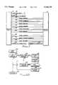
- FIG. 1is a system block diagram of a control device connected to a multiplicity of remote units and telephony over a telephone network;
- FIG. 2is a simplified schematic diagram of a remote unit connected to a power meter, telephone network, and telephone;
- FIG. 3is a diagram illustrating the protocol between the remote units and the control device during data transfer modes
- FIG. 4is a diagram illustrating the protocol between a remote unit, telephone and the control device during a meter reading mode
- FIG. 5is a general flow diagram of a sequence of steps processed by the microcontroller that is shown on FIG. 2;
- FIG. 6Ais a flow diagram of the process steps implementing a detect pulse transition by the microcontroller
- FIG. 6Bis a flow diagram of process steps implementing a stored meter counter executed by the microcontroller
- FIG. 6Cis process steps to determine the time to call for the automatic meter reader implemented by the microcontroller
- FIG. 6Dis process steps to execute an automatic meter reader call by the microcontroller
- FIG. 6Eis process steps implemented by the microcontroller to detect an arming tone
- FIG. 6Fis process steps implemented by the microcontroller to place a call to the control unit
- FIG. 7is flow diagrams of the process data routine implemented by the microcontroller in FIGS. 6E and 6F;
- FIG. 8is a flow diagram of process steps implemented by control device shown in 1.
- FIG. 1there is shown a system diagram 10 of an automatic meter reading system having a control device 12, generally referred to as a headend, connected through telephone line or network 14 and telephone exchange 16 to a plurality of remote units 18a-18n and subscriber telephones 20a-20n.
- a control device 12generally referred to as a headend
- telephone line or network 14and telephone exchange 16
- remote units 18a-18nand subscriber telephones 20a-20n.
- Control device 12includes a Central Processing Unit (CPU) 22 connected to memory device 24, control device transmit/receive 26 also returned to as circuitry and voice processing/call processing circuit 28.
- Call processing circuit 28generates an audio message for distribution onto network 14.
- Circuitry 26includes a modem which preferably complies with Bell standard 202.
- CPU 22computes a power consumption value and generates a power reading request command. This command is fed through the control device circuit 26 to network 14.
- Voice and call processing circuit 28is preferably a Dialogic card manufactured by Dialogic Inc. Modem (not shown) is generally known in the art. One such modem is available from Universal Data Systems of Huntsville, Tenn.
- Circuit 28receives commands and power readings from the remote units 18a-18n and transmits power readings to CPU 22. Circuit 28 also transmits commands and requests to subscribers 20a-n via network 14. Circuit 28 in response to commands from CPU 22 by providing power consumption values to subscriber telephones 20a-20n via a telephone line, herein referred to as network 14.
- CPU 22feeds the resulting power readings to an external device 32 such as a monitor, printer, or other display device.
- the CPU 22communicates with external device 32 via a local network to display information regarding subscriber power consumption or to generate bills which would then be mailed or electronically delivered to the subscribers.
- Each of the remote units 18a-18nare connected to an electric power meter 34a-34n respectively having a rotating interrupter (not shown). These power meters 34a-34n indicate the power being consumed by each of the homes, offices or other facilities of the subscribers facility.
- a preferred meter 34is type Mx available from Landis and Gyr of Lafayette, Ind.
- meters 34a-34neach contain a pulse initiator sensor 36 which detects the rotation of interrupter to indicate energy demand on of the electric power meter 34.
- Sensor 36feeds this energy demand in the form of electric pulse to unit 18.
- Unit 18is shown containing a microcontroller 48 within a transmitter circuit 38 which feeds the detected power readings of sensors 36 onto the network 14.
- Sensor 36is preferably a pulse detector, Model number MCO71 W1 manufactured by Motorola Inc. of Austin, Tex.
- Remote unit 18is preferably built into meter 34, although it maybe external or remotely located from meter 34.
- Remote unit 18is connected to power meter 34 and network 14. Also connected to network 14 is subscriber telephone 20.
- Meter 34contains a sensor 36 connected to remote unit 18.
- Remote unit 18includes an in use detector 20 and a transmitter circuit 38.
- Subscriber telephone 20is operated by a user or subscriber and contains a keypad 42. Keypad 42 is depressed by a subscriber to feed tones onto network 14. Although a telephone 20 is shown to be used by a subscriber in communicating onto a network 14, other devices such as computers, voice-recognition devices, monitors, set-top terminals or home communications devices could be substituted for telephone 20 to communicate through the network 14 to control device 12.
- Transmitter circuit 38includes a microcontroller 48, EEPROM 50, in use detector 40, hook-switch 42 and tone detector 44.
- Microcontroller 48generates tones outputs which are fed onto network 14.
- Tone detector 44contains a high impedance amplifier and signal shaping circuit which signals microcontroller 48 the activity on lines 14.
- Tone generator 46has an active filter which is used to post process tone outputs of Microcontroller 48 and provide the upstream communications between unit 18 and device 12.
- Microcontroller 48communicates with circuit 26 in control device 12 using tone generator 46.
- Hook-switch 42contains a relay which provides a standard telephone off-hook and on-hook indication to network 14.
- Tone detector 44senses tones fed onto network 14 at specific predetermined arming tone frequencies and provides an indication in digital form indicating frequency to microcontroller 48 when those tones are detected.
- the special carrier arming toneshave a predetermined duration and indicate that the control unit 12 is ready to receive commands and data from the remote device 18. These arming tones line a cadence, duration and/or frequency which is not normally carried by the telephone network.
- An in use detector circuit 40determines the network status by sensing the voltage on network 14 to determine whether subscriber 20 is "on-line” or "off-line”. In response to the detection of network status 14 being "on-hook” or "off-hook", in use detector circuit 40 provides the network status indication to microcontroller 48.
- pulse detector 36senses rotation of interrupter on meter 34, and generates electronic pulses in response thereto.
- microcontroller 48sums these pulses and periodically adds the accumulation of pulses to values previously stored in EEPROM 50.
- Microcontroller 48then updates, by replacing the values previously stored, EEPROM 50 with the total accumulated values, herein referred to as read meter values.
- Microcontroller 48may contain a timer (not shown) which provides timing information about when to update the accumulated values. This timer generates an alarming signal to indicate to microcontroller 48 when to send these accumulated read meter values stored in the EEPROM 50 to control device 12.
- Microcontrolleralso responds to requests from device 12 by transmitting these saved accumulated values. Details of the operation is described in FIGS. 3-10.
- Microcontroller 48 in combination with tone generator 46emulate the Bell 202 modem protocol. This emulation is used to communicate with device 26 in control device 12.
- FIG. 3there is shown a diagram illustrating a data transfer protocol (per Bell standard 202) between the remote unit 18 and the control device 12.
- This protocolis invoked when remote unit 18 initiates a transfer of information, i.e. meter reading data, to control device 12.
- remote unit 18checks in line 66 to determine if the network 14 is available for remote unit 18 to transmit information to control device 12. Upon determining that the line is available, remote unit 18 dials the control device 12 at a predetermined telephone number in line 68.
- Control device 12responds to remote unit 18 by raising carrier in line 70, and then issuing a command such as "send data" in line 72. Control device then drops carrier in line 74, and waits for a response from remote unit 18.
- Remote unit 18acknowledges the issued commands by raising carrier in line 76 and issues a response to the commands in line 78 by sending data or indicating that the data was completely sent. A frame check sequence is used for commands and data that insures integrity of the data transfer. Remote unit 18 then drops carrier in line 80. Control unit 12 and remote unit 18 repeat lines 70-80 as often as necessary to transfer all information between remote unit 18 and control device 12.
- Control device in line 82after transferring all information, acknowledges that all information has completely been transferred by raising carrier in line 82, issuing a hang-up command in line 84 and dropping carrier in line 86.
- Both control unit 12 and remote unit 18expect commands to be issued within a certain period of time, and if this timeout period is reached, the call is considered a failure.
- remote unit 18Upon receipt of the hang-up command on line 84, remote unit 18 terminates the connection by generating an on-hook condition on line 88, and simultaneously control device 12 terminates the connection by generating and on-hook condition in line 90.
- the data transfer protocolis preferably half duplex, although other protocol's such as full duplex, or TCP/IP could be used as well to transfer data.
- FIG. 4there is shown a diagram illustrating another communications protocol between the remote unit 18 and the control device 12 via network 14.
- the subscriberuses this protocol on the telephone 20 to initiate communications and obtain information about its meter reading in the remote unit 18.
- the protocolbegins on line 100 with the subscriber dialing the control device 12 with telephone 20.
- the phone number of the remote unit 18a-18n which corresponds to the remote units addressis preferably sent to the control device 12 by the network 14 using a telephone network automatic number indication (ANI).
- ANItelephone network automatic number indication
- Control device 12then answers the call in line 101 and sends an audio instruction to the subscriber on line 102.
- the subscriberlistens to the message on telephone 20 and provides a response by audio, voice or depressing a keypad (not shown) on telephone 20 to send the subscriber commands to control device 12.
- Control device 12continues to listen to the subscriber initiated query and message on line 104. In response thereto device 12 sends more audio commands to the subscriber via telephone 20 on line 102 to indicate to the subscriber to depress certain buttons on the keypad. Although audio commands are the preferred method for transmitting information from the control device 12 to the subscriber, other methods such as video, modems, and facsimiles may be used as well.
- Control device 12in response to the subscriber's commands then issues a series of commands to remote unit 18 to retrieve information for the subscriber.
- the first of these series of commandsis an arming tone (line 106).
- Arming toneis preferably a predetermined fixed frequency carrier recognizable by the remote unit 18.
- Control devicethen issues on line 108 a standard modem carrier signal on network 14.
- Remote unit 18responds to the carrier signal by forcing a network "off-hook" tone on line 110.
- Control device 12responds to the "off-hook" tone by issuing a request command on line 112 and a drop carrier signal.
- Unit 18acknowledges lines 112 and 114 by raising carrier on line 116, issuing a response on line 118 and dropping carrier on line 120. In issuing a response on line 118, unit 18 sends power readings to control device 12. Lines 112-120 are then repeated as necessary to permit unit 18 to transmit all information necessary to control device 12.
- device 12After all data is transferred between unit 18 and device 12, device 12 raises carrier on line 122, issues a hangup command on line 124 and drops carrier on line 126. Remote unit 18 then terminates its connection to network 14 by going on hook in line 128.
- the control device 12 in line 130reports a power consumption value to the remote unit 18 using an audio tone that can be recognized by the subscriber. Control device 12 then terminates its connection by a hang-up command on line 132. The remote unit 18 terminates its connection by hanging up network 44 on line 133.
- microcontroller 48powers up.
- step 122microcontroller 48 initiates internal registers, LEDS, and timers.
- Microcontroller 48restores meter readings in routine 124, which is shown in FIG. 6A. It stores a meter counter in routine 126 (FIG. 6B), then determines a time to call for an automatic meter reading in routine 128(FIG. 6C).
- routine 130FIG. 6D
- microcontroller 48signals transmitter 38 to place a call to control device 12.
- routine 131(FIG. 6E) detects an arming tone and carrier sequence on network 14.
- Remote unit 18places a call to control device 12 in routine 132 (FIG. 6F). After executing routine 132, routines 124-132 are repeated.
- detect pulse transition routine 124where the meter readings are deleted.
- the state of an LED(not shown) within sensor 36 is sensed. This LED indicates the current position of the interrupter on meter 34. This LED alternates back and forth from an "off state” to an "on state” as an interrupter rotates.
- step 134the current LED state is retrieved and a LED flag is set equal to the current LED state. The LED flag is compared against a previous LED flag which is initially set during power on to an "off-state" in step 136. If this LED flag equals the prior LED flag then microcontroller 48 returns to execute step 126.
- microcontroller 48 in step 138determines whether the current LED flag is set to an "on-state", and the prior LED flag was set to an "off-state". When the current LED flag equals an "on-state", microcontroller 48 executes step 140. If the current LED is off, then microcontroller 48 executes step 142 in which the previous LED flag is set to off ending routine 124. In step 140 a meter counter is incremented in RAM within microcontroller 48. The microcontroller 48 then sets the previous LED flag to "on” in step 142 and returns.
- routine 126microcontroller 48 determines in step 146, whether timer 50 has timed out. If timer 50 has timed out, microcontroller 48 executes step 148. If timer 50 has not timed out, routine 126 ends. If timer 50 has timed out, microcontroller 48 executes step 148 and moves the current value of the meter located in RAM into EEProm 50. Microcontroller 48 then resets timer in step 150 and ends routine 126.
- AMR call timeout routine 128in which microcontroller 48 determines whether to place a call to the control device to automatically meter previous reading.
- microcontroller 48determines in step 152 whether a call to control device 12 is already scheduled or pending, and whether a previously placed call has failed. If a call is pending the microcontroller 48 ends sequence 128 and executes sequence 130. If the call is not pending, the microcontroller 48 determines in step 154 whether the automatic meter reading timer 50 has timed-out, thereby indicating it is time to make another call.
- step 156a call pending flag to an "automatic meter reading" (AMR) state, indicating that a call is scheduled to be sent to the control device 12. Subsequent to step 156 or if the automatic meter reading timer 50 has not timed out in step 154, sequence 128 returns and sequence 130 is executed.
- AMRautomatic meter reading
- Sequence 130begins in step 160 by microcontroller 48 checking the call pending flag to see if it is a true state, i.e., equals AMR. If call pending flag equals AMR, microcontroller 48 determines whether retry timers have expired in step 162. If the retry timer has expired or if the recall pending flag equals AMR, then this sequence 128 ends. If the retry timer has expired, microcontroller 48 in step 168 initiates a network call to device 12.
- microcontroller 48places a call to control device 12, and exchanges information including commands.
- Microcontroller 48processes these commands in routine 170 which is described later in FIG. 7.
- Example commandsincludes reading the stored meter readings in the EEProm, reading the meter readings stored in RAM, storing the next time to place a call, programming various phone numbers to call, getting the status of the power meter and the status of power in the home, and hanging up the line.
- microcontroller 48determine in step 171 whether a call was successfully placed. If the call was successful, the call pending flag is cleared, i.e., set to not AMR, in step 172 indicating not to retry the call. If the call was not successful, the microcontroller 48 in step 174 sets its internal retry timer and then ends routine 130.
- routine 131in which microcontroller 48 performs an arming tone and carrier detection.
- This routinebegins in step 162 where the microcontroller 48 determines whether or not an arming tone has been detected on network line 14 by accessing detector 24. If an arming tone is not detected, routine 131 ends. If an arming tone is detected, microcontroller 48 determines whether or not a modem carrier tone has been detected in step 164. If a modem carrier tone is not detected, routine 131 ends, however, if a modem carrier tone is detected, microcontroller 48 executes step 166.
- step 166microcontroller 48 feeds a signal to hook-switch 22 to take network 14 "off-hook". Microcontroller 48 then begins accepting data on network 14 and executes step 168.
- step 168microcontroller 48 determines whether a "hang-up" command is received from network 14. If received, microcontroller 48 returns to end the arming tone detection routine 158. If a "hang-up" command is not received, but another command is received, microcontroller 48 in step 170 processes and receives data. Details of process data step 170 will be explained later in FIG. 7. Microcontroller 48 continues to execute steps 168 and 170 until a "hang-up" command is received. When a "hang-up" command is received, arming tone and carrier detection routine 131 ends.
- routine 132in which microcontroller 48 places a call to the control device 12.
- microcontroller 48determines whether or not the arming tome has been detected from detector 24. If the arming tone has not been detected microcontroller 48 ends routine 132. However, if a call is to be placed then the microcontroller 48 dials control device 12 via network 14.
- microcontroller 48determines in step 176 whether or not a carrier signal is received on network line 14. If a carrier signal is received, microcontroller 48 processes data in routine 170 as described later in FIG. 7. If microcontroller 48 has not received a carrier signal, then microcontroller 48 in step 178 determines whether or not a timeout has occurred in one of its internal timers. If a time-out has not occurred, microcontroller 48 re-executes step 176. However, if a time-out has occurred, a hangup step 182 is executed. After processing data in sequence 170, microcontroller 48 determines whether a "hang-up" has been received from device 12 in step 180.
- microcontroller 48then re-executes the process data routine 170. If a microcontroller 48 received a "hang-up” command was it hangs up network 14 in step 182. Microcontroller 48 in hangup step 182 sends a signal to place phone hook-switch 22 in the "on-hook” position.
- microcontroller 48determines in step 186 whether or not device 12 has issued a command by polling network 14. If device 12 has issued a command, microcontroller 48 executes step 188. If device 12 has not issued a command, the microcontroller 48 continues to poll network 14 until a command is issued. In step 188, the microcontroller 48 raises carrier to acknowledge a command was issued to device 12. Next the microcontroller 48 in step 190 determines if the command from device 12 was a read type command. If it was, microcontroller 48 in step 192 reads the requested data from retry and transmits this data to device 12. Exemplary types of read type commands include provide meter readings value, phone number of subscriber, subscribers home power status.
- step 192data is transmitted to the device 12 by microcontroller 48 using modem 54. If the command in step 190 was not a read type command, microcontroller 48 in step 194 determines if the command was a write type command. If it was, then microcontroller 48 in step 196 stores the write command information in its RAM. An exemplary write command is the date when the next call is to be placed by microcontroller 48 to control device 12.
- microcontroller 48determines in step 198 if the command was a hangup command. If it was not, microcontroller 48 drops carrier in step 200. After microcontroller 48 executes steps 192, 196 or 200, microcontroller 48 checks the next issued command in step 186.
- step 198If the command detected in step 198 was a hangup command, microcontroller 48 goes to an onhook condition in step 201.
- step 201microcontroller 48 feeds a signal to switch 22 to place network 14 on an onhook condition.
- step 201microcontroller 48 sequence 170 ends.
- control device 12receives a call from the remote unit 18 over network 14 and determines whether or not an ANI (Automatic Number Indication) and a DNI (Destination Number Indication) has been received. Then ANI is the phone number or address of the remote unit 18 or subscriber calling. The DNI is the phone number which was called by remote unit 18/subscriber. The ANI and DNI are typically generated by the local phone exchange. The subscriber and/or remote unit 18 may call a different number to signal a different function. For example, the remote device 18 may call phone number 555-1000 when it wants to provide meter reading (i.e.
- the remote unit 18may call 555-1001 when it wants to indicate to the remote device that there was a power outage.
- the subscribermay call a third number, i.e. 555-1002, if it wants to obtain billing information.
- the DNIwill indicate a customer dial tone.
- step 206the headend 12 stores in memory the ANI and DNI number.
- step 210the control device 12 raises the modem tones and then generates the special carrier number tones that was previously discussed.
- a meter read commandis issued onto the network by control device 12 in step 212.
- Remote unit 18then sends the meter readings on to network 14. The readings are stored by control device 12 into memory in step 214.
- the control device 12would then send in step 216 to the remote unit a value indicating next time that the meter reading is to be sent by the remote unit 18.
- the remote unit 18contains an internal clock with a default callback timer. If this next time value corresponding to a predetermined time period (typically 30 days) is not sent, remote unit 18 will automatically dial up the control device 12 within the predetermined period of time.
- the control device 12executes step 204.
- Control device 12 in step 218determines whether or not the DNI equals the customer dial tone. If it does control device 12 executes steps 220-228. If the DNI does not equal the customer dial tone, device 12 re-executes step 204. In step 220 the control device plays and processes the message to the subscriber. An arming tone is issued and carrier is raised in step 222 for the previously discussed purpose. Next step 224 device 12 retrieves and deletes the current meter reading from remote unit 18 with commands using the protocol sequence previously defined.
- step 226the control device 12 gets the last stored reading of the meter and calculates usage, i.e., power consumption values.
- This power consumption valueis calculated by determining the difference between the initial power meter reading and the recently detected power reading. Once the power consumption value is determined, a rate is computed by looking up in a predetermined "look-up" table, the current rates based on total power consumption in a home. A rate table is downloaded into the control device 12 by a utility company. This rate is then multiplied by the difference between the initial power meter reading and the detected power reading to compute a usage.
- step 228, the calculated power consumption and usageis transmitted using the voice processing card 28 to the subscriber.
- routine 202then begins again in step 204.
- Power consumptionis one type of information that may be provided to the subscriber, other types of information may be provided as well.
- Other exemplary information that can be provided to the subscriberinclude weather, time, advertising, news information.
Landscapes
- Engineering & Computer Science (AREA)
- Signal Processing (AREA)
- Telephonic Communication Services (AREA)
- Arrangements For Transmission Of Measured Signals (AREA)
- Selective Calling Equipment (AREA)
Abstract
Description
Claims (18)
Priority Applications (1)
| Application Number | Priority Date | Filing Date | Title |
|---|---|---|---|
| US08/718,752US5764739A (en) | 1995-06-30 | 1996-09-23 | Method and apparatus for providing information to a subscriber over an electronic network |
Applications Claiming Priority (2)
| Application Number | Priority Date | Filing Date | Title |
|---|---|---|---|
| US08/497,503US5559870A (en) | 1995-06-30 | 1995-06-30 | Method and apparatus for providing information to a subscriber over an electronic network |
| US08/718,752US5764739A (en) | 1995-06-30 | 1996-09-23 | Method and apparatus for providing information to a subscriber over an electronic network |
Related Parent Applications (1)
| Application Number | Title | Priority Date | Filing Date |
|---|---|---|---|
| US08/497,503ContinuationUS5559870A (en) | 1995-06-30 | 1995-06-30 | Method and apparatus for providing information to a subscriber over an electronic network |
Publications (1)
| Publication Number | Publication Date |
|---|---|
| US5764739Atrue US5764739A (en) | 1998-06-09 |
Family
ID=23977143
Family Applications (2)
| Application Number | Title | Priority Date | Filing Date |
|---|---|---|---|
| US08/497,503Expired - LifetimeUS5559870A (en) | 1995-06-30 | 1995-06-30 | Method and apparatus for providing information to a subscriber over an electronic network |
| US08/718,752Expired - Fee RelatedUS5764739A (en) | 1995-06-30 | 1996-09-23 | Method and apparatus for providing information to a subscriber over an electronic network |
Family Applications Before (1)
| Application Number | Title | Priority Date | Filing Date |
|---|---|---|---|
| US08/497,503Expired - LifetimeUS5559870A (en) | 1995-06-30 | 1995-06-30 | Method and apparatus for providing information to a subscriber over an electronic network |
Country Status (1)
| Country | Link |
|---|---|
| US (2) | US5559870A (en) |
Cited By (49)
| Publication number | Priority date | Publication date | Assignee | Title |
|---|---|---|---|---|
| US6401081B1 (en)* | 1995-11-20 | 2002-06-04 | Schlumberger Resource Management Services, Inc. | Modular object-based architecture for extensible master station software |
| US20020082748A1 (en)* | 2000-06-15 | 2002-06-27 | Internet Energy Systems, Inc. | Utility monitoring and control systems |
| US6481012B1 (en) | 1999-10-27 | 2002-11-12 | Diva Systems Corporation | Picture-in-picture and multiple video streams using slice-based encoding |
| US20030028879A1 (en)* | 1999-10-27 | 2003-02-06 | Gordon Donald F. | Picture-in-picture and multiple video streams using slice-based encoding |
| US6584153B1 (en) | 1998-07-23 | 2003-06-24 | Diva Systems Corporation | Data structure and methods for providing an interactive program guide |
| US6614843B1 (en) | 1999-04-15 | 2003-09-02 | Diva Systems Corporation | Stream indexing for delivery of interactive program guide |
| EP1260090A4 (en)* | 2000-02-29 | 2003-09-10 | Quadlogic Conrols Corp | System and method for on-line monitoring and billing of power consumption |
| US6621870B1 (en) | 1999-04-15 | 2003-09-16 | Diva Systems Corporation | Method and apparatus for compressing video sequences |
| US20030193405A1 (en)* | 2002-04-15 | 2003-10-16 | Hunt Power, L.P. | User-installable power consumption monitoring system |
| US20040003024A1 (en)* | 2002-06-26 | 2004-01-01 | Jarkko Sairanen | Method, system and computer program product for personalizing the functionality of a personal communication device |
| US20040010446A1 (en)* | 2002-07-08 | 2004-01-15 | Marko Vanska | Mobile customer relationship management |
| US20040025178A1 (en)* | 1998-07-23 | 2004-02-05 | Gordon Donald F. | Interactive user interface |
| US6704359B1 (en) | 1999-04-15 | 2004-03-09 | Diva Systems Corp. | Efficient encoding algorithms for delivery of server-centric interactive program guide |
| US20040087273A1 (en)* | 2002-10-31 | 2004-05-06 | Nokia Corporation | Method and system for selecting data items for service requests |
| US20040093274A1 (en)* | 2002-11-08 | 2004-05-13 | Marko Vanska | Method and apparatus for making daily shopping easier |
| US20040111340A1 (en)* | 1999-09-03 | 2004-06-10 | Reel Greg T. | Method and system for procuring, storing and distributing remotely accessed data gathered by logging devices |
| US6754905B2 (en) | 1998-07-23 | 2004-06-22 | Diva Systems Corporation | Data structure and methods for providing an interactive program guide |
| US20040210931A1 (en)* | 1998-11-30 | 2004-10-21 | Gordon Donald F | Service provider side interactive program guide encoder |
| US20050034155A1 (en)* | 1999-10-27 | 2005-02-10 | Gordon Donald F. | Apparatus and method for combining realtime and non-realtime encoded content |
| US6904610B1 (en) | 1999-04-15 | 2005-06-07 | Sedna Patent Services, Llc | Server-centric customized interactive program guide in an interactive television environment |
| US20050125745A1 (en)* | 2003-12-08 | 2005-06-09 | Jyri Engestrom | Apparatus, system, method and computer program product for creating shortcuts to functions in a personal communication device |
| US6934965B2 (en) | 1998-07-23 | 2005-08-23 | Sedna Patent Services, Llc | System for generating, distributing and receiving an interactive user interface |
| US6947854B2 (en) | 2000-02-29 | 2005-09-20 | Quadlogic Controls Corporation | System and method for on-line monitoring and billing of power consumption |
| US20050222918A1 (en)* | 2002-11-01 | 2005-10-06 | Marko Vanska | Disposable mini-applications |
| FR2870421A1 (en)* | 2004-05-17 | 2005-11-18 | Alain Torregrossa | SYSTEM FOR REMOTELY REPORTING A COUNTING STATE OF A CONSUMPTION OF FLUID OR ENERGY |
| US6968567B1 (en) | 1999-04-15 | 2005-11-22 | Sedna Patent Services, Llc | Latency reduction in providing interactive program guide |
| US20060002610A1 (en)* | 2004-07-02 | 2006-01-05 | Hartti Suomela | Initiation of actions with compressed action language representations |
| US20060058011A1 (en)* | 2002-06-17 | 2006-03-16 | Marko Vanska | Method and device for storing and accessing personal information |
| US7058965B1 (en) | 1999-04-15 | 2006-06-06 | Sedna Patent Services, Llc | Multiplexing structures for delivery of interactive program guide |
| US7091968B1 (en) | 1998-07-23 | 2006-08-15 | Sedna Patent Services, Llc | Method and apparatus for encoding a user interface |
| US20060184979A1 (en)* | 1999-06-28 | 2006-08-17 | Sedna Patent Services, Llc | System and method for delivery of short-time duration video segments |
| US7127737B1 (en) | 2000-01-26 | 2006-10-24 | Sedna Patent Services, Llc | Bandwidth management techniques for delivery of interactive program guide |
| US7254824B1 (en) | 1999-04-15 | 2007-08-07 | Sedna Patent Services, Llc | Encoding optimization techniques for encoding program grid section of server-centric interactive programming guide |
| US20070234096A1 (en)* | 2004-06-04 | 2007-10-04 | Bryan Chase | Method and system for monitoring module power status in a communication device |
| US7373652B1 (en) | 1999-07-22 | 2008-05-13 | Sedna Patent Services, Llc | Server-centric search function in an interactive program guide |
| US20080139120A1 (en)* | 2004-06-04 | 2008-06-12 | Bryan Chase | Method and system for monitoring module power information in a communication device |
| US7464394B1 (en) | 1999-07-22 | 2008-12-09 | Sedna Patent Services, Llc | Music interface for media-rich interactive program guide |
| US7486782B1 (en)* | 1997-09-17 | 2009-02-03 | Roos Charles E | Multifunction data port providing an interface between a digital network and electronics in residential or commercial structures |
| US7607152B1 (en) | 2000-01-26 | 2009-10-20 | Cox Communications, Inc. | Demand-cast system and bandwidth management for delivery of interactive programming |
| US7752321B1 (en) | 2003-12-29 | 2010-07-06 | Aol Inc. | Validating user experience type settings |
| US8452555B2 (en) | 2001-02-28 | 2013-05-28 | Quadlogic Controls Corporation | Apparatus and methods for multi-channel metering |
| US9042446B2 (en) | 1999-04-15 | 2015-05-26 | Comcast Ip Holdings I, Llc | Temporal slice persistence method and apparatus for delivery of interactive program guide |
| US9094727B1 (en) | 1999-10-27 | 2015-07-28 | Cox Communications, Inc. | Multi-functional user interface using slice-based encoding |
| US9154813B2 (en) | 2011-06-09 | 2015-10-06 | Comcast Cable Communications, Llc | Multiple video content in a composite video stream |
| US9286294B2 (en) | 1992-12-09 | 2016-03-15 | Comcast Ip Holdings I, Llc | Video and digital multimedia aggregator content suggestion engine |
| US9813641B2 (en) | 2000-06-19 | 2017-11-07 | Comcast Ip Holdings I, Llc | Method and apparatus for targeting of interactive virtual objects |
| US9924234B2 (en) | 1998-07-23 | 2018-03-20 | Comcast Ip Holdings I, Llc | Data structure and methods for providing an interactive program |
| US10140433B2 (en) | 2001-08-03 | 2018-11-27 | Comcast Ip Holdings I, Llc | Video and digital multimedia aggregator |
| US10349096B2 (en) | 2001-08-03 | 2019-07-09 | Comcast Ip Holdings I, Llc | Video and digital multimedia aggregator content coding and formatting |
Families Citing this family (45)
| Publication number | Priority date | Publication date | Assignee | Title |
|---|---|---|---|---|
| US5559870A (en)* | 1995-06-30 | 1996-09-24 | Scientific-Atlanta, Inc. | Method and apparatus for providing information to a subscriber over an electronic network |
| US5896382A (en)* | 1996-11-19 | 1999-04-20 | Scientific-Atlanta, Inc. | Method and apparatus for communicating information between a headend and subscriber over a wide area network |
| US7046682B2 (en) | 1997-02-12 | 2006-05-16 | Elster Electricity, Llc. | Network-enabled, extensible metering system |
| AR011440A1 (en) | 1997-02-12 | 2000-08-16 | Abb Power T & D Co | ELECTRONIC MEASUREMENT PROVISION |
| US6124806A (en) | 1997-09-12 | 2000-09-26 | Williams Wireless, Inc. | Wide area remote telemetry |
| US6100816A (en)* | 1998-01-16 | 2000-08-08 | Cellnet Data Systems, Inc. | Utility meter adapter |
| US6700902B1 (en) | 1998-10-19 | 2004-03-02 | Elster Electricity, Llc | Method and system for improving wireless data packet delivery |
| US7061398B2 (en)* | 1999-08-16 | 2006-06-13 | Bs&B Safety Systems Limited | Two-way wide area telemetry |
| US7197330B1 (en) | 2000-03-14 | 2007-03-27 | Intel Corporation | Dual port wireless modem for circuit switched and packet switched data transfer |
| US6820049B1 (en) | 1999-09-20 | 2004-11-16 | Intel Corporation | Data collection system |
| GB2370185B (en)* | 1999-09-20 | 2003-11-19 | Xircom Wireless Inc | Communications bridge for circuit switched data transfer simulation |
| US6697421B1 (en) | 1999-11-19 | 2004-02-24 | Intel Corporation | Operator independent, transparent wireless modem management |
| US6363335B1 (en)* | 1999-09-20 | 2002-03-26 | Xircom Wireless, Inc. | Communications bridge for circuit switched data transfer simulation |
| US6816480B1 (en) | 1999-09-20 | 2004-11-09 | Intel Corporation | Data terminal apparatus |
| US6598003B1 (en) | 2000-10-31 | 2003-07-22 | Rx Monitoring Services, Llc | Power and environmental condition monitoring system and method |
| US6867707B1 (en) | 2002-04-24 | 2005-03-15 | Elster Electricity, Llc | Automated on-site meter registration confirmation using a portable, wireless computing device |
| US7119713B2 (en) | 2002-06-27 | 2006-10-10 | Elster Electricity, Llc | Dynamic self-configuring metering network |
| US20040113810A1 (en) | 2002-06-28 | 2004-06-17 | Mason Robert T. | Data collector for an automated meter reading system |
| US7227350B2 (en) | 2004-03-18 | 2007-06-05 | Elster Electricity, Llc | Bias technique for electric utility meter |
| US7315162B2 (en) | 2004-03-18 | 2008-01-01 | Elster Electricity, Llc | Reducing power consumption of electrical meters |
| US7262709B2 (en) | 2004-04-26 | 2007-08-28 | Elster Electricity, Llc | System and method for efficient configuration in a fixed network automated meter reading system |
| US7239250B2 (en) | 2004-04-26 | 2007-07-03 | Elster Electricity, Llc | System and method for improved transmission of meter data |
| US7187906B2 (en) | 2004-04-26 | 2007-03-06 | Elster Electricity, Llc | Method and system for configurable qualification and registration in a fixed network automated meter reading system |
| US7142106B2 (en) | 2004-06-15 | 2006-11-28 | Elster Electricity, Llc | System and method of visualizing network layout and performance characteristics in a wireless network |
| US7742430B2 (en) | 2004-09-24 | 2010-06-22 | Elster Electricity, Llc | System for automated management of spontaneous node migration in a distributed fixed wireless network |
| US7702594B2 (en) | 2004-09-24 | 2010-04-20 | Elster Electricity, Llc | System and method for automated configuration of meters |
| US7170425B2 (en) | 2004-09-24 | 2007-01-30 | Elster Electricity, Llc | System and method for creating multiple operating territories within a meter reading system |
| US7176807B2 (en) | 2004-09-24 | 2007-02-13 | Elster Electricity, Llc | System for automatically enforcing a demand reset in a fixed network of electricity meters |
| US9379907B2 (en)* | 2004-10-20 | 2016-06-28 | Electro Industries/Gauge Tech | Multichannel intelligent electronic device with advanced communication capabilities |
| US7327998B2 (en) | 2004-12-22 | 2008-02-05 | Elster Electricity, Llc | System and method of providing a geographic view of nodes in a wireless network |
| US7308370B2 (en) | 2005-03-22 | 2007-12-11 | Elster Electricity Llc | Using a fixed network wireless data collection system to improve utility responsiveness to power outages |
| US7495578B2 (en) | 2005-09-02 | 2009-02-24 | Elster Electricity, Llc | Multipurpose interface for an automated meter reading device |
| US7308369B2 (en) | 2005-09-28 | 2007-12-11 | Elster Electricity Llc | Ensuring automatic season change demand resets in a mesh type network of telemetry devices |
| US7769149B2 (en)* | 2006-01-09 | 2010-08-03 | Current Communications Services, Llc | Automated utility data services system and method |
| US7427927B2 (en) | 2006-02-16 | 2008-09-23 | Elster Electricity, Llc | In-home display communicates with a fixed network meter reading system |
| US7545285B2 (en) | 2006-02-16 | 2009-06-09 | Elster Electricity, Llc | Load control unit in communication with a fixed network meter reading system |
| US8073384B2 (en) | 2006-12-14 | 2011-12-06 | Elster Electricity, Llc | Optimization of redundancy and throughput in an automated meter data collection system using a wireless network |
| US8320302B2 (en) | 2007-04-20 | 2012-11-27 | Elster Electricity, Llc | Over the air microcontroller flash memory updates |
| JP5130368B2 (en)* | 2007-09-04 | 2013-01-30 | シーメンス エンタープライズ コミュニケーションズ ゲゼルシャフト ミット ベシュレンクテル ハフツング ウント コンパニー コマンディートゲゼルシャフト | Method and communication terminal device for detecting the state of a telephone handset |
| WO2009082761A1 (en) | 2007-12-26 | 2009-07-02 | Elster Electricity, Llc. | Optimized data collection in a wireless fixed network metering system |
| US8525692B2 (en) | 2008-06-13 | 2013-09-03 | Elster Solutions, Llc | Techniques for limiting demand from an electricity meter with an installed relay |
| US8203463B2 (en) | 2009-02-13 | 2012-06-19 | Elster Electricity Llc | Wakeup and interrogation of meter-reading devices using licensed narrowband and unlicensed wideband radio communication |
| WO2012102727A1 (en)* | 2011-01-28 | 2012-08-02 | Hewlett-Packard Development Company, L. P. | Distributing information |
| US11516899B2 (en) | 2015-05-27 | 2022-11-29 | Electro Industries/Gauge Tech | Devices, systems and methods for electrical utility submetering |
| CN110177131B (en)* | 2019-04-26 | 2020-06-26 | 特斯联(北京)科技有限公司 | Electricity consumption statistical query method based on Internet of things |
Citations (4)
| Publication number | Priority date | Publication date | Assignee | Title |
|---|---|---|---|---|
| US5142566A (en)* | 1988-03-31 | 1992-08-25 | Industria Grafica Meschi Srl. | Method for transmitting billing data and invoices |
| US5225997A (en)* | 1990-06-05 | 1993-07-06 | Sygnus Controls Inc. | Automatic monitoring and remote reporting device |
| US5408523A (en)* | 1992-06-22 | 1995-04-18 | Basic Measuring Instruments, Inc. | Electronic remote data recorder with facsimile output for utility AC power systems |
| US5559870A (en)* | 1995-06-30 | 1996-09-24 | Scientific-Atlanta, Inc. | Method and apparatus for providing information to a subscriber over an electronic network |
- 1995
- 1995-06-30USUS08/497,503patent/US5559870A/ennot_activeExpired - Lifetime
- 1996
- 1996-09-23USUS08/718,752patent/US5764739A/ennot_activeExpired - Fee Related
Patent Citations (4)
| Publication number | Priority date | Publication date | Assignee | Title |
|---|---|---|---|---|
| US5142566A (en)* | 1988-03-31 | 1992-08-25 | Industria Grafica Meschi Srl. | Method for transmitting billing data and invoices |
| US5225997A (en)* | 1990-06-05 | 1993-07-06 | Sygnus Controls Inc. | Automatic monitoring and remote reporting device |
| US5408523A (en)* | 1992-06-22 | 1995-04-18 | Basic Measuring Instruments, Inc. | Electronic remote data recorder with facsimile output for utility AC power systems |
| US5559870A (en)* | 1995-06-30 | 1996-09-24 | Scientific-Atlanta, Inc. | Method and apparatus for providing information to a subscriber over an electronic network |
Cited By (100)
| Publication number | Priority date | Publication date | Assignee | Title |
|---|---|---|---|---|
| US9286294B2 (en) | 1992-12-09 | 2016-03-15 | Comcast Ip Holdings I, Llc | Video and digital multimedia aggregator content suggestion engine |
| US6401081B1 (en)* | 1995-11-20 | 2002-06-04 | Schlumberger Resource Management Services, Inc. | Modular object-based architecture for extensible master station software |
| US7486782B1 (en)* | 1997-09-17 | 2009-02-03 | Roos Charles E | Multifunction data port providing an interface between a digital network and electronics in residential or commercial structures |
| US8739218B2 (en) | 1998-07-23 | 2014-05-27 | Comcast Ip Holdings I, Llc | Data structure and methods for providing an interactive program guide |
| US20040133910A1 (en)* | 1998-07-23 | 2004-07-08 | Gordon Donald F. | Data structure and methods for providing an interactive program guide |
| US7091968B1 (en) | 1998-07-23 | 2006-08-15 | Sedna Patent Services, Llc | Method and apparatus for encoding a user interface |
| US20060253868A1 (en)* | 1998-07-23 | 2006-11-09 | Sedna Patent Services, Llc | Method and apparatus for encoding a user interface |
| US6934965B2 (en) | 1998-07-23 | 2005-08-23 | Sedna Patent Services, Llc | System for generating, distributing and receiving an interactive user interface |
| US9924234B2 (en) | 1998-07-23 | 2018-03-20 | Comcast Ip Holdings I, Llc | Data structure and methods for providing an interactive program |
| US9674586B2 (en) | 1998-07-23 | 2017-06-06 | Comcast Ip Holdings I, Llc | Data structure and methods for providing an interactive program guide |
| US6754905B2 (en) | 1998-07-23 | 2004-06-22 | Diva Systems Corporation | Data structure and methods for providing an interactive program guide |
| US8522277B2 (en) | 1998-07-23 | 2013-08-27 | Comcast Ip Holdings I, Llc | Interactive user interface |
| US20040025178A1 (en)* | 1998-07-23 | 2004-02-05 | Gordon Donald F. | Interactive user interface |
| US6584153B1 (en) | 1998-07-23 | 2003-06-24 | Diva Systems Corporation | Data structure and methods for providing an interactive program guide |
| US7836467B2 (en) | 1998-07-23 | 2010-11-16 | Comcast Ip Holdings I, Llc | Interactive user interface |
| US7634788B2 (en) | 1998-11-30 | 2009-12-15 | Comcast Ip Holdings I, Llc | Service provider side interactive program guide encoder |
| US20040210931A1 (en)* | 1998-11-30 | 2004-10-21 | Gordon Donald F | Service provider side interactive program guide encoder |
| US8578419B2 (en) | 1999-04-15 | 2013-11-05 | Comcast Ip Holdings I, Llc | Server-centric customized interactive program guide in an interactive television environment |
| US20050155063A1 (en)* | 1999-04-15 | 2005-07-14 | Sedna Patent Services, Llc | Server-centric customized interactive program guide in an interactive television environment |
| US6704359B1 (en) | 1999-04-15 | 2004-03-09 | Diva Systems Corp. | Efficient encoding algorithms for delivery of server-centric interactive program guide |
| US7058965B1 (en) | 1999-04-15 | 2006-06-06 | Sedna Patent Services, Llc | Multiplexing structures for delivery of interactive program guide |
| US7953160B2 (en) | 1999-04-15 | 2011-05-31 | Comcast Ip Holdings I, Llc | Method and apparatus for compressing video sequences |
| US20040086040A1 (en)* | 1999-04-15 | 2004-05-06 | Sadik Bayrakeri | Efficient encoding algorithms for delivery of server-centric interactive program guide |
| US20090175355A1 (en)* | 1999-04-15 | 2009-07-09 | Comcast Ip Holdings I, Llc | Method and Apparatus for Compressing Video Sequences |
| US6614843B1 (en) | 1999-04-15 | 2003-09-02 | Diva Systems Corporation | Stream indexing for delivery of interactive program guide |
| US7505519B2 (en) | 1999-04-15 | 2009-03-17 | Comcast Ip Holdings, I, Llc | Method and apparatus for compressing video sequences |
| US9456241B2 (en) | 1999-04-15 | 2016-09-27 | Comcast Ip Holdings I, Llc | Server-centric customized interactive program guide in an interactive television environment |
| US9042446B2 (en) | 1999-04-15 | 2015-05-26 | Comcast Ip Holdings I, Llc | Temporal slice persistence method and apparatus for delivery of interactive program guide |
| US20040047417A1 (en)* | 1999-04-15 | 2004-03-11 | Gordon Donald F. | Method and apparatus for compressing video sequences |
| US6621870B1 (en) | 1999-04-15 | 2003-09-16 | Diva Systems Corporation | Method and apparatus for compressing video sequences |
| US6904610B1 (en) | 1999-04-15 | 2005-06-07 | Sedna Patent Services, Llc | Server-centric customized interactive program guide in an interactive television environment |
| US7433406B2 (en) | 1999-04-15 | 2008-10-07 | Sedna Patent Services, Llc | Efficient encoding algorithms for delivery of server-centric interactive program guide |
| US7254824B1 (en) | 1999-04-15 | 2007-08-07 | Sedna Patent Services, Llc | Encoding optimization techniques for encoding program grid section of server-centric interactive programming guide |
| US6968567B1 (en) | 1999-04-15 | 2005-11-22 | Sedna Patent Services, Llc | Latency reduction in providing interactive program guide |
| US20060184979A1 (en)* | 1999-06-28 | 2006-08-17 | Sedna Patent Services, Llc | System and method for delivery of short-time duration video segments |
| US8255956B2 (en) | 1999-06-28 | 2012-08-28 | Cox Communications, Inc. | System and method for delivery of short-time duration video segments |
| US7373652B1 (en) | 1999-07-22 | 2008-05-13 | Sedna Patent Services, Llc | Server-centric search function in an interactive program guide |
| US7464394B1 (en) | 1999-07-22 | 2008-12-09 | Sedna Patent Services, Llc | Music interface for media-rich interactive program guide |
| US6873936B2 (en) | 1999-09-03 | 2005-03-29 | Marathon Products, Inc. | Method and system for procuring, storing and distributing remotely accessed data gathered by logging devices |
| US20040111340A1 (en)* | 1999-09-03 | 2004-06-10 | Reel Greg T. | Method and system for procuring, storing and distributing remotely accessed data gathered by logging devices |
| US20040167837A1 (en)* | 1999-09-03 | 2004-08-26 | Reel Greg T. | Method and system for procuring, storing and distributing remotely accessed data gathered by logging devices |
| US9264711B2 (en) | 1999-10-27 | 2016-02-16 | Comcast Ip Holdings I, Llc | Apparatus and method for combining realtime and non-realtime encoded content |
| US6481012B1 (en) | 1999-10-27 | 2002-11-12 | Diva Systems Corporation | Picture-in-picture and multiple video streams using slice-based encoding |
| US8032906B2 (en) | 1999-10-27 | 2011-10-04 | Comcast Ip Holdings I, Llc | Method and system for providing a program guide and multiple video streams using slice-based encoding |
| US8930998B2 (en) | 1999-10-27 | 2015-01-06 | Comcast Ip Holdings I, Llc | Method and system for providing a program guide and multiple video streams using slice-based encoding |
| US7096487B1 (en) | 1999-10-27 | 2006-08-22 | Sedna Patent Services, Llc | Apparatus and method for combining realtime and non-realtime encoded content |
| US9094727B1 (en) | 1999-10-27 | 2015-07-28 | Cox Communications, Inc. | Multi-functional user interface using slice-based encoding |
| US20040261104A1 (en)* | 1999-10-27 | 2004-12-23 | Gordon Donald F. | Method and apparatus for transmitting video and graphics in a compressed form |
| US20050034155A1 (en)* | 1999-10-27 | 2005-02-10 | Gordon Donald F. | Apparatus and method for combining realtime and non-realtime encoded content |
| US8661465B2 (en) | 1999-10-27 | 2014-02-25 | Comcast Ip Holdings I, Llc | Apparatus and method for combining realtime and non-realtime encoded content |
| US7810116B2 (en) | 1999-10-27 | 2010-10-05 | Comcast Ip Holdings I, Llc | Apparatus and method for combining realtime and non-realtime encoded content |
| US6651252B1 (en) | 1999-10-27 | 2003-11-18 | Diva Systems Corporation | Method and apparatus for transmitting video and graphics in a compressed form |
| US20030028879A1 (en)* | 1999-10-27 | 2003-02-06 | Gordon Donald F. | Picture-in-picture and multiple video streams using slice-based encoding |
| US7380261B2 (en) | 1999-10-27 | 2008-05-27 | Sedna Patent Services, Llc | Method and apparatus for transmitting video and graphics in a compressed form |
| US7127737B1 (en) | 2000-01-26 | 2006-10-24 | Sedna Patent Services, Llc | Bandwidth management techniques for delivery of interactive program guide |
| US7607152B1 (en) | 2000-01-26 | 2009-10-20 | Cox Communications, Inc. | Demand-cast system and bandwidth management for delivery of interactive programming |
| EP1260090A4 (en)* | 2000-02-29 | 2003-09-10 | Quadlogic Conrols Corp | System and method for on-line monitoring and billing of power consumption |
| US6947854B2 (en) | 2000-02-29 | 2005-09-20 | Quadlogic Controls Corporation | System and method for on-line monitoring and billing of power consumption |
| US20020082748A1 (en)* | 2000-06-15 | 2002-06-27 | Internet Energy Systems, Inc. | Utility monitoring and control systems |
| US9813641B2 (en) | 2000-06-19 | 2017-11-07 | Comcast Ip Holdings I, Llc | Method and apparatus for targeting of interactive virtual objects |
| US8452555B2 (en) | 2001-02-28 | 2013-05-28 | Quadlogic Controls Corporation | Apparatus and methods for multi-channel metering |
| US10140433B2 (en) | 2001-08-03 | 2018-11-27 | Comcast Ip Holdings I, Llc | Video and digital multimedia aggregator |
| US10349096B2 (en) | 2001-08-03 | 2019-07-09 | Comcast Ip Holdings I, Llc | Video and digital multimedia aggregator content coding and formatting |
| US20030193405A1 (en)* | 2002-04-15 | 2003-10-16 | Hunt Power, L.P. | User-installable power consumption monitoring system |
| US7049976B2 (en) | 2002-04-15 | 2006-05-23 | Hunt Power, L.P. | User-installable power consumption monitoring system |
| US20060103549A1 (en)* | 2002-04-15 | 2006-05-18 | Hunt Power, L.P. | User-installable power consumption monitoring system |
| US8170615B2 (en) | 2002-06-17 | 2012-05-01 | Nokia Corporation | Method and device for storing and accessing personal information |
| US7450966B2 (en) | 2002-06-17 | 2008-11-11 | Nokia Corporation | Method and device for storing and accessing personal information |
| US7047041B2 (en) | 2002-06-17 | 2006-05-16 | Nokia Corporation | Method and device for storing and accessing personal information |
| US20070191058A1 (en)* | 2002-06-17 | 2007-08-16 | Nokia Corporation | A method and device for storing and accessing personal information |
| US20060058011A1 (en)* | 2002-06-17 | 2006-03-16 | Marko Vanska | Method and device for storing and accessing personal information |
| US7107009B2 (en) | 2002-06-26 | 2006-09-12 | Nokia Corporation | Method, system and computer program product for personalizing the functionality of a personal communication device |
| US20040003024A1 (en)* | 2002-06-26 | 2004-01-01 | Jarkko Sairanen | Method, system and computer program product for personalizing the functionality of a personal communication device |
| US20040010446A1 (en)* | 2002-07-08 | 2004-01-15 | Marko Vanska | Mobile customer relationship management |
| US7606533B2 (en) | 2002-10-31 | 2009-10-20 | Nokia Corporation | Method and system for selecting data items for service requests |
| US20040087273A1 (en)* | 2002-10-31 | 2004-05-06 | Nokia Corporation | Method and system for selecting data items for service requests |
| US20060128408A1 (en)* | 2002-10-31 | 2006-06-15 | Marko Perttila | Method and system for selecting data items for service requests |
| US20050222918A1 (en)* | 2002-11-01 | 2005-10-06 | Marko Vanska | Disposable mini-applications |
| US7130622B2 (en) | 2002-11-01 | 2006-10-31 | Nokia Corporation | Disposable mini-applications |
| US7072672B1 (en) | 2002-11-01 | 2006-07-04 | Nokia Corporation | Disposable mini-applications |
| US20040093274A1 (en)* | 2002-11-08 | 2004-05-13 | Marko Vanska | Method and apparatus for making daily shopping easier |
| US7407107B2 (en) | 2003-12-08 | 2008-08-05 | Nokia Corporation | Apparatus, system, method and computer program product for creating shortcuts to functions in a personal communication device |
| US20050125745A1 (en)* | 2003-12-08 | 2005-06-09 | Jyri Engestrom | Apparatus, system, method and computer program product for creating shortcuts to functions in a personal communication device |
| US8713178B2 (en) | 2003-12-29 | 2014-04-29 | Facebook, Inc. | Tiered cost model for access to a computer network |
| US20100257083A1 (en)* | 2003-12-29 | 2010-10-07 | Aol Llc | Tiered access to a computer network |
| US8396991B2 (en) | 2003-12-29 | 2013-03-12 | Facebook, Inc. | Validating user experience type settings |
| US7752321B1 (en) | 2003-12-29 | 2010-07-06 | Aol Inc. | Validating user experience type settings |
| WO2005114974A1 (en)* | 2004-05-17 | 2005-12-01 | Alain Torregrossa | System for remotely taking a reading from a fluid or energy consumption meter |
| FR2870421A1 (en)* | 2004-05-17 | 2005-11-18 | Alain Torregrossa | SYSTEM FOR REMOTELY REPORTING A COUNTING STATE OF A CONSUMPTION OF FLUID OR ENERGY |
| US20110066867A1 (en)* | 2004-06-04 | 2011-03-17 | Bryan Chase | Method and system for monitoring module power information in a communication device |
| US9146275B2 (en) | 2004-06-04 | 2015-09-29 | Broadcom Corporation | Method and system for monitoring module power information in a communication device |
| US7836315B2 (en)* | 2004-06-04 | 2010-11-16 | Broadcom Corp. | Method and system for monitoring module power information in a communication device |
| US8707065B2 (en) | 2004-06-04 | 2014-04-22 | Broadcom Corporation | Method and system for monitoring module power status in a communication device |
| US20080139120A1 (en)* | 2004-06-04 | 2008-06-12 | Bryan Chase | Method and system for monitoring module power information in a communication device |
| US20110202779A1 (en)* | 2004-06-04 | 2011-08-18 | Bryan Chase | Method and system for monitoring module power status in a communication device |
| US20070234096A1 (en)* | 2004-06-04 | 2007-10-04 | Bryan Chase | Method and system for monitoring module power status in a communication device |
| US8799683B2 (en) | 2004-06-04 | 2014-08-05 | Broadcom Corporation | Method and system for monitoring module power status in a communication device |
| US7304585B2 (en) | 2004-07-02 | 2007-12-04 | Nokia Corporation | Initiation of actions with compressed action language representations |
| US20060002610A1 (en)* | 2004-07-02 | 2006-01-05 | Hartti Suomela | Initiation of actions with compressed action language representations |
| US9154813B2 (en) | 2011-06-09 | 2015-10-06 | Comcast Cable Communications, Llc | Multiple video content in a composite video stream |
Also Published As
| Publication number | Publication date |
|---|---|
| US5559870A (en) | 1996-09-24 |
Similar Documents
| Publication | Publication Date | Title |
|---|---|---|
| US5764739A (en) | Method and apparatus for providing information to a subscriber over an electronic network | |
| EP0527072B1 (en) | Telephone dial-inbound data acquisition system with demand reading capability | |
| US4104486A (en) | System for accumulating data over nondedicated telephone lines | |
| US4126762A (en) | Method and system for accumulating data over nondedicated telephone lines | |
| US5410590A (en) | Monitoring system for remote devices | |
| US5065427A (en) | Fax/data call receiving system and method | |
| US5031209A (en) | Automatic meter reader with microcomputer control system | |
| US6115456A (en) | Remote control system | |
| KR100392861B1 (en) | Modem with automatic callback facility | |
| GB2245456A (en) | Automatic meter reading system with multitasking control | |
| JPH08511666A (en) | Dial-inbound meter interface unit that draws power from the telephone line | |
| US5651057A (en) | Method of communicating data from remote devices to a central computer via a telecommunications link | |
| US5065426A (en) | Facsimile/telephone controller | |
| US5862469A (en) | Method and apparatus for transmitting metering pulse information to a wireless public call office | |
| JP3173307B2 (en) | Gas metering system | |
| KR19990085324A (en) | Remote meter reading system using integrated information and communication terminal and its control method | |
| EP0845896A1 (en) | Remote data access by telephone | |
| KR0143466B1 (en) | Remote coin computating method for payphone | |
| EP1058995A1 (en) | A vending machine audit module system | |
| JP4397106B2 (en) | Remote management system | |
| JP3050893B2 (en) | Network controller | |
| TWI269186B (en) | Complex communications management system and method | |
| TW417375B (en) | Intelligent telephone network for providing information and service | |
| JP3921283B2 (en) | Public service facsimile system | |
| JP2003069745A (en) | System and method for transmitting toll-charging signal |
Legal Events
| Date | Code | Title | Description |
|---|---|---|---|
| AS | Assignment | Owner name:COMVERGE TECHNOLOGIES, INC., NEW JERSEY Free format text:ASSIGNMENT OF ASSIGNORS INTEREST;ASSIGNOR:SCIENTIFIC-ATLANTA, INC.;REEL/FRAME:010360/0525 Effective date:19990830 | |
| REMI | Maintenance fee reminder mailed | ||
| LAPS | Lapse for failure to pay maintenance fees | ||
| STCH | Information on status: patent discontinuation | Free format text:PATENT EXPIRED DUE TO NONPAYMENT OF MAINTENANCE FEES UNDER 37 CFR 1.362 | |
| FP | Lapsed due to failure to pay maintenance fee | Effective date:20020609 | |
| AS | Assignment | Owner name:SILICON VALLEY BANK, CALIFORNIA Free format text:SECURITY INTEREST;ASSIGNOR:COMVERGE, INC.;REEL/FRAME:014033/0330 Effective date:20030407 | |
| FEPP | Fee payment procedure | Free format text:PETITION RELATED TO MAINTENANCE FEES FILED (ORIGINAL EVENT CODE: PMFP); ENTITY STATUS OF PATENT OWNER: LARGE ENTITY | |
| AS | Assignment | Owner name:PARTNERS FOR GROWTH, L.P., CALIFORNIA Free format text:SECURITY AGREEMENT;ASSIGNOR:COMVERGE, INC.;REEL/FRAME:016116/0063 Effective date:20050609 | |
| FEPP | Fee payment procedure | Free format text:PAYOR NUMBER ASSIGNED (ORIGINAL EVENT CODE: ASPN); ENTITY STATUS OF PATENT OWNER: LARGE ENTITY | |
| AS | Assignment | Owner name:COMVERGE, INC., GEORGIA Free format text:RELEASE BY SECURED PARTY;ASSIGNOR:PARTNERS FOR GROWTH, L.P.;REEL/FRAME:020690/0001 Effective date:20080320 | |
| AS | Assignment | Owner name:COMVERGE, INC., GEORGIA Free format text:RELEASE BY SECURED PARTY (2003 FILING);ASSIGNOR:SILICON VALLEY BANK;REEL/FRAME:029382/0796 Effective date:20121127 |