US5764195A - UHF/VHF multifunction ocean antenna system - Google Patents
UHF/VHF multifunction ocean antenna systemDownload PDFInfo
- Publication number
- US5764195A US5764195AUS08/685,812US68581296AUS5764195AUS 5764195 AUS5764195 AUS 5764195AUS 68581296 AUS68581296 AUS 68581296AUS 5764195 AUS5764195 AUS 5764195A
- Authority
- US
- United States
- Prior art keywords
- vhf
- uhf
- radiating elements
- nominally
- antenna system
- Prior art date
- Legal status (The legal status is an assumption and is not a legal conclusion. Google has not performed a legal analysis and makes no representation as to the accuracy of the status listed.)
- Expired - Fee Related
Links
- 230000008878couplingEffects0.000claimsabstractdescription30
- 238000010168coupling processMethods0.000claimsabstractdescription30
- 238000005859coupling reactionMethods0.000claimsabstractdescription30
- XLYOFNOQVPJJNP-UHFFFAOYSA-NwaterSubstancesOXLYOFNOQVPJJNP-UHFFFAOYSA-N0.000claimsabstractdescription9
- 230000005404monopoleEffects0.000claimsabstractdescription8
- 238000005188flotationMethods0.000claimsabstractdescription7
- 238000000926separation methodMethods0.000claimsdescription4
- 238000004891communicationMethods0.000abstractdescription8
- 230000005855radiationEffects0.000abstractdescription4
- 238000010586diagramMethods0.000description10
- 239000004020conductorSubstances0.000description5
- 230000005540biological transmissionEffects0.000description2
- 238000003780insertionMethods0.000description2
- 230000037431insertionEffects0.000description2
- 239000000463materialSubstances0.000description2
- 238000012986modificationMethods0.000description2
- 230000004048modificationEffects0.000description2
- 230000010363phase shiftEffects0.000description2
- 230000009466transformationEffects0.000description2
- RYGMFSIKBFXOCR-UHFFFAOYSA-NCopperChemical compound[Cu]RYGMFSIKBFXOCR-UHFFFAOYSA-N0.000description1
- 239000004952PolyamideSubstances0.000description1
- 230000015556catabolic processEffects0.000description1
- 229910052802copperInorganic materials0.000description1
- 239000010949copperSubstances0.000description1
- 238000006731degradation reactionMethods0.000description1
- 230000000694effectsEffects0.000description1
- 238000000034methodMethods0.000description1
- 230000010287polarizationEffects0.000description1
- 229920003223poly(pyromellitimide-1,4-diphenyl ether)Polymers0.000description1
- 229920002647polyamidePolymers0.000description1
- 235000002020sageNutrition0.000description1
- 239000003351stiffenerSubstances0.000description1
- 238000012546transferMethods0.000description1
Images


Classifications
- H—ELECTRICITY
- H01—ELECTRIC ELEMENTS
- H01Q—ANTENNAS, i.e. RADIO AERIALS
- H01Q21/00—Antenna arrays or systems
- H01Q21/30—Combinations of separate antenna units operating in different wavebands and connected to a common feeder system
- H—ELECTRICITY
- H01—ELECTRIC ELEMENTS
- H01Q—ANTENNAS, i.e. RADIO AERIALS
- H01Q1/00—Details of, or arrangements associated with, antennas
- H01Q1/27—Adaptation for use in or on movable bodies
- H01Q1/34—Adaptation for use in or on ships, submarines, buoys or torpedoes
- H—ELECTRICITY
- H01—ELECTRIC ELEMENTS
- H01Q—ANTENNAS, i.e. RADIO AERIALS
- H01Q1/00—Details of, or arrangements associated with, antennas
- H01Q1/42—Housings not intimately mechanically associated with radiating elements, e.g. radome
- H—ELECTRICITY
- H01—ELECTRIC ELEMENTS
- H01Q—ANTENNAS, i.e. RADIO AERIALS
- H01Q21/00—Antenna arrays or systems
- H01Q21/24—Combinations of antenna units polarised in different directions for transmitting or receiving circularly and elliptically polarised waves or waves linearly polarised in any direction
- H01Q21/26—Turnstile or like antennas comprising arrangements of three or more elongated elements disposed radially and symmetrically in a horizontal plane about a common centre
Definitions
- the inventionrelates to omnidirectional antenna systems, and more particularly to a broadband antenna switchable between UHF and VHF frequency bands using common radiating elements.
- VHF communicationsFor UHF satellite communications, and particularly in an ocean environment, it is desirable to have a broadband antenna that maximizes gain in the horizontal plane at low elevation angles. This is particularly important for surface-to-surface and low elevation angle surface-to-air communications. It is further desirable for VHF communications to have a broadband antenna providing substantially constant gain as a function of frequency when used for frequency hopping mode reception in order to minimize receiver AGC settling time.
- UHF antennas known in the prior artprovide either low or high elevation angle coverage, but not hemispherical, and require active switching to select the desired angular coverage. VHF antennas may require retuning to cover a broad frequency range.
- the present inventionprovides hemispherical (i.e., covering both high and low elevation angles) coverage at UHF without requiring switching to achieve the desired pattern, and instantaneous wideband operation at VHF (i.e., without retuning) that results in a nearly constant received level.
- prior art antennasrequired separate radiating elements to cover the VHF and UHF ranges.
- the present inventionutilizes common elements for VHF and UHF coverage, thereby achieving economy in space, weight, and cost.
- the compact structureis adaptable to a flotation buoy for ocean communications.
- the inventioncomprises a broadband antenna system capable of being switched between VHF and UHF frequency bands and providing optimized radiation characteristics.
- four radiating elementsare arranged outward from a central axis and separated by a nominal 90 degrees.
- Each radiating elementincludes upper and lower arms extending nominally parallel to the central axis and provided with a gap therebetween for connection to an antenna coupler, and having upper and lower distal portions which extend inward from the upper and lower arms, respectively, so that the radiating elements each comprise a dipole useful in the UHF range.
- each radiating elementincludes first and second serially coupled members parallel to the central axis to form a folded dipole, thereby extending the bandwidth of the antenna.
- the preferred embodimentfurther comprises a UHF coupling circuit arranged to couple nominally one quarter of the applied UHF signal to each of dipole radiating elements.
- a nominally 90 degrees phase differenceis supplied to signals coupled to adjacent radiating elements.
- the preferred embodimentalso includes a VHF coupling circuit for matching a VHF signal to the radiating elements in a monopole feed configuration, by feeding the elements in parallel.
- VHF coupling circuitfor matching a VHF signal to the radiating elements in a monopole feed configuration, by feeding the elements in parallel.
- Selection between the VHF and UHF coupling circuitsis made by a suitable control circuit, responsive to an external command for connecting one of the UHF and VHF coupling circuits to the radiating elements in the manner heretofore described.
- the antenna systemis installed in a radome enclosure configured for water flotation, so that the water surface acts as a ground plane with respect to the radiating elements.
- the radome enclosureis provided with a tow bridle and signal coupling port so that the enclosure may be towed by a vessel while allowing signals to be coupled between the vessel and the antenna system.
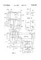
- FIG. 1is a block diagram showing a UHF/VHF antenna system in accordance with the present invention.
- FIGS. 1A and 1Bare simplified plan and side views, respectively, of the radiating elements of FIG. 1.
- FIG. 2is a perspective view of a folded-dipole antenna element usable in the embodiment of FIG. 1.
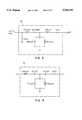
- FIG. 3is a schematic wiring diagram of a low-band VHF antenna matching network.
- FIG. 4.is a schematic wiring diagram of a high-band VHF antenna matching network.
- FIG. 5is a block diagram of a UHF antenna coupler in accordance with the present invention.
- FIG. 6is a detail of a wideband coaxial balun as used in the coupler of FIG. 5.
- FIG. 7is a schematic wiring diagram of a UHF antenna coupler as in the present invention.
- FIG. 8is a sectional view of an antenna system of the present invention as installed in a radome for use with an external VHF antenna.
- FIG. 9is a sectional view of the present invention as installed in a flotation buoy for oceanic communications.
- FIG. 10is a conceptual pictorial of the invention of FIG. 9 as utilized with a tow bridal.
- FIG. 1is a block diagram showing a multifunction UHF/VHF antenna system of the invention.
- the antenna 10comprises a plurality of radiating elements 20-34 disposed in a turnstile arrangement about a central axis y--y.
- Each radiating elementis comprised of first and second serially connected members, with one of the members including upper and lower arms nominally parallel to the axis y--y.
- each radiating elementis comprised, respectively, of members 20, 22A, 22B; 24, 26A, 26B; 28, 30A, 30B; and 32, 34A, 34B; where the suffix A denotes the upper arm and the suffix B denotes the lower arm.
- each pair of associated memberstherefore defines a folded dipole which may be appropriately excited by a signal applied to the segmented member. While a folded dipole is shown to illustrate the invention, it will be clear to one skilled in the art that the upper and lower arms of each radiating element (e.g., arms 22A and 22B) form a basic dipole radiating element, the folded dipole configuration as shown (i.e., including member 20) being provided to achieve improved operating bandwidth. Representations of the radiating elements are shown in FIGS. 1A and 1B, which are simplified plan and side views of the FIG. 1 radiating elements in a basic non-folded dipole format.
- control box 16is configured to connect selectively one of coupling circuits 12 and 13 to the radiating elements in accordance with selection of a predetermined frequency band. It will be shown that in the UHF coupling mode the radiating elements are fed in successive 90 degree relative phase and in the VHF modes in phase, as determined by the relay contact positions of control box 16.
- the antenna systemalso includes a circular metallic reflective ground plate represented at 17.
- FIG. 2provides a perspective view of the assembly.
- a stripline 50 having a total element length of 17.9"was folded to provide an input impedance of nominally 200 ohms.
- a first memberis comprised of upper and lower arms 52 and 54 which are directly coupled to a second member 56 via upper and lower distal portions 58, 60 extending inward from the first and second members to a central axis Y--Y.
- the upper portion 58has a distal length of 4.90" while the lower portion has a distal length of 3.50".
- Arms 52 and 54are separated to provide a gap of 0.25" for accepting a signal feedline.
- member 56has a total width of 2.0" with 0.50" slots.
- Members 52 and 54have a width of 0.50" with a spacing of 1.0" between the first and second members.
- the entire radiating elementmay by formed by conventional stripline or printed circuit techniques.
- the base materialwas 0.003" polyamide (trademarked Kapton) plated with one micron copper.
- Stiffener members 62may optionally be provided at the folds of the base material.
- radiating elementsdisposed at 90° separations comprise a UHF/VHF antenna.
- the radiating elementsoperate as bent folded dipoles at UHF and may be optimized to provide maximum bandwidth.
- the elementsare bent to provide hemispherical coverage with greater gain at lower angles of elevation than at the zenith to compensate for the greater propagation losses at the lower angles.
- conventional dipole elementssuch as represented in FIGS. 1A and 1B or other element designs may be utilized, phased as described, with appropriate impedance matching to meet particular bandwidth and other system requirements.
- FIGS. 3 and 4there are shown circuit diagrams for low band and high band VHF impedance matching networks, respectively, as included in unit 13.
- unit 13when either coupling network 14 or 15 is selected by relay contacts 42 of control unit 16, all antenna elements 20-34 are connected in parallel by relay contacts 40, thereby energizing the elements nominally in phase. Since the antennas operate reciprocally, either in transmit or in receive, this phase relationship will maintain throughout operation in the VHF ranges.
- FIG. 3shows a schematic diagram of an embodiment of a low band VHF matching circuit 14 for coupling a VHF signal to the radiating elements in a nominally 30 to 90 MHz band.
- This circuitwas designed to provide a VSWR that varied from a high value of 2.2 at 40 MHz to a low value of 1.7 at 80 MHz, with an insertion loss varying from 24 dB at the low frequency end to 15 dB at the high frequency end. This resulted in an effective antenna gain of approximately -20 dB at 30 MHz and approximately -11 dB at 88 MHz, for a difference of about 9 dB. Since the propagation loss varies in an inverse manner over this frequency range, the result is to normalize the effective communication range with frequency.
- FIG. 4is a schematic diagram of an embodiment of a high band VHF circuit 15 designed to match the parallel radiating elements over a nominal frequency band of 140 MHz to 190 MHz.
- VSWRwas found to vary between 2.3 at 140 MHz to 1.6 at 180 MHz, while the insertion loss ranged from approximately -8 dB to -6 dB over the range.
- the corresponding antenna gainranged from approximately -4.5 dB at 140 MHz to -2.5 dB at 180 MHz.
- FIG. 5is a block diagram of an embodiment of a UHF matching network for use in the nominal 220-400 MHz frequency band and particularly adapted to matching an array of folded dipoles.
- Dipole antennasare preferably fed by balanced lines which are constructed symmetrically with respect to the feed point.
- a balanced antennashould preferably be fed by a balanced feeder system. This avoids problems due to unbalanced currents and consequential undesirable radiation from the transmission line, which can distort the radiation pattern as well as interfere with associated electronics. Since the coaxial feed line is inherently unbalanced, the network of FIG. 5 is used to isolate the balanced load from the unbalanced line while permitting efficient power transfer.
- the networkcomprises a wideband 3 dB quadrature hybrid coupler 70, a high power isolated port terminating resistor 72, two coaxial 1/4 ⁇ impedance transformers 74, and two coaxial balun networks using Schiffman phase shifters 76.
- the signal Vin applied to the unbalanced 50 ohm input at coupler 70is applied in phase opposition to transformers 74.
- the 25 ohm output thereoffeeds the baluns 76 to provide a 100 ohm balanced output to the folded dipole antenna elements 100.
- the hybrid coupler 70comprises a quarter-wavelength twin center conductor coaxial cable, such as made by Sage Laboratories. This coupler distributes power to each coupler arm with a ratio of 0.5 dB at 400 MHz, the worst case. No noticeable degradation of performance is caused by this small asymmetry between the branches.
- the line lengths of the coupler 70, transformers 74, and phase shifter 76are preferably set to a center frequency of 300 MHz. With a typical application applying a peak power of 100W for a duty cycle of 1/6, a termination capable of dissipating 35W average power is suitable.
- Quarter wave transformer 74is used to transform the impedance from 50 ohms to a nominal value of 25 ohms, and may be formed from 32 or 35 ohm flexible or rigid coaxial cable.
- the 35 ohm cableprovides a more accurate impedance transformation to the desired 25 ohm value, since the 32 ohm cable will result in an output impedance of approximately 20 ohms, resulting in a 1.2:1 mismatch at the center frequency.
- each coaxial balun networkcomprises a one-half wavelength length of RG/U 316 50 ohm cable 90 in parallel with a half wavelength of Wireline twin center conductor 50 ohm coaxial cable 92.
- the center conductors of cable 92are shorted as shown at reference 94, and the two cables are connected in parallel at the 25 ohm input. This creates a 360° path length through the coupled lines and provides a 4:1 impedance transformation at the output.
- the 100 ohm outputis coupled to two 50 ohm coaxial cables 96.
- This balunis known as a Schiffman phase shifter and produces a 180° phase shift between the two output ports.
- equal and opposite voltage polarities to groundare obtained for the balanced lines that follow.
- the wideband coupler 70nominally splits the power evenly and provides a 90° phase shift to impedance transformers 74.
- the 50 ohm quarter wave transformersoperate in a conventional manner to provide a 25 ohm output from a 50 ohm input. This provides a match to the 25 ohm input of the wideband balun 76, which has two 50 ohm lines in parallel as the input.
- the balunconverts the network from an unbalanced to a balanced configuration over a 2:1 frequency band (200-400).
- the balun output voltagesare equal and opposite with respect to ground and effectively convert four 50 ohm transmission lines 90 into two shielded 100 ohm twin lead lines 96A-96D that travel from the coupler housing to a height equal with the antenna feedpoints.
- Each branchthen splits a second time into two parallel 200 ohm coplanar balanced lines 100A-100B, 102A-102B, 104A-104B and 106A-106B, that run from the center conductor to the radiating elements.
- the two outputs 78, 80 and 82,84 corresponding to each pair of 200 ohm linesare phase inverted.
- the arraycan provide left or right hand circular polarization having substantially hemispheric coverage.
- the radiating elementis advantageous to use a folded dipole as the radiating element in this configuration.
- a center-fed half-wave dipole with a characteristic impedance of about 72 ohmsis modified to a two-wire folded half wave dipole, as in FIG. 2, the effect is to multiply the input impedance by a factor of four to approximately 280 ohms.
- Thisis more appropriate for the matching network of this invention and alleviates the need for additional matching components, reducing cost and complexity.
- the radiating elementsare well matched to the 200 ohm coplanar line, not exceeding a VSWR of 2:1 over 240-270 MHz. Performance rolls off to about a 4:1 mismatch at 400 MHz.
- the compact nature of the UHF coupling network and antenna arraylends itself to utility with a radiation-transmissive radome 110 of overall dimensions of 12 inches in height and 12 inches in diameter, as shown in cross-section in the simplified view of FIG. 8.
- a circular reflective ground plate 17having a nominal 12 inch diameter will be suitable at UHF frequencies.
- the radomemay be utilized at VHF by collectively exciting the radiating elements of antenna 10 as a monopole, cooperating with the reflecting ground plane, as heretofore described, and additional capabilities may be provided via an external antenna or other sensor, such as a global position system antenna, mounted atop the radome at antenna mount 112.
- Other appropriate physical arrangementssuch as feed and electrical housings 114 and 116, RF connections 118 and power connection 120, can be provided by skilled persons.
- an antenna system in accordance with the inventionmay by enclosed within a radome/housing 110A and supported for floatation above the surface of the ocean, as in FIG. 9.
- the water surfaceacts as a reflecting ground plane with ground plate 17, and the floatation device enables operation over a range of sea conditions.
- a whip antenna 122is shown affixed to antenna mount 112.
- the apparatusWhen used with the radome enclosure and floatation device, the apparatus is suitable to be provided with a tow line connection assembly 124 as in FIG. 10, thus enabling the enclosure to be towed by a vessel.
- Signalscan be coupled between the vessel and the antenna system by suitable cabling (not shown) which is configured to cooperate with the tow line assembly.
- Control planes 126may be included to permit adjustment of the tow attitude.
- UHF signalis defined as a signal within a range of frequencies, which range includes at least a portion of the band from 220 to 400 MHz.
- VHF signalis defined as a signal within a range of frequencies, which range includes at least a portion of the band from 30 to 190 MHz.
Landscapes
- Variable-Direction Aerials And Aerial Arrays (AREA)
Abstract
Description
Claims (22)
Priority Applications (2)
| Application Number | Priority Date | Filing Date | Title |
|---|---|---|---|
| US08/685,812US5764195A (en) | 1996-07-24 | 1996-07-24 | UHF/VHF multifunction ocean antenna system |
| GB9715820AGB2315603B (en) | 1996-07-24 | 1997-07-23 | Antenna system |
Applications Claiming Priority (1)
| Application Number | Priority Date | Filing Date | Title |
|---|---|---|---|
| US08/685,812US5764195A (en) | 1996-07-24 | 1996-07-24 | UHF/VHF multifunction ocean antenna system |
Publications (1)
| Publication Number | Publication Date |
|---|---|
| US5764195Atrue US5764195A (en) | 1998-06-09 |
Family
ID=24753770
Family Applications (1)
| Application Number | Title | Priority Date | Filing Date |
|---|---|---|---|
| US08/685,812Expired - Fee RelatedUS5764195A (en) | 1996-07-24 | 1996-07-24 | UHF/VHF multifunction ocean antenna system |
Country Status (2)
| Country | Link |
|---|---|
| US (1) | US5764195A (en) |
| GB (1) | GB2315603B (en) |
Cited By (16)
| Publication number | Priority date | Publication date | Assignee | Title |
|---|---|---|---|---|
| US6014107A (en)* | 1997-11-25 | 2000-01-11 | The United States Of America As Represented By The Secretary Of The Navy | Dual orthogonal near vertical incidence skywave antenna |
| US6417816B2 (en)* | 1999-08-18 | 2002-07-09 | Ericsson Inc. | Dual band bowtie/meander antenna |
| US6515628B2 (en)* | 2000-07-31 | 2003-02-04 | Andrew Corporation | Dual polarization patch antenna |
| US6618016B1 (en) | 2001-02-21 | 2003-09-09 | Bae Systems Aerospace Inc. | Eight-element anti-jam aircraft GPS antennas |
| US20050208986A1 (en)* | 2004-03-17 | 2005-09-22 | Best Fiona S | Four frequency band single GSM antenna |
| US20050210235A1 (en)* | 2004-03-17 | 2005-09-22 | Best Fiona S | Encryption STE communications through private branch exchange (PBX) |
| US20050210234A1 (en)* | 2004-03-17 | 2005-09-22 | Best Fiona S | Reach-back communications terminal with selectable networking options |
| US20050243014A1 (en)* | 2004-05-03 | 2005-11-03 | Bryan John W Jr | Ground proximity antenna system |
| US20060232477A1 (en)* | 2005-04-15 | 2006-10-19 | Nokia Corporation | Antenna having a plurality of resonant frequencies |
| US20060270451A1 (en)* | 2004-03-17 | 2006-11-30 | Best Fiona S | Secure transmission over satellite phone network |
| US20070164553A1 (en)* | 2006-01-17 | 2007-07-19 | Dov Katz | Coloring book with embedded inwardly foldable stencils |
| US20130022133A1 (en)* | 2011-07-19 | 2013-01-24 | Tektronix, Inc. | Wideband Balun Structure |
| WO2015140117A1 (en)* | 2014-03-18 | 2015-09-24 | Thyssenkrupp Marine Systems Gmbh | Device for transmitting and/or receiving electromagnetic waves |
| US9941950B2 (en) | 2014-12-11 | 2018-04-10 | Skywave Networks Llc | Communication method and system that uses low latency/low data bandwidth and high latency/high data bandwidth pathways |
| US11218215B2 (en) | 2017-10-02 | 2022-01-04 | Skywave Networks Llc | Optimizing the location of an antenna system in a low latency/low data bandwidth link used in conjunction with a high latency/high bandwidth link |
| US11496210B2 (en) | 2017-10-04 | 2022-11-08 | Skywave Networks Llc | Adjusting transmissions based on direct sensing of the ionosphere |
Families Citing this family (3)
| Publication number | Priority date | Publication date | Assignee | Title |
|---|---|---|---|---|
| US6549242B1 (en)* | 1997-04-04 | 2003-04-15 | Harris Corporation | Combining adjacent TV channels for transmission by a common antenna |
| GB2414800B (en)* | 2000-01-27 | 2006-05-31 | Thomson Marconi Sonar Ltd | Sonar receiver with low side lobes |
| WO2024232848A1 (en)* | 2023-05-10 | 2024-11-14 | Plan S Uydu Ve Uzay Teknoloji̇leri̇ A.Ş. | A turnstile antenna |
Citations (8)
| Publication number | Priority date | Publication date | Assignee | Title |
|---|---|---|---|---|
| US2581444A (en)* | 1949-09-28 | 1952-01-08 | Standard Telephones Cables Ltd | Direction finder |
| US3312902A (en)* | 1964-06-29 | 1967-04-04 | Mcdonnell Aircraft Corp | Self-erecting floating structure |
| US3972046A (en)* | 1975-08-25 | 1976-07-27 | International Telephone And Telegraph Corporation | Antenna arrangement for a submerged submarine |
| US4083051A (en)* | 1976-07-02 | 1978-04-04 | Rca Corporation | Circularly-polarized antenna system using tilted dipoles |
| US4180820A (en)* | 1977-09-28 | 1979-12-25 | Rca Corporation | Circularly polarized antenna system using a combination of horizontal and bent vertical dipole radiators |
| US4434425A (en)* | 1982-02-02 | 1984-02-28 | Gte Products Corporation | Multiple ring dipole array |
| US5187488A (en)* | 1989-11-14 | 1993-02-16 | Nederlandse Organisatie Voor Toegepast-Natuurwetenschappelijk Onderzoek Tno | Tunable high-frequency antenna |
| US5534882A (en)* | 1994-02-03 | 1996-07-09 | Hazeltine Corporation | GPS antenna systems |
Family Cites Families (5)
| Publication number | Priority date | Publication date | Assignee | Title |
|---|---|---|---|---|
| DE1591629C3 (en)* | 1967-01-04 | 1974-08-08 | Telefunken Patentverwertungsgesellschaft Mbh, 7900 Ulm | Antenna with horizontally polarized half-wave folded dipole and a two-wire line leading downwards |
| JPS5748806A (en)* | 1980-09-08 | 1982-03-20 | Nippon Telegr & Teleph Corp <Ntt> | Base station antenna for common use of four groups |
| FR2518321A1 (en)* | 1981-12-15 | 1983-06-17 | Thomson Csf | RADIANT ASSEMBLY WITH TWO SUPERPOSED ANTENNAS WORKING IN THE SAME RANGE OF FREQUENCIES |
| US5032844A (en)* | 1989-03-21 | 1991-07-16 | Southwest Research Institute | Sky wave direction finder |
| US5346300A (en)* | 1991-07-05 | 1994-09-13 | Sharp Kabushiki Kaisha | Back fire helical antenna |
- 1996
- 1996-07-24USUS08/685,812patent/US5764195A/ennot_activeExpired - Fee Related
- 1997
- 1997-07-23GBGB9715820Apatent/GB2315603B/ennot_activeExpired - Fee Related
Patent Citations (8)
| Publication number | Priority date | Publication date | Assignee | Title |
|---|---|---|---|---|
| US2581444A (en)* | 1949-09-28 | 1952-01-08 | Standard Telephones Cables Ltd | Direction finder |
| US3312902A (en)* | 1964-06-29 | 1967-04-04 | Mcdonnell Aircraft Corp | Self-erecting floating structure |
| US3972046A (en)* | 1975-08-25 | 1976-07-27 | International Telephone And Telegraph Corporation | Antenna arrangement for a submerged submarine |
| US4083051A (en)* | 1976-07-02 | 1978-04-04 | Rca Corporation | Circularly-polarized antenna system using tilted dipoles |
| US4180820A (en)* | 1977-09-28 | 1979-12-25 | Rca Corporation | Circularly polarized antenna system using a combination of horizontal and bent vertical dipole radiators |
| US4434425A (en)* | 1982-02-02 | 1984-02-28 | Gte Products Corporation | Multiple ring dipole array |
| US5187488A (en)* | 1989-11-14 | 1993-02-16 | Nederlandse Organisatie Voor Toegepast-Natuurwetenschappelijk Onderzoek Tno | Tunable high-frequency antenna |
| US5534882A (en)* | 1994-02-03 | 1996-07-09 | Hazeltine Corporation | GPS antenna systems |
Cited By (36)
| Publication number | Priority date | Publication date | Assignee | Title |
|---|---|---|---|---|
| US6014107A (en)* | 1997-11-25 | 2000-01-11 | The United States Of America As Represented By The Secretary Of The Navy | Dual orthogonal near vertical incidence skywave antenna |
| US6417816B2 (en)* | 1999-08-18 | 2002-07-09 | Ericsson Inc. | Dual band bowtie/meander antenna |
| US6515628B2 (en)* | 2000-07-31 | 2003-02-04 | Andrew Corporation | Dual polarization patch antenna |
| US6618016B1 (en) | 2001-02-21 | 2003-09-09 | Bae Systems Aerospace Inc. | Eight-element anti-jam aircraft GPS antennas |
| US7761095B2 (en) | 2004-03-17 | 2010-07-20 | Telecommunication Systems, Inc. | Secure transmission over satellite phone network |
| US8913989B2 (en) | 2004-03-17 | 2014-12-16 | Telecommunication Systems, Inc. | Secure transmission over satellite phone network |
| US20050210234A1 (en)* | 2004-03-17 | 2005-09-22 | Best Fiona S | Reach-back communications terminal with selectable networking options |
| US20050210235A1 (en)* | 2004-03-17 | 2005-09-22 | Best Fiona S | Encryption STE communications through private branch exchange (PBX) |
| US8489874B2 (en) | 2004-03-17 | 2013-07-16 | Telecommunication Systems, Inc. | Encryption STE communications through private branch exchange (PBX) |
| US20060270451A1 (en)* | 2004-03-17 | 2006-11-30 | Best Fiona S | Secure transmission over satellite phone network |
| US20060271779A1 (en)* | 2004-03-17 | 2006-11-30 | Best Fiona S | Faceplate for quick removal and securing of encryption device |
| US8280466B2 (en)* | 2004-03-17 | 2012-10-02 | Telecommunication Systems, Inc. | Four frequency band single GSM antenna |
| US8239669B2 (en) | 2004-03-17 | 2012-08-07 | Telecommunication Systems, Inc. | Reach-back communications terminal with selectable networking options |
| US20110237247A1 (en)* | 2004-03-17 | 2011-09-29 | Best Fiona S | Secure transmission over satellite phone network |
| US7890051B2 (en) | 2004-03-17 | 2011-02-15 | Telecommunication Systems, Inc. | Secure transmission over satellite phone network |
| US20050208986A1 (en)* | 2004-03-17 | 2005-09-22 | Best Fiona S | Four frequency band single GSM antenna |
| US20100124330A1 (en)* | 2004-03-17 | 2010-05-20 | Best Fiona S | Secure transmission over satellite phone network |
| US7724902B2 (en) | 2004-03-17 | 2010-05-25 | Telecommunication Systems, Inc. | Faceplate for quick removal and securing of encryption device |
| US20050243014A1 (en)* | 2004-05-03 | 2005-11-03 | Bryan John W Jr | Ground proximity antenna system |
| US7199763B2 (en) | 2004-05-03 | 2007-04-03 | Lockheed Martin Corporation | Ground proximity antenna system |
| US7705791B2 (en) | 2005-04-15 | 2010-04-27 | Nokia Corporation | Antenna having a plurality of resonant frequencies |
| US20080211725A1 (en)* | 2005-04-15 | 2008-09-04 | Nokia Corporation | Antenna having a plurality of resonant frequencies |
| US20060232477A1 (en)* | 2005-04-15 | 2006-10-19 | Nokia Corporation | Antenna having a plurality of resonant frequencies |
| US7629931B2 (en)* | 2005-04-15 | 2009-12-08 | Nokia Corporation | Antenna having a plurality of resonant frequencies |
| US20070164553A1 (en)* | 2006-01-17 | 2007-07-19 | Dov Katz | Coloring book with embedded inwardly foldable stencils |
| US20130022133A1 (en)* | 2011-07-19 | 2013-01-24 | Tektronix, Inc. | Wideband Balun Structure |
| US8611436B2 (en)* | 2011-07-19 | 2013-12-17 | Tektronix, Inc. | Wideband balun structure |
| KR20160133527A (en)* | 2014-03-18 | 2016-11-22 | 티쎈크로프 마리네 지스템스 게엠베하 | Device for transmitting and/or receiving electromagnetic waves |
| WO2015140117A1 (en)* | 2014-03-18 | 2015-09-24 | Thyssenkrupp Marine Systems Gmbh | Device for transmitting and/or receiving electromagnetic waves |
| KR101951532B1 (en) | 2014-03-18 | 2019-02-22 | 티쎈크로프 마리네 지스템스 게엠베하 | Device for transmitting and/or receiving electromagnetic waves |
| US9941950B2 (en) | 2014-12-11 | 2018-04-10 | Skywave Networks Llc | Communication method and system that uses low latency/low data bandwidth and high latency/high data bandwidth pathways |
| US10778323B2 (en) | 2014-12-11 | 2020-09-15 | Skywave Networks Llc | Communication method and system that uses low latency/low data bandwidth and high latency/high data bandwidth pathways |
| US11581940B2 (en) | 2014-12-11 | 2023-02-14 | Skywave Networks Llc | Communication method and system that uses low latency/low data bandwidth and high latency/high data bandwidth pathways |
| US11218215B2 (en) | 2017-10-02 | 2022-01-04 | Skywave Networks Llc | Optimizing the location of an antenna system in a low latency/low data bandwidth link used in conjunction with a high latency/high bandwidth link |
| US11496210B2 (en) | 2017-10-04 | 2022-11-08 | Skywave Networks Llc | Adjusting transmissions based on direct sensing of the ionosphere |
| US12068837B2 (en) | 2017-10-04 | 2024-08-20 | Skywave Networks Llc | Adjusting transmissions based on direct sensing of the ionosphere |
Also Published As
| Publication number | Publication date |
|---|---|
| GB2315603B (en) | 2000-12-27 |
| GB9715820D0 (en) | 1997-10-01 |
| GB2315603A (en) | 1998-02-04 |
Similar Documents
| Publication | Publication Date | Title |
|---|---|---|
| US5764195A (en) | UHF/VHF multifunction ocean antenna system | |
| US5173715A (en) | Antenna with curved dipole elements | |
| US4814777A (en) | Dual-polarization, omni-directional antenna system | |
| US4208660A (en) | Radio frequency ring-shaped slot antenna | |
| US6133891A (en) | Quadrifilar helix antenna | |
| CA2343729C (en) | Circularly polarized dielectric resonator antenna | |
| US5070340A (en) | Broadband microstrip-fed antenna | |
| US4527163A (en) | Omnidirectional, circularly polarized, cylindrical microstrip antenna | |
| US7629939B2 (en) | Broadband dual polarized base station antenna | |
| US6720935B2 (en) | Single and dual-band patch/helix antenna arrays | |
| US5608413A (en) | Frequency-selective antenna with different signal polarizations | |
| US4812855A (en) | Dipole antenna with parasitic elements | |
| US3740754A (en) | Broadband cup-dipole and cup-turnstile antennas | |
| US4864320A (en) | Monopole/L-shaped parasitic elements for circularly/elliptically polarized wave transceiving | |
| US4369449A (en) | Linearly polarized omnidirectional antenna | |
| US20120081259A1 (en) | Inverted-U Crossed-Dipole Satcom Antenna | |
| US20080266181A1 (en) | Antenna Arrangement | |
| US6064348A (en) | Method and apparatus for a dual frequency band antenna | |
| US6344834B1 (en) | Low angle, high angle quadrifilar helix antenna | |
| US5818397A (en) | Circularly polarized horizontal beamwidth antenna having binary feed network with microstrip transmission line | |
| US11502414B2 (en) | Microstrip patch antenna system having adjustable radiation pattern shapes and related method | |
| US20170237174A1 (en) | Broad Band Diversity Antenna System | |
| US20210273339A1 (en) | Wideband Dual-Polarized Four-Quad Loop Antenna | |
| US6288686B1 (en) | Tapered direct fed quadrifilar helix antenna | |
| EP0431764B1 (en) | Antenna with curved dipole elements |
Legal Events
| Date | Code | Title | Description |
|---|---|---|---|
| AS | Assignment | Owner name:HAZELTINE CORPORATION, NEW YORK Free format text:ASSIGNMENT OF ASSIGNORS INTEREST;ASSIGNORS:COLCLOUGH, LINDSLEY D.;GLENN, RICHARD J.;KUMPFBECK, RICHARD J.;REEL/FRAME:008293/0452;SIGNING DATES FROM 19961003 TO 19961011 | |
| FPAY | Fee payment | Year of fee payment:4 | |
| AS | Assignment | Owner name:ULTRA ELECTRONICS OCEAN SYSTEMS INC., MASSACHUSETT Free format text:ASSIGNMENT OF ASSIGNORS INTEREST;ASSIGNOR:BAE SYSTEMS INFORMATION AND ELECTRIC SYSTEMS INTEGRATION INC.;REEL/FRAME:014178/0888 Effective date:20031120 | |
| AS | Assignment | Owner name:GEC-MARCONI HAZELTINE CORPORATION, NEW YORK Free format text:MERGER & CHANGE OF NAME;ASSIGNOR:HAZELTINE CORPORATION;REEL/FRAME:015201/0676 Effective date:19980415 Owner name:MARCONI AEROSPACE SYSTEMS INC., NEW YORK Free format text:CHANGE OF NAME;ASSIGNOR:GEC-MARCONI HAZELTINE CORPORATION;REEL/FRAME:015201/0684 Effective date:20020725 Owner name:BAE SYSTEMS AEROSPACE INC., NEW YORK Free format text:CHANGE OF NAME;ASSIGNOR:MARCONI AEROSPACE SYSTEMS INC.;REEL/FRAME:015201/0689 Effective date:20000214 Owner name:BAE SYSTEMS INFORMATION AND ELECTRONIC SYSTEMS INT Free format text:MERGER;ASSIGNOR:BAE SYSTEMS AEROSPACE INC.;REEL/FRAME:015201/0691 Effective date:20021120 | |
| REMI | Maintenance fee reminder mailed | ||
| LAPS | Lapse for failure to pay maintenance fees | ||
| STCH | Information on status: patent discontinuation | Free format text:PATENT EXPIRED DUE TO NONPAYMENT OF MAINTENANCE FEES UNDER 37 CFR 1.362 | |
| FP | Expired due to failure to pay maintenance fee | Effective date:20060609 |