US5764061A - Maritime apparatus for locating a buried submarine cable - Google Patents
Maritime apparatus for locating a buried submarine cableDownload PDFInfo
- Publication number
- US5764061A US5764061AUS08/738,698US73869896AUS5764061AUS 5764061 AUS5764061 AUS 5764061AUS 73869896 AUS73869896 AUS 73869896AUS 5764061 AUS5764061 AUS 5764061A
- Authority
- US
- United States
- Prior art keywords
- submarine cable
- sup
- magnetic sensing
- magnetic
- triaxial orthogonal
- Prior art date
- Legal status (The legal status is an assumption and is not a legal conclusion. Google has not performed a legal analysis and makes no representation as to the accuracy of the status listed.)
- Expired - Fee Related
Links
Images


Classifications
- G—PHYSICS
- G01—MEASURING; TESTING
- G01V—GEOPHYSICS; GRAVITATIONAL MEASUREMENTS; DETECTING MASSES OR OBJECTS; TAGS
- G01V3/00—Electric or magnetic prospecting or detecting; Measuring magnetic field characteristics of the earth, e.g. declination, deviation
- G01V3/15—Electric or magnetic prospecting or detecting; Measuring magnetic field characteristics of the earth, e.g. declination, deviation specially adapted for use during transport, e.g. by a person, vehicle or boat
- G—PHYSICS
- G01—MEASURING; TESTING
- G01V—GEOPHYSICS; GRAVITATIONAL MEASUREMENTS; DETECTING MASSES OR OBJECTS; TAGS
- G01V3/00—Electric or magnetic prospecting or detecting; Measuring magnetic field characteristics of the earth, e.g. declination, deviation
- G01V3/02—Electric or magnetic prospecting or detecting; Measuring magnetic field characteristics of the earth, e.g. declination, deviation operating with propagation of electric current
Definitions
- This inventionrelates to an apparatus for locating the whereabouts of a buried submarine cable.
- the buried submarine cableis impressed with alternating current of around 20 Hz beforehand to produce an ac magnetic field, which is then detected by ac magnetic sensors, enabling an operator to find out the location of the buried submarine cable.
- This methodhas excellent features such as high sensitivity, capability of measuring the relative position, direction ,and burial depth of submarine cables and so on.
- this methodhas problems when applied to buried submarine cables extended over a long distance; one problem being difficulty in detecting a cable at a far-away spot due to the strength of ac attenuating as it propagates, and another problem being the impracticability of impressing some outdated coaxial cables still in the field with ac even when prior survey of the laid condition of a submarine cable in the field is required to prevent damages.
- a submarine cable locating system using non-directional dc magnetic sensorshas also been well known.
- a submarine cableis detected by sensing dc supplied to the submarine cable and a dc magnetic field created by armoring steel wires of the submarine cable; the submarine cable is impressed with dc to supply electric power to relays interposed at some points along the whole length of the submarine cable.
- a submersible robotis provided with a or a plurality of differential triaxial orthogonal dc magnetic sensing units each comprising two triaxial orthogonal dc magnetic sensors spaced at an adequate distance apart and with their corresponding axes set in parallel; each of the triaxial orthogonal dc magnetic sensors incorporating therein three dc magnetic sensing elements each sensitive only to a dc magnetic field in a specific axial direction and disposed such that the axes of respective dc magnetic sensing elements cross each other at right angles so that the output of a or the plurality of differential triaxial orthogonal dc magnetic sensing units are converted into digital signals through an analog-to-digital (A/D) converter, and processed by a processing unit.
- A/Danalog-to-digital
- the processing unitis capable of computing the distance to the submarine cable, a difference in elevation between the submersible robot and the submarine cable, and the direction in which the submarine cable is laid down by performing computation on the basis of a difference in output between the two dc magnetic sensors with their corresponding axes set in parallel and incorporated in each of the differential triaxial orthogonal dc magnetic sensing units.
- the processing unitis capable of determining the position of the submarine cable by compensating for fluctuation in the sensitivity and offset of the dc magnetic sensing elements and angular deviations of respective axes thereof and computing on the basis of the results obtained after such compensating operation.
- the submersible robotis rotated once at an underwater spot in a uniform dc magnetic field where neither magnetic substance such as a submarine cable nor direct current is present to measure correlation between the bearings of the submersible robot during such rotation and the output of the differential triaxial orthogonal dc magnetic sensing units; such data are stored in a memory.
- the data retrieved from the memoryany variation in the output of the differential triaxial orthogonal dc magnetic sensing units due to the rotation of the submersible robot is compensated for.
- the differential triaxial orthogonal dc magnetic sensing unitsare fixed to and enclosed in a container to prevent the distortion of the axes of the dc magnetic sensing elements due to expansion or contraction thereof caused by seawater pressure in deep sea and changes in the temperature of seawater; the container is securely attached to a pressure-resistant vessel through a soft buffer such as a rubber member.
- the container enclosing the differential triaxial orthogonal dc magnetic sensing unitsis made of high strength insulating material.
- FIG. 1illustrates an operation to detect a submarine cable by the submarine cable locating system according to the invention
- FIG. 2is a block diagram showing the shipboard and underwater portions of a submarine cable locating system according to the invention
- FIG. 3(a)is an external view of a differential triaxial orthogonal dc magnetic sensing unit
- FIG. 3(b)shows a constitution inside a cylindrical container enclosing a differential triaxial orthogonal dc magnetic sensing unit
- FIG. 4illustrates coordinate systems employed for computation of the position and direction of a submarine cable laid down
- FIG. 5illustrates a coordinate system employed for computation of the position of a submarine cable
- FIG. 6shows an example of display shown on a display installed in a mother ship
- FIG. 7shows other examples of display shown on a display installed in a mother ship.
- FIG. 8illustrates an example of calibrating a sensor on a calibration table.
- FIG. 1illustrates an operation to locate a submarine cable by a submarine cable locating system according to the invention.
- reference numeral 7indicates a sea bed surface, 8 a submarine cable buried under the sea bed surface, 10 a remotely operated submersible robot, and 20 a mother ship;
- reference numerals 1 and 2indicate two differential triaxial orthogonal dc magnetic sensing units, 3 an electronic circuit casing, 4 a thruster, and 5 support frames, all of which are installed in the submersible robot 10.
- Reference numeral 6indicates a tether cable connecting the submersible robot 10 to the mother ship 20.
- the two differential triaxial orthogonal dc magnetic sensing units 1 and 2are fixedly attached to the support frames 5 provided on the right and left sides of the forward part of the submersible robot 10, respectively, but as far off as possible therefrom to minimize the effect of a dc magnetic field created by the body of the submersible robot 10 which is made of magnetic material such as steel or the like.
- the submersible robot 10is provided with a buoyancy member (not shown) to reduce its underwater weight to zero enabling it to move about freely, back and forth, and right and left, by means of a plurality of thrusters 4.
- the submersible robot 10 connected to the mother ship 20 through the tether cable 6is supplied with electric power by the mother ship 20 and remotely operated by an operator on board the mother ship.
- the submersible robot 10is further provided with, although not shown, an inclinometer for measuring the attitude thereof, a TV camera, a water jetting device used in burying a submarine cable, and the like. Signals of various sensors and the TV camera are transmitted in real time via a signal transmitter housed in the electronic circuit casing 3 and the tether cable 6 to the mother ship 20 to be monitored by the operator.
- FIG. 1shows a coordinate system (X 3 , Y 3 , Z 3 ) fixed to the submersible robot; the X3-axis points straight forward from the submersible robot, the Y 3 -axis extends to the right viewed from the submersible robot, and the Z 3 -axis extends straight downward from the submersible robot while the origin of the coordinate system is positioned substantially at the center between the two differential triaxial orthogonal dc magnetic sensing units.
- the coordinate systemwill be used hereafter in explaining a method of computing the position and direction of a submarine cable.
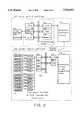
- FIG. 2is a block diagram showing a system constitution of an embodiment according to the invention.
- reference numeral 30denotes an underwater portion mounted in the submersible robot 10 and 40 a shipboard portion in the mother ship 20.
- two differential triaxial orthogonal dc magnetic sensing units 1 and 2 as stated aboveare in use, each comprising two triaxial orthogonal dc magnetic sensors; each of the triaxial orthogonal dc magnetic sensors incorporates therein three dc magnetic sensing elements.
- the dc magnetic sensing elements in useare of the type having sensitivity toward a specific axial direction only, for example, flux gate type magnetic sensing elements.
- the dc magnetic sensing elementsare designated sensor 1U x , sensor 1U y , sensor 1U z , sensor 1D x , sensor 1D y , sensor 1D z , sensor 2U x , sensor 2U y , sensor 2U z , sensor 2D x , sensor 2D y , and sensor 2D z , respectively, where numerals 1 and 2 after “sensor” denote identification numbers for each of the two differential triaxial orthogonal dc magnetic sensing units whereas symbols “U” and “D” denote identification numbers for each of the two triaxial orthogonal dc magnetic sensors constituting respective differential triaxial orthogonal dc magnetic sensing units, and suffixes "x", "y", and “z” indicate the direction of sensitivity of each of the three dc magnetic sensing elements constituting respective triaxial orthogonal dc magnetic sensors.
- reference numerals 1 and 2denote the differential triaxial orthogonal dc magnetic sensing units
- 32 1 through 32 12are respective electronic circuits each comprising a low-pass filter and an A/D converter
- 33 and 37are interface circuits
- 34is a central processing unit (CPU) for controlling the whole of the underwater portion
- 35is a memory (RAM)
- 36is a ROM storing a control program and the like
- 38is an electronic circuit of the submersible robot 10 proper incorporating a signal transmitter for transferring signals to the shipboard portion 40 via the tether cable 6.
- reference numeral 39indicates a bus for transferring signals among the CPU 34, the memory 35, the ROM 36, and the interfaces 33 and 37.
- reference numeral 41denotes a shipboard electronic circuit for the submersible robot 10 incorporating a signal transmitter for transferring data between the shipboard portion 40 and the underwater portion 30, 42 is an interface circuit connected to the shipboard electronic circuit 41 for the submersible robot, 43 is a CPU, 44 is a memory such as a hard disk and the like, 45 is a memory, 46 is a video interface circuit, and 47 is an interface circuit for a keyboard 49; reference numerals 42 through 47 constitute a processing unit. Further, reference numeral 48 denotes a video monitor (display) connected to the video interface circuit 46 and 49 is the keyboard connected to the interface circuit 47.
- Output signals sent out from respective electronic circuits 32 1 to 32 12 after analog-to-digital conversionare read into the CPU 34 via the interface circuit 33 and the bus 39, and after preprocessing such as filtering, delivered to the signal transmitter in the underwater electronic circuit 38 inside the underwater portion of the submersible robot via the interface circuit 37 for transmission to the shipboard portion 40 via a signal transmission route within the tether cable 6.
- signals transmitted via the tether cable 6are received by the signal transmitter within the shipboard electronic circuit 41 for the submersible robot and sent out via the interface circuit 42 to the processing unit comprising the CPU 43, the memory 45, the hard disk 44, the keyboard 49, the video interface 46, the interface (I/O) circuit 47, and the like wherein data are processed to compute the position and direction of the submarine cable 8.
- the results obtained by such processing of the dataare displayed on the video monitor 48 and stored in the hard disk 44 simultaneously.
- FIG. 3(a) and (b)illustrate a form of the constitution of a differential triaxial orthogonal dc magnetic sensing unit according to the invention.
- FIG. 3(a)is an external view of a differential triaxial orthogonal dc magnetic sensing unit showing a pressure-resistant vessel 51, buffer members 52, a cylindrical container 53 made of molten quartz, an underwater connector 54, and an underwater cable 55 for delivering the output of the differential triaxial orthogonal dc magnetic sensing unit to the electronic circuit installed inside the submersible robot 10 proper.
- the cylindrical container 53 made of molten quartzis secured inside the pressure-resistant vessel 51 by the medium of the buffer members 52 made of soft material, for example, rubber and the like.
- the cylindrical container 53 made of molten quartzcontains a first triaxial orthogonal dc magnetic sensor incorporating three dc magnetic sensing elements, U x , U y and U z , each having sensitivity to the direction of X-axis, Y-axis, and Z-axis, respectively, and a second triaxial orthogonal dc magnetic sensor incorporating three dc magnetic sensing elements, D x , D y , and D z , each having sensitivity to the direction of X-axis, Y-axis, and Z-axis, respectively; the first and second triaxial orthogonal dc magnetic sensors are spaced a predetermined distance apart and combined to form a differential triaxial orthogonal dc magnetic sensing unit.
- an electronic circuit 56is installed between the first and second triaxial orthogonal sensors; the electronic circuit 56 together with the dc magnetic sensing units, U x , U y , U z , D x , D y , and D z are embedded in synthetic resin (not shown) in the shape of a cylinder, which is inserted in the cylindrical container 53 made of molten quartz.
- the material used for the cylindrical container 53was molten quartz, but need not be limited to the same. Any material other than molten quartz may be used for the purpose as long as it has high Young's modulus and low coefficient of thermal expansion.
- metalis employed as material for the pressure-resistant vessel 51 for use in deep sea, but when a metallic pressure-resistant vessel moves about underwater crossing the terrestrial magnetic field, eddy currents are generated inside the metal, causing disturbance in the magnetic field surrounding the dc magnetic sensing elements owing to a magnetic field created by the eddy currents.
- the problem of such disturbance in the magnetic field generating noises in the output of the dc magnetic sensing elementsmay be solved by use of insulating synthetic resin in place of metal as material for the pressure-resistant vessel.
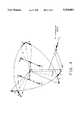
- FIG. 4is a diagrammatic illustration of coordinate systems for explaining the position and direction of a submarine cable; in this figure, X 3 , Y 3 , and Z 3 axes represent a coordinate system fixed to the submersible robot 10 as shown in FIG. 1 while X 0 , Y 0 , and Z 0 axes represent a coordinate system fixed to the surface of the earth.
- the sensitive directions of respective dc magnetic sensing elementsare in parallel with X 3 -axis ,Y 3 -axis, or Z 3 -axis, respectively, and the direction of X 0 -axis is defined to be in parallel with the cable 8.
- Euler's angles denoting the degrees of rotation of the submersible robotare designated , ⁇ , ⁇ , and ⁇ , respectively, in other words, a coordinate system (X 1 , Y 1 , Z 1 ) is set up by rotating the coordinate system (X 0 , Y 0 , Z 0 ) by ⁇ around the Z 0 -axis, a coordinate system (X 2 , Y 2 , Z 2 ) is set up by rotating the coordinate system (X 1 , Y 1 , Z 1 ) by ⁇ around the Y 1 -axis and finally a coordinate system of (X 3 , Y 3 , Z 3 ) is set up by rotating the coordinate system (X 2 , Y 2 and Z 2 ) by ⁇ around the X 2 -axis where ⁇ is a crossing angle formed by the submersible robot 10 and the cable 8 while ⁇ and ⁇ correspond to the magnitude of pitching and rolling of the submersible robot, respectively; the pitching angle ⁇ and the rolling angle
- ⁇ H 1 .sup.(3)which is a difference between the vector H 11 .sup.(3) and the vector H 12 .sup.(3), is defined by the following formulas:
- ⁇ H 1x .sup.(3), ⁇ H 1y .sup.(3), and ⁇ H 1z .sup.(3)which are the X-axis component, Y-axis component, and Z-axis component, respectively, of ⁇ H 1 .sup.(3), shown in the formulas (2) to (4) above are none other than the output of the differential triaxial orthogonal dc magnetic sensing unit 1.
- Formula (5) aboveis derived from the formulas (2) to (4) and (11) and (12) above.
- a horizontal distance y to a submarine cable 8 and an elevation difference z of the submarine cable 8are computed by the following formulas (13) and (14): ##EQU6##
- Irepresents the value for the amount of dc flowing in the submarine cable 8 and is defined positive when flowing in the direction of the arrow along +X 0 -axis as shown in FIG. 4.
- the value I of dc supplied to the submarine cablecan be measured normally at a terminal station onshore. (formulas (13) and (14) are derived)
- the pitching ⁇ and the rolling ⁇ of the submersible robot 10are computed on the coordinate system (X 0 ,Y 0 ,Z 0 ) on the assumption that the values thereof are negligible.
- FIG. 5shows the coordinate system employed in this computation.
- w cos ⁇represents the distance between the two differential triaxial orthogonal dc magnetic sensing units 1 and 2.
- ⁇ H 1y .sup.(0), ⁇ H 1z .sup.(0), and ⁇ H 1 .sup.(0)are defined as follows: ##EQU12##
- the angle and position of the submarine cablecan be computed using the vector H 21 .sup.(0) and H 22 .sup.(0).
- adopting the mean value of the computation results of the sensing units disposed on both sidesis preferable.
- the relative position y and z of the submarine cable 8is obtainable by the following procedure using the two differential triaxial orthogonal dc magnetic sensing units.
- the relative position of the submarine cableis computed as follows using the outputs of the differential triaxial orthogonal dc magnetic sensing units on both sides and formulas (13) and (14): ##EQU21## where the computation results by the sensing unit 1 (position vector P 11 and P 12 ) on the right side are y 1+ and z 1+ , same by the sensing unit 2 (position vector P 21 and P 22 ) on the left side are y 2+ and Z 2+ , and a difference in the results of computation on the relative position of the submarine cable between the sensing units on both sides of the submersible robot is ⁇ D + .
- the relative position of the submarine cableis computed in the same way as stated above using the outputs of the differential triaxial orthogonal dc magnetic sensing units on both sides and formulas (13) and (14) as follows: ##EQU22## where the computation results by the sensing unit 1 (position vector P 11 and P 12 ) on the right side are y 1- and z 1- , same by the sensing unit 2 (position vector P 21 and P 22 ) on the left side are y 2- and z 2- and a difference in the results of computation on the relative position of the submarine cable between the sensing units on both sides of the submersible robot is ⁇ D.
- the relative position of the submarine cableis obtained from formulas (13) and (14) by assuming that I>0 in case of ⁇ D - > ⁇ D + and I ⁇ 0 in case of ⁇ D - ⁇ D + .
- the relative position and direction of the submarine cableis determined by use of the two differential triaxial orthogonal dc magnetic sensing units.
- formulas (13) and (14)are derived by use of an approximation method as shown in formulas (24) and (25). Therefore, if the position of the submarine cable 8 is close to the differential triaxial orthogonal dc magnetic sensing unit 1 or 2, the approximation of formulas (24) and (25) becomes unfit, increasing computation errors.
- the relative position and direction of the submarine cableis obtainable by a strict solution given below.
- the four differential triaxial orthogonal dc magnetic sensing unitsare disposed at equal spacings from each other.
- the positions of the triaxial orthogonal de magnetic sensors constituting respective differential triaxial orthogonal dc magnetic sensing unitsare expressed by the following formula using the coordinate system (X 3 , Y 3 , Z 3 ) fixed to the submersible robot.
- the sensitivity directions of respective dc magnetic sensing elements incorporated thereinare in parallel with X 3 -axis, Y 3 -axis, or Z 3 -axis.
- h i , D i1 , D i2 , D i4 , and E iare defined as follows: ##EQU23##
- the relative position of the submarine cablecan be obtained by formula (63) above; the direction of the submarine cable laid down can be obtained by formula (5) given in the foregoing.
- H 11 .sup.(3)(H 11x .sup.(3), H 11y .sup.(3), H 11z .sup.(3))
- H 12 .sup.(3)(H 12x .sup.(3), H 12y .sup.(3), H 12z .sup.(3))
- H 21 .sup.(3)(H 21x .sup.(3), H 21y .sup.(3), H 21z .sup.(3)
- H 22 .sup.(3)(H 22z .sup.(3), H 22y .sup.(3), H 22z .sup.(3))
- suffix (3) attached theretodenote the dc magnetic field vectors as expressed by the coordinate system (X 3 ,Y 3 ,Z 3 ) fixed to
- the angle ⁇ formed by the submarine cable and the submersible robot and the relative position of the submarine cable y and zare obtainable from the output value H.sup.(3) of the sensors.
- the relative position and direction thereofcan be computed in the manner described in the foregoing.
- the results of computation for the relative position of the submersible robot and the submarine cable and the direction of the submarine cable laid downcan be diagrammatically shown on a display installed in the mother ship.
- FIG. 6shows the submersible robot 10 in the center, the bearings of the submersible robot 10, the positions of the differential triaxial orthogonal dc magnetic sensing units, the relative position and direction of the submarine cable 8, and so on.
- the upper sidecorresponds to the north. The operator of the submersible robot can manipulate it watching the graphic.
- the position of the submarine cableis not obtainable through computation on account of a dc magnetic field produced by the armoring steel wires.
- the approximate position of the submarine cablecan be inferred by displaying the vectorial magnitude of the output of, for example, the differential triaxial orthogonal dc magnetic sensing unit.
- FIG. 7shows the vectorial magnitude
- four differential triaxial orthogonal dc magnetic sensing unitsare in use, each being assigned numbers from 1 to 4.
- a figure on the left sideis a bar graph indicating instantaneous values of the vectorial magnitude
- the operator of the submersible robotcan infer from this display that the submarine cable is located close to No. 2 and No. 3 differential triaxial orthogonal dc magnetic sensing units.
- the dc magnetic sensing elements mounted in the submersible robot 10are under the influence of a dc magnetic field created by the submersible robot 10.
- a magnetic field as measuredrepresents a vectorial composite of the terrestrial magnetic field, the magnetic field created by the submarine cable, and the magnetic field created by the submersible robot 10. The effect of the magnetic field created by the submersible robot 10 is dependent on the bearings of the submersible robot 10.
- the outputs of respective differential triaxial orthogonal dc magnetic sensing unitsare measured beforehand to establish a correlation between said outputs and the bearings of the submersible robot 10 by rotating the submersible robot once at a spot underwater in a uniform dc magnetic field with neither a magnetic substance such as a submarine cable present in the vicinity nor direct current flowing nearby; the data thus obtained are stored in the hard disk 44 as shown in FIG. 2 so that the effect of the dc magnetic field created by the submersible robot 10 can be eliminated by deducting the variation value dependent on the bearings of the submersible robot 10, which are already stored, from the outputs of the differential triaxial orthogonal dc magnetic sensing units as measured when detecting the submarine cable.
- V' ix , V' iy , V' izare the output of respective sensing elements after correction
- V ixo , V iyo , V izoare the output offset of respective sensing elements
- a i11 ⁇ a i33represent the elements of a matrix for correcting the orthogonality between the axes thereof and the sensitivity of respective axes.
- correction factorsV ixo , V iyo , V izo , a i11 to a i33 used in formula (102) are determined by the asymptotic method of estimation (Japanese Patent Application Laid-Open No. H7-60130) already disclosed by the applicant of the invention. An outline thereof is explained hereafter.
- each of the sensorsis placed on a turntable 61 rotatable around a vertical axis as shown in FIG. 8 such that the axis 62 of rotation coincides with the x-axis of the sensor, and the output voltage of the sensor is measured n 1 , times by the voltmeter varying the angle of rotation of the turntable 61; then, after placing the sensor on the turntable such that the y-axis of the sensor coincides with the axis 62 of rotation, the output voltage is measured n 2 times in the same way as stated above; again, after having the z-axis of the sensor coincided with the axis 62 of rotation, the output voltage is measured n 3 times in the same way as stated above.
- an adjustable bed 63is used so that the height of the sensor from the turntable remains the same all the time.
- the method of the present inventioncan be utilized as is for detecting submarine pipelines and metals having minuscule magnetic fields.
- differential triaxial orthogonal dc magnetic sensing unitsare disposed longitudinally as shown in FIG. 1, however, with the sensing units disposed transversely, submarine cables can be located by this system if similar procedures are followed.
- the exact distance to a submarine cable, difference in elevation between a submarine cable and a measurement level, and the direction of a submarine cable laid downcan be obtained by use of the submarine locating system of the invention.
Landscapes
- Life Sciences & Earth Sciences (AREA)
- Engineering & Computer Science (AREA)
- Environmental & Geological Engineering (AREA)
- Geology (AREA)
- Remote Sensing (AREA)
- Physics & Mathematics (AREA)
- General Life Sciences & Earth Sciences (AREA)
- General Physics & Mathematics (AREA)
- Geophysics (AREA)
- Geophysics And Detection Of Objects (AREA)
- Measuring Magnetic Variables (AREA)
Abstract
Description
ΔH.sub.1.sup.(3) =(ΔH.sub.1x.sup.(3), ΔH.sub.1y.sup.(3), ΔH.sub.1z.sup.(3)) (1)
ΔH.sub.1x.sup.(3) =H.sub.11x.sup.(3) -H.sub.12x.sup.(3)(2)
ΔH.sub.1y.sup.(3) =H.sub.11y.sup.(3) -H.sub.12y.sup.(3)(3)
ΔH.sub.1z.sup.(3) =H.sub.11z.sup.(3) -H.sub.12z.sup.(3)(4)
w.sup.1 =w cos ψ (23)
P.sub.ij =(0, s.sub.i w/2, t.sub.j h/2) (s.sub.1 =1, s.sub.2 =1/3, s.sub.3 =-1/3, s.sub.4 =-1, t.sub.1 =1, t.sub.2 =-1) (50)
ΔH.sub.1y.sup.(3) =H.sub.11y.sup.(3) -H.sub.12y.sup.(3)(52)
ΔH.sub.1z.sup.(3) =H.sub.11z.sup.(3) -H.sub.12z.sup.(3)(53)
D.sub.i1 =h.sub.i (sin ψ cosφ sin θ-cos ψ sin φ)-cos φ cos θ (54)
D.sub.i2 =-2(h.sub.i cos φ cos θ +sin ψ cos φ sin θ-cos ψ sin φ) (55)
D.sub.i3 =-s.sub.i w cos ψ cos θ (56)
D.sub.i4 =-s.sub.i h.sub.i w cos ψ cos θ (57)
E.sub.i =1/4(s.sub.i.sup.2 w.sup.2 +h.sup.2)(h.sub.i (sin ψ cos φ sin θ-cos ψ sin φ)+cos φ cos θ) (58)
DP=E (62)
P=D.sup.-1 E (63)
Claims (5)
Applications Claiming Priority (2)
| Application Number | Priority Date | Filing Date | Title |
|---|---|---|---|
| JP7-300515 | 1995-10-26 | ||
| JP30051595AJPH09127252A (en) | 1995-10-26 | 1995-10-26 | Submarine cable exploration system |
Publications (1)
| Publication Number | Publication Date |
|---|---|
| US5764061Atrue US5764061A (en) | 1998-06-09 |
Family
ID=17885755
Family Applications (1)
| Application Number | Title | Priority Date | Filing Date |
|---|---|---|---|
| US08/738,698Expired - Fee RelatedUS5764061A (en) | 1995-10-26 | 1996-10-28 | Maritime apparatus for locating a buried submarine cable |
Country Status (3)
| Country | Link |
|---|---|
| US (1) | US5764061A (en) |
| EP (1) | EP0770887B1 (en) |
| JP (1) | JPH09127252A (en) |
Cited By (77)
| Publication number | Priority date | Publication date | Assignee | Title |
|---|---|---|---|---|
| US6570384B1 (en)* | 1998-12-18 | 2003-05-27 | Abb Ab | Location of a cable in a dc connection in a bipolar 12-pulse system for transmission of electrical energy by means of high-voltage direct current |
| US20040070399A1 (en)* | 2002-10-09 | 2004-04-15 | Olsson Mark S. | Omnidirectional sonde and line locator |
| US20040070535A1 (en)* | 2002-10-09 | 2004-04-15 | Olsson Mark S. | Single and multi-trace omnidirectional sonde and line locators and transmitter used therewith |
| US6784920B2 (en)* | 1996-03-11 | 2004-08-31 | Eric D. Weber | Fishing surveillance device |
| US20040189322A1 (en)* | 2003-03-31 | 2004-09-30 | Pearson Richard D. | Cable detection apparatus and method |
| US6803943B2 (en)* | 2000-08-22 | 2004-10-12 | Agency Of Industrial Science & Technology, Ministry Of International Trade & Industry | Marine plant field survey method and survey system utilizing the survey method |
| US7030616B1 (en)* | 2002-06-06 | 2006-04-18 | At&T Corp. | Underwater cable locating device |
| US20080004749A1 (en)* | 2006-06-30 | 2008-01-03 | Honeywell International, Inc. | System and method for generating instructions for a robot |
| US20100092178A1 (en)* | 2005-03-03 | 2010-04-15 | Hang Liu | Method and Apparatus for Sensing Channel Availability in Wireless Networks |
| US20100250140A1 (en)* | 2006-08-30 | 2010-09-30 | The Regents Of The University Of California | Method and System for Detecting and Mapping Hydrocarbon Reservoirs Using Electromagnetic Fields |
| US7865277B1 (en)* | 2007-05-07 | 2011-01-04 | The United States Of America As Represented By The Secretary Of The Navy | Obstacle avoidance system and method |
| CN102854508A (en)* | 2012-09-26 | 2013-01-02 | 中国船舶重工集团公司第七一〇研究所 | Ship bottom target identification method and system |
| US20130027029A1 (en)* | 2011-07-29 | 2013-01-31 | Valerian Goroshevskiy | System and method for inspecting a subsea pipeline |
| CN103163559A (en)* | 2013-02-06 | 2013-06-19 | 成都实时技术实业有限公司 | Moving object searching and positioning device |
| US20130293233A1 (en)* | 2007-09-28 | 2013-11-07 | The Charles Machine Works, Inc. | Method For Guiding A Downhole Tool Assembly Using An Above-Ground Receiver System |
| CN103926448A (en)* | 2014-04-24 | 2014-07-16 | 青岛远创机器人自动化有限公司 | Efficient intelligent tracking pipeline detecting system |
| CN104160203A (en)* | 2011-07-29 | 2014-11-19 | 马来西亚国家石油公司 | System and method for inspecting a subsea pipeline |
| US20140343728A1 (en)* | 2011-12-15 | 2014-11-20 | Korea Institute Of Ocean Science & Technology | Multi-joint underwater robot having complex movement functions of walking and swimming and underwater exploration system using same |
| US20160097875A1 (en)* | 2014-10-01 | 2016-04-07 | Ocean Floor Geophysics, Inc. | Compensation of Magnetic Data for Autonomous Underwater Vehicle Mapping Surveys |
| WO2016190909A3 (en)* | 2015-01-28 | 2017-04-06 | Lockheed Martin Corporation | Magnetic navigation methods and systems utilizing power grid and communication network |
| US9638821B2 (en) | 2014-03-20 | 2017-05-02 | Lockheed Martin Corporation | Mapping and monitoring of hydraulic fractures using vector magnetometers |
| US9720055B1 (en) | 2016-01-21 | 2017-08-01 | Lockheed Martin Corporation | Magnetometer with light pipe |
| US9823314B2 (en) | 2016-01-21 | 2017-11-21 | Lockheed Martin Corporation | Magnetometer with a light emitting diode |
| US9823313B2 (en) | 2016-01-21 | 2017-11-21 | Lockheed Martin Corporation | Diamond nitrogen vacancy sensor with circuitry on diamond |
| US9829545B2 (en) | 2015-11-20 | 2017-11-28 | Lockheed Martin Corporation | Apparatus and method for hypersensitivity detection of magnetic field |
| US9835693B2 (en) | 2016-01-21 | 2017-12-05 | Lockheed Martin Corporation | Higher magnetic sensitivity through fluorescence manipulation by phonon spectrum control |
| US9845153B2 (en) | 2015-01-28 | 2017-12-19 | Lockheed Martin Corporation | In-situ power charging |
| US9853837B2 (en) | 2014-04-07 | 2017-12-26 | Lockheed Martin Corporation | High bit-rate magnetic communication |
| US9910105B2 (en) | 2014-03-20 | 2018-03-06 | Lockheed Martin Corporation | DNV magnetic field detector |
| US9910104B2 (en) | 2015-01-23 | 2018-03-06 | Lockheed Martin Corporation | DNV magnetic field detector |
| US10006973B2 (en) | 2016-01-21 | 2018-06-26 | Lockheed Martin Corporation | Magnetometer with a light emitting diode |
| US10012704B2 (en) | 2015-11-04 | 2018-07-03 | Lockheed Martin Corporation | Magnetic low-pass filter |
| USD828279S1 (en)* | 2017-05-19 | 2018-09-11 | BOYA GONGDAO (Beijing) ROBOT Technology Co., Ltd. | Acoustic remote controlled intelligent underwater robot |
| US10088452B2 (en) | 2016-01-12 | 2018-10-02 | Lockheed Martin Corporation | Method for detecting defects in conductive materials based on differences in magnetic field characteristics measured along the conductive materials |
| US10088336B2 (en) | 2016-01-21 | 2018-10-02 | Lockheed Martin Corporation | Diamond nitrogen vacancy sensed ferro-fluid hydrophone |
| US10120039B2 (en) | 2015-11-20 | 2018-11-06 | Lockheed Martin Corporation | Apparatus and method for closed loop processing for a magnetic detection system |
| US10126377B2 (en) | 2016-05-31 | 2018-11-13 | Lockheed Martin Corporation | Magneto-optical defect center magnetometer |
| US10145910B2 (en) | 2017-03-24 | 2018-12-04 | Lockheed Martin Corporation | Photodetector circuit saturation mitigation for magneto-optical high intensity pulses |
| US10168393B2 (en) | 2014-09-25 | 2019-01-01 | Lockheed Martin Corporation | Micro-vacancy center device |
| CN109407158A (en)* | 2018-11-02 | 2019-03-01 | 中国南方电网有限责任公司超高压输电公司广州局 | A fixture for submarine cable detection coil |
| US10228429B2 (en) | 2017-03-24 | 2019-03-12 | Lockheed Martin Corporation | Apparatus and method for resonance magneto-optical defect center material pulsed mode referencing |
| US10241158B2 (en) | 2015-02-04 | 2019-03-26 | Lockheed Martin Corporation | Apparatus and method for estimating absolute axes' orientations for a magnetic detection system |
| US10277208B2 (en) | 2014-04-07 | 2019-04-30 | Lockheed Martin Corporation | Energy efficient controlled magnetic field generator circuit |
| US10274550B2 (en) | 2017-03-24 | 2019-04-30 | Lockheed Martin Corporation | High speed sequential cancellation for pulsed mode |
| US10281550B2 (en) | 2016-11-14 | 2019-05-07 | Lockheed Martin Corporation | Spin relaxometry based molecular sequencing |
| US10317279B2 (en) | 2016-05-31 | 2019-06-11 | Lockheed Martin Corporation | Optical filtration system for diamond material with nitrogen vacancy centers |
| US10330744B2 (en) | 2017-03-24 | 2019-06-25 | Lockheed Martin Corporation | Magnetometer with a waveguide |
| US10333588B2 (en) | 2015-12-01 | 2019-06-25 | Lockheed Martin Corporation | Communication via a magnio |
| US10338162B2 (en) | 2016-01-21 | 2019-07-02 | Lockheed Martin Corporation | AC vector magnetic anomaly detection with diamond nitrogen vacancies |
| US10338163B2 (en) | 2016-07-11 | 2019-07-02 | Lockheed Martin Corporation | Multi-frequency excitation schemes for high sensitivity magnetometry measurement with drift error compensation |
| US10338164B2 (en) | 2017-03-24 | 2019-07-02 | Lockheed Martin Corporation | Vacancy center material with highly efficient RF excitation |
| US10345395B2 (en) | 2016-12-12 | 2019-07-09 | Lockheed Martin Corporation | Vector magnetometry localization of subsurface liquids |
| US10345396B2 (en) | 2016-05-31 | 2019-07-09 | Lockheed Martin Corporation | Selected volume continuous illumination magnetometer |
| US10359479B2 (en) | 2017-02-20 | 2019-07-23 | Lockheed Martin Corporation | Efficient thermal drift compensation in DNV vector magnetometry |
| US10371765B2 (en) | 2016-07-11 | 2019-08-06 | Lockheed Martin Corporation | Geolocation of magnetic sources using vector magnetometer sensors |
| US10371760B2 (en) | 2017-03-24 | 2019-08-06 | Lockheed Martin Corporation | Standing-wave radio frequency exciter |
| US10379174B2 (en) | 2017-03-24 | 2019-08-13 | Lockheed Martin Corporation | Bias magnet array for magnetometer |
| US10408890B2 (en) | 2017-03-24 | 2019-09-10 | Lockheed Martin Corporation | Pulsed RF methods for optimization of CW measurements |
| US10408889B2 (en) | 2015-02-04 | 2019-09-10 | Lockheed Martin Corporation | Apparatus and method for recovery of three dimensional magnetic field from a magnetic detection system |
| US10459041B2 (en) | 2017-03-24 | 2019-10-29 | Lockheed Martin Corporation | Magnetic detection system with highly integrated diamond nitrogen vacancy sensor |
| US10466312B2 (en) | 2015-01-23 | 2019-11-05 | Lockheed Martin Corporation | Methods for detecting a magnetic field acting on a magneto-optical detect center having pulsed excitation |
| US10520558B2 (en) | 2016-01-21 | 2019-12-31 | Lockheed Martin Corporation | Diamond nitrogen vacancy sensor with nitrogen-vacancy center diamond located between dual RF sources |
| US10527746B2 (en) | 2016-05-31 | 2020-01-07 | Lockheed Martin Corporation | Array of UAVS with magnetometers |
| US10571530B2 (en) | 2016-05-31 | 2020-02-25 | Lockheed Martin Corporation | Buoy array of magnetometers |
| CN111123367A (en)* | 2019-12-24 | 2020-05-08 | 重庆大学 | Double-base positioning detection system and method based on underwater magnetic disturbance signal |
| US10677953B2 (en) | 2016-05-31 | 2020-06-09 | Lockheed Martin Corporation | Magneto-optical detecting apparatus and methods |
| CN112560207A (en)* | 2020-11-30 | 2021-03-26 | 华中科技大学 | Unmanned ship sailing type submarine cable passive electromagnetic detection system and positioning method |
| CN113447988A (en)* | 2021-06-12 | 2021-09-28 | 华中科技大学 | Electromagnetic search-positioning-tracking integrated detection method for submarine cable |
| CN113529092A (en)* | 2021-07-23 | 2021-10-22 | 中海石油(中国)有限公司 | Autonomous inspection method and system for submarine pipeline cathodic protection potential detection |
| USD945350S1 (en)* | 2020-03-18 | 2022-03-08 | Qingdao Qiyuan Cxinkeji Co., Ltd. | Underwater robot |
| CN114739403A (en)* | 2022-04-25 | 2022-07-12 | 浙江大学 | A method and device for positioning a submarine space robot |
| US11497425B2 (en) | 2019-03-08 | 2022-11-15 | Asahi Kasei Microdevices Corporation | Magnetic field measurement apparatus |
| US11621104B1 (en)* | 2019-09-20 | 2023-04-04 | Susan Lesko | Differential mode electrical cable to reduce sonar towed array self-noise electronically |
| CN116068340A (en)* | 2023-03-02 | 2023-05-05 | 杭州电子科技大学 | Three-phase single-core submarine cable routing positioning method and device based on phase difference gradient measurement |
| US11927646B2 (en) | 2018-12-26 | 2024-03-12 | Asahi Kasei Microdevices Corporation | Magnetic field measuring apparatus |
| US20240201410A1 (en)* | 2021-04-14 | 2024-06-20 | Electronic University Of Science & Technology of Hangzhou | Method for geomagnetically detecting submarine cable |
| US12274538B2 (en) | 2018-08-22 | 2025-04-15 | Asahi Kasei Microdevices Corporation | Magnetic field measuring apparatus, magnetic field measuring method, and recording medium storing magnetic field measuring program |
Families Citing this family (18)
| Publication number | Priority date | Publication date | Assignee | Title |
|---|---|---|---|---|
| GB9711222D0 (en)* | 1997-05-30 | 1997-07-23 | Radiodetection Ltd | Identification of buried cables |
| GB0222186D0 (en)* | 2002-09-25 | 2002-10-30 | Tss Uk Ltd | Inductive detection of target and data processing of sensor signal |
| KR100649620B1 (en)* | 2005-08-22 | 2006-11-27 | 한국전력공사 | Submarine cable inspection system by manned submersible |
| KR100594349B1 (en)* | 2005-10-28 | 2006-06-30 | 한국지질자원연구원 | Continuous path detection device and method of DC transmission line and cast iron pipe embedded in the sea floor by 3-axis magnetic field measurement |
| KR100652914B1 (en)* | 2005-12-01 | 2006-12-04 | 최항순 | Vessel and Port Outer Wall Inspection System Using Unmanned Unmanned Submersible |
| KR101030110B1 (en)* | 2006-04-28 | 2011-04-19 | 주식회사 마이크로게이트 | Thin-film triaxial fluxgate and its manufacturing method |
| KR101145504B1 (en)* | 2009-10-19 | 2012-05-17 | 한국전력공사 | System for checking buried materials using a boat |
| KR101290794B1 (en)* | 2012-03-30 | 2013-07-30 | 삼성중공업 주식회사 | Robotic device for pipeline inspection and method of inspecting pipeline using the same |
| CN103057677B (en)* | 2012-11-15 | 2015-04-08 | 中国科学院沈阳自动化研究所 | Towing-type laying and recovering device of submersible and method thereof |
| CN103057678B (en)* | 2012-12-18 | 2015-08-26 | 浙江工业大学 | The autonomous navigation of benthic organism hauls robot and man-machine coordination fishing operation system |
| GB2557568A (en) | 2016-09-09 | 2018-06-27 | Speir Hunter Ltd | Pipeline mapping system |
| WO2019167565A1 (en)* | 2018-03-01 | 2019-09-06 | 横河電機株式会社 | Electric current measuring device, electric current measuring method, and computer-readable non-transitory recording medium |
| CN109004581B (en)* | 2018-08-02 | 2024-04-19 | 浙江国际海运职业技术学院 | Submarine cable protection device based on depth finder |
| CN109508031A (en)* | 2018-11-29 | 2019-03-22 | 广西师范学院 | an underwater robot |
| CN111413750B (en)* | 2020-04-24 | 2022-07-05 | 江苏方天电力技术有限公司 | A kind of error correction method of fluxgate sensor for cable positioning |
| CN111959728A (en)* | 2020-08-17 | 2020-11-20 | 中国船舶科学研究中心 | Marine towing navigation operation system of deep sea submersible vehicle |
| CN112835107A (en)* | 2020-12-31 | 2021-05-25 | 华中科技大学 | A submarine cable electromagnetic detection system and autonomous underwater robot equipment |
| JP2023069835A (en)* | 2021-11-08 | 2023-05-18 | 株式会社島津製作所 | Submarine structure body detection system and submarine structure body detection method |
Citations (7)
| Publication number | Priority date | Publication date | Assignee | Title |
|---|---|---|---|---|
| US3526831A (en)* | 1968-11-21 | 1970-09-01 | North American Rockwell | Method for tracking underwater pipelines and detecting flaws in the coating thereof |
| JPS56110069A (en)* | 1980-02-04 | 1981-09-01 | Kokusai Denshin Denwa Co Ltd <Kdd> | Cable tracking method |
| US4427943A (en)* | 1981-08-05 | 1984-01-24 | Innovatum, Inc. | Apparatus and method for locating and tracking magnetic objects or sources |
| US4438401A (en)* | 1979-07-31 | 1984-03-20 | Kokusai Denshin Denwa Co., Ltd. | System for detecting a cable buried under the seabed |
| US4678371A (en)* | 1980-07-16 | 1987-07-07 | Kokusai Denshin Denwa Co., Ltd. | Burying device for submarine cables and method for guiding the same |
| US5151649A (en)* | 1990-01-23 | 1992-09-29 | Paul Heroux | Pair of electrically shielded triaxial magnetic sensors for determination of electric currents in conductors in air with distance and angle compensation |
| US5321361A (en)* | 1992-10-05 | 1994-06-14 | Goodman William L | Apparatus and method for detecting magnetically detectable plastic pipe and other sources of magnetic fields from a distance using a vertically aligned gradiometer on a horizontal support |
Family Cites Families (4)
| Publication number | Priority date | Publication date | Assignee | Title |
|---|---|---|---|---|
| JPS5829875B2 (en)* | 1978-09-04 | 1983-06-25 | ケイディディ株式会社 | Cable search method |
| FR2610418B1 (en)* | 1987-01-30 | 1989-05-05 | Commissariat Energie Atomique | MAGNETIC METHOD FOR DETERMINING THE PATH OF A MOBILE OBJECT TO JOIN A MAGNETIC OBJECT, FIXED OR MOBILE, AND DEVICE FOR IMPLEMENTING THE METHOD |
| US4766385A (en)* | 1987-09-08 | 1988-08-23 | Westinghouse Electric Corp. | Underwater buried mine classifier |
| US5093622A (en)* | 1989-03-17 | 1992-03-03 | Minnesota Mining And Manufacturing Company | Method and apparatus for determining direction to and position of an underground conductor |
- 1995
- 1995-10-26JPJP30051595Apatent/JPH09127252A/enactivePending
- 1996
- 1996-10-25EPEP96402283Apatent/EP0770887B1/ennot_activeExpired - Lifetime
- 1996-10-28USUS08/738,698patent/US5764061A/ennot_activeExpired - Fee Related
Patent Citations (7)
| Publication number | Priority date | Publication date | Assignee | Title |
|---|---|---|---|---|
| US3526831A (en)* | 1968-11-21 | 1970-09-01 | North American Rockwell | Method for tracking underwater pipelines and detecting flaws in the coating thereof |
| US4438401A (en)* | 1979-07-31 | 1984-03-20 | Kokusai Denshin Denwa Co., Ltd. | System for detecting a cable buried under the seabed |
| JPS56110069A (en)* | 1980-02-04 | 1981-09-01 | Kokusai Denshin Denwa Co Ltd <Kdd> | Cable tracking method |
| US4678371A (en)* | 1980-07-16 | 1987-07-07 | Kokusai Denshin Denwa Co., Ltd. | Burying device for submarine cables and method for guiding the same |
| US4427943A (en)* | 1981-08-05 | 1984-01-24 | Innovatum, Inc. | Apparatus and method for locating and tracking magnetic objects or sources |
| US5151649A (en)* | 1990-01-23 | 1992-09-29 | Paul Heroux | Pair of electrically shielded triaxial magnetic sensors for determination of electric currents in conductors in air with distance and angle compensation |
| US5321361A (en)* | 1992-10-05 | 1994-06-14 | Goodman William L | Apparatus and method for detecting magnetically detectable plastic pipe and other sources of magnetic fields from a distance using a vertically aligned gradiometer on a horizontal support |
Non-Patent Citations (2)
| Title |
|---|
| Francis, Samuel H.; Magnetic Localization of AC/Driven Buried Cable By The SCARAB Submersible, Oceans 76 MTS IEEE Paper, Conference Washington, D.C. Sep. 13 15, 1976, pp. 24B 1 24B 7.* |
| Francis, Samuel H.; Magnetic Localization of AC/Driven Buried Cable By The SCARAB Submersible, Oceans'76 MTS-IEEE Paper, Conference Washington, D.C. Sep. 13-15, 1976, pp. 24B-1-24B-7. |
Cited By (105)
| Publication number | Priority date | Publication date | Assignee | Title |
|---|---|---|---|---|
| US6784920B2 (en)* | 1996-03-11 | 2004-08-31 | Eric D. Weber | Fishing surveillance device |
| US20050036031A1 (en)* | 1996-03-11 | 2005-02-17 | Weber Eric D. | Self orienting underwater camera |
| US6570384B1 (en)* | 1998-12-18 | 2003-05-27 | Abb Ab | Location of a cable in a dc connection in a bipolar 12-pulse system for transmission of electrical energy by means of high-voltage direct current |
| US6803943B2 (en)* | 2000-08-22 | 2004-10-12 | Agency Of Industrial Science & Technology, Ministry Of International Trade & Industry | Marine plant field survey method and survey system utilizing the survey method |
| US7030616B1 (en)* | 2002-06-06 | 2006-04-18 | At&T Corp. | Underwater cable locating device |
| US8035390B2 (en) | 2002-10-09 | 2011-10-11 | Seektech, Inc. | Omnidirectional sonde and line locator |
| US7498816B1 (en) | 2002-10-09 | 2009-03-03 | Seektech, Inc. | Omnidirectional sonde and line locator |
| US9696447B1 (en) | 2002-10-09 | 2017-07-04 | SeeScan, Inc. | Buried object locating methods and apparatus using multiple electromagnetic signals |
| US7009399B2 (en) | 2002-10-09 | 2006-03-07 | Deepsea Power & Light | Omnidirectional sonde and line locator |
| US20040070535A1 (en)* | 2002-10-09 | 2004-04-15 | Olsson Mark S. | Single and multi-trace omnidirectional sonde and line locators and transmitter used therewith |
| US9989662B1 (en) | 2002-10-09 | 2018-06-05 | SeeScan, Inc. | Buried object locating device with a plurality of spherical sensor balls that include a plurality of orthogonal antennae |
| US20040070399A1 (en)* | 2002-10-09 | 2004-04-15 | Olsson Mark S. | Omnidirectional sonde and line locator |
| US20110037472A1 (en)* | 2002-10-09 | 2011-02-17 | Seektech, Inc. | Omnidirectional Sonde and Line Locator |
| US7235980B2 (en) | 2003-03-31 | 2007-06-26 | Radiodetection Limited | Cable detection apparatus and method |
| US20040189322A1 (en)* | 2003-03-31 | 2004-09-30 | Pearson Richard D. | Cable detection apparatus and method |
| US20060158172A1 (en)* | 2003-03-31 | 2006-07-20 | King James I | Cable detection apparatus and method |
| US6977508B2 (en)* | 2003-03-31 | 2005-12-20 | Radiodetection Limited | Cable detection apparatus and method |
| US20100092178A1 (en)* | 2005-03-03 | 2010-04-15 | Hang Liu | Method and Apparatus for Sensing Channel Availability in Wireless Networks |
| US8537730B2 (en)* | 2005-03-03 | 2013-09-17 | Thomson Licensing | Method and apparatus for sensing channel availability in wireless networks |
| US20080004749A1 (en)* | 2006-06-30 | 2008-01-03 | Honeywell International, Inc. | System and method for generating instructions for a robot |
| US20100250140A1 (en)* | 2006-08-30 | 2010-09-30 | The Regents Of The University Of California | Method and System for Detecting and Mapping Hydrocarbon Reservoirs Using Electromagnetic Fields |
| US8253418B2 (en)* | 2006-08-30 | 2012-08-28 | The Regents Of The University Of California | Method and system for detecting and mapping hydrocarbon reservoirs using electromagnetic fields |
| US9389331B2 (en) | 2006-08-30 | 2016-07-12 | The Regents Of The University Of California | Long baseline navigation system |
| US7865277B1 (en)* | 2007-05-07 | 2011-01-04 | The United States Of America As Represented By The Secretary Of The Navy | Obstacle avoidance system and method |
| US20130293233A1 (en)* | 2007-09-28 | 2013-11-07 | The Charles Machine Works, Inc. | Method For Guiding A Downhole Tool Assembly Using An Above-Ground Receiver System |
| US9146286B2 (en)* | 2007-09-28 | 2015-09-29 | The Charles Machine Works, Inc. | Receiver system for guiding a downhole tool assembly |
| CN104160203A (en)* | 2011-07-29 | 2014-11-19 | 马来西亚国家石油公司 | System and method for inspecting a subsea pipeline |
| US20130027029A1 (en)* | 2011-07-29 | 2013-01-31 | Valerian Goroshevskiy | System and method for inspecting a subsea pipeline |
| US8841901B2 (en)* | 2011-07-29 | 2014-09-23 | Valerian Goroshevskiy | System and method for inspecting a subsea pipeline |
| CN104160203B (en)* | 2011-07-29 | 2017-10-10 | 马来西亚国家石油公司 | System and method for checking submarine pipeline |
| US9498883B2 (en)* | 2011-12-15 | 2016-11-22 | Korea Institute Of Ocean Science & Technology | Multi-joint underwater robot having complex movement functions of walking and swimming and underwater exploration system using same |
| US20140343728A1 (en)* | 2011-12-15 | 2014-11-20 | Korea Institute Of Ocean Science & Technology | Multi-joint underwater robot having complex movement functions of walking and swimming and underwater exploration system using same |
| CN102854508A (en)* | 2012-09-26 | 2013-01-02 | 中国船舶重工集团公司第七一〇研究所 | Ship bottom target identification method and system |
| CN103163559A (en)* | 2013-02-06 | 2013-06-19 | 成都实时技术实业有限公司 | Moving object searching and positioning device |
| US9910105B2 (en) | 2014-03-20 | 2018-03-06 | Lockheed Martin Corporation | DNV magnetic field detector |
| US9638821B2 (en) | 2014-03-20 | 2017-05-02 | Lockheed Martin Corporation | Mapping and monitoring of hydraulic fractures using vector magnetometers |
| US10725124B2 (en) | 2014-03-20 | 2020-07-28 | Lockheed Martin Corporation | DNV magnetic field detector |
| US9823381B2 (en) | 2014-03-20 | 2017-11-21 | Lockheed Martin Corporation | Mapping and monitoring of hydraulic fractures using vector magnetometers |
| US10277208B2 (en) | 2014-04-07 | 2019-04-30 | Lockheed Martin Corporation | Energy efficient controlled magnetic field generator circuit |
| US9853837B2 (en) | 2014-04-07 | 2017-12-26 | Lockheed Martin Corporation | High bit-rate magnetic communication |
| CN103926448B (en)* | 2014-04-24 | 2016-09-21 | 青岛远创机器人自动化有限公司 | A kind of high efficiency smart seeks pipeline inspection system |
| CN103926448A (en)* | 2014-04-24 | 2014-07-16 | 青岛远创机器人自动化有限公司 | Efficient intelligent tracking pipeline detecting system |
| US10168393B2 (en) | 2014-09-25 | 2019-01-01 | Lockheed Martin Corporation | Micro-vacancy center device |
| US10132956B2 (en)* | 2014-10-01 | 2018-11-20 | Ocean Floor Geophysics, Inc. | Compensation of magnetic data for autonomous underwater vehicle mapping surveys |
| US20160097875A1 (en)* | 2014-10-01 | 2016-04-07 | Ocean Floor Geophysics, Inc. | Compensation of Magnetic Data for Autonomous Underwater Vehicle Mapping Surveys |
| US10466312B2 (en) | 2015-01-23 | 2019-11-05 | Lockheed Martin Corporation | Methods for detecting a magnetic field acting on a magneto-optical detect center having pulsed excitation |
| US9910104B2 (en) | 2015-01-23 | 2018-03-06 | Lockheed Martin Corporation | DNV magnetic field detector |
| US9824597B2 (en) | 2015-01-28 | 2017-11-21 | Lockheed Martin Corporation | Magnetic navigation methods and systems utilizing power grid and communication network |
| US9845153B2 (en) | 2015-01-28 | 2017-12-19 | Lockheed Martin Corporation | In-situ power charging |
| WO2016190909A3 (en)* | 2015-01-28 | 2017-04-06 | Lockheed Martin Corporation | Magnetic navigation methods and systems utilizing power grid and communication network |
| US10241158B2 (en) | 2015-02-04 | 2019-03-26 | Lockheed Martin Corporation | Apparatus and method for estimating absolute axes' orientations for a magnetic detection system |
| US10408889B2 (en) | 2015-02-04 | 2019-09-10 | Lockheed Martin Corporation | Apparatus and method for recovery of three dimensional magnetic field from a magnetic detection system |
| US10012704B2 (en) | 2015-11-04 | 2018-07-03 | Lockheed Martin Corporation | Magnetic low-pass filter |
| US10120039B2 (en) | 2015-11-20 | 2018-11-06 | Lockheed Martin Corporation | Apparatus and method for closed loop processing for a magnetic detection system |
| US9829545B2 (en) | 2015-11-20 | 2017-11-28 | Lockheed Martin Corporation | Apparatus and method for hypersensitivity detection of magnetic field |
| US10333588B2 (en) | 2015-12-01 | 2019-06-25 | Lockheed Martin Corporation | Communication via a magnio |
| US10088452B2 (en) | 2016-01-12 | 2018-10-02 | Lockheed Martin Corporation | Method for detecting defects in conductive materials based on differences in magnetic field characteristics measured along the conductive materials |
| US9823313B2 (en) | 2016-01-21 | 2017-11-21 | Lockheed Martin Corporation | Diamond nitrogen vacancy sensor with circuitry on diamond |
| US9817081B2 (en) | 2016-01-21 | 2017-11-14 | Lockheed Martin Corporation | Magnetometer with light pipe |
| US9835694B2 (en) | 2016-01-21 | 2017-12-05 | Lockheed Martin Corporation | Higher magnetic sensitivity through fluorescence manipulation by phonon spectrum control |
| US9823314B2 (en) | 2016-01-21 | 2017-11-21 | Lockheed Martin Corporation | Magnetometer with a light emitting diode |
| US9835693B2 (en) | 2016-01-21 | 2017-12-05 | Lockheed Martin Corporation | Higher magnetic sensitivity through fluorescence manipulation by phonon spectrum control |
| US10338162B2 (en) | 2016-01-21 | 2019-07-02 | Lockheed Martin Corporation | AC vector magnetic anomaly detection with diamond nitrogen vacancies |
| US9720055B1 (en) | 2016-01-21 | 2017-08-01 | Lockheed Martin Corporation | Magnetometer with light pipe |
| US10088336B2 (en) | 2016-01-21 | 2018-10-02 | Lockheed Martin Corporation | Diamond nitrogen vacancy sensed ferro-fluid hydrophone |
| US10006973B2 (en) | 2016-01-21 | 2018-06-26 | Lockheed Martin Corporation | Magnetometer with a light emitting diode |
| US10520558B2 (en) | 2016-01-21 | 2019-12-31 | Lockheed Martin Corporation | Diamond nitrogen vacancy sensor with nitrogen-vacancy center diamond located between dual RF sources |
| US10527746B2 (en) | 2016-05-31 | 2020-01-07 | Lockheed Martin Corporation | Array of UAVS with magnetometers |
| US10317279B2 (en) | 2016-05-31 | 2019-06-11 | Lockheed Martin Corporation | Optical filtration system for diamond material with nitrogen vacancy centers |
| US10126377B2 (en) | 2016-05-31 | 2018-11-13 | Lockheed Martin Corporation | Magneto-optical defect center magnetometer |
| US10571530B2 (en) | 2016-05-31 | 2020-02-25 | Lockheed Martin Corporation | Buoy array of magnetometers |
| US10677953B2 (en) | 2016-05-31 | 2020-06-09 | Lockheed Martin Corporation | Magneto-optical detecting apparatus and methods |
| US10345396B2 (en) | 2016-05-31 | 2019-07-09 | Lockheed Martin Corporation | Selected volume continuous illumination magnetometer |
| US10338163B2 (en) | 2016-07-11 | 2019-07-02 | Lockheed Martin Corporation | Multi-frequency excitation schemes for high sensitivity magnetometry measurement with drift error compensation |
| US10371765B2 (en) | 2016-07-11 | 2019-08-06 | Lockheed Martin Corporation | Geolocation of magnetic sources using vector magnetometer sensors |
| US10281550B2 (en) | 2016-11-14 | 2019-05-07 | Lockheed Martin Corporation | Spin relaxometry based molecular sequencing |
| US10345395B2 (en) | 2016-12-12 | 2019-07-09 | Lockheed Martin Corporation | Vector magnetometry localization of subsurface liquids |
| US10359479B2 (en) | 2017-02-20 | 2019-07-23 | Lockheed Martin Corporation | Efficient thermal drift compensation in DNV vector magnetometry |
| US10379174B2 (en) | 2017-03-24 | 2019-08-13 | Lockheed Martin Corporation | Bias magnet array for magnetometer |
| US10371760B2 (en) | 2017-03-24 | 2019-08-06 | Lockheed Martin Corporation | Standing-wave radio frequency exciter |
| US10408890B2 (en) | 2017-03-24 | 2019-09-10 | Lockheed Martin Corporation | Pulsed RF methods for optimization of CW measurements |
| US10338164B2 (en) | 2017-03-24 | 2019-07-02 | Lockheed Martin Corporation | Vacancy center material with highly efficient RF excitation |
| US10459041B2 (en) | 2017-03-24 | 2019-10-29 | Lockheed Martin Corporation | Magnetic detection system with highly integrated diamond nitrogen vacancy sensor |
| US10330744B2 (en) | 2017-03-24 | 2019-06-25 | Lockheed Martin Corporation | Magnetometer with a waveguide |
| US10274550B2 (en) | 2017-03-24 | 2019-04-30 | Lockheed Martin Corporation | High speed sequential cancellation for pulsed mode |
| US10228429B2 (en) | 2017-03-24 | 2019-03-12 | Lockheed Martin Corporation | Apparatus and method for resonance magneto-optical defect center material pulsed mode referencing |
| US10145910B2 (en) | 2017-03-24 | 2018-12-04 | Lockheed Martin Corporation | Photodetector circuit saturation mitigation for magneto-optical high intensity pulses |
| USD828279S1 (en)* | 2017-05-19 | 2018-09-11 | BOYA GONGDAO (Beijing) ROBOT Technology Co., Ltd. | Acoustic remote controlled intelligent underwater robot |
| US12274538B2 (en) | 2018-08-22 | 2025-04-15 | Asahi Kasei Microdevices Corporation | Magnetic field measuring apparatus, magnetic field measuring method, and recording medium storing magnetic field measuring program |
| CN109407158A (en)* | 2018-11-02 | 2019-03-01 | 中国南方电网有限责任公司超高压输电公司广州局 | A fixture for submarine cable detection coil |
| US11927646B2 (en) | 2018-12-26 | 2024-03-12 | Asahi Kasei Microdevices Corporation | Magnetic field measuring apparatus |
| US11497425B2 (en) | 2019-03-08 | 2022-11-15 | Asahi Kasei Microdevices Corporation | Magnetic field measurement apparatus |
| US11621104B1 (en)* | 2019-09-20 | 2023-04-04 | Susan Lesko | Differential mode electrical cable to reduce sonar towed array self-noise electronically |
| CN111123367A (en)* | 2019-12-24 | 2020-05-08 | 重庆大学 | Double-base positioning detection system and method based on underwater magnetic disturbance signal |
| USD945350S1 (en)* | 2020-03-18 | 2022-03-08 | Qingdao Qiyuan Cxinkeji Co., Ltd. | Underwater robot |
| CN112560207A (en)* | 2020-11-30 | 2021-03-26 | 华中科技大学 | Unmanned ship sailing type submarine cable passive electromagnetic detection system and positioning method |
| US12222463B2 (en)* | 2021-04-14 | 2025-02-11 | Electronic University Of Science & Technology of Hangzhou | Method for geomagnetically detecting submarine cable |
| US20240201410A1 (en)* | 2021-04-14 | 2024-06-20 | Electronic University Of Science & Technology of Hangzhou | Method for geomagnetically detecting submarine cable |
| CN113447988A (en)* | 2021-06-12 | 2021-09-28 | 华中科技大学 | Electromagnetic search-positioning-tracking integrated detection method for submarine cable |
| US20220397694A1 (en)* | 2021-06-12 | 2022-12-15 | Huazhong University Of Science And Technology | Integrated detection method of electromagnetic searching, locating and tracking for subsea cables |
| US11977201B2 (en)* | 2021-06-12 | 2024-05-07 | Huazhong University Of Science And Technology | Integrated detection method of electromagnetic searching, locating and tracking for subsea cables |
| CN113447988B (en)* | 2021-06-12 | 2022-07-29 | 华中科技大学 | Electromagnetic search-positioning-tracking integrated detection method for submarine cable |
| CN113529092A (en)* | 2021-07-23 | 2021-10-22 | 中海石油(中国)有限公司 | Autonomous inspection method and system for submarine pipeline cathodic protection potential detection |
| CN114739403A (en)* | 2022-04-25 | 2022-07-12 | 浙江大学 | A method and device for positioning a submarine space robot |
| CN116068340A (en)* | 2023-03-02 | 2023-05-05 | 杭州电子科技大学 | Three-phase single-core submarine cable routing positioning method and device based on phase difference gradient measurement |
Also Published As
| Publication number | Publication date |
|---|---|
| EP0770887A2 (en) | 1997-05-02 |
| EP0770887A3 (en) | 1998-12-16 |
| EP0770887B1 (en) | 2002-08-07 |
| JPH09127252A (en) | 1997-05-16 |
Similar Documents
| Publication | Publication Date | Title |
|---|---|---|
| US5764061A (en) | Maritime apparatus for locating a buried submarine cable | |
| CA1076702A (en) | Marine streamer position determination system | |
| US4427943A (en) | Apparatus and method for locating and tracking magnetic objects or sources | |
| US8437979B2 (en) | Smart tether system for underwater navigation and cable shape measurement | |
| JP3274308B2 (en) | Magnetic exploration device and its magnetic sensor device | |
| US4404664A (en) | System for laterally positioning a towed marine cable and method of using same | |
| US4231111A (en) | Marine cable location system | |
| EP0861364A2 (en) | Electronic compass | |
| JPH0340323B2 (en) | ||
| EP0756179A2 (en) | System and method for calibrating multi-axial measurement devices in the presence of a uniform field | |
| US8392142B1 (en) | Algorithmic reduction of vehicular magnetic self-noise | |
| KR20220036583A (en) | Apparatus and method for detecting and identifying buried objects based on artificial intelligence | |
| NO152525B (en) | POSITION FOR A MOVING BODY IN THE SEA | |
| US4766385A (en) | Underwater buried mine classifier | |
| KR100376313B1 (en) | Inertial and magnetic sensors systems designed for measuring the heading angle with respect to the north terrestrial pole | |
| US9989436B1 (en) | Method and device for detecting the location and magnitude of a leak in a pipe measuring aberrant electromagnetic radiation from within a pipe | |
| GB2128749A (en) | Electronic compass with tilt compensation | |
| EP0242391B1 (en) | A magnetic self-ranging system for use in the degaussing of ships | |
| JPH09329668A (en) | Submarine cable exploration system | |
| CN110927801A (en) | Submarine cable route self-navigation line patrol method based on magnetic vector data and navigation detector | |
| US6512356B1 (en) | Apparatus and method for determining electrical polarization of distribution of a vessel | |
| Allen et al. | Mitigation of platform generated magnetic noise impressed on a magnetic sensor mounted in an autonomous underwater vehicle | |
| US4357573A (en) | Method of surveying sub-sea pipeline | |
| US5425001A (en) | Navigation system for an underwater vehicle | |
| JP4144851B2 (en) | Ship position detection method, position detection apparatus and system |
Legal Events
| Date | Code | Title | Description |
|---|---|---|---|
| AS | Assignment | Owner name:KOKUSAI DENSHIN DENWA KABUSHIKI KAISHA, JAPAN Free format text:ASSIGNMENT OF ASSIGNORS INTEREST;ASSIGNORS:ASAKAWA, KENICHI;TAKAGI, SATORU;REEL/FRAME:008300/0508 Effective date:19961016 | |
| FPAY | Fee payment | Year of fee payment:4 | |
| FEPP | Fee payment procedure | Free format text:PAYOR NUMBER ASSIGNED (ORIGINAL EVENT CODE: ASPN); ENTITY STATUS OF PATENT OWNER: LARGE ENTITY | |
| AS | Assignment | Owner name:KDD CORPORATION, JAPAN Free format text:CHANGE OF NAME;ASSIGNOR:KOKUSAI DENSHIN DENWA KABUSHIKI KAISHA;REEL/FRAME:013828/0608 Effective date:19981201 | |
| AS | Assignment | Owner name:DDI CORPORATION, JAPAN Free format text:MERGER;ASSIGNOR:KDD CORPORATION;REEL/FRAME:013957/0664 Effective date:20001001 | |
| AS | Assignment | Owner name:KDDI CORPORATION, JAPAN Free format text:CHANGE OF NAME;ASSIGNOR:DDI CORPORATION;REEL/FRAME:014083/0804 Effective date:20010401 | |
| FPAY | Fee payment | Year of fee payment:8 | |
| REMI | Maintenance fee reminder mailed | ||
| LAPS | Lapse for failure to pay maintenance fees | ||
| STCH | Information on status: patent discontinuation | Free format text:PATENT EXPIRED DUE TO NONPAYMENT OF MAINTENANCE FEES UNDER 37 CFR 1.362 | |
| FP | Lapsed due to failure to pay maintenance fee | Effective date:20100609 |