US5764034A - Battery gauge for a battery operated infusion pump - Google Patents
Battery gauge for a battery operated infusion pumpDownload PDFInfo
- Publication number
- US5764034A US5764034AUS08/630,359US63035996AUS5764034AUS 5764034 AUS5764034 AUS 5764034AUS 63035996 AUS63035996 AUS 63035996AUS 5764034 AUS5764034 AUS 5764034A
- Authority
- US
- United States
- Prior art keywords
- battery
- voltage
- charge
- current
- pump
- Prior art date
- Legal status (The legal status is an assumption and is not a legal conclusion. Google has not performed a legal analysis and makes no representation as to the accuracy of the status listed.)
- Expired - Lifetime
Links
Images


Classifications
- G—PHYSICS
- G01—MEASURING; TESTING
- G01R—MEASURING ELECTRIC VARIABLES; MEASURING MAGNETIC VARIABLES
- G01R31/00—Arrangements for testing electric properties; Arrangements for locating electric faults; Arrangements for electrical testing characterised by what is being tested not provided for elsewhere
- G01R31/36—Arrangements for testing, measuring or monitoring the electrical condition of accumulators or electric batteries, e.g. capacity or state of charge [SoC]
- G01R31/3644—Constructional arrangements
- G01R31/3648—Constructional arrangements comprising digital calculation means, e.g. for performing an algorithm
- A—HUMAN NECESSITIES
- A61—MEDICAL OR VETERINARY SCIENCE; HYGIENE
- A61M—DEVICES FOR INTRODUCING MEDIA INTO, OR ONTO, THE BODY; DEVICES FOR TRANSDUCING BODY MEDIA OR FOR TAKING MEDIA FROM THE BODY; DEVICES FOR PRODUCING OR ENDING SLEEP OR STUPOR
- A61M5/00—Devices for bringing media into the body in a subcutaneous, intra-vascular or intramuscular way; Accessories therefor, e.g. filling or cleaning devices, arm-rests
- A61M5/14—Infusion devices, e.g. infusing by gravity; Blood infusion; Accessories therefor
- G—PHYSICS
- G01—MEASURING; TESTING
- G01R—MEASURING ELECTRIC VARIABLES; MEASURING MAGNETIC VARIABLES
- G01R31/00—Arrangements for testing electric properties; Arrangements for locating electric faults; Arrangements for electrical testing characterised by what is being tested not provided for elsewhere
- G01R31/36—Arrangements for testing, measuring or monitoring the electrical condition of accumulators or electric batteries, e.g. capacity or state of charge [SoC]
- G01R31/3644—Constructional arrangements
- G01R31/3646—Constructional arrangements for indicating electrical conditions or variables, e.g. visual or audible indicators
- G—PHYSICS
- G01—MEASURING; TESTING
- G01R—MEASURING ELECTRIC VARIABLES; MEASURING MAGNETIC VARIABLES
- G01R31/00—Arrangements for testing electric properties; Arrangements for locating electric faults; Arrangements for electrical testing characterised by what is being tested not provided for elsewhere
- G01R31/36—Arrangements for testing, measuring or monitoring the electrical condition of accumulators or electric batteries, e.g. capacity or state of charge [SoC]
- G01R31/382—Arrangements for monitoring battery or accumulator variables, e.g. SoC
- G01R31/3842—Arrangements for monitoring battery or accumulator variables, e.g. SoC combining voltage and current measurements
- A—HUMAN NECESSITIES
- A61—MEDICAL OR VETERINARY SCIENCE; HYGIENE
- A61M—DEVICES FOR INTRODUCING MEDIA INTO, OR ONTO, THE BODY; DEVICES FOR TRANSDUCING BODY MEDIA OR FOR TAKING MEDIA FROM THE BODY; DEVICES FOR PRODUCING OR ENDING SLEEP OR STUPOR
- A61M5/00—Devices for bringing media into the body in a subcutaneous, intra-vascular or intramuscular way; Accessories therefor, e.g. filling or cleaning devices, arm-rests
- A61M5/14—Infusion devices, e.g. infusing by gravity; Blood infusion; Accessories therefor
- A61M5/1413—Modular systems comprising interconnecting elements
- G—PHYSICS
- G01—MEASURING; TESTING
- G01R—MEASURING ELECTRIC VARIABLES; MEASURING MAGNETIC VARIABLES
- G01R31/00—Arrangements for testing electric properties; Arrangements for locating electric faults; Arrangements for electrical testing characterised by what is being tested not provided for elsewhere
- G01R31/36—Arrangements for testing, measuring or monitoring the electrical condition of accumulators or electric batteries, e.g. capacity or state of charge [SoC]
- G01R31/382—Arrangements for monitoring battery or accumulator variables, e.g. SoC
- G01R31/3828—Arrangements for monitoring battery or accumulator variables, e.g. SoC using current integration
- Y—GENERAL TAGGING OF NEW TECHNOLOGICAL DEVELOPMENTS; GENERAL TAGGING OF CROSS-SECTIONAL TECHNOLOGIES SPANNING OVER SEVERAL SECTIONS OF THE IPC; TECHNICAL SUBJECTS COVERED BY FORMER USPC CROSS-REFERENCE ART COLLECTIONS [XRACs] AND DIGESTS
- Y10—TECHNICAL SUBJECTS COVERED BY FORMER USPC
- Y10S—TECHNICAL SUBJECTS COVERED BY FORMER USPC CROSS-REFERENCE ART COLLECTIONS [XRACs] AND DIGESTS
- Y10S320/00—Electricity: battery or capacitor charging or discharging
- Y10S320/18—Indicator or display
- Y10S320/21—State of charge of battery
Definitions
- the present inventionrelates to battery gauges in general and in particular to medical infusion pump battery gauges.
- intravenous medical fluidsto a patient
- a solutionsuch as saline, glucose or electrolyte contained in a glass or flexible container
- a conduitsuch as a polyvinyl chloride (PVC) intravenous (IV) tube
- PVCpolyvinyl chloride
- IVintravenous
- the fluidis infused under the forces of gravity, and the rate of flow is controlled by a roller clamp which is adjusted to restrict the flow lumen of the IV tube until the desired flow rate is obtained.
- Flow from the container to the patientalso is known to be regulated by means other than a roller clamp. It is becoming more and more common to use an electronically controlled infusion pump.
- Such pumpsinclude, for example, peristaltic-type pumps and valve-type pumps.
- Peristaltic-type pumpstypically include an array of cams angularly spaced from each other which drive cam followers connected to pressure fingers. These elements cooperate to impart a linear wave motion on the pressure fingers. This linear wave motion is used to apply force to the IV tube, which imparts the motion to the fluid in the IV tube thereby propelling the fluid.
- An alternative type of peristaltic pumpemploys a plurality of roller members which roll over the IV tube to impart the motion to the fluid in the IV tube.
- valve-type pumpstypically require the use of a specialized pumping cassette chamber, which is contained on a dedicated IV tube between the patient and the source of fluid.
- All of these medical infusion pumpsmust be capable of maintaining the pumping activity not only when powered from the alternating current (AC) supplied in the facility wall outlets, but also when on auxiliary direct current (DC) battery power. This is because patients to whom medical fluids are being administered must often be moved, even when admitted to hospital facilities. For example, if a patient requires remote testing procedures while being administered by an infusion pump, the infusion pump will be unplugged from the wall outlet so the patient can be transported to the testing area. During this transportation and remote testing, the infusion pump operates off the auxiliary battery power.
- ACalternating current
- DCdirect current
- auxiliary battery power raisesOne issue which use of the auxiliary battery power raises is the monitoring of the available power in the battery at any given time. It is clearly important for the health care provider to know that sufficient power is available for the amount of time the patient will be ambulatory. While pumps have included battery monitoring capabilities in the past, such monitoring capabilities only measured the available voltage from the battery. When the voltage decreased to below a predetermined value, a battery low alert was sounded. When the voltage decreased below a predetermined critical value, a battery alarm sounded. However, because the monitoring was not that accurate, such alert and alarm levels were set conservatively, which often gave rise to alert or alarm conditions even when the pump had sufficient power for the required time. While more sensitive monitoring was available, such increased sensitivity was not cost effective, often costing more than the infusion pump itself.
- a medical infusion pumpwhich incorporates cost-effective, sensitive battery monitoring. It would be further advantageous for an infusion pump to be capable of providing an accurate estimate of the amount of time left on auxiliary battery power to the health care provider. It would be further advantageous to provide a battery monitor capable of such cost-effective, sensitive battery monitoring in environments similar to battery monitoring in medical infusion pumps.
- the present inventionprovides a medical infusion pump which incorporates cost-effective, sensitive battery monitoring.
- the present inventionprovides an infusion pump which is capable of providing an accurate estimate of the amount of time left on battery power to the health care provider.
- the present inventionprovides a battery monitor capable of such cost-effective, sensitive battery monitoring in environments similar to battery monitoring in infusion pumps.
- the present inventionprovides an estimate of the amount of time left on the battery by monitoring not only the voltage available from the battery, but also the amount of current flowing from the battery. It has been found that periodic sampling of the battery voltage and current drain enables accurate battery monitoring.
- the sampling techniquealternates between sampling battery voltage and sampling current drain.
- An electric circuitis provided which enables the cost-effective sampling to occur.
- a methodis then applied to the sampling signals by a microprocessor which determines the amount of time left under battery power.
- a graphic representationis provided of the amount of battery time left.
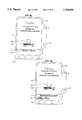
- FIG. 1is a perspective view of an infusion pump
- FIG. 2is a perspective view of an alternative infusion pump
- FIG. 3is an elevational view of the infusion pump of FIG. 1, showing the detail of the pump face;
- FIG. 4is a detailed view of the display area of the infusion pump of FIGS. 1 and 2;
- FIG. 5is an elevational view of the rear of the infusion pump of FIG. 1;
- FIGS. 6a to 10bshow the use interaction with the infusion pump of FIGS. 1 and 2;
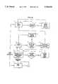
- FIG. 11is a block diagram of a battery gauge circuit constructed in accordance with the principles of the present invention.
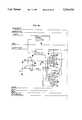
- FIG. 12(12a, 12b and 12c) is a schematic diagram of a battery gauge circuit constructed in accordance with the principles of the present invention.
- FIG. 13is a flow chart of a battery-monitoring process constructed in accordance with the principles of the present invention.
- FIG. 14is a flow chart of a battery life process constructed in accordance with the principles of the present invention.
- FIG. 15is a flow chart a of remaining time process constructed in accordance with the principles of the present invention.
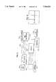
- an intravenous fluid infusion pumpis referred to generally as 10.
- the pump 10is clamped onto a standard IV pole 12.
- the IV pole 12typically includes at its lower periphery wheels which allow the IV pole, pump and any additional medical devices supported thereon some level of mobility so the patient can be moved.
- the pump 10includes a main body portion 14 and at least one pump module portion 16. In the embodiment depicted and described herein, two pump module portions 16 are provided. However, use of any number of pumping modules is contemplated depending on the requirements of the pump user. For example, FIG. 2 shows an infusion pump having four pumping modules 16.
- the main body 14further includes a liquid crystal display (LCD) area 23 which conveys information about the pump to the user and provides for user interface with the pump, as described in more detail below.
- the main body 14includes data-entry keys 25.
- the pump module 16includes a tube-loading channel 27 and a display area 29 with a microprocessor. In a preferred embodiment, this microprocessor is a 68HC11 available from Motorola, Schaumburg, Ill.
- the main body portion 14includes a slave microprocessor which is a slave to a master microprocessor.
- the slave microprocessorfurther includes an analog-to-digital converter (A/D converter).
- A/D converteranalog-to-digital converter
- the master microprocessoris a 80C186EB available from Intel Corporation, Santa Clara, Calif. and the slave microprocessor is a 80C552 available from Philips Semiconductors, Sunnyvale, Calif.
- the slave microprocessorincludes software in read-only memory (ROM) which drives the monitoring functions described below.
- FIG. 3an elevational view showing the detail of the face of the infusion pump 10 is seen.
- a scroll-up arrow key 31 and a scroll-down arrow key 33are used to select programming fields or actions within the display area 23.
- Contained beneath the display area 23are a plurality of arrow keys 36 which are used to interact with selection alternatives in the display area 23. Because these arrow keys 36 are used in conjunction with the particular function displayed in the display area 23, these arrow keys 36 are referred to as "soft keys.”
- the display area 23includes four display portions. Located at the top portion of the display area is the status display 38.
- the status display 38gives the status of the pump infusion.
- the status display 38also identifies alert, alarm, and failure conditions.
- Contained at the lower portion of the display area 23is the prompt display.
- the prompt displayincludes a prompt line 41 which provides prompts or instructions for the user.
- a soft key area 40is further provided which contains labels for the plurality of soft keys located beneath the display area 23. Thus, by following the prompts and making selections in accordance with the labels applied to the soft keys, the user can interface with the display screen.
- the middle portion 42 of the display area 23is used for making infusion selections, programming, and displaying operating or running conditions of the pump infusion.
- the main body 14further includes a plurality of function keys 44.
- the function keys 44include dedicated keys 46 which include user interface keys as well as a numeric key pad 50. Included in the numeric key pad 50 are the numbers zero through nine, and a decimal point key. These numeric and decimal point keys are used to enter programming values into the highlighted field in the display area 23, an example of which is seen in FIG. 4.
- the numeric key pad 50further includes a clear key 53 which is used to clear values from the highlighted field. As a safety feature against inadvertent clearing of values from the highlighted field, if the clear key 53 is again pressed after the highlighted field has been cleared, the content of the field is restored to the last value stored in the master microprocessor.
- the dedicated function keys 44include a main-display function key 55.
- the main-display function key 55is used to return the display area 23 to the initial or main display from any point in the user interaction.
- the volume-history function key 57is used to display the volume history screen.
- the silence function key 59silences pump alarms and pump alerts for a predetermined period, such as two minutes in the preferred embodiment.
- the back-light function key 61serves one purpose when the pump 10 is plugged into an electrical outlet, and a related but second purpose when the pump 10 is on auxiliary battery power. When plugged into an electrical outlet, the back-light function key 61 turns the display back lights on and off. When on auxiliary battery power, the back-light function key 61 illuminates the display back lights, but in order to conserve power the back lights do not remain on after a predetermined period.
- the action keysinclude an on/off charge key 63.
- the on/off charge key 63powers the infusion pump 10 on and off. When the pump 10 is infusing, pressing the on/off charge key 63 will provide a system override to stop the infusion.
- the action keysfurther include a start key 65. If all of the required programming values have been entered during the programming mode, the start key 65 initiates the infusion. Following an alarm notification, once the alarm condition is resolved the start key 65 cancels the alarm notification and restarts the infusion.
- the action keysfurther include a rate key 68, which is used to select the rate values, and a volume key 70, which is used to select the volume parameters when the infusion pump 10 is programmed for an infusion.
- the electronic-plug icon 72indicates when the infusion pump 10 is plugged into an electrical outlet.
- the electronic-plug icon 72also indicates that the auxiliary battery is being charged from the electrical power provided by the electrical outlet.
- a battery icon 74is further provided, which is lit when the pump 10 is operating on auxiliary battery power, as described in detail below.
- At least one pump module 16is located beneath the main body 14 of the pump 10.
- the pump module 16includes a tube loading channel 27 into which a standard IV tube 76 is loaded into the pump 10.
- the pump module 16includes an automatic tube-loading feature. Contained within the tube-loading channel 27 is a keyed slot 78 adapted to receive a slide clamp 80 contained on the IV tube 76.
- the pump module 16includes a free-flow prevention feature.
- the pump module 16contains several safety features. Initially, the slide clamp 80 is keyed such that it only fits into the keyed slot 78 in the proper orientation. Additionally, beneath the tube-loading channel 27, a fluid flow arrow 81 is provided to instruct the user as to the proper direction of fluid flow in the IV tube 76. Still further, on the left side of the pump module 16 an intravenous solution bag icon 83 is provided. This reminds the user that the end of the IV tube 76 that connects to the solution bag is to be directed to the left side of the tube-loading channel 27. Still further, on the right side of the pump module 16 is a patient icon 85. This icon 85 is used to remind the user that the end of the IV tube 76 that connects to the patient is to be directed to the right side of the tube-loading channel 27.
- the pump module display area 29further includes a character display area.
- a character display areaIn the embodiment depicted herein, an eight-character display area is provided.
- the display areais used to prompt or instruct the user during specific pump interaction operations.
- the displayalso is used during an alarm or alert condition to identify the particular condition.
- the displayis used during infusion to provide an indication of the status of the infusion.
- the character display areaContained beneath the character display area are three light-emitting diode (LED) status indicators.
- the firstis a green LED 87 which indicates when the pump 10 is infusing.
- the secondis a yellow LED 89 which indicates when the pump 10 is in an alert condition.
- the yellow LED 89remains continuously lit during an alert condition, provided there are no active alarms.
- the thirdis a red LED 91 which indicates when the pump 10 is in an alarm condition.
- the red LED 91flashes on and off during an alarm condition and remains lit continuously during a failure condition. If the infusion pump 10 is running on auxiliary battery power, the alert or alarm display will flash on and off in order to conserve battery power.
- the pump module 16also includes an open action key 94 and a stop-action key 96.
- the open action key 94opens the loading mechanism so that an IV tube can be loaded into the tube-loading channel 27.
- the open action key 94opens the loading mechanism to allow removal of the IV tube.
- the stop-action key 96provides a system override to stop any active infusion.
- the infusion pump 10includes a grounded power cord 98 for plugging the pump 10 into a wall outlet to provide standard AC to power the infusion pump 10 and to recharge the auxiliary battery.
- the devicefurther includes a mounting clamp 100 which is used to mount the pump 10 onto an IV pole 12.
- An audio speaker grill 102is provided over an audio speaker which is used to generate alert and alarm condition audio tones.
- a communications port 104is provided to allow the pump 10 to connect and communicate with a computer.
- the communications port 104also can be used to communicate the nurse call signal to a computer located at a nurse station in a hospital.
- an RS 232 compatible interfaceis provided for external communications.
- a DC receptacle 107is further provided.
- the DC receptacle 107enables the pump 10 to be connected to external DC power sources, such as for example, the 12-volt power source provided in most U.S. vehicles, to enable the pump 10 to be used with an ambulatory patient.
- the rear of the infusion pump 10further includes fuse compartments 109 which contain electronic fuses as known in the art, an audio speaker volume control 111, and an LED contrast adjustment 113 for the main display.
- a panel lock button 116is further provided. Enabling the panel lock button 116 disables the front panel keys to prevent inadvertent reprogramming as well as deliberate tampering with the pump 10.
- each pump module 16Contained on the side of each pump module 16 is a manual-tube release knob 118.
- This knob 118provides a manual override of the automatic tube-loading and unloading feature in the pump module 16. This allows the user to manually release the tubing from the pump 10.
- a drop-sensor port 120Further provided on each pump module 16 is a drop-sensor port 120. This port 120 allows for connection to the pump 10 of an optional drop sensor, which is used in conjunction with a standard drip chamber.
- the user interaction with the infusion pump 10is described. As previously discussed, the user interaction is principally conducted through the pump display area 23, including the scroll up and scroll down arrow keys 31, 33 contained on the side and the soft keys 36 displayed underneath the display area 23.
- the pump self-diagnostic testsbegin.
- the main display area 23initially is lit, then goes dark, while the pump module display 29 illuminates each of the character positions.
- the LEDsare lit and the audible speaker is activated, followed by the sounding of the back-up buzzer.
- This procedureenables the user to check for dark spots or lines on the display when the screen is lit, check for light spots or lines on the display when the screen is dark, ensure that the pump module display characters are appropriately lit, ensure that all of the LEDs are in working order, and hear that the audible speaker and back-up buzzer tone are active.
- the screendisplays the pump identification screen seen in FIG. 6(a).
- This screenincludes a battery icon 122.
- the battery icon 122includes a gauge 124 which graphically demonstrates the amount of amp hours remaining in the rechargeable auxiliary battery.
- the prompt line 41identifies that the pump self-diagnostic tests are proceeding and instructs the user to wait until the self-diagnostic tests are over.
- the prompt line 41instructs the user that the pump 10 is ready to continue into the programming mode.
- several soft keys 36are made available, depending on the configuration options chosen by the user. For example, in the embodiment depicted in FIG. 6(b), a soft key labeled "change PersonalityTM" is present which enables the user to enter a programming mode to change the previously selected set of configuration parameters. Additionally, a soft key labeled "new patient” is present, indicating that information from a previous program is still retained in the memory. Pressing the "new patient” soft key will clear the programming memory and volume history from this previous patient. As instructed in the prompt line 41, pressing the main display key 55 advances the display area 23 to the main display screen.
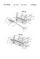
- the userPrior to programming the infusion pump 10, the user is instructed to load an IV tube 76 into the pump module 16. Referring now to FIG. 7, the loading of the IV tube 76 into the automated tube-loading slot 27 in the pump module 16 is described.
- the open key 94is pressed, which causes the automatic tube-loading mechanism to open.
- the userpositions the on/off slide clamp 80 into the keyed slot 78, which helps assure the proper orientation of the IV tube 76. Pulling the IV tube 76 taut, as seen in FIG. 7(b), the user slides the IV tube 76 into and along the tube-loading channel 27.
- the pump 10detects the presence of the IV tube 76, the pump 10 automatically loads the IV tube 76 into the proper position in the pump drive mechanism. If the IV tube 76 is not loaded in a given predetermined time period after the open key 94 has been pressed, the automatic tube-loading mechanism will close to assure that an inadvertent loading of an improper IV tube does not occur. Additionally, when off, pressing the open key powers on the infusion pump 10 so that the IV tube 76 can be loaded into the device.
- the main display screenincludes the stop icon 126 which indicates that the pump 10 is not infusing.
- the soft keys 36include an "option” key, a "primary” key, and a “piggyback” key.
- a stop icon 128 contained above the "primary” soft keyindicates the default infusion.
- the display screenprompt instructs the user to press the "primary” soft key or "piggyback" soft key to view the programming mode for those two infusions.
- the rate key 68is pressed, which changes the display to the rate-volume programming screen with the rate field highlighted, as seen in FIG. 6(d). If neither the "primary" soft key nor the "piggyback" soft key is pressed, the programming mode assumes the default infusion is to be programmed.
- the rate-volume programming screen prompt line 41instructs the user to enter the rate or press change mode, while the soft key options include the "change mode” key and the "piggyback" key.
- pressing the clear key 53clears the incorrect value so that the correct value can be programmed using the numeric key pad 50.
- the start key 65is pressed. If the programmed values exceed an allowable range preprogrammed into the master microprocessor based on the particular set of configuration parameters chosen by the user, an out-of-range alarm will be activated upon pressing the start key 65.
- the display area 23When infusing, the display area 23 will show as a droplet icon an animated drop of water to indicate that the pump 10 is operational.
- the program rate of delivery, the volume of fluid remaining to be delivered, and/or the time remaining to deliver the remaining volumewill be displayed.
- the stop key 96is pressed.
- the droplet iconwill be replaced with the stop icon on the main display and the pump LED will no longer be illuminated.
- the start key 65is pressed.
- a channel stop alertwill sound.
- the pump 10also can be stopped if any alarm condition occurs or if the on/off charge key 63 is pressed while running.
- a piggyback infusionis stopped by closing the slide clamp 80 on the secondary infusion IV tube and pressing the stop key 96.
- the "primary" soft keyis pressed to change the operation mode of the pump 10, followed by the pressing of the start key 65 to begin the primary infusion.
- the pump 10will automatically enter a keep-vein-open (KVO) alert mode. During this alert mode, the pump 10 will continue infusing at the lesser of a preprogrammed KVO rate or at the programmed rate. To exit the KVO alert mode, the stop key 96 is pressed. The pump 10 can then be programmed for the next infusion, or the pump 10 can be powered off.
- KVOkeep-vein-open
- the open key 94is pressed.
- the pump module 16automatically closes the slide clamp 80 and opens the tube-loading channel 27 to allow removal of the IV tube 76.
- the auto load mechanismwill close.
- the mechanismwill automatically close.
- a pop-up windowwhich displays an options window if the "options" soft key is pressed from the main display.
- the options menuincludes a flow check feature, a current PersonalityTM view feature, the selection of the downstream occlusion values, the battery charge level feature, and the configuration/service feature.
- the userhighlights the feature to be viewed using the scroll-up and scroll-down arrow keys 31, 33.
- the current PersonalityTM view featureallows a quick review of the current set of configuration parameters.
- the battery charge level on the options menuallows the user to access information regarding the battery charge level of the auxiliary battery.
- the battery charge icon 122is displayed in the main display area.
- the prompt line 41instructs the user how to exit the battery charge level option.
- a "done" soft keyis provided to exit the battery charge level display.
- the present inventionalso provides several troubleshooting alert, alarm and failure messages.
- alert messagesmay require a user intervention, but do not stop the infusion.
- Alarm conditionsautomatically stop the infusion and require immediate attention before infusion can be restarted.
- a device failureautomatically stops any infusion.
- An alarm conditionoverrides an existing alert condition while a failure overrides all alerts and alarms.
- An alert conditionlights the yellow alert LED 89 beneath the pump module display, and sounds the alert tone.
- the alert tonecan be silenced for a period of time, such as two minutes, by pressing the silence key 59.
- the alert conditionsinclude a battery low alert, which indicates that the auxiliary battery has less than a predetermined amount of infusion time left, as described in detail below. This alert occurs before the battery alarm condition occurs.
- the battery depleted alarmindicates that the auxiliary battery charge has diminished below the level necessary to continue infusion, as described in detail below. To reset the battery depleted alarm, the infusion pump 10 must be plugged into an AC supply.
- the configuration/service function of the option menu seen in FIG. 8(a)is selected.
- a password entry screen seen in FIG. 9(a)appears.
- the passwordensures that only proper hospital personnel access the configuration/service routine.
- the prompt line 41directs entry of the password.
- the authorized personnelenters a numeral password in order to proceed in the configuration/service routine.
- the password entry screenincludes a reference listing of the software version in the infusion pump 10. A "cancel" soft key is provided to exit the routine.
- a configuration/service menu screenas seen in FIG. 9(b) appears.
- the optionsinclude PersonalityTM configuration utility, device configuration utility, event history, service features, device configuration transfer, download configuration, time set and date set.
- a messageappears giving the particular components of an option.
- the PersonalityTM configuration utilityincludes as components a PersonalityTM list, infusion modes and features, infusion limit alerts and alarms, drop sensors, and label library.
- the infusion limits, alerts and alarmsare accessed from the PersonalityTM configuration menu, seen in FIG. 9(c). Upon selection, the infusion limits, alerts and alarms menu seen in FIG. 9(d) is displayed.
- the settings in the PersonalityTM configuration menuapply to the infusion pump 10 as a whole and are not programmable for separate channels.
- the infusion pumpfurther includes service features which are accessible from the configuration/service menu.
- the service features menu seen in FIG. 10(a)is displayed.
- the slave microprocessorkeeps track of a plurality of time periods related to battery operation. In the preferred embodiment, two parameters are tracked, including the total amount of time the infusion pump 10 is on and not plugged in, and the total amount of time the infusion pump is on.
- the battery information screen seen in FIG. 10(b)includes the battery charge icon 122, "done" and "new battery” soft keys, and the parameters. When a new battery is installed, the time parameters are cleared.
- the service featuresalso include sensor calibration, which displays information related to the installation or replacement of certain infusion pump components, and manufacturing tests, which are used in the manufacturing process to calibrate infusion pump components.
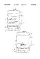
- a block diagram of the battery gauge circuitis seen.
- a precise reference voltage 200is provided.
- the reference voltageis 5 volts.
- the reference voltage 200establishes the bias conditions required by the true RMS converter.
- the reference voltage 200also provides the slave microprocessor A/D converter 202 with the reference voltage.
- the precise reference voltage 200is input into a buffer and level shifter 204.
- the buffer and level shifter 204derives two reference voltages: a high-reference voltage 206 and a low-reference voltage 208.
- the high-reference voltage 206is 5.7 volts and the low reference voltage 208 is 2.5 volts.
- the high-reference voltage 206 and the low-reference voltage 208are input into a true RMS converter 210.
- the battery gauge circuitfurther includes an analog electronic switch 212 which determines which of the four voltage/current ranges 214 is being measured.
- the switch 212is an electronic multiplexer.
- the switch 212is controlled by a control circuit 216 which also powers the gauge circuit on and off.
- the switch 212sends to the true RMS converter 210 the selected signal.
- the true RMS outputis conditioned by a conditioning circuit 218 prior to use as input into the A/D converter 202 of the slave microprocessor for analysis as described below.
- the battery positiveis input into a DC switch QD1 which, in a preferred embodiment, is an SI9942DY dual transistor available from Siliconix, Santa Clara, Calif.
- the S19942DY dual transistorhas internal PFET and NFET transistors.
- the battery positiveis input into the SP pin.
- the battery negativeis set to ground via precision sensing resistor R2.
- DC switch QD1is normally pulled up by resistor R1 connected between the battery positive terminal and the gate input of DC switch QD1.
- the GP input of DC switch QD1must be pulled low.
- the battery gauge circuitfurther includes a precision reference voltage regulator U1.
- the reference voltageis 5 volts and the reference voltage regulator U1 is an LT1021 DCS8-5 available from Linear Technology, Milpitas, Calif.
- the reference voltage regulator U1is an REF195GS available from Analog Devices, Norwood, Mass.
- the signalis applied to the V+ input of the voltage regulator U1 through resistor R4. Resistor R4 reduces power consumption and acts as short-circuit protection for the battery.
- a resistor R5is provided if the reference voltage regulator includes a shut-down feature, such as in the REF195GS.
- the precise reference voltageis input into the positive input of operational amplifier Q1 and is input via resistor R6 into the positive input of operational amplifier Q2.
- the precise reference voltageis further provided as a reference voltage to the slave microprocessor to be utilized as the A/D reference voltage.
- Operational amplifier Q1provides as output a precise high reference which, in a preferred embodiment, is 5.7 volts.
- Operational amplifier Q2provides as output a precise low reference which, in a preferred embodiment, is 2.5 volts.
- the supply voltage for operational amplifiers Q1, Q2, Q6 and Q7is derived from the junction of resistors R4 and R5.
- the battery gauge circuitfurther includes a true RMS converter U2.
- the true RMS converter U2is an AD736JR available from Analog Devices, Norwood, Mass.
- the high referenceis applied to the +VS input of the RMS converter U2.
- the low referenceis applied to the CC input and the COM input of the RMS converter U2.
- Resistors R10 and R11establish an offset bias to allow the RMS connector to perform the conversion from AC and DC input to true RMS DC output.
- Capacitor C4is used for average mode filtering while additional capacitor C5 is used for additional true RMS filtering.
- the drain of field-effect-transistor FET1is connected to capacitor C5 while the source is attached to ground.
- the gate of field-effect-transistor FET1is connected to an input which is high for true RMS and low for average as applied by a slave microprocessor.
- the signal at the gate of field-effect-transistor FET1is high, the transistor conducts from drain to source to allow capacitor C5 to effect the true RMS filtering.
- Capacitor C6is of a relatively small value and limits any high frequency interference noise present in the area from adversely affecting the performance of the circuit.
- the battery gauge circuitfurther includes an analog switch U3, which selects the four inputs to the circuit.
- the analog switch U3is an MAX309CSE available from Maxim Corp., Sunnyvale, Calif.
- the analog switchconsists of two sections U3A and U3B.
- the four inputsare the high-voltage range, low-voltage range, high-current range and low-current range.
- the high-voltage rangeis derived from a voltage divider consisting of resistor R12 and resistor R13 off the battery, as derived from the output of DC switch QD1, which is input into the 4 and 13 pins of analog switch U3.
- the low-voltage rangeis derived from the voltage divider made up of resistors R12, R13, through adjusting resistor R14, input into the 5 and 12 pins of analog switch U3.
- the four selectionsare unique and no leakage or cross talk occurs between the four selections.
- the low current indicationis supplied from operational amplifier Q3, the output of which is input into the 6 and 11 pins of analog switch U3.
- Resistor R15 and resistor R16set the offset of operational amplifier Q3, while resistor R17 and resistor R18 set the gain of operational amplifier Q3.
- Resistor R16also may include a second rheostat VR2 for setting the output to mid range.
- Capacitor C7limits any high frequency interfering noise present in the area from adversely affecting the circuit.
- the source voltage for this driveris obtained from the difference in voltage across resistor R2.
- the high current rangeis set by resistor R20 and is input into the 7 and 10 pins of analog switch U3 and also derives its source voltage from the difference in voltage across resistor R2.
- a coarse voltage signalalso is supplied to the slave microprocessor so that measurements of battery voltage can be made when the high-voltage or low-voltage measurements are not being made and acts as a second check on the battery gauge.
- the coarse voltage signalis output from operational amplifier Q4 the positive input of which is derived from a voltage divider made up of resistors R12, R13. This voltage is used by the slave microprocessor for detecting pump alarms due to voltage decreases.
- the voltage supplied to resistor R12is derived from pins 5 and 6 of switch QD1.
- the true RMS output from the RMS converter U2is conditioned by operational amplifier Q6 and operational amplifier Q7 prior to input into the A/D converter.
- Operational amplifier Q6acts as a zero-impedance feed into the resistor gain network made up of resistor R21 and resistor R22.
- a rheostat VR1is adjusted for the midrange voltage.
- Resistor R23 and resistor R24refine the range of adjustment of rheostat VR1.
- Capacitor C8limits noise present in the area from adversely affecting the circuit.
- Capacitor C9stabilizes operational amplifier Q6.
- the conditioned true RMS signalis supplied to the A/D converter through resistor R25. After rheostat VR1 is adjusted, rheostat VR2 is adjusted for the mid-range voltage when the low current range is selected.
- the battery gauge circuitprovides input to the slave microprocessor so that the battery-monitoring process portion of the battery gauge can occur.
- the battery-monitoring processhas four critical states: Battery Alert; Battery Alarm; Battery Depleted; and Battery Overcharge.
- a Battery Alertis generated when less than a predetermined time is left until the Alarm is generated. In a preferred embodiment, this predetermined time is 30 minutes.
- a Battery Alarmoccurs when the battery voltage falls below a critically determined value. In a preferred embodiment, this critical value is 10.8 volts.
- the Battery Deplete alarmis generated when the battery falls below a battery-depleted value. In a preferred embodiment, the battery-depleted value is either 10.4 volts or 0.25 amp hours remaining.
- the Battery Overchargeoccurs when the battery has overcharged, as described in detail below.
- the auxiliary batteryis an NP2-12 available from Yuasa Battery America, Santa Fe Springs, Calif.
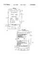
- step 1the Charge State
- the battery gaugeis monitoring the auxiliary battery, which is charging because it is connected to a wall outlet.
- the battery gaugewill sample inputs read from the auxiliary battery.
- step 2the gauge, having read these inputs, compares the total time elapsed since the battery began charging with the time required to fully charge the battery. In a preferred embodiment, the time required to charge the battery from a full depletion is fifteen hours. This figure would be adjusted for batteries of different capacities or for batteries which have not completed a full discharge cycle prior to entering the charging state.
- Step 2also determines if the current drawn by the battery is less than a minimum amperage. In a preferred embodiment, this minimum amperage is 4 ma. If either the time charging or the current drawn indicates the battery has been fully charged, the maximum amp hour capacity for the battery will be calculated in step 3.
- the battery capacityis recalculated by interpolating between a minimum and a maximum amp hour capacity for the battery based on the number of discharge cycles.
- the maximum capacityis 1.9 amp hours (for a new battery) and the minimum is 1.3 amp hours.
- the interpolationis done on a linear basis with a maximum of 150 discharge cycles representing 1.3 amp hours.
- the interpolated valueis then averaged with the actual number of amp hours that have been calculated throughout the charging cycle based on current into the battery, as shown in FIG. 15 and described below.
- the battery gaugewill enter step 4 (the Fully Charged State). If the battery has not been fully charged, the remaining amp hours in the battery will be calculated in step 6, as shown in FIG. 15 and discussed below. When the remaining amp hours have been calculated, the battery gauge will return to step 1.
- the battery gaugewill periodically monitor to detect an overcharge condition.
- an overcharge conditionexists if the current decreases below 50 ma and then rises above 50 ma or if the charging voltage of the battery exceeds 14.1 volts. If an overcharge condition is detected in step 5, the battery gauge will set a service alert in step 6, the alert will be displayed or deferred until the next power on of the infusion pump.
- the inputsare received from the A/D converter of the slave microprocessor as count readings.
- the inputsinclude low current, high current, low voltage, high voltage and coarse voltage.
- the count read for the various inputsis converted by the microprocessor into a voltage or milliamperage reading which may be displayed or used for further calculations.
- the maximum count valueis a distinguished input which reflects any error in monitoring the battery and which is not converted.
- the high currentis initially sampled. If this value is in a predetermined low-current value, the value is discarded and the low current is subsequently used in its place.
- the low-voltageis sampled. If the coarse voltage is less than a predetermined low voltage range, the low battery gauge voltage is selected; otherwise the high voltage is sampled. In the preferred embodiment's steady state, the use of either high or low inputs may be changed as the sampled values cross the thresholds.
- the low-current valueis in the ⁇ 370 ma range and the low voltage is less than 13.05 volts.
- step 7the Drain State
- the battery gaugewill be transferred to step 7 (the Drain State) upon disconnection from the wall outlet while the infusion pump remains in power-on mode. If in the power-off mode when the infusion pump is disconnected from the wall outlet, the number of remaining amp hours, the number of discharge cycles and the date are stored for later use, but no new actions are taken until the infusion pump is powered on. When the infusion pump is powered on again, the amp hours remaining will be discounted by a percentage for the time the battery has been powered off. In a preferred embodiment, the discount is 2% per month.
- the battery gaugeleaves step 7 when the infusion pump is reconnected to a wall outlet. Upon pump reconnection to a wall outlet, the battery gauge recomputes the number of discharge cycles the battery has passed through. This is done in step 8 by adding the number of quarter-discharge cycles (rounded down to the next lowest quarter-discharge) to the previously stored number of discharge cycles. The new total number of discharges is compared in step 9 to a maximum number of discharges. In a preferred embodiment, this number of discharges is 150. If the new number of discharges exceeds this number, a service alert is issued in step 10. Whether or not such an alert is issued, the battery gauge then enters step 1 (the Charge State), the effect of which is described above.
- step 7the battery gauge periodically monitors the remaining life of the battery.
- the steps it takesare shown in FIG. 14.
- the first step 11samples the coarse voltage and compares it with an absolute minimum below which damage will be done to the battery. In a preferred embodiment, this voltage is 10.4 volts. If the coarse voltage is below this threshold, the device is shut down in step 12. If the coarse voltage is above the absolute minimum threshold, the coarse voltage is compared with a higher voltage threshold in step 13. In a preferred embodiment, the threshold is 10.8 volts. If the coarse voltage is below this higher threshold, an alarm is activated in step 14. This alarm is reset only upon reconnection of the infusion pump to the wall outlet. If the alarm is reset, the battery gauge then recalculates the remaining amp hours in the battery, as shown in FIG. 15 described below. The battery gauge then returns to the Drain State, shown in FIG. 13, step 7.
- the battery gaugeIf the coarse voltage thresholds in steps 11 and 13 are not crossed, the battery gauge then recalculates the remaining amp hours in the battery, as shown in FIG. 15 described below. With this information, in step 15, the battery gauge calculates the remaining minutes left in the battery.
- step 16the remaining time is compared to a minimum threshold time remaining. In a preferred embodiment, this minimum time remaining is thirty minutes. If the remaining time as calculated in steps 15 and 16 is less than the minimum threshold time remaining, in step 17, the battery gauge registers an alert that the battery is low. This alert is reset only upon reconnection of the infusion pump to the wall outlet.
- the time remainingis recalculated in step 18 using true RMS voltages sampled over time. This compensates for the effect of spaced, unequal impulses going into the infusion pump, which can cause a single voltage reading to not accurately to reflect the battery usage.
- the inventionextrapolates the time remaining based on a series of true RMS voltage samples over a period of time.
- the voltage samplesare accumulated to cover a period of six minutes. Six voltage values are stored, each of which represents the average of 10 true RMS voltage samples taken at six-second intervals.
- the extrapolationis done linearly, although in an alternative preferred embodiment a higher-level extrapolation can be made, either exactly or by adjusting the linearly computed time remaining according to a known factor reflecting the non-linearity of the impulse behavior.
- the slope and interceptare calculated according to the following formulas:
- Ais the intercept of voltage at time 0, i.e., six minutes before present
- ⁇ XYis the summation of each voltage reading (Y) multiplied by its time position (X) (time positions are measured from 1 to 6, with time 6 being the most recent);
- Xis the average of all time position values, or six in the preferred embodiment.
- Yis the average of all voltage values, or six in the preferred embodiment.
- Tis the time left to reach any voltage used in the formula, in minutes.
- the voltage used in this formulais 10.4 volts.
- the battery gaugeagain compares the time with a minimum threshold time remaining. In a preferred embodiment, this minimum threshold time remaining is 30 minutes. If the remaining time as calculated in step 19 is less than the minimum threshold time remaining, then in step 17, the battery gauge registers an alert that the battery is low. This alert is reset only upon reconnection of the infusion pump to a wall outlet. In a preferred embodiment, this extrapolation can necessarily only take place once the battery has been in a drain state for six minutes. Prior to that time, the battery gauge will issue an alert if less than 11.8 volts remain in the battery, as determined by the coarse voltage sample.
- step 7Regardless of whether the battery gauge registers an alert in step 17 or the comparison in step 19 determines that there is enough time left in the battery, the battery gauge returns to the Drain State, as shown in FIG. 13, step 7.
- step 20the battery gauge samples the true current through the battery and subtracts the previously sampled true current and stores the result as delta true current. Depending on the time between samples, which in a preferred embodiment is six seconds, the battery gauge will calculate the change in current over a standard unit of time in step 21.
- step 22the battery gauge determines if the battery is in charging state. In a preferred embodiment, the battery will always draw a small amount of current, less than or equal to 4 ma, even if fully charged. Therefore, the battery will be considered to be charging when the battery is drawing more than 4 ma. If the current readings and therefore current over time readings are negative, the battery is draining. The battery should not be draining if the battery is connected to the wall outlet. In a preferred embodiment, a signal is set when the power supply is connected. If a battery drain is occurring in this state, then a failure is issued.
- step 24which is reached only if the battery is charging, the change in current over time is discounted by a battery-dependent factor based on the number of partial discharges that the battery has experienced.
- the discountis a percentage from 0-15% that is linearly interpolated based on the number of discharge cycles that the battery has gone through.
- step 26the battery gauge adds the change over time to the stored amp hour value, completing the process.
Landscapes
- General Physics & Mathematics (AREA)
- Physics & Mathematics (AREA)
- Health & Medical Sciences (AREA)
- Public Health (AREA)
- Engineering & Computer Science (AREA)
- Heart & Thoracic Surgery (AREA)
- Hematology (AREA)
- Life Sciences & Earth Sciences (AREA)
- Animal Behavior & Ethology (AREA)
- General Health & Medical Sciences (AREA)
- Anesthesiology (AREA)
- Veterinary Medicine (AREA)
- Biomedical Technology (AREA)
- Vascular Medicine (AREA)
- Infusion, Injection, And Reservoir Apparatuses (AREA)
- Measurement Of Current Or Voltage (AREA)
- Secondary Cells (AREA)
- Hybrid Cells (AREA)
- Battery Electrode And Active Subsutance (AREA)
- Tests Of Electric Status Of Batteries (AREA)
Abstract
Description
B=((ΣXY)-(n *Y))((ΣX.sup.2)-(n*X))
and
A=Y(B*X)
B=((ΣXY)-(21*Y))/17.5
and
A=Y-(B * 3.5)
T=((V-A)/B)-6.
Claims (15)
B=(ΣXY)-(n*Y))/((ΣX.sup.2)-(n*X))
A=Y-(B*X)
and
T=((V-A)/B)-m
Priority Applications (15)
| Application Number | Priority Date | Filing Date | Title |
|---|---|---|---|
| US08/630,359US5764034A (en) | 1996-04-10 | 1996-04-10 | Battery gauge for a battery operated infusion pump |
| GB9614161AGB2312049B (en) | 1996-04-10 | 1996-07-05 | Battery gauge |
| CA002223841ACA2223841C (en) | 1996-04-10 | 1997-01-23 | Battery gauge |
| AU17527/97AAU710286B2 (en) | 1996-04-10 | 1997-01-23 | Battery gauge |
| NZ329318ANZ329318A (en) | 1996-04-10 | 1997-01-23 | Battery gauge monitors voltage and current flowing from battery |
| JP53616997AJP2002506514A (en) | 1996-04-10 | 1997-01-23 | Battery gauge |
| PCT/US1997/001017WO1997038322A1 (en) | 1996-04-10 | 1997-01-23 | Battery gauge |
| KR1019970709249AKR100376076B1 (en) | 1996-04-10 | 1997-01-23 | Battery Gauge |
| EP97904839AEP0832439A1 (en) | 1996-04-10 | 1997-01-23 | Battery gauge |
| TW086102976ATW317665B (en) | 1996-04-10 | 1997-03-11 | |
| HK98101116.0AHK1002291B (en) | 1996-04-10 | 1998-02-12 | Battery gauge |
| JP2002368989AJP2003220137A (en) | 1996-04-10 | 2002-12-19 | Battery gauge |
| JP2005347188AJP2006116336A (en) | 1996-04-10 | 2005-11-30 | Battery gauge |
| JP2006336435AJP2007098155A (en) | 1996-04-10 | 2006-12-13 | Battery gauge |
| JP2009120351AJP2009213906A (en) | 1996-04-10 | 2009-05-18 | Battery gauge |
Applications Claiming Priority (1)
| Application Number | Priority Date | Filing Date | Title |
|---|---|---|---|
| US08/630,359US5764034A (en) | 1996-04-10 | 1996-04-10 | Battery gauge for a battery operated infusion pump |
Publications (1)
| Publication Number | Publication Date |
|---|---|
| US5764034Atrue US5764034A (en) | 1998-06-09 |
Family
ID=24526854
Family Applications (1)
| Application Number | Title | Priority Date | Filing Date |
|---|---|---|---|
| US08/630,359Expired - LifetimeUS5764034A (en) | 1996-04-10 | 1996-04-10 | Battery gauge for a battery operated infusion pump |
Country Status (10)
| Country | Link |
|---|---|
| US (1) | US5764034A (en) |
| EP (1) | EP0832439A1 (en) |
| JP (5) | JP2002506514A (en) |
| KR (1) | KR100376076B1 (en) |
| AU (1) | AU710286B2 (en) |
| CA (1) | CA2223841C (en) |
| GB (1) | GB2312049B (en) |
| NZ (1) | NZ329318A (en) |
| TW (1) | TW317665B (en) |
| WO (1) | WO1997038322A1 (en) |
Cited By (130)
| Publication number | Priority date | Publication date | Assignee | Title |
|---|---|---|---|---|
| US5914609A (en)* | 1996-11-08 | 1999-06-22 | Bitrode Corporation | Method and system for battery charging and testing with semi-automatic calibration |
| US5994876A (en)* | 1997-10-09 | 1999-11-30 | Abbott Laboratories | Battery capacity measurement circuit |
| US6070761A (en) | 1997-08-22 | 2000-06-06 | Deka Products Limited Partnership | Vial loading method and apparatus for intelligent admixture and delivery of intravenous drugs |
| WO2001065657A1 (en)* | 2000-02-29 | 2001-09-07 | Alaris Medical Systems, Inc. | Power management system |
| US6351099B2 (en)* | 1999-07-22 | 2002-02-26 | Dallas Semiconductor Corporation | Battery monitoring system with integrated battery holder |
| US6429625B1 (en)* | 2001-05-18 | 2002-08-06 | Palm, Inc. | Method and apparatus for indicating battery charge status |
| US6625552B1 (en) | 1999-11-05 | 2003-09-23 | General Electric Company | Battery fuel gauge for display in battery-powered equipment |
| US6760618B1 (en)* | 1999-09-20 | 2004-07-06 | Hisamitsu Pharmaceutical Co., Inc. | Iontophoresis system |
| US6771172B1 (en)* | 1999-11-11 | 2004-08-03 | General Electric Company | Portable patient monitor with alarm light integrated into handle |
| US20040199146A1 (en)* | 2003-04-07 | 2004-10-07 | Rogers Charles R. | System and method for monitoring power source longevity of an implantable medical device |
| GB2402224A (en)* | 2003-05-29 | 2004-12-01 | Yuasa Battery | Battery life monitor and battery state of charge monitor |
| US20050113887A1 (en)* | 2003-10-02 | 2005-05-26 | Medtronic, Inc. | User interface for external charger for implantable medical device |
| US20050251760A1 (en)* | 2004-05-07 | 2005-11-10 | Sony Corporation | Portable electronic device, display method, program, and graphical user interface thereof |
| US20060006842A1 (en)* | 2002-07-01 | 2006-01-12 | Igor Miskovic | System and method for power consumption management |
| US20060187072A1 (en)* | 2005-02-23 | 2006-08-24 | Eaglepicher Energy Products Corporation | Physical key to facilitate an inactive mode for a state-of-charge indicator within a battery |
| US20070098565A1 (en)* | 2005-11-01 | 2007-05-03 | Parsee Mehryar M | Infusion pump having function keys |
| US20070173762A1 (en)* | 2005-09-26 | 2007-07-26 | M2 Medical A/S | Operating an Infusion Pump System |
| US20080058712A1 (en)* | 2006-08-31 | 2008-03-06 | Plahey Kulwinder S | Peritoneal dialysis machine with dual voltage heater circuit and method of operation |
| US20080229819A1 (en)* | 2007-03-19 | 2008-09-25 | Wayne Water Systems, Inc./Scott Fetzer Company | Capacitive Sensor and Method and Apparatus for Controlling a Pump Using Same |
| US20080243079A1 (en)* | 2007-03-30 | 2008-10-02 | Nipro Diabetes Systems, Inc. | Rechargeable battery backup apparatus and method for insulin pump |
| US20090153058A1 (en)* | 2007-12-18 | 2009-06-18 | Hospira, Inc. | Infusion pump with configurable screen settings |
| US20090171289A1 (en)* | 2007-12-18 | 2009-07-02 | Hospira, Inc. | User interface improvements for medical devices |
| US20090273349A1 (en)* | 2008-04-30 | 2009-11-05 | Medtronic, Inc. | System and method for monitoring a power source of an implantable medical device |
| US20090297362A1 (en)* | 2008-05-27 | 2009-12-03 | Txam Pumps Llc | Electrical system for a pump |
| US20090312708A1 (en)* | 2005-04-27 | 2009-12-17 | Seiko Epson Corporation | Fluid transportation system and method of setting fluid ejection amount |
| US20110040252A1 (en)* | 2007-10-16 | 2011-02-17 | Peter Gravesen | Cannula Insertion Device and Related Methods |
| US20110046558A1 (en)* | 2009-08-18 | 2011-02-24 | Peter Gravesen | Medicine delivery device having detachable pressure sensing unit |
| US20110043357A1 (en)* | 2009-08-18 | 2011-02-24 | Greg Peatfield | Methods for detecting failure states in a medicine delivery device |
| US20110060281A1 (en)* | 2009-09-10 | 2011-03-10 | Roche Diagnostics International Ag | Medical Infusion Pump With Power Source Voltage Logging And Method For Logging A Power Source Voltage In A Medical Infusion Pump |
| US7935074B2 (en) | 2005-02-28 | 2011-05-03 | Fresenius Medical Care Holdings, Inc. | Cassette system for peritoneal dialysis machine |
| US20110110794A1 (en)* | 2009-11-12 | 2011-05-12 | Philip Mayleben | Sensors and methods and apparatus relating to same |
| US20110110792A1 (en)* | 2009-11-12 | 2011-05-12 | Joseph Kendall Mauro | Sensors and methods and apparatus relating to same |
| EP2390775A2 (en)* | 2010-05-25 | 2011-11-30 | NCR Corporation | Self adjusting kiosk display |
| US8105269B2 (en) | 2008-10-24 | 2012-01-31 | Baxter International Inc. | In situ tubing measurements for infusion pumps |
| US8115635B2 (en) | 2005-02-08 | 2012-02-14 | Abbott Diabetes Care Inc. | RF tag on test strips, test strip vials and boxes |
| US8137083B2 (en) | 2009-03-11 | 2012-03-20 | Baxter International Inc. | Infusion pump actuators, system and method for controlling medical fluid flowrate |
| US8142653B2 (en) | 2002-06-04 | 2012-03-27 | Fresenius Medical Care Deutschland Gmbh | Medical fluid cassettes and related systems |
| US8192401B2 (en) | 2009-03-20 | 2012-06-05 | Fresenius Medical Care Holdings, Inc. | Medical fluid pump systems and related components and methods |
| US20120150114A1 (en)* | 2010-12-13 | 2012-06-14 | Baxter Healthcare S.A. | Battery Management System |
| US8226608B2 (en) | 2005-04-06 | 2012-07-24 | Asante Solutions, Inc. | Medicine dispensing device |
| US8282601B2 (en) | 2005-09-26 | 2012-10-09 | Asante Solutions, Inc. | Dispensing fluid from an infusion pump system |
| US8382447B2 (en) | 2009-12-31 | 2013-02-26 | Baxter International, Inc. | Shuttle pump with controlled geometry |
| US8551046B2 (en) | 2006-09-18 | 2013-10-08 | Asante Solutions, Inc. | Dispensing fluid from an infusion pump system |
| US8567235B2 (en) | 2010-06-29 | 2013-10-29 | Baxter International Inc. | Tube measurement technique using linear actuator and pressure sensor |
| US8692167B2 (en) | 2010-12-09 | 2014-04-08 | Fresenius Medical Care Deutschland Gmbh | Medical device heaters and methods |
| US8720913B2 (en) | 2009-08-11 | 2014-05-13 | Fresenius Medical Care Holdings, Inc. | Portable peritoneal dialysis carts and related systems |
| US8747369B2 (en) | 2005-09-26 | 2014-06-10 | Asante Solutions, Inc. | Dispensing fluid from an infusion pump system |
| US8795233B2 (en) | 2002-11-05 | 2014-08-05 | Asante Solutions, Inc. | Disposable wearable insulin dispensing device, a combination of such a device and a programming controller and a method of controlling the operation of such a device |
| US8914248B2 (en) | 2011-05-25 | 2014-12-16 | Samsung Sdi Co., Ltd. | Device for estimating internal resistance of battery and battery pack including the same |
| US8932032B2 (en) | 2005-07-13 | 2015-01-13 | Fresenius Medical Care Holdings, Inc. | Diaphragm pump and pumping systems |
| US9011114B2 (en) | 2011-03-09 | 2015-04-21 | Fresenius Medical Care Holdings, Inc. | Medical fluid delivery sets and related systems and methods |
| US9069887B2 (en) | 2000-05-18 | 2015-06-30 | Carefusion 303, Inc. | Patient-specific medication management system |
| WO2015109252A1 (en)* | 2014-01-16 | 2015-07-23 | Hospira, Inc. | Infusion pump battery capacity management and battery charge alert system and method |
| US9180240B2 (en) | 2011-04-21 | 2015-11-10 | Fresenius Medical Care Holdings, Inc. | Medical fluid pumping systems and related devices and methods |
| US9186449B2 (en) | 2011-11-01 | 2015-11-17 | Fresenius Medical Care Holdings, Inc. | Dialysis machine support assemblies and related systems and methods |
| US9211378B2 (en) | 2010-10-22 | 2015-12-15 | Cequr Sa | Methods and systems for dosing a medicament |
| US9259584B2 (en) | 2003-10-02 | 2016-02-16 | Medtronic, Inc. | External unit for implantable medical device coupled by cord |
| US20160053765A1 (en)* | 2014-08-21 | 2016-02-25 | Johnson Controls Technology Company | Battery monitoring system |
| US9307907B2 (en) | 2004-08-25 | 2016-04-12 | CareFusion 303,Inc. | System and method for dynamically adjusting patient therapy |
| US9421314B2 (en) | 2009-07-15 | 2016-08-23 | Fresenius Medical Care Holdings, Inc. | Medical fluid cassettes and related systems and methods |
| US9427520B2 (en) | 2005-02-11 | 2016-08-30 | Carefusion 303, Inc. | Management of pending medication orders |
| US9500188B2 (en) | 2012-06-11 | 2016-11-22 | Fresenius Medical Care Holdings, Inc. | Medical fluid cassettes and related systems and methods |
| US9561323B2 (en) | 2013-03-14 | 2017-02-07 | Fresenius Medical Care Holdings, Inc. | Medical fluid cassette leak detection methods and devices |
| US9600633B2 (en) | 2000-05-18 | 2017-03-21 | Carefusion 303, Inc. | Distributed remote asset and medication management drug delivery system |
| US9610392B2 (en) | 2012-06-08 | 2017-04-04 | Fresenius Medical Care Holdings, Inc. | Medical fluid cassettes and related systems and methods |
| US9694125B2 (en) | 2010-12-20 | 2017-07-04 | Fresenius Medical Care Holdings, Inc. | Medical fluid cassettes and related systems and methods |
| US9741001B2 (en) | 2000-05-18 | 2017-08-22 | Carefusion 303, Inc. | Predictive medication safety |
| US9971871B2 (en) | 2011-10-21 | 2018-05-15 | Icu Medical, Inc. | Medical device update system |
| US9995611B2 (en) | 2012-03-30 | 2018-06-12 | Icu Medical, Inc. | Air detection system and method for detecting air in a pump of an infusion system |
| US10022498B2 (en) | 2011-12-16 | 2018-07-17 | Icu Medical, Inc. | System for monitoring and delivering medication to a patient and method of using the same to minimize the risks associated with automated therapy |
| US10029047B2 (en) | 2013-03-13 | 2018-07-24 | Carefusion 303, Inc. | Patient-specific medication management system |
| US10042986B2 (en) | 2013-11-19 | 2018-08-07 | Icu Medical, Inc. | Infusion pump automation system and method |
| US10046112B2 (en) | 2013-05-24 | 2018-08-14 | Icu Medical, Inc. | Multi-sensor infusion system for detecting air or an occlusion in the infusion system |
| US10062457B2 (en) | 2012-07-26 | 2018-08-28 | Carefusion 303, Inc. | Predictive notifications for adverse patient events |
| US10117985B2 (en) | 2013-08-21 | 2018-11-06 | Fresenius Medical Care Holdings, Inc. | Determining a volume of medical fluid pumped into or out of a medical fluid cassette |
| WO2018208593A1 (en) | 2017-05-09 | 2018-11-15 | Baxter International Inc. | Parenteral nutrition diagnostic system, apparatus, and method |
| US10166328B2 (en) | 2013-05-29 | 2019-01-01 | Icu Medical, Inc. | Infusion system which utilizes one or more sensors and additional information to make an air determination regarding the infusion system |
| US10242060B2 (en) | 2006-10-16 | 2019-03-26 | Icu Medical, Inc. | System and method for comparing and utilizing activity information and configuration information from multiple medical device management systems |
| US10238801B2 (en) | 2009-04-17 | 2019-03-26 | Icu Medical, Inc. | System and method for configuring a rule set for medical event management and responses |
| US10238799B2 (en) | 2014-09-15 | 2019-03-26 | Icu Medical, Inc. | Matching delayed infusion auto-programs with manually entered infusion programs |
| US10311972B2 (en) | 2013-11-11 | 2019-06-04 | Icu Medical, Inc. | Medical device system performance index |
| US10314974B2 (en) | 2014-06-16 | 2019-06-11 | Icu Medical, Inc. | System for monitoring and delivering medication to a patient and method of using the same to minimize the risks associated with automated therapy |
| US10333843B2 (en) | 2013-03-06 | 2019-06-25 | Icu Medical, Inc. | Medical device communication method |
| US10342917B2 (en) | 2014-02-28 | 2019-07-09 | Icu Medical, Inc. | Infusion system and method which utilizes dual wavelength optical air-in-line detection |
| US10353856B2 (en) | 2011-03-17 | 2019-07-16 | Carefusion 303, Inc. | Scalable communication system |
| US10430554B2 (en) | 2013-05-23 | 2019-10-01 | Carefusion 303, Inc. | Medication preparation queue |
| US10430761B2 (en) | 2011-08-19 | 2019-10-01 | Icu Medical, Inc. | Systems and methods for a graphical interface including a graphical representation of medical data |
| US10434246B2 (en) | 2003-10-07 | 2019-10-08 | Icu Medical, Inc. | Medication management system |
| US10463788B2 (en) | 2012-07-31 | 2019-11-05 | Icu Medical, Inc. | Patient care system for critical medications |
| WO2019217886A1 (en) | 2018-05-11 | 2019-11-14 | Baxter International Inc. | Medical device data back-association, system, apparatuses, and methods |
| US20200003217A1 (en)* | 2018-06-29 | 2020-01-02 | Wayne/Scott Fetzer Company | Pump status display module, pump system using same and methods relating thereto |
| US10596316B2 (en) | 2013-05-29 | 2020-03-24 | Icu Medical, Inc. | Infusion system and method of use which prevents over-saturation of an analog-to-digital converter |
| US10656894B2 (en) | 2017-12-27 | 2020-05-19 | Icu Medical, Inc. | Synchronized display of screen content on networked devices |
| US10692595B2 (en) | 2018-07-26 | 2020-06-23 | Icu Medical, Inc. | Drug library dynamic version management |
| US10711788B2 (en) | 2015-12-17 | 2020-07-14 | Wayne/Scott Fetzer Company | Integrated sump pump controller with status notifications |
| USD890211S1 (en) | 2018-01-11 | 2020-07-14 | Wayne/Scott Fetzer Company | Pump components |
| US10741280B2 (en) | 2018-07-17 | 2020-08-11 | Icu Medical, Inc. | Tagging pump messages with identifiers that facilitate restructuring |
| USD893552S1 (en) | 2017-06-21 | 2020-08-18 | Wayne/Scott Fetzer Company | Pump components |
| US10765799B2 (en) | 2013-09-20 | 2020-09-08 | Icu Medical, Inc. | Fail-safe drug infusion therapy system |
| US10850024B2 (en) | 2015-03-02 | 2020-12-01 | Icu Medical, Inc. | Infusion system, device, and method having advanced infusion features |
| US10861592B2 (en) | 2018-07-17 | 2020-12-08 | Icu Medical, Inc. | Reducing infusion pump network congestion by staggering updates |
| US10867265B2 (en) | 2013-03-13 | 2020-12-15 | Carefusion 303, Inc. | Predictive medication safety |
| US10898641B2 (en) | 2014-04-30 | 2021-01-26 | Icu Medical, Inc. | Patient care system with conditional alarm forwarding |
| US11087873B2 (en) | 2000-05-18 | 2021-08-10 | Carefusion 303, Inc. | Context-aware healthcare notification system |
| US11135360B1 (en) | 2020-12-07 | 2021-10-05 | Icu Medical, Inc. | Concurrent infusion with common line auto flush |
| US11162496B2 (en) | 2016-11-11 | 2021-11-02 | Wayne/Scott Fetzer Company | Pump with external electrical components and related methods |
| US11182728B2 (en) | 2013-01-30 | 2021-11-23 | Carefusion 303, Inc. | Medication workflow management |
| US11235100B2 (en) | 2003-11-13 | 2022-02-01 | Icu Medical, Inc. | System for maintaining drug information and communicating with medication delivery devices |
| US11246985B2 (en) | 2016-05-13 | 2022-02-15 | Icu Medical, Inc. | Infusion pump system and method with common line auto flush |
| US11278671B2 (en) | 2019-12-04 | 2022-03-22 | Icu Medical, Inc. | Infusion pump with safety sequence keypad |
| US11309070B2 (en) | 2018-07-26 | 2022-04-19 | Icu Medical, Inc. | Drug library manager with customized worksheets |
| US11324888B2 (en) | 2016-06-10 | 2022-05-10 | Icu Medical, Inc. | Acoustic flow sensor for continuous medication flow measurements and feedback control of infusion |
| US11328805B2 (en) | 2018-07-17 | 2022-05-10 | Icu Medical, Inc. | Reducing infusion pump network congestion by staggering updates |
| US11344673B2 (en) | 2014-05-29 | 2022-05-31 | Icu Medical, Inc. | Infusion system and pump with configurable closed loop delivery rate catch-up |
| US11344668B2 (en) | 2014-12-19 | 2022-05-31 | Icu Medical, Inc. | Infusion system with concurrent TPN/insulin infusion |
| WO2022147263A1 (en)* | 2020-12-30 | 2022-07-07 | Baxter International Inc. | System and method for generating battery alarms in infusion devices |
| US11571508B2 (en) | 2013-08-30 | 2023-02-07 | Icu Medical, Inc. | System and method of monitoring and managing a remote infusion regimen |
| US11574737B2 (en) | 2016-07-14 | 2023-02-07 | Icu Medical, Inc. | Multi-communication path selection and security system for a medical device |
| US11587669B2 (en) | 2018-07-17 | 2023-02-21 | Icu Medical, Inc. | Passing authentication token to authorize access to rest calls via web sockets |
| US11605468B2 (en) | 2015-05-26 | 2023-03-14 | Icu Medical, Inc. | Infusion pump system and method with multiple drug library editor source capability |
| WO2023129948A1 (en) | 2021-12-30 | 2023-07-06 | Baxter International Inc. | Pump interconnectivity for pain medication therapies |
| US11883361B2 (en) | 2020-07-21 | 2024-01-30 | Icu Medical, Inc. | Fluid transfer devices and methods of use |
| US11890102B2 (en) | 2019-10-04 | 2024-02-06 | Zoll Medical Corporation | Systems and methods for providing an alert indicating battery removal from a wearable medical device |
| US12079742B2 (en) | 2013-05-22 | 2024-09-03 | Carefusion 303, Inc. | Medication workflow management |
| US12130910B2 (en) | 2019-05-08 | 2024-10-29 | Icu Medical, Inc. | Threshold signature based medical device management |
| US12303464B2 (en) | 2020-04-03 | 2025-05-20 | Icu Medical, Inc. | Systems, methods, and components for transferring medical fluids |
| US12350233B2 (en) | 2021-12-10 | 2025-07-08 | Icu Medical, Inc. | Medical fluid compounding systems with coordinated flow control |
| USD1091564S1 (en) | 2021-10-13 | 2025-09-02 | Icu Medical, Inc. | Display screen or portion thereof with graphical user interface for a medical device |
| USD1092543S1 (en)* | 2021-11-05 | 2025-09-09 | Thor Tech, Inc. | Display screen or portion thereof with a transitional graphical user interface |
| US12431238B2 (en) | 2020-09-05 | 2025-09-30 | Icu Medical, Inc. | Identity-based secure medical device communications |
Families Citing this family (11)
| Publication number | Priority date | Publication date | Assignee | Title |
|---|---|---|---|---|
| US6644556B2 (en)* | 2002-01-18 | 2003-11-11 | Hewlett-Packard Development Company, L.P. | Storage device including storage space indication |
| CA123145S (en) | 2007-05-31 | 2008-06-26 | Danfoss Bionics As | Insulin pump |
| JP4798169B2 (en)* | 2008-05-13 | 2011-10-19 | セイコーエプソン株式会社 | Program for controlling discharge data processing apparatus |
| JP5568243B2 (en)* | 2009-02-27 | 2014-08-06 | テルモ株式会社 | Medical pump |
| US8836274B2 (en) | 2010-04-26 | 2014-09-16 | Psion Inc. | System and method for displaying battery information before executing and operating system |
| JP5536567B2 (en)* | 2010-06-30 | 2014-07-02 | テルモ株式会社 | Infusion pump |
| EP2605812B1 (en) | 2010-08-18 | 2017-09-20 | F. Hoffmann-La Roche AG | Ambulatory infusion device with replaceable energy storage and method of monitoring the energy storage |
| WO2014162328A1 (en)* | 2013-04-01 | 2014-10-09 | テルモ株式会社 | External circulatory device and control method |
| CN103675705A (en)* | 2013-12-13 | 2014-03-26 | 惠州市亿能电子有限公司 | Method for redundancy check of currents of power battery |
| EP4200624A1 (en)* | 2020-08-21 | 2023-06-28 | F. Hoffmann-La Roche AG | Method and apparatus for temperature compensation of low battery voltage thresholds and voltage droop detection in a medical device |
| JP2022088764A (en)* | 2020-12-03 | 2022-06-15 | ニプロ株式会社 | Syringe pump |
Citations (36)
| Publication number | Priority date | Publication date | Assignee | Title |
|---|---|---|---|---|
| GB1062831A (en)* | 1965-02-11 | 1967-03-22 | Austin Crompaton Parkinson Ele | State-of -charge indicators for electric storage batteries |
| DE2063290A1 (en)* | 1969-12-22 | 1971-06-24 | Automatisme Cie Gle | Automatic accumulator voltage monitor |
| US3886442A (en)* | 1973-04-16 | 1975-05-27 | Toyoda Chuo Kenkyusho Kk | Battery state-of-charge indicator |
| US4094318A (en)* | 1976-07-09 | 1978-06-13 | Burron Medical Products, Inc. | Electronic control means for a plurality of intravenous infusion sets |
| US4377787A (en)* | 1979-08-14 | 1983-03-22 | Shin-Kobe Electric Machinery Co., Ltd. | System for measuring state of charge of storage battery |
| US4390841A (en)* | 1980-10-14 | 1983-06-28 | Purdue Research Foundation | Monitoring apparatus and method for battery power supply |
| JPS58211674A (en)* | 1982-06-02 | 1983-12-09 | Sumitomo Metal Mining Co Ltd | Capacity meter for accumulator |
| GB2121971A (en)* | 1982-06-12 | 1984-01-04 | Lucas Ind Plc | Battery state of charge evaluator |
| US4457750A (en)* | 1981-11-02 | 1984-07-03 | Luther Medical Products, Inc. | Microprocessor controlled intravenous feed system |
| US4553958A (en)* | 1983-02-04 | 1985-11-19 | Quest Medical, Inc. | IV Delivery controller |
| US4558281A (en)* | 1982-06-12 | 1985-12-10 | Lucas Industries | Battery state of charge evaluator |
| WO1986000418A1 (en)* | 1984-06-30 | 1986-01-16 | Udo Kopmann | Device for controlling the charge state of rechargeable batteries |
| US4595880A (en)* | 1983-08-08 | 1986-06-17 | Ford Motor Company | Battery state of charge gauge |
| US4619653A (en)* | 1979-04-27 | 1986-10-28 | The Johns Hopkins University | Apparatus for detecting at least one predetermined condition and providing an informational signal in response thereto in a medication infusion system |
| WO1989001169A1 (en)* | 1987-08-01 | 1989-02-09 | Ford Motor Company Limited | Battery state of charge indicator |
| JPH01250774A (en)* | 1988-03-31 | 1989-10-05 | Toshiba Corp | Measuring apparatus of amount of consumption of battery |
| GB2221046A (en)* | 1988-07-21 | 1990-01-24 | Opalport Electronics Ltd | A battery monitoring system |
| US4949046A (en)* | 1985-11-19 | 1990-08-14 | British Aerospace Public Limited Company | Battery state of charge indicator |
| EP0408483A1 (en)* | 1989-07-04 | 1991-01-16 | R.G.B. Medical Devices S.A. | Drug delivery system |
| EP0496537A2 (en)* | 1991-01-25 | 1992-07-29 | International Business Machines Corporation | Battery charge monitor |
| US5317269A (en)* | 1991-12-26 | 1994-05-31 | Instromedix, Inc. | Wrist-worn ECG monitor with battery end of life prediction |
| US5321392A (en)* | 1991-10-18 | 1994-06-14 | Baxter International Inc. | Infusion pump with battery back-up |
| US5321627A (en)* | 1992-03-11 | 1994-06-14 | Globe-Union, Inc. | Battery monitor and method for providing operating parameters |
| GB2278452A (en)* | 1993-05-26 | 1994-11-30 | Fuji Heavy Ind Ltd | Method and apparatus for estimating battery capacity |
| EP0637754A1 (en)* | 1993-01-27 | 1995-02-08 | Seiko Epson Corporation | Battery capacity meter |
| GB2283331A (en)* | 1993-10-29 | 1995-05-03 | Daimler Benz Ag | Battery monitoring in a hybrid vehicle |
| US5423747A (en)* | 1993-01-22 | 1995-06-13 | Terumo Kabushiki Kaisha | Medical pump drive |
| US5451881A (en)* | 1993-12-10 | 1995-09-19 | Curtis Instruments, Inc. | Method and means for adjusting battery monitor based on rate of current drawn from the battery |
| US5459671A (en)* | 1993-02-19 | 1995-10-17 | Advanced Micro Devices, Inc. | Programmable battery controller |
| US5464391A (en)* | 1994-03-03 | 1995-11-07 | Northgate Technologies Inc. | Irrigation system for a surgical site |
| US5541489A (en)* | 1994-12-15 | 1996-07-30 | Intel Corporation | Smart battery power availability feature based on battery-specific characteristics |
| US5570025A (en)* | 1994-11-16 | 1996-10-29 | Lauritsen; Dan D. | Annunciator and battery supply measurement system for cellular telephones |
| US5600230A (en)* | 1994-12-15 | 1997-02-04 | Intel Corporation | Smart battery providing programmable remaining capacity and run-time alarms based on battery-specific characteristics |
| US5652502A (en)* | 1994-11-10 | 1997-07-29 | Duracell, Inc. | Battery pack having a processor controlled battery operating system |
| US5661463A (en)* | 1995-04-17 | 1997-08-26 | Communications Test Design, Inc. | D.C. battery plant alarm monitoring remote apparatus |
| US5691742A (en)* | 1995-05-24 | 1997-11-25 | Dell U.S.A., L.P. | Software battery gauge for portable computers |
Family Cites Families (1)
| Publication number | Priority date | Publication date | Assignee | Title |
|---|---|---|---|---|
| GB2285317B (en)* | 1993-12-29 | 1998-03-25 | Nec Corp | Determining the capacity of a battery |
- 1996
- 1996-04-10USUS08/630,359patent/US5764034A/ennot_activeExpired - Lifetime
- 1996-07-05GBGB9614161Apatent/GB2312049B/ennot_activeExpired - Fee Related
- 1997
- 1997-01-23AUAU17527/97Apatent/AU710286B2/ennot_activeExpired
- 1997-01-23KRKR1019970709249Apatent/KR100376076B1/ennot_activeExpired - Fee Related
- 1997-01-23NZNZ329318Apatent/NZ329318A/ennot_activeIP Right Cessation
- 1997-01-23CACA002223841Apatent/CA2223841C/ennot_activeExpired - Lifetime
- 1997-01-23WOPCT/US1997/001017patent/WO1997038322A1/ennot_activeApplication Discontinuation
- 1997-01-23EPEP97904839Apatent/EP0832439A1/ennot_activeWithdrawn
- 1997-01-23JPJP53616997Apatent/JP2002506514A/ennot_activeWithdrawn
- 1997-03-11TWTW086102976Apatent/TW317665B/zhnot_activeIP Right Cessation
- 2002
- 2002-12-19JPJP2002368989Apatent/JP2003220137A/ennot_activeWithdrawn
- 2005
- 2005-11-30JPJP2005347188Apatent/JP2006116336A/ennot_activeWithdrawn
- 2006
- 2006-12-13JPJP2006336435Apatent/JP2007098155A/ennot_activeWithdrawn
- 2009
- 2009-05-18JPJP2009120351Apatent/JP2009213906A/ennot_activeWithdrawn
Patent Citations (37)
| Publication number | Priority date | Publication date | Assignee | Title |
|---|---|---|---|---|
| GB1062831A (en)* | 1965-02-11 | 1967-03-22 | Austin Crompaton Parkinson Ele | State-of -charge indicators for electric storage batteries |
| DE2063290A1 (en)* | 1969-12-22 | 1971-06-24 | Automatisme Cie Gle | Automatic accumulator voltage monitor |
| US3886442A (en)* | 1973-04-16 | 1975-05-27 | Toyoda Chuo Kenkyusho Kk | Battery state-of-charge indicator |
| US4094318A (en)* | 1976-07-09 | 1978-06-13 | Burron Medical Products, Inc. | Electronic control means for a plurality of intravenous infusion sets |
| US4619653A (en)* | 1979-04-27 | 1986-10-28 | The Johns Hopkins University | Apparatus for detecting at least one predetermined condition and providing an informational signal in response thereto in a medication infusion system |
| US4377787A (en)* | 1979-08-14 | 1983-03-22 | Shin-Kobe Electric Machinery Co., Ltd. | System for measuring state of charge of storage battery |
| US4390841A (en)* | 1980-10-14 | 1983-06-28 | Purdue Research Foundation | Monitoring apparatus and method for battery power supply |
| US4457750A (en)* | 1981-11-02 | 1984-07-03 | Luther Medical Products, Inc. | Microprocessor controlled intravenous feed system |
| JPS58211674A (en)* | 1982-06-02 | 1983-12-09 | Sumitomo Metal Mining Co Ltd | Capacity meter for accumulator |
| US4558281A (en)* | 1982-06-12 | 1985-12-10 | Lucas Industries | Battery state of charge evaluator |
| GB2121971A (en)* | 1982-06-12 | 1984-01-04 | Lucas Ind Plc | Battery state of charge evaluator |
| US4553958A (en)* | 1983-02-04 | 1985-11-19 | Quest Medical, Inc. | IV Delivery controller |
| US4595880A (en)* | 1983-08-08 | 1986-06-17 | Ford Motor Company | Battery state of charge gauge |
| WO1986000418A1 (en)* | 1984-06-30 | 1986-01-16 | Udo Kopmann | Device for controlling the charge state of rechargeable batteries |
| US4949046A (en)* | 1985-11-19 | 1990-08-14 | British Aerospace Public Limited Company | Battery state of charge indicator |
| WO1989001169A1 (en)* | 1987-08-01 | 1989-02-09 | Ford Motor Company Limited | Battery state of charge indicator |
| JPH01250774A (en)* | 1988-03-31 | 1989-10-05 | Toshiba Corp | Measuring apparatus of amount of consumption of battery |
| US5394089A (en)* | 1988-07-21 | 1995-02-28 | Opalport Electronics Limited | Battery monitor which indicates remaining capacity by continuously monitoring instantaneous power consumption relative to expected hyperbolic discharge rates |
| GB2221046A (en)* | 1988-07-21 | 1990-01-24 | Opalport Electronics Ltd | A battery monitoring system |
| EP0408483A1 (en)* | 1989-07-04 | 1991-01-16 | R.G.B. Medical Devices S.A. | Drug delivery system |
| EP0496537A2 (en)* | 1991-01-25 | 1992-07-29 | International Business Machines Corporation | Battery charge monitor |
| US5321392A (en)* | 1991-10-18 | 1994-06-14 | Baxter International Inc. | Infusion pump with battery back-up |
| US5317269A (en)* | 1991-12-26 | 1994-05-31 | Instromedix, Inc. | Wrist-worn ECG monitor with battery end of life prediction |
| US5321627A (en)* | 1992-03-11 | 1994-06-14 | Globe-Union, Inc. | Battery monitor and method for providing operating parameters |
| US5423747A (en)* | 1993-01-22 | 1995-06-13 | Terumo Kabushiki Kaisha | Medical pump drive |
| EP0637754A1 (en)* | 1993-01-27 | 1995-02-08 | Seiko Epson Corporation | Battery capacity meter |
| US5459671A (en)* | 1993-02-19 | 1995-10-17 | Advanced Micro Devices, Inc. | Programmable battery controller |
| GB2278452A (en)* | 1993-05-26 | 1994-11-30 | Fuji Heavy Ind Ltd | Method and apparatus for estimating battery capacity |
| GB2283331A (en)* | 1993-10-29 | 1995-05-03 | Daimler Benz Ag | Battery monitoring in a hybrid vehicle |
| US5451881A (en)* | 1993-12-10 | 1995-09-19 | Curtis Instruments, Inc. | Method and means for adjusting battery monitor based on rate of current drawn from the battery |
| US5464391A (en)* | 1994-03-03 | 1995-11-07 | Northgate Technologies Inc. | Irrigation system for a surgical site |
| US5652502A (en)* | 1994-11-10 | 1997-07-29 | Duracell, Inc. | Battery pack having a processor controlled battery operating system |
| US5570025A (en)* | 1994-11-16 | 1996-10-29 | Lauritsen; Dan D. | Annunciator and battery supply measurement system for cellular telephones |
| US5541489A (en)* | 1994-12-15 | 1996-07-30 | Intel Corporation | Smart battery power availability feature based on battery-specific characteristics |
| US5600230A (en)* | 1994-12-15 | 1997-02-04 | Intel Corporation | Smart battery providing programmable remaining capacity and run-time alarms based on battery-specific characteristics |
| US5661463A (en)* | 1995-04-17 | 1997-08-26 | Communications Test Design, Inc. | D.C. battery plant alarm monitoring remote apparatus |
| US5691742A (en)* | 1995-05-24 | 1997-11-25 | Dell U.S.A., L.P. | Software battery gauge for portable computers |
Non-Patent Citations (2)
| Title |
|---|
| "Instrumentation for a Wearable Artificial Kidney", Medical & Biological Engineering & Computing, pp. 75-77, Jan. 1977. |
| Instrumentation for a Wearable Artificial Kidney , Medical & Biological Engineering & Computing, pp. 75 77, Jan. 1977.* |
Cited By (340)
| Publication number | Priority date | Publication date | Assignee | Title |
|---|---|---|---|---|
| US5914609A (en)* | 1996-11-08 | 1999-06-22 | Bitrode Corporation | Method and system for battery charging and testing with semi-automatic calibration |
| US6070761A (en) | 1997-08-22 | 2000-06-06 | Deka Products Limited Partnership | Vial loading method and apparatus for intelligent admixture and delivery of intravenous drugs |
| US5994876A (en)* | 1997-10-09 | 1999-11-30 | Abbott Laboratories | Battery capacity measurement circuit |
| US6351099B2 (en)* | 1999-07-22 | 2002-02-26 | Dallas Semiconductor Corporation | Battery monitoring system with integrated battery holder |
| US6760618B1 (en)* | 1999-09-20 | 2004-07-06 | Hisamitsu Pharmaceutical Co., Inc. | Iontophoresis system |
| US6625552B1 (en) | 1999-11-05 | 2003-09-23 | General Electric Company | Battery fuel gauge for display in battery-powered equipment |
| US6771172B1 (en)* | 1999-11-11 | 2004-08-03 | General Electric Company | Portable patient monitor with alarm light integrated into handle |
| WO2001065657A1 (en)* | 2000-02-29 | 2001-09-07 | Alaris Medical Systems, Inc. | Power management system |
| US6348777B1 (en)* | 2000-02-29 | 2002-02-19 | Alaris Medical Systems, Inc. | Power management system |
| AU2001241792B2 (en)* | 2000-02-29 | 2004-03-25 | Carefusion 303, Inc. | Power management system |
| US9600633B2 (en) | 2000-05-18 | 2017-03-21 | Carefusion 303, Inc. | Distributed remote asset and medication management drug delivery system |
| US9741001B2 (en) | 2000-05-18 | 2017-08-22 | Carefusion 303, Inc. | Predictive medication safety |
| US11087873B2 (en) | 2000-05-18 | 2021-08-10 | Carefusion 303, Inc. | Context-aware healthcare notification system |
| US11823791B2 (en) | 2000-05-18 | 2023-11-21 | Carefusion 303, Inc. | Context-aware healthcare notification system |
| US9069887B2 (en) | 2000-05-18 | 2015-06-30 | Carefusion 303, Inc. | Patient-specific medication management system |
| US10275571B2 (en) | 2000-05-18 | 2019-04-30 | Carefusion 303, Inc. | Distributed remote asset and medication management drug delivery system |
| US6429625B1 (en)* | 2001-05-18 | 2002-08-06 | Palm, Inc. | Method and apparatus for indicating battery charge status |
| US8142653B2 (en) | 2002-06-04 | 2012-03-27 | Fresenius Medical Care Deutschland Gmbh | Medical fluid cassettes and related systems |
| US10471194B2 (en) | 2002-06-04 | 2019-11-12 | Fresenius Medical Care Deutschland Gmbh | Dialysis systems and related methods |
| US8926835B2 (en) | 2002-06-04 | 2015-01-06 | Fresenius Medical Care Deustschland Gmbh | Dialysis systems and related methods |
| US9101709B2 (en) | 2002-06-04 | 2015-08-11 | Fresenius Medical Care Deutschland Gmbh | Dialysis fluid cassettes and related systems and methods |
| US8366921B2 (en) | 2002-06-04 | 2013-02-05 | Fresenius Medical Care Deutschland Gmbh | Dialysis systems and related methods |
| US8721883B2 (en) | 2002-06-04 | 2014-05-13 | Fresenius Medical Care Deutschland Gmbh | Medical fluid cassettes and related systems |
| US8377293B2 (en) | 2002-06-04 | 2013-02-19 | Fresenius Medical Care Deutschland Gmbh | Dialysis fluid cassettes and related systems and methods |
| US8435408B2 (en) | 2002-06-04 | 2013-05-07 | Fresenius Medical Care Deutschland Gmbh | Medical fluid cassettes and related systems |
| US9827359B2 (en) | 2002-06-04 | 2017-11-28 | Fresenius Medical Care Deutschland Gmbh | Dialysis systems and related methods |
| US20060006842A1 (en)* | 2002-07-01 | 2006-01-12 | Igor Miskovic | System and method for power consumption management |
| US7508169B2 (en)* | 2002-07-01 | 2009-03-24 | Sony Ericsson Mobile Communications Ab | System and method for power consumption management during operation of an electronic device |
| US8795233B2 (en) | 2002-11-05 | 2014-08-05 | Asante Solutions, Inc. | Disposable wearable insulin dispensing device, a combination of such a device and a programming controller and a method of controlling the operation of such a device |
| US9295777B2 (en) | 2002-11-05 | 2016-03-29 | Bigfoot Biomedical, Inc. | Disposable wearable insulin dispensing device, a combination of such a device and a programming controller and a method of controlling the operation of such a device |
| US6901293B2 (en) | 2003-04-07 | 2005-05-31 | Medtronic, Inc. | System and method for monitoring power source longevity of an implantable medical device |
| US8417338B2 (en) | 2003-04-07 | 2013-04-09 | Medtronic, Inc. | System and method for monitoring power source longevity of an implantable medical device |
| US20040199146A1 (en)* | 2003-04-07 | 2004-10-07 | Rogers Charles R. | System and method for monitoring power source longevity of an implantable medical device |
| US8131367B2 (en) | 2003-04-07 | 2012-03-06 | Medtronic, Inc. | System and method for monitoring power source longevity of an implantable medical device |
| US7542801B2 (en) | 2003-04-07 | 2009-06-02 | Medtronic, Inc. | System and method for monitoring power source longevity of an implantable medical device |
| WO2004091697A1 (en)* | 2003-04-07 | 2004-10-28 | Medtronic, Inc. | System and method for monitoring power source longevity of an implantable medical device |
| US20090210034A1 (en)* | 2003-04-07 | 2009-08-20 | Medtronic, Inc. | System and Method for Monitoring Power Source Longevity of an Implantable Medical Device |
| US20050017685A1 (en)* | 2003-05-29 | 2005-01-27 | Glynne Rees | Battery life monitor and battery state of charge monitor |
| GB2402224A (en)* | 2003-05-29 | 2004-12-01 | Yuasa Battery | Battery life monitor and battery state of charge monitor |
| US20050113887A1 (en)* | 2003-10-02 | 2005-05-26 | Medtronic, Inc. | User interface for external charger for implantable medical device |
| US9259584B2 (en) | 2003-10-02 | 2016-02-16 | Medtronic, Inc. | External unit for implantable medical device coupled by cord |
| US8346361B2 (en)* | 2003-10-02 | 2013-01-01 | Medtronic, Inc. | User interface for external charger for implantable medical device |
| US11439836B2 (en) | 2003-10-02 | 2022-09-13 | Medtronic, Inc. | External energy transfer system for an implantable medical device and method therefor |
| US10434246B2 (en) | 2003-10-07 | 2019-10-08 | Icu Medical, Inc. | Medication management system |
| US11235100B2 (en) | 2003-11-13 | 2022-02-01 | Icu Medical, Inc. | System for maintaining drug information and communicating with medication delivery devices |
| US20050251760A1 (en)* | 2004-05-07 | 2005-11-10 | Sony Corporation | Portable electronic device, display method, program, and graphical user interface thereof |
| US7728812B2 (en)* | 2004-05-07 | 2010-06-01 | Sony Corporation | Portable electronic device, display method, program, and graphical user interface thereof |
| US10064579B2 (en) | 2004-08-25 | 2018-09-04 | Carefusion 303, Inc. | System and method for dynamically adjusting patient therapy |
| US9307907B2 (en) | 2004-08-25 | 2016-04-12 | CareFusion 303,Inc. | System and method for dynamically adjusting patient therapy |
| US8115635B2 (en) | 2005-02-08 | 2012-02-14 | Abbott Diabetes Care Inc. | RF tag on test strips, test strip vials and boxes |
| US8542122B2 (en) | 2005-02-08 | 2013-09-24 | Abbott Diabetes Care Inc. | Glucose measurement device and methods using RFID |
| US8390455B2 (en) | 2005-02-08 | 2013-03-05 | Abbott Diabetes Care Inc. | RF tag on test strips, test strip vials and boxes |
| US8358210B2 (en) | 2005-02-08 | 2013-01-22 | Abbott Diabetes Care Inc. | RF tag on test strips, test strip vials and boxes |
| US8223021B2 (en) | 2005-02-08 | 2012-07-17 | Abbott Diabetes Care Inc. | RF tag on test strips, test strip vials and boxes |
| US10668211B2 (en) | 2005-02-11 | 2020-06-02 | Carefusion 303, Inc. | Management of pending medication orders |
| US11590281B2 (en) | 2005-02-11 | 2023-02-28 | Carefusion 303, Inc. | Management of pending medication orders |
| US9981085B2 (en) | 2005-02-11 | 2018-05-29 | Carefusion, 303, Inc. | Management of pending medication orders |
| US9427520B2 (en) | 2005-02-11 | 2016-08-30 | Carefusion 303, Inc. | Management of pending medication orders |
| US7176806B2 (en) | 2005-02-23 | 2007-02-13 | Eaglepicher Energy Products Corporation | Physical key to facilitate an inactive mode for a state-of-charge indicator within a battery |
| US7868777B2 (en) | 2005-02-23 | 2011-01-11 | EaglePicher Technologies | Physical key to facilitate an inactive mode state-of-charge indicator within a battery |
| US8044814B2 (en) | 2005-02-23 | 2011-10-25 | Eaglepicher Energy Products Corporation | Physical key to facilitate an inactive mode for a state-of-charge indicator within a battery |
| US20090111006A1 (en)* | 2005-02-23 | 2009-04-30 | Eaglepicher Energy Products Corporation | Physical key to facilitate an inactive mode state-of-charge indicator within a battery |
| US20110095726A1 (en)* | 2005-02-23 | 2011-04-28 | Eaglepicher Technologies, Llc | Physical Key To Facilitate An Inactive Mode For A State-Of-Charge Indicator Within A Battery |
| US20060187072A1 (en)* | 2005-02-23 | 2006-08-24 | Eaglepicher Energy Products Corporation | Physical key to facilitate an inactive mode for a state-of-charge indicator within a battery |
| US7935074B2 (en) | 2005-02-28 | 2011-05-03 | Fresenius Medical Care Holdings, Inc. | Cassette system for peritoneal dialysis machine |
| US8784359B2 (en) | 2005-02-28 | 2014-07-22 | Fresenius Medical Care Holdings, Inc. | Cassette system for peritoneal dialysis machine |
| US8905995B2 (en) | 2005-04-06 | 2014-12-09 | Asante Solutions, Inc. | Medicine dispensing device |
| US10105483B2 (en) | 2005-04-06 | 2018-10-23 | Bigfoot Biomedical, Inc. | Medicine dispensing device |
| US8226608B2 (en) | 2005-04-06 | 2012-07-24 | Asante Solutions, Inc. | Medicine dispensing device |
| US20090312708A1 (en)* | 2005-04-27 | 2009-12-17 | Seiko Epson Corporation | Fluid transportation system and method of setting fluid ejection amount |
| US8251954B2 (en) | 2005-04-27 | 2012-08-28 | Seiko Epson Corporation | Fluid transportation system and method of setting fluid ejection amount |
| US10670005B2 (en) | 2005-07-13 | 2020-06-02 | Baxter International Inc. | Diaphragm pumps and pumping systems |
| US10590924B2 (en) | 2005-07-13 | 2020-03-17 | Baxter International Inc. | Medical fluid pumping system including pump and machine chassis mounting regime |
| US11384748B2 (en) | 2005-07-13 | 2022-07-12 | Baxter International Inc. | Blood treatment system having pulsatile blood intake |
| US10578098B2 (en) | 2005-07-13 | 2020-03-03 | Baxter International Inc. | Medical fluid delivery device actuated via motive fluid |
| US8932032B2 (en) | 2005-07-13 | 2015-01-13 | Fresenius Medical Care Holdings, Inc. | Diaphragm pump and pumping systems |
| US12392335B2 (en) | 2005-07-13 | 2025-08-19 | Baxter International Inc. | Medical fluid pumping system having backflow prevention |
| US10064993B2 (en) | 2005-09-26 | 2018-09-04 | Bigfoot Biomedical, Inc. | Dispensing fluid from an infusion pump system |
| US7708717B2 (en) | 2005-09-26 | 2010-05-04 | M2 Group Holdings, Inc. | Operating an infusion pump system |
| US7794428B2 (en) | 2005-09-26 | 2010-09-14 | Asante Solutions, Inc. | Operating an infusion pump system |
| US20070173762A1 (en)* | 2005-09-26 | 2007-07-26 | M2 Medical A/S | Operating an Infusion Pump System |
| US8282601B2 (en) | 2005-09-26 | 2012-10-09 | Asante Solutions, Inc. | Dispensing fluid from an infusion pump system |
| US20080045903A1 (en)* | 2005-09-26 | 2008-02-21 | M2 Medical A/S | Operating an Infusion Pump System |
| US20080045902A1 (en)* | 2005-09-26 | 2008-02-21 | M2 Medical A/S | Operating an Infusion Pump System |
| US7794427B2 (en) | 2005-09-26 | 2010-09-14 | Asante Solutions, Inc. | Operating an infusion pump system |
| US8747368B2 (en) | 2005-09-26 | 2014-06-10 | Asante Solutions, Inc. | Dispensing fluid from an infusion pump system |
| US9314569B2 (en) | 2005-09-26 | 2016-04-19 | Bigfoot Biomedical, Inc. | Dispensing fluid from an infusion pump system |
| US7789859B2 (en) | 2005-09-26 | 2010-09-07 | Asante Solutions, Inc. | Operating an infusion pump system |
| US8747369B2 (en) | 2005-09-26 | 2014-06-10 | Asante Solutions, Inc. | Dispensing fluid from an infusion pump system |
| US7922708B2 (en)* | 2005-09-26 | 2011-04-12 | Asante Solutions, Inc. | Operating an infusion pump system |
| US7981084B2 (en) | 2005-09-26 | 2011-07-19 | Asante Solutions, Inc. | Operating an infusion pump system |
| US10603431B2 (en) | 2005-09-26 | 2020-03-31 | Bigfoot Biomedical, Inc. | Dispensing fluid from an infusion pump system |
| US8480623B2 (en) | 2005-09-26 | 2013-07-09 | Asante Solutions, Inc. | Method for dispensing fluid from an infusion pump system |
| US9517301B2 (en) | 2005-09-26 | 2016-12-13 | Bigfoot Biomedical, Inc. | Operating an infusion pump system |
| US8696633B2 (en) | 2005-09-26 | 2014-04-15 | Asante Solutions, Inc. | Operating an infusion pump system |
| US9814830B2 (en) | 2005-09-26 | 2017-11-14 | Bigfoot Biomedical, Inc. | Dispensing fluid from an infusion pump system |
| US7887512B2 (en) | 2005-09-26 | 2011-02-15 | Asante Solutions, Inc. | Operating an infusion pump system |
| US7776030B2 (en) | 2005-09-26 | 2010-08-17 | Asante Solutions, Inc. | Operating an infusion pump system |
| US8852148B2 (en) | 2005-11-01 | 2014-10-07 | Curlin Medical Inc. | Infusion pump having function keys |
| US20070098565A1 (en)* | 2005-11-01 | 2007-05-03 | Parsee Mehryar M | Infusion pump having function keys |
| EP1942982A4 (en)* | 2005-11-01 | 2010-11-17 | Curlin Medical Inc | INFUSION PUMP WITH FUNCTION KEYS |
| US20080058712A1 (en)* | 2006-08-31 | 2008-03-06 | Plahey Kulwinder S | Peritoneal dialysis machine with dual voltage heater circuit and method of operation |
| US8551046B2 (en) | 2006-09-18 | 2013-10-08 | Asante Solutions, Inc. | Dispensing fluid from an infusion pump system |
| US10242060B2 (en) | 2006-10-16 | 2019-03-26 | Icu Medical, Inc. | System and method for comparing and utilizing activity information and configuration information from multiple medical device management systems |
| US11194810B2 (en) | 2006-10-16 | 2021-12-07 | Icu Medical, Inc. | System and method for comparing and utilizing activity information and configuration information from multiple device management systems |
| US20080229819A1 (en)* | 2007-03-19 | 2008-09-25 | Wayne Water Systems, Inc./Scott Fetzer Company | Capacitive Sensor and Method and Apparatus for Controlling a Pump Using Same |
| US8380355B2 (en) | 2007-03-19 | 2013-02-19 | Wayne/Scott Fetzer Company | Capacitive sensor and method and apparatus for controlling a pump using same |
| US20080243079A1 (en)* | 2007-03-30 | 2008-10-02 | Nipro Diabetes Systems, Inc. | Rechargeable battery backup apparatus and method for insulin pump |
| US8390244B2 (en) | 2007-03-30 | 2013-03-05 | Nipro Healthcare Systems, Llc | Rechargeable battery backup apparatus and method for insulin pump |
| US20110040252A1 (en)* | 2007-10-16 | 2011-02-17 | Peter Gravesen | Cannula Insertion Device and Related Methods |
| US9968747B2 (en) | 2007-10-16 | 2018-05-15 | Cequr Sa | Cannula insertion device and related methods |
| US9005169B2 (en) | 2007-10-16 | 2015-04-14 | Cequr Sa | Cannula insertion device and related methods |
| US10635784B2 (en) | 2007-12-18 | 2020-04-28 | Icu Medical, Inc. | User interface improvements for medical devices |
| US9026370B2 (en) | 2007-12-18 | 2015-05-05 | Hospira, Inc. | User interface improvements for medical devices |
| US20090183105A1 (en)* | 2007-12-18 | 2009-07-16 | Hospira, Inc. | User interface improvements for medical devices |
| US20090153058A1 (en)* | 2007-12-18 | 2009-06-18 | Hospira, Inc. | Infusion pump with configurable screen settings |
| US20090157432A1 (en)* | 2007-12-18 | 2009-06-18 | Hospira, Inc. | Infusion pump with configurable screen settings |
| US8543416B2 (en) | 2007-12-18 | 2013-09-24 | Hospira, Inc. | Infusion pump with configurable screen settings |
| US20090153595A1 (en)* | 2007-12-18 | 2009-06-18 | Hospira, Inc. | Infusion pump with configurable screen settings |
| US8517990B2 (en) | 2007-12-18 | 2013-08-27 | Hospira, Inc. | User interface improvements for medical devices |
| US20090177991A1 (en)* | 2007-12-18 | 2009-07-09 | Hospira, Inc. | User interface improvements for medical devices |
| US8494879B2 (en) | 2007-12-18 | 2013-07-23 | Hospira, Inc. | User interface improvements for medical devices |
| US9393362B2 (en) | 2007-12-18 | 2016-07-19 | Hospira, Inc. | Infusion pump with configurable screen settings |
| US20090153463A1 (en)* | 2007-12-18 | 2009-06-18 | Hospira, Inc. | Infusion pump with configurable screen settings |
| US20090183147A1 (en)* | 2007-12-18 | 2009-07-16 | Hospira, Inc. | User interface improvements for medical devices |
| US8078983B2 (en) | 2007-12-18 | 2011-12-13 | Hospira, Inc. | User interface improvements for medical devices |
| US20090177180A1 (en)* | 2007-12-18 | 2009-07-09 | Hospira, Inc. | User interface improvements for medical devices |
| US8700421B2 (en)* | 2007-12-18 | 2014-04-15 | Hospira, Inc. | Infusion pump with configurable screen settings |
| US9381296B2 (en) | 2007-12-18 | 2016-07-05 | Hospira, Inc. | Infusion pump with configurable screen settings |
| US20090177992A1 (en)* | 2007-12-18 | 2009-07-09 | Hospira, Inc. | User interface improvements for medical devices |
| US20090171289A1 (en)* | 2007-12-18 | 2009-07-02 | Hospira, Inc. | User interface improvements for medical devices |
| US20090273349A1 (en)* | 2008-04-30 | 2009-11-05 | Medtronic, Inc. | System and method for monitoring a power source of an implantable medical device |
| US8823382B2 (en) | 2008-04-30 | 2014-09-02 | Medtronic, Inc. | System and method for monitoring a power source of an implantable medical device |
| US8602746B2 (en)* | 2008-05-27 | 2013-12-10 | TXAM Pumps, LLC | Electrical system for a pump |
| US20090297362A1 (en)* | 2008-05-27 | 2009-12-03 | Txam Pumps Llc | Electrical system for a pump |
| US8496613B2 (en) | 2008-10-24 | 2013-07-30 | Baxter International Inc. | In situ tubing measurements for infusion pumps |
| US8105269B2 (en) | 2008-10-24 | 2012-01-31 | Baxter International Inc. | In situ tubing measurements for infusion pumps |
| US8137083B2 (en) | 2009-03-11 | 2012-03-20 | Baxter International Inc. | Infusion pump actuators, system and method for controlling medical fluid flowrate |
| US8986254B2 (en) | 2009-03-20 | 2015-03-24 | Fresenius Medical Care Holdings, Inc. | Medical fluid pump systems and related components and methods |
| US8192401B2 (en) | 2009-03-20 | 2012-06-05 | Fresenius Medical Care Holdings, Inc. | Medical fluid pump systems and related components and methods |
| US10238801B2 (en) | 2009-04-17 | 2019-03-26 | Icu Medical, Inc. | System and method for configuring a rule set for medical event management and responses |
| US12337142B2 (en) | 2009-04-17 | 2025-06-24 | Icu Medical, Inc. | System and method for configuring a rule set for medical event management and responses |
| US12036390B2 (en) | 2009-04-17 | 2024-07-16 | Icu Medical, Inc. | System and method for configuring a rule set for medical event management and responses |
| US11013861B2 (en) | 2009-04-17 | 2021-05-25 | Icu Medical, Inc. | System and method for configuring a rule set for medical event management and responses |
| US11654237B2 (en) | 2009-04-17 | 2023-05-23 | Icu Medical, Inc. | System and method for configuring a rule set for medical event management and responses |
| US10507276B2 (en) | 2009-07-15 | 2019-12-17 | Fresenius Medical Care Holdings, Inc. | Medical fluid cassettes and related systems and methods |
| US9421314B2 (en) | 2009-07-15 | 2016-08-23 | Fresenius Medical Care Holdings, Inc. | Medical fluid cassettes and related systems and methods |
| US8720913B2 (en) | 2009-08-11 | 2014-05-13 | Fresenius Medical Care Holdings, Inc. | Portable peritoneal dialysis carts and related systems |
| US9022972B2 (en) | 2009-08-18 | 2015-05-05 | Cequr Sa | Medicine delivery device having detachable pressure sensing unit |
| US8547239B2 (en) | 2009-08-18 | 2013-10-01 | Cequr Sa | Methods for detecting failure states in a medicine delivery device |
| US10226588B2 (en) | 2009-08-18 | 2019-03-12 | Cequr Sa | Methods for detecting failure states in a medicine delivery device |
| US10300196B2 (en) | 2009-08-18 | 2019-05-28 | Cequr Sa | Medicine delivery device having detachable pressure sensing unit |
| US8672873B2 (en) | 2009-08-18 | 2014-03-18 | Cequr Sa | Medicine delivery device having detachable pressure sensing unit |
| US9694147B2 (en) | 2009-08-18 | 2017-07-04 | Cequr Sa | Methods for detecting failure states in a medicine delivery device |
| US9174009B2 (en) | 2009-08-18 | 2015-11-03 | Cequr Sa | Methods for detecting failure states in a medicine delivery device |
| US9039654B2 (en) | 2009-08-18 | 2015-05-26 | Cequr Sa | Medicine delivery device having detachable pressure sensing unit |
| US20110046558A1 (en)* | 2009-08-18 | 2011-02-24 | Peter Gravesen | Medicine delivery device having detachable pressure sensing unit |
| US20110043357A1 (en)* | 2009-08-18 | 2011-02-24 | Greg Peatfield | Methods for detecting failure states in a medicine delivery device |
| US9316700B2 (en) | 2009-09-10 | 2016-04-19 | Roche Diabetes Care, Inc. | Medical infusion pump with power source voltage logging and method for logging a power source voltage in a medical infusion pump |
| US20110060281A1 (en)* | 2009-09-10 | 2011-03-10 | Roche Diagnostics International Ag | Medical Infusion Pump With Power Source Voltage Logging And Method For Logging A Power Source Voltage In A Medical Infusion Pump |
| US8670836B2 (en) | 2009-09-10 | 2014-03-11 | Roche Diagnostics International Ag | Medical infusion pump with power source voltage logging and method for logging a power source voltage in a medical infusion pump |
| US10267865B2 (en) | 2009-09-10 | 2019-04-23 | Roche Diabetes Care, Inc. | Portable device with power monitoring to signal battery replacement prior to a voltage supervisor response |
| EP2295098A1 (en)* | 2009-09-10 | 2011-03-16 | F. Hoffmann-La Roche AG | Medical infusion pump and method for determining the cause of a power supply interruption in the pump |
| EP2295093A2 (en) | 2009-09-10 | 2011-03-16 | Roche Diagnostics GmbH | Medical infusion pump with power source voltage logging and method for logging a power source voltage in a medical infusion pump |
| US8262617B2 (en)* | 2009-09-10 | 2012-09-11 | Roche Diagnostics International Ag | Medical infusion pump with power source voltage logging and method for logging a power source voltage in a medical infusion pump |
| EP2295093A3 (en)* | 2009-09-10 | 2011-08-03 | Roche Diagnostics GmbH | Medical infusion pump with power source voltage logging and method for logging a power source voltage in a medical infusion pump |
| US20110110792A1 (en)* | 2009-11-12 | 2011-05-12 | Joseph Kendall Mauro | Sensors and methods and apparatus relating to same |
| US20110110794A1 (en)* | 2009-11-12 | 2011-05-12 | Philip Mayleben | Sensors and methods and apparatus relating to same |
| US8382447B2 (en) | 2009-12-31 | 2013-02-26 | Baxter International, Inc. | Shuttle pump with controlled geometry |
| EP2390775A2 (en)* | 2010-05-25 | 2011-11-30 | NCR Corporation | Self adjusting kiosk display |
| US8567235B2 (en) | 2010-06-29 | 2013-10-29 | Baxter International Inc. | Tube measurement technique using linear actuator and pressure sensor |
| US9211378B2 (en) | 2010-10-22 | 2015-12-15 | Cequr Sa | Methods and systems for dosing a medicament |
| US9555181B2 (en) | 2010-12-09 | 2017-01-31 | Fresenius Medical Care Deutschland Gmbh | Medical device heaters and methods |
| US9867921B2 (en) | 2010-12-09 | 2018-01-16 | Fresenius Medical Care Deutschland Gmbh | Medical device heaters and methods |
| US8692167B2 (en) | 2010-12-09 | 2014-04-08 | Fresenius Medical Care Deutschland Gmbh | Medical device heaters and methods |
| JP2014501125A (en)* | 2010-12-13 | 2014-01-20 | バクスター・インターナショナル・インコーポレイテッド | Battery management system |
| CN106911156B (en)* | 2010-12-13 | 2019-08-02 | 巴克斯特国际公司 | Battery management system |
| US20120150114A1 (en)* | 2010-12-13 | 2012-06-14 | Baxter Healthcare S.A. | Battery Management System |
| US9859722B2 (en) | 2010-12-13 | 2018-01-02 | Baxter International Inc. | Battery management system |
| US8888743B2 (en)* | 2010-12-13 | 2014-11-18 | Baxter International Inc. | Battery management system |
| CN106911156A (en)* | 2010-12-13 | 2017-06-30 | 巴克斯特国际公司 | Battery management system |
| US9694125B2 (en) | 2010-12-20 | 2017-07-04 | Fresenius Medical Care Holdings, Inc. | Medical fluid cassettes and related systems and methods |
| US9011114B2 (en) | 2011-03-09 | 2015-04-21 | Fresenius Medical Care Holdings, Inc. | Medical fluid delivery sets and related systems and methods |
| US9624915B2 (en) | 2011-03-09 | 2017-04-18 | Fresenius Medical Care Holdings, Inc. | Medical fluid delivery sets and related systems and methods |
| US10983946B2 (en) | 2011-03-17 | 2021-04-20 | Carefusion 303, Inc. | Scalable communication system |
| US11734222B2 (en) | 2011-03-17 | 2023-08-22 | Carefusion 303, Inc. | Scalable communication system |
| US11366781B2 (en) | 2011-03-17 | 2022-06-21 | Carefusion 303, Inc. | Scalable communication system |
| US10353856B2 (en) | 2011-03-17 | 2019-07-16 | Carefusion 303, Inc. | Scalable communication system |
| US9180240B2 (en) | 2011-04-21 | 2015-11-10 | Fresenius Medical Care Holdings, Inc. | Medical fluid pumping systems and related devices and methods |
| US10143791B2 (en) | 2011-04-21 | 2018-12-04 | Fresenius Medical Care Holdings, Inc. | Medical fluid pumping systems and related devices and methods |
| US8914248B2 (en) | 2011-05-25 | 2014-12-16 | Samsung Sdi Co., Ltd. | Device for estimating internal resistance of battery and battery pack including the same |
| US11599854B2 (en) | 2011-08-19 | 2023-03-07 | Icu Medical, Inc. | Systems and methods for a graphical interface including a graphical representation of medical data |
| US12346879B2 (en) | 2011-08-19 | 2025-07-01 | Icu Medical, Inc. | Systems and methods for a graphical interface including a graphical representation of medical data |
| US11972395B2 (en) | 2011-08-19 | 2024-04-30 | Icu Medical, Inc. | Systems and methods for a graphical interface including a graphical representation of medical data |
| US10430761B2 (en) | 2011-08-19 | 2019-10-01 | Icu Medical, Inc. | Systems and methods for a graphical interface including a graphical representation of medical data |
| US11004035B2 (en) | 2011-08-19 | 2021-05-11 | Icu Medical, Inc. | Systems and methods for a graphical interface including a graphical representation of medical data |
| US9971871B2 (en) | 2011-10-21 | 2018-05-15 | Icu Medical, Inc. | Medical device update system |
| US12380997B2 (en) | 2011-10-21 | 2025-08-05 | Icu Medical, Inc. | Medical device update system |
| US11626205B2 (en) | 2011-10-21 | 2023-04-11 | Icu Medical, Inc. | Medical device update system |
| US11996188B2 (en) | 2011-10-21 | 2024-05-28 | Icu Medical, Inc. | Medical device update system |
| US10850020B2 (en) | 2011-11-01 | 2020-12-01 | Fresenius Medical Care Holdings, Inc. | Dialysis machine support assemblies and related systems and methods |
| US10086124B2 (en) | 2011-11-01 | 2018-10-02 | Fresenius Medical Care Holdings, Inc. | Dialysis machine support assemblies and related systems and methods |
| US9186449B2 (en) | 2011-11-01 | 2015-11-17 | Fresenius Medical Care Holdings, Inc. | Dialysis machine support assemblies and related systems and methods |
| US10022498B2 (en) | 2011-12-16 | 2018-07-17 | Icu Medical, Inc. | System for monitoring and delivering medication to a patient and method of using the same to minimize the risks associated with automated therapy |
| US11376361B2 (en) | 2011-12-16 | 2022-07-05 | Icu Medical, Inc. | System for monitoring and delivering medication to a patient and method of using the same to minimize the risks associated with automated therapy |
| US9995611B2 (en) | 2012-03-30 | 2018-06-12 | Icu Medical, Inc. | Air detection system and method for detecting air in a pump of an infusion system |
| US10578474B2 (en) | 2012-03-30 | 2020-03-03 | Icu Medical, Inc. | Air detection system and method for detecting air in a pump of an infusion system |
| US11933650B2 (en) | 2012-03-30 | 2024-03-19 | Icu Medical, Inc. | Air detection system and method for detecting air in a pump of an infusion system |
| US10463777B2 (en) | 2012-06-08 | 2019-11-05 | Fresenius Medical Care Holdings, Inc. | Medical fluid cassettes and related systems and methods |
| US9610392B2 (en) | 2012-06-08 | 2017-04-04 | Fresenius Medical Care Holdings, Inc. | Medical fluid cassettes and related systems and methods |
| US11478578B2 (en) | 2012-06-08 | 2022-10-25 | Fresenius Medical Care Holdings, Inc. | Medical fluid cassettes and related systems and methods |
| US9500188B2 (en) | 2012-06-11 | 2016-11-22 | Fresenius Medical Care Holdings, Inc. | Medical fluid cassettes and related systems and methods |
| US10062457B2 (en) | 2012-07-26 | 2018-08-28 | Carefusion 303, Inc. | Predictive notifications for adverse patient events |
| US11623042B2 (en) | 2012-07-31 | 2023-04-11 | Icu Medical, Inc. | Patient care system for critical medications |
| US10463788B2 (en) | 2012-07-31 | 2019-11-05 | Icu Medical, Inc. | Patient care system for critical medications |
| US12280239B2 (en) | 2012-07-31 | 2025-04-22 | Icu Medical, Inc. | Patient care system for critical medications |
| US11182728B2 (en) | 2013-01-30 | 2021-11-23 | Carefusion 303, Inc. | Medication workflow management |
| US12395429B2 (en) | 2013-03-06 | 2025-08-19 | Icu Medical, Inc. | Medical device communication method |
| US11470000B2 (en) | 2013-03-06 | 2022-10-11 | Icu Medical, Inc. | Medical device communication method |
| US10333843B2 (en) | 2013-03-06 | 2019-06-25 | Icu Medical, Inc. | Medical device communication method |
| US12047292B2 (en) | 2013-03-06 | 2024-07-23 | Icu Medical, Inc. | Medical device communication method |
| US10937530B2 (en) | 2013-03-13 | 2021-03-02 | Carefusion 303, Inc. | Patient-specific medication management system |
| US11615871B2 (en) | 2013-03-13 | 2023-03-28 | Carefusion 303, Inc. | Patient-specific medication management system |
| US10029047B2 (en) | 2013-03-13 | 2018-07-24 | Carefusion 303, Inc. | Patient-specific medication management system |
| US10867265B2 (en) | 2013-03-13 | 2020-12-15 | Carefusion 303, Inc. | Predictive medication safety |
| US12001981B2 (en) | 2013-03-13 | 2024-06-04 | Carefusion 303, Inc. | Predictive medication safety |
| US10539481B2 (en) | 2013-03-14 | 2020-01-21 | Fresenius Medical Care Holdings, Inc. | Medical fluid cassette leak detection methods and devices |
| US12061135B2 (en) | 2013-03-14 | 2024-08-13 | Fresenius Medical Care Holdings, Inc. | Medical fluid cassette leak detection methods and devices |
| US9561323B2 (en) | 2013-03-14 | 2017-02-07 | Fresenius Medical Care Holdings, Inc. | Medical fluid cassette leak detection methods and devices |
| US11262270B2 (en) | 2013-03-14 | 2022-03-01 | Fresenius Medical Care Holdings, Inc. | Medical fluid cassette leak detection methods and devices |
| US12079742B2 (en) | 2013-05-22 | 2024-09-03 | Carefusion 303, Inc. | Medication workflow management |
| US10430554B2 (en) | 2013-05-23 | 2019-10-01 | Carefusion 303, Inc. | Medication preparation queue |
| US10874793B2 (en) | 2013-05-24 | 2020-12-29 | Icu Medical, Inc. | Multi-sensor infusion system for detecting air or an occlusion in the infusion system |
| US12048831B2 (en) | 2013-05-24 | 2024-07-30 | Icu Medical, Inc. | Multi-sensor infusion system for detecting air or an occlusion in the infusion system |
| US10046112B2 (en) | 2013-05-24 | 2018-08-14 | Icu Medical, Inc. | Multi-sensor infusion system for detecting air or an occlusion in the infusion system |
| US10596316B2 (en) | 2013-05-29 | 2020-03-24 | Icu Medical, Inc. | Infusion system and method of use which prevents over-saturation of an analog-to-digital converter |
| US11433177B2 (en) | 2013-05-29 | 2022-09-06 | Icu Medical, Inc. | Infusion system which utilizes one or more sensors and additional information to make an air determination regarding the infusion system |
| US10166328B2 (en) | 2013-05-29 | 2019-01-01 | Icu Medical, Inc. | Infusion system which utilizes one or more sensors and additional information to make an air determination regarding the infusion system |
| US11596737B2 (en) | 2013-05-29 | 2023-03-07 | Icu Medical, Inc. | Infusion system and method of use which prevents over-saturation of an analog-to-digital converter |
| US12059551B2 (en) | 2013-05-29 | 2024-08-13 | Icu Medical, Inc. | Infusion system and method of use which prevents over-saturation of an analog-to-digital converter |
| US11291753B2 (en) | 2013-08-21 | 2022-04-05 | Fresenius Medical Care Holdings, Inc. | Determining a volume of medical fluid pumped into or out of a medical fluid cassette |
| US10117985B2 (en) | 2013-08-21 | 2018-11-06 | Fresenius Medical Care Holdings, Inc. | Determining a volume of medical fluid pumped into or out of a medical fluid cassette |
| US11571508B2 (en) | 2013-08-30 | 2023-02-07 | Icu Medical, Inc. | System and method of monitoring and managing a remote infusion regimen |
| US11986623B2 (en) | 2013-08-30 | 2024-05-21 | Icu Medical, Inc. | System and method of monitoring and managing a remote infusion regimen |
| US10765799B2 (en) | 2013-09-20 | 2020-09-08 | Icu Medical, Inc. | Fail-safe drug infusion therapy system |
| US12097351B2 (en) | 2013-09-20 | 2024-09-24 | Icu Medical, Inc. | Fail-safe drug infusion therapy system |
| US10311972B2 (en) | 2013-11-11 | 2019-06-04 | Icu Medical, Inc. | Medical device system performance index |
| US11501877B2 (en) | 2013-11-11 | 2022-11-15 | Icu Medical, Inc. | Medical device system performance index |
| US10042986B2 (en) | 2013-11-19 | 2018-08-07 | Icu Medical, Inc. | Infusion pump automation system and method |
| US11763927B2 (en) | 2013-11-19 | 2023-09-19 | Icu Medical, Inc. | Infusion pump automation system and method |
| US11037668B2 (en) | 2013-11-19 | 2021-06-15 | Icu Medical, Inc. | Infusion pump automation system and method |
| US9333291B2 (en) | 2014-01-16 | 2016-05-10 | Hospira, Inc. | Infusion pump battery capacity management and battery charge alert system and method |
| EP3094360A4 (en)* | 2014-01-16 | 2017-10-04 | ICU Medical, Inc. | Infusion pump battery capacity management and battery charge alert system and method |
| WO2015109252A1 (en)* | 2014-01-16 | 2015-07-23 | Hospira, Inc. | Infusion pump battery capacity management and battery charge alert system and method |
| AU2015206259B2 (en)* | 2014-01-16 | 2019-09-12 | Icu Medical, Inc. | Infusion pump battery capacity management and battery charge alert system and method |
| US12083310B2 (en) | 2014-02-28 | 2024-09-10 | Icu Medical, Inc. | Infusion system and method which utilizes dual wavelength optical air-in-line detection |
| US10342917B2 (en) | 2014-02-28 | 2019-07-09 | Icu Medical, Inc. | Infusion system and method which utilizes dual wavelength optical air-in-line detection |
| US12042623B2 (en) | 2014-04-30 | 2024-07-23 | Icu Medical, Inc. | Patient care system with conditional alarm forwarding |
| US12420009B2 (en) | 2014-04-30 | 2025-09-23 | Icu Medical, Inc. | Patient care system with conditional alarm forwarding |
| US11628246B2 (en) | 2014-04-30 | 2023-04-18 | Icu Medical, Inc. | Patient care system with conditional alarm forwarding |
| US10898641B2 (en) | 2014-04-30 | 2021-01-26 | Icu Medical, Inc. | Patient care system with conditional alarm forwarding |
| US11344673B2 (en) | 2014-05-29 | 2022-05-31 | Icu Medical, Inc. | Infusion system and pump with configurable closed loop delivery rate catch-up |
| US12042631B2 (en) | 2014-06-16 | 2024-07-23 | Icu Medical, Inc. | System for monitoring and delivering medication to a patient and method of using the same to minimize the risks associated with automated therapy |
| US10314974B2 (en) | 2014-06-16 | 2019-06-11 | Icu Medical, Inc. | System for monitoring and delivering medication to a patient and method of using the same to minimize the risks associated with automated therapy |
| US11628254B2 (en) | 2014-06-16 | 2023-04-18 | Icu Medical, Inc. | System for monitoring and delivering medication to a patient and method of using the same to minimize the risks associated with automated therapy |
| US10646651B2 (en) | 2014-06-16 | 2020-05-12 | Icu Medical, Inc. | System for monitoring and delivering medication to a patient and method of using the same to minimize the risks associated with automated therapy |
| US20160053765A1 (en)* | 2014-08-21 | 2016-02-25 | Johnson Controls Technology Company | Battery monitoring system |
| US10125780B2 (en)* | 2014-08-21 | 2018-11-13 | Johnson Controls Technology Company | Battery monitoring system |
| US12380982B2 (en) | 2014-09-15 | 2025-08-05 | Icu Medical, Inc. | Matching delayed infusion auto-programs with manually entered infusion programs |
| US12002562B2 (en) | 2014-09-15 | 2024-06-04 | Icu Medical, Inc. | Matching delayed infusion auto-programs with manually entered infusion programs |
| US10238799B2 (en) | 2014-09-15 | 2019-03-26 | Icu Medical, Inc. | Matching delayed infusion auto-programs with manually entered infusion programs |
| US11574721B2 (en) | 2014-09-15 | 2023-02-07 | Icu Medical, Inc. | Matching delayed infusion auto-programs with manually entered infusion programs |
| US10799632B2 (en) | 2014-09-15 | 2020-10-13 | Icu Medical, Inc. | Matching delayed infusion auto-programs with manually entered infusion programs |
| US11289183B2 (en) | 2014-09-15 | 2022-03-29 | Icu Medical, Inc. | Matching delayed infusion auto-programs with manually entered infusion programs |
| US11344668B2 (en) | 2014-12-19 | 2022-05-31 | Icu Medical, Inc. | Infusion system with concurrent TPN/insulin infusion |
| US10850024B2 (en) | 2015-03-02 | 2020-12-01 | Icu Medical, Inc. | Infusion system, device, and method having advanced infusion features |
| US12115337B2 (en) | 2015-03-02 | 2024-10-15 | Icu Medical, Inc. | Infusion system, device, and method having advanced infusion features |
| US11605468B2 (en) | 2015-05-26 | 2023-03-14 | Icu Medical, Inc. | Infusion pump system and method with multiple drug library editor source capability |
| US11486401B2 (en) | 2015-12-17 | 2022-11-01 | Wayne/Scott Fetzer Company | Integrated sump pump controller with status notifications |
| US10711788B2 (en) | 2015-12-17 | 2020-07-14 | Wayne/Scott Fetzer Company | Integrated sump pump controller with status notifications |
| US12201811B2 (en) | 2016-05-13 | 2025-01-21 | Icu Medical, Inc. | Infusion pump system and method with common line auto flush |
| US11246985B2 (en) | 2016-05-13 | 2022-02-15 | Icu Medical, Inc. | Infusion pump system and method with common line auto flush |
| US11324888B2 (en) | 2016-06-10 | 2022-05-10 | Icu Medical, Inc. | Acoustic flow sensor for continuous medication flow measurements and feedback control of infusion |
| US12076531B2 (en) | 2016-06-10 | 2024-09-03 | Icu Medical, Inc. | Acoustic flow sensor for continuous medication flow measurements and feedback control of infusion |
| US11574737B2 (en) | 2016-07-14 | 2023-02-07 | Icu Medical, Inc. | Multi-communication path selection and security system for a medical device |
| US11162496B2 (en) | 2016-11-11 | 2021-11-02 | Wayne/Scott Fetzer Company | Pump with external electrical components and related methods |
| WO2018208593A1 (en) | 2017-05-09 | 2018-11-15 | Baxter International Inc. | Parenteral nutrition diagnostic system, apparatus, and method |
| USD1015378S1 (en) | 2017-06-21 | 2024-02-20 | Wayne/Scott Fetzer Company | Pump components |
| USD893552S1 (en) | 2017-06-21 | 2020-08-18 | Wayne/Scott Fetzer Company | Pump components |
| US10656894B2 (en) | 2017-12-27 | 2020-05-19 | Icu Medical, Inc. | Synchronized display of screen content on networked devices |
| US11868161B2 (en) | 2017-12-27 | 2024-01-09 | Icu Medical, Inc. | Synchronized display of screen content on networked devices |
| US12333201B2 (en) | 2017-12-27 | 2025-06-17 | Icu Medical, Inc. | Synchronized display of screen content on networked devices |
| US11029911B2 (en) | 2017-12-27 | 2021-06-08 | Icu Medical, Inc. | Synchronized display of screen content on networked devices |
| USD890211S1 (en) | 2018-01-11 | 2020-07-14 | Wayne/Scott Fetzer Company | Pump components |
| USD1014560S1 (en) | 2018-01-11 | 2024-02-13 | Wayne/Scott Fetzer Company | Pump components |
| WO2019217886A1 (en) | 2018-05-11 | 2019-11-14 | Baxter International Inc. | Medical device data back-association, system, apparatuses, and methods |
| EP4116985A1 (en) | 2018-05-11 | 2023-01-11 | Baxter Healthcare Sa | Medical device data back-association, system, apparatuses, and methods |
| US20200003217A1 (en)* | 2018-06-29 | 2020-01-02 | Wayne/Scott Fetzer Company | Pump status display module, pump system using same and methods relating thereto |
| US11152110B2 (en) | 2018-07-17 | 2021-10-19 | Icu Medical, Inc. | Tagging pump messages with identifiers that facilitate restructuring |
| US12142370B2 (en) | 2018-07-17 | 2024-11-12 | Icu Medical, Inc. | Passing authentication token to authorize access to rest calls via web sockets |
| US11152109B2 (en) | 2018-07-17 | 2021-10-19 | Icu Medical, Inc. | Detecting missing messages from clinical environment |
| US11139058B2 (en) | 2018-07-17 | 2021-10-05 | Icu Medical, Inc. | Reducing file transfer between cloud environment and infusion pumps |
| US11373753B2 (en) | 2018-07-17 | 2022-06-28 | Icu Medical, Inc. | Converting pump messages in new pump protocol to standardized dataset messages |
| US10741280B2 (en) | 2018-07-17 | 2020-08-11 | Icu Medical, Inc. | Tagging pump messages with identifiers that facilitate restructuring |
| US12040068B2 (en) | 2018-07-17 | 2024-07-16 | Icu Medical, Inc. | Reducing file transfer between cloud environment and infusion pumps |
| US11923076B2 (en) | 2018-07-17 | 2024-03-05 | Icu Medical, Inc. | Converting pump messages in new pump protocol to standardized dataset messages |
| US12046361B2 (en) | 2018-07-17 | 2024-07-23 | Icu Medical, Inc. | Tagging pump messages with identifiers that facilitate restructuring |
| US11328804B2 (en) | 2018-07-17 | 2022-05-10 | Icu Medical, Inc. | Health checks for infusion pump communications systems |
| US11483402B2 (en) | 2018-07-17 | 2022-10-25 | Icu Medical, Inc. | Maintaining clinical messaging during an internet outage |
| US11881297B2 (en) | 2018-07-17 | 2024-01-23 | Icu Medical, Inc. | Reducing infusion pump network congestion by staggering updates |
| US11783935B2 (en) | 2018-07-17 | 2023-10-10 | Icu Medical, Inc. | Health checks for infusion pump communications systems |
| US10964428B2 (en) | 2018-07-17 | 2021-03-30 | Icu Medical, Inc. | Merging messages into cache and generating user interface using the cache |
| US10950339B2 (en) | 2018-07-17 | 2021-03-16 | Icu Medical, Inc. | Converting pump messages in new pump protocol to standardized dataset messages |
| US11483403B2 (en) | 2018-07-17 | 2022-10-25 | Icu Medical, Inc. | Maintaining clinical messaging during network instability |
| US11670416B2 (en) | 2018-07-17 | 2023-06-06 | Icu Medical, Inc. | Tagging pump messages with identifiers that facilitate restructuring |
| US10861592B2 (en) | 2018-07-17 | 2020-12-08 | Icu Medical, Inc. | Reducing infusion pump network congestion by staggering updates |
| US11328805B2 (en) | 2018-07-17 | 2022-05-10 | Icu Medical, Inc. | Reducing infusion pump network congestion by staggering updates |
| US11587669B2 (en) | 2018-07-17 | 2023-02-21 | Icu Medical, Inc. | Passing authentication token to authorize access to rest calls via web sockets |
| US12205702B2 (en) | 2018-07-17 | 2025-01-21 | Icu Medical, Inc. | Health checks for infusion pump communications systems |
| US11152108B2 (en) | 2018-07-17 | 2021-10-19 | Icu Medical, Inc. | Passing authentication token to authorize access to rest calls via web sockets |
| US11594326B2 (en) | 2018-07-17 | 2023-02-28 | Icu Medical, Inc. | Detecting missing messages from clinical environment |
| US11309070B2 (en) | 2018-07-26 | 2022-04-19 | Icu Medical, Inc. | Drug library manager with customized worksheets |
| US10692595B2 (en) | 2018-07-26 | 2020-06-23 | Icu Medical, Inc. | Drug library dynamic version management |
| US11437132B2 (en) | 2018-07-26 | 2022-09-06 | Icu Medical, Inc. | Drug library dynamic version management |
| US12130910B2 (en) | 2019-05-08 | 2024-10-29 | Icu Medical, Inc. | Threshold signature based medical device management |
| US11890102B2 (en) | 2019-10-04 | 2024-02-06 | Zoll Medical Corporation | Systems and methods for providing an alert indicating battery removal from a wearable medical device |
| US12268843B2 (en) | 2019-12-04 | 2025-04-08 | Icu Medical, Inc. | Infusion pump with safety sequence keypad |
| US11278671B2 (en) | 2019-12-04 | 2022-03-22 | Icu Medical, Inc. | Infusion pump with safety sequence keypad |
| US12303464B2 (en) | 2020-04-03 | 2025-05-20 | Icu Medical, Inc. | Systems, methods, and components for transferring medical fluids |
| US12310921B2 (en) | 2020-07-21 | 2025-05-27 | Icu Medical, Inc. | Fluid transfer devices and methods of use |
| US11883361B2 (en) | 2020-07-21 | 2024-01-30 | Icu Medical, Inc. | Fluid transfer devices and methods of use |
| US12431238B2 (en) | 2020-09-05 | 2025-09-30 | Icu Medical, Inc. | Identity-based secure medical device communications |
| US11135360B1 (en) | 2020-12-07 | 2021-10-05 | Icu Medical, Inc. | Concurrent infusion with common line auto flush |
| US12390586B2 (en) | 2020-12-07 | 2025-08-19 | Icu Medical, Inc. | Concurrent infusion with common line auto flush |
| WO2022147263A1 (en)* | 2020-12-30 | 2022-07-07 | Baxter International Inc. | System and method for generating battery alarms in infusion devices |
| EP4512441A3 (en)* | 2020-12-30 | 2025-05-14 | Baxter International Inc. | System and method for generating battery alarms in infusion devices |
| USD1091564S1 (en) | 2021-10-13 | 2025-09-02 | Icu Medical, Inc. | Display screen or portion thereof with graphical user interface for a medical device |
| USD1092543S1 (en)* | 2021-11-05 | 2025-09-09 | Thor Tech, Inc. | Display screen or portion thereof with a transitional graphical user interface |
| US12350233B2 (en) | 2021-12-10 | 2025-07-08 | Icu Medical, Inc. | Medical fluid compounding systems with coordinated flow control |
| WO2023129948A1 (en) | 2021-12-30 | 2023-07-06 | Baxter International Inc. | Pump interconnectivity for pain medication therapies |
Also Published As
| Publication number | Publication date |
|---|---|
| AU710286B2 (en) | 1999-09-16 |
| AU1752797A (en) | 1997-10-29 |
| JP2003220137A (en) | 2003-08-05 |
| JP2009213906A (en) | 2009-09-24 |
| NZ329318A (en) | 1998-10-28 |
| TW317665B (en) | 1997-10-11 |
| HK1002291A1 (en) | 1998-08-14 |
| EP0832439A1 (en) | 1998-04-01 |
| JP2006116336A (en) | 2006-05-11 |
| CA2223841C (en) | 2000-08-01 |
| KR19990022782A (en) | 1999-03-25 |
| GB2312049B (en) | 2001-01-10 |
| JP2002506514A (en) | 2002-02-26 |
| GB2312049A (en) | 1997-10-15 |
| KR100376076B1 (en) | 2003-10-10 |
| JP2007098155A (en) | 2007-04-19 |
| WO1997038322A1 (en) | 1997-10-16 |
| CA2223841A1 (en) | 1997-10-16 |
| GB9614161D0 (en) | 1996-09-04 |
Similar Documents
| Publication | Publication Date | Title |
|---|---|---|
| US5764034A (en) | Battery gauge for a battery operated infusion pump | |
| KR100344380B1 (en) | Air detector | |
| US6348777B1 (en) | Power management system | |
| EP0985421B1 (en) | Medical infusion pump | |
| CA2763029C (en) | Monitoring of redundant conductors | |
| AU744398B2 (en) | Medical infusion pump | |
| GB2342189A (en) | Infusion pump | |
| AU5395201A (en) | Medical infusion pump | |
| AU5406601A (en) | Medical infusion pump | |
| HK1164180B (en) | Monitoring of redundant conductors |
Legal Events
| Date | Code | Title | Description |
|---|---|---|---|
| AS | Assignment | Owner name:BAXTER INTERNATIONAL INC., ILLINOIS Free format text:ASSIGNMENT OF ASSIGNORS INTEREST;ASSIGNORS:BOWMAN, GEORGE A.;ESCHE, GRACE M.;REEL/FRAME:007957/0103;SIGNING DATES FROM 19960403 TO 19960404 | |
| STCF | Information on status: patent grant | Free format text:PATENTED CASE | |
| FEPP | Fee payment procedure | Free format text:PAYOR NUMBER ASSIGNED (ORIGINAL EVENT CODE: ASPN); ENTITY STATUS OF PATENT OWNER: LARGE ENTITY | |
| FPAY | Fee payment | Year of fee payment:4 | |
| REMI | Maintenance fee reminder mailed | ||
| FPAY | Fee payment | Year of fee payment:8 | |
| FPAY | Fee payment | Year of fee payment:12 | |
| IPR | Aia trial proceeding filed before the patent and appeal board: inter partes review | Free format text:TRIAL NO: IPR2016-01460 Opponent name:CAREFUSION CORPORATION Effective date:20160719 | |
| IPR | Aia trial proceeding filed before the patent and appeal board: inter partes review | Free format text:TRIAL NO: IPR2017-00202 Opponent name:CAREFUSION CORPORATION Effective date:20161104 | |
| IPRC | Trial and appeal board: inter partes review certificate | Kind code of ref document:K1 Free format text:INTER PARTES REVIEW CERTIFICATE; TRIAL NO. IPR2016-01460, JUL. 19, 2016; TRIAL NO. IPR2017-00202, NOV. 4, 2016 INTER PARTES REVIEW CERTIFICATE FOR PATENT 5,764,034, ISSUED JUN. 9, 1998, APPL. NO. 08/630,359, APR. 10, 1996 INTER PARTES REVIEW CERTIFICATE ISSUED MAY 21, 2019 Effective date:20190521 | |
| IPRC | Trial and appeal board: inter partes review certificate | Kind code of ref document:K1 Free format text:INTER PARTES REVIEW CERTIFICATE; TRIAL NO. IPR2016-01460, JUL. 19, 2016; TRIAL NO. IPR2017-00202, NOV. 4, 2016 INTER PARTES REVIEW CERTIFICATE FOR PATENT 5,764,034, ISSUED JUN. 9, 1998, APPL. NO. 08/630,359, APR. 10, 1996 INTER PARTES REVIEW CERTIFICATE ISSUED MAY 21, 2019 Effective date:20190521 | |
| DC | Disclaimer filed | Free format text:DISCLAIM THE FOLLOWING COMPLETE CLAIMS 1-4 AND 9-12 OF SAID Effective date:20200106 |