US5763873A - Photodetector circuit for an electronic sprayer - Google Patents
Photodetector circuit for an electronic sprayerDownload PDFInfo
- Publication number
- US5763873A US5763873AUS08/705,381US70538196AUS5763873AUS 5763873 AUS5763873 AUS 5763873AUS 70538196 AUS70538196 AUS 70538196AUS 5763873 AUS5763873 AUS 5763873A
- Authority
- US
- United States
- Prior art keywords
- photodetector
- frequency
- phase
- active filter
- modulation signal
- Prior art date
- Legal status (The legal status is an assumption and is not a legal conclusion. Google has not performed a legal analysis and makes no representation as to the accuracy of the status listed.)
- Expired - Lifetime
Links
- 239000003990capacitorSubstances0.000claimsabstractdescription25
- 230000002363herbicidal effectEffects0.000claimsabstractdescription11
- 239000004009herbicideSubstances0.000claimsabstractdescription11
- 230000005855radiationEffects0.000claimsdescription13
- 238000000034methodMethods0.000claimsdescription9
- 230000000694effectsEffects0.000claimsdescription4
- 230000003213activating effectEffects0.000claims1
- 230000008878couplingEffects0.000claims1
- 238000010168coupling processMethods0.000claims1
- 238000005859coupling reactionMethods0.000claims1
- 241000196324EmbryophytaSpecies0.000abstractdescription22
- 239000002689soilSubstances0.000abstractdescription12
- 238000005507sprayingMethods0.000abstractdescription4
- 230000002411adverseEffects0.000abstractdescription2
- 238000010586diagramMethods0.000description12
- 230000005684electric fieldEffects0.000description11
- 230000003595spectral effectEffects0.000description8
- 239000000969carrierSubstances0.000description5
- 230000007423decreaseEffects0.000description4
- 230000010355oscillationEffects0.000description4
- 239000000919ceramicSubstances0.000description2
- 230000010363phase shiftEffects0.000description2
- 230000006978adaptationEffects0.000description1
- 239000002800charge carrierSubstances0.000description1
- 239000013078crystalSubstances0.000description1
- 230000003247decreasing effectEffects0.000description1
- 230000001419dependent effectEffects0.000description1
- 230000005669field effectEffects0.000description1
- 230000002452interceptive effectEffects0.000description1
- 238000002955isolationMethods0.000description1
- 238000012986modificationMethods0.000description1
- 230000004048modificationEffects0.000description1
- 239000010453quartzSubstances0.000description1
- 239000004065semiconductorSubstances0.000description1
- 229910052710siliconInorganic materials0.000description1
- 239000010703siliconSubstances0.000description1
- VYPSYNLAJGMNEJ-UHFFFAOYSA-Nsilicon dioxideInorganic materialsO=[Si]=OVYPSYNLAJGMNEJ-UHFFFAOYSA-N0.000description1
- 239000007921spraySubstances0.000description1
Images


Classifications
- G—PHYSICS
- G01—MEASURING; TESTING
- G01J—MEASUREMENT OF INTENSITY, VELOCITY, SPECTRAL CONTENT, POLARISATION, PHASE OR PULSE CHARACTERISTICS OF INFRARED, VISIBLE OR ULTRAVIOLET LIGHT; COLORIMETRY; RADIATION PYROMETRY
- G01J1/00—Photometry, e.g. photographic exposure meter
- G01J1/42—Photometry, e.g. photographic exposure meter using electric radiation detectors
- G01J1/4204—Photometry, e.g. photographic exposure meter using electric radiation detectors with determination of ambient light
- G—PHYSICS
- G01—MEASURING; TESTING
- G01J—MEASUREMENT OF INTENSITY, VELOCITY, SPECTRAL CONTENT, POLARISATION, PHASE OR PULSE CHARACTERISTICS OF INFRARED, VISIBLE OR ULTRAVIOLET LIGHT; COLORIMETRY; RADIATION PYROMETRY
- G01J1/00—Photometry, e.g. photographic exposure meter
- G01J1/42—Photometry, e.g. photographic exposure meter using electric radiation detectors
- G01J1/44—Electric circuits
- G—PHYSICS
- G01—MEASURING; TESTING
- G01J—MEASUREMENT OF INTENSITY, VELOCITY, SPECTRAL CONTENT, POLARISATION, PHASE OR PULSE CHARACTERISTICS OF INFRARED, VISIBLE OR ULTRAVIOLET LIGHT; COLORIMETRY; RADIATION PYROMETRY
- G01J3/00—Spectrometry; Spectrophotometry; Monochromators; Measuring colours
- G01J3/46—Measurement of colour; Colour measuring devices, e.g. colorimeters
- G01J3/50—Measurement of colour; Colour measuring devices, e.g. colorimeters using electric radiation detectors
- G01J3/501—Colorimeters using spectrally-selective light sources, e.g. LEDs
Definitions
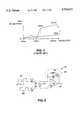
- FIG. 1is a graph illustrating spectral reflectance versus wavelength for soil 1 and a living plant 2. Due to the differences between spectral reflectance characteristics, it is possible to differentiate living plants from bare soil.
- Light beams of two different wavelengths(for example, 670 nm and 750 nm) are transmitted toward, and consequently scattered off of, an object in a field (e.g., a plant or soil).
- the intensities of the different wavelengths of scattered light returning from the objectare compared to determine the whether the object is a plant or soil. For example, if the intensity values of the scattered light are consistent with the spectral reflectance characteristics of a plant, then the object from which the beams are scattered is assumed to be a plant.
- the foregoing methodmay be used advantageously to reduce the amount of herbicide required to eradicate weeds.
- a field containing weedsmay be scanned using light beams of two different wavelengths as described above.
- a solenoid valveis opened so that herbicide is sprayed directly onto the weed.
- a considerable savings in herbicidemay result because herbicide is not sprayed unnecessarily onto bare soil.
- FIG. 2is a diagram of one embodiment of an electronic sprayer.
- a first diode 3emits light of a first wavelength (e.g., 750 nm) and a second diode 4 emits light of a second wavelength (e.g., 670 nm).
- the drive currents of diode 3 and diode 4are each modulated with respective modulation signals MA and MB, which are of the same frequency but of different phase.
- a resonant circuit 10is tuned to the frequency of modulation signals MA and MB.
- the phase of the scattered light impinging upon photodetector 9is used to assess the spectral reflectance characteristic of the scattered light, and therefore to characterize the object (e.g., plant or soil) from which the light is scattered. For example, if the light from diode 4 were completely absorbed by weed 6, then the only light received by photodetector 9 would be from diode 3. Photodetector 9 would therefore be modulated with a modulation signal approximately in phase with the modulation signal MA driving diode 3.
- photodetector 9typically receives some light from each of diodes 3 and 4. Then, depending on the relative reflectance values, the phase of resonant circuit 10 will lie between the first and second extreme phase relationships described above.
- a phase detectordetects the phase of the oscillation induced in resonant circuit 10, providing phase information indicative of the relative strengths of the scattered light beams from diodes 3 and 4. If this phase information is consistent with the spectral reflectance characteristic of a weed, then a solenoid valve 11 is opened to spray herbicide onto weed 6. Conversely, if the phase information is consistent with the spectral reflectance characteristic of soil, then solenoid valve 11 remains closed.
- the ability of the electronic sprayer to distinguish plants from soildepends upon the accuracy of resonant circuit 10. It is therefore important that the frequency and phase of resonant circuit 10 remain stable as the electronic sprayer moves across a field.
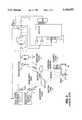
- FIG. 3is a simplified diagram of a photodetector amplifier circuit 12 used to receive scattered light.
- Tuned resonant circuit 10includes an inductor 13 and a capacitor 14 connected in parallel between ground potential and the gate of a field effect transistor 15.
- Transistor 15 and resistors 16 and 17form an amplifier having an output terminal V OUT .
- inductor 13 of tuned circuit 10forms a low-impedance path from the gate of transistor 15 to ground, thereby reducing the gain of the amplifier.
- capacitor 14 of the tuned circuit 10forms a low-impedance path from the gate of transistor 15 to ground, once again reducing the gain of the amplifier.
- the amplifierexhibits maximum gain at an intermediate frequency f o determined by the inductance of inductor 13 (I 13 ) and the capacitance of capacitor 14 (C 14 ) according to the following well-known relationship: ##EQU1## Intermediate frequency f o is selected to correspond with the frequency of the modulation signals MA and MB. Radiation A from diode 3 increases the magnitude of the reverse-bias current through photodetector 18.
- the on-off modulation of radiation A due to the modulation signal MAcauses the voltage on the gate of transistor 15 to oscillate at the frequency of the modulation signal MA (for example, 455 Khz).
- the phase of the oscillationis dependent upon the phase of the modulation signal MA. If photodetector 18 receives radiation from diode 4, then the voltage on the gate of transistor 15 will oscillate at the same frequency; however, the phase of the oscillation will depend instead upon the phase of the modulation signal MB.
- FIG. 4shows that the maximum impedance of resonant circuit 10 occurs at 455 Khz. Consequently, the f o of photodetector circuit 12 is also 455 Khz. It was discovered however that the intermediate frequency f o of photodetector circuit 12 changes when ambient light is incident on photodetector 18. Curves 21 and 22 represent the respective impedance of resonant circuit 10 with and without ambient sunlight impinging upon photodetector 18.
- phase shiftsare undesirable because, as explained above, the phase of scattered light impinging upon photodetector 9 is used to characterize objects from which the light is scattered. Consequently, phase errors due to changes in ambient light degrade the ability of the electronic sprayer to distinguish plants from soil. There is therefore a need for a photodetector circuit that is insensitive to changes in the level of ambient light.
- An agricultural implement for spraying herbicide on weeds in a field without spraying herbicide on the bare soilincludes a photodetector circuit.
- the photodetector circuitincludes a photodetector and an active filter.
- the photodetectoris not AC coupled in parallel with an inductor/capacitor resonant circuit that tunes the active filter.
- changes in photodetector capacitance due to changes in ambient lighting conditionsare not impressed across the resonant inductor/capacitor circuit, and therefore do not adversely change the frequency and phase characteristics of the photodetector circuit.
- FIG. 1(Prior Art) is a graph illustrating spectral reflectances representative of soil and a living plant.
- FIG. 2(Prior Art) is a diagram of one embodiment of an electronic sprayer.
- FIG. 3is a simplified diagram of a photodetector amplifier circuit used to receive radiation scattered from an object in a field.
- FIG. 4(Prior Art) are graphs illustrating the impedance and phase response of the resonant circuit 10 of FIG. 3.
- FIG. 5is a cross-sectional diagram of a photodiode.
- FIG. 6is an AC model of part of the photodetector circuit of FIG. 3.
- FIGS. 7a, 7b, and 7cdepict the action of photogenerated charge carriers in a conventional photodiode.
- FIG. 8is a simplified diagram of an embodiment of a photodetector circuit 100.
- FIGS. 9a, 9b, 10a, and 10bare diagrams of other embodiments of photodetector circuits.
- FIG. 5is a cross-sectional diagram of a photodiode 23, which conventionally includes an intrinsic layer 24 sandwiched between a p-type layer 25 and an n-type layer 26, is used to explain the operation of photodetector 18.
- a depletion regionextends a distance x P into layer 25 and a distance X N into layer 26.
- ⁇ Iis the built-in potential of a p-n junction
- nis a number typically ranging from one-third to one-half
- Kis a constant for a given p-n junction.
- Photodiodesexhibit a capacitance that varies with the depth of the total non-conductive region x T .
- This well-known relationshipmay be expressed as follows: ##EQU2## where A is the junction area and ⁇ s is the permittivity of silicon.
- Equation 4Based on the relationship expressed in equation 4, a theory was devised to explain why changes in ambient light affected the tuned frequency of photodetector circuit 12. The basic theory is as follows:
- FIG. 6is an AC model of a portion of photodetector circuit 12 of FIG. 3.
- the ten-volt power supply (not shown) connected to the +10 volt terminal of FIG. 3is effectively an AC ground.
- the series-connected photodetector 18 and dequeuing resistor 19are shown in FIG. 6 connected in parallel with the resonant inductor 13 and capacitor 14. Resistor 19 is removed so that the voltage across diode 18 remains constant. Unfortunately, even with the voltage across diode 18 held constant, sunlight incident on photodetector 18 still affects the resonant frequency of photodetector circuit 12.
- capacitance C PD of the photodetector 18can change even if the voltage across photodetector 18 remains constant, and that such changes in the capacitance C PD of photodetector 18 affect the resonant frequency of resonant circuit 10 when sunlight is incident on photodetector 18.
- FIG. 7ais another cross-sectional diagram of photodiode 23 of FIG. 5. Arrows conventionally represent an electric field induced by voltage source V BIAS . The minus and plus signs represent the charge of the depletion regions in p-type layer 25 and the n-type layer 26, respectively.
- equation 5requires that the integrated electric field (represented by the arrows) must also remain constant.
- FIG. 7cshows additional positive and negative stored charge in regions 26 and 28, respectively, that compensate for the opposing electric field induced by the charges in intrinsic layer 24.
- the additional charges in the depletion regions of p-type layer 25 and n-type layer 26widen each depletion region so that the total non-conductive region x T increase to x T '.
- the depletion regions in each of layers 25 and 26widen so that the integral of equation 5 is satisfied.
- equation 1provides that decreasing the capacitance of diode 23, if it were to effect the capacitance of resonant circuit 10, would increase the intermediate frequency f o .
- FIG. 8is a simplified diagram of an embodiment of a photodetector circuit 100 in accordance with the present invention.
- a photodetector 101is connected to a resonant inductor/capacitor circuit 102 and to an input terminal of an operational amplifier 103.
- the photodetector circuit 100is configured so that photodetector 101 is not connected in parallel with circuit 102.
- inductor/capacitor circuit 102is connected in a negative feedback loop of an operational amplifier 103.
- the inductance of the inductor 104 and the capacitance of capacitor 105are chosen to correspond with the frequency of the modulation signals MA and MB.
- the output node 107which is coupled to one end of the resonant inductor/capacitor circuit 102, is electrically isolated from the cathode of photodetector 101. Consequently, changes in the capacitance of photodiode 101 do not affect the capacitance of resonant inductor/capacitor circuit 102.
- output node 107is electrically isolated from the anode of diode 101.
- diode 101 of FIG. 8may be reversed so that the cathode is connected to the inverting input terminal of amplifier 103 and the anode is connected to the non-inverting input terminal.
- diode 101should not be connected in parallel with capacitor 105, so that any change in the capacitance of diode 101 will not affect the intermediate frequency of inductor/capacitor circuit 102.
- the amplitudes of any interfering signals from resonant inductor/capacitor circuit 102 developed across the input terminals of operational amplifier 103are preferably at least six decibels (and preferable much more) below the amplitude of the signal developed across resonant inductor/capacitor circuit 102.
- FIGS. 9A and 9Bare a more detailed diagram of a photodetector circuit similar to photodetector circuit 100 of FIG. 8.
- the resonant inductor/capacitor circuit 200 in this embodimentis again connected in a negative feedback loop of an operational amplifier 201.
- a photodetector 202is coupled between the inverting and non-inverting inputs of the operational amplifier 201.
- the signal output from operational amplifier 201is filtered by an active bandpass filter 204.
- the filtered signalis supplied to an FM detector 205.
- FM detector 205is commercially available from Philips Semiconductor of Sunnyvale, Calif., as part number NE614A.
- the output node of operational amplifier 201which is coupled to one end of the resonant inductor/capacitor circuit 200, is electrically isolated from the cathode of photodetector 202.
- FIGS. 10A and 10Bare a diagram of another embodiment of a photodetector circuit.
- the resonant inductor/capacitor circuit 300 in this embodimentis again connected in a negative feedback loop of an operational amplifier 301.
- a photodetector 302is coupled to the inverting input of the operational amplifier 301 via a common base coupled bipolar transistor 303.
- the signal output from the operational amplifier 301is filtered by a ceramic bandpass filter 304, part number CFU455B2, available from Murata Electronics North America, Inc., of State College, Pa.
- the filtered signalis again to an FM detector circuit 305 similar to circuit 205 of FIG. 9B.
- the output node of operational amplifier 301which is coupled to one end of the resonant inductor/capacitor circuit 300, is electrically isolated from the anode of photodetector 302.
Landscapes
- Physics & Mathematics (AREA)
- Spectroscopy & Molecular Physics (AREA)
- General Physics & Mathematics (AREA)
- Life Sciences & Earth Sciences (AREA)
- Sustainable Development (AREA)
- Investigating Or Analysing Materials By Optical Means (AREA)
Abstract
Description
x.sub.P +x.sub.N =K(φ.sub.I -V.sub.BIAS).sup.n (EQ. 2)
V=-∫Eδx (EQ. 5)
Claims (15)
Priority Applications (3)
| Application Number | Priority Date | Filing Date | Title |
|---|---|---|---|
| US08/705,381US5763873A (en) | 1996-08-28 | 1996-08-28 | Photodetector circuit for an electronic sprayer |
| PCT/US1997/014816WO1998011587A2 (en) | 1996-08-28 | 1997-08-26 | Photodetector circuit for an electronic sprayer |
| AU40834/97AAU4083497A (en) | 1996-08-28 | 1997-08-26 | Photodetector circuit for an electronic sprayer |
Applications Claiming Priority (1)
| Application Number | Priority Date | Filing Date | Title |
|---|---|---|---|
| US08/705,381US5763873A (en) | 1996-08-28 | 1996-08-28 | Photodetector circuit for an electronic sprayer |
Publications (1)
| Publication Number | Publication Date |
|---|---|
| US5763873Atrue US5763873A (en) | 1998-06-09 |
Family
ID=24833220
Family Applications (1)
| Application Number | Title | Priority Date | Filing Date |
|---|---|---|---|
| US08/705,381Expired - LifetimeUS5763873A (en) | 1996-08-28 | 1996-08-28 | Photodetector circuit for an electronic sprayer |
Country Status (3)
| Country | Link |
|---|---|
| US (1) | US5763873A (en) |
| AU (1) | AU4083497A (en) |
| WO (1) | WO1998011587A2 (en) |
Cited By (49)
| Publication number | Priority date | Publication date | Assignee | Title |
|---|---|---|---|---|
| US6062496A (en)* | 1996-06-17 | 2000-05-16 | Patchen, Inc. | Valve cartridge having pressure sensor for agriculture and weed control |
| US20020024665A1 (en)* | 1999-06-30 | 2002-02-28 | Masten Billy R. | Digital spectral identifier-controller and related methods |
| US6596996B1 (en) | 2001-07-24 | 2003-07-22 | The Board Of Regents For Oklahoma State University | Optical spectral reflectance sensor and controller |
| US6601341B2 (en) | 2001-07-24 | 2003-08-05 | The Board Of Regents For Oklahoma State University | Process for in-season fertilizer nitrogen application based on predicted yield potential |
| US20040034459A1 (en)* | 2000-10-14 | 2004-02-19 | Ingo Hoelscher | System for the application of pesticides |
| US6702200B2 (en) | 2001-07-24 | 2004-03-09 | The Board Of Regents For Oklahoma State University | Nozzle attitude controller for spot and variable rate application of agricultural chemicals and fertilizers |
| US6756578B1 (en) | 2002-01-17 | 2004-06-29 | Trimble Navigation Limited | Photocell bias circuit |
| US20040231239A1 (en)* | 2001-07-24 | 2004-11-25 | The Board Of Regents For Oklahoma State University | Use of within-field-element-size CV for improved nutrient fertilization in crop production |
| US20040237394A1 (en)* | 2001-07-24 | 2004-12-02 | Mayfield Ted E. | Low-cost system and method for the precision application of agricultural products |
| US20050000277A1 (en)* | 2003-03-10 | 2005-01-06 | Capstan'ag Systems, Inc. | Flow control and operation monitoring system for individual spray nozzles |
| US20050024213A1 (en)* | 2003-08-01 | 2005-02-03 | David Franzen | Sensor and method of detecting the condition of a turf grass |
| US20050098713A1 (en)* | 2003-09-23 | 2005-05-12 | Kyle Holland | Light sensor with modulated radiant polychromatic source |
| US20060050285A1 (en)* | 2004-09-06 | 2006-03-09 | Weller Keith S | Position Encoder with Directional Output |
| US20060054790A1 (en)* | 2004-09-15 | 2006-03-16 | Schmidt Glen E | Photodiode amplifier |
| US20060086824A1 (en)* | 2004-10-21 | 2006-04-27 | Nhc Corporation | Automatic light-activated portable mist sprayer device |
| US20060225489A1 (en)* | 2005-04-12 | 2006-10-12 | Giles Durham K | System and method for determining atomization characteristics of spray liquids |
| US20060273189A1 (en)* | 2005-06-07 | 2006-12-07 | Capstan Ag Systems, Inc. | Electrically actuated variable pressure control system |
| US20080114498A1 (en)* | 2005-05-23 | 2008-05-15 | Capstan Ag Systems, Inc. | Networked Diagnostic and Control System For Dispensing Apparatus |
| US20080191054A1 (en)* | 2007-02-09 | 2008-08-14 | Tsd Integrated Controls, Llc | Method and system for applying materials to crops |
| US20080291455A1 (en)* | 2003-11-07 | 2008-11-27 | Kyle Harold Holland | Active Light Sensor |
| US20090007485A1 (en)* | 2007-07-03 | 2009-01-08 | Holland Scientific | Sensor-Based Chemical Management for Agricultural Landscapes |
| US20100019128A1 (en)* | 2008-07-23 | 2010-01-28 | Princeton Lightwave, Inc. | Focal Plane Array Imager |
| US20100132439A1 (en)* | 2005-04-12 | 2010-06-03 | Durham Kenimer Giles | System and method for determining atomization characteristics of spray liquids |
| US20100222922A1 (en)* | 2007-07-03 | 2010-09-02 | Holland Kyle H | Variable rate chemical management for agricultural landscapes |
| US20110047867A1 (en)* | 2003-11-07 | 2011-03-03 | Holland Kyle H | Plant treatment based on a water invariant chlorophyll index |
| US20110291751A1 (en)* | 2009-01-22 | 2011-12-01 | Samsung Electronics Co., Ltd. | Phase matching band-pass filter using exponential function approximation |
| US20120029692A1 (en)* | 2010-07-29 | 2012-02-02 | Owen Gary M | Automated pill dispensing systems for detecting characteristics of bottles in output chutes using modulated light sources and related methods of operation |
| US8189189B1 (en) | 2008-10-08 | 2012-05-29 | Herendeen Robert O | LED sensor for process control |
| US8430337B2 (en) | 2004-10-21 | 2013-04-30 | Nch Corporation | Light-activated portable aerosol mist sprayer device |
| US20130181613A1 (en)* | 2010-07-30 | 2013-07-18 | Mechaless Systems Gmbh | Opto-electronic measuring arrangement with electro-optical basic coupling |
| US8816262B2 (en) | 2007-07-03 | 2014-08-26 | Kyle H. Holland | Auto-calibration method for real-time agricultural sensors |
| US8942893B2 (en) | 2012-09-07 | 2015-01-27 | Trimble Navigation Limited | Predictive boom shape adjustment |
| US9026316B2 (en) | 2012-10-02 | 2015-05-05 | Kyle H. Holland | Variable rate chemical management for agricultural landscapes with nutrition boost |
| US9282693B2 (en) | 2013-02-20 | 2016-03-15 | Deere & Company | Data encoding with planting attributes |
| USD766399S1 (en) | 2014-10-03 | 2016-09-13 | Deere & Company | Hybrid spray nozzle turret |
| US9585307B2 (en) | 2007-07-03 | 2017-03-07 | Kyle H. Holland | Optical real-time soil sensor and auto-calibration methods |
| US9661809B2 (en) | 2012-09-07 | 2017-05-30 | Trimble Navigation Limited | Dynamic application system priming |
| US9884330B2 (en) | 2014-06-20 | 2018-02-06 | Deere & Company | Broadband spray nozzle systems and methods |
| US10189031B2 (en) | 2014-06-20 | 2019-01-29 | Deere & Company | Hybrid flow nozzle and control system |
| US10255670B1 (en) | 2017-01-08 | 2019-04-09 | Dolly Y. Wu PLLC | Image sensor and module for agricultural crop improvement |
| US10656133B2 (en) | 2018-10-19 | 2020-05-19 | Trimble Inc. | Controlling plant detection systems using phase delay analysis |
| WO2020142822A1 (en)* | 2019-01-10 | 2020-07-16 | Eirene Projetos E Consultoria Ltda | Device provided with a viewing and identification system installed on agricultural equipment |
| US10721859B2 (en) | 2017-01-08 | 2020-07-28 | Dolly Y. Wu PLLC | Monitoring and control implement for crop improvement |
| US10773271B2 (en) | 2014-06-20 | 2020-09-15 | Deere & Company | Time varying control of the operation of spray systems |
| US10775299B2 (en)* | 2019-01-08 | 2020-09-15 | Trimble Inc. | Optical tuning for plant detection |
| US10921189B2 (en) | 2018-08-23 | 2021-02-16 | Trimble Inc. | Detecting the presence of plants on the ground |
| RU2747624C1 (en)* | 2020-11-11 | 2021-05-11 | Общество с ограниченной ответственностью "Аргонавт" | Wireless device for controlling operation of agricultural sprayers |
| US11607703B2 (en)* | 2020-03-10 | 2023-03-21 | Cnh Industrial America Llc | Sensor system and related method for adjusting the operating position of sensors of an agricultural sprayer |
| US12115546B2 (en) | 2014-06-20 | 2024-10-15 | Deere & Company | Hybrid flow nozzle system |
Citations (65)
| Publication number | Priority date | Publication date | Assignee | Title |
|---|---|---|---|---|
| SU203340A1 (en)* | К. К. Полевицкий | AUTOMATIC CREATOR OF CULTURAL PLANTS, EXAMPLE OF SUGAR BEET | ||
| GB590598A (en)* | 1943-04-12 | 1947-07-23 | Leo Aloysius Marihart | Agricultural machines for hoeing, weeding or thinning |
| US2514405A (en)* | 1948-05-14 | 1950-07-11 | M P H Ind | Photoelectric unit for agricultural operations |
| US2682132A (en)* | 1948-05-14 | 1954-06-29 | M P H Ind | Agricultural machine |
| US2894178A (en)* | 1956-01-18 | 1959-07-07 | Hewlett Packard Co | Photoelectric system |
| US3373870A (en)* | 1966-07-08 | 1968-03-19 | American Tobacco Co | Cigar classification apparatus |
| US3488511A (en)* | 1966-10-25 | 1970-01-06 | Tokyo Shibaura Electric Co | Automatic identifying apparatus of postage stamp indications |
| US3512587A (en)* | 1967-10-09 | 1970-05-19 | Eversman Mfg Co | Photoelectrically controlled plant thinners |
| US3590925A (en)* | 1968-05-06 | 1971-07-06 | Tara Corp | Automated agricultural system |
| US3609913A (en)* | 1969-07-24 | 1971-10-05 | Int Electric Fence Co Inc | Magnetic memory control |
| US3652844A (en)* | 1970-02-09 | 1972-03-28 | Ralph A Scott Jr | Laser plant control |
| US3701218A (en)* | 1969-08-07 | 1972-10-31 | Deere & Co | Spray type row crop thinner |
| SU382367A1 (en)* | 1971-11-15 | 1973-05-25 | Полтавский ордена Трудового Красного Знамени сельскохоз йственный институт | |
| US3821550A (en)* | 1969-07-18 | 1974-06-28 | Deere & Co | Plant thinner having radiant energy plant detecting means |
| SU471074A1 (en)* | 1973-06-11 | 1975-05-25 | Полтавский Ордена Трудового Красного Знамени Сельскохозяйственный Институт | The way to recognize plants from soil lumps and stones |
| US3910701A (en)* | 1973-07-30 | 1975-10-07 | George R Henderson | Method and apparatus for measuring light reflectance absorption and or transmission |
| SU547183A1 (en)* | 1975-02-24 | 1977-02-25 | Кировоградский институт сельскохозяйственного машиностроения | The way to recognize plants on the background of the soil |
| US4013875A (en)* | 1974-01-11 | 1977-03-22 | Mcglynn Daniel R | Vehicle operation control system |
| US4015366A (en)* | 1975-04-11 | 1977-04-05 | Advanced Decision Handling, Inc. | Highly automated agricultural production system |
| US4029391A (en)* | 1974-08-22 | 1977-06-14 | Sterndent Corporation | Light probe and interface therefor |
| US4092800A (en)* | 1973-09-24 | 1978-06-06 | Phytox Corporation | Vegetation control |
| US4179216A (en)* | 1977-05-31 | 1979-12-18 | Franz Plasser Bahnbaumaschinen-Industriegesellschaft M.B.H. | Apparatus for measuring the profile of a railroad tunnel |
| US4206569A (en)* | 1978-09-05 | 1980-06-10 | Randolph Joe G | Weed sprayer |
| US4354339A (en)* | 1980-11-14 | 1982-10-19 | Clarence Nokes | Lawn mower apparatus |
| US4369886A (en)* | 1979-10-09 | 1983-01-25 | Ag-Electron, Inc. | Reflectance ratio sorting apparatus |
| US4482960A (en)* | 1981-11-20 | 1984-11-13 | Diffracto Ltd. | Robot tractors |
| US4527897A (en)* | 1981-09-18 | 1985-07-09 | Tokyo Shibaura Denki Kabushiki Kaisha | Apparatus for detecting specific color |
| US4550526A (en)* | 1984-01-23 | 1985-11-05 | Willard Smucker | Implement for contact application of liquid herbicides to crops |
| US4558786A (en)* | 1983-06-15 | 1985-12-17 | Marvin M. Lane | Electro-optical sorter |
| US4618257A (en)* | 1984-01-06 | 1986-10-21 | Standard Change-Makers, Inc. | Color-sensitive currency verifier |
| US4626993A (en)* | 1982-02-19 | 1986-12-02 | Kubota, Ltd. | Teaching-playback type automatically running vehicle |
| US4626678A (en)* | 1983-04-05 | 1986-12-02 | Sumitomo Electric Industries, Ltd. | Light detecting circuit |
| US4628454A (en)* | 1982-07-13 | 1986-12-09 | Kubota, Ltd. | Automatic running work vehicle |
| US4630773A (en)* | 1984-11-06 | 1986-12-23 | Soil Teq., Inc. | Method and apparatus for spreading fertilizer |
| US4674048A (en)* | 1983-10-26 | 1987-06-16 | Automax Kabushiki-Kaisha | Multiple robot control system using grid coordinate system for tracking and completing travel over a mapped region containing obstructions |
| US4699273A (en)* | 1983-12-06 | 1987-10-13 | Gunson's Sortex Limited | Sorting machine |
| US4709265A (en)* | 1985-10-15 | 1987-11-24 | Advanced Resource Development Corporation | Remote control mobile surveillance system |
| US4709505A (en)* | 1984-02-13 | 1987-12-01 | Lempa Jr Bernard J | Herbicide applicator apparatus |
| US4731529A (en)* | 1985-04-03 | 1988-03-15 | Canon Kabushiki Kaisha | Light measuring circuit having circuitry for bypassing a low frequency component in the output of a photoelectric conversion element |
| US4744207A (en)* | 1986-08-25 | 1988-05-17 | J. I. Case Company | Programmable compactor for cotton harvester |
| GB2200446A (en)* | 1987-01-27 | 1988-08-03 | So Resprom | Colour sensor for crop identification |
| US4768715A (en)* | 1987-03-24 | 1988-09-06 | Brian Sali | Vehicle mountable liquid spray system |
| US4768713A (en)* | 1982-12-15 | 1988-09-06 | Roper Bert E | Grove sprayer |
| US4789777A (en)* | 1986-06-24 | 1988-12-06 | Asahi Kogaku Kogyo Kabushiki Kaisha | Photelectric amplifier having plural actuable feedback paths |
| US4878598A (en)* | 1987-04-30 | 1989-11-07 | California Fresno Transportation, Inc. | Method and apparatus for dispensing a substance to a work area |
| US4991341A (en)* | 1988-01-19 | 1991-02-12 | Fmc Corporation | Control system for uniform spraying of plants |
| US5015868A (en)* | 1987-11-30 | 1991-05-14 | Goldstar Co., Ltd. | Real time distance sensor |
| NZ229625A (en)* | 1988-06-22 | 1991-05-28 | Mini For Agriculture And Rural | Sprayer detects presence of vegetation by foliage reflectance |
| US5021645A (en)* | 1989-07-11 | 1991-06-04 | Eaton Corporation | Photoelectric color sensor for article sorting |
| US5050771A (en)* | 1989-07-31 | 1991-09-24 | Field Control Systems, Inc. | Repeatable pattern field spraying control |
| US5068540A (en)* | 1989-08-04 | 1991-11-26 | Ricoh Company, Ltd. | Distance measuring apparatus having automatic gain control |
| US5072128A (en)* | 1989-07-26 | 1991-12-10 | Nikon Corporation | Defect inspecting apparatus using multiple color light to detect defects |
| US5099113A (en)* | 1990-05-11 | 1992-03-24 | Idec Izumi Corporation | Photoelectrical switching circuit with frequency divider circuit |
| US5109161A (en)* | 1989-10-14 | 1992-04-28 | Canon Kabushiki Kaisha | Light emitter and optical system for a distance measuring device |
| US5222324A (en)* | 1991-02-21 | 1993-06-29 | Neall Donald L O | Crop spraying system |
| US5237386A (en)* | 1989-03-22 | 1993-08-17 | Kidde-Graviner Limited | Optical coupling arrangement for particulate detector |
| US5278423A (en)* | 1992-12-30 | 1994-01-11 | Schwartz Electro-Optics, Inc. | Object sensor and method for use in controlling an agricultural sprayer |
| US5296702A (en)* | 1992-07-28 | 1994-03-22 | Patchen California | Structure and method for differentiating one object from another object |
| US5319196A (en)* | 1992-12-07 | 1994-06-07 | Magnavox Electronic Systems Company | Optical rotation sensor |
| US5386285A (en)* | 1992-02-28 | 1995-01-31 | Mitsubishi Denki Kabushiki Kaisha | Obstacle detecting device for a vehicle |
| US5481104A (en)* | 1994-09-30 | 1996-01-02 | At&T Corp. | Photodetector circuit with actively damped tuned input |
| US5507115A (en)* | 1994-02-04 | 1996-04-16 | Canadian Space Agency | Selective applications of weed control chemicals |
| US5585626A (en)* | 1992-07-28 | 1996-12-17 | Patchen, Inc. | Apparatus and method for determining a distance to an object in a field for the controlled release of chemicals on plants, weeds, trees or soil and/or guidance of farm vehicles |
| US5650748A (en)* | 1994-02-24 | 1997-07-22 | Mcdonnell Douglas Corporation | Ultra-stable gain circuit |
| US5670775A (en)* | 1995-06-23 | 1997-09-23 | Ardac, Inc. | Current-boosted positive feedback logarithmic transresistance amplifier for currency validators |
- 1996
- 1996-08-28USUS08/705,381patent/US5763873A/ennot_activeExpired - Lifetime
- 1997
- 1997-08-26AUAU40834/97Apatent/AU4083497A/ennot_activeAbandoned
- 1997-08-26WOPCT/US1997/014816patent/WO1998011587A2/enactiveApplication Filing
Patent Citations (68)
| Publication number | Priority date | Publication date | Assignee | Title |
|---|---|---|---|---|
| SU203340A1 (en)* | К. К. Полевицкий | AUTOMATIC CREATOR OF CULTURAL PLANTS, EXAMPLE OF SUGAR BEET | ||
| GB590598A (en)* | 1943-04-12 | 1947-07-23 | Leo Aloysius Marihart | Agricultural machines for hoeing, weeding or thinning |
| US2514405A (en)* | 1948-05-14 | 1950-07-11 | M P H Ind | Photoelectric unit for agricultural operations |
| US2682132A (en)* | 1948-05-14 | 1954-06-29 | M P H Ind | Agricultural machine |
| US2894178A (en)* | 1956-01-18 | 1959-07-07 | Hewlett Packard Co | Photoelectric system |
| US3373870A (en)* | 1966-07-08 | 1968-03-19 | American Tobacco Co | Cigar classification apparatus |
| US3488511A (en)* | 1966-10-25 | 1970-01-06 | Tokyo Shibaura Electric Co | Automatic identifying apparatus of postage stamp indications |
| US3512587A (en)* | 1967-10-09 | 1970-05-19 | Eversman Mfg Co | Photoelectrically controlled plant thinners |
| US3590925A (en)* | 1968-05-06 | 1971-07-06 | Tara Corp | Automated agricultural system |
| US3821550A (en)* | 1969-07-18 | 1974-06-28 | Deere & Co | Plant thinner having radiant energy plant detecting means |
| US3609913A (en)* | 1969-07-24 | 1971-10-05 | Int Electric Fence Co Inc | Magnetic memory control |
| US3701218A (en)* | 1969-08-07 | 1972-10-31 | Deere & Co | Spray type row crop thinner |
| US3652844A (en)* | 1970-02-09 | 1972-03-28 | Ralph A Scott Jr | Laser plant control |
| SU382367A1 (en)* | 1971-11-15 | 1973-05-25 | Полтавский ордена Трудового Красного Знамени сельскохоз йственный институт | |
| SU471074A1 (en)* | 1973-06-11 | 1975-05-25 | Полтавский Ордена Трудового Красного Знамени Сельскохозяйственный Институт | The way to recognize plants from soil lumps and stones |
| US3910701A (en)* | 1973-07-30 | 1975-10-07 | George R Henderson | Method and apparatus for measuring light reflectance absorption and or transmission |
| US4092800A (en)* | 1973-09-24 | 1978-06-06 | Phytox Corporation | Vegetation control |
| US4013875A (en)* | 1974-01-11 | 1977-03-22 | Mcglynn Daniel R | Vehicle operation control system |
| US4029391A (en)* | 1974-08-22 | 1977-06-14 | Sterndent Corporation | Light probe and interface therefor |
| SU547183A1 (en)* | 1975-02-24 | 1977-02-25 | Кировоградский институт сельскохозяйственного машиностроения | The way to recognize plants on the background of the soil |
| US4015366A (en)* | 1975-04-11 | 1977-04-05 | Advanced Decision Handling, Inc. | Highly automated agricultural production system |
| US4179216A (en)* | 1977-05-31 | 1979-12-18 | Franz Plasser Bahnbaumaschinen-Industriegesellschaft M.B.H. | Apparatus for measuring the profile of a railroad tunnel |
| US4206569A (en)* | 1978-09-05 | 1980-06-10 | Randolph Joe G | Weed sprayer |
| US4369886A (en)* | 1979-10-09 | 1983-01-25 | Ag-Electron, Inc. | Reflectance ratio sorting apparatus |
| US4354339A (en)* | 1980-11-14 | 1982-10-19 | Clarence Nokes | Lawn mower apparatus |
| US4527897A (en)* | 1981-09-18 | 1985-07-09 | Tokyo Shibaura Denki Kabushiki Kaisha | Apparatus for detecting specific color |
| US4482960A (en)* | 1981-11-20 | 1984-11-13 | Diffracto Ltd. | Robot tractors |
| US4626993A (en)* | 1982-02-19 | 1986-12-02 | Kubota, Ltd. | Teaching-playback type automatically running vehicle |
| US4628454A (en)* | 1982-07-13 | 1986-12-09 | Kubota, Ltd. | Automatic running work vehicle |
| US4768713B1 (en)* | 1982-12-15 | 1995-03-21 | Bert E Roper | Grove sprayer |
| US4768713A (en)* | 1982-12-15 | 1988-09-06 | Roper Bert E | Grove sprayer |
| US4626678A (en)* | 1983-04-05 | 1986-12-02 | Sumitomo Electric Industries, Ltd. | Light detecting circuit |
| US4558786A (en)* | 1983-06-15 | 1985-12-17 | Marvin M. Lane | Electro-optical sorter |
| US4674048A (en)* | 1983-10-26 | 1987-06-16 | Automax Kabushiki-Kaisha | Multiple robot control system using grid coordinate system for tracking and completing travel over a mapped region containing obstructions |
| US4699273A (en)* | 1983-12-06 | 1987-10-13 | Gunson's Sortex Limited | Sorting machine |
| US4618257A (en)* | 1984-01-06 | 1986-10-21 | Standard Change-Makers, Inc. | Color-sensitive currency verifier |
| US4550526A (en)* | 1984-01-23 | 1985-11-05 | Willard Smucker | Implement for contact application of liquid herbicides to crops |
| US4709505A (en)* | 1984-02-13 | 1987-12-01 | Lempa Jr Bernard J | Herbicide applicator apparatus |
| US4630773A (en)* | 1984-11-06 | 1986-12-23 | Soil Teq., Inc. | Method and apparatus for spreading fertilizer |
| US4731529A (en)* | 1985-04-03 | 1988-03-15 | Canon Kabushiki Kaisha | Light measuring circuit having circuitry for bypassing a low frequency component in the output of a photoelectric conversion element |
| US4709265A (en)* | 1985-10-15 | 1987-11-24 | Advanced Resource Development Corporation | Remote control mobile surveillance system |
| US4789777A (en)* | 1986-06-24 | 1988-12-06 | Asahi Kogaku Kogyo Kabushiki Kaisha | Photelectric amplifier having plural actuable feedback paths |
| US4744207A (en)* | 1986-08-25 | 1988-05-17 | J. I. Case Company | Programmable compactor for cotton harvester |
| GB2200446A (en)* | 1987-01-27 | 1988-08-03 | So Resprom | Colour sensor for crop identification |
| US4768715A (en)* | 1987-03-24 | 1988-09-06 | Brian Sali | Vehicle mountable liquid spray system |
| US4878598A (en)* | 1987-04-30 | 1989-11-07 | California Fresno Transportation, Inc. | Method and apparatus for dispensing a substance to a work area |
| US5015868A (en)* | 1987-11-30 | 1991-05-14 | Goldstar Co., Ltd. | Real time distance sensor |
| US4991341A (en)* | 1988-01-19 | 1991-02-12 | Fmc Corporation | Control system for uniform spraying of plants |
| NZ229625A (en)* | 1988-06-22 | 1991-05-28 | Mini For Agriculture And Rural | Sprayer detects presence of vegetation by foliage reflectance |
| US5144767A (en)* | 1988-06-22 | 1992-09-08 | The Minister For Agriculture & Rural Affairs For The State Of New South Wales | Controller for agricultural sprays |
| US5237386A (en)* | 1989-03-22 | 1993-08-17 | Kidde-Graviner Limited | Optical coupling arrangement for particulate detector |
| US5021645A (en)* | 1989-07-11 | 1991-06-04 | Eaton Corporation | Photoelectric color sensor for article sorting |
| US5072128A (en)* | 1989-07-26 | 1991-12-10 | Nikon Corporation | Defect inspecting apparatus using multiple color light to detect defects |
| US5050771A (en)* | 1989-07-31 | 1991-09-24 | Field Control Systems, Inc. | Repeatable pattern field spraying control |
| US5068540A (en)* | 1989-08-04 | 1991-11-26 | Ricoh Company, Ltd. | Distance measuring apparatus having automatic gain control |
| US5109161A (en)* | 1989-10-14 | 1992-04-28 | Canon Kabushiki Kaisha | Light emitter and optical system for a distance measuring device |
| US5099113A (en)* | 1990-05-11 | 1992-03-24 | Idec Izumi Corporation | Photoelectrical switching circuit with frequency divider circuit |
| US5222324A (en)* | 1991-02-21 | 1993-06-29 | Neall Donald L O | Crop spraying system |
| US5386285A (en)* | 1992-02-28 | 1995-01-31 | Mitsubishi Denki Kabushiki Kaisha | Obstacle detecting device for a vehicle |
| US5389781A (en)* | 1992-07-28 | 1995-02-14 | Patchen California | Structure and method usable for differentiating a plant from soil in a field |
| US5296702A (en)* | 1992-07-28 | 1994-03-22 | Patchen California | Structure and method for differentiating one object from another object |
| US5585626A (en)* | 1992-07-28 | 1996-12-17 | Patchen, Inc. | Apparatus and method for determining a distance to an object in a field for the controlled release of chemicals on plants, weeds, trees or soil and/or guidance of farm vehicles |
| US5319196A (en)* | 1992-12-07 | 1994-06-07 | Magnavox Electronic Systems Company | Optical rotation sensor |
| US5278423A (en)* | 1992-12-30 | 1994-01-11 | Schwartz Electro-Optics, Inc. | Object sensor and method for use in controlling an agricultural sprayer |
| US5507115A (en)* | 1994-02-04 | 1996-04-16 | Canadian Space Agency | Selective applications of weed control chemicals |
| US5650748A (en)* | 1994-02-24 | 1997-07-22 | Mcdonnell Douglas Corporation | Ultra-stable gain circuit |
| US5481104A (en)* | 1994-09-30 | 1996-01-02 | At&T Corp. | Photodetector circuit with actively damped tuned input |
| US5670775A (en)* | 1995-06-23 | 1997-09-23 | Ardac, Inc. | Current-boosted positive feedback logarithmic transresistance amplifier for currency validators |
Non-Patent Citations (21)
| Title |
|---|
| "A New Age of Weed Control", Kelly Baron, The Grower, pp. 20-24 (Feb. 1993). |
| "Sucker Punch", California Farmer, p. 18 (Feb. 1995). |
| "The Newest Weedseeker is a Hit", Patchen On Target, 4 pages, (Spring 1995). (no month). |
| "Waging War on Weeds", Grape Grower, Marni Katz, vol. 27, No. 9, 4 pages (Sep. 1995). |
| A New Age of Weed Control , Kelly Baron, The Grower, pp. 20 24 (Feb. 1993).* |
| B. B. Nitsch et al., "Visible And Near Infrared Plant, Soil And Crop Residue Reflectivity For Weed Sensor Design", American Society of Agricultural Engineers, Jun. 23-26, 1991). |
| B. B. Nitsch et al., Visible And Near Infrared Plant, Soil And Crop Residue Reflectivity For Weed Sensor Design , American Society of Agricultural Engineers, Jun. 23 26, 1991).* |
| Geoffrey J. Shropshire et al., "Fourier and Hadamard Transforms For Detecting Weeds in Video Images", pp. 1-18, American Society of Agricultural Engineers, (Dec. 12-15, 1989). |
| Geoffrey J. Shropshire et al., "Optical Reflectance Sensor for Detecting Plants", SPIE vol. 1379, pp. 222-235, (1990). no month. |
| Geoffrey J. Shropshire et al., Fourier and Hadamard Transforms For Detecting Weeds in Video Images , pp. 1 18, American Society of Agricultural Engineers, (Dec. 12 15, 1989).* |
| Geoffrey J. Shropshire et al., Optical Reflectance Sensor for Detecting Plants , SPIE vol. 1379, pp. 222 235, (1990). no month.* |
| Patchen On Target, 4 pages (Fall 1994). (no month).* |
| Patchen On Target, 4 pages (Spring 1994). (no month).* |
| Patchen On Target, 4 pages, (Winter 1993). (no month).* |
| Patchen Selective Spray Systems, "Reduced Herbicide Usage is Perennial Crops, Row Crops, Fallow Land and Non-Agricultural Applications Using Optoelectronic Detection", 10 pages, (1994). |
| Patchen Selective Spray Systems, Reduced Herbicide Usage is Perennial Crops, Row Crops, Fallow Land and Non Agricultural Applications Using Optoelectronic Detection , 10 pages, (1994).* |
| Proceedings of the 1991 Symposium, American Society of Agricultural Engineers, W. L. Felton et al., "A Microprocessor Controlled Technology To Selectively Spot Spray Weeds", 8 pages (Dec. 16-17 1991). |
| Proceedings of the 1991 Symposium, American Society of Agricultural Engineers, W. L. Felton et al., A Microprocessor Controlled Technology To Selectively Spot Spray Weeds , 8 pages (Dec. 16 17 1991).* |
| Sucker Punch , California Farmer, p. 18 (Feb. 1995).* |
| The Newest Weedseeker is a Hit , Patchen On Target, 4 pages, (Spring 1995). (no month).* |
| Waging War on Weeds , Grape Grower, Marni Katz, vol. 27, No. 9, 4 pages (Sep. 1995).* |
Cited By (92)
| Publication number | Priority date | Publication date | Assignee | Title |
|---|---|---|---|---|
| US6062496A (en)* | 1996-06-17 | 2000-05-16 | Patchen, Inc. | Valve cartridge having pressure sensor for agriculture and weed control |
| US20020024665A1 (en)* | 1999-06-30 | 2002-02-28 | Masten Billy R. | Digital spectral identifier-controller and related methods |
| US6919959B2 (en) | 1999-06-30 | 2005-07-19 | Masten Opto-Diagnostics Co. | Digital spectral identifier-controller and related methods |
| US6907319B2 (en) | 2000-10-14 | 2005-06-14 | Syngenta Crop Protection, Inc. | System for the application of pesticides |
| US20040034459A1 (en)* | 2000-10-14 | 2004-02-19 | Ingo Hoelscher | System for the application of pesticides |
| US20040231239A1 (en)* | 2001-07-24 | 2004-11-25 | The Board Of Regents For Oklahoma State University | Use of within-field-element-size CV for improved nutrient fertilization in crop production |
| US20040065834A1 (en)* | 2001-07-24 | 2004-04-08 | The Board Of Regents For Oklahoma State University | Optical spectral reflectance sensor and controller |
| US20040237394A1 (en)* | 2001-07-24 | 2004-12-02 | Mayfield Ted E. | Low-cost system and method for the precision application of agricultural products |
| US7188450B2 (en) | 2001-07-24 | 2007-03-13 | The Board Of Regents For Oklahoma State University | Use of within-field-element-size CV for improved nutrient fertilization in crop production |
| US6855933B2 (en) | 2001-07-24 | 2005-02-15 | The Board Of Regents For Oklahoma State University | Optical spectral reflectance sensor and controller |
| US6880291B2 (en) | 2001-07-24 | 2005-04-19 | The Board Of Regents For Oklahoma State University | Process for in-season fertilizer nutrient application based on predicted yield potential |
| US6596996B1 (en) | 2001-07-24 | 2003-07-22 | The Board Of Regents For Oklahoma State University | Optical spectral reflectance sensor and controller |
| US6702200B2 (en) | 2001-07-24 | 2004-03-09 | The Board Of Regents For Oklahoma State University | Nozzle attitude controller for spot and variable rate application of agricultural chemicals and fertilizers |
| US6601341B2 (en) | 2001-07-24 | 2003-08-05 | The Board Of Regents For Oklahoma State University | Process for in-season fertilizer nitrogen application based on predicted yield potential |
| US6756578B1 (en) | 2002-01-17 | 2004-06-29 | Trimble Navigation Limited | Photocell bias circuit |
| US7311004B2 (en) | 2003-03-10 | 2007-12-25 | Capstan Ag Systems, Inc. | Flow control and operation monitoring system for individual spray nozzles |
| US20050000277A1 (en)* | 2003-03-10 | 2005-01-06 | Capstan'ag Systems, Inc. | Flow control and operation monitoring system for individual spray nozzles |
| US7929141B2 (en) | 2003-08-01 | 2011-04-19 | Li-Cor, Inc. | Sensor and method of detecting the condition of a turf grass |
| US8482736B2 (en) | 2003-08-01 | 2013-07-09 | David Franzen | Sensor and method of detecting the condition of a turf grass |
| US7911616B2 (en) | 2003-08-01 | 2011-03-22 | Li-Cor, Inc. | Sensor and method of detecting the condition of a turf grass |
| US20080316491A1 (en)* | 2003-08-01 | 2008-12-25 | Li-Cor, Inc. | Sensor and method of detecting the condition of a turf grass |
| US20060151680A1 (en)* | 2003-08-01 | 2006-07-13 | David Franzen | Sensor and method of detecting the condition of a turf grass |
| US7362439B2 (en) | 2003-08-01 | 2008-04-22 | Li-Cor, Inc. | Method of detecting the condition of a turf grass |
| US20110235043A1 (en)* | 2003-08-01 | 2011-09-29 | Li-Cor, Inc. | Sensor and method of detecting the condition of a turf grass |
| US20050024213A1 (en)* | 2003-08-01 | 2005-02-03 | David Franzen | Sensor and method of detecting the condition of a turf grass |
| US20050098713A1 (en)* | 2003-09-23 | 2005-05-12 | Kyle Holland | Light sensor with modulated radiant polychromatic source |
| US7408145B2 (en) | 2003-09-23 | 2008-08-05 | Kyle Holland | Light sensing instrument with modulated polychromatic source |
| US9075008B2 (en) | 2003-11-07 | 2015-07-07 | Kyle H. Holland | Plant treatment based on a water invariant chlorophyll index |
| US20060208171A1 (en)* | 2003-11-07 | 2006-09-21 | Kyle Holland | Light sensor with modulated radiant polychromatic source |
| US20110047867A1 (en)* | 2003-11-07 | 2011-03-03 | Holland Kyle H | Plant treatment based on a water invariant chlorophyll index |
| US20080291455A1 (en)* | 2003-11-07 | 2008-11-27 | Kyle Harold Holland | Active Light Sensor |
| US20060050285A1 (en)* | 2004-09-06 | 2006-03-09 | Weller Keith S | Position Encoder with Directional Output |
| US7554072B2 (en)* | 2004-09-15 | 2009-06-30 | Siemens Energy & Automation, Inc. | Amplifier configuration with noise reduction for a photodiode |
| US20060054790A1 (en)* | 2004-09-15 | 2006-03-16 | Schmidt Glen E | Photodiode amplifier |
| US20060086824A1 (en)* | 2004-10-21 | 2006-04-27 | Nhc Corporation | Automatic light-activated portable mist sprayer device |
| US20060086823A1 (en)* | 2004-10-21 | 2006-04-27 | Colarusso Joseph T | Light-activated mist sprayer system |
| US7306167B2 (en) | 2004-10-21 | 2007-12-11 | Nch Corporation | Light-activated mist sprayer system |
| US8430337B2 (en) | 2004-10-21 | 2013-04-30 | Nch Corporation | Light-activated portable aerosol mist sprayer device |
| US20060225489A1 (en)* | 2005-04-12 | 2006-10-12 | Giles Durham K | System and method for determining atomization characteristics of spray liquids |
| US8250907B2 (en) | 2005-04-12 | 2012-08-28 | Durham Kenimer Giles | System and method for determining atomization characteristics of spray liquids |
| US20080307893A1 (en)* | 2005-04-12 | 2008-12-18 | Durham Kenimer Giles | System and Method for Determining Atomization Characteristics of Spray Liquids |
| US7278294B2 (en) | 2005-04-12 | 2007-10-09 | Durham Kenimer Giles | System and method for determining atomization characteristics of spray liquids |
| US7665348B2 (en) | 2005-04-12 | 2010-02-23 | Arena Pesticide Management, Inc. | System and method for determining atomization characteristics of spray liquids |
| US20100132439A1 (en)* | 2005-04-12 | 2010-06-03 | Durham Kenimer Giles | System and method for determining atomization characteristics of spray liquids |
| US7502665B2 (en) | 2005-05-23 | 2009-03-10 | Capstan Ag Systems, Inc. | Networked diagnostic and control system for dispensing apparatus |
| US7742842B2 (en) | 2005-05-23 | 2010-06-22 | Capstan Ag Systems, Inc. | Networked diagnostic and control system for dispensing apparatus |
| US7826930B2 (en) | 2005-05-23 | 2010-11-02 | Capstan Ag Systems, Inc. | Networked diagnostic and control system for dispensing apparatus |
| US20080114498A1 (en)* | 2005-05-23 | 2008-05-15 | Capstan Ag Systems, Inc. | Networked Diagnostic and Control System For Dispensing Apparatus |
| US20080114497A1 (en)* | 2005-05-23 | 2008-05-15 | Capstan Ag Systems, Inc. | Networked Diagnostic and Control System for Dispensing Apparatus |
| US20060273189A1 (en)* | 2005-06-07 | 2006-12-07 | Capstan Ag Systems, Inc. | Electrically actuated variable pressure control system |
| US9795977B2 (en) | 2005-06-07 | 2017-10-24 | Capstan Ag Systems, Inc. | Electrically actuated variable pressure control system |
| US7848865B2 (en) | 2007-02-09 | 2010-12-07 | Tsd Integrated Controls, Llc | Method and system for applying materials to crops |
| US20080191054A1 (en)* | 2007-02-09 | 2008-08-14 | Tsd Integrated Controls, Llc | Method and system for applying materials to crops |
| US20100222922A1 (en)* | 2007-07-03 | 2010-09-02 | Holland Kyle H | Variable rate chemical management for agricultural landscapes |
| US20100249998A1 (en)* | 2007-07-03 | 2010-09-30 | Holland Kyle H | Sensor-based chemical management for agricultural landscapes |
| US8816262B2 (en) | 2007-07-03 | 2014-08-26 | Kyle H. Holland | Auto-calibration method for real-time agricultural sensors |
| US20090007485A1 (en)* | 2007-07-03 | 2009-01-08 | Holland Scientific | Sensor-Based Chemical Management for Agricultural Landscapes |
| US8558157B2 (en) | 2007-07-03 | 2013-10-15 | Kyle H. Holland | Sensor-based chemical management for agricultural landscapes |
| US9585307B2 (en) | 2007-07-03 | 2017-03-07 | Kyle H. Holland | Optical real-time soil sensor and auto-calibration methods |
| US7723660B2 (en) | 2007-07-03 | 2010-05-25 | Kyle Holland | Sensor-based chemical management for agricultural landscapes |
| US8319165B2 (en) | 2007-07-03 | 2012-11-27 | Holland Kyle H | Variable rate chemical management for agricultural landscapes |
| US8193482B2 (en) | 2008-07-23 | 2012-06-05 | Princeton Lightwave, Inc. | Negative-feedback avalanche photodetector-based focal-plane-array sensor |
| US20110204210A1 (en)* | 2008-07-23 | 2011-08-25 | Princeton Lightwave, Inc. | Single-Photon Avalanche Detector-Based Focal Plane Array |
| US20100019128A1 (en)* | 2008-07-23 | 2010-01-28 | Princeton Lightwave, Inc. | Focal Plane Array Imager |
| US8026471B2 (en)* | 2008-07-23 | 2011-09-27 | Princeton Lightwave, Inc. | Single-photon avalanche detector-based focal plane array |
| US8189189B1 (en) | 2008-10-08 | 2012-05-29 | Herendeen Robert O | LED sensor for process control |
| US8508292B2 (en)* | 2009-01-22 | 2013-08-13 | Samsung Electronics Co., Ltd. | Phase matching band-pass filter using exponential function approximation |
| US20110291751A1 (en)* | 2009-01-22 | 2011-12-01 | Samsung Electronics Co., Ltd. | Phase matching band-pass filter using exponential function approximation |
| KR101622656B1 (en) | 2009-01-22 | 2016-05-20 | 삼성전자주식회사 | A phase matching band-pass filter using exponential function approximation |
| US8436291B2 (en)* | 2010-07-29 | 2013-05-07 | Parata Systems, Llc | Automated pill dispensing systems for detecting characteristics of bottles in output chutes using modulated light sources and related methods of operation |
| US20120029692A1 (en)* | 2010-07-29 | 2012-02-02 | Owen Gary M | Automated pill dispensing systems for detecting characteristics of bottles in output chutes using modulated light sources and related methods of operation |
| US20130181613A1 (en)* | 2010-07-30 | 2013-07-18 | Mechaless Systems Gmbh | Opto-electronic measuring arrangement with electro-optical basic coupling |
| US8766154B2 (en)* | 2010-07-30 | 2014-07-01 | Mechaless Systems Gmbh | Opto-electronic measuring arrangement with electro-optical basic coupling |
| US8942893B2 (en) | 2012-09-07 | 2015-01-27 | Trimble Navigation Limited | Predictive boom shape adjustment |
| US9661809B2 (en) | 2012-09-07 | 2017-05-30 | Trimble Navigation Limited | Dynamic application system priming |
| US9026316B2 (en) | 2012-10-02 | 2015-05-05 | Kyle H. Holland | Variable rate chemical management for agricultural landscapes with nutrition boost |
| US9282693B2 (en) | 2013-02-20 | 2016-03-15 | Deere & Company | Data encoding with planting attributes |
| US10730065B2 (en) | 2014-06-20 | 2020-08-04 | Deere & Company | Hybrid flow nozzle system |
| US9884330B2 (en) | 2014-06-20 | 2018-02-06 | Deere & Company | Broadband spray nozzle systems and methods |
| US10189031B2 (en) | 2014-06-20 | 2019-01-29 | Deere & Company | Hybrid flow nozzle and control system |
| US12115546B2 (en) | 2014-06-20 | 2024-10-15 | Deere & Company | Hybrid flow nozzle system |
| US10994297B2 (en) | 2014-06-20 | 2021-05-04 | Deere & Company | Hybrid spray apparatus |
| US10773271B2 (en) | 2014-06-20 | 2020-09-15 | Deere & Company | Time varying control of the operation of spray systems |
| USD766399S1 (en) | 2014-10-03 | 2016-09-13 | Deere & Company | Hybrid spray nozzle turret |
| US10721859B2 (en) | 2017-01-08 | 2020-07-28 | Dolly Y. Wu PLLC | Monitoring and control implement for crop improvement |
| US10255670B1 (en) | 2017-01-08 | 2019-04-09 | Dolly Y. Wu PLLC | Image sensor and module for agricultural crop improvement |
| US10921189B2 (en) | 2018-08-23 | 2021-02-16 | Trimble Inc. | Detecting the presence of plants on the ground |
| US10656133B2 (en) | 2018-10-19 | 2020-05-19 | Trimble Inc. | Controlling plant detection systems using phase delay analysis |
| US10775299B2 (en)* | 2019-01-08 | 2020-09-15 | Trimble Inc. | Optical tuning for plant detection |
| WO2020142822A1 (en)* | 2019-01-10 | 2020-07-16 | Eirene Projetos E Consultoria Ltda | Device provided with a viewing and identification system installed on agricultural equipment |
| US11607703B2 (en)* | 2020-03-10 | 2023-03-21 | Cnh Industrial America Llc | Sensor system and related method for adjusting the operating position of sensors of an agricultural sprayer |
| RU2747624C1 (en)* | 2020-11-11 | 2021-05-11 | Общество с ограниченной ответственностью "Аргонавт" | Wireless device for controlling operation of agricultural sprayers |
Also Published As
| Publication number | Publication date |
|---|---|
| WO1998011587A2 (en) | 1998-03-19 |
| AU4083497A (en) | 1998-04-02 |
Similar Documents
| Publication | Publication Date | Title |
|---|---|---|
| US5763873A (en) | Photodetector circuit for an electronic sprayer | |
| US7268858B2 (en) | TOF rangefinding with large dynamic range and enhanced background radiation suppression | |
| US5767538A (en) | Integrated photodiode/transimpedance amplifier | |
| US5481104A (en) | Photodetector circuit with actively damped tuned input | |
| US3927383A (en) | Low noise wide band transducer system | |
| Alexander | Design of wide-band optical heterodyne balanced mixer receivers | |
| Bhaskar et al. | New current-conveyor-based single-resistance-controlled/voltage-controlled oscillator employing grounded capacitors | |
| US7330668B2 (en) | Low noise light receiver | |
| US6993315B1 (en) | Super-regenerative microwave detector | |
| Fonck et al. | Low‐noise photodiode detector for optical fluctuation diagnostics | |
| CA2311433C (en) | Parallel opto-electric structure for high sensitivity and wide bandwidth optical transceiver | |
| EP0794622B1 (en) | Radio receivers with reduced radiation | |
| Xie et al. | Wide‐band frequency response measurements of photodetectors using low‐level photocurrent noise detection | |
| KR20010021686A (en) | Data reception circuit for infrared signals | |
| US6373559B1 (en) | Optoelectronic mixer | |
| EP1042875B1 (en) | An optical transmitter | |
| JP3534443B2 (en) | Optical frequency mixing device | |
| JPS5920299B2 (en) | Photoelectric conversion circuit | |
| Seidl et al. | Single-stage 378MHz 178k/spl Omega/transimpedance amplifier with capacitive-coupled voltage dividers [optical fiber receiver applications] | |
| Matukas et al. | Photosensitivity and Noise Characteristic Investigation of Ultrafast InGaAs/InP Avalanche photodetectors | |
| Ayling et al. | Intrinsically matched 50-ohm laser arrays with greater than 100% quantum efficiencies for optically coupled transistors and low-loss fiber optic links | |
| FR2669167A1 (en) | Infrared signal receiver circuit and remote control assembly employing such a circuit | |
| Datta et al. | S/N Ratio of A Photodiode—Operational Amplifier Combination | |
| JPH04142110A (en) | Photo ic | |
| Akchurin et al. | Frequency domain measurements for laser diagnostics of microwave transistors |
Legal Events
| Date | Code | Title | Description |
|---|---|---|---|
| AS | Assignment | Owner name:PATCHEN, INC., CALIFORNIA Free format text:ASSIGNMENT OF ASSIGNORS INTEREST;ASSIGNORS:BECK, JAMES L.;KINTER, MALCOLM L.;REEL/FRAME:008202/0026 Effective date:19960828 | |
| STCF | Information on status: patent grant | Free format text:PATENTED CASE | |
| FEPP | Fee payment procedure | Free format text:PAT HOLDER CLAIMS SMALL ENTITY STATUS - SMALL BUSINESS (ORIGINAL EVENT CODE: SM02); ENTITY STATUS OF PATENT OWNER: LARGE ENTITY | |
| FPAY | Fee payment | Year of fee payment:4 | |
| AS | Assignment | Owner name:NTECH INDUSTRIES, INC., CALIFORNIA Free format text:ASSIGNMENT OF ASSIGNORS INTEREST;ASSIGNOR:PATCHEN, INC.;REEL/FRAME:013578/0050 Effective date:20021205 | |
| FPAY | Fee payment | Year of fee payment:8 | |
| FEPP | Fee payment procedure | Free format text:PAT HOLDER NO LONGER CLAIMS SMALL ENTITY STATUS, ENTITY STATUS SET TO UNDISCOUNTED (ORIGINAL EVENT CODE: STOL); ENTITY STATUS OF PATENT OWNER: LARGE ENTITY | |
| REFU | Refund | Free format text:REFUND - PAYMENT OF MAINTENANCE FEE, 12TH YR, SMALL ENTITY (ORIGINAL EVENT CODE: R2553); ENTITY STATUS OF PATENT OWNER: LARGE ENTITY | |
| AS | Assignment | Owner name:TRIMBLE NAVIGATION LIMITED, CALIFORNIA Free format text:ASSIGNMENT OF ASSIGNORS INTEREST;ASSIGNOR:NTECH INDUSTRIES, INC.;REEL/FRAME:023355/0698 Effective date:20090918 | |
| FPAY | Fee payment | Year of fee payment:12 |