US5762690A - Dehumidifier for supplying air using variable flow rate and variable pressure in a membrane dryer - Google Patents
Dehumidifier for supplying air using variable flow rate and variable pressure in a membrane dryerDownload PDFInfo
- Publication number
- US5762690A US5762690AUS07/981,191US98119192AUS5762690AUS 5762690 AUS5762690 AUS 5762690AUS 98119192 AUS98119192 AUS 98119192AUS 5762690 AUS5762690 AUS 5762690A
- Authority
- US
- United States
- Prior art keywords
- air
- membrane cartridge
- pressurized air
- source
- flow rate
- Prior art date
- Legal status (The legal status is an assumption and is not a legal conclusion. Google has not performed a legal analysis and makes no representation as to the accuracy of the status listed.)
- Expired - Lifetime
Links
- 239000012528membraneSubstances0.000titleclaimsabstractdescription80
- XLYOFNOQVPJJNP-UHFFFAOYSA-NwaterChemical compoundOXLYOFNOQVPJJNP-UHFFFAOYSA-N0.000claimsabstractdescription26
- 239000012530fluidSubstances0.000claimsabstractdescription19
- 238000001914filtrationMethods0.000claimsdescription20
- 230000007423decreaseEffects0.000abstractdescription22
- 239000003570airSubstances0.000description109
- 239000007789gasSubstances0.000description22
- 239000000835fiberSubstances0.000description10
- 238000009833condensationMethods0.000description7
- 230000005494condensationEffects0.000description7
- IJGRMHOSHXDMSA-UHFFFAOYSA-NAtomic nitrogenChemical compoundN#NIJGRMHOSHXDMSA-UHFFFAOYSA-N0.000description6
- CURLTUGMZLYLDI-UHFFFAOYSA-NCarbon dioxideChemical compoundO=C=OCURLTUGMZLYLDI-UHFFFAOYSA-N0.000description6
- VNWKTOKETHGBQD-UHFFFAOYSA-NmethaneChemical compoundCVNWKTOKETHGBQD-UHFFFAOYSA-N0.000description6
- 230000003247decreasing effectEffects0.000description5
- 230000000694effectsEffects0.000description5
- 239000012466permeateSubstances0.000description5
- QGZKDVFQNNGYKY-UHFFFAOYSA-NAmmoniaChemical compoundNQGZKDVFQNNGYKY-UHFFFAOYSA-N0.000description4
- XKRFYHLGVUSROY-UHFFFAOYSA-NArgonChemical compound[Ar]XKRFYHLGVUSROY-UHFFFAOYSA-N0.000description4
- ATUOYWHBWRKTHZ-UHFFFAOYSA-NPropaneChemical compoundCCCATUOYWHBWRKTHZ-UHFFFAOYSA-N0.000description4
- 239000012510hollow fiberSubstances0.000description4
- UGFAIRIUMAVXCW-UHFFFAOYSA-NCarbon monoxideChemical compound[O+]#[C-]UGFAIRIUMAVXCW-UHFFFAOYSA-N0.000description3
- 230000002411adverseEffects0.000description3
- 230000005540biological transmissionEffects0.000description3
- 239000001569carbon dioxideSubstances0.000description3
- 229910002092carbon dioxideInorganic materials0.000description3
- 229910002091carbon monoxideInorganic materials0.000description3
- 238000007791dehumidificationMethods0.000description3
- 239000001307heliumSubstances0.000description3
- 229910052734heliumInorganic materials0.000description3
- SWQJXJOGLNCZEY-UHFFFAOYSA-Nhelium atomChemical compound[He]SWQJXJOGLNCZEY-UHFFFAOYSA-N0.000description3
- 239000001257hydrogenSubstances0.000description3
- 229910052739hydrogenInorganic materials0.000description3
- 125000004435hydrogen atomChemical class[H]*0.000description3
- 239000007788liquidSubstances0.000description3
- 229910052757nitrogenInorganic materials0.000description3
- 230000001105regulatory effectEffects0.000description3
- RWSOTUBLDIXVET-UHFFFAOYSA-NDihydrogen sulfideChemical compoundSRWSOTUBLDIXVET-UHFFFAOYSA-N0.000description2
- OTMSDBZUPAUEDD-UHFFFAOYSA-NEthaneChemical compoundCCOTMSDBZUPAUEDD-UHFFFAOYSA-N0.000description2
- 239000012080ambient airSubstances0.000description2
- 229910021529ammoniaInorganic materials0.000description2
- 229910052786argonInorganic materials0.000description2
- QVGXLLKOCUKJST-UHFFFAOYSA-Natomic oxygenChemical compound[O]QVGXLLKOCUKJST-UHFFFAOYSA-N0.000description2
- 125000004432carbon atomChemical groupC*0.000description2
- 229930195733hydrocarbonNatural products0.000description2
- 150000002430hydrocarbonsChemical class0.000description2
- 229910000037hydrogen sulfideInorganic materials0.000description2
- 230000006698inductionEffects0.000description2
- 239000000203mixtureSubstances0.000description2
- 238000012986modificationMethods0.000description2
- 230000004048modificationEffects0.000description2
- 239000001301oxygenSubstances0.000description2
- 229910052760oxygenInorganic materials0.000description2
- 239000001294propaneSubstances0.000description2
- 230000008054signal transmissionEffects0.000description2
- 241000883505Leuchtenbergia principisSpecies0.000description1
- 238000009825accumulationMethods0.000description1
- 230000033228biological regulationEffects0.000description1
- 230000001276controlling effectEffects0.000description1
- 230000007547defectEffects0.000description1
- 230000007613environmental effectEffects0.000description1
- 238000009413insulationMethods0.000description1
- 229910052751metalInorganic materials0.000description1
- 239000002184metalSubstances0.000description1
- 238000000034methodMethods0.000description1
- 239000013307optical fiberSubstances0.000description1
- 229920006395saturated elastomerPolymers0.000description1
- 238000009738saturatingMethods0.000description1
- 238000011282treatmentMethods0.000description1
Images
Classifications
- B—PERFORMING OPERATIONS; TRANSPORTING
- B01—PHYSICAL OR CHEMICAL PROCESSES OR APPARATUS IN GENERAL
- B01D—SEPARATION
- B01D53/00—Separation of gases or vapours; Recovering vapours of volatile solvents from gases; Chemical or biological purification of waste gases, e.g. engine exhaust gases, smoke, fumes, flue gases, aerosols
- B01D53/26—Drying gases or vapours
- B01D53/268—Drying gases or vapours by diffusion
- B—PERFORMING OPERATIONS; TRANSPORTING
- B01—PHYSICAL OR CHEMICAL PROCESSES OR APPARATUS IN GENERAL
- B01D—SEPARATION
- B01D53/00—Separation of gases or vapours; Recovering vapours of volatile solvents from gases; Chemical or biological purification of waste gases, e.g. engine exhaust gases, smoke, fumes, flue gases, aerosols
- B01D53/22—Separation of gases or vapours; Recovering vapours of volatile solvents from gases; Chemical or biological purification of waste gases, e.g. engine exhaust gases, smoke, fumes, flue gases, aerosols by diffusion
- F—MECHANICAL ENGINEERING; LIGHTING; HEATING; WEAPONS; BLASTING
- F26—DRYING
- F26B—DRYING SOLID MATERIALS OR OBJECTS BY REMOVING LIQUID THEREFROM
- F26B21/00—Arrangements or duct systems, e.g. in combination with pallet boxes, for supplying and controlling air or gases for drying solid materials or objects
- F26B21/06—Controlling, e.g. regulating, parameters of gas supply
- F26B21/08—Humidity
Definitions
- the present inventionrelates generally to dehumidifying systems that use a membrane cartridge for dehumidifying gases. More particularly, the present invention relates to a dehumidifying system that maintains a certain dew point for a gas without regard to the ambient pressure.
- Dehumidifying systemsare used in a variety of different applications. For example, air dehumidifying systems are used in applications ranging from dehumidification of offices for maintaining comfortable working areas during summer months to providing dry air for dental tools. Different applications often require different levels of humidity. A humidity level of about 40% to 60% is comfortable in homes or offices, while a humidity level of less than 10% is desirable in certain laboratory situations. Even lower humidity levels are often desirable in communications systems.
- Commonly used signal transmission media in communications systemsare waveguide, coaxial cable, multi-wire telephone cables, and optical fiber cables.
- Changing environmental conditionscan affect the overall performance of a system using any of these media. For example, when the temperature of air inside a waveguide or other transmission medium falls below its dew point, condensation occurs inside the transmission line. Condensation lowers the efficiency of waveguide and coaxial cable systems partially because the dielectric constant of water is greater than the dielectric constant of air, and partially because the condensation alters the impedance of the waveguide or coaxial cable and may produce signal variation or loss. In multi-wire cables, condensation can lower the insulation resistance and introduce undesirable leakage paths.
- the transmission lineis normally sealed and pressurized to prevent the ingress of moisture through any small gaps.
- the pressurizationis effected with dry air from a dehumidifier or dehydrator.
- a compressor or pumptypically supplies the pressurized air, and the dehumidifying apparatus removes moisture from the pressurized air before it is injected into the system.
- the low moisture content of the airlowers the dew point so that condensation does not take place except at very low temperatures Moreover, due to the small amount of moisture present in the injected air, only a small amount of condensate can form even at unusually low temperatures.
- One of the known types of dehumidifiersuses a membrane cartridge to remove fluid from a gas that passes through the membrane cartridge.
- the membrane cartridgecontains multiple membranes through which moisture and a portion of the gas being dried permeate the membrane and escape to the atmosphere or a collection system.
- the membranesare typically in the form of hollow fibers so that a gas may be passed through the interiors of the fibers while moisture removed from the gas is collected from the exteriors of the fibers.
- a primary object of this inventionis to provide a dehumidifying system that uses a membrane dryer to remove fluid from a gas and permits the gas flow and pressure across the membrane dryer to fluctuate while still maintaining the desired dew point of the gas dehumidified by the membrane dryer.
- Another object of the present inventionis to provide such a dehumidifying system that requires a smaller pressurized air source and fewer components than existing dehumidifying systems that employ membrane cartridges.
- Still another object of the present inventionis to provide such a dehumidifying system that maintains an acceptable combination of flow rate and pressure by self-regulation.
- the present inventionrelates to an apparatus for dehumidifying air and maintaining a certain dew point temperature for the dehumidified air.
- the dew pointis the temperature at which moisture condenses from the air. Because the primary function of the dehumidifier is to avoid such condensation, it is important that the dew point of the dehumidified air be lower than any expected actual temperature in the space receiving the dehumidified air. The dew point depends on both the moisture content and the pressure of the air.
- the present inventionutilizes a membrane cartridge that removes water vapor from air that passes through the cartridge. The longer the air remains within the cartridge, the more water is removed from the air. Consequently, as the air becomes "drier", the dew point temperature of the air falls.
- the present inventionpermits variations in the flow rate and system pressure while continuing to provide dehumidified air having the desired dew point temperature. Decreases in pressure and flow rate typically result from ambient pressure conditions or system wear.
- the residence time of the air in the membrane cartridgeis increased as the flow rate decreases. As a result, the dew point temperature of the dehumidified air remains stable because increased residence time increases the amount of moisture removed from the air, which tends to reduce the dew point temperature of the dehumidified air.
- a compressorsupplies pressurized air to the system.
- a regulating device or orifice connected to the compressor outputreleases excess air flow to the atmosphere to account for differences between compressors.
- the pressurized airpasses through a filtration device that removes water from the pressurized air.
- An automatic float valve, fixed bleed orifice or other acceptable drain methodremoves the water collected in the filtration device.
- This filtration deviceis designed not to divert air flow from the compressor.
- the filtered airis passed through the membrane cartridge to remove water vapor or other fluid from the air.
- the water vaporis expelled from the membrane cartridge through a fluid exit, and the dehumidified or dry air exits through a dehumidified air outlet with the desired dew point.
- a regulating meanscreates the necessary system pressure and ensures that the pressure and flow rate follow each other such that as the system pressure decreases, the flow rate decreases, or as the system pressure increases, the flow rate increases.
- the dehumidifier of the present inventionrequires that the pressure and flow rate follow each other in a manner such that the combination of pressure and flow rate will always produce dehumidified air having the desired dew point.
- the dehumidifierregulates itself because pressure changes will follow flow rate changes in the desired proportion such that the resulting combination of pressure and flow rate produces dehumidified air having the desired dew point temperature.
- the dehumidifier systemwill produce dehumidified air at the desired dew point even at high altitudes by maintaining the proper flow rate and pressure combination.
- Increased elevationreduces ambient air density, which in turn reduces the output flow rate and pressure from the compressor.
- the decrease in system pressurecauses the membrane cartridge to work less efficiently, but the decrease in flow rate more than compensates for the effects of decreased system pressure because the reduced flow rate leads to an increased residence time of the air within the membrane cartridge.
- This increased residence timeincreases the amount of moisture removed from the air, which tends to reduce the dew point temperature of the dehumidified air. Therefore, as the ambient air density decreases with increasing elevation, the residence time of the air in the cartridge increases such that the dew point temperature of the dehumidified air tends to decrease.
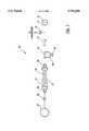
- FIGUREis a schematic representation of a dehumidifier of the present invention.
- a dehumidifier systemis illustrated and generally designated by a reference numeral 10.
- This systemwill be described herein with specific reference to the dehumidification of air, but it will be understood that the system is generally applicable to the dehumidification of other gases or gas mixtures such as hydrogen, carbon dioxide, carbon monoxide, helium, nitrogen, oxygen, argon, hydrogen sulfide, nitronic oxides, ammonia, and hydrocarbons of one to five carbon atoms such as methane, ethane and propane.
- An air compressor or pump 11pressurizes air from the atmosphere which enters the compressor 11 through an inlet 21.
- the pressurized air delivered by the compressor 11is routed past a restrictive device 12, through a check valve 13 and a filtration device 14 with a drain 15 and to a membrane cartridge 17.
- the membrane cartridge 17removes moisture from the pressurized air and routes the dehumidified air through a restrictive device 20 to the inlet of a dry air system 22.
- the membrane cartridge 17utilizes hollow fiber membranes 18 to separate water vapor from air and expel it from the cartridge as water vapor.
- the hollow fiber membranes 18allow certain gases to permeate through the fiber and escape, while other gases continue through the hollow portion of the fiber.
- the hollow fiber membranes 18extend from a cartridge inlet 16 to a cartridge outlet 26 so that only air which travels within the hollows of the fibers 18 is available for induction into the dry air system 22. Gases, such as water vapor, which permeate through the walls of the fibers, exit the cartridge 17 through a weep hole 19.
- the preferred membrane cartridgeis commercially sold under the tradename "Prism Cactus" by Permea Inc., Malvern Industrial Park, Box 396, Malvern, Pa. 19355.
- a Permea membrane cartridge Model PPC21is used.
- gasessuch as water vapor, hydrogen, helium and carbon dioxide permeate the fiber membrane quickly, while gases such as carbon monoxide, nitrogen and methane permeate the fiber membrane slowly. Therefore, more gases, and greater quantities, are filtered out of air as the air spends more time within the membrane cartridge 17. Consequently, as the air spends more time within the membrane cartridge, the air becomes more dehumidified, and the dew point of the air decreases.
- the present inventionpermits decreases in air flow and system pressure due to increased elevation while providing dehumidified air with the desired dew point.
- the decrease in air flowincreases the residence time of the air within the membrane cartridge, resulting in drier air and a reduced dew point in the dehumidified air.
- the pressurized air from the compressor 11flows past a restrictive device such as an orifice 12 which releases excessive air flow from the compressor to the atmosphere.
- the orifice 12may be adjusted manually during assembly to account for differences among compressors. Excessive flow rates result in elevated dew points for the dehumidified air because the air spends less time within the membrane cartridge 17.
- a check valve 13prevents the loss of dehumidified air by allowing air to pass from the compressor 11 to the membrane cartridge 17 but not in the reverse direction, from the membrane cartridge 17 to the compressor 11.
- the pressurized airthen enters the filtration device 14 that removes liquid water from the air. The liquid water is removed from the air to prevent it from possibly saturating the fiber membranes 18 within the membrane cartridge 17.
- Saturated fiber membranescannot filter water vapor from the air, and thus removal of the liquid water prolongs the efficient operation of the membrane cartridge 17.
- the removed waterdrips into a bowl 24 and is drained from the bowl 24 through a drain 15.
- the drain 15preferably includes an automatic float valve so that it is opened only during those intervals when water is being removed from the filter. This design allows for a smaller size compressor 11 by securing the system from unnecessary losses of pressurized air.
- a restrictive device 20such as an orifice is connected to the dehumidified air outlet 26 to link the system pressure and the flow rate together such that the flow rate and pressure combination produce dehumidified air having a desired dew point.
- the dehumidifier 10By designing the dehumidifier 10 with the correct size restrictive device 20, compressor 11 and membrane cartridge 17, the dehumidifier 10 will regulate itself because pressure changes will follow flow rate changes in the desired proportion such that the resulting combination of pressure and flow rate produces dehumidified air having the desired dew point temperature.
- Table 1illustrates the effect of linking system pressure and flow rate using a 0.014 inch orifice.
- a preferred embodiment of the present inventionuses a 0.014 inch orifice.
- the system pressuredecreases because the system pressure and the flow rate are linked by the restrictive device 20.
- the system pressure decreasetends to lower the operating efficiency of the membrane cartridge, but the flow rate decrease increases the residence time of the air within the membrane cartridge.
- the increased residence time of the air within the membrane cartridgelowers the dew point of the dehumidified air and compensates for the decreased efficiency of the membrane cartridge so that the dew point of the dehumidified air is not adversely affected.
- the present inventionmust be designed so that the system pressure and flow rate follow each other properly in order for the dehumidifier to consistently produce air with the proper dew point. For example, if air flow decreases slightly but system pressure drastically falls, the increased residence time of the air within the membrane cartridge will not compensate for the inefficiency of the membrane cartridge at the low pressure, and the dew point of the dehumidified air will rise.
- a dehumidifier that uses a compressor for its air sourcewill experience a decrease in compressor output flow rates with increasing elevation.
- a typical reciprocating oil-less compressorwill develop its rated output flow rate at sea level but only half of its rated output flow rate at an elevation of 10,000 feet, at a given pressure. Due to these flow rate losses, previous dehumidifiers that operated with a constant flow rate required a compressor capable of producing about double the flow rate required at sea level, to enable the same system to operate satisfactorily at 10,000 feet.
- the present inventioncan utilize a smaller compressor with lower output flow rates because the system does not require constant pressure and flow rate.
- the use of a smaller compressornot only reduces cost but also increases reliability and provides a more compact and light weight dehumidifier.
- a Thomas compressor Model #607is used.
- Table 2shows that increasing elevation leads to decreased compressor output flow rate, decreased system pressure and a decreased cartridge outlet dew point temperature. As described above, the present invention regulates itself so that these decreases in system pressure and flow rate do not adversely affect the dew point of the dehumidified air.
- the dehumidifier of the present inventionrequires fewer components because the present invention does not require constant pressure or flow rate regulation. Fewer components result in lower assembly costs and higher reliability. In fact, the self-regulating nature of the present dehumidifier improves system reliability because minor defects in the dehumidifier that cause output flow loss, such as leaks or compressor wear, do not adversely effect the operation of the present invention. If the dehumidifier of the present invention experiences a small unexpected loss of output flow due to leaks or other damage to the dehumidifier, the present invention will maintain an acceptable dew point for the dehumidified air entering the dry air system 22 because the loss of air flow will increase the residence time of the air within the membrane cartridge 11.
- the supply pressure, the flow rate and the size of the membrane cartridgeare selected to supply a particular dry air system 22 with dehumidified air having the desired dew point.
- the present inventionallows the decrease of the flow rate and system pressure while still providing dehumidified air at the appropriate dew point for the dry air system 22.
- the dry air system 22is a tightly sealed system, such as a waveguide system (or other signal transmission media), so that the induction of the pressurized dehumidified air pressurizes the system 22.
- a pressurized systemprevents humid atmospheric air from seeping into the system 22, thereby preserving the low humidity level of the air. Since the dehumidified air cannot rapidly escape from the sealed system 22, the compressor 11 does not need to operate continuously in order to effectively dehumidify the air contained within the system 22. Therefore, in order to optimize the efficiency of the dehumidifier 10, the compressor 11 is operated intermittently. This intermittent operation may be cyclical, using a simple control which automatically switches the compressor 11 on and off at regular time intervals. Alternately, a pressure sensor within the dry air system 22 can trigger the switching on and off of compressor 11.
- the present inventionhas been described with particular reference to controlling the dew point of air, the invention is also applicable to other gases or gas mixtures such as hydrogen, carbon dioxide, carbon monoxide, helium, nitrogen, oxygen, argon, hydrogen sulfide, nitronic oxides, ammonia, and hydrocarbons of one to five carbon atoms such as methane, ethane and propane.
- gases or gas mixturessuch as hydrogen, carbon dioxide, carbon monoxide, helium, nitrogen, oxygen, argon, hydrogen sulfide, nitronic oxides, ammonia, and hydrocarbons of one to five carbon atoms such as methane, ethane and propane.
- the cartridge 17must be provided with a different membrane 18 and/or treatments for certain of these gases, as described for example in U.S. Pat. Nos. 4,230,463; 4,472,175; 4,486,202; 4,575,385; 4,597,777; 4,614,524; 4,654,055 and 4,728,345.
Landscapes
- Chemical & Material Sciences (AREA)
- Engineering & Computer Science (AREA)
- Analytical Chemistry (AREA)
- General Chemical & Material Sciences (AREA)
- Oil, Petroleum & Natural Gas (AREA)
- Chemical Kinetics & Catalysis (AREA)
- Mechanical Engineering (AREA)
- General Engineering & Computer Science (AREA)
- Drying Of Gases (AREA)
- Separation Using Semi-Permeable Membranes (AREA)
Abstract
Description
TABLE 1 ______________________________________ Effect of system pressure across a .014 inch diameter metal orifice SYSTEM SUPPLY TYPICAL OUTLET PRESSURE (PSIG) FLOW RATE (SCFH) ______________________________________ 20 6.0 30 6.7 40 8.2 50 9.6 60 11 70 13 80 15 ______________________________________
TABLE 2 ______________________________________ Effect of elevation to system pressure and cartridge outlet dew point CARTRIDGE CARTRIDGE CARTRIDGE DEHUMIDIFIER OUTLET FEED OUTLET ELEVATION FLOW RATE PRESSURE DEW (FT) (SCFM) (PSIG) POINT (C.) ______________________________________ Sea Level .30 95 -50 4,000 .25 81 -52 8,000 .21 67 -52 12,000 .18 55 -54 ______________________________________
Claims (17)
Priority Applications (7)
| Application Number | Priority Date | Filing Date | Title |
|---|---|---|---|
| US07/981,191US5762690A (en) | 1992-11-25 | 1992-11-25 | Dehumidifier for supplying air using variable flow rate and variable pressure in a membrane dryer |
| CA002102393ACA2102393C (en) | 1992-11-25 | 1993-11-03 | Dehumidifier for supplying air using variable flow rate and variable pressure in a membrane dryer |
| AU50591/93AAU664776B2 (en) | 1992-11-25 | 1993-11-10 | Dehumidifier for supplying air using variable flow rate and variable pressure in a membrane dryer |
| DE69319069TDE69319069T2 (en) | 1992-11-25 | 1993-11-11 | Dehumidifier for air supply using variable flow and pressure in a membrane dryer |
| EP93118293AEP0599149B1 (en) | 1992-11-25 | 1993-11-11 | Dehumidifier for supplying air using variable flow rate and variable pressure in a membrane dryer |
| JP29319193AJP3683287B2 (en) | 1992-11-25 | 1993-11-24 | Apparatus and method for a dehumidification system |
| US08/976,887US5885329A (en) | 1992-11-25 | 1997-11-24 | Dehumidifier for supplying air using variable flow rate and variable pressure in a membrane dryer |
Applications Claiming Priority (1)
| Application Number | Priority Date | Filing Date | Title |
|---|---|---|---|
| US07/981,191US5762690A (en) | 1992-11-25 | 1992-11-25 | Dehumidifier for supplying air using variable flow rate and variable pressure in a membrane dryer |
Related Child Applications (1)
| Application Number | Title | Priority Date | Filing Date |
|---|---|---|---|
| US08/976,887ContinuationUS5885329A (en) | 1992-11-25 | 1997-11-24 | Dehumidifier for supplying air using variable flow rate and variable pressure in a membrane dryer |
Publications (1)
| Publication Number | Publication Date |
|---|---|
| US5762690Atrue US5762690A (en) | 1998-06-09 |
Family
ID=25528189
Family Applications (2)
| Application Number | Title | Priority Date | Filing Date |
|---|---|---|---|
| US07/981,191Expired - LifetimeUS5762690A (en) | 1992-11-25 | 1992-11-25 | Dehumidifier for supplying air using variable flow rate and variable pressure in a membrane dryer |
| US08/976,887Expired - LifetimeUS5885329A (en) | 1992-11-25 | 1997-11-24 | Dehumidifier for supplying air using variable flow rate and variable pressure in a membrane dryer |
Family Applications After (1)
| Application Number | Title | Priority Date | Filing Date |
|---|---|---|---|
| US08/976,887Expired - LifetimeUS5885329A (en) | 1992-11-25 | 1997-11-24 | Dehumidifier for supplying air using variable flow rate and variable pressure in a membrane dryer |
Country Status (6)
| Country | Link |
|---|---|
| US (2) | US5762690A (en) |
| EP (1) | EP0599149B1 (en) |
| JP (1) | JP3683287B2 (en) |
| AU (1) | AU664776B2 (en) |
| CA (1) | CA2102393C (en) |
| DE (1) | DE69319069T2 (en) |
Cited By (6)
| Publication number | Priority date | Publication date | Assignee | Title |
|---|---|---|---|---|
| US6370887B1 (en)* | 1999-09-03 | 2002-04-16 | Nabco Ltd | Compressed air dehumidifier and a dehumidification device and a modified system for these |
| US6491739B1 (en)* | 1999-11-09 | 2002-12-10 | Litton Systems, Inc. | Air separation module using a fast start valve for fast warm up of a permeable membrane air separation module |
| US20070039464A1 (en)* | 2005-08-17 | 2007-02-22 | Andrew Corporation | Dry gas production systems for pressurizing a space and methods of operating such systems to produce a dry gas stream |
| US20100077784A1 (en)* | 2007-01-30 | 2010-04-01 | Smc Corporation | Dehumidification type air system |
| US20110077605A1 (en)* | 2005-07-14 | 2011-03-31 | Boehringer Technologies, L.P. | Pump system for negative pressure wound therapy |
| US20160221039A1 (en)* | 2015-01-30 | 2016-08-04 | At&T Intellectual Property I, Lp | Method and apparatus for mitigating interference affecting a propagation of electromagnetic waves guided by a transmission medium |
Families Citing this family (15)
| Publication number | Priority date | Publication date | Assignee | Title |
|---|---|---|---|---|
| AUPM592694A0 (en)* | 1994-05-30 | 1994-06-23 | F F Seeley Nominees Pty Ltd | Vacuum dewatering of desiccant brines |
| CA2335424A1 (en)* | 1998-06-17 | 1999-12-23 | Kunitaka Mizobe | Method of and apparatus for testing airtightness of closed space provided with steam movement control device |
| US6126724A (en)* | 1999-02-19 | 2000-10-03 | Hansen Inc. | Locomotive air processing apparatus |
| NL1011626C2 (en) | 1999-03-22 | 2000-09-27 | Kema Nv | Preparation of water from flue gases. |
| US6705092B1 (en)* | 2001-11-14 | 2004-03-16 | Honeywell International Inc. | Vapor membrane dehumidification for air cycle environment control system |
| US6719825B2 (en)* | 2002-05-07 | 2004-04-13 | Graham-White Manufacturing Company | Air drying apparatus and method |
| US6764529B2 (en)* | 2002-07-01 | 2004-07-20 | Bendix Commercial Vehicle Systems Llc | Membrane gas dehydrating apparatus for gas controlled and powered systems |
| US6881245B2 (en)* | 2002-10-18 | 2005-04-19 | Bendix Commercial Vehicle Systems Llc | Membrane air dryer and method of mounting a membrane dryer to a vehicle |
| US6923845B2 (en)* | 2002-10-18 | 2005-08-02 | Bendix Commercial Vehicle Systems Llc | Membrane air dryer for vehicle air brake system |
| FR2862129A1 (en)* | 2003-11-07 | 2005-05-13 | Olivier Kaelbel | Granulated thermoplastic material drying process for injection machine, involves circulating compressed air via filtration units then via membrane separator of drying units, expanding dry air from separator and heating air |
| DE102004022312B4 (en)* | 2004-05-04 | 2009-04-16 | Daimler Ag | Moisture exchange module with a bundle of moisture permeable hollow fiber membranes |
| US7678177B2 (en)* | 2006-09-12 | 2010-03-16 | New York Air Brake Corporation | Membrane air dryer and sweep valve |
| JP5982876B2 (en)* | 2012-02-29 | 2016-08-31 | 宇部興産株式会社 | Gas separation system |
| JP2014091766A (en)* | 2012-11-01 | 2014-05-19 | Ube Ind Ltd | System for utilizing biogas, and method for dehumidifying biogas |
| US11619405B1 (en) | 2022-01-27 | 2023-04-04 | Greg Drenik | Airflow moisture reduction system |
Citations (63)
| Publication number | Priority date | Publication date | Assignee | Title |
|---|---|---|---|---|
| US2779173A (en)* | 1955-04-25 | 1957-01-29 | Gen Motors Corp | Dehumidifier having unitary evaporator-condenser plate |
| US3133132A (en)* | 1960-11-29 | 1964-05-12 | Univ California | High flow porous membranes for separating water from saline solutions |
| US3499062A (en)* | 1965-12-22 | 1970-03-03 | Du Pont | Method of repairing leaks in fluid separation apparatus |
| US3511031A (en)* | 1968-03-19 | 1970-05-12 | Little Inc A | Apparatus for removing water vapor from gases |
| US3536611A (en)* | 1967-02-06 | 1970-10-27 | Abcor Inc | Membrane device and method |
| DE1919290A1 (en)* | 1969-04-16 | 1970-10-29 | Schantz Dipl Ing Hugo | Use of a cooling unit for air drying and heat recovery in an indoor swimming pool or sauna |
| US3556992A (en)* | 1969-07-22 | 1971-01-19 | Amicon Corp | Anisotropic ultrafiltration membrane having adhering coating and methods of forming and using this membrane |
| US3556305A (en)* | 1968-03-28 | 1971-01-19 | Amicon Corp | Composite membrane and process for making same |
| US3580841A (en)* | 1969-07-31 | 1971-05-25 | Us Interior | Ultrathin semipermeable membrane |
| US3615024A (en)* | 1968-08-26 | 1971-10-26 | Amicon Corp | High flow membrane |
| US3616607A (en)* | 1970-04-06 | 1971-11-02 | Northern Natural Gas Co | Separation of nitrogen and methane containing gas mixtures |
| US3657113A (en)* | 1970-02-03 | 1972-04-18 | Mobil Oil Corp | Separating fluids with selective membranes |
| US3676203A (en)* | 1970-08-07 | 1972-07-11 | Us Interior | Semipermeable membranes |
| US3735559A (en)* | 1972-02-02 | 1973-05-29 | Gen Electric | Sulfonated polyxylylene oxide as a permselective membrane for water vapor transport |
| US3735558A (en)* | 1971-06-29 | 1973-05-29 | Perma Pure Process Inc | Process for separating fluids and apparatus |
| US3775303A (en)* | 1971-12-08 | 1973-11-27 | Gulf Research Development Co | Production of low sulfur asphaltic fuel oil |
| US3874986A (en)* | 1974-05-20 | 1975-04-01 | Gen Electric | Laminated porous/non-porous membranes |
| US3892665A (en)* | 1973-10-15 | 1975-07-01 | Standard Oil Co | Membrane method and product |
| US3899309A (en)* | 1972-07-20 | 1975-08-12 | Du Pont | Aromatic polyimide, polyester and polyamide separation membranes |
| US3922149A (en)* | 1974-01-30 | 1975-11-25 | Garrett Corp | Oxygen air enrichment method |
| US3930814A (en)* | 1974-11-27 | 1976-01-06 | General Electric Company | Process for producing oxygen-enriched gas |
| US4108765A (en)* | 1975-12-01 | 1978-08-22 | Monsanto Company | Membrane separation of methanol from formaldehyde aqueous mixtures |
| US4142966A (en)* | 1974-04-01 | 1979-03-06 | Monsanto Company | Membrane separation of water from aqueous mixtures |
| US4157960A (en)* | 1977-11-30 | 1979-06-12 | Monsanto Company | Method for enhancing membrane separation |
| US4230463A (en)* | 1977-09-13 | 1980-10-28 | Monsanto Company | Multicomponent membranes for gas separations |
| EP0030863A1 (en)* | 1979-12-14 | 1981-06-24 | Hei Co.,Ltd | An exchange element for a heat and/or moisture exchange and an exchanger for heat and/or moisture |
| US4311594A (en)* | 1975-12-01 | 1982-01-19 | Monsanto Company | Membrane separation of organics from aqueous solutions |
| EP0051469A1 (en)* | 1980-11-03 | 1982-05-12 | Monsanto Company | Process for separating a gas from a mixture of gases |
| US4397661A (en)* | 1980-06-27 | 1983-08-09 | Monsanto Company | Gas permeation apparatus having permeate rate controlled valving |
| US4421529A (en)* | 1982-07-02 | 1983-12-20 | The Dow Chemical Company | Membrane system for intermittent gas separation |
| US4472175A (en)* | 1983-06-30 | 1984-09-18 | Monsanto Company | Asymmetric gas separation membranes |
| US4486202A (en)* | 1983-06-30 | 1984-12-04 | Monsanto Company | Asymmetric gas separation membranes |
| US4497640A (en)* | 1983-02-04 | 1985-02-05 | Compagnie Francaise De Petroles | Process for the dehydration of gases containing hydrocarbons |
| US4549888A (en)* | 1984-11-07 | 1985-10-29 | Allied Corporation | Automatic control for an external air supply |
| JPS60238119A (en)* | 1984-05-10 | 1985-11-27 | Takuma Sogo Kenkyusho:Kk | Air dehumidification apparatus |
| US4575385A (en)* | 1983-06-30 | 1986-03-11 | Monsanto Company | Permeation modified gas separation membranes |
| US4583996A (en)* | 1983-11-04 | 1986-04-22 | Kabushiki Kaisha Toyota Chuo Kenkyusho | Apparatus for separating condensable gas |
| US4597777A (en)* | 1983-02-15 | 1986-07-01 | Monsanto Company | Membrane gas separation processes |
| US4614524A (en)* | 1984-12-31 | 1986-09-30 | Monsanto Company | Water-free hydrocarbon separation membrane and process |
| SU1271522A1 (en)* | 1983-11-09 | 1986-11-23 | Саратовский Государственный Ордена Трудового Красного Знамени Медицинский Институт | Method of differential diagnosis of tuberculosis and nonspecific diseases of the lungs |
| JPS6242723A (en)* | 1985-08-20 | 1987-02-24 | Ube Ind Ltd | Mixed gas dehumidification method |
| US4654055A (en)* | 1983-06-30 | 1987-03-31 | Monsanto Company | Asymmetric gas separation membranes |
| US4685941A (en)* | 1984-11-20 | 1987-08-11 | Tokico Ltd. | Compressed air supplying device |
| US4687578A (en)* | 1985-12-12 | 1987-08-18 | Monsanto Company | Fluid separation membranes |
| JPS62191404A (en)* | 1986-02-19 | 1987-08-21 | Hitachi Ltd | Air separation apparatus |
| JPS62273028A (en)* | 1986-05-20 | 1987-11-27 | Asahi Chem Ind Co Ltd | Gas dehumidifier |
| US4718921A (en)* | 1986-10-08 | 1988-01-12 | Ube Industries, Ltd. | Method for removing water vapor from water vapor-containing gas |
| US4728345A (en)* | 1983-12-28 | 1988-03-01 | Monsanto Company | Multicomponent gas separation membranes having polyphosphazene coatings |
| JPS63123421A (en)* | 1986-11-10 | 1988-05-27 | Kuraray Co Ltd | Dehumidified air feeder |
| JPS63123422A (en)* | 1986-11-11 | 1988-05-27 | Kuraray Co Ltd | Dehumidified air feeder |
| JPS63236517A (en)* | 1987-03-24 | 1988-10-03 | Ube Ind Ltd | Mixed gas dehumidification method |
| US4783201A (en)* | 1987-12-28 | 1988-11-08 | Rice Arthur W | Gas dehydration membrane apparatus |
| JPS63296819A (en)* | 1987-05-28 | 1988-12-02 | Matsushita Electric Ind Co Ltd | Method for enriching gas supplied to chamber |
| US4806132A (en)* | 1987-06-23 | 1989-02-21 | Union Carbide Corporation | Turndown control method for membrane separation systems |
| US4813474A (en)* | 1986-12-26 | 1989-03-21 | Kabushiki Kaisha Toshiba | Air conditioner apparatus with improved dehumidification control |
| US4844719A (en)* | 1985-02-09 | 1989-07-04 | Asahi Kasei Kogyo Kabushiki Kaisha | Permeable polymer membrane for dessication of gas |
| US4857082A (en)* | 1988-09-15 | 1989-08-15 | Air Products And Chemicals, Inc. | Membrane unit turn-down control system |
| US4863492A (en)* | 1988-11-28 | 1989-09-05 | Uop | Integrated membrane/PSA process and system |
| US4944776A (en)* | 1989-10-05 | 1990-07-31 | Andrew Corporation | Dehumidifier for waveguide system |
| US5030251A (en)* | 1989-10-30 | 1991-07-09 | Permea, Inc. | System and method for separating a portion of a gas from a mixture of gases |
| US5053058A (en)* | 1989-12-29 | 1991-10-01 | Uop | Control process and apparatus for membrane separation systems |
| US5118327A (en)* | 1989-10-05 | 1992-06-02 | Andrew Corporation | Dehumidifier for supplying gas having controlled dew point |
| US5131929A (en)* | 1991-05-06 | 1992-07-21 | Permea, Inc. | Pressure control for improved gas dehydration in systems which employ membrane dryers in intermittent service |
Family Cites Families (7)
| Publication number | Priority date | Publication date | Assignee | Title |
|---|---|---|---|---|
| FR2403819A1 (en)* | 1977-09-27 | 1979-04-20 | Ravier Philippe | GAS SEPARATION PROCESS AND INSTALLATION BY GAS DIFFUSION |
| GB8916510D0 (en)* | 1989-07-19 | 1989-09-06 | Boc Group Plc | Separation of gas mixtures |
| US5108464A (en)* | 1989-09-19 | 1992-04-28 | Bend Research, Inc. | Countercurrent dehydration by hollow fibers |
| US5129924A (en)* | 1989-12-29 | 1992-07-14 | Jerald Schultz | Supplemental oxygen ventilator |
| US5281253A (en)* | 1993-01-06 | 1994-01-25 | Praxair Technology, Inc. | Multistage membrane control system and process |
| DE4435702C2 (en)* | 1994-10-06 | 1998-11-26 | Druckluft Dannoehl Gmbh | Method and device for producing nitrogen |
| US5681368A (en)* | 1995-07-05 | 1997-10-28 | Andrew Corporation | Dehumidifier system using membrane cartridge |
- 1992
- 1992-11-25USUS07/981,191patent/US5762690A/ennot_activeExpired - Lifetime
- 1993
- 1993-11-03CACA002102393Apatent/CA2102393C/ennot_activeExpired - Lifetime
- 1993-11-10AUAU50591/93Apatent/AU664776B2/ennot_activeExpired
- 1993-11-11DEDE69319069Tpatent/DE69319069T2/ennot_activeExpired - Lifetime
- 1993-11-11EPEP93118293Apatent/EP0599149B1/ennot_activeExpired - Lifetime
- 1993-11-24JPJP29319193Apatent/JP3683287B2/ennot_activeExpired - Lifetime
- 1997
- 1997-11-24USUS08/976,887patent/US5885329A/ennot_activeExpired - Lifetime
Patent Citations (63)
| Publication number | Priority date | Publication date | Assignee | Title |
|---|---|---|---|---|
| US2779173A (en)* | 1955-04-25 | 1957-01-29 | Gen Motors Corp | Dehumidifier having unitary evaporator-condenser plate |
| US3133132A (en)* | 1960-11-29 | 1964-05-12 | Univ California | High flow porous membranes for separating water from saline solutions |
| US3499062A (en)* | 1965-12-22 | 1970-03-03 | Du Pont | Method of repairing leaks in fluid separation apparatus |
| US3536611A (en)* | 1967-02-06 | 1970-10-27 | Abcor Inc | Membrane device and method |
| US3511031A (en)* | 1968-03-19 | 1970-05-12 | Little Inc A | Apparatus for removing water vapor from gases |
| US3556305A (en)* | 1968-03-28 | 1971-01-19 | Amicon Corp | Composite membrane and process for making same |
| US3615024A (en)* | 1968-08-26 | 1971-10-26 | Amicon Corp | High flow membrane |
| DE1919290A1 (en)* | 1969-04-16 | 1970-10-29 | Schantz Dipl Ing Hugo | Use of a cooling unit for air drying and heat recovery in an indoor swimming pool or sauna |
| US3556992A (en)* | 1969-07-22 | 1971-01-19 | Amicon Corp | Anisotropic ultrafiltration membrane having adhering coating and methods of forming and using this membrane |
| US3580841A (en)* | 1969-07-31 | 1971-05-25 | Us Interior | Ultrathin semipermeable membrane |
| US3657113A (en)* | 1970-02-03 | 1972-04-18 | Mobil Oil Corp | Separating fluids with selective membranes |
| US3616607A (en)* | 1970-04-06 | 1971-11-02 | Northern Natural Gas Co | Separation of nitrogen and methane containing gas mixtures |
| US3676203A (en)* | 1970-08-07 | 1972-07-11 | Us Interior | Semipermeable membranes |
| US3735558A (en)* | 1971-06-29 | 1973-05-29 | Perma Pure Process Inc | Process for separating fluids and apparatus |
| US3775303A (en)* | 1971-12-08 | 1973-11-27 | Gulf Research Development Co | Production of low sulfur asphaltic fuel oil |
| US3735559A (en)* | 1972-02-02 | 1973-05-29 | Gen Electric | Sulfonated polyxylylene oxide as a permselective membrane for water vapor transport |
| US3899309A (en)* | 1972-07-20 | 1975-08-12 | Du Pont | Aromatic polyimide, polyester and polyamide separation membranes |
| US3892665A (en)* | 1973-10-15 | 1975-07-01 | Standard Oil Co | Membrane method and product |
| US3922149A (en)* | 1974-01-30 | 1975-11-25 | Garrett Corp | Oxygen air enrichment method |
| US4142966A (en)* | 1974-04-01 | 1979-03-06 | Monsanto Company | Membrane separation of water from aqueous mixtures |
| US3874986A (en)* | 1974-05-20 | 1975-04-01 | Gen Electric | Laminated porous/non-porous membranes |
| US3930814A (en)* | 1974-11-27 | 1976-01-06 | General Electric Company | Process for producing oxygen-enriched gas |
| US4108765A (en)* | 1975-12-01 | 1978-08-22 | Monsanto Company | Membrane separation of methanol from formaldehyde aqueous mixtures |
| US4311594A (en)* | 1975-12-01 | 1982-01-19 | Monsanto Company | Membrane separation of organics from aqueous solutions |
| US4230463A (en)* | 1977-09-13 | 1980-10-28 | Monsanto Company | Multicomponent membranes for gas separations |
| US4157960A (en)* | 1977-11-30 | 1979-06-12 | Monsanto Company | Method for enhancing membrane separation |
| EP0030863A1 (en)* | 1979-12-14 | 1981-06-24 | Hei Co.,Ltd | An exchange element for a heat and/or moisture exchange and an exchanger for heat and/or moisture |
| US4397661A (en)* | 1980-06-27 | 1983-08-09 | Monsanto Company | Gas permeation apparatus having permeate rate controlled valving |
| EP0051469A1 (en)* | 1980-11-03 | 1982-05-12 | Monsanto Company | Process for separating a gas from a mixture of gases |
| US4421529A (en)* | 1982-07-02 | 1983-12-20 | The Dow Chemical Company | Membrane system for intermittent gas separation |
| US4497640A (en)* | 1983-02-04 | 1985-02-05 | Compagnie Francaise De Petroles | Process for the dehydration of gases containing hydrocarbons |
| US4597777A (en)* | 1983-02-15 | 1986-07-01 | Monsanto Company | Membrane gas separation processes |
| US4472175A (en)* | 1983-06-30 | 1984-09-18 | Monsanto Company | Asymmetric gas separation membranes |
| US4575385A (en)* | 1983-06-30 | 1986-03-11 | Monsanto Company | Permeation modified gas separation membranes |
| US4486202A (en)* | 1983-06-30 | 1984-12-04 | Monsanto Company | Asymmetric gas separation membranes |
| US4654055A (en)* | 1983-06-30 | 1987-03-31 | Monsanto Company | Asymmetric gas separation membranes |
| US4583996A (en)* | 1983-11-04 | 1986-04-22 | Kabushiki Kaisha Toyota Chuo Kenkyusho | Apparatus for separating condensable gas |
| SU1271522A1 (en)* | 1983-11-09 | 1986-11-23 | Саратовский Государственный Ордена Трудового Красного Знамени Медицинский Институт | Method of differential diagnosis of tuberculosis and nonspecific diseases of the lungs |
| US4728345A (en)* | 1983-12-28 | 1988-03-01 | Monsanto Company | Multicomponent gas separation membranes having polyphosphazene coatings |
| JPS60238119A (en)* | 1984-05-10 | 1985-11-27 | Takuma Sogo Kenkyusho:Kk | Air dehumidification apparatus |
| US4549888A (en)* | 1984-11-07 | 1985-10-29 | Allied Corporation | Automatic control for an external air supply |
| US4685941A (en)* | 1984-11-20 | 1987-08-11 | Tokico Ltd. | Compressed air supplying device |
| US4614524A (en)* | 1984-12-31 | 1986-09-30 | Monsanto Company | Water-free hydrocarbon separation membrane and process |
| US4844719A (en)* | 1985-02-09 | 1989-07-04 | Asahi Kasei Kogyo Kabushiki Kaisha | Permeable polymer membrane for dessication of gas |
| JPS6242723A (en)* | 1985-08-20 | 1987-02-24 | Ube Ind Ltd | Mixed gas dehumidification method |
| US4687578A (en)* | 1985-12-12 | 1987-08-18 | Monsanto Company | Fluid separation membranes |
| JPS62191404A (en)* | 1986-02-19 | 1987-08-21 | Hitachi Ltd | Air separation apparatus |
| JPS62273028A (en)* | 1986-05-20 | 1987-11-27 | Asahi Chem Ind Co Ltd | Gas dehumidifier |
| US4718921A (en)* | 1986-10-08 | 1988-01-12 | Ube Industries, Ltd. | Method for removing water vapor from water vapor-containing gas |
| JPS63123421A (en)* | 1986-11-10 | 1988-05-27 | Kuraray Co Ltd | Dehumidified air feeder |
| JPS63123422A (en)* | 1986-11-11 | 1988-05-27 | Kuraray Co Ltd | Dehumidified air feeder |
| US4813474A (en)* | 1986-12-26 | 1989-03-21 | Kabushiki Kaisha Toshiba | Air conditioner apparatus with improved dehumidification control |
| JPS63236517A (en)* | 1987-03-24 | 1988-10-03 | Ube Ind Ltd | Mixed gas dehumidification method |
| JPS63296819A (en)* | 1987-05-28 | 1988-12-02 | Matsushita Electric Ind Co Ltd | Method for enriching gas supplied to chamber |
| US4806132A (en)* | 1987-06-23 | 1989-02-21 | Union Carbide Corporation | Turndown control method for membrane separation systems |
| US4783201A (en)* | 1987-12-28 | 1988-11-08 | Rice Arthur W | Gas dehydration membrane apparatus |
| US4857082A (en)* | 1988-09-15 | 1989-08-15 | Air Products And Chemicals, Inc. | Membrane unit turn-down control system |
| US4863492A (en)* | 1988-11-28 | 1989-09-05 | Uop | Integrated membrane/PSA process and system |
| US4944776A (en)* | 1989-10-05 | 1990-07-31 | Andrew Corporation | Dehumidifier for waveguide system |
| US5118327A (en)* | 1989-10-05 | 1992-06-02 | Andrew Corporation | Dehumidifier for supplying gas having controlled dew point |
| US5030251A (en)* | 1989-10-30 | 1991-07-09 | Permea, Inc. | System and method for separating a portion of a gas from a mixture of gases |
| US5053058A (en)* | 1989-12-29 | 1991-10-01 | Uop | Control process and apparatus for membrane separation systems |
| US5131929A (en)* | 1991-05-06 | 1992-07-21 | Permea, Inc. | Pressure control for improved gas dehydration in systems which employ membrane dryers in intermittent service |
Cited By (10)
| Publication number | Priority date | Publication date | Assignee | Title |
|---|---|---|---|---|
| US6370887B1 (en)* | 1999-09-03 | 2002-04-16 | Nabco Ltd | Compressed air dehumidifier and a dehumidification device and a modified system for these |
| US6491739B1 (en)* | 1999-11-09 | 2002-12-10 | Litton Systems, Inc. | Air separation module using a fast start valve for fast warm up of a permeable membrane air separation module |
| US20110077605A1 (en)* | 2005-07-14 | 2011-03-31 | Boehringer Technologies, L.P. | Pump system for negative pressure wound therapy |
| US20070039464A1 (en)* | 2005-08-17 | 2007-02-22 | Andrew Corporation | Dry gas production systems for pressurizing a space and methods of operating such systems to produce a dry gas stream |
| US7481869B2 (en) | 2005-08-17 | 2009-01-27 | Andrew Llc | Dry gas production systems for pressurizing a space and methods of operating such systems to produce a dry gas stream |
| US20100077784A1 (en)* | 2007-01-30 | 2010-04-01 | Smc Corporation | Dehumidification type air system |
| US8133307B2 (en)* | 2007-01-30 | 2012-03-13 | Smc Corporation | Dehumidification type air system |
| US20160221039A1 (en)* | 2015-01-30 | 2016-08-04 | At&T Intellectual Property I, Lp | Method and apparatus for mitigating interference affecting a propagation of electromagnetic waves guided by a transmission medium |
| US10144036B2 (en)* | 2015-01-30 | 2018-12-04 | At&T Intellectual Property I, L.P. | Method and apparatus for mitigating interference affecting a propagation of electromagnetic waves guided by a transmission medium |
| US10583463B2 (en) | 2015-01-30 | 2020-03-10 | At&T Intellectual Property I, L.P. | Method and apparatus for mitigating interference affecting a propagation of electromagnetic waves guided by a transmission medium |
Also Published As
| Publication number | Publication date |
|---|---|
| EP0599149B1 (en) | 1998-06-10 |
| US5885329A (en) | 1999-03-23 |
| JPH06218220A (en) | 1994-08-09 |
| AU664776B2 (en) | 1995-11-30 |
| JP3683287B2 (en) | 2005-08-17 |
| DE69319069D1 (en) | 1998-07-16 |
| EP0599149A2 (en) | 1994-06-01 |
| EP0599149A3 (en) | 1995-03-08 |
| CA2102393C (en) | 2000-06-06 |
| CA2102393A1 (en) | 1994-05-26 |
| DE69319069T2 (en) | 1998-10-08 |
| AU5059193A (en) | 1994-06-09 |
Similar Documents
| Publication | Publication Date | Title |
|---|---|---|
| US5762690A (en) | Dehumidifier for supplying air using variable flow rate and variable pressure in a membrane dryer | |
| US5681368A (en) | Dehumidifier system using membrane cartridge | |
| US5118327A (en) | Dehumidifier for supplying gas having controlled dew point | |
| US4944776A (en) | Dehumidifier for waveguide system | |
| AU749819B2 (en) | Membrane air dryer with scheme to reduce air lost as sweep air | |
| US5605564A (en) | Membrane gas dehydrator | |
| US5383956A (en) | Start-up and shut down processes for membrane systems and membrane systems useful for the same | |
| US5281253A (en) | Multistage membrane control system and process | |
| EP1235631A1 (en) | Compressed gas systems utilizing a variable pressure membrane air drier, and method of operation thereof | |
| CA2104808C (en) | Fast response high purity membrane nitrogen generator | |
| RU2056689C1 (en) | Plant for keeping gas-filled cables under gage pressure | |
| RU2133513C1 (en) | Plant for holding telephone cables under gage pressure | |
| EP3574977B1 (en) | Gas dehydration membrane module with integral filter | |
| JP4451770B2 (en) | Gas-liquid separator and analyzer using the same | |
| JP2000334253A (en) | Compressed air supply system for the plant | |
| RU2171513C1 (en) | Arrangement for holding telephone and gas-filled power cables under gage pressure | |
| HK1027771A (en) | Membrane air dryer with scheme to reduce air lost as sweep air | |
| KR930005622B1 (en) | Improved membrane seperation system and process thereof | |
| JP2003251135A (en) | Dehumidifying apparatus | |
| JP2000051639A (en) | Membrane type gas drier |
Legal Events
| Date | Code | Title | Description |
|---|---|---|---|
| AS | Assignment | Owner name:ANDREW CORPORATION, ILLINOIS Free format text:ASSIGNMENT OF ASSIGNORS INTEREST.;ASSIGNOR:HERMANN, KERSTAN G.;REEL/FRAME:006421/0318 Effective date:19921209 | |
| STCF | Information on status: patent grant | Free format text:PATENTED CASE | |
| FPAY | Fee payment | Year of fee payment:4 | |
| FPAY | Fee payment | Year of fee payment:8 | |
| AS | Assignment | Owner name:BANK OF AMERICA, N.A., AS ADMINISTRATIVE AGENT, CA Free format text:SECURITY AGREEMENT;ASSIGNORS:COMMSCOPE, INC. OF NORTH CAROLINA;ALLEN TELECOM, LLC;ANDREW CORPORATION;REEL/FRAME:020362/0241 Effective date:20071227 Owner name:BANK OF AMERICA, N.A., AS ADMINISTRATIVE AGENT,CAL Free format text:SECURITY AGREEMENT;ASSIGNORS:COMMSCOPE, INC. OF NORTH CAROLINA;ALLEN TELECOM, LLC;ANDREW CORPORATION;REEL/FRAME:020362/0241 Effective date:20071227 | |
| AS | Assignment | Owner name:ANDREW LLC, NORTH CAROLINA Free format text:CHANGE OF NAME;ASSIGNOR:ANDREW CORPORATION;REEL/FRAME:021805/0044 Effective date:20080827 | |
| FPAY | Fee payment | Year of fee payment:12 | |
| AS | Assignment | Owner name:ANDREW LLC (F/K/A ANDREW CORPORATION), NORTH CAROL Free format text:PATENT RELEASE;ASSIGNOR:BANK OF AMERICA, N.A., AS ADMINISTRATIVE AGENT;REEL/FRAME:026039/0005 Effective date:20110114 Owner name:COMMSCOPE, INC. OF NORTH CAROLINA, NORTH CAROLINA Free format text:PATENT RELEASE;ASSIGNOR:BANK OF AMERICA, N.A., AS ADMINISTRATIVE AGENT;REEL/FRAME:026039/0005 Effective date:20110114 Owner name:ALLEN TELECOM LLC, NORTH CAROLINA Free format text:PATENT RELEASE;ASSIGNOR:BANK OF AMERICA, N.A., AS ADMINISTRATIVE AGENT;REEL/FRAME:026039/0005 Effective date:20110114 | |
| AS | Assignment | Owner name:JPMORGAN CHASE BANK, N.A., AS COLLATERAL AGENT, NE Free format text:SECURITY AGREEMENT;ASSIGNORS:ALLEN TELECOM LLC, A DELAWARE LLC;ANDREW LLC, A DELAWARE LLC;COMMSCOPE, INC. OF NORTH CAROLINA, A NORTH CAROLINA CORPORATION;REEL/FRAME:026276/0363 Effective date:20110114 | |
| AS | Assignment | Owner name:JPMORGAN CHASE BANK, N.A., AS COLLATERAL AGENT, NE Free format text:SECURITY AGREEMENT;ASSIGNORS:ALLEN TELECOM LLC, A DELAWARE LLC;ANDREW LLC, A DELAWARE LLC;COMMSCOPE, INC OF NORTH CAROLINA, A NORTH CAROLINA CORPORATION;REEL/FRAME:026272/0543 Effective date:20110114 | |
| AS | Assignment | Owner name:COMMSCOPE TECHNOLOGIES LLC, NORTH CAROLINA Free format text:CHANGE OF NAME;ASSIGNOR:ANDREW LLC;REEL/FRAME:035226/0949 Effective date:20150301 | |
| AS | Assignment | Owner name:WILMINGTON TRUST, NATIONAL ASSOCIATION, AS COLLATERAL AGENT, CONNECTICUT Free format text:SECURITY INTEREST;ASSIGNORS:ALLEN TELECOM LLC;COMMSCOPE TECHNOLOGIES LLC;COMMSCOPE, INC. OF NORTH CAROLINA;AND OTHERS;REEL/FRAME:036201/0283 Effective date:20150611 Owner name:WILMINGTON TRUST, NATIONAL ASSOCIATION, AS COLLATE Free format text:SECURITY INTEREST;ASSIGNORS:ALLEN TELECOM LLC;COMMSCOPE TECHNOLOGIES LLC;COMMSCOPE, INC. OF NORTH CAROLINA;AND OTHERS;REEL/FRAME:036201/0283 Effective date:20150611 | |
| AS | Assignment | Owner name:ALLEN TELECOM LLC, NORTH CAROLINA Free format text:RELEASE OF SECURITY INTEREST PATENTS (RELEASES RF 036201/0283);ASSIGNOR:WILMINGTON TRUST, NATIONAL ASSOCIATION;REEL/FRAME:042126/0434 Effective date:20170317 Owner name:COMMSCOPE TECHNOLOGIES LLC, NORTH CAROLINA Free format text:RELEASE OF SECURITY INTEREST PATENTS (RELEASES RF 036201/0283);ASSIGNOR:WILMINGTON TRUST, NATIONAL ASSOCIATION;REEL/FRAME:042126/0434 Effective date:20170317 Owner name:REDWOOD SYSTEMS, INC., NORTH CAROLINA Free format text:RELEASE OF SECURITY INTEREST PATENTS (RELEASES RF 036201/0283);ASSIGNOR:WILMINGTON TRUST, NATIONAL ASSOCIATION;REEL/FRAME:042126/0434 Effective date:20170317 Owner name:COMMSCOPE, INC. OF NORTH CAROLINA, NORTH CAROLINA Free format text:RELEASE OF SECURITY INTEREST PATENTS (RELEASES RF 036201/0283);ASSIGNOR:WILMINGTON TRUST, NATIONAL ASSOCIATION;REEL/FRAME:042126/0434 Effective date:20170317 | |
| AS | Assignment | Owner name:COMMSCOPE TECHNOLOGIES LLC, NORTH CAROLINA Free format text:RELEASE BY SECURED PARTY;ASSIGNOR:JPMORGAN CHASE BANK, N.A.;REEL/FRAME:048840/0001 Effective date:20190404 Owner name:REDWOOD SYSTEMS, INC., NORTH CAROLINA Free format text:RELEASE BY SECURED PARTY;ASSIGNOR:JPMORGAN CHASE BANK, N.A.;REEL/FRAME:048840/0001 Effective date:20190404 Owner name:COMMSCOPE, INC. OF NORTH CAROLINA, NORTH CAROLINA Free format text:RELEASE BY SECURED PARTY;ASSIGNOR:JPMORGAN CHASE BANK, N.A.;REEL/FRAME:048840/0001 Effective date:20190404 Owner name:ANDREW LLC, NORTH CAROLINA Free format text:RELEASE BY SECURED PARTY;ASSIGNOR:JPMORGAN CHASE BANK, N.A.;REEL/FRAME:048840/0001 Effective date:20190404 Owner name:ALLEN TELECOM LLC, ILLINOIS Free format text:RELEASE BY SECURED PARTY;ASSIGNOR:JPMORGAN CHASE BANK, N.A.;REEL/FRAME:048840/0001 Effective date:20190404 Owner name:COMMSCOPE, INC. OF NORTH CAROLINA, NORTH CAROLINA Free format text:RELEASE BY SECURED PARTY;ASSIGNOR:JPMORGAN CHASE BANK, N.A.;REEL/FRAME:049260/0001 Effective date:20190404 Owner name:ANDREW LLC, NORTH CAROLINA Free format text:RELEASE BY SECURED PARTY;ASSIGNOR:JPMORGAN CHASE BANK, N.A.;REEL/FRAME:049260/0001 Effective date:20190404 Owner name:ALLEN TELECOM LLC, ILLINOIS Free format text:RELEASE BY SECURED PARTY;ASSIGNOR:JPMORGAN CHASE BANK, N.A.;REEL/FRAME:049260/0001 Effective date:20190404 Owner name:REDWOOD SYSTEMS, INC., NORTH CAROLINA Free format text:RELEASE BY SECURED PARTY;ASSIGNOR:JPMORGAN CHASE BANK, N.A.;REEL/FRAME:049260/0001 Effective date:20190404 Owner name:COMMSCOPE TECHNOLOGIES LLC, NORTH CAROLINA Free format text:RELEASE BY SECURED PARTY;ASSIGNOR:JPMORGAN CHASE BANK, N.A.;REEL/FRAME:049260/0001 Effective date:20190404 |