US5762632A - Infusion set - Google Patents
Infusion setDownload PDFInfo
- Publication number
- US5762632A US5762632AUS08/617,772US61777296AUS5762632AUS 5762632 AUS5762632 AUS 5762632AUS 61777296 AUS61777296 AUS 61777296AUS 5762632 AUS5762632 AUS 5762632A
- Authority
- US
- United States
- Prior art keywords
- needle
- base
- infusion set
- movement
- housing
- Prior art date
- Legal status (The legal status is an assumption and is not a legal conclusion. Google has not performed a legal analysis and makes no representation as to the accuracy of the status listed.)
- Expired - Fee Related
Links
Images


Classifications
- A—HUMAN NECESSITIES
- A61—MEDICAL OR VETERINARY SCIENCE; HYGIENE
- A61M—DEVICES FOR INTRODUCING MEDIA INTO, OR ONTO, THE BODY; DEVICES FOR TRANSDUCING BODY MEDIA OR FOR TAKING MEDIA FROM THE BODY; DEVICES FOR PRODUCING OR ENDING SLEEP OR STUPOR
- A61M25/00—Catheters; Hollow probes
- A61M25/01—Introducing, guiding, advancing, emplacing or holding catheters
- A61M25/06—Body-piercing guide needles or the like
- A61M25/0612—Devices for protecting the needle; Devices to help insertion of the needle, e.g. wings or holders
- A61M25/0637—Butterfly or winged devices, e.g. for facilitating handling or for attachment to the skin
- A—HUMAN NECESSITIES
- A61—MEDICAL OR VETERINARY SCIENCE; HYGIENE
- A61M—DEVICES FOR INTRODUCING MEDIA INTO, OR ONTO, THE BODY; DEVICES FOR TRANSDUCING BODY MEDIA OR FOR TAKING MEDIA FROM THE BODY; DEVICES FOR PRODUCING OR ENDING SLEEP OR STUPOR
- A61M25/00—Catheters; Hollow probes
- A61M25/01—Introducing, guiding, advancing, emplacing or holding catheters
- A61M25/06—Body-piercing guide needles or the like
- A61M25/0612—Devices for protecting the needle; Devices to help insertion of the needle, e.g. wings or holders
- A61M25/0631—Devices for protecting the needle; Devices to help insertion of the needle, e.g. wings or holders having means for fully covering the needle after its withdrawal, e.g. needle being withdrawn inside the handle or a cover being advanced over the needle
- A—HUMAN NECESSITIES
- A61—MEDICAL OR VETERINARY SCIENCE; HYGIENE
- A61M—DEVICES FOR INTRODUCING MEDIA INTO, OR ONTO, THE BODY; DEVICES FOR TRANSDUCING BODY MEDIA OR FOR TAKING MEDIA FROM THE BODY; DEVICES FOR PRODUCING OR ENDING SLEEP OR STUPOR
- A61M5/00—Devices for bringing media into the body in a subcutaneous, intra-vascular or intramuscular way; Accessories therefor, e.g. filling or cleaning devices, arm-rests
- A61M5/178—Syringes
- A61M5/31—Details
- A61M5/32—Needles; Details of needles pertaining to their connection with syringe or hub; Accessories for bringing the needle into, or holding the needle on, the body; Devices for protection of needles
- A61M5/3205—Apparatus for removing or disposing of used needles or syringes, e.g. containers; Means for protection against accidental injuries from used needles
- A61M5/321—Means for protection against accidental injuries by used needles
- A61M5/322—Retractable needles, i.e. disconnected from and withdrawn into the syringe barrel by the piston
- A61M5/3221—Constructional features thereof, e.g. to improve manipulation or functioning
- A61M2005/3228—Constructional features thereof, e.g. to improve manipulation or functioning the needle being retracted by a member protruding laterally through a slot in the barrel, e.g. double-ended needles
- A—HUMAN NECESSITIES
- A61—MEDICAL OR VETERINARY SCIENCE; HYGIENE
- A61M—DEVICES FOR INTRODUCING MEDIA INTO, OR ONTO, THE BODY; DEVICES FOR TRANSDUCING BODY MEDIA OR FOR TAKING MEDIA FROM THE BODY; DEVICES FOR PRODUCING OR ENDING SLEEP OR STUPOR
- A61M5/00—Devices for bringing media into the body in a subcutaneous, intra-vascular or intramuscular way; Accessories therefor, e.g. filling or cleaning devices, arm-rests
- A61M5/178—Syringes
- A61M5/31—Details
- A61M5/32—Needles; Details of needles pertaining to their connection with syringe or hub; Accessories for bringing the needle into, or holding the needle on, the body; Devices for protection of needles
- A61M5/3205—Apparatus for removing or disposing of used needles or syringes, e.g. containers; Means for protection against accidental injuries from used needles
- A61M5/3278—Apparatus for destroying used needles or syringes
- A61M2005/3284—Deformaton of needle by deflection or bending
Definitions
- THIS INVENTIONrelates to an infusion set.
- fusion setshall be taken as comprising a base adapted to be capable of being manipulated by a user to effect insertion or removal of the infusion set, a hollow needle having one pointed free end and the other end supported from the base and a flexible delivery tube connected at one end to the other end of the needle, the other end of the flexible delivery tube being adapted to be connected to a receptacle or delivery means.
- Infusion sets of the type described aboveare associated with a very high incidence of accidental needle stick injury.
- One reason for suchis because in use, after the user has removed the line from the vein of a patient the needle is usually held such that it is suspended from the flexible delivery tubing and is therefore able to move in a unpredictable manner due to the flexible resilient nature of the flexible delivery tubing.
- the needlecan be difficult to control when suspended from the flexible delivery tubing when being carried to a safe "sharps" disposal container and then can be difficult to insert in to the "sharps" container without the risk of puncturing the hands or arms of the user.
- such infusion setscarry a high risk of transmission of infection such as HIV, Hepatitis and the like ailments due to the substantial quantity of blood remaining within the infusion set.
- the inventionresides in an infusion set where a portion of the flexible delivery tube is supported at a position spaced from its one end from a housing and where a flexible duct is concentrically provided over the flexible tubing between the base and the housing to enable slidable movement of the flexible tubing within the duct, said needle being longitudinally slidable in the base, said housing having an engagement means movable on the housing and in engagement with the flexible tubing to cause longitudinal movement of the needle in the base between an extended position and retracted position on movement of the engagement means.
- a delivery tubeis substantially inextendable.
- the needleis substantially incapable of rotation about its central axis with respect of the base.
- Thiscan be achieved in one embodiment by forming the portion of the needle accommodated within the base when in the extended position to be asymmetric about its central axis and a passage formed in the base of a complementary cross-sectional configuration.
- One form of asymmetrycomprises forming the needle to be convoluted.
- the needlemay be supported within the base by a hub which is slidably received in the base and if desired the hub may be configured such that it is incapable of rotation within the passage. This latter function can be achieved by forming the hub to be non circular and the passage of complementary configuration.
- the needle when in the retracted positionis engaged with the base to prevent movement from the retracted position to the extended position.
- the needleis preferably engagable with the base when at the extended position to prevent movement from the extended position until after a predetermined force has been applied to the needle by the delivery tube.
- the retention of the needle in the extended position and the retracted positionmay be provided by a first detent means and a second detent means respectively in the base which is engagable by the needle and/or the hub supporting the needle when at the extended or retracted position respectively.
- the engagement meansis incapable of a movement with respect to the housing which would enable longitudinal movement of the needle from the retracted position to the extended position.
- the accommodation of the delivery tube within the housingis such as to prevent movement of the delivery tube from the housing into the flexible duct.
- the engagement meansmay take the form of a slider slidably supported on the housing or alternatively a capstan-like element rotatably supported on the housing.
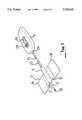
- FIG. 1is an isometric view of an infusion set according to the embodiment
- FIG. 2is an upper plan view of the housing of the embodiment
- FIG. 3is a sectional plan view of the housing according to the embodiment.
- FIG. 4is a sectional side elevation of the housing according to the embodiment.
- FIG. 5is a sectional plan view of the base and needle according to the embodiment.
- FIG. 6is a sectional side elevation of the base and needle according to the embodiment.
- FIG. 7is a sectional end elevation of the base and needle according to the embodiment.
- the infusion setcomprises a base 11, a needle 12, a flexible delivery tube 13 received within a flexible duct 23 and a housing 14.
- the base 11comprises a central tubular member 15 with a pair of lateral wing members 16 mounted thereto in diametrically opposed relation.
- the junction between the wing members 16 and the tubular portion 15are provided with a reduced thickness portion to provide a hinged connection 17 between the wings 16 and the tubular portion 15.
- the wings 16occupy the position as shown at which they extend to opposite sides of the tubular portion 15. When in that position they can be fixed to the arm or body of patient by use of suitable tape.
- the wings 16are hinged to a position (not shown) at which they are substantially adjacent and parallel to each other whereby they can be grasped between a thumb and a finger of the user to enable insertion.
- the needle 12is hollow and has one end 18 which is free and formed to a sharp point, while the other end 19 (see FIG. 6) is connected to one end 20 of the flexible delivery tube 13, whereby the interior of the hollow needle 12 is in open communication with the interior of the flexible delivery tube 13.
- the needle 12is slidably supported within the tubular member 15.
- the flexible delivery tube 13is received within the body of the housing 14 such that it enters the interior of the housing 14 at the proximate end of the housing 14 most adjacent the base 11 and is fixed at its other end 21 to the remote end of the housing 14 which is most remote from the base 11.
- the flexible delivery tubeis substantially inextensible. This may be effected by choice of the appropriate material or associating it with a fine wire bonded or fixed to the tube and fixed at one end to the tubular portion 13 and at the other end to the housing 14.
- the remote end of the housing 14is provided with a socket 22 which is shaped to sealingly receive the "LUER" fitting of a conventional syringe or receptacle used in relation to such infusion set and the other end 21 of the flexible delivery tube is fixed to the socket 22.
- the socketmay be configured to sealingly receive any other conventional fitting which may be able to be used.
- Such a fittingmay comprise a port or similar plug which can be pierced by a syringe or like means to sealingly deliver an agent to the delivery tube 13.
- the base 15is supported from the proximate end of the housing 14 by a flexible tubular duct 23 which is concentrically received over the flexible delivery tube 13 and is fixed at one end to the base 15 and at the other end to a tubular boss 24 provided at the proximate end of the housing.
- the flexible tubular duct 23may take any suitable form and need not be sealed. If desired it may incorporate or comprise a closely wound wire coil.
- the interior of the housing 14is provided with a pair of parallel guides 25 spaced to each side of the central axis between the proximate and remote end of the housing 14 and the wall of the upper face of the housing is formed with a longitudinal slot 26 which is located intermediate of the ribs 25.
- the ribssupport between themselves the engagement means which takes the form of a slider 27 which is slidably received between the ribs 25 for longitudinal movement within the housing 14 and which is associated with a control knob or handle 28 which is received within the slot 26 whereby the knob may be manipulated to cause slidable movement of the slider 27 within the housing 14.
- the slider 27is provided with a circular boss 29 which is associated with a concentric part circular arcuate rib 30 at the side of the boss remote from the proximate end of the housing 14 to define channel shaped space between the boss 29 and the arcuate rib 30 which is able to slidably receive the flexible delivery tube 13.
- the housingis further provided with a set of guide ribs 31 adjacent one exterior face of one of the longitudinal ribs 25.
- the guide ribsserve to define a convoluted pathway which is an extension of that defined between the boss 29 and the arcuate rib 30 on the slider 27.
- the portion of the flexible delivery tube 13 which is accommodated within the housing 14is received in the convoluted pathway defined between the boss 29 and arcuate rib 30 on the slider 27 and the guide ribs 31 provided in the housing.
- the pathwayis such that when the slider 27 is at its first position adjacent the proximate end of the housing 14 the pathway defined for the flexible tubing is arcuate whereby no kinks are induced in the flexible delivery tubing 13.
- the engagement between the slider 27 and the flexible tubing 13is such that on the slider 27 being moved longitudinally within the housing away from the proximate end thereof to its second position adjacent the remote end, a portion of flexible delivery tubing 13 accommodated within the duct 23 is drawn into the interior of the housing 14 which consequently causes the movement of the needle 12 into the tubular portion 15 of the base 11.
- the flexible delivery tube 13When the slider is at its second position most adjacent the remote end of the housing 14 the flexible delivery tube 13 has been sufficiently drawn into the body of the housing 14 to enable full retraction of the needle 12 into the tubular portion 15 and such that the free end 18 of the needle is unexposed.
- the flexible nature of the flexile delivery tube 13is such that on the slider 27 being moved from its second position most adjacent the remote end of the housing 14 to its first position most adjacent the proximate end of the housing 14 the portion of the flexible tubing within the housing 14 is not caused to re-enter the delivery duct 23 but will be caused to flex.
- the mounting of the needle 12 within the tubular portion 15is such that the needle is incapable of relative rotational movement within the tubular portion 15.
- thisis effected by forming the inner portion of the needle 12 with a series of convolutions which are substantially coplanar.
- the passageway in the tubular portion 15is formed at its end adjacent the housing with an expanded portion of oval cross section which is shaped to be able to receive the convoluted portion of the needle 12.
- the interengagement of the convolutions 32 within the expanded portion 33 of the passageway within the tubular portion 15serves to prevent relative rotation of the needle 12 with respect to the base 11.
- a detentsuch as a dimple 34 in the interior of the expanded portion 33 of the passageway in the tubular portion 15, engages a convolution when the needle 12 is in the extended position.
- the dimple 34provides sufficient resistance for the needle to be inserted into the body of a patient but such resistance can be overcome by the retractable movement of the slider 27.
- the slider 27may be associated with a locking means which will ensure locking engagement between the slider 27 and the body of the housing 14 on the slider 27 being moved to its retracted position.
- the housing 14may be associated with suitable stops or detent means (not shown) which will provide a tactile indication to the user on movement of the control knob 28 to indicate that the knob has been moved to either of its end positions.
- the basemay be formed such that on manipulation of the wings 16 the passage accommodating the needle is changed in cross-sectional configuration whereby when the wings are in their natural unstressed state the needle is held in position and when the wings are folded in a particular manner the needle is able to move in the passage.
- the needleis also retained in position when the wings have been folded to a position enabling the base to be held by an operator by the folded wings and the needle inserted into the body of the patient.
- the means for retracting the needleneed not have the form as described in relation to the embodiment but may comprise any means of causing retraction of the flexible delivery tube into the body of the housing 14 to effect retraction of the needle 12.
- the engagement meansmay comprise a capstan or a like element which is rotatably supported on or in the housing and which is able to wind the flexible delivery tube into the housing. If desired, the capstan is only rotatable on the housing in one direction in order to enable a retractable movement of the needle only.
- the movement of the engaging means to the retracted positionmay cause a destructive bending or "kinking" of the delivery tube to render the infusion set incapable of further use.
- the arrangement of the slider with respect to the baseis such that in the event of inadvertent movement of the slider from the retracted position to the extended position the delivery tube folds up or "kinks" rather than causing movement of the needle to the extended position.
- the needleis unconvoluted and is provided with a hub member which is slidably received in the tubular member.
- the hubis associated with a first detent to retain the needle in the extended position during use from which it can be released with appropriate force being applied to the delivery tube.
- the hubmay be associated with a second detent or similar engagement means which engages and retains the hub and needle in the retracted position.
- the first detentmay comprise a protrusion in the passage towards the outer end which is positioned and shaped to be engaged by the free end of the needle when the needle is moved to the retracted position.
- the arrangementis such that on the needle being moved to the retracted position the free end moves past the protrusion and if an attempt is made to move the needle to the extended position the free end engages the protrusion to prevent further movement of the needle out of the passage.
Landscapes
- Health & Medical Sciences (AREA)
- Life Sciences & Earth Sciences (AREA)
- Engineering & Computer Science (AREA)
- Hematology (AREA)
- General Health & Medical Sciences (AREA)
- Anesthesiology (AREA)
- Biomedical Technology (AREA)
- Heart & Thoracic Surgery (AREA)
- Veterinary Medicine (AREA)
- Animal Behavior & Ethology (AREA)
- Public Health (AREA)
- Pulmonology (AREA)
- Biophysics (AREA)
- Environmental & Geological Engineering (AREA)
- Vascular Medicine (AREA)
- Infusion, Injection, And Reservoir Apparatuses (AREA)
- Acyclic And Carbocyclic Compounds In Medicinal Compositions (AREA)
- Percussion Or Vibration Massage (AREA)
- Making Paper Articles (AREA)
Abstract
Description
THIS INVENTION relates to an infusion set.
Throughout the specification she term "infusion set" shall be taken as comprising a base adapted to be capable of being manipulated by a user to effect insertion or removal of the infusion set, a hollow needle having one pointed free end and the other end supported from the base and a flexible delivery tube connected at one end to the other end of the needle, the other end of the flexible delivery tube being adapted to be connected to a receptacle or delivery means.
Infusion sets of the type described above are associated with a very high incidence of accidental needle stick injury. One reason for such is because in use, after the user has removed the line from the vein of a patient the needle is usually held such that it is suspended from the flexible delivery tubing and is therefore able to move in a unpredictable manner due to the flexible resilient nature of the flexible delivery tubing. Also the needle can be difficult to control when suspended from the flexible delivery tubing when being carried to a safe "sharps" disposal container and then can be difficult to insert in to the "sharps" container without the risk of puncturing the hands or arms of the user. There is also significant danger to any persons in the vicinity of the user when the used infusion set is being carried. Furthermore, such infusion sets carry a high risk of transmission of infection such as HIV, Hepatitis and the like ailments due to the substantial quantity of blood remaining within the infusion set.
It is an object of this invention to provide an infusion set which on completion of its use can be rendered safe.
In one form the invention resides in an infusion set where a portion of the flexible delivery tube is supported at a position spaced from its one end from a housing and where a flexible duct is concentrically provided over the flexible tubing between the base and the housing to enable slidable movement of the flexible tubing within the duct, said needle being longitudinally slidable in the base, said housing having an engagement means movable on the housing and in engagement with the flexible tubing to cause longitudinal movement of the needle in the base between an extended position and retracted position on movement of the engagement means.
According to a preferred feature of the invention, a delivery tube is substantially inextendable.
According to a further preferred feature of the invention, the needle is substantially incapable of rotation about its central axis with respect of the base. This can be achieved in one embodiment by forming the portion of the needle accommodated within the base when in the extended position to be asymmetric about its central axis and a passage formed in the base of a complementary cross-sectional configuration. One form of asymmetry comprises forming the needle to be convoluted. Alternatively, the needle may be supported within the base by a hub which is slidably received in the base and if desired the hub may be configured such that it is incapable of rotation within the passage. This latter function can be achieved by forming the hub to be non circular and the passage of complementary configuration.
According to a preferred feature of the invention, the needle when in the retracted position is engaged with the base to prevent movement from the retracted position to the extended position. In addition, the needle is preferably engagable with the base when at the extended position to prevent movement from the extended position until after a predetermined force has been applied to the needle by the delivery tube. The retention of the needle in the extended position and the retracted position may be provided by a first detent means and a second detent means respectively in the base which is engagable by the needle and/or the hub supporting the needle when at the extended or retracted position respectively.
According to a further preferred feature of the invention, the engagement means is incapable of a movement with respect to the housing which would enable longitudinal movement of the needle from the retracted position to the extended position. In addition, the accommodation of the delivery tube within the housing is such as to prevent movement of the delivery tube from the housing into the flexible duct. In addition, the engagement means may take the form of a slider slidably supported on the housing or alternatively a capstan-like element rotatably supported on the housing.
The invention will be more fully understood in the light of the following description of one specific embodiment. The description is made with reference to the accompanying drawings of which;
FIG. 1 is an isometric view of an infusion set according to the embodiment;
FIG. 2 is an upper plan view of the housing of the embodiment;
FIG. 3 is a sectional plan view of the housing according to the embodiment;
FIG. 4 is a sectional side elevation of the housing according to the embodiment;
FIG. 5 is a sectional plan view of the base and needle according to the embodiment;
FIG. 6 is a sectional side elevation of the base and needle according to the embodiment; and
FIG. 7 is a sectional end elevation of the base and needle according to the embodiment.
The infusion set according to the embodiment comprises abase 11, aneedle 12, aflexible delivery tube 13 received within aflexible duct 23 and ahousing 14.
Thebase 11 comprises a centraltubular member 15 with a pair oflateral wing members 16 mounted thereto in diametrically opposed relation. The junction between thewing members 16 and thetubular portion 15 are provided with a reduced thickness portion to provide ahinged connection 17 between thewings 16 and thetubular portion 15. In use, thewings 16 occupy the position as shown at which they extend to opposite sides of thetubular portion 15. When in that position they can be fixed to the arm or body of patient by use of suitable tape. When it becomes necessary to insert the infusion set, thewings 16 are hinged to a position (not shown) at which they are substantially adjacent and parallel to each other whereby they can be grasped between a thumb and a finger of the user to enable insertion.
Theneedle 12 is hollow and has oneend 18 which is free and formed to a sharp point, while the other end 19 (see FIG. 6) is connected to oneend 20 of theflexible delivery tube 13, whereby the interior of thehollow needle 12 is in open communication with the interior of theflexible delivery tube 13. Theneedle 12 is slidably supported within thetubular member 15. Theflexible delivery tube 13 is received within the body of thehousing 14 such that it enters the interior of thehousing 14 at the proximate end of thehousing 14 most adjacent thebase 11 and is fixed at itsother end 21 to the remote end of thehousing 14 which is most remote from thebase 11. The flexible delivery tube is substantially inextensible. This may be effected by choice of the appropriate material or associating it with a fine wire bonded or fixed to the tube and fixed at one end to thetubular portion 13 and at the other end to thehousing 14.
The remote end of thehousing 14 is provided with asocket 22 which is shaped to sealingly receive the "LUER" fitting of a conventional syringe or receptacle used in relation to such infusion set and theother end 21 of the flexible delivery tube is fixed to thesocket 22. Alternatively, the socket may be configured to sealingly receive any other conventional fitting which may be able to be used. Such a fitting may comprise a port or similar plug which can be pierced by a syringe or like means to sealingly deliver an agent to thedelivery tube 13.
Thebase 15 is supported from the proximate end of thehousing 14 by a flexibletubular duct 23 which is concentrically received over theflexible delivery tube 13 and is fixed at one end to thebase 15 and at the other end to atubular boss 24 provided at the proximate end of the housing. The flexibletubular duct 23 may take any suitable form and need not be sealed. If desired it may incorporate or comprise a closely wound wire coil.
The interior of thehousing 14 is provided with a pair ofparallel guides 25 spaced to each side of the central axis between the proximate and remote end of thehousing 14 and the wall of the upper face of the housing is formed with alongitudinal slot 26 which is located intermediate of theribs 25. The ribs support between themselves the engagement means which takes the form of aslider 27 which is slidably received between theribs 25 for longitudinal movement within thehousing 14 and which is associated with a control knob orhandle 28 which is received within theslot 26 whereby the knob may be manipulated to cause slidable movement of theslider 27 within thehousing 14.
Theslider 27 is provided with acircular boss 29 which is associated with a concentric part circulararcuate rib 30 at the side of the boss remote from the proximate end of thehousing 14 to define channel shaped space between theboss 29 and thearcuate rib 30 which is able to slidably receive theflexible delivery tube 13.
The housing is further provided with a set ofguide ribs 31 adjacent one exterior face of one of thelongitudinal ribs 25. The guide ribs serve to define a convoluted pathway which is an extension of that defined between theboss 29 and thearcuate rib 30 on theslider 27.
The portion of theflexible delivery tube 13 which is accommodated within thehousing 14 is received in the convoluted pathway defined between theboss 29 andarcuate rib 30 on theslider 27 and theguide ribs 31 provided in the housing. The pathway is such that when theslider 27 is at its first position adjacent the proximate end of thehousing 14 the pathway defined for the flexible tubing is arcuate whereby no kinks are induced in theflexible delivery tubing 13.
The engagement between theslider 27 and theflexible tubing 13 is such that on theslider 27 being moved longitudinally within the housing away from the proximate end thereof to its second position adjacent the remote end, a portion offlexible delivery tubing 13 accommodated within theduct 23 is drawn into the interior of thehousing 14 which consequently causes the movement of theneedle 12 into thetubular portion 15 of thebase 11. When the slider is at its second position most adjacent the remote end of thehousing 14 theflexible delivery tube 13 has been sufficiently drawn into the body of thehousing 14 to enable full retraction of theneedle 12 into thetubular portion 15 and such that thefree end 18 of the needle is unexposed. The flexible nature of theflexile delivery tube 13 is such that on theslider 27 being moved from its second position most adjacent the remote end of thehousing 14 to its first position most adjacent the proximate end of thehousing 14 the portion of the flexible tubing within thehousing 14 is not caused to re-enter thedelivery duct 23 but will be caused to flex.
The mounting of theneedle 12 within thetubular portion 15 is such that the needle is incapable of relative rotational movement within thetubular portion 15. In the case of the embodiment this is effected by forming the inner portion of theneedle 12 with a series of convolutions which are substantially coplanar. The passageway in thetubular portion 15 is formed at its end adjacent the housing with an expanded portion of oval cross section which is shaped to be able to receive the convoluted portion of theneedle 12. The interengagement of theconvolutions 32 within the expandedportion 33 of the passageway within thetubular portion 15 serves to prevent relative rotation of theneedle 12 with respect to thebase 11. Furthermore, on retraction of theneedle 12 into thetubular portion 15 of thebase 11 as a result of theflexible delivery tube 13 being drawn into thehousing 14, the convolutions are drawn into theduct 23 and become frictionally engaged with the inner wall of theduct 23. Such frictional engagement serves to resist any tendency that the flexible delivery tube may have to re-enter theduct 23 from thehousing 14 on movement of theslider 27 from its second position to its first position.
In order to retain theneedle 12 in the extended position a detent such as a dimple 34 in the interior of the expandedportion 33 of the passageway in thetubular portion 15, engages a convolution when theneedle 12 is in the extended position. Thedimple 34 provides sufficient resistance for the needle to be inserted into the body of a patient but such resistance can be overcome by the retractable movement of theslider 27.
If desired theslider 27 may be associated with a locking means which will ensure locking engagement between theslider 27 and the body of thehousing 14 on theslider 27 being moved to its retracted position. Furthermore, thehousing 14 may be associated with suitable stops or detent means (not shown) which will provide a tactile indication to the user on movement of thecontrol knob 28 to indicate that the knob has been moved to either of its end positions.
In another embodiment the base may be formed such that on manipulation of thewings 16 the passage accommodating the needle is changed in cross-sectional configuration whereby when the wings are in their natural unstressed state the needle is held in position and when the wings are folded in a particular manner the needle is able to move in the passage. In such an arrangement the needle is also retained in position when the wings have been folded to a position enabling the base to be held by an operator by the folded wings and the needle inserted into the body of the patient.
The means for retracting the needle need not have the form as described in relation to the embodiment but may comprise any means of causing retraction of the flexible delivery tube into the body of thehousing 14 to effect retraction of theneedle 12.
In an alternative embodiment the engagement means may comprise a capstan or a like element which is rotatably supported on or in the housing and which is able to wind the flexible delivery tube into the housing. If desired, the capstan is only rotatable on the housing in one direction in order to enable a retractable movement of the needle only.
In addition, in both embodiments the movement of the engaging means to the retracted position may cause a destructive bending or "kinking" of the delivery tube to render the infusion set incapable of further use. In the case of the embodiment described above in relation to the drawings the arrangement of the slider with respect to the base is such that in the event of inadvertent movement of the slider from the retracted position to the extended position the delivery tube folds up or "kinks" rather than causing movement of the needle to the extended position.
Furthermore the configuration applied to the needle to ensure that it is not capable of rotation within the base may taken any desirable form.
In a further embodiment the needle is unconvoluted and is provided with a hub member which is slidably received in the tubular member. The hub is associated with a first detent to retain the needle in the extended position during use from which it can be released with appropriate force being applied to the delivery tube. The hub may be associated with a second detent or similar engagement means which engages and retains the hub and needle in the retracted position.
In another embodiment the first detent may comprise a protrusion in the passage towards the outer end which is positioned and shaped to be engaged by the free end of the needle when the needle is moved to the retracted position. The arrangement is such that on the needle being moved to the retracted position the free end moves past the protrusion and if an attempt is made to move the needle to the extended position the free end engages the protrusion to prevent further movement of the needle out of the passage.
It should be appreciated that the scope of the invention should not be limited to the particular scope of the above embodiment.
THE CLAIMS defining the invention are as follows;
Claims (22)
1. An infusion set comprising:
a portion of a flexible delivery tube which is supported at a position spaced from one end of the tube from a housing;
a flexible duct which is concentrically provided over the flexible delivery tube between a base and the housing to enable slidable movement of the flexible delivery tube within the duct; and
needle being received in the one end of the flexible delivery tube, the needle further being longitudinally slidable in the base, said housing having an engagement means movable on the housing for engaging the flexible delivery tube to cause longitudinal movement of the needle in the base between an extended position and a retracted position on movement of the engagement means.
2. An infusion set as claimed in claim 1 wherein the delivery tube is not extendible.
3. An infusion set as claimed in claim 1 wherein the needle is not rotatable about a central axis of the needle with respect to the base.
4. An infusion set as claimed in claim 1 wherein said needle is engaged with the base when moved from the extended position to the retracted position to prevent movement to the extended position from the retracted position.
5. An infusion set as claimed in claim 4 wherein the needle is engaged with the base to prevent movement from the extended position until after a predetermined force has been applied to the needle by the delivery tube.
6. An infusion set as claimed in claim 5 wherein the base is provided with a first detent means which is engagable by the needle when in the extended position to prevent said movement from the extended position.
7. An infusion set as claimed in claim 4 wherein the base is provided with a second detent means which is engaged by the needle when in the retracted position to prevent said movement from the retracted position.
8. An infusion set as claimed in claim 7 wherein at least a portion of the needle accommodated within the base when in the extended position is asymmetric about a central axis of the needle and is received in a passage formed in the base of complementary cross-sectional configuration.
9. An infusion set as claimed in claim 7 wherein a portion of the needle accommodated within the base is supported by a hub member slidably receivable in a passage formed in the base.
10. An infusion set as claimed in claim 9 wherein the hub is engaged with the second detent means.
11. An infusion set as claimed in claim 8 wherein the portion of the needle is convoluted.
12. An infusion set as claimed in claim 1 wherein the engagement means comprises a slider slidably supported from the housing whereby slidable movement of a slider causes said longitudinal movement of the needle.
13. An infusion set as claimed in claim 12 wherein said engagement means comprises a capstan-like element rotatably supported in the housing whereby rotation of a capstan-like element causes said longitudinal movement of the needle.
14. An infusion set as claimed in claim 1 wherein the engagement means in its movement on the housing is not able to effect longitudinal movement of the needle from the retracted position to the extended position.
15. An infusion set as claimed in claim 1 wherein accommodation of the delivery tube within the housing is such as to prevent movement of the delivery tube from the housing into the flexible duct.
16. An infusion set as claimed in claim 2 wherein the needle is not rotatable about a central axis of the needle with respect to the base.
17. An infusion set as claimed in claim 2 wherein said needle is engaged with the base when moved from the extended position to the retracted position to prevent movement to the extended position from the retracted position.
18. An infusion set as claimed in claim 3 wherein said needle is engaged with the base when moved from the extended position to the retracted position to prevent movement to the extended position from the retracted position.
19. An infusion set as claimed in claim 1 wherein the needle is engaged with the base to prevent movement from the extended position until after a predetermined force has been applied to the needle by the delivery tube.
20. An infusion set as claimed in claim 2 wherein the needle is engaged with the base to prevent movement from the extended position until after a predetermined force has been applied to the needle by the delivery tube.
21. An infusion set as claimed in claim 5 wherein the base is provided with a second detent means which is engaged by the needle when in the retracted position to prevent said movement from the retracted position.
22. An infusion set as claimed in claim 6 wherein the base is provided with a second detent means which is engaged by the needle when in the retracted position to prevent said movement from the retracted position.
Applications Claiming Priority (3)
| Application Number | Priority Date | Filing Date | Title |
|---|---|---|---|
| AUPM1468 | 1993-09-27 | ||
| AUPM146893 | 1993-09-27 | ||
| PCT/AU1994/000579WO1995009019A1 (en) | 1993-09-27 | 1994-09-23 | An infusion set |
Publications (1)
| Publication Number | Publication Date |
|---|---|
| US5762632Atrue US5762632A (en) | 1998-06-09 |
Family
ID=3777233
Family Applications (1)
| Application Number | Title | Priority Date | Filing Date |
|---|---|---|---|
| US08/617,772Expired - Fee RelatedUS5762632A (en) | 1993-09-27 | 1994-09-23 | Infusion set |
Country Status (15)
| Country | Link |
|---|---|
| US (1) | US5762632A (en) |
| EP (1) | EP0724461B1 (en) |
| JP (1) | JP3604692B2 (en) |
| KR (1) | KR100281508B1 (en) |
| AT (1) | ATE258449T1 (en) |
| AU (1) | AU677718B2 (en) |
| CA (1) | CA2172720C (en) |
| DE (2) | DE69433521T2 (en) |
| DK (1) | DK0724461T3 (en) |
| ES (1) | ES2215165T3 (en) |
| MY (1) | MY113938A (en) |
| PT (1) | PT724461E (en) |
| SG (1) | SG78238A1 (en) |
| WO (1) | WO1995009019A1 (en) |
| ZA (1) | ZA947521B (en) |
Cited By (29)
| Publication number | Priority date | Publication date | Assignee | Title |
|---|---|---|---|---|
| US6056718A (en)* | 1998-03-04 | 2000-05-02 | Minimed Inc. | Medication infusion set |
| WO2002094352A3 (en)* | 2001-05-18 | 2003-05-08 | Deka Products Lp | Infusion set for a fluid pump |
| US20030130618A1 (en)* | 2002-01-04 | 2003-07-10 | Gray Larry B. | Loading mechanism for infusion pump |
| US20050165384A1 (en)* | 2002-02-18 | 2005-07-28 | Danfoss A/S | Device for administering of medication in gluid form |
| US20060276750A1 (en)* | 2003-04-04 | 2006-12-07 | Jms Co. Ltd. | Medical needle device having with shield wings shield |
| US20080262434A1 (en)* | 2007-04-20 | 2008-10-23 | Vaillancourt Michael J | Huber needle with safety sheath |
| US7776016B1 (en) | 2004-02-26 | 2010-08-17 | C. R. Bard, Inc. | Huber needle safety enclosure |
| US7976504B1 (en)* | 2008-04-30 | 2011-07-12 | Abbott Cardiovascular Systems Inc. | Needle catheter with axially elongating and contracting needle |
| US8016789B2 (en) | 2008-10-10 | 2011-09-13 | Deka Products Limited Partnership | Pump assembly with a removable cover assembly |
| US8034026B2 (en) | 2001-05-18 | 2011-10-11 | Deka Products Limited Partnership | Infusion pump assembly |
| US8066672B2 (en) | 2008-10-10 | 2011-11-29 | Deka Products Limited Partnership | Infusion pump assembly with a backup power supply |
| US8223028B2 (en) | 2008-10-10 | 2012-07-17 | Deka Products Limited Partnership | Occlusion detection system and method |
| US8262616B2 (en) | 2008-10-10 | 2012-09-11 | Deka Products Limited Partnership | Infusion pump assembly |
| US8267892B2 (en) | 2008-10-10 | 2012-09-18 | Deka Products Limited Partnership | Multi-language / multi-processor infusion pump assembly |
| US8663538B2 (en) | 2009-02-12 | 2014-03-04 | Picolife Technologies, Llc | Method of making a membrane for use with a flow control system for a micropump |
| US8708376B2 (en) | 2008-10-10 | 2014-04-29 | Deka Products Limited Partnership | Medium connector |
| US8728029B2 (en) | 2001-12-17 | 2014-05-20 | Bard Access Systems, Inc. | Safety needle with collapsible sheath |
| US8771229B2 (en) | 2011-12-01 | 2014-07-08 | Picolife Technologies, Llc | Cartridge system for delivery of medicament |
| US8790307B2 (en) | 2011-12-01 | 2014-07-29 | Picolife Technologies, Llc | Drug delivery device and methods therefor |
| US9180245B2 (en) | 2008-10-10 | 2015-11-10 | Deka Products Limited Partnership | System and method for administering an infusible fluid |
| US9211378B2 (en) | 2010-10-22 | 2015-12-15 | Cequr Sa | Methods and systems for dosing a medicament |
| US9248234B2 (en) | 2010-09-10 | 2016-02-02 | C. R. Bard, Inc. | Systems for isolation of a needle-based infusion set |
| US9883834B2 (en) | 2012-04-16 | 2018-02-06 | Farid Amirouche | Medication delivery device with multi-reservoir cartridge system and related methods of use |
| US10130759B2 (en) | 2012-03-09 | 2018-11-20 | Picolife Technologies, Llc | Multi-ported drug delivery device having multi-reservoir cartridge system |
| US10245420B2 (en) | 2012-06-26 | 2019-04-02 | PicoLife Technologies | Medicament distribution systems and related methods of use |
| US10525234B2 (en) | 2010-09-10 | 2020-01-07 | C. R. Bard, Inc. | Antimicrobial/haemostatic interface pad for placement between percutaneously placed medical device and patient skin |
| US10729846B2 (en) | 2010-09-10 | 2020-08-04 | C. R. Bard, Inc. | Self-sealing pad for a needle-based infusion set |
| US12186531B2 (en) | 2008-10-10 | 2025-01-07 | Deka Products Limited Partnership | Infusion pump assembly |
| US12370327B2 (en) | 2008-10-10 | 2025-07-29 | Deka Products Limited Partnership | Infusion pump methods, systems and apparatus |
Families Citing this family (1)
| Publication number | Priority date | Publication date | Assignee | Title |
|---|---|---|---|---|
| WO2013136887A1 (en)* | 2012-03-15 | 2013-09-19 | テルモ株式会社 | Butterfly needle |
Citations (10)
| Publication number | Priority date | Publication date | Assignee | Title |
|---|---|---|---|---|
| DE2109608A1 (en)* | 1970-02-27 | 1971-10-14 | Frawley Enterprises, Inc., Culver City, Calif. (V.StA.) | Instrument for inserting a catheter |
| US4676783A (en)* | 1985-09-03 | 1987-06-30 | The University Of Virginia Alumni Patents Foundation | Retractable safety needle |
| US5067946A (en)* | 1990-04-10 | 1991-11-26 | Semen Zhadanov | Injury resistant needle device |
| US5108376A (en)* | 1990-11-14 | 1992-04-28 | Safetyject | Retractable intravenous needle assembly |
| US5152749A (en)* | 1991-06-28 | 1992-10-06 | American Medical Systems, Inc. | Instrument placement apparatus |
| US5192275A (en)* | 1991-09-18 | 1993-03-09 | Becton, Dickinson And Company | IV infusion or blood collection guard assembly |
| AU1489692A (en)* | 1992-04-14 | 1993-10-28 | International Safetyject Industries, Inc. | Retractable intravenous needle assembly |
| AU5477594A (en)* | 1993-02-03 | 1994-08-11 | Graham Cameron Dr. Grant | Intravenous infusion set |
| US5380293A (en)* | 1993-02-03 | 1995-01-10 | Grant; Graham C. | Intravenous infusion set |
| US5395347A (en)* | 1990-11-08 | 1995-03-07 | Mbo Laboratories, Inc. | Safe blood collection system |
Family Cites Families (4)
| Publication number | Priority date | Publication date | Assignee | Title |
|---|---|---|---|---|
| US3572334A (en)* | 1968-11-27 | 1971-03-23 | Johnson & Johnson | Intravenous catheter placement unit |
| US4781692A (en)* | 1985-09-03 | 1988-11-01 | The University Of Virginia Alumni Patents Foundation | Retractable safety needles |
| US5195974A (en)* | 1987-10-30 | 1993-03-23 | Menlo Care, Inc. | Needle protector for a catheter assembly |
| IT227968Y1 (en)* | 1992-11-17 | 1998-01-21 | Moris Baroni | NEEDLE FOR INTRAVENOUS AND EXTRACTABLE, SELF-GLOBAL WITHDRAWALS TO AVOID STITCHES AND CONTACTS TO PEOPLE AND ENVIRONMENTS AFTER USE |
- 1994
- 1994-09-23DEDE69433521Tpatent/DE69433521T2/ennot_activeExpired - Fee Related
- 1994-09-23KRKR1019960701571Apatent/KR100281508B1/ennot_activeExpired - Fee Related
- 1994-09-23EPEP94928706Apatent/EP0724461B1/ennot_activeExpired - Lifetime
- 1994-09-23USUS08/617,772patent/US5762632A/ennot_activeExpired - Fee Related
- 1994-09-23CACA002172720Apatent/CA2172720C/ennot_activeExpired - Fee Related
- 1994-09-23WOPCT/AU1994/000579patent/WO1995009019A1/enactiveIP Right Grant
- 1994-09-23DKDK94928706Tpatent/DK0724461T3/enactive
- 1994-09-23AUAU78028/94Apatent/AU677718B2/ennot_activeCeased
- 1994-09-23JPJP51000395Apatent/JP3604692B2/ennot_activeExpired - Fee Related
- 1994-09-23PTPT94928706Tpatent/PT724461E/enunknown
- 1994-09-23ESES94928706Tpatent/ES2215165T3/ennot_activeExpired - Lifetime
- 1994-09-23SGSG1996000792Apatent/SG78238A1/enunknown
- 1994-09-23ATAT94928706Tpatent/ATE258449T1/ennot_activeIP Right Cessation
- 1994-09-23DEDE0724461Tpatent/DE724461T1/enactivePending
- 1994-09-24MYMYPI94002542Apatent/MY113938A/enunknown
- 1994-09-27ZAZA947521Apatent/ZA947521B/enunknown
Patent Citations (10)
| Publication number | Priority date | Publication date | Assignee | Title |
|---|---|---|---|---|
| DE2109608A1 (en)* | 1970-02-27 | 1971-10-14 | Frawley Enterprises, Inc., Culver City, Calif. (V.StA.) | Instrument for inserting a catheter |
| US4676783A (en)* | 1985-09-03 | 1987-06-30 | The University Of Virginia Alumni Patents Foundation | Retractable safety needle |
| US5067946A (en)* | 1990-04-10 | 1991-11-26 | Semen Zhadanov | Injury resistant needle device |
| US5395347A (en)* | 1990-11-08 | 1995-03-07 | Mbo Laboratories, Inc. | Safe blood collection system |
| US5108376A (en)* | 1990-11-14 | 1992-04-28 | Safetyject | Retractable intravenous needle assembly |
| US5152749A (en)* | 1991-06-28 | 1992-10-06 | American Medical Systems, Inc. | Instrument placement apparatus |
| US5192275A (en)* | 1991-09-18 | 1993-03-09 | Becton, Dickinson And Company | IV infusion or blood collection guard assembly |
| AU1489692A (en)* | 1992-04-14 | 1993-10-28 | International Safetyject Industries, Inc. | Retractable intravenous needle assembly |
| AU5477594A (en)* | 1993-02-03 | 1994-08-11 | Graham Cameron Dr. Grant | Intravenous infusion set |
| US5380293A (en)* | 1993-02-03 | 1995-01-10 | Grant; Graham C. | Intravenous infusion set |
Non-Patent Citations (6)
| Title |
|---|
| Copy of International Publication No. WO 88/07387 dated 6 Oct. 1988 entitled "Retractable Safety Needle". |
| Copy of International Publication No. WO 88/07387 dated 6 Oct. 1988 entitled Retractable Safety Needle .* |
| Copy of International Publication No. WO 92/08502 dated 29 May 1992 entitled "Catheter Assembly Having Safety Means". |
| Copy of International Publication No. WO 92/08502 dated 29 May 1992 entitled Catheter Assembly Having Safety Means .* |
| Copy of International Publication No. WO 94/11050 dated 16 May 1994 entitled "Catheter Introducer Assembly Including Needle Shield". |
| Copy of International Publication No. WO 94/11050 dated 16 May 1994 entitled Catheter Introducer Assembly Including Needle Shield .* |
Cited By (46)
| Publication number | Priority date | Publication date | Assignee | Title |
|---|---|---|---|---|
| US6520938B1 (en) | 1998-03-04 | 2003-02-18 | Medtronic Minimed, Inc. | Medication infusion set |
| US6056718A (en)* | 1998-03-04 | 2000-05-02 | Minimed Inc. | Medication infusion set |
| US8034026B2 (en) | 2001-05-18 | 2011-10-11 | Deka Products Limited Partnership | Infusion pump assembly |
| WO2002094352A3 (en)* | 2001-05-18 | 2003-05-08 | Deka Products Lp | Infusion set for a fluid pump |
| US9173996B2 (en) | 2001-05-18 | 2015-11-03 | Deka Products Limited Partnership | Infusion set for a fluid pump |
| US8728029B2 (en) | 2001-12-17 | 2014-05-20 | Bard Access Systems, Inc. | Safety needle with collapsible sheath |
| US20030130618A1 (en)* | 2002-01-04 | 2003-07-10 | Gray Larry B. | Loading mechanism for infusion pump |
| US7306578B2 (en) | 2002-01-04 | 2007-12-11 | Deka Products Limited Partnership | Loading mechanism for infusion pump |
| US20090054867A1 (en)* | 2002-02-18 | 2009-02-26 | Peter Gravesen | Device for Administering of Medication in Fluid Form |
| US7517335B2 (en) | 2002-02-18 | 2009-04-14 | Cequr Aps | Device for administering of medication in fluid form |
| US8945064B2 (en) | 2002-02-18 | 2015-02-03 | Cequr Sa | Device for administering of medication in fluid form |
| US20050165384A1 (en)* | 2002-02-18 | 2005-07-28 | Danfoss A/S | Device for administering of medication in gluid form |
| US20060276750A1 (en)* | 2003-04-04 | 2006-12-07 | Jms Co. Ltd. | Medical needle device having with shield wings shield |
| US7776016B1 (en) | 2004-02-26 | 2010-08-17 | C. R. Bard, Inc. | Huber needle safety enclosure |
| US20100312183A1 (en)* | 2004-02-26 | 2010-12-09 | C. R. Bard, Inc. | Huber needle safety enclosure |
| US8852154B2 (en) | 2004-02-26 | 2014-10-07 | C. R. Bard, Inc. | Huber needle safety enclosure |
| US8574197B2 (en) | 2004-02-26 | 2013-11-05 | C. R. Bard, Inc. | Huber needle safety enclosure |
| US8152768B2 (en) | 2004-02-26 | 2012-04-10 | C. R. Bard, Inc. | Huber needle safety enclosure |
| US20080262434A1 (en)* | 2007-04-20 | 2008-10-23 | Vaillancourt Michael J | Huber needle with safety sheath |
| US8597253B2 (en) | 2007-04-20 | 2013-12-03 | Bard Access Systems | Huber needle with safety sheath |
| US9713673B2 (en) | 2007-04-20 | 2017-07-25 | Bard Access Systems, Inc. | Huber needle with safety sheath |
| US7976504B1 (en)* | 2008-04-30 | 2011-07-12 | Abbott Cardiovascular Systems Inc. | Needle catheter with axially elongating and contracting needle |
| US8267892B2 (en) | 2008-10-10 | 2012-09-18 | Deka Products Limited Partnership | Multi-language / multi-processor infusion pump assembly |
| US8262616B2 (en) | 2008-10-10 | 2012-09-11 | Deka Products Limited Partnership | Infusion pump assembly |
| US8223028B2 (en) | 2008-10-10 | 2012-07-17 | Deka Products Limited Partnership | Occlusion detection system and method |
| US8708376B2 (en) | 2008-10-10 | 2014-04-29 | Deka Products Limited Partnership | Medium connector |
| US8066672B2 (en) | 2008-10-10 | 2011-11-29 | Deka Products Limited Partnership | Infusion pump assembly with a backup power supply |
| US12370327B2 (en) | 2008-10-10 | 2025-07-29 | Deka Products Limited Partnership | Infusion pump methods, systems and apparatus |
| US12186531B2 (en) | 2008-10-10 | 2025-01-07 | Deka Products Limited Partnership | Infusion pump assembly |
| US8016789B2 (en) | 2008-10-10 | 2011-09-13 | Deka Products Limited Partnership | Pump assembly with a removable cover assembly |
| US9180245B2 (en) | 2008-10-10 | 2015-11-10 | Deka Products Limited Partnership | System and method for administering an infusible fluid |
| US8663538B2 (en) | 2009-02-12 | 2014-03-04 | Picolife Technologies, Llc | Method of making a membrane for use with a flow control system for a micropump |
| US8807169B2 (en) | 2009-02-12 | 2014-08-19 | Picolife Technologies, Llc | Flow control system for a micropump |
| US10525234B2 (en) | 2010-09-10 | 2020-01-07 | C. R. Bard, Inc. | Antimicrobial/haemostatic interface pad for placement between percutaneously placed medical device and patient skin |
| US9248234B2 (en) | 2010-09-10 | 2016-02-02 | C. R. Bard, Inc. | Systems for isolation of a needle-based infusion set |
| US10143799B2 (en) | 2010-09-10 | 2018-12-04 | C. R. Bard, Inc. | Systems for isolation of a needle-based infusion set |
| US10729846B2 (en) | 2010-09-10 | 2020-08-04 | C. R. Bard, Inc. | Self-sealing pad for a needle-based infusion set |
| US10806900B2 (en) | 2010-09-10 | 2020-10-20 | C. R. Bard. Inc. | Insertion device with interface pad and methods of making |
| US9211378B2 (en) | 2010-10-22 | 2015-12-15 | Cequr Sa | Methods and systems for dosing a medicament |
| US9993592B2 (en) | 2011-12-01 | 2018-06-12 | Picolife Technologies, Llc | Cartridge system for delivery of medicament |
| US10213549B2 (en) | 2011-12-01 | 2019-02-26 | Picolife Technologies, Llc | Drug delivery device and methods therefor |
| US8790307B2 (en) | 2011-12-01 | 2014-07-29 | Picolife Technologies, Llc | Drug delivery device and methods therefor |
| US8771229B2 (en) | 2011-12-01 | 2014-07-08 | Picolife Technologies, Llc | Cartridge system for delivery of medicament |
| US10130759B2 (en) | 2012-03-09 | 2018-11-20 | Picolife Technologies, Llc | Multi-ported drug delivery device having multi-reservoir cartridge system |
| US9883834B2 (en) | 2012-04-16 | 2018-02-06 | Farid Amirouche | Medication delivery device with multi-reservoir cartridge system and related methods of use |
| US10245420B2 (en) | 2012-06-26 | 2019-04-02 | PicoLife Technologies | Medicament distribution systems and related methods of use |
Also Published As
| Publication number | Publication date |
|---|---|
| ES2215165T3 (en) | 2004-10-01 |
| DE69433521D1 (en) | 2004-03-04 |
| CA2172720A1 (en) | 1995-04-06 |
| DE724461T1 (en) | 1997-02-13 |
| KR100281508B1 (en) | 2001-02-15 |
| WO1995009019A1 (en) | 1995-04-06 |
| DE69433521T2 (en) | 2004-11-18 |
| PT724461E (en) | 2004-06-30 |
| ZA947521B (en) | 1995-10-09 |
| AU677718B2 (en) | 1997-05-01 |
| EP0724461A1 (en) | 1996-08-07 |
| ATE258449T1 (en) | 2004-02-15 |
| JP3604692B2 (en) | 2004-12-22 |
| AU7802894A (en) | 1995-04-18 |
| EP0724461B1 (en) | 2004-01-28 |
| SG78238A1 (en) | 2001-02-20 |
| JPH09502899A (en) | 1997-03-25 |
| CA2172720C (en) | 2005-02-22 |
| MY113938A (en) | 2002-06-29 |
| DK0724461T3 (en) | 2004-06-07 |
| EP0724461A4 (en) | 1999-06-16 |
Similar Documents
| Publication | Publication Date | Title |
|---|---|---|
| US5762632A (en) | Infusion set | |
| EP1448251B1 (en) | Universal passive protector for an iv catheter | |
| US6832992B2 (en) | Passive safety device for needle of blood collection set | |
| US6682510B2 (en) | Passive safety device | |
| US9878130B2 (en) | Passively shielding needle device | |
| US7608057B2 (en) | Protective device for an injection needle | |
| JP3610304B2 (en) | Winged I.V. Device | |
| US8376994B2 (en) | Protective device for an injection needle | |
| EP0436646B1 (en) | Guarded winged needle assembly | |
| JP2781750B2 (en) | Safety exterior members | |
| US20040171995A1 (en) | Passive safety device for needle of IV infusion or blood collection set | |
| AU2002340363A1 (en) | Universal passive protector for an IV catheter | |
| EP0576302A1 (en) | Catheter with extensible, two-piece needle guard | |
| US7144388B2 (en) | Selectively passive shieldable medical needle device |
Legal Events
| Date | Code | Title | Description |
|---|---|---|---|
| AS | Assignment | Owner name:EASTLAND TECHNOLOGY AUSTRALIA PTY LTD, AUSTRALIA Free format text:ASSIGNMENT OF ASSIGNORS INTEREST;ASSIGNOR:WHISSON, MAXWELL EDMUND;REEL/FRAME:008026/0491 Effective date:19960315 | |
| AS | Assignment | Owner name:EASTLAND TECHNOLOGY AUSTRALIA PTY LTD., AUSTRALIA Free format text:ADDRRESS CHANGE;ASSIGNOR:EASTLAND TECHNOLOGY AUSTRALIA PTY LTD;REEL/FRAME:011533/0884 Effective date:20000927 | |
| FEPP | Fee payment procedure | Free format text:PETITION RELATED TO MAINTENANCE FEES FILED (ORIGINAL EVENT CODE: PMFP); ENTITY STATUS OF PATENT OWNER: SMALL ENTITY | |
| REMI | Maintenance fee reminder mailed | ||
| REIN | Reinstatement after maintenance fee payment confirmed | ||
| FPAY | Fee payment | Year of fee payment:4 | |
| SULP | Surcharge for late payment | ||
| FP | Lapsed due to failure to pay maintenance fee | Effective date:20020609 | |
| PRDP | Patent reinstated due to the acceptance of a late maintenance fee | Effective date:20020729 | |
| REMI | Maintenance fee reminder mailed | ||
| FPAY | Fee payment | Year of fee payment:8 | |
| SULP | Surcharge for late payment | Year of fee payment:7 | |
| REMI | Maintenance fee reminder mailed | ||
| LAPS | Lapse for failure to pay maintenance fees | ||
| STCH | Information on status: patent discontinuation | Free format text:PATENT EXPIRED DUE TO NONPAYMENT OF MAINTENANCE FEES UNDER 37 CFR 1.362 | |
| FP | Lapsed due to failure to pay maintenance fee | Effective date:20100609 |