US5762512A - Latchable battery pack for battery-operated electronic device having controlled power shutdown and turn on - Google Patents
Latchable battery pack for battery-operated electronic device having controlled power shutdown and turn onDownload PDFInfo
- Publication number
- US5762512A US5762512AUS08/541,238US54123895AUS5762512AUS 5762512 AUS5762512 AUS 5762512AUS 54123895 AUS54123895 AUS 54123895AUS 5762512 AUS5762512 AUS 5762512A
- Authority
- US
- United States
- Prior art keywords
- battery pack
- latching
- battery
- main housing
- cradle
- Prior art date
- Legal status (The legal status is an assumption and is not a legal conclusion. Google has not performed a legal analysis and makes no representation as to the accuracy of the status listed.)
- Expired - Lifetime
Links
- 238000013480data collectionMethods0.000claimsabstractdescription8
- 238000009434installationMethods0.000claimsdescription13
- 230000006835compressionEffects0.000claimsdescription7
- 238000007906compressionMethods0.000claimsdescription7
- 238000000605extractionMethods0.000claimsdescription6
- 230000000977initiatory effectEffects0.000claimsdescription2
- 230000007246mechanismEffects0.000abstractdescription23
- 230000000694effectsEffects0.000abstractdescription6
- 230000009471actionEffects0.000description13
- 230000014759maintenance of locationEffects0.000description12
- 238000000034methodMethods0.000description9
- 238000010276constructionMethods0.000description7
- 230000008569processEffects0.000description6
- 230000008901benefitEffects0.000description4
- 230000015572biosynthetic processEffects0.000description4
- 230000000994depressogenic effectEffects0.000description4
- 238000000638solvent extractionMethods0.000description4
- 230000000153supplemental effectEffects0.000description4
- 238000006073displacement reactionMethods0.000description3
- 230000006870functionEffects0.000description3
- 239000000463materialSubstances0.000description3
- 230000003287optical effectEffects0.000description3
- 238000013459approachMethods0.000description2
- 230000008859changeEffects0.000description2
- 238000013461designMethods0.000description2
- 238000010586diagramMethods0.000description2
- 238000003780insertionMethods0.000description2
- 230000037431insertionEffects0.000description2
- 230000000670limiting effectEffects0.000description2
- 230000008439repair processEffects0.000description2
- 239000002253acidSubstances0.000description1
- 230000006978adaptationEffects0.000description1
- 230000000712assemblyEffects0.000description1
- 238000000429assemblyMethods0.000description1
- 239000003990capacitorSubstances0.000description1
- 238000013479data entryMethods0.000description1
- 230000000779depleting effectEffects0.000description1
- 230000000881depressing effectEffects0.000description1
- 238000010494dissociation reactionMethods0.000description1
- 230000005593dissociationsEffects0.000description1
- 230000005489elastic deformationEffects0.000description1
- 238000004146energy storageMethods0.000description1
- 230000007274generation of a signal involved in cell-cell signalingEffects0.000description1
- 230000003993interactionEffects0.000description1
- 230000002452interceptive effectEffects0.000description1
- 238000004519manufacturing processMethods0.000description1
- 238000012986modificationMethods0.000description1
- 230000004048modificationEffects0.000description1
- 238000012545processingMethods0.000description1
- 230000004044responseEffects0.000description1
- 230000035939shockEffects0.000description1
- 238000012546transferMethods0.000description1
- 210000003462veinAnatomy0.000description1
Images


Classifications
- H—ELECTRICITY
- H01—ELECTRIC ELEMENTS
- H01M—PROCESSES OR MEANS, e.g. BATTERIES, FOR THE DIRECT CONVERSION OF CHEMICAL ENERGY INTO ELECTRICAL ENERGY
- H01M50/00—Constructional details or processes of manufacture of the non-active parts of electrochemical cells other than fuel cells, e.g. hybrid cells
- H01M50/20—Mountings; Secondary casings or frames; Racks, modules or packs; Suspension devices; Shock absorbers; Transport or carrying devices; Holders
- H01M50/204—Racks, modules or packs for multiple batteries or multiple cells
- H01M50/207—Racks, modules or packs for multiple batteries or multiple cells characterised by their shape
- H01M50/213—Racks, modules or packs for multiple batteries or multiple cells characterised by their shape adapted for cells having curved cross-section, e.g. round or elliptic
- Y—GENERAL TAGGING OF NEW TECHNOLOGICAL DEVELOPMENTS; GENERAL TAGGING OF CROSS-SECTIONAL TECHNOLOGIES SPANNING OVER SEVERAL SECTIONS OF THE IPC; TECHNICAL SUBJECTS COVERED BY FORMER USPC CROSS-REFERENCE ART COLLECTIONS [XRACs] AND DIGESTS
- Y02—TECHNOLOGIES OR APPLICATIONS FOR MITIGATION OR ADAPTATION AGAINST CLIMATE CHANGE
- Y02E—REDUCTION OF GREENHOUSE GAS [GHG] EMISSIONS, RELATED TO ENERGY GENERATION, TRANSMISSION OR DISTRIBUTION
- Y02E60/00—Enabling technologies; Technologies with a potential or indirect contribution to GHG emissions mitigation
- Y02E60/10—Energy storage using batteries
- Y—GENERAL TAGGING OF NEW TECHNOLOGICAL DEVELOPMENTS; GENERAL TAGGING OF CROSS-SECTIONAL TECHNOLOGIES SPANNING OVER SEVERAL SECTIONS OF THE IPC; TECHNICAL SUBJECTS COVERED BY FORMER USPC CROSS-REFERENCE ART COLLECTIONS [XRACs] AND DIGESTS
- Y10—TECHNICAL SUBJECTS COVERED BY FORMER USPC
- Y10S—TECHNICAL SUBJECTS COVERED BY FORMER USPC CROSS-REFERENCE ART COLLECTIONS [XRACs] AND DIGESTS
- Y10S439/00—Electrical connectors
- Y10S439/911—Safety, e.g. electrical disconnection required before opening housing
Definitions
- the present inventionrelates to battery-operated electronic devices in general, and more particularly to latchable battery packs and lockable storage cradles for use with such battery-operated electronic devices, and yet more particularly to controlling such devices to gracefully shut down prior to battery removal, and to gracefully turn on after battery installation.
- the useful life of the battery packthat is, the period of time during which it can power the device in a single session without depleting the amount of electric energy stored therein to a dangerous level, is limited, often to much less than the duration of the task to be performed.
- Still another object of the present inventionis to devise an assembly of the type here under consideration which includes a latching mechanism that assures reliable retention of the battery pack on the main housing of the assembly.
- a concomitant object of the present inventionis so to construct the latching mechanism of the above type as to be relatively simple in construction, inexpensive to manufacture, easy to use, and yet reliable in operation.
- Still another object of the present inventionis to design the aforementioned cradle in such a manner as to provide for locking of at least the device itself therein against unauthorized removal therefrom.
- a further object of the present inventionis to prevent data loss and to allow the aforementioned electronic device, especially when used as a data collection terminal, to gracefully shut down prior to the removal of the batteries or the battery pack therefrom for subsequent recharging.
- Yet a further object of the present inventionis to prevent power fluctuations and allow the aforementioned electronic device to gracefully turn on after installation of the batteries or the battery pack.
- a battery-powered, portable, electronic devicethat includes a main housing having a receiving recess; a battery pack separate from the main housing, including a portion received in the receiving recess of the main housing in an assembled position of the battery pack with respect to the main housing, and having a latching recess; and means for latching the battery pack in the assembled position.
- such latching meansincludes a support secured to the main housing at the receiving recess; a latching member mounted on the support for movement between an extended position in which the latching member extends into the latching recess of the battery pack then assuming its assembled position and thus latches the battery pack in place, and an unlatching position in which the latching member releases the battery pack for extraction of its aforementioned portion from the receiving recess of the main housing; and a locking member mounted on the support for movement between a locking position in which the locking member extends into the path of movement of the latching member toward the unlatching position, and a releasing position in which the locking member releases the latching member for such movement.
- a main advantage of the present invention as described so faris that, because of the presence of, and the need for properly manipulating, at least one of the latching and locking members of the latching mechanism constituting the latching means, it is made virtually impossible for the battery pack to become separated from the main housing in the absence of deliberate action on the part of the user of the battery-powered device.
- the supportincludes a pair of guiding portions for guiding the latching member while moving between its latching and unlatching positions. It is also advantageous when the support includes a pair of abutment portions, and the locking member includes a pair of corresponding engaging portions that engage the abutment portions of the support in the locking position of the locking member.
- a compression springthat urges the locking member towards the locking position thereof.
- Another advantageous feature of the present inventioninvolves the provision of an extension spring, one of the end portions of which is connected to the support, and the other to the latching member, to urge the latching member toward its unlatching position.
- An additional feature of the present inventioncan be found in the provision of the latching member with an engagement portion that overlaps the locking member in the releasing position of the latter as the latching member moves toward, or is in, its unlatching position to hold the locking member in its releasing position.
- the locking memberis provided with a ridge serving as an abutment for the engagement portion of the latching member in the unlatching position of the latter.
- such signal generating meansadvantageously includes a switch having a casing stationary relative to the support, and an actuating element movable relative to the casing and operatively connected to the battery pack, or in the event that the batteries are directly mounted in the device, to the battery door cover.
- the actuating elementextends into the path of movement of the locking member, or of the door, and is operative for initiating the generation of the control signal in dependence on its position relative to the casing.
- the present inventionis also directed to an electronic device assembly that includes said battery-powered, portable, electronic device which has a housing having a front portion and a back portion as considered from the vantage point of a user when the device is in use, and a cradle having a main compartment for receiving the back portion of the housing when the device is not being used as a portable device.
- said battery-powered, portable, electronic devicewhich has a housing having a front portion and a back portion as considered from the vantage point of a user when the device is in use, and a cradle having a main compartment for receiving the back portion of the housing when the device is not being used as a portable device.
- auxiliary compartment of the cradlefor recharging the battery pack when the latter is received in the auxiliary compartment.
- the assemblyfurther includes at least one additional battery pack interchangeable with the one battery pack and used in alternation therewith on the device so as to enable the respective other of them to be recharged.
- the cradlemay further have an additional compartment opening into the main compartment and configured to accommodate the battery pack mounted on the back portion of the housing while the latter is received in the main compartment.
- an electronic device assemblythat includes, besides the aforementioned housing and cradle, means for holding the housing in position relative to the cradle when the back portion of the housing is received in the main compartment of the cradle.
- the cradleis equipped with a supporting surface serving as an abutment for one end portion of the housing when the back portion of the housing is received in the compartment in a rest position relative to the cradle.
- the holding meansincludes, in accordance with one aspect of the present invention, a rim integral with the cradle and embracing at least a part of the one end portion of the housing when the housing is in its rest position relative to the cradle.
- the holding meansincludes, regardless of whether or not the cradle includes the aforementioned rim, a hookshaped projection on the cradle that passes through an opening provided in the back portion of the housing at its end portion that is situated remotely from the supporting surface, and engages behind a detaining wall that adjoins this opening when the housing assumes its rest position on the cradle.
- This hook-shaped projectionis elastically yieldable in a predetermined direction out of the path of movement of the detaining wall as the housing is being brought into and out of its rest position relative to the cradle.
- the cradleincludes a depressable portion that is elastically yieldable relative to the remainder of the cradle and carries the hook-shaped projection for joint movement with it to enable the hook-shaped projection to clear the detaining wall when the depressable portion of the cradle is depressed.
- the cradlefurther includes, in accordance with another aspect of the present invention, a substantially unyieldable portion arranged at a spacing from the hook-shaped projection as considered in the aforementioned predetermined direction.
- means for maintaining the hook-shaped projection in placeincluding a shuttle mounted on the cradle for movement into and out of a latching position in which a portion of the shuttle is interposed between the hook-shaped projection and the unyieldable portion of the cradle.
- means for urging the shuttle out of its latching position and toward its unlatching positionincludes a leaf spring mounted on the shuttle for joint movement with it and bracing itself against the cradle when displaced out of its unlatching position.
- the electronic device assemblyincludes means for bounding respective openings in the shuttle and the cradle that are substantially aligned with one another in the latching position of the shuttle to enable passage of a lock, especially a portion of a padlock, therethrough.
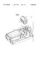
- FIG. 1is a partially exploded perspective view of an exemplary battery-powered device embodying the present invention, taken from the rear and from one side of the device;
- FIG. 2is a perspective view, on an enlarged scale and in a disassembled condition, of a latching mechanism of the present invention to be used for latching a battery pack in place with respect to a housing, taken from the other side of the device depicted in FIG. 1;
- FIGS. 3a and 3bare views corresponding to that of FIG. 2, but with the latching mechanism in its assembled condition and in its latching and releasing state, respectively;
- FIGS. 4a and 4bare still further enlarged side elevational views of the latching mechanism that correspond to those of FIGS. 3a and 3b, respectively, but taken from the same side as FIG. 1;
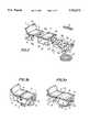
- FIG. 5is a perspective view taken from the right side of a retention cradle for temporarily accommodating the electronic device of the type depicted in FIG. 1 while not being used as a hand-held device;
- FIG. 6is a perspective exploded view taken from the left side of an upper portion of the retention cradle as considered in the position shown in FIG. 5 and revealing an additional feature of the present invention
- FIG. 7is partially sectioned view corresponding to FIG. 6 but showing the retention cradle in its assembled condition
- FIGS. 8a and 8bare sectional perspective views from below of a portion of the retention cradle, taken in the directions of the arrows 8--8 in FIG. 7;
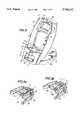
- FIG. 9is a front perspective view of a hand-held data collection terminal embodying the present invention, in accordance with another embodiment of a main housing thereof;
- FIG. 10is a rear perspective view of the terminal of FIG. 9;
- FIG. 11is a broken-away sectional view taken on line 11--11 of the terminal of FIG. 10;
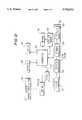
- FIG. 12is a schematic block diagram depicting the effect of battery removal/installation on the device.
- the reference numeral 10has been used therein to identify a battery-powered, portable, electronic device which incorporates the present invention, in its entirety.
- the device 10that is shown in the drawing, merely as an example of a device in which the present invention may be used to advantage, is constructed as, and has a configuration of, a hand-held data collection terminal having a built-in, electro-optical scanner of the type described in more detail in a copending and commonly owned U.S. patent application Ser. No. 08/489,729, filed Jun. 13, 1995, the disclosure of which is incorporated herein by reference to the extent required for better understanding of additional details of its structure and operation.
- the present inventioncan be used in a plethora of other battery-powered devices, whether intended to be hand-held or not, so long as each of them includes a main housing of any desirable shape.
- the aforementioned main housing denoted in FIG. 1, here by the reference numeral 11,is environmentally sealed and carries a so-called battery pack of the type indicated at 12 when the device 10 is in use or ready to be used.
- the battery pack 12is basically a separate cartridge, also environmentally sealed, and usually of a relatively rigid synthetic plastic material, which accommodates in its interior a battery proper (or a series of batteries) that may, but need not, be of the rechargeable type.
- the battery pack 12is to be mounted on the housing 11 for a relatively easy removal therefrom and assembly therewith, for instance for replacement of a nearly exhausted battery pack 12 by a fresh one, for placement of the battery pack 12 into a charging device (for example, see FIG.
- the main housing 11 of the device 10is provided with a receiving recess 13 that is dimensioned to receive, preferably in a substantially conforming fashion, a portion 14 of the battery pack 12.
- the battery pack 12will not be able to move relative to the main housing 11 in any other manner than that indicated in broken lines in FIG. 1, that is, in an extraction direction.
- the battery pack 12will have to be moved in the opposite, or insertion, direction, in order to introduce its portion 14 into the receiving recess 13 of the main housing 11.
- a pair of electrical contact arrangements 15 and 16is provided within the receiving recess 13, substantially at a bottom region thereof.
- contact arrangements 15 and 16serve for establishing electrical connection with respective corresponding terminals that are provided on the portion 14 of the battery pack 12 and that have not been shown in order not to unduly encumber the drawing because the provision of such cooperating contact and terminal arrangements is well known from other devices of this kind.
- FIG. 1also reveals that the battery pack 12 is provided, at its region just above the portion 14, with a latching recess 17.
- the latching recess 17serves to receive, preferably with only a minimum amount of leeway, a corresponding latching portion of a latching arrangement or mechanism 18 when the portion 14 of the battery pack 12 is properly seated within the receiving recess 13 of the main housing 11. It will become clear that this reception of the aforementioned latching portion of the latching mechanism 18 in the latching recess 17 of the battery pack 12 serves to retain the battery pack 12 in the receiving recess 13 of the main housing 11 against extraction in the aforementioned extraction direction.
- the latching mechanism 18includes, as its main components, a latching member 19 proper, a locking button 20, and a support 21.
- the support 21is mounted on the main housing 11 in any well known manner so as to stay in its position relative thereto, and the latching member 19 and the locking button 20 are supported on the support 21 for limited movement relative thereto in a manner yet to be described.
- the latching mechanism 18further includes an elastic compressed material, such as a coil-shaped compression spring 22 and an elastic tensioned material, such as a helical extension spring 23.
- an elastic compressed materialsuch as a coil-shaped compression spring 22
- an elastic tensioned materialsuch as a helical extension spring 23.
- the support 21is provided at its central region with a longitudinal channel 24 that serves to receive the helical extension spring 23 in the assembled condition of the latching mechanism 18, with one end of the spring 23 engaging a post 25 and/or behind another portion of the support 21 as illustrated especially in FIGS. 3a and 3b of the drawing.
- the other end of the helical extension spring 23engages the latching member 19 in a manner that is similar to that indicated above and hence is not illustrated.
- the helical extension spring 23serves to pull the latching member 19 with respect to the support 21 in the longitudinal direction of the channel 24 and in an unlatching direction when the latching mechanism 18 is in its assembled condition.
- the locking button 20prevents this motion in a manner also still to be described, unless deliberately moved out of the way.
- the support 21is provided, on the one hand, with a pair of rail-shaped abutment portions 26a and 26b that serve to limit the extent of "upward" movement of the locking button 20, that is its movement away from the main housing 11, this and the opposite direction being the only directions in which the locking button 20 is allowed to move because of the constraints imposed thereon by the main housing 11 and/or the support 21.
- This limiting actionis actually accomplished by the cooperation of the abutment portions 26a and 26b with corresponding projections 27a and 27b of the locking button 20, with these latter projections 27a and 27b engaging behind the abutment portions 26a and 26b in the "uppermost" position of the locking button 20.
- the coil-shaped compression spring 22which braces itself, in a known manner that has not been illustrated, against a corresponding portion of the main housing 11 in the assembled and operative condition of the latching mechanism 18, pushes the locking button 20 toward this upper or locking position.
- the support 21is further provided with a pair of guiding portions or rails 28a and 28b that are substantially conformingly received in corresponding channels of the latching member 19 in that respective portions 29a and 29b of the latching member 19 engage behind them, thus limiting the movement of the latching member 19 in the assembled condition of the latching mechanism 18 relative to the support 21, and thus with respect to the main housing 11 and to the battery pack 12, to the longitudinal direction of the channel 24 provided in the support 21 and thus to the direction in which the helical extension spring 23 is effective to affect and effectively limit the extent of such longitudinal movement.
- the locking button 20 and the latching member 19are provided with respective cooperating engagement portions 30 and 31, that the locking button 20 has a raised ridge 32, and that the latching member 19 has an upstanding actuating portion 33. It is this actuating portion 33 that enters and is received in the latching recess 17 in the latching state.
- a switch 34is provided, being mounted on the main housing 11 in any known manner so as to be able to cooperate with the locking button 20.
- FIG. 3a of the drawingthat shows the latching mechanism 18 in its latching state
- the latching member 19is in its latching or extended position
- the locking button 20is in its upper or locking position.
- the engagement portion 30 of the locking button 20is in the path of movement of the engagement portion 31 of the latching member 19, thus preventing such engagement portion 31 and thus the entire latching member 19 from conducting movement in the retraction direction thereof in which it is urged by the action of the aforementioned extension spring 23.
- the upstanding actuating portion 33 of the latching member 19is freed to conduct such movement against the action of the extension spring 23 thereon toward its unlatching position that is illustrated in FIG. 3b of the drawing.
- the engagement portion 31 of the latching member 19clears and rides on the corresponding engagement portion 30 of the locking button 20.
- the extent of such relative movement of the latching member 19is limited, if need be, by the presence of the ridge 32 on the locking button 20, in that the engagement portion 31 of the latching member 19 may abut against the ridge 32 under such circumstances.
- the engagement of the portions 30 and 31 with one anotherholds the locking button 20 in its depressed or “down” position, until the latching member 19 is deliberately moved into its latching position of FIG. 3a, using the actuating portion 33 of the latching member 19 for this purpose, if necessary.
- the effect of the locking button 20is to safely maintain the latching member 19 in its extended position in which it latches the battery pack 12 in position relative to the main housing 11, unless and until released by depression of the locking button 20, an action that cannot occur spontaneously at all, and can hardly be expected to happen in an accidental manner.
- FIGS. 4a and 4b of the drawingwhile also showing, with some additional degree of clarity, the cooperation of the latching member 19 and the locking button or member 20 with one another in the latching and unlatching conditions of the latching mechanism 18, also indicate the manner in which the latching mechanism cooperates with the aforementioned switch 34.
- the function of the switch 34is to detect the impending removal of the battery pack 12 from the main housing 11 in time to allow the electronic or other circuitry or arrangement contained in or on the device 10 to shut down "gracefully", that is, in a manner that will not result in any loss of information and/or otherwise interfere with the proper operation of the device 10 once powered up again.
- the switch 34includes, besides a casing 35 that is, as mentioned before, mounted on the main housing 11 in such a manner as to be stationary relative thereto, an actuation element 36 that is movable with respect to the casing 35 and that serves to close the switch proper in its extended position shown in FIG. 4a and open it in its depressed position of FIG. 4b.
- the actuation element 36bypasses the compression spring 22 at some dis tance therefrom, but extends into the path of movement of the locking button 20 from its locking position of FIG. 4a toward its releasing position of FIG. 4b.
- the depression of the locking button 20is what gets the whole unlatching process started, that is, it must be completed before the latching member 19 can even commence its movement from its latching to its unlatching position
- the depression of the actuation element 36 and the consequent opening of the switch properwhich take place during the course of downward movement of the locking button 20, of necessity precede the removal of the battery pack 12 by a certain amount of time which, while it may vary depending on the dexterity of the user and/or the speed with which he or she accomplishes the battery pack removal, is always sufficient to allow the aforementioned graceful shut down of the electronic circuitry and other equipment of the device 10.
- the force of the compression spring at disengagementis designed to be greater than the shock force that would be experienced even for a drop at a substantial height, thereby preventing accidental unlatching.
- the switch 34remains actuated until another willful action takes place, namely not only the cessation of the application of pressure on the locking button 20 but also the subsequent movement of the latching member 19 by a deliberate action on the part of the user into its latching position.
- Thiscan only happen because of deliberate action on the part of the user because the engagement portion 31 of the latching member 19 overlaps the corresponding engagement portion 30 of the locking member 20 holding the latter down, and continues to do so until the latching member 19 is displaced fully into its latching position. Since such displacement is resisted by the action of the extension spring 23, it is unlikely to happen in the absence of deliberate action of the user.
- control signal for beginning to power up the electronic and other electrical circuitry or componentscannot be generated until some time after the battery pack 12 has been installed and the electrical connection of its battery terminals with the contacts 15 and 16 has been safely established, thus avoiding any problems that could result from voltage spikes or fluctuations that may occur during the establishment of such electrical connections.
- the switch 34could be used to actually interrupt the supply of electric power to the various electrical or electronic components of the device 10 and to re-establish it later.
- the switchis closed in its position of FIG. 4a and open in its position of FIG. 4b inasmuch as it is the change in the level of the signal, rather than the value of such signal, that matters under these circumstances.
- shutoff or turn on signalmust "know” the significance of such change, i.e. it must be informed, by software or otherwise, that a first signal level (whether it be high or low) means that the locking button 20 is in or approaches its locking position while the other level signifies that the locking button 20 is approaching or is already in its releasing position.
- FIG. 5 of the drawingdepicts a retention cradle 40 that is constructed to safely and securely hold or accommodate the electronic device 10 illustrated in FIG. 1 of the drawing while such device 10 is not being used as a hand-held device, that is, while it is either not being used at all, or while it is being used as a stationary device.
- the retention cradle 40is provided with a receiving compartment 41 shaped to receive the handle portion or back side (that is, the side facing in the upward direction in FIG. 1) of the housing 11 of the device 10, advantageously in a substantially conforming fashion.
- the receiving compartment 41additionally includes a depression 42 shaped to receive the battery pack 12 so long as the latter is properly mounted on the main housing 11.
- the retention cradle 40further includes at least one supporting surface 44 at its bottom region, for the corresponding bottom region of the main housing 11 to rest upon when the device 10 is put down into the cradle.
- compartment 41opening upwardly, frontwardly, or to one side or the other, depending on the exigencies of the moment and/or the particular circumstances encountered at the location at which the cradle 40 is to be mounted, such as space availability and access, and/or the preferences or convenience of the user.
- the supporting surface 44which is shown to be provided on a ledge 45 (actually, a pair of them, with the other one being obscured, however) will not actually support the main housing 11 of the device 10 but rather serve merely as an abutment for delimiting the extent of insertion on the housing 11 into the compartment 41 as the device 10 is being deposited onto or into the cradle 40.
- the cradle 40is shown to include a base 46 by means of which it is mounted on a non-illustrated support.
- the base 46may be made and usually is large enough to prevent toppling over of the cradle 40 while empty and, coupled with a rearwardly reclining orientation of the cradle 40, even when the latter supports the device 10, and even when the base 46 merely rests on a horizontal (or only slightly inclined) support surface.
- the base 46is provided with a plurality of openings 47 (just one shown) through which screws, bolts or other fastening elements can be passed to connect the base 46 and thus the entire cradle 40 to the support.
- the cradle 40is also provided at its bottom region with a ridge or rim 48 that rises above the level of the supporting surface 44.
- the presence of the rim 48prevents introduction of the housing 11 into the compartment 41 by a simple front-to-back movement; rather, the housing 11 has to be introduced into the compartment 41 at a slightly higher elevation than that or the top of the rim 48 to clear the latter, and then let or caused to drop or descend until it abuts against the supporting surface 44.
- the rim 48prevents the bottom portion of the housing 11 from accidentally slipping out of the compartment 41 of the cradle 40, as desired in accordance with the present invention.
- FIG. 5 of the drawingalso shows that the cradle 40 further includes an auxiliary compartment 49 that is shaped to partially receive the battery pack 12 of the device 10 (or a supplemental one just like it).
- Contact arrangements 15' and 16'not unlike, or identical to, those indicated in FIG. 1 of the drawing at 15 and 16, are arranged at appropriate locations within the auxiliary compartment 49 to cooperate with the aforementioned terminals of the respective battery pack 12.
- the contact arrangements 15' and 16'are electrically connected not with the device 10 but with a source of electric power, such as a battery charging device or circuitry at least a part of which may be accommodated within the cradle 40.
- a slider or latching member 31'is mounted on the cradle 40 (actually, at least partly on the rim 48 thereof) for sliding in the up or down direction.
- the slider 31'When the slider 31' is in its uppermost position, it offers unrestricted access for the auxiliary compartment 49 for unimpeded introduction of the respective battery pack 12 into, or its removal from, the auxiliary compartment 49.
- its portion 33'extends into the latching recess 17 (see FIG. 1) of the respective battery pack 12, provided that the latter is properly received in the auxiliary compartment 49, and hence latches the battery pack 12 in its position in which its terminals are in electrical contact with the contact arrangements 15' and 16'.
- its engagement portion 31'may be corrugated, as shown.
- the slider 31'is advantageously positioned on the cradle 40 in such a manner as to be made either inaccessible and/or substantially immovable by the device 10 when the latter is supported on the cradle 40 in its proper rest position, that is, with the back or handgrip portion of the housing 11 being substantially conformingly received in the main compartment 41 of the cradle 40.
- the above-discussed recharging feature of the present inventioncan be used for recharging the battery or batteries of the very battery pack 12 that has been used to power the device 10 immediately prior to the commencement of the recharging operation, such as during extended periods of inactivity of the device (such as overnight), in that the battery pack 12 is dissociated from the main housing 11 in the manner described before and introduced into and latched in the auxiliary compartment 49 in the just-described manner.
- this recharging featureand the recharging or auxiliary compartment 49 in which it is performed for charging the supplemental battery pack mentioned before while the original one shown at 12 in FIG.
- the supplemental battery pack mounted in the auxiliary compartment 49is recharged at the same time as the original one, while mounted on the device and received in the depression 42.
- the rim 48retains the bottom portion of the housing 11 of the device in the retention compartment 41. This may be sufficient under some circumstances. However, in accordance with the present invention, it is further proposed to hold the affected portion of the housing 11 of the device 10 in the compartment 41 at its upper region as well.
- the housing 11is provided, as shown in FIG. 1 of the drawing, with an opening 50 that is separated from the recess 13 by a partitioning wall 51 and, on the other side, is adjoined by a web-shaped detaining wall 52.
- the cradle 40is provided, at a location that is appropriate for this purpose, with a hook-shaped projection or nose 53 that is configured and positioned in such a manner, and has, and/or the surrounding areas of the cradle 40 have, such inherent properties, as to resiliently yield out of the path of movement of the detaining wall 52 as the upper portion of the housing 11 is moved backwards in the retention compartment 41 of the cradle 40 while the bottom of the housing 11 is in contact with the supporting surface 44. This out-of-the-way yielding continues until the hook-shaped nose 53 fully enters the opening 50 and engages behind the detaining wall 52.
- This engagement of the nose 53 with the detaining wall 52is often all that is needed to safely retain the upper portion of the housing 11 in the compartment 41.
- all that is needed to remove the device 10 from the cradle 40 in this scenariois to cause the nose 53 to yield out of the path of movement of the detaining wall 52, either by deliberately depressing it or the surrounding areas of the cradle 40, or by applying to the device a force sufficient for the nose 52 to the deformed in such a manner as to enter the opening 50.
- the cradle 40includes a back part 40a and a front part 40b that are rigidly connected with one another in any well-known manner in an assembled condition of the cradle 40, as well as a nose-carrying member 60 that is equipped with the aforementioned nose 53 and is connected to the back part 40a of the cradle 40 in a cantilevered fashion by two screws 61a and 61b in the illustrated embodiment.
- the nose-carrying member 60includes a raised portion 62 that is shown to actually carry the nose 53, and is substantially fittingly received in a cutout 63 that is provided in the back part 40a of the cradle 40, but with freedom of movement into the compartment 41 and back to the extent permitted by the resiliency and/or the cantilevered mounting of the nose-carrying member 60.
- This in-and-out movementfacilitates the introduction of the nose 53 into the opening 50 and its engagement behind the detaining wall 52, as well as, and especially, the reverse of this process, i.e. the disengagement of the nose 53 from the detaining wall 52 and its withdrawal from the opening 50.
- at least the withdrawal processwould be impossible to accomplish without damaging the cradle 40 and/or the device 10 beyond repair in the absence of such yielding movement.
- this methodinvolves the use of a shuttle 70 that is supported in the cradle 40 in a manner yet to be described for movement between its locking and releasing positions.
- the shuttle 70is elongated and substantially strip-shaped, having respective first and second ends 71 and 72.
- the first end 71carries a leaf spring 73 that is so mounted on the shuttle 70 as to extend substantially transversely thereto and normal to its major surfaces, presenting a different portion or wing on each side of the shuttle 70.
- the other or second end portion 72is provided with a through aperture 74.
- a deformable motion-limiting formation 75is provided on the shuttle 70 intermediate its ends 71 and 72.
- FIG. 6also shows that the cradle 40 is provided at its backside with a protuberance 54 that is provided with a through hole 55.
- the first end 71 of the shuttle 70is interposed between the raised portion or button 62 and a substantially rigid and unyieldable internal portion 56 of the cradle 40, after the shuttle 70 has been pushed fully into its locking position by a force indicated at F 1 . Because of this interposition and the high resistance of the internal portion 56 to deformation or displacement, when the shuttle 70 is pushed fully in, the raised portion 62 cannot yield either when pressed upon by a force F 2 even if such force has a rather substantial magnitude.
- the main if not only purpose of the shuttle 70is to prevent unauthorized removal of the device 10 from the cradle 40.
- This very purposewould be defeated if anyone were able to move the shuttle 70 from its locking to its releasing position at will or, worse yet, if the shuttle 70 tended to return to its releasing position by itself, as is indeed the case in the illustrated embodiment of the present invention.
- the hole 55 in the protuberance 54 and the aperture 74 in the second end portion 72 of the shuttle 70come in. More particularly, in the locking position of the shuttle 70, the aperture 74 is at least substantially aligned with the hole 55, so that the U-shaped member of a small padlock can be passed through them.
- the freedom of movement of the shuttle 70is terminated once the U-shaped member of the padlock (or, for that matter, any other fitting object, such as a pencil or a pen), is passed through such aligned openings 74 and 55; however, the locking of the padlock assures that no person not having the key to the padlock or not privy to the numerical combination that opens the padlock, as the case may be, will be able to remove the interfering object (the U-shaped member of the padlock) from the aligned openings 74 and 55 and hence move the shuttle 70, or cause it to move, to its releasing position.
- FIGS. 8a and 8b of the drawingFurther details of the construction of the shuttle 70 and of the cooperating parts of the cradle 40, and especially of the nose-carrying member 60 thereof, are revealed in FIGS. 8a and 8b of the drawing. It may be observed there that in the releasing position of FIG. 8a the leaf spring 73 is substantially straight, i.e. relaxed, being situated next to a pair of detaining portions 58a and 58b provided stationarily within the cradle 40. On the other hand, as the shuttle 70 is moved, in response to the application of the force F 1 to its second end 72, toward its locking position illustrated in FIG.
- the two wings of the leaf spring 73first come into contact with the detaining portions 58a and 58b, respectively, if they were not in such contact to begin with, whereupon any further displacement of the shuttle 70 in the locking direction results in resilient or elastic deformation of the leaf spring 73.
- Thisis accompanied by energy storage in the spring 73, causing the latter to urge the shuttle 70 toward its releasing position and actually displace it into this position once the application of the force F 1 (or its substitute, such as that applied by the bracing action of the padlock) is terminated.
- FIGS. 8a and 8bthe motion-limiting formation 75 is deformed relative to its shape shown in FIG. 6.
- the reason for this deformationwhich may be attended to only after the shuttle 70 has been introduced into a corresponding channel of the cradle 40 and/or into its nose-carrying member 60 in its original condition, is to assure that the shuttle 70 cannot be withdrawn from or fall out of such channel once properly installed therein, in that this motionlimiting formation 75 in its thus deformed condition is unable to clear certain obstructions placed in its way that it had bypassed or would be able to bypass in its undeformed condition.
- a partitioning wall 76 in the interior of the cradle 40which has an open slot wide enough for the shuttle 70 itself to freely pass therethrough, but sufficiently narrow not to let the formation 75 to pass though it when it is in its deformed state.
- the aforementioned device 10is, in accordance with said co-pending application, preferably a data collection terminal having an on-board electro-optical scanner operative for reading coded indicia such as bar code symbols.
- a scannerincludes a light source, preferably a laser diode, for emitting a laser beam through an exit port or window to a symbol for reflection therefrom.
- Optical elements in the path of the laser beamare used to focus the laser beam to an optical spot having a generally circular or oval cross-section throughout a working distance exteriorly of the device.
- Light reflected from the symbolenters the window and is detected by a photodetector, preferably a photodiode, over a field of view.
- the laser beam and/or the field of viewis swept by a movable scanning element, typically a scan mirror in the path of the laser beam and/or the field of view.
- the detectorgenerates an analog electrical signal of variable intensity indicative of portions of the symbol that have different light reflective characteristics.
- the variable analog signalis converted into digital signals by a digitizer circuit.
- the widths of the digital signalscorresponds to the widths of the symbol portions, i.e., the bars and spaces thereof.
- These digital signalsare then decoded by a separate decoder or preferably by a microprocessor in accordance with an algorithm into data descriptive of the symbol being read. This data is stored in an on-board memory for subsequent downloading to a remote host computer for processing.
- a keyboard or analogous manual entry systemis provided on the terminal to enable manual data entry.
- a displayis also provided for displaying the data or other related information.
- a triggeris often used to enable a user to initiate the reading operation.
- the light source, optical elements, the photodetector and the scanning elementare mounted in a dome-shaped superstructure at the upper end of the main hosing.
- the display and keyboardare not visible in FIG. 1, and are situated at the front of the main housing.
- the trigger(and, in this case, two triggers) is situated at the back of the housing.
- the microprocessor, the memory and other circuitryare mounted within the main housing.
- the device 100includes a main housing 111, and a superstructure 102 in which the scan engine is mounted.
- a window 104permits exit of the outgoing light beam and the return of the light reflected from the bar code symbol to be read.
- the superstructure 102can be swiveled so that the window 104 faces in the illustrated direction (toward the right) or in the opposite direction (toward the left).
- a keyboard 106 and a display 108are provided on the front of the housing.
- a trigger 103is provided at the side of the housing.
- a set of batteries 105, 107is mounted in a receiving recess 113. These batteries supply the electrical power to enable all the electrical components within the device 100 to operate.
- a set of electrical contact arrangements 115, 116 within the recess 113is used to conduct the battery power to the electrical components.
- a door 112 hinged at hinge 117 to the housing 111is movable between a closed position (as illustrated) in which access to the recess 113 is blocked, and an open position (not illustrated) in which the batteries can be replaced.
- Door 112has a depending post 120 which cooperates, as described below, with an actuating portion 136 of an electrical switch 134 stationarily mounted with the housing 111.
- the post 120In the closed position, the post 120 depresses the actuating portion 136 and actually moves the latter toward the right in FIG. 11, thereby generating a control signal.
- the post 120releases the actuating portion and allows the latter to return to its original extended position in the path of movement of the post 120.
- This control signalis used to signal the device of the impending removal of the batteries and, as a result, to gracefully shut down the electrical components as described above, and is further used to signal the device of the re-installation of the batteries, again to gracefully power up the electrical components as described above.
- FIG. 12is a schematic block diagram generally depicting the interaction between battery removal/installation and the power shutdown/turn on features of the present invention.
- the keyboard 106 and the display 108are operatively connected to a microprocessor or controller 150.
- the scan engine 160includes the laser source 152, the detector 154, the scanner 156 and the digitizer 158, and is operatively connected to the controller 150.
- the trigger 103initiates the reading of the coded indicia, and is also operatively connected to the controller 150.
- the controller 150stores its data, typically the decoded signal indicative of the coded indicia, in a memory 162 for subsequent downloading.
- Block 164represents the removal of battery power to the device.
- the impending removal of the battery pack 12 from the recess 13is detected in advance by the movement in one direction of the actuating portion 36 of the switch 34.
- the impending removal of the batteries 105, 107is forewarned by the opening of the door 112 which, in turn, causes the actuating portion 136 of the switch 134 to be moved outwardly of its casing.
- the switch 34 or 134generates a control signal which is conducted to, and detected by, the controller 150 which, in turn, executes a routine to safely and gracefully shut down the electrical components.
- Block 164also schematically represents the installation of battery power to the device.
- the installation of the battery pack 12 within the recessis detected in advance by the movement of the actuating portion 36 of the switch 34 in the opposite direction to that described above for battery pack removal.
- the installation of the batteries 105, 107is forewarned by the closing of the door 112 which, in turn, causes the actuating portion 136 of the switch 134 to be moved inwardly of its casing.
- the switch 34 or 134generates a control signal having a state different from that generated during battery power removal. This different state control signal is conducted to, and detected by, the controller 150 which, in turn, executes another routine to safely and gracefully turn on the electrical components in a gradual manner to avoid voltage fluctuations.
Landscapes
- Chemical & Material Sciences (AREA)
- Chemical Kinetics & Catalysis (AREA)
- Electrochemistry (AREA)
- General Chemical & Material Sciences (AREA)
- Battery Mounting, Suspending (AREA)
Abstract
Description
Claims (16)
Priority Applications (2)
| Application Number | Priority Date | Filing Date | Title |
|---|---|---|---|
| US08/541,238US5762512A (en) | 1995-10-12 | 1995-10-12 | Latchable battery pack for battery-operated electronic device having controlled power shutdown and turn on |
| US09/036,464US6002236A (en) | 1995-10-12 | 1998-03-06 | Lockable storage cradle for battery-operated electronic device |
Applications Claiming Priority (1)
| Application Number | Priority Date | Filing Date | Title |
|---|---|---|---|
| US08/541,238US5762512A (en) | 1995-10-12 | 1995-10-12 | Latchable battery pack for battery-operated electronic device having controlled power shutdown and turn on |
Related Child Applications (1)
| Application Number | Title | Priority Date | Filing Date |
|---|---|---|---|
| US09/036,464DivisionUS6002236A (en) | 1995-10-12 | 1998-03-06 | Lockable storage cradle for battery-operated electronic device |
Publications (1)
| Publication Number | Publication Date |
|---|---|
| US5762512Atrue US5762512A (en) | 1998-06-09 |
Family
ID=24158751
Family Applications (2)
| Application Number | Title | Priority Date | Filing Date |
|---|---|---|---|
| US08/541,238Expired - LifetimeUS5762512A (en) | 1995-10-12 | 1995-10-12 | Latchable battery pack for battery-operated electronic device having controlled power shutdown and turn on |
| US09/036,464Expired - LifetimeUS6002236A (en) | 1995-10-12 | 1998-03-06 | Lockable storage cradle for battery-operated electronic device |
Family Applications After (1)
| Application Number | Title | Priority Date | Filing Date |
|---|---|---|---|
| US09/036,464Expired - LifetimeUS6002236A (en) | 1995-10-12 | 1998-03-06 | Lockable storage cradle for battery-operated electronic device |
Country Status (1)
| Country | Link |
|---|---|
| US (2) | US5762512A (en) |
Cited By (70)
| Publication number | Priority date | Publication date | Assignee | Title |
|---|---|---|---|---|
| US5868794A (en)* | 1997-04-08 | 1999-02-09 | Survivalink Corporation | AED and battery pack with anticipatory battery disengagement detection |
| US6002236A (en)* | 1995-10-12 | 1999-12-14 | Symbol Technologies, Inc. | Lockable storage cradle for battery-operated electronic device |
| US6014010A (en)* | 1998-04-22 | 2000-01-11 | Yao; Li-Ho | Charger compatible with different-sized rechargeable batteries of mobile telephones |
| USD420974S (en)* | 1999-01-06 | 2000-02-22 | Philip Morris Incorporated | Desktop charger |
| USD421418S (en)* | 1998-07-13 | 2000-03-07 | Hewlett-Packard Company | Battery cover for hand held apparatus such as an optical scanner |
| US6072250A (en)* | 1998-06-01 | 2000-06-06 | Motorola, Inc. | Battery pack having a hibernate circuit |
| USD433380S (en)* | 1999-11-05 | 2000-11-07 | Hewlett-Packard Company | Battery cover for hand held apparatus such as an optical scanner |
| US6421233B1 (en)* | 2000-06-12 | 2002-07-16 | High Tech Computer Corporation | Pocket personal computer with improved battery compartment enclosing structure |
| US20030006290A1 (en)* | 2001-05-02 | 2003-01-09 | Hand Held Products, Inc. | Optical reader comprising soft key including permanent graphic indicia |
| US20030124200A1 (en)* | 1999-06-22 | 2003-07-03 | Stone Kevin R. | Cartilage enhancing food supplements with sucralose and methods of preparing the same |
| US20030186119A1 (en)* | 2002-03-28 | 2003-10-02 | Omron Automotive Electronics Inc. | Methodology for making electrical contact from a button cell battery to a printed circuit board and a process for manufacturing the same |
| USD481008S1 (en) | 2002-12-23 | 2003-10-21 | Vq Orthocare | Battery pack housing for electrical stimulator |
| USD483016S1 (en) | 2002-11-15 | 2003-12-02 | Motorola, Inc. | Communication device accessory |
| US6656626B1 (en) | 1999-06-01 | 2003-12-02 | Porter-Cable Corporation | Cordless power tool battery release mechanism |
| US6658204B2 (en) | 2002-04-16 | 2003-12-02 | Aos Holding Company | Door insulator with safety plug |
| US6660427B1 (en)* | 2000-11-06 | 2003-12-09 | Motorola Inc. | Latch assembly for portable electronic device |
| US20040001997A1 (en)* | 2002-06-27 | 2004-01-01 | Vocollect, Inc. | Wearable terminal |
| US6727677B1 (en) | 2003-01-08 | 2004-04-27 | Moshe Bouskila | Adapter interface unique to each model mobile telephone with standardized charger |
| USD498302S1 (en) | 2003-11-12 | 2004-11-09 | Vq Orthocare | Electrical stimulator |
| US20050003266A1 (en)* | 2003-07-01 | 2005-01-06 | Thomas Wulff | Systems and methods for a controllable release of power supply in a mobile device |
| US20050095899A1 (en)* | 2002-06-27 | 2005-05-05 | Vocollect, Inc. | Voice-directed portable terminals for wireless communication systems |
| US20060091853A1 (en)* | 2002-04-25 | 2006-05-04 | Briggs Scott W | Battery disable/enable control circuitry of a portable computing device |
| USD521933S1 (en) | 2003-12-05 | 2006-05-30 | Visionquest Industries, Inc. | Electrode lead wire connector |
| US20060252469A1 (en)* | 2005-05-09 | 2006-11-09 | Roger Lu | Shut down mechanism for handheld device |
| US20070243457A1 (en)* | 2006-04-12 | 2007-10-18 | Andres Viduya | Electronic device with multiple battery contacts |
| USD558761S1 (en) | 2005-09-19 | 2008-01-01 | Vocollect, Inc. | Portable processing terminal |
| US20080007209A1 (en)* | 2006-06-21 | 2008-01-10 | Thomas Wulff | System and method for battery removal in a mobile device |
| USD567219S1 (en) | 2005-11-15 | 2008-04-22 | Vocollect, Inc. | Headset |
| USD567218S1 (en) | 2005-11-16 | 2008-04-22 | Vocollect, Inc. | Control panel for a headset |
| USRE40848E1 (en) | 1994-06-10 | 2009-07-14 | Pitzen James F | Combination rechargeable, detachable battery system and power tool |
| USD605629S1 (en) | 2008-09-29 | 2009-12-08 | Vocollect, Inc. | Headset |
| US20100026099A1 (en)* | 2006-12-08 | 2010-02-04 | Shinji Oguri | Electronic apparatus, charger, charging system, and charging method |
| US7773767B2 (en) | 2006-02-06 | 2010-08-10 | Vocollect, Inc. | Headset terminal with rear stability strap |
| USD626949S1 (en) | 2008-02-20 | 2010-11-09 | Vocollect Healthcare Systems, Inc. | Body-worn mobile device |
| US20100315036A1 (en)* | 2009-06-16 | 2010-12-16 | Sheng-Hsin Liao | Charger and combination of the charger and a socket panel |
| US7885419B2 (en) | 2006-02-06 | 2011-02-08 | Vocollect, Inc. | Headset terminal with speech functionality |
| USD643013S1 (en) | 2010-08-20 | 2011-08-09 | Vocollect Healthcare Systems, Inc. | Body-worn mobile device |
| USD643400S1 (en) | 2010-08-19 | 2011-08-16 | Vocollect Healthcare Systems, Inc. | Body-worn mobile device |
| US20120049784A1 (en)* | 2010-08-26 | 2012-03-01 | Symbol Technologies, Inc. | Method and apparatus for charging handheld data capture device with cradle |
| US8160287B2 (en) | 2009-05-22 | 2012-04-17 | Vocollect, Inc. | Headset with adjustable headband |
| US8386261B2 (en) | 2008-11-14 | 2013-02-26 | Vocollect Healthcare Systems, Inc. | Training/coaching system for a voice-enabled work environment |
| US8417185B2 (en) | 2005-12-16 | 2013-04-09 | Vocollect, Inc. | Wireless headset and method for robust voice data communication |
| US8438659B2 (en) | 2009-11-05 | 2013-05-07 | Vocollect, Inc. | Portable computing device and headset interface |
| US8659397B2 (en) | 2010-07-22 | 2014-02-25 | Vocollect, Inc. | Method and system for correctly identifying specific RFID tags |
| US20140140013A1 (en)* | 2012-11-19 | 2014-05-22 | Hon Hai Precision Industry Co., Ltd. | Electronic device with power supply control module |
| US20150380872A1 (en)* | 2014-06-29 | 2015-12-31 | William J. Warren | Electrical charging devices and assemblies |
| US9627802B2 (en) | 2014-06-29 | 2017-04-18 | William J. Warren | Electrical charging devices and assemblies |
| US20170150983A1 (en)* | 2013-01-16 | 2017-06-01 | Covidien Lp | Hand held electromechanical surgical system including battery compartment diagnostic display |
| US20170184394A1 (en)* | 2015-12-27 | 2017-06-29 | Faro Technologies, Inc. | 3-d measuring device with battery pack |
| US9883700B2 (en)* | 2014-08-21 | 2018-02-06 | Philip Morris Products S.A. | Aerosol-generating device and system |
| US20180076570A1 (en)* | 2015-03-23 | 2018-03-15 | Harting Electric Gmbh & Co. Kg | Modular plug connector |
| US9997882B1 (en) | 2017-02-27 | 2018-06-12 | William J. Warren | Electrical charging devices and assemblies |
| US10027149B2 (en) | 2014-06-29 | 2018-07-17 | William J. Warren | Electrical charging device chassis and cases |
| US10063088B2 (en) | 2014-06-29 | 2018-08-28 | William J. Warren | Computing device inductive charging cases and methods of use |
| US10153649B2 (en) | 2014-06-29 | 2018-12-11 | William J. Warren | Computing device charging cases and methods of use |
| US10177584B2 (en) | 2017-02-27 | 2019-01-08 | William J. Warren | Electrical charging devices and assemblies |
| US10355501B2 (en) | 2017-10-11 | 2019-07-16 | William J. Warren | Electrical charging devices with resilient actuation |
| US10370869B2 (en)* | 2015-12-06 | 2019-08-06 | Beijing Mobike Technology Co., Ltd. | Horseshoe-shaped lock |
| US10608449B2 (en) | 2017-02-27 | 2020-03-31 | William J. Warren | Electrical charging devices with translating stabilizers |
| US10608384B2 (en) | 2017-02-27 | 2020-03-31 | William J. Warren | Electrical charging devices with bar stabilizers and assemblies |
| USD886733S1 (en) | 2017-04-11 | 2020-06-09 | William J. Warren | Charger |
| US10944131B2 (en) | 2016-12-16 | 2021-03-09 | Milwaukee Electric Tool Corporation | Battery pack switch |
| US11179841B2 (en)* | 2016-12-16 | 2021-11-23 | Milwaukee Electric Tool Corporation | Battery pack interface |
| US11251508B2 (en) | 2017-03-24 | 2022-02-15 | Milwaukee Electric Tool Corporation | Terminal configuration for a battery pack |
| US11374528B2 (en) | 2017-06-30 | 2022-06-28 | Milwaukee Electric Tool Corporation | High power battery-powered system |
| US11641795B2 (en) | 2018-09-27 | 2023-05-09 | Nanjing Chervon Industry Co., Ltd. | Lawn mower |
| CN116134652A (en)* | 2020-09-14 | 2023-05-16 | 斑马技术公司 | removable battery pack |
| USD987691S1 (en) | 2018-09-27 | 2023-05-30 | Nanjing Chervon Industry Co., Ltd. | Mower blade assembly |
| USD995569S1 (en) | 2019-04-18 | 2023-08-15 | Nanjing Chervon Industry Co., Ltd. | Mower blade assembly |
| USD1096606S1 (en) | 2018-02-16 | 2025-10-07 | Milwaukee Electric Tool Corporation | Terminal block portion of a battery pack |
Families Citing this family (38)
| Publication number | Priority date | Publication date | Assignee | Title |
|---|---|---|---|---|
| US6380751B2 (en) | 1992-06-11 | 2002-04-30 | Cascade Microtech, Inc. | Wafer probe station having environment control enclosure |
| US5345170A (en) | 1992-06-11 | 1994-09-06 | Cascade Microtech, Inc. | Wafer probe station having integrated guarding, Kelvin connection and shielding systems |
| US5561377A (en) | 1995-04-14 | 1996-10-01 | Cascade Microtech, Inc. | System for evaluating probing networks |
| US5871272A (en) | 1997-01-28 | 1999-02-16 | Streamlight, Incorporated | Flashlight with rotatable lamp head |
| US6002263A (en) | 1997-06-06 | 1999-12-14 | Cascade Microtech, Inc. | Probe station having inner and outer shielding |
| US6130520A (en)* | 1998-03-13 | 2000-10-10 | Welch Allyn, Inc. | Diagnostic instrument system |
| US6265844B1 (en)* | 1998-07-02 | 2001-07-24 | Ericsson Inc. | Battery pack with photo means for enabling integral circuitry |
| WO2000079625A1 (en)* | 1999-06-18 | 2000-12-28 | Leupold & Stevens, Inc. | Replaceable battery module |
| US6445202B1 (en) | 1999-06-30 | 2002-09-03 | Cascade Microtech, Inc. | Probe station thermal chuck with shielding for capacitive current |
| SG90078A1 (en)* | 1999-11-15 | 2002-07-23 | Creative Tech Ltd | Docking interface for portable device |
| US6127802A (en)* | 1999-11-19 | 2000-10-03 | Motorola, Inc. | Charger with battery retention door |
| US6350040B1 (en)* | 2000-05-05 | 2002-02-26 | Pelican Products, Inc. | Flashlight charger and rechargeable battery |
| US6965226B2 (en) | 2000-09-05 | 2005-11-15 | Cascade Microtech, Inc. | Chuck for holding a device under test |
| US6914423B2 (en) | 2000-09-05 | 2005-07-05 | Cascade Microtech, Inc. | Probe station |
| US6633152B2 (en) | 2001-04-26 | 2003-10-14 | Streamlight, Inc. | Rechargeable flashlight and battery charger |
| USD466511S1 (en) | 2001-07-31 | 2002-12-03 | Symbol Technologies, Inc. | Cradle for a hand held portable electronic device |
| US6777964B2 (en) | 2002-01-25 | 2004-08-17 | Cascade Microtech, Inc. | Probe station |
| US6847219B1 (en) | 2002-11-08 | 2005-01-25 | Cascade Microtech, Inc. | Probe station with low noise characteristics |
| US7250779B2 (en) | 2002-11-25 | 2007-07-31 | Cascade Microtech, Inc. | Probe station with low inductance path |
| WO2004049834A1 (en)* | 2002-11-29 | 2004-06-17 | Unilever Plc | Beverage product with modified starch and nitrogen |
| US6861856B2 (en) | 2002-12-13 | 2005-03-01 | Cascade Microtech, Inc. | Guarded tub enclosure |
| US7215084B1 (en) | 2003-02-11 | 2007-05-08 | Streamlight, Inc. | Power control arrangement, as for a flashlight |
| US7221172B2 (en) | 2003-05-06 | 2007-05-22 | Cascade Microtech, Inc. | Switched suspended conductor and connection |
| US7492172B2 (en) | 2003-05-23 | 2009-02-17 | Cascade Microtech, Inc. | Chuck for holding a device under test |
| US20050012718A1 (en)* | 2003-07-17 | 2005-01-20 | Xing-Zhi Lin | Wireless pointing device with power-supplying module |
| US7250626B2 (en) | 2003-10-22 | 2007-07-31 | Cascade Microtech, Inc. | Probe testing structure |
| US7187188B2 (en) | 2003-12-24 | 2007-03-06 | Cascade Microtech, Inc. | Chuck with integrated wafer support |
| WO2005121824A2 (en) | 2004-06-07 | 2005-12-22 | Cascade Microtech, Inc. | Thermal optical chuck |
| US7330041B2 (en) | 2004-06-14 | 2008-02-12 | Cascade Microtech, Inc. | Localizing a temperature of a device for testing |
| US7656172B2 (en) | 2005-01-31 | 2010-02-02 | Cascade Microtech, Inc. | System for testing semiconductors |
| US7535247B2 (en) | 2005-01-31 | 2009-05-19 | Cascade Microtech, Inc. | Interface for testing semiconductors |
| US7556203B2 (en)* | 2005-06-27 | 2009-07-07 | Hand Held Products, Inc. | Method and system for linking a wireless hand held optical reader with a base unit or other wireless device |
| US7686216B2 (en) | 2006-06-13 | 2010-03-30 | Hand Held Products, Inc. | Method and apparatus for uniquely associating a bar code reading terminal to a cash register in a retail store network |
| WO2009137433A2 (en)* | 2008-05-09 | 2009-11-12 | Elnstruction Corporation | Charging and security station for multiple wireless tablets |
| TWI399881B (en)* | 2008-05-30 | 2013-06-21 | Fih Hong Kong Ltd | Locking device for battery |
| US8319503B2 (en) | 2008-11-24 | 2012-11-27 | Cascade Microtech, Inc. | Test apparatus for measuring a characteristic of a device under test |
| US8847774B1 (en)* | 2011-12-07 | 2014-09-30 | Jeffrey Bryan Gronneberg | Invisible barrier rechargeable battery assembly |
| TW201445278A (en)* | 2013-05-20 | 2014-12-01 | Hon Hai Prec Ind Co Ltd | Mobile power supply |
Citations (7)
| Publication number | Priority date | Publication date | Assignee | Title |
|---|---|---|---|---|
| US3917372A (en)* | 1974-10-03 | 1975-11-04 | Motorola Inc | Supporting and connecting structure for electric device |
| US4146682A (en)* | 1977-05-13 | 1979-03-27 | Olympus Optical Co., Ltd. | Battery case holding mechanism |
| US4371594A (en)* | 1980-10-03 | 1983-02-01 | Canon Kabushiki Kaisha | Battery accommodating device |
| US4880712A (en)* | 1989-03-08 | 1989-11-14 | Motorola, Inc. | Battery housing |
| US5187422A (en)* | 1991-07-31 | 1993-02-16 | Stryker Corporation | Charger for batteries of different type |
| US5220520A (en)* | 1990-01-31 | 1993-06-15 | Kabushiki Kaisha Toshiba | Compact portable electronic apparatus capable of storing data when a power supply is removed |
| US5310998A (en)* | 1989-10-31 | 1994-05-10 | Kabushiki Kaisha Toshiba | Method and system for placing a bus on hold during the insertion/extraction of an IC card into/from a computer |
Family Cites Families (6)
| Publication number | Priority date | Publication date | Assignee | Title |
|---|---|---|---|---|
| US2701332A (en)* | 1953-02-18 | 1955-02-01 | Yardney International Corp | Device for charging electric storage batteries |
| US5052943A (en)* | 1989-03-23 | 1991-10-01 | Norand Corporation | Recharging and data retrieval apparatus |
| JP2711784B2 (en)* | 1992-11-16 | 1998-02-10 | ユピテル工業株式会社 | Battery pack charger |
| JP3048784B2 (en)* | 1993-05-14 | 2000-06-05 | 三洋電機株式会社 | Chargers and electronic devices |
| US5327067A (en)* | 1993-06-02 | 1994-07-05 | Dell Usa, L.P. | Portable computer battery charging apparatus |
| US5762512A (en)* | 1995-10-12 | 1998-06-09 | Symbol Technologies, Inc. | Latchable battery pack for battery-operated electronic device having controlled power shutdown and turn on |
- 1995
- 1995-10-12USUS08/541,238patent/US5762512A/ennot_activeExpired - Lifetime
- 1998
- 1998-03-06USUS09/036,464patent/US6002236A/ennot_activeExpired - Lifetime
Patent Citations (7)
| Publication number | Priority date | Publication date | Assignee | Title |
|---|---|---|---|---|
| US3917372A (en)* | 1974-10-03 | 1975-11-04 | Motorola Inc | Supporting and connecting structure for electric device |
| US4146682A (en)* | 1977-05-13 | 1979-03-27 | Olympus Optical Co., Ltd. | Battery case holding mechanism |
| US4371594A (en)* | 1980-10-03 | 1983-02-01 | Canon Kabushiki Kaisha | Battery accommodating device |
| US4880712A (en)* | 1989-03-08 | 1989-11-14 | Motorola, Inc. | Battery housing |
| US5310998A (en)* | 1989-10-31 | 1994-05-10 | Kabushiki Kaisha Toshiba | Method and system for placing a bus on hold during the insertion/extraction of an IC card into/from a computer |
| US5220520A (en)* | 1990-01-31 | 1993-06-15 | Kabushiki Kaisha Toshiba | Compact portable electronic apparatus capable of storing data when a power supply is removed |
| US5187422A (en)* | 1991-07-31 | 1993-02-16 | Stryker Corporation | Charger for batteries of different type |
Cited By (119)
| Publication number | Priority date | Publication date | Assignee | Title |
|---|---|---|---|---|
| USRE40848E1 (en) | 1994-06-10 | 2009-07-14 | Pitzen James F | Combination rechargeable, detachable battery system and power tool |
| US6002236A (en)* | 1995-10-12 | 1999-12-14 | Symbol Technologies, Inc. | Lockable storage cradle for battery-operated electronic device |
| US5868794A (en)* | 1997-04-08 | 1999-02-09 | Survivalink Corporation | AED and battery pack with anticipatory battery disengagement detection |
| US6014010A (en)* | 1998-04-22 | 2000-01-11 | Yao; Li-Ho | Charger compatible with different-sized rechargeable batteries of mobile telephones |
| US6072250A (en)* | 1998-06-01 | 2000-06-06 | Motorola, Inc. | Battery pack having a hibernate circuit |
| USD421418S (en)* | 1998-07-13 | 2000-03-07 | Hewlett-Packard Company | Battery cover for hand held apparatus such as an optical scanner |
| USD420974S (en)* | 1999-01-06 | 2000-02-22 | Philip Morris Incorporated | Desktop charger |
| US7429430B2 (en) | 1999-06-01 | 2008-09-30 | Black & Decker Inc. | Cordless power tool battery release mechanism |
| US6656626B1 (en) | 1999-06-01 | 2003-12-02 | Porter-Cable Corporation | Cordless power tool battery release mechanism |
| US20040081883A1 (en)* | 1999-06-01 | 2004-04-29 | Tom Mooty | Cordless power tool battery release mechanism |
| US20030124200A1 (en)* | 1999-06-22 | 2003-07-03 | Stone Kevin R. | Cartilage enhancing food supplements with sucralose and methods of preparing the same |
| USD433380S (en)* | 1999-11-05 | 2000-11-07 | Hewlett-Packard Company | Battery cover for hand held apparatus such as an optical scanner |
| US6421233B1 (en)* | 2000-06-12 | 2002-07-16 | High Tech Computer Corporation | Pocket personal computer with improved battery compartment enclosing structure |
| US6660427B1 (en)* | 2000-11-06 | 2003-12-09 | Motorola Inc. | Latch assembly for portable electronic device |
| US20030006290A1 (en)* | 2001-05-02 | 2003-01-09 | Hand Held Products, Inc. | Optical reader comprising soft key including permanent graphic indicia |
| US6899273B2 (en) | 2001-05-02 | 2005-05-31 | Hand Held Products, Inc. | Optical reader comprising soft key including permanent graphic indicia |
| US20030186119A1 (en)* | 2002-03-28 | 2003-10-02 | Omron Automotive Electronics Inc. | Methodology for making electrical contact from a button cell battery to a printed circuit board and a process for manufacturing the same |
| US7175677B2 (en) | 2002-03-28 | 2007-02-13 | Omron Corporation | Methodology for making electrical contact from a button cell battery to a printed circuit board and a process for manufacturing the same |
| US6658204B2 (en) | 2002-04-16 | 2003-12-02 | Aos Holding Company | Door insulator with safety plug |
| US7429848B2 (en)* | 2002-04-25 | 2008-09-30 | Hewlett-Packard Development Company, L.P. | Battery disable/enable control circuitry of a portable computing device |
| US20060091853A1 (en)* | 2002-04-25 | 2006-05-04 | Briggs Scott W | Battery disable/enable control circuitry of a portable computing device |
| US8128422B2 (en) | 2002-06-27 | 2012-03-06 | Vocollect, Inc. | Voice-directed portable terminals for wireless communication systems |
| US20050095899A1 (en)* | 2002-06-27 | 2005-05-05 | Vocollect, Inc. | Voice-directed portable terminals for wireless communication systems |
| US20040001997A1 (en)* | 2002-06-27 | 2004-01-01 | Vocollect, Inc. | Wearable terminal |
| US20050272401A1 (en)* | 2002-06-27 | 2005-12-08 | Vocollect, Inc. | Environmentally-sealed portable terminal |
| US7052799B2 (en) | 2002-06-27 | 2006-05-30 | Vocollect, Inc. | Wearable terminal with a battery latch mechanism |
| USD483016S1 (en) | 2002-11-15 | 2003-12-02 | Motorola, Inc. | Communication device accessory |
| USD481008S1 (en) | 2002-12-23 | 2003-10-21 | Vq Orthocare | Battery pack housing for electrical stimulator |
| US6727677B1 (en) | 2003-01-08 | 2004-04-27 | Moshe Bouskila | Adapter interface unique to each model mobile telephone with standardized charger |
| US20070165480A1 (en)* | 2003-07-01 | 2007-07-19 | Symbol Technologies, Inc. | Systems and methods for a controllable release of power supply in a mobile device |
| US20050003266A1 (en)* | 2003-07-01 | 2005-01-06 | Thomas Wulff | Systems and methods for a controllable release of power supply in a mobile device |
| US7299373B2 (en) | 2003-07-01 | 2007-11-20 | Symbol Technologies, Inc. | Systems and methods for a controllable release of power supply in a mobile device |
| US7409571B2 (en) | 2003-07-01 | 2008-08-05 | Symbol Technologies, Inc. | Systems and methods for a controllable release of power supply in a mobile device |
| USD498302S1 (en) | 2003-11-12 | 2004-11-09 | Vq Orthocare | Electrical stimulator |
| USD521933S1 (en) | 2003-12-05 | 2006-05-30 | Visionquest Industries, Inc. | Electrode lead wire connector |
| US20060252469A1 (en)* | 2005-05-09 | 2006-11-09 | Roger Lu | Shut down mechanism for handheld device |
| USD558761S1 (en) | 2005-09-19 | 2008-01-01 | Vocollect, Inc. | Portable processing terminal |
| USD565569S1 (en) | 2005-09-19 | 2008-04-01 | Vocollect, Inc. | Portable processing terminal |
| USD567806S1 (en) | 2005-11-15 | 2008-04-29 | Vocollect, Inc. | Headset |
| USD567799S1 (en) | 2005-11-15 | 2008-04-29 | Vocollect, Inc. | Headset |
| USD567219S1 (en) | 2005-11-15 | 2008-04-22 | Vocollect, Inc. | Headset |
| USD567218S1 (en) | 2005-11-16 | 2008-04-22 | Vocollect, Inc. | Control panel for a headset |
| US8417185B2 (en) | 2005-12-16 | 2013-04-09 | Vocollect, Inc. | Wireless headset and method for robust voice data communication |
| US8842849B2 (en) | 2006-02-06 | 2014-09-23 | Vocollect, Inc. | Headset terminal with speech functionality |
| US7773767B2 (en) | 2006-02-06 | 2010-08-10 | Vocollect, Inc. | Headset terminal with rear stability strap |
| US7885419B2 (en) | 2006-02-06 | 2011-02-08 | Vocollect, Inc. | Headset terminal with speech functionality |
| US20110116672A1 (en)* | 2006-02-06 | 2011-05-19 | James Wahl | Headset terminal with speech functionality |
| US20070243457A1 (en)* | 2006-04-12 | 2007-10-18 | Andres Viduya | Electronic device with multiple battery contacts |
| US7492123B2 (en)* | 2006-06-21 | 2009-02-17 | Symbol Technologies, Inc. | Device and method for battery removal from a mobile device |
| WO2007149759A3 (en)* | 2006-06-21 | 2008-04-10 | Symbol Technologies Inc | System and method for battery removal in a mobile device |
| US20080007209A1 (en)* | 2006-06-21 | 2008-01-10 | Thomas Wulff | System and method for battery removal in a mobile device |
| US20100026099A1 (en)* | 2006-12-08 | 2010-02-04 | Shinji Oguri | Electronic apparatus, charger, charging system, and charging method |
| US8102150B2 (en)* | 2006-12-08 | 2012-01-24 | Nec Corporation | Electronic apparatus, charger, charging system, and charging method |
| EP2093858A4 (en)* | 2006-12-08 | 2017-09-13 | NEC Corporation | Electronic apparatus, charger, charging system and charging method |
| USD626949S1 (en) | 2008-02-20 | 2010-11-09 | Vocollect Healthcare Systems, Inc. | Body-worn mobile device |
| USD616419S1 (en) | 2008-09-29 | 2010-05-25 | Vocollect, Inc. | Headset |
| USD613267S1 (en) | 2008-09-29 | 2010-04-06 | Vocollect, Inc. | Headset |
| USD605629S1 (en) | 2008-09-29 | 2009-12-08 | Vocollect, Inc. | Headset |
| US8386261B2 (en) | 2008-11-14 | 2013-02-26 | Vocollect Healthcare Systems, Inc. | Training/coaching system for a voice-enabled work environment |
| US8160287B2 (en) | 2009-05-22 | 2012-04-17 | Vocollect, Inc. | Headset with adjustable headband |
| US8415920B2 (en)* | 2009-06-16 | 2013-04-09 | Sheng-Hsin Liao | Charger and a combination structure |
| US20100315036A1 (en)* | 2009-06-16 | 2010-12-16 | Sheng-Hsin Liao | Charger and combination of the charger and a socket panel |
| US8438659B2 (en) | 2009-11-05 | 2013-05-07 | Vocollect, Inc. | Portable computing device and headset interface |
| US9449205B2 (en) | 2010-07-22 | 2016-09-20 | Vocollect, Inc. | Method and system for correctly identifying specific RFID tags |
| US8659397B2 (en) | 2010-07-22 | 2014-02-25 | Vocollect, Inc. | Method and system for correctly identifying specific RFID tags |
| US8933791B2 (en) | 2010-07-22 | 2015-01-13 | Vocollect, Inc. | Method and system for correctly identifying specific RFID tags |
| US10108824B2 (en) | 2010-07-22 | 2018-10-23 | Vocollect, Inc. | Method and system for correctly identifying specific RFID tags |
| USD643400S1 (en) | 2010-08-19 | 2011-08-16 | Vocollect Healthcare Systems, Inc. | Body-worn mobile device |
| USD643013S1 (en) | 2010-08-20 | 2011-08-09 | Vocollect Healthcare Systems, Inc. | Body-worn mobile device |
| US8482248B2 (en)* | 2010-08-26 | 2013-07-09 | Symbol Technologies, Inc. | Method and apparatus for charging handheld data capture device with cradle |
| US20120049784A1 (en)* | 2010-08-26 | 2012-03-01 | Symbol Technologies, Inc. | Method and apparatus for charging handheld data capture device with cradle |
| US20140140013A1 (en)* | 2012-11-19 | 2014-05-22 | Hon Hai Precision Industry Co., Ltd. | Electronic device with power supply control module |
| US9148973B2 (en)* | 2012-11-19 | 2015-09-29 | Shenzhen Goldsun Network Intelligence Technology Co., Ltd. | Electronic device with power supply control module |
| US10463382B2 (en)* | 2013-01-16 | 2019-11-05 | Covidien Lp | Hand held electromechanical surgical system including battery compartment diagnostic display |
| US20170150983A1 (en)* | 2013-01-16 | 2017-06-01 | Covidien Lp | Hand held electromechanical surgical system including battery compartment diagnostic display |
| US9620911B2 (en)* | 2014-06-29 | 2017-04-11 | William J. Warren | Electrical charging devices and assemblies |
| US9627802B2 (en) | 2014-06-29 | 2017-04-18 | William J. Warren | Electrical charging devices and assemblies |
| US10153649B2 (en) | 2014-06-29 | 2018-12-11 | William J. Warren | Computing device charging cases and methods of use |
| US10027149B2 (en) | 2014-06-29 | 2018-07-17 | William J. Warren | Electrical charging device chassis and cases |
| US10063088B2 (en) | 2014-06-29 | 2018-08-28 | William J. Warren | Computing device inductive charging cases and methods of use |
| US20150380872A1 (en)* | 2014-06-29 | 2015-12-31 | William J. Warren | Electrical charging devices and assemblies |
| US9883700B2 (en)* | 2014-08-21 | 2018-02-06 | Philip Morris Products S.A. | Aerosol-generating device and system |
| US20180076570A1 (en)* | 2015-03-23 | 2018-03-15 | Harting Electric Gmbh & Co. Kg | Modular plug connector |
| US10069245B2 (en)* | 2015-03-23 | 2018-09-04 | Harting Electric Gmbh & Co. Kg | Modular plug connector |
| US10370869B2 (en)* | 2015-12-06 | 2019-08-06 | Beijing Mobike Technology Co., Ltd. | Horseshoe-shaped lock |
| US20170184394A1 (en)* | 2015-12-27 | 2017-06-29 | Faro Technologies, Inc. | 3-d measuring device with battery pack |
| US10175037B2 (en)* | 2015-12-27 | 2019-01-08 | Faro Technologies, Inc. | 3-D measuring device with battery pack |
| US10944131B2 (en) | 2016-12-16 | 2021-03-09 | Milwaukee Electric Tool Corporation | Battery pack switch |
| EP4120427A1 (en)* | 2016-12-16 | 2023-01-18 | Milwaukee Electric Tool Corporation | Battery pack interface |
| US11685037B2 (en) | 2016-12-16 | 2023-06-27 | Milwaukee Electric Tool Corporation | Battery pack interface |
| US11945094B2 (en) | 2016-12-16 | 2024-04-02 | Milwaukee Electric Tool Corporation | Battery pack interface |
| EP4123784A1 (en)* | 2016-12-16 | 2023-01-25 | Milwaukee Electric Tool Corporation | Battery pack interface |
| US12176495B2 (en) | 2016-12-16 | 2024-12-24 | Milwaukee Electric Tool Corporation | Battery pack switch |
| US11179841B2 (en)* | 2016-12-16 | 2021-11-23 | Milwaukee Electric Tool Corporation | Battery pack interface |
| US10177584B2 (en) | 2017-02-27 | 2019-01-08 | William J. Warren | Electrical charging devices and assemblies |
| US9997882B1 (en) | 2017-02-27 | 2018-06-12 | William J. Warren | Electrical charging devices and assemblies |
| US10608384B2 (en) | 2017-02-27 | 2020-03-31 | William J. Warren | Electrical charging devices with bar stabilizers and assemblies |
| US10608449B2 (en) | 2017-02-27 | 2020-03-31 | William J. Warren | Electrical charging devices with translating stabilizers |
| US11251508B2 (en) | 2017-03-24 | 2022-02-15 | Milwaukee Electric Tool Corporation | Terminal configuration for a battery pack |
| US12407048B2 (en) | 2017-03-24 | 2025-09-02 | Milwaukee Electric Tool Corporation | Terminal configuration for a battery pack |
| USD886733S1 (en) | 2017-04-11 | 2020-06-09 | William J. Warren | Charger |
| US11652437B2 (en) | 2017-06-30 | 2023-05-16 | Milwaukee Electric Tool Corporation | High power battery-powered system |
| US11374528B2 (en) | 2017-06-30 | 2022-06-28 | Milwaukee Electric Tool Corporation | High power battery-powered system |
| US10355501B2 (en) | 2017-10-11 | 2019-07-16 | William J. Warren | Electrical charging devices with resilient actuation |
| USD1096606S1 (en) | 2018-02-16 | 2025-10-07 | Milwaukee Electric Tool Corporation | Terminal block portion of a battery pack |
| US12041874B2 (en) | 2018-09-27 | 2024-07-23 | Nanjing Chervon Industry Co., Ltd. | Blade assembly for a lawn mower |
| US11641795B2 (en) | 2018-09-27 | 2023-05-09 | Nanjing Chervon Industry Co., Ltd. | Lawn mower |
| USD996470S1 (en) | 2018-09-27 | 2023-08-22 | Nanjing Chervon Industry Co., Ltd. | Mower blade assembly |
| USD996471S1 (en) | 2018-09-27 | 2023-08-22 | Nanjing Chervon Industry Co., Ltd. | Mower blade assembly |
| USD997998S1 (en) | 2018-09-27 | 2023-09-05 | Nanjing Chervon Industry Co., Ltd. | Mower blade |
| US11917939B2 (en) | 2018-09-27 | 2024-03-05 | Nanjing Chervon Industry Co., Ltd. | Blade assembly for a lawn mower |
| US11937545B2 (en) | 2018-09-27 | 2024-03-26 | Nanjing Chervon Industry Co., Ltd. | Blade assembly for a lawn mower |
| US12408584B2 (en) | 2018-09-27 | 2025-09-09 | Nanjing Chervon Industry Co., Ltd. | Dual blade assembly for a lawn mower |
| US11997944B2 (en) | 2018-09-27 | 2024-06-04 | Nanjing Chervon Industry Co., Ltd. | Blade assembly for a lawn mower |
| USD987691S1 (en) | 2018-09-27 | 2023-05-30 | Nanjing Chervon Industry Co., Ltd. | Mower blade assembly |
| USD995567S1 (en) | 2018-09-27 | 2023-08-15 | Nanjing Chervon Industry Co., Ltd. | Mower blade assembly |
| USD995568S1 (en) | 2018-09-27 | 2023-08-15 | Nanjing Chervon Industry Co., Ltd. | Mower blade assembly |
| USD995569S1 (en) | 2019-04-18 | 2023-08-15 | Nanjing Chervon Industry Co., Ltd. | Mower blade assembly |
| CN116134652A (en)* | 2020-09-14 | 2023-05-16 | 斑马技术公司 | removable battery pack |
Also Published As
| Publication number | Publication date |
|---|---|
| US6002236A (en) | 1999-12-14 |
Similar Documents
| Publication | Publication Date | Title |
|---|---|---|
| US5762512A (en) | Latchable battery pack for battery-operated electronic device having controlled power shutdown and turn on | |
| US5401592A (en) | Primary and secondary latching system for securing and protecting a replaceable portable battery pack | |
| EP3782503B1 (en) | Electronic key storage case | |
| US6302454B1 (en) | Battery lock mechanism for portable device | |
| US4559456A (en) | Battery powered electric appliance | |
| US7948359B2 (en) | Electronic security device | |
| JP4531045B2 (en) | Oscillating battery mounting device and life safety device with the same mounted | |
| US5606519A (en) | Portable electronic computer with removable disk drive | |
| EP1032742A1 (en) | Electronic padlock and method for operating its motor | |
| WO1996004621A1 (en) | Burglar alarm apparatus and radio receiver | |
| CN106204938A (en) | A kind of leased equipment of portable power source | |
| CA1139448A (en) | Interlock for power sources in data processing apparatus | |
| KR20210156580A (en) | Solar street light for easy replacement of battery | |
| JPH06310207A (en) | Electric vehicle charging connector | |
| JP2001044659A (en) | Electric equipment having cover body | |
| CN211556307U (en) | Pressing plate locking device | |
| GB2635355A (en) | Powering electronic devices | |
| CN112271806B (en) | Redundant power supply insurance method, device and system for extracorporeal circulation machine | |
| JP2000048863A (en) | Battery charger | |
| CN100397429C (en) | Abnormality detection device and information device using the same | |
| CN216819435U (en) | Upper body structure of robot and robot | |
| JP2001342757A (en) | Double lock apparatus | |
| CN216436823U (en) | Intelligent sharing charging device | |
| CN210563864U (en) | Lockset and sharing equipment | |
| CN210924703U (en) | Active key and intelligent lock |
Legal Events
| Date | Code | Title | Description |
|---|---|---|---|
| AS | Assignment | Owner name:SYMBOL TECHNOLOGIES, INC., NEW YORK Free format text:ASSIGNMENT OF ASSIGNORS INTEREST;ASSIGNORS:TRANT, EDWARD;DORAN, ROBERT;SWIFT, PHILIP W.;AND OTHERS;REEL/FRAME:007728/0626;SIGNING DATES FROM 19951004 TO 19951006 | |
| STCF | Information on status: patent grant | Free format text:PATENTED CASE | |
| FPAY | Fee payment | Year of fee payment:4 | |
| AS | Assignment | Owner name:JPMORGAN CHASE BANK, N.A., NEW YORK Free format text:SECURITY INTEREST;ASSIGNOR:SYMBOL TECHNOLOGIES, INC.;REEL/FRAME:016116/0203 Effective date:20041229 | |
| FPAY | Fee payment | Year of fee payment:8 | |
| FPAY | Fee payment | Year of fee payment:12 | |
| AS | Assignment | Owner name:SYMBOL TECHNOLOGIES, INC., NEW YORK Free format text:RELEASE BY SECURED PARTY;ASSIGNOR:JPMORGANCHASE BANK, N.A.;REEL/FRAME:025441/0228 Effective date:20060901 | |
| AS | Assignment | Owner name:MORGAN STANLEY SENIOR FUNDING, INC. AS THE COLLATERAL AGENT, MARYLAND Free format text:SECURITY AGREEMENT;ASSIGNORS:ZIH CORP.;LASER BAND, LLC;ZEBRA ENTERPRISE SOLUTIONS CORP.;AND OTHERS;REEL/FRAME:034114/0270 Effective date:20141027 Owner name:MORGAN STANLEY SENIOR FUNDING, INC. AS THE COLLATE Free format text:SECURITY AGREEMENT;ASSIGNORS:ZIH CORP.;LASER BAND, LLC;ZEBRA ENTERPRISE SOLUTIONS CORP.;AND OTHERS;REEL/FRAME:034114/0270 Effective date:20141027 | |
| AS | Assignment | Owner name:SYMBOL TECHNOLOGIES, LLC, NEW YORK Free format text:CHANGE OF NAME;ASSIGNOR:SYMBOL TECHNOLOGIES, INC.;REEL/FRAME:036083/0640 Effective date:20150410 | |
| AS | Assignment | Owner name:SYMBOL TECHNOLOGIES, INC., NEW YORK Free format text:RELEASE BY SECURED PARTY;ASSIGNOR:MORGAN STANLEY SENIOR FUNDING, INC.;REEL/FRAME:036371/0738 Effective date:20150721 |