US5762480A - Reciprocating machine - Google Patents
Reciprocating machineDownload PDFInfo
- Publication number
- US5762480A US5762480AUS08/632,838US63283896AUS5762480AUS 5762480 AUS5762480 AUS 5762480AUS 63283896 AUS63283896 AUS 63283896AUS 5762480 AUS5762480 AUS 5762480A
- Authority
- US
- United States
- Prior art keywords
- reciprocatory
- piston
- rotary
- reciprocatory member
- longitudinal axis
- Prior art date
- Legal status (The legal status is an assumption and is not a legal conclusion. Google has not performed a legal analysis and makes no representation as to the accuracy of the status listed.)
- Expired - Lifetime
Links
- 239000012530fluidSubstances0.000claimsabstractdescription27
- 230000007246mechanismEffects0.000claimsdescription26
- 238000006073displacement reactionMethods0.000claimsdescription9
- 230000008878couplingEffects0.000claimsdescription7
- 238000010168coupling processMethods0.000claimsdescription7
- 238000005859coupling reactionMethods0.000claimsdescription7
- 230000009467reductionEffects0.000claimsdescription7
- 230000008859changeEffects0.000claimsdescription4
- 238000005086pumpingMethods0.000claimsdescription4
- 239000000446fuelSubstances0.000claims1
- 238000010276constructionMethods0.000description4
- 238000010586diagramMethods0.000description3
- 206010019233HeadachesDiseases0.000description2
- 230000001133accelerationEffects0.000description2
- 230000012447hatchingEffects0.000description2
- 238000007789sealingMethods0.000description2
- 230000004323axial lengthEffects0.000description1
- 230000009286beneficial effectEffects0.000description1
- 230000008901benefitEffects0.000description1
- 238000001816coolingMethods0.000description1
- 230000003247decreasing effectEffects0.000description1
- 230000003467diminishing effectEffects0.000description1
- 230000000694effectsEffects0.000description1
- 230000020169heat generationEffects0.000description1
- 239000000314lubricantSubstances0.000description1
- 238000005461lubricationMethods0.000description1
- 238000009958sewingMethods0.000description1
Images


Classifications
- F—MECHANICAL ENGINEERING; LIGHTING; HEATING; WEAPONS; BLASTING
- F16—ENGINEERING ELEMENTS AND UNITS; GENERAL MEASURES FOR PRODUCING AND MAINTAINING EFFECTIVE FUNCTIONING OF MACHINES OR INSTALLATIONS; THERMAL INSULATION IN GENERAL
- F16H—GEARING
- F16H21/00—Gearings comprising primarily only links or levers, with or without slides
- F16H21/10—Gearings comprising primarily only links or levers, with or without slides all movement being in, or parallel to, a single plane
- F16H21/16—Gearings comprising primarily only links or levers, with or without slides all movement being in, or parallel to, a single plane for interconverting rotary motion and reciprocating motion
- F16H21/18—Crank gearings; Eccentric gearings
- F16H21/22—Crank gearings; Eccentric gearings with one connecting-rod and one guided slide to each crank or eccentric
- F16H21/32—Crank gearings; Eccentric gearings with one connecting-rod and one guided slide to each crank or eccentric with additional members comprising only pivoted links or arms
- F—MECHANICAL ENGINEERING; LIGHTING; HEATING; WEAPONS; BLASTING
- F01—MACHINES OR ENGINES IN GENERAL; ENGINE PLANTS IN GENERAL; STEAM ENGINES
- F01B—MACHINES OR ENGINES, IN GENERAL OR OF POSITIVE-DISPLACEMENT TYPE, e.g. STEAM ENGINES
- F01B9/00—Reciprocating-piston machines or engines characterised by connections between pistons and main shafts, not specific to groups F01B1/00 - F01B7/00
- F01B9/02—Reciprocating-piston machines or engines characterised by connections between pistons and main shafts, not specific to groups F01B1/00 - F01B7/00 with crankshaft
- F—MECHANICAL ENGINEERING; LIGHTING; HEATING; WEAPONS; BLASTING
- F02—COMBUSTION ENGINES; HOT-GAS OR COMBUSTION-PRODUCT ENGINE PLANTS
- F02B—INTERNAL-COMBUSTION PISTON ENGINES; COMBUSTION ENGINES IN GENERAL
- F02B75/00—Other engines
- F02B75/32—Engines characterised by connections between pistons and main shafts and not specific to preceding main groups
- F—MECHANICAL ENGINEERING; LIGHTING; HEATING; WEAPONS; BLASTING
- F04—POSITIVE - DISPLACEMENT MACHINES FOR LIQUIDS; PUMPS FOR LIQUIDS OR ELASTIC FLUIDS
- F04B—POSITIVE-DISPLACEMENT MACHINES FOR LIQUIDS; PUMPS
- F04B9/00—Piston machines or pumps characterised by the driving or driven means to or from their working members
- F04B9/02—Piston machines or pumps characterised by the driving or driven means to or from their working members the means being mechanical
- F04B9/04—Piston machines or pumps characterised by the driving or driven means to or from their working members the means being mechanical the means being cams, eccentrics or pin-and-slot mechanisms
- F04B9/045—Piston machines or pumps characterised by the driving or driven means to or from their working members the means being mechanical the means being cams, eccentrics or pin-and-slot mechanisms the means being eccentrics
- Y—GENERAL TAGGING OF NEW TECHNOLOGICAL DEVELOPMENTS; GENERAL TAGGING OF CROSS-SECTIONAL TECHNOLOGIES SPANNING OVER SEVERAL SECTIONS OF THE IPC; TECHNICAL SUBJECTS COVERED BY FORMER USPC CROSS-REFERENCE ART COLLECTIONS [XRACs] AND DIGESTS
- Y10—TECHNICAL SUBJECTS COVERED BY FORMER USPC
- Y10T—TECHNICAL SUBJECTS COVERED BY FORMER US CLASSIFICATION
- Y10T74/00—Machine element or mechanism
- Y10T74/18—Mechanical movements
- Y10T74/18056—Rotary to or from reciprocating or oscillating
- Y10T74/18176—Crank, pitman, lever, and slide
Definitions
- the present inventionrelates to reciprocating machines for converting between rotary and linear motion, or vice versa, such as pumps and motors.
- Machines for converting between rotary and linear motion or vice versa, and which employ piston and cylinder combinations,are well known. These machines, referred to herein as “reciprocating machines,” may either be pumps, in which a rotating shaft and crank mechanism drive a reciprocating piston axially or linearly within a cylinder along a predetermined travel; or they may be motors, in which a piston is reciprocated axially within a cylinder along a predetermined travel, so as to drive a rotating output shaft, via a crank mechanism.
- a reciprocating pistonexerts side loads on its associated cylinder due to the non-axial or non-linear force component applied thereto by a rotating drive mechanism, via a connecting rod.
- the side loading of the pistoncauses friction between the piston and the cylinder, thereby causing wear and a reduced operating efficiency of the machine.
- an elaborate lubrication systemis employed to reduce the friction and consequent wear.
- TDC⁇ top dead center ⁇
- the present inventionseeks to provide an improved reciprocating machine and converter mechanism therefore for converting between rotary and linear motion or vice versa, and in which the forces applied to the reciprocating number, e.g., a piston are substantially linear or axial, such that there occurs substantially no side-loading between the piston and cylinder.
- the present inventionfurther seeks to provide a reciprocating machine whose piston undergoes significant speed reduction in the vicinity of the top dead center position, thereby to significantly reduce the noise of the valves and their wear on the machine, as well to increase their efficiency.
- the present inventionseeks, yet further, to provide a reciprocating machine which is significantly more efficient than in prior art, by provision of an increased fluid displacement per revolution when piston head pressures are low, thereby facilitating higher flows while utilizing a constant power level.
- a motion converter mechanismto be interposed between a driving device and a driven device to provide a rotary motion in one device and a reciprocatory motion in the other device, comprising: a housing; a reciprocatory member mounted for reciprocator movement along a longitudinal axis and having a first end coupleable to one of the devices; a rotary member mounted for rotary movement about a rotary axis and coupleable to the other of the devices; a crank arm having a first end pivotally coupled to the rotary member and a second end pivotally coupled to the reciprocatory member; and an alignment member extending transversely of the longitudinal axis and having a first end pivotally coupled to the reciprocatory member and a second end pivotally coupled to the housing such as to maintain the reciprocatory member in general coaxial alignment with the longitudinal axis, and thereby substantially to prevent side loading of the reciprocatory member during its reciprocatory movements.
- the reciprocatory memberincludes a transverse extension; the second end of the crank arm is pivotally coupled to the reciprocatory member at its juncture with the transverse extension; and the first end of
- the alignment memberis pivotally coupled to the outer end of the transverse extension of the reciprocatory member.
- the rotary axis of the rotary memberis located between the opposite ends of the reciprocatory member such as to align the first end of the crank arm with the longitudinal axis of the reciprocatory member at a location between the first end of the reciprocatory member and the second end of the crank arm, and
- the rotary axis of the rotary membermay be selectively positionable at a predetermined location laterally of the longitudinal axis of the reciprocatory member to change the magnitude of displacements of the reciprocatory member during its reciprocatory movements.
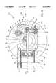
- FIG. 1is a cross-sectional view of a reciprocating machine, constructed in accordance with a first embodiment of the invention, and functioning as an electrically driven pump;
- FIG. 2Ais a detailed top view of the reciprocating machine of FIG. 1, taken in the direction of arrow 2 therein, wherein the piston thereof is at a forward end of its travel;
- FIG. 2Bis a view similar to that of FIG. 2A, but showing the piston close to a rear end of its travel;
- FIG. 3Ais a graph representation of piston velocity versus piston position
- FIG. 3B(i)is a diagram of a prior art system
- FIG. 3B(ii)is a diagram of a system of the present invention.
- FIG. 4Ais a view similar to that of FIG. 2B, but partially cut away so as to show the power output shaft of the power source therein in a first position, providing a maximum piston travel;
- FIG. 4Bis a view similar to that of FIG. 4A, but wherein the power output shaft is in a second position, providing a reduced piston travel;
- FIG. 5is a cross-sectional view of a reciprocating machine, constructed in accordance with a second embodiment of the invention, and functioning as an electrically driven bi-directional pump.
- machine 10which is employed for converting linear motion to rotary motion or vice-versa.
- machine 10has a first end 12, which is preferably associated with a supply of working fluid (not shown), and a second end 14, which is associated with a rotational power source, referenced 16.
- power source 16has a rotational motion transfer member 18.
- machine 10is exemplified by a pump, wherein power source 16 is an electric motor which has a power output shaft 20 on which is mounted a rotary member in the form of a flywheel 22 to which motion transfer member 18 is connected, and which is operative to rotate motion transfer member 18 so as to provide a pumping head at first end 12, associated with the supply of working fluid.
- power source 16is an electric motor which has a power output shaft 20 on which is mounted a rotary member in the form of a flywheel 22 to which motion transfer member 18 is connected, and which is operative to rotate motion transfer member 18 so as to provide a pumping head at first end 12, associated with the supply of working fluid.
- the working fluidis operative to drive the machine 10, such that power source 16 supplies power not to the machine, but is itself powered by the machine and is used to supply power to an external device.
- power source 16may be any sort of motor or electrical generator.
- first end 12 thereofis associated with a working fluid
- the present inventioncould be usefully employed as another type of machine, in which a working member is driven by the machine, via a reciprocating member.
- a working membercould be a sewing machine, for example, or any other machine in which a reciprocating motion of a working member is desired.
- the reciprocating memberwould be guided along a linear path by a guide member.
- the reciprocating machineis formed of a bottom housing portion 11 and a top housing portion 13, which are sealed together, and which are closed at first end 12, by a valve plate 15.
- a cylinder 24, having a longitudinal axis 26,is located within and fastened to bottom housing portion 11.
- Cylinder 24has a first end 28, adjacent to first end 12 of the machine, and a second end 30.
- Working fluid input and output ports, respectively referenced 32 and 34 (FIG. 1),are located at first end 28, and each is provided with a one-way umbrella valve, respectively referenced 32' and 34'.
- a piston 36is located within the cylinder 24, and is arranged for linear, reciprocating travel along longitudinal axis 26, between the first and second ends 28 and 30, respectively, of cylinder 24.
- a reciprocatory memberin the form of a connecting rod 38, having a first end 40 which is connected to the piston 36 via a pivot 42.
- Connecting rod 38also has a transverse extension 44, which extends laterally from the remainder of connecting rod 38 via an elbow 46, and terminates at second end 48.
- piston 36has associated therewith a working member (not shown) and functions as a drive member, and cylinder 24 functions solely as a linear guide therefor.
- a linkage systemis arranged between the connecting rod 38, and the motion transfer member 18, for converting between the linear motion of the piston 36 and rotary motion of the motion transfer member 18.
- the linkage system of the present inventionis characterized by a plurality of pivots which are operative to absorb substantially all those force components which result from rotation of the motion transfer member 18, and which are non-axial in relation to the longitudinal axis 26, thereby to maintain the connecting rod 38 in generally coaxial alignment with the longitudinal axis 26, and thus to substantially prevent side loading of the piston 36 during travel in the cylinder 24.
- crank member 50has a first end 54 connected via a first pivot 56 to the motion transfer member 18 so as to be rotatably driven thereby, and further has a second end 58 connected via a second pivot 60 to the elbow 46 of the connecting rod 38.
- Alignment member 52typically has a generally U-shaped configuration, and has first and second ends, respectively referenced 62 and 64. The first end 62 of alignment member 52 is connected, via a third pivot 66, to the second end 48 of the transverse extension 44 of the connecting rod 38, and the second end 64 of member 52 is connected via a fourth pivot 68 to bottom housing portion 11.
- the alignment member 52preferably extends transversely across the longitudinal axis 26, thereby to add to the compactness of the machine construction.
- first, second, third and fourth pivotsrespectively referenced 56, 60, 66 and 68, respectively define first, second, third and fourth parallel pivot axes, respectively referenced 56', 60', 66' and 68', which are transverse, preferably perpendicular, to longitudinal axis 26.
- first end 40 of the connecting rod 38is connected to the piston 36 via the pivot 42, which defines a fifth pivot axis 42', parallel to the described first, second, third and fourth pivot axes, and that first end 40 of connecting rod 38 is connected to pivot 42 so as to be slidable along the pivot axis 42'.
- all of the first, second, third and fourth pivotsare provided by ball bearing constructions.
- first end 62 of alignment member 52is pivotally connected to the second end 48 of the connecting rod 38, and that second end 64 of alignment member 52 is pivotally connected to bottom housing portion 11.
- the alignment memberextends transversely across the longitudinal axis 26 of connecting rod 38 such that a line through the two pivotal ends 66, 68 of the alignment member assumes the angle (in one direction with respect to axis 26 in one limit position of the connecting rod, and the same angle) in the opposite direction with respect to axis 26 in the opposite limit position of the connecting rod. Accordingly, when the machine is operated, such that crank member 50 is rotated, as indicated by arrow 70 (FIGS.
- piston 36In operation as a pump, as piston 36 moves to the rear end of its travel, as illustrated in FIG. 2B, it draws a working fluid through inlet port 32 and into the cylinder 24, via one way umbrella valve 32'. On its return stroke, piston 36 is operative to pump the working fluid out through outlet port 34 through one way umbrella valve 34'. It will be appreciated that the illustrated machine 10, when operating as a pump, can be used either to build a high positive pressure at outlet port 34, or to provide a vacuum at inlet port 32.
- the above-described reciprocating machinecan also function as a motor, such as a gasoline engine, in which, rather than the piston driving a working fluid (as in the described pump embodiment), different valving is instead employed to reciprocally drive the piston.
- a motorsuch as a gasoline engine
- different valvingis instead employed to reciprocally drive the piston.
- an electrical generatorin place of the illustrated electric motor 16.
- the unique linkage system of the present inventionincludes a total of five pivot locations, one of which has a double function as a radial slide, which together prevent side loading of piston 36.
- the described use of pivots, and, in particular, of ball bearing pivots as shown and described above,are very efficient, free of slack, and are thus quiet.
- the machine of the present inventionis extremely compact, due to the unique construction of the linkage connecting between the motor 16 and the piston 36, without compromising the long piston stroke capacity.
- a major feature of the present inventionis the provision of very slow movement of the piston 36, as seen in the graph of FIG. 3A, in the vicinity of the Top Dead Center (TDC) position, i.e. when the piston 36 is at the uppermost end of the cylinder 24, as seen in FIG. 2A In this position, the valves usually reverse their function from being open to closed or the reverse.
- TDCTop Dead Center
- FIG. 3ABy referring to the graph of FIG. 3A in conjunction with the diagrams in FIG. 3B(i), which represents a prior art system, and FIG. 3B(ii), which represents machine 10 of the present invention, it is clearly seen that in the machine of the present invention, piston 36 exhibits a marked slowdown, relative to the prior art, at TDC -90°; the difference in respective piston velocities is indicated by the areas marked by vertical hatching. It is further seen that in the region 90°-270°, piston 36 exhibits a marked acceleration relative to the prior art; this acceleration relative to the prior art system is indicated by the areas marked by horizontal hatching. Accordingly, while overall piston translation is maintained, the distribution over the piston cycle and thus the exploitation thereof, is far more efficient in the present invention than in the prior art, as described below.
- the travel of the piston in the vicinity of the TDCbe slow, as this allows time for the valves to open or close completely, making their performance efficient. This also reduces both the noise level of the valves and the wear thereof, and, further allows a small pump or motor to perform at higher RPM and thus provide higher performance.
- the above-described slowing of the piston at TDCresults in much more efficient valving, as the opening and closing of the valves can happen over a much longer portion of the cycle as compared with a conventional crank mechanism, such as in a gasoline engine. This enables an increased fluid displacement per revolution when compared with known pumps.
- crank member 50via the motion transfer member 18 (or vice versa).
- end 54 of crank member 50becomes aligned with the longitudinal axis 26 of connecting rod 38 at a location between its end 40 and its pivotal coupling 60 to the crank member, little axial travel of connecting rod 38 is produced as crank member 50 swings through an arc together with motion transfer member 18, therby effecting a reduction in the axial velocity of the connecting rod.
- bottom housing portion 11is connected to the casing of motor 16, and further combines to support fourth pivot 68, and to define a nesting cavity for cylinder 24.
- Upper housing portion 13is essentially a cover for bottom housing portion 11, and is not required for the operation of the machine 10.
- a valve plate 15is connected to upper housing portion 13 and bottom housing portion 11 with screws 72 (FIGS. 2A and 2B).
- the piston traveland thus the pump displacement, may be decreased by moving the center of motor 16 radially outward and forward from location A (FIG. 4A) to location B (FIG. 4B) in the direction of arrow C (FIG. 4A).
- power output shaft 20is initially aligned such that its axis of rotation 21 intersects with longitudinal axis 26.
- piston 36travels along the complete axial length of cylinder 24, thus providing the maximum displacement available for the machine.
- FIG. 4Bit is seen that the position of power output shaft 20 has been moved, in radially outward and forward directions, such that axis of rotation 21 no longer intersects with longitudinal axis 26.
- the most rearward position of piston 36is forward of the rear end 25 of cylinder 24, such that the piston stroke or displacement is shortened.
- Adjustment of the power output shaftis provided by changing the relative positions of the entire power source 16 relative to the housing portion 11. This may be done either by providing several screw holes, shown schematically at 80 and 80', in FIGS. 4A and 4B, into which screw-type fasteners 82 may be inserted, or by any other suitable mechanism.
- FIG. 5in which is shown an electrically driven bi-directional or double acting pump, referenced generally 100.
- pump 100is similar to pump 10 shown and described above in conjunction with FIGS. 1-3, and is thus not described again herein in detail.
- Components of pump 100 seen in any of FIGS. 1-2B,are denoted in FIG. 5 with corresponding referenced numeral with the addition of a prime (') suffix.
- Pump 100differs from pump 10 in that it is constructed to be a bi-directional pump, and thus has a valve plate 15' on both ends. Accordingly, piston 36' is operative to pump fluid in both directions, thereby to double the pump output as compared with that of machine 10.
- a rear housing portion, referenced generally 102, in which the crank mechanism is locatedhas a relatively large volume relative to the volume of cylinder 24'. Due to the relatively large volume of rear housing portion 102, piston 36' is operative to stop pumping on the backstroke when the pressure in housing portion 102 reaches a predetermined magnitude, and so as to merely compress and release the working fluid during reciprocation.
- the interior of rear housing portion 102is hermetically sealed, together with the remainder of the housing, so as to function as an extension of the volume of cylinder 24'. This is facilitated by provision of large opening 104 provided between rear housing portion 102 and piston 36', through which connecting rod 38' extends.
Landscapes
- Engineering & Computer Science (AREA)
- General Engineering & Computer Science (AREA)
- Mechanical Engineering (AREA)
- Chemical & Material Sciences (AREA)
- Combustion & Propulsion (AREA)
- Transmission Devices (AREA)
- Eye Examination Apparatus (AREA)
- Compressors, Vaccum Pumps And Other Relevant Systems (AREA)
- Dry Shavers And Clippers (AREA)
- Reciprocating Pumps (AREA)
- Iron Core Of Rotating Electric Machines (AREA)
- Supercharger (AREA)
- Centrifugal Separators (AREA)
Abstract
Description
Claims (34)
Priority Applications (11)
| Application Number | Priority Date | Filing Date | Title |
|---|---|---|---|
| US08/632,838US5762480A (en) | 1996-04-16 | 1996-04-16 | Reciprocating machine |
| PCT/IL1997/000119WO1997039241A1 (en) | 1996-04-16 | 1997-04-03 | Reciprocating machine |
| UA98010269AUA37285C2 (en) | 1996-04-16 | 1997-04-03 | mechanism for transformation of reciprocal motion to rotary one and vice VERSA AND machine (vAriAnTs) That includes this mechanism |
| GEAP19974101AGEP20002196B (en) | 1996-04-16 | 1997-04-03 | Mechanism for Transforming Movement |
| DE69733403TDE69733403T2 (en) | 1996-04-16 | 1997-04-03 | ROTATING MACHINE |
| CA002228092ACA2228092C (en) | 1996-04-16 | 1997-04-03 | Reciprocating machine |
| AT97914536TATE296957T1 (en) | 1996-04-16 | 1997-04-03 | BACK AND FORTH MACHINE |
| AU21757/97AAU720027B2 (en) | 1996-04-16 | 1997-04-03 | Reciprocating machine |
| CN97190695ACN1073212C (en) | 1996-04-16 | 1997-04-03 | Reciprocating machine |
| EA199800069AEA000159B1 (en) | 1996-04-16 | 1997-04-03 | A motion mechanism for converting reciprocating motion unto rotary motion and vice versa |
| EP97914536AEP0846226B1 (en) | 1996-04-16 | 1997-04-03 | Reciprocating machine |
Applications Claiming Priority (1)
| Application Number | Priority Date | Filing Date | Title |
|---|---|---|---|
| US08/632,838US5762480A (en) | 1996-04-16 | 1996-04-16 | Reciprocating machine |
Publications (1)
| Publication Number | Publication Date |
|---|---|
| US5762480Atrue US5762480A (en) | 1998-06-09 |
Family
ID=24537165
Family Applications (1)
| Application Number | Title | Priority Date | Filing Date |
|---|---|---|---|
| US08/632,838Expired - LifetimeUS5762480A (en) | 1996-04-16 | 1996-04-16 | Reciprocating machine |
Country Status (11)
| Country | Link |
|---|---|
| US (1) | US5762480A (en) |
| EP (1) | EP0846226B1 (en) |
| CN (1) | CN1073212C (en) |
| AT (1) | ATE296957T1 (en) |
| AU (1) | AU720027B2 (en) |
| CA (1) | CA2228092C (en) |
| DE (1) | DE69733403T2 (en) |
| EA (1) | EA000159B1 (en) |
| GE (1) | GEP20002196B (en) |
| UA (1) | UA37285C2 (en) |
| WO (1) | WO1997039241A1 (en) |
Cited By (130)
| Publication number | Priority date | Publication date | Assignee | Title |
|---|---|---|---|---|
| US6234774B1 (en)* | 1996-11-11 | 2001-05-22 | Roberto Siviero | Coaxial valve-type alternating pump especially for boats such as a rubber dinghy, manually operated or motor-driven |
| US6289857B1 (en) | 2000-02-23 | 2001-09-18 | Ford Global Technologies, Inc. | Variable capacity reciprocating engine |
| WO2003048577A1 (en)* | 2001-12-03 | 2003-06-12 | Carmeli Adahan | Double action pump |
| US20030205150A1 (en)* | 2002-05-01 | 2003-11-06 | Murata Kikai Kabushiki Kaisha | Motor driven link press |
| US20040065308A1 (en)* | 1996-07-17 | 2004-04-08 | Bryant Clyde C. | Internal combustion engine and working cycle |
| WO2004111455A1 (en)* | 2003-06-18 | 2004-12-23 | Carmeli Adahan | Single-vane rotary pump or motor |
| US20060082682A1 (en)* | 2004-10-15 | 2006-04-20 | Hoodman Corporation | Camera LCD screen viewing device |
| US7178492B2 (en) | 2002-05-14 | 2007-02-20 | Caterpillar Inc | Air and fuel supply system for combustion engine |
| US7191743B2 (en) | 2002-05-14 | 2007-03-20 | Caterpillar Inc | Air and fuel supply system for a combustion engine |
| US7201121B2 (en) | 2002-02-04 | 2007-04-10 | Caterpillar Inc | Combustion engine including fluidically-driven engine valve actuator |
| US20070079791A1 (en)* | 2005-10-07 | 2007-04-12 | Bradley Raether | WaveTech engine |
| US7204213B2 (en) | 2002-05-14 | 2007-04-17 | Caterpillar Inc | Air and fuel supply system for combustion engine |
| US7222614B2 (en) | 1996-07-17 | 2007-05-29 | Bryant Clyde C | Internal combustion engine and working cycle |
| US20070148016A1 (en)* | 2005-12-22 | 2007-06-28 | Newport Medical Instruments, Inc. | Reciprocating drive apparatus and method |
| US7252054B2 (en) | 2002-05-14 | 2007-08-07 | Caterpillar Inc | Combustion engine including cam phase-shifting |
| US20080078390A1 (en)* | 2006-09-29 | 2008-04-03 | Nellcor Puritan Bennett Incorporated | Providing predetermined groups of trending parameters for display in a breathing assistance system |
| US20080141801A1 (en)* | 2005-10-07 | 2008-06-19 | Wavetech Engines, Inc. | Systems and methods for facilitating conversion between reciprocating linear motion and rotational motion |
| CN100418752C (en)* | 2002-05-01 | 2008-09-17 | 村田机械株式会社 | Motor-driven connecting rod presses |
| US20080308177A1 (en)* | 2007-06-15 | 2008-12-18 | Thuot Raechell M | Hand-held vacuum pump |
| US20090016913A1 (en)* | 2007-07-11 | 2009-01-15 | Gast Manufacturing, Inc., A Division Of Idex Corporation | Balanced dual rocking piston pumps |
| US20090155106A1 (en)* | 2007-12-12 | 2009-06-18 | Caterpillar Inc. | Extended compressor operation for auxiliary air supply |
| US20090205663A1 (en)* | 2008-02-19 | 2009-08-20 | Nellcor Puritan Bennett Llc | Configuring the operation of an alternating pressure ventilation mode |
| US20090247848A1 (en)* | 2008-03-31 | 2009-10-01 | Nellcor Puritan Bennett Llc | Reducing Nuisance Alarms |
| US20100071689A1 (en)* | 2008-09-23 | 2010-03-25 | Ron Thiessen | Safe standby mode for ventilator |
| US20100081119A1 (en)* | 2008-09-30 | 2010-04-01 | Nellcor Puritan Bennett Llc | Configurable respiratory muscle pressure generator |
| US20100078017A1 (en)* | 2008-09-30 | 2010-04-01 | Nellcor Puritan Bennett Llc | Wireless communications for a breathing assistance system |
| US20100139660A1 (en)* | 2008-12-10 | 2010-06-10 | Carmeli Adahan | Pump and exhalation valve control for respirator apparatus |
| US20100249549A1 (en)* | 2009-03-24 | 2010-09-30 | Nellcor Puritan Bennett Llc | Indicating The Accuracy Of A Physiological Parameter |
| US20110006719A1 (en)* | 2009-07-07 | 2011-01-13 | Fanuc Ltd | Press machine controller |
| US20110023878A1 (en)* | 2009-07-31 | 2011-02-03 | Nellcor Puritan Bennett Llc | Method And System For Delivering A Single-Breath, Low Flow Recruitment Maneuver |
| US20110041850A1 (en)* | 2009-08-20 | 2011-02-24 | Nellcor Puritan Bennett Llc | Method For Ventilation |
| US20110132364A1 (en)* | 2009-12-03 | 2011-06-09 | Nellcor Puritan Bennett Llc | Ventilator Respiratory Gas Accumulator With Dip Tube |
| US20110133936A1 (en)* | 2009-12-04 | 2011-06-09 | Nellcor Puritan Bennett Llc | Interactive Multilevel Alarm |
| US20110146683A1 (en)* | 2009-12-21 | 2011-06-23 | Nellcor Puritan Bennett Llc | Sensor Model |
| US20110146681A1 (en)* | 2009-12-21 | 2011-06-23 | Nellcor Puritan Bennett Llc | Adaptive Flow Sensor Model |
| US20110175728A1 (en)* | 2010-01-19 | 2011-07-21 | Nellcor Puritan Bennett Llc | Nuisance Alarm Reduction Method For Therapeutic Parameters |
| US8215292B2 (en) | 1996-07-17 | 2012-07-10 | Bryant Clyde C | Internal combustion engine and working cycle |
| US8421465B2 (en) | 2009-12-02 | 2013-04-16 | Covidien Lp | Method and apparatus for indicating battery cell status on a battery pack assembly used during mechanical ventilation |
| US8418692B2 (en) | 2009-12-04 | 2013-04-16 | Covidien Lp | Ventilation system with removable primary display |
| US8418691B2 (en) | 2009-03-20 | 2013-04-16 | Covidien Lp | Leak-compensated pressure regulated volume control ventilation |
| US8424521B2 (en) | 2009-02-27 | 2013-04-23 | Covidien Lp | Leak-compensated respiratory mechanics estimation in medical ventilators |
| US8425428B2 (en) | 2008-03-31 | 2013-04-23 | Covidien Lp | Nitric oxide measurements in patients using flowfeedback |
| US8434479B2 (en) | 2009-02-27 | 2013-05-07 | Covidien Lp | Flow rate compensation for transient thermal response of hot-wire anemometers |
| US8434480B2 (en) | 2008-03-31 | 2013-05-07 | Covidien Lp | Ventilator leak compensation |
| US8439036B2 (en) | 2009-12-01 | 2013-05-14 | Covidien Lp | Exhalation valve assembly with integral flow sensor |
| US8443294B2 (en) | 2009-12-18 | 2013-05-14 | Covidien Lp | Visual indication of alarms on a ventilator graphical user interface |
| US8439037B2 (en) | 2009-12-01 | 2013-05-14 | Covidien Lp | Exhalation valve assembly with integrated filter and flow sensor |
| US8448641B2 (en) | 2009-03-20 | 2013-05-28 | Covidien Lp | Leak-compensated proportional assist ventilation |
| US8453645B2 (en) | 2006-09-26 | 2013-06-04 | Covidien Lp | Three-dimensional waveform display for a breathing assistance system |
| US8453643B2 (en) | 2010-04-27 | 2013-06-04 | Covidien Lp | Ventilation system with system status display for configuration and program information |
| US8469031B2 (en) | 2009-12-01 | 2013-06-25 | Covidien Lp | Exhalation valve assembly with integrated filter |
| US8469030B2 (en) | 2009-12-01 | 2013-06-25 | Covidien Lp | Exhalation valve assembly with selectable contagious/non-contagious latch |
| US8485185B2 (en) | 2008-06-06 | 2013-07-16 | Covidien Lp | Systems and methods for ventilation in proportion to patient effort |
| US8511306B2 (en) | 2010-04-27 | 2013-08-20 | Covidien Lp | Ventilation system with system status display for maintenance and service information |
| US8528554B2 (en) | 2008-09-04 | 2013-09-10 | Covidien Lp | Inverse sawtooth pressure wave train purging in medical ventilators |
| US8539949B2 (en) | 2010-04-27 | 2013-09-24 | Covidien Lp | Ventilation system with a two-point perspective view |
| US8554298B2 (en) | 2010-09-21 | 2013-10-08 | Cividien LP | Medical ventilator with integrated oximeter data |
| US8551006B2 (en) | 2008-09-17 | 2013-10-08 | Covidien Lp | Method for determining hemodynamic effects |
| US8555882B2 (en) | 1997-03-14 | 2013-10-15 | Covidien Lp | Ventilator breath display and graphic user interface |
| USD692556S1 (en) | 2013-03-08 | 2013-10-29 | Covidien Lp | Expiratory filter body of an exhalation module |
| USD693001S1 (en) | 2013-03-08 | 2013-11-05 | Covidien Lp | Neonate expiratory filter assembly of an exhalation module |
| US8595639B2 (en) | 2010-11-29 | 2013-11-26 | Covidien Lp | Ventilator-initiated prompt regarding detection of fluctuations in resistance |
| US8597198B2 (en) | 2006-04-21 | 2013-12-03 | Covidien Lp | Work of breathing display for a ventilation system |
| US8607789B2 (en) | 2010-06-30 | 2013-12-17 | Covidien Lp | Ventilator-initiated prompt regarding auto-PEEP detection during volume ventilation of non-triggering patient exhibiting obstructive component |
| US8607791B2 (en) | 2010-06-30 | 2013-12-17 | Covidien Lp | Ventilator-initiated prompt regarding auto-PEEP detection during pressure ventilation |
| US8607788B2 (en) | 2010-06-30 | 2013-12-17 | Covidien Lp | Ventilator-initiated prompt regarding auto-PEEP detection during volume ventilation of triggering patient exhibiting obstructive component |
| US8607790B2 (en) | 2010-06-30 | 2013-12-17 | Covidien Lp | Ventilator-initiated prompt regarding auto-PEEP detection during pressure ventilation of patient exhibiting obstructive component |
| US8638200B2 (en) | 2010-05-07 | 2014-01-28 | Covidien Lp | Ventilator-initiated prompt regarding Auto-PEEP detection during volume ventilation of non-triggering patient |
| US8640700B2 (en) | 2008-03-27 | 2014-02-04 | Covidien Lp | Method for selecting target settings in a medical device |
| US8652064B2 (en) | 2008-09-30 | 2014-02-18 | Covidien Lp | Sampling circuit for measuring analytes |
| US8676285B2 (en) | 2010-07-28 | 2014-03-18 | Covidien Lp | Methods for validating patient identity |
| US8676529B2 (en) | 2011-01-31 | 2014-03-18 | Covidien Lp | Systems and methods for simulation and software testing |
| USD701601S1 (en) | 2013-03-08 | 2014-03-25 | Covidien Lp | Condensate vial of an exhalation module |
| US8707952B2 (en) | 2010-02-10 | 2014-04-29 | Covidien Lp | Leak determination in a breathing assistance system |
| US8714154B2 (en) | 2011-03-30 | 2014-05-06 | Covidien Lp | Systems and methods for automatic adjustment of ventilator settings |
| US8720442B2 (en) | 2008-09-26 | 2014-05-13 | Covidien Lp | Systems and methods for managing pressure in a breathing assistance system |
| US8746248B2 (en) | 2008-03-31 | 2014-06-10 | Covidien Lp | Determination of patient circuit disconnect in leak-compensated ventilatory support |
| US8757153B2 (en) | 2010-11-29 | 2014-06-24 | Covidien Lp | Ventilator-initiated prompt regarding detection of double triggering during ventilation |
| US8757152B2 (en) | 2010-11-29 | 2014-06-24 | Covidien Lp | Ventilator-initiated prompt regarding detection of double triggering during a volume-control breath type |
| US8776790B2 (en) | 2009-07-16 | 2014-07-15 | Covidien Lp | Wireless, gas flow-powered sensor system for a breathing assistance system |
| US8776792B2 (en) | 2011-04-29 | 2014-07-15 | Covidien Lp | Methods and systems for volume-targeted minimum pressure-control ventilation |
| US8788236B2 (en) | 2011-01-31 | 2014-07-22 | Covidien Lp | Systems and methods for medical device testing |
| US8783250B2 (en) | 2011-02-27 | 2014-07-22 | Covidien Lp | Methods and systems for transitory ventilation support |
| US8794234B2 (en) | 2008-09-25 | 2014-08-05 | Covidien Lp | Inversion-based feed-forward compensation of inspiratory trigger dynamics in medical ventilators |
| US8800557B2 (en) | 2003-07-29 | 2014-08-12 | Covidien Lp | System and process for supplying respiratory gas under pressure or volumetrically |
| US8844526B2 (en) | 2012-03-30 | 2014-09-30 | Covidien Lp | Methods and systems for triggering with unknown base flow |
| US8902568B2 (en) | 2006-09-27 | 2014-12-02 | Covidien Lp | Power supply interface system for a breathing assistance system |
| US8924878B2 (en) | 2009-12-04 | 2014-12-30 | Covidien Lp | Display and access to settings on a ventilator graphical user interface |
| US8950398B2 (en) | 2008-09-30 | 2015-02-10 | Covidien Lp | Supplemental gas safety system for a breathing assistance system |
| US9022031B2 (en) | 2012-01-31 | 2015-05-05 | Covidien Lp | Using estimated carinal pressure for feedback control of carinal pressure during ventilation |
| US9027552B2 (en) | 2012-07-31 | 2015-05-12 | Covidien Lp | Ventilator-initiated prompt or setting regarding detection of asynchrony during ventilation |
| US9038633B2 (en) | 2011-03-02 | 2015-05-26 | Covidien Lp | Ventilator-initiated prompt regarding high delivered tidal volume |
| USD731049S1 (en) | 2013-03-05 | 2015-06-02 | Covidien Lp | EVQ housing of an exhalation module |
| USD731048S1 (en) | 2013-03-08 | 2015-06-02 | Covidien Lp | EVQ diaphragm of an exhalation module |
| USD731065S1 (en) | 2013-03-08 | 2015-06-02 | Covidien Lp | EVQ pressure sensor filter of an exhalation module |
| US9084865B2 (en) | 2004-09-15 | 2015-07-21 | Covidien Ag | System and method for regulating a heating humidifier |
| US9089657B2 (en) | 2011-10-31 | 2015-07-28 | Covidien Lp | Methods and systems for gating user initiated increases in oxygen concentration during ventilation |
| USD736905S1 (en) | 2013-03-08 | 2015-08-18 | Covidien Lp | Exhalation module EVQ housing |
| US9119925B2 (en) | 2009-12-04 | 2015-09-01 | Covidien Lp | Quick initiation of respiratory support via a ventilator user interface |
| US9144658B2 (en) | 2012-04-30 | 2015-09-29 | Covidien Lp | Minimizing imposed expiratory resistance of mechanical ventilator by optimizing exhalation valve control |
| US9194468B1 (en)* | 2014-09-30 | 2015-11-24 | Peter Fan | Slider-crank mechanism with L-shaped connecting rod |
| USD744095S1 (en) | 2013-03-08 | 2015-11-24 | Covidien Lp | Exhalation module EVQ internal flow sensor |
| US9262588B2 (en) | 2009-12-18 | 2016-02-16 | Covidien Lp | Display of respiratory data graphs on a ventilator graphical user interface |
| US9269990B2 (en) | 2008-09-30 | 2016-02-23 | Covidien Lp | Battery management for a breathing assistance system |
| US9289573B2 (en) | 2012-12-28 | 2016-03-22 | Covidien Lp | Ventilator pressure oscillation filter |
| US9302061B2 (en) | 2010-02-26 | 2016-04-05 | Covidien Lp | Event-based delay detection and control of networked systems in medical ventilation |
| US9327089B2 (en) | 2012-03-30 | 2016-05-03 | Covidien Lp | Methods and systems for compensation of tubing related loss effects |
| US9358355B2 (en) | 2013-03-11 | 2016-06-07 | Covidien Lp | Methods and systems for managing a patient move |
| US9364624B2 (en) | 2011-12-07 | 2016-06-14 | Covidien Lp | Methods and systems for adaptive base flow |
| US9375542B2 (en) | 2012-11-08 | 2016-06-28 | Covidien Lp | Systems and methods for monitoring, managing, and/or preventing fatigue during ventilation |
| US9492629B2 (en) | 2013-02-14 | 2016-11-15 | Covidien Lp | Methods and systems for ventilation with unknown exhalation flow and exhalation pressure |
| US9498589B2 (en) | 2011-12-31 | 2016-11-22 | Covidien Lp | Methods and systems for adaptive base flow and leak compensation |
| USD775345S1 (en) | 2015-04-10 | 2016-12-27 | Covidien Lp | Ventilator console |
| RU2610319C1 (en)* | 2015-11-16 | 2017-02-09 | Валерий Федорович Смирнов | Device for conversion of reciprocating movement to rotational movement and vice versa |
| US9629971B2 (en) | 2011-04-29 | 2017-04-25 | Covidien Lp | Methods and systems for exhalation control and trajectory optimization |
| US9649458B2 (en) | 2008-09-30 | 2017-05-16 | Covidien Lp | Breathing assistance system with multiple pressure sensors |
| US9675771B2 (en) | 2013-10-18 | 2017-06-13 | Covidien Lp | Methods and systems for leak estimation |
| US9808591B2 (en) | 2014-08-15 | 2017-11-07 | Covidien Lp | Methods and systems for breath delivery synchronization |
| US20180030967A1 (en)* | 2016-07-29 | 2018-02-01 | Wagner Spray Tech Corporation | Aligning reciprocating motion in fluid delivery systems |
| US9925346B2 (en) | 2015-01-20 | 2018-03-27 | Covidien Lp | Systems and methods for ventilation with unknown exhalation flow |
| US9950129B2 (en) | 2014-10-27 | 2018-04-24 | Covidien Lp | Ventilation triggering using change-point detection |
| US9950135B2 (en) | 2013-03-15 | 2018-04-24 | Covidien Lp | Maintaining an exhalation valve sensor assembly |
| US9981096B2 (en) | 2013-03-13 | 2018-05-29 | Covidien Lp | Methods and systems for triggering with unknown inspiratory flow |
| US9993604B2 (en) | 2012-04-27 | 2018-06-12 | Covidien Lp | Methods and systems for an optimized proportional assist ventilation |
| US10064583B2 (en) | 2013-08-07 | 2018-09-04 | Covidien Lp | Detection of expiratory airflow limitation in ventilated patient |
| US10207069B2 (en) | 2008-03-31 | 2019-02-19 | Covidien Lp | System and method for determining ventilator leakage during stable periods within a breath |
| US10362967B2 (en) | 2012-07-09 | 2019-07-30 | Covidien Lp | Systems and methods for missed breath detection and indication |
| US10668239B2 (en) | 2017-11-14 | 2020-06-02 | Covidien Lp | Systems and methods for drive pressure spontaneous ventilation |
| US10765822B2 (en) | 2016-04-18 | 2020-09-08 | Covidien Lp | Endotracheal tube extubation detection |
| US12378370B2 (en) | 2017-09-11 | 2025-08-05 | Tomgrow Ltd. | Hydrogel and uses thereof as a substrate for growing plants |
Families Citing this family (6)
| Publication number | Priority date | Publication date | Assignee | Title |
|---|---|---|---|---|
| US8550794B2 (en)* | 2010-08-09 | 2013-10-08 | Foothill Land, Llc | Double acting fluid pump |
| WO2012155068A2 (en)* | 2011-05-11 | 2012-11-15 | Nereid S.A. | A positive displacement multi-cyclinder pump |
| RU170792U1 (en)* | 2016-07-27 | 2017-05-11 | Борис Андреевич Шахов | GAS COMPRESSOR INSTALLATION |
| CN106286185B (en)* | 2016-08-19 | 2018-09-11 | 武汉理工大学 | A kind of four cylinder constant flow reciprocating pump gear unit of radial direction |
| CN110454348B (en)* | 2019-09-13 | 2024-06-28 | 西南石油大学 | Ultra-long stroke multi-cylinder reciprocating pump |
| CN115435056B (en)* | 2022-09-15 | 2025-05-20 | 中钢集团西安重机有限公司 | Angle adjusting method of alignment mechanism |
Citations (12)
| Publication number | Priority date | Publication date | Assignee | Title |
|---|---|---|---|---|
| US2233857A (en)* | 1939-08-24 | 1941-03-04 | Irving J Mcguire | Internal combustion engine |
| US2548296A (en)* | 1948-04-12 | 1951-04-10 | Laura Femons | Connecting rod assembly |
| US2658351A (en)* | 1949-02-03 | 1953-11-10 | Raymond A Hill | Water channel control gate |
| US3105162A (en)* | 1959-06-29 | 1963-09-24 | Donald E Stevenson | Electromagnet motor with crankshaft drive |
| US3176671A (en)* | 1963-01-21 | 1965-04-06 | Hilbee Corp | Internal combustion engine |
| US3633429A (en)* | 1970-06-08 | 1972-01-11 | Thorvald N Olson | Piston stroke control mechanism |
| US4300405A (en)* | 1979-04-05 | 1981-11-17 | Bauer Kompressoren, Gmbh | Central guide means for the piston of a reciprocating piston machine |
| US4455976A (en)* | 1982-04-06 | 1984-06-26 | Mccandless John H | Internal combustion engines |
| US4517931A (en)* | 1983-06-30 | 1985-05-21 | Nelson Carl D | Variable stroke engine |
| US4608951A (en)* | 1984-12-26 | 1986-09-02 | Ambrose White | Reciprocating piston engine |
| US4979428A (en)* | 1989-05-30 | 1990-12-25 | Nelson Lester R | Reciprocating air compressor with improved drive linkage |
| US5448970A (en)* | 1995-01-12 | 1995-09-12 | Bray; William R. | Crankshaft connection for internal combustion engine |
- 1996
- 1996-04-16USUS08/632,838patent/US5762480A/ennot_activeExpired - Lifetime
- 1997
- 1997-04-03UAUA98010269Apatent/UA37285C2/enunknown
- 1997-04-03EPEP97914536Apatent/EP0846226B1/ennot_activeExpired - Lifetime
- 1997-04-03CNCN97190695Apatent/CN1073212C/ennot_activeExpired - Fee Related
- 1997-04-03WOPCT/IL1997/000119patent/WO1997039241A1/enactiveIP Right Grant
- 1997-04-03AUAU21757/97Apatent/AU720027B2/ennot_activeExpired
- 1997-04-03ATAT97914536Tpatent/ATE296957T1/ennot_activeIP Right Cessation
- 1997-04-03GEGEAP19974101Apatent/GEP20002196B/enunknown
- 1997-04-03CACA002228092Apatent/CA2228092C/ennot_activeExpired - Lifetime
- 1997-04-03DEDE69733403Tpatent/DE69733403T2/ennot_activeExpired - Lifetime
- 1997-04-03EAEA199800069Apatent/EA000159B1/ennot_activeIP Right Cessation
Patent Citations (12)
| Publication number | Priority date | Publication date | Assignee | Title |
|---|---|---|---|---|
| US2233857A (en)* | 1939-08-24 | 1941-03-04 | Irving J Mcguire | Internal combustion engine |
| US2548296A (en)* | 1948-04-12 | 1951-04-10 | Laura Femons | Connecting rod assembly |
| US2658351A (en)* | 1949-02-03 | 1953-11-10 | Raymond A Hill | Water channel control gate |
| US3105162A (en)* | 1959-06-29 | 1963-09-24 | Donald E Stevenson | Electromagnet motor with crankshaft drive |
| US3176671A (en)* | 1963-01-21 | 1965-04-06 | Hilbee Corp | Internal combustion engine |
| US3633429A (en)* | 1970-06-08 | 1972-01-11 | Thorvald N Olson | Piston stroke control mechanism |
| US4300405A (en)* | 1979-04-05 | 1981-11-17 | Bauer Kompressoren, Gmbh | Central guide means for the piston of a reciprocating piston machine |
| US4455976A (en)* | 1982-04-06 | 1984-06-26 | Mccandless John H | Internal combustion engines |
| US4517931A (en)* | 1983-06-30 | 1985-05-21 | Nelson Carl D | Variable stroke engine |
| US4608951A (en)* | 1984-12-26 | 1986-09-02 | Ambrose White | Reciprocating piston engine |
| US4979428A (en)* | 1989-05-30 | 1990-12-25 | Nelson Lester R | Reciprocating air compressor with improved drive linkage |
| US5448970A (en)* | 1995-01-12 | 1995-09-12 | Bray; William R. | Crankshaft connection for internal combustion engine |
Cited By (216)
| Publication number | Priority date | Publication date | Assignee | Title |
|---|---|---|---|---|
| US8215292B2 (en) | 1996-07-17 | 2012-07-10 | Bryant Clyde C | Internal combustion engine and working cycle |
| US20040065308A1 (en)* | 1996-07-17 | 2004-04-08 | Bryant Clyde C. | Internal combustion engine and working cycle |
| US20050098162A1 (en)* | 1996-07-17 | 2005-05-12 | Bryant Clyde C. | Internal combustion engine and working cycle |
| US7281527B1 (en) | 1996-07-17 | 2007-10-16 | Bryant Clyde C | Internal combustion engine and working cycle |
| US7222614B2 (en) | 1996-07-17 | 2007-05-29 | Bryant Clyde C | Internal combustion engine and working cycle |
| US6234774B1 (en)* | 1996-11-11 | 2001-05-22 | Roberto Siviero | Coaxial valve-type alternating pump especially for boats such as a rubber dinghy, manually operated or motor-driven |
| US8555881B2 (en) | 1997-03-14 | 2013-10-15 | Covidien Lp | Ventilator breath display and graphic interface |
| US8555882B2 (en) | 1997-03-14 | 2013-10-15 | Covidien Lp | Ventilator breath display and graphic user interface |
| US6289857B1 (en) | 2000-02-23 | 2001-09-18 | Ford Global Technologies, Inc. | Variable capacity reciprocating engine |
| WO2003048577A1 (en)* | 2001-12-03 | 2003-06-12 | Carmeli Adahan | Double action pump |
| US7201121B2 (en) | 2002-02-04 | 2007-04-10 | Caterpillar Inc | Combustion engine including fluidically-driven engine valve actuator |
| US7028611B2 (en)* | 2002-05-01 | 2006-04-18 | Murata Kikai Kabushiki Kaisha | Motor driven link press |
| CN100418752C (en)* | 2002-05-01 | 2008-09-17 | 村田机械株式会社 | Motor-driven connecting rod presses |
| US20050132903A1 (en)* | 2002-05-01 | 2005-06-23 | Murata Kikai Kabushiki Kaisha | Motor driven link press |
| CN100581801C (en)* | 2002-05-01 | 2010-01-20 | 村田机械株式会社 | Motor-driven connecting rod type press |
| US7004006B2 (en)* | 2002-05-01 | 2006-02-28 | Murata Kikai Kabushiki Kaisha | Motor driven link press |
| US20050132862A1 (en)* | 2002-05-01 | 2005-06-23 | Murata Kikai Kabushiki Kaisha | Motor driven link press |
| US6945165B2 (en)* | 2002-05-01 | 2005-09-20 | Murata Kikai Kabushiki Kaisha | Motor driven link press |
| US20030205150A1 (en)* | 2002-05-01 | 2003-11-06 | Murata Kikai Kabushiki Kaisha | Motor driven link press |
| US20050193904A1 (en)* | 2002-05-01 | 2005-09-08 | Murata Kikai Kabushiki Kaisha | Motor driven link press |
| US7178492B2 (en) | 2002-05-14 | 2007-02-20 | Caterpillar Inc | Air and fuel supply system for combustion engine |
| US7191743B2 (en) | 2002-05-14 | 2007-03-20 | Caterpillar Inc | Air and fuel supply system for a combustion engine |
| US7204213B2 (en) | 2002-05-14 | 2007-04-17 | Caterpillar Inc | Air and fuel supply system for combustion engine |
| US7252054B2 (en) | 2002-05-14 | 2007-08-07 | Caterpillar Inc | Combustion engine including cam phase-shifting |
| WO2004111455A1 (en)* | 2003-06-18 | 2004-12-23 | Carmeli Adahan | Single-vane rotary pump or motor |
| US20060228245A1 (en)* | 2003-06-18 | 2006-10-12 | Carmeli Adahan | Single-vane rotary pump or motor |
| US20080063552A1 (en)* | 2003-06-18 | 2008-03-13 | Carmeli Adahan | Single-vane rotary pump or motor |
| US8800557B2 (en) | 2003-07-29 | 2014-08-12 | Covidien Lp | System and process for supplying respiratory gas under pressure or volumetrically |
| US9084865B2 (en) | 2004-09-15 | 2015-07-21 | Covidien Ag | System and method for regulating a heating humidifier |
| US20060082682A1 (en)* | 2004-10-15 | 2006-04-20 | Hoodman Corporation | Camera LCD screen viewing device |
| US20080141801A1 (en)* | 2005-10-07 | 2008-06-19 | Wavetech Engines, Inc. | Systems and methods for facilitating conversion between reciprocating linear motion and rotational motion |
| US7360521B2 (en) | 2005-10-07 | 2008-04-22 | Wavetech Engines, Inc. | Reciprocating engines |
| US20070079791A1 (en)* | 2005-10-07 | 2007-04-12 | Bradley Raether | WaveTech engine |
| US8171812B2 (en) | 2005-10-07 | 2012-05-08 | Wavetech Engines, Inc. | Systems and methods for facilitating conversion between reciprocating linear motion and rotational motion |
| US20070148016A1 (en)* | 2005-12-22 | 2007-06-28 | Newport Medical Instruments, Inc. | Reciprocating drive apparatus and method |
| US7654802B2 (en) | 2005-12-22 | 2010-02-02 | Newport Medical Instruments, Inc. | Reciprocating drive apparatus and method |
| US10582880B2 (en) | 2006-04-21 | 2020-03-10 | Covidien Lp | Work of breathing display for a ventilation system |
| US8597198B2 (en) | 2006-04-21 | 2013-12-03 | Covidien Lp | Work of breathing display for a ventilation system |
| US8453645B2 (en) | 2006-09-26 | 2013-06-04 | Covidien Lp | Three-dimensional waveform display for a breathing assistance system |
| US8902568B2 (en) | 2006-09-27 | 2014-12-02 | Covidien Lp | Power supply interface system for a breathing assistance system |
| US20080078390A1 (en)* | 2006-09-29 | 2008-04-03 | Nellcor Puritan Bennett Incorporated | Providing predetermined groups of trending parameters for display in a breathing assistance system |
| US8096329B2 (en)* | 2007-06-15 | 2012-01-17 | S. C. Johnson & Son, Inc. | Hand-held vacuum pump |
| US20080308177A1 (en)* | 2007-06-15 | 2008-12-18 | Thuot Raechell M | Hand-held vacuum pump |
| US8328538B2 (en)* | 2007-07-11 | 2012-12-11 | Gast Manufacturing, Inc., A Unit Of Idex Corporation | Balanced dual rocking piston pumps |
| US20090016913A1 (en)* | 2007-07-11 | 2009-01-15 | Gast Manufacturing, Inc., A Division Of Idex Corporation | Balanced dual rocking piston pumps |
| US20090155106A1 (en)* | 2007-12-12 | 2009-06-18 | Caterpillar Inc. | Extended compressor operation for auxiliary air supply |
| US20090205663A1 (en)* | 2008-02-19 | 2009-08-20 | Nellcor Puritan Bennett Llc | Configuring the operation of an alternating pressure ventilation mode |
| US8640700B2 (en) | 2008-03-27 | 2014-02-04 | Covidien Lp | Method for selecting target settings in a medical device |
| US8425428B2 (en) | 2008-03-31 | 2013-04-23 | Covidien Lp | Nitric oxide measurements in patients using flowfeedback |
| US9421338B2 (en) | 2008-03-31 | 2016-08-23 | Covidien Lp | Ventilator leak compensation |
| US8434480B2 (en) | 2008-03-31 | 2013-05-07 | Covidien Lp | Ventilator leak compensation |
| US9820681B2 (en) | 2008-03-31 | 2017-11-21 | Covidien Lp | Reducing nuisance alarms |
| US20090247848A1 (en)* | 2008-03-31 | 2009-10-01 | Nellcor Puritan Bennett Llc | Reducing Nuisance Alarms |
| US11027080B2 (en) | 2008-03-31 | 2021-06-08 | Covidien Lp | System and method for determining ventilator leakage during stable periods within a breath |
| US10207069B2 (en) | 2008-03-31 | 2019-02-19 | Covidien Lp | System and method for determining ventilator leakage during stable periods within a breath |
| US8792949B2 (en) | 2008-03-31 | 2014-07-29 | Covidien Lp | Reducing nuisance alarms |
| US8746248B2 (en) | 2008-03-31 | 2014-06-10 | Covidien Lp | Determination of patient circuit disconnect in leak-compensated ventilatory support |
| US9956363B2 (en) | 2008-06-06 | 2018-05-01 | Covidien Lp | Systems and methods for triggering and cycling a ventilator based on reconstructed patient effort signal |
| US9126001B2 (en) | 2008-06-06 | 2015-09-08 | Covidien Lp | Systems and methods for ventilation in proportion to patient effort |
| US9114220B2 (en) | 2008-06-06 | 2015-08-25 | Covidien Lp | Systems and methods for triggering and cycling a ventilator based on reconstructed patient effort signal |
| US8485183B2 (en) | 2008-06-06 | 2013-07-16 | Covidien Lp | Systems and methods for triggering and cycling a ventilator based on reconstructed patient effort signal |
| US8485184B2 (en) | 2008-06-06 | 2013-07-16 | Covidien Lp | Systems and methods for monitoring and displaying respiratory information |
| US9925345B2 (en) | 2008-06-06 | 2018-03-27 | Covidien Lp | Systems and methods for determining patient effort and/or respiratory parameters in a ventilation system |
| US10828437B2 (en) | 2008-06-06 | 2020-11-10 | Covidien Lp | Systems and methods for triggering and cycling a ventilator based on reconstructed patient effort signal |
| US8826907B2 (en) | 2008-06-06 | 2014-09-09 | Covidien Lp | Systems and methods for determining patient effort and/or respiratory parameters in a ventilation system |
| US8485185B2 (en) | 2008-06-06 | 2013-07-16 | Covidien Lp | Systems and methods for ventilation in proportion to patient effort |
| US8528554B2 (en) | 2008-09-04 | 2013-09-10 | Covidien Lp | Inverse sawtooth pressure wave train purging in medical ventilators |
| US9414769B2 (en) | 2008-09-17 | 2016-08-16 | Covidien Lp | Method for determining hemodynamic effects |
| US8551006B2 (en) | 2008-09-17 | 2013-10-08 | Covidien Lp | Method for determining hemodynamic effects |
| US8424520B2 (en) | 2008-09-23 | 2013-04-23 | Covidien Lp | Safe standby mode for ventilator |
| US10493225B2 (en) | 2008-09-23 | 2019-12-03 | Covidien Lp | Safe standby mode for ventilator |
| US9381314B2 (en) | 2008-09-23 | 2016-07-05 | Covidien Lp | Safe standby mode for ventilator |
| US20100071689A1 (en)* | 2008-09-23 | 2010-03-25 | Ron Thiessen | Safe standby mode for ventilator |
| US11344689B2 (en) | 2008-09-23 | 2022-05-31 | Covidien Lp | Safe standby mode for ventilator |
| US8794234B2 (en) | 2008-09-25 | 2014-08-05 | Covidien Lp | Inversion-based feed-forward compensation of inspiratory trigger dynamics in medical ventilators |
| US8720442B2 (en) | 2008-09-26 | 2014-05-13 | Covidien Lp | Systems and methods for managing pressure in a breathing assistance system |
| US9269990B2 (en) | 2008-09-30 | 2016-02-23 | Covidien Lp | Battery management for a breathing assistance system |
| US8585412B2 (en) | 2008-09-30 | 2013-11-19 | Covidien Lp | Configurable respiratory muscle pressure generator |
| US20100081119A1 (en)* | 2008-09-30 | 2010-04-01 | Nellcor Puritan Bennett Llc | Configurable respiratory muscle pressure generator |
| US20100078017A1 (en)* | 2008-09-30 | 2010-04-01 | Nellcor Puritan Bennett Llc | Wireless communications for a breathing assistance system |
| US8652064B2 (en) | 2008-09-30 | 2014-02-18 | Covidien Lp | Sampling circuit for measuring analytes |
| US8439032B2 (en) | 2008-09-30 | 2013-05-14 | Covidien Lp | Wireless communications for a breathing assistance system |
| US8950398B2 (en) | 2008-09-30 | 2015-02-10 | Covidien Lp | Supplemental gas safety system for a breathing assistance system |
| US9649458B2 (en) | 2008-09-30 | 2017-05-16 | Covidien Lp | Breathing assistance system with multiple pressure sensors |
| US8303276B2 (en) | 2008-12-10 | 2012-11-06 | Covidien Lp | Pump and exhalation valve control for respirator apparatus |
| US20100139660A1 (en)* | 2008-12-10 | 2010-06-10 | Carmeli Adahan | Pump and exhalation valve control for respirator apparatus |
| DE112009003558T5 (en) | 2008-12-10 | 2013-01-31 | Newport Medical Instruments, Inc. | Pump and exhalation valve control for respirator |
| US8434479B2 (en) | 2009-02-27 | 2013-05-07 | Covidien Lp | Flow rate compensation for transient thermal response of hot-wire anemometers |
| US8424521B2 (en) | 2009-02-27 | 2013-04-23 | Covidien Lp | Leak-compensated respiratory mechanics estimation in medical ventilators |
| US8905024B2 (en) | 2009-02-27 | 2014-12-09 | Covidien Lp | Flow rate compensation for transient thermal response of hot-wire anemometers |
| US8418691B2 (en) | 2009-03-20 | 2013-04-16 | Covidien Lp | Leak-compensated pressure regulated volume control ventilation |
| US8448641B2 (en) | 2009-03-20 | 2013-05-28 | Covidien Lp | Leak-compensated proportional assist ventilation |
| US8978650B2 (en) | 2009-03-20 | 2015-03-17 | Covidien Lp | Leak-compensated proportional assist ventilation |
| US8973577B2 (en) | 2009-03-20 | 2015-03-10 | Covidien Lp | Leak-compensated pressure regulated volume control ventilation |
| US9186075B2 (en)* | 2009-03-24 | 2015-11-17 | Covidien Lp | Indicating the accuracy of a physiological parameter |
| US20100249549A1 (en)* | 2009-03-24 | 2010-09-30 | Nellcor Puritan Bennett Llc | Indicating The Accuracy Of A Physiological Parameter |
| US20110006719A1 (en)* | 2009-07-07 | 2011-01-13 | Fanuc Ltd | Press machine controller |
| US8049457B2 (en)* | 2009-07-07 | 2011-11-01 | Fanuc Ltd | Press machine controller |
| US8776790B2 (en) | 2009-07-16 | 2014-07-15 | Covidien Lp | Wireless, gas flow-powered sensor system for a breathing assistance system |
| US20110023878A1 (en)* | 2009-07-31 | 2011-02-03 | Nellcor Puritan Bennett Llc | Method And System For Delivering A Single-Breath, Low Flow Recruitment Maneuver |
| US8789529B2 (en) | 2009-08-20 | 2014-07-29 | Covidien Lp | Method for ventilation |
| US20110041850A1 (en)* | 2009-08-20 | 2011-02-24 | Nellcor Puritan Bennett Llc | Method For Ventilation |
| US8439036B2 (en) | 2009-12-01 | 2013-05-14 | Covidien Lp | Exhalation valve assembly with integral flow sensor |
| US9205221B2 (en) | 2009-12-01 | 2015-12-08 | Covidien Lp | Exhalation valve assembly with integral flow sensor |
| US9987457B2 (en) | 2009-12-01 | 2018-06-05 | Covidien Lp | Exhalation valve assembly with integral flow sensor |
| US8469031B2 (en) | 2009-12-01 | 2013-06-25 | Covidien Lp | Exhalation valve assembly with integrated filter |
| US8469030B2 (en) | 2009-12-01 | 2013-06-25 | Covidien Lp | Exhalation valve assembly with selectable contagious/non-contagious latch |
| US8439037B2 (en) | 2009-12-01 | 2013-05-14 | Covidien Lp | Exhalation valve assembly with integrated filter and flow sensor |
| US8421465B2 (en) | 2009-12-02 | 2013-04-16 | Covidien Lp | Method and apparatus for indicating battery cell status on a battery pack assembly used during mechanical ventilation |
| US9364626B2 (en) | 2009-12-02 | 2016-06-14 | Covidien Lp | Battery pack assembly having a status indicator for use during mechanical ventilation |
| US8547062B2 (en) | 2009-12-02 | 2013-10-01 | Covidien Lp | Apparatus and system for a battery pack assembly used during mechanical ventilation |
| US20110132364A1 (en)* | 2009-12-03 | 2011-06-09 | Nellcor Puritan Bennett Llc | Ventilator Respiratory Gas Accumulator With Dip Tube |
| US8424523B2 (en) | 2009-12-03 | 2013-04-23 | Covidien Lp | Ventilator respiratory gas accumulator with purge valve |
| US9089665B2 (en) | 2009-12-03 | 2015-07-28 | Covidien Lp | Ventilator respiratory variable-sized gas accumulator |
| US8434483B2 (en) | 2009-12-03 | 2013-05-07 | Covidien Lp | Ventilator respiratory gas accumulator with sampling chamber |
| US8434481B2 (en) | 2009-12-03 | 2013-05-07 | Covidien Lp | Ventilator respiratory gas accumulator with dip tube |
| US8434484B2 (en) | 2009-12-03 | 2013-05-07 | Covidien Lp | Ventilator Respiratory Variable-Sized Gas Accumulator |
| US9119925B2 (en) | 2009-12-04 | 2015-09-01 | Covidien Lp | Quick initiation of respiratory support via a ventilator user interface |
| US8418692B2 (en) | 2009-12-04 | 2013-04-16 | Covidien Lp | Ventilation system with removable primary display |
| US8677996B2 (en) | 2009-12-04 | 2014-03-25 | Covidien Lp | Ventilation system with system status display including a user interface |
| US9814851B2 (en) | 2009-12-04 | 2017-11-14 | Covidien Lp | Alarm indication system |
| US20110133936A1 (en)* | 2009-12-04 | 2011-06-09 | Nellcor Puritan Bennett Llc | Interactive Multilevel Alarm |
| US8924878B2 (en) | 2009-12-04 | 2014-12-30 | Covidien Lp | Display and access to settings on a ventilator graphical user interface |
| US8482415B2 (en) | 2009-12-04 | 2013-07-09 | Covidien Lp | Interactive multilevel alarm |
| US9262588B2 (en) | 2009-12-18 | 2016-02-16 | Covidien Lp | Display of respiratory data graphs on a ventilator graphical user interface |
| US8443294B2 (en) | 2009-12-18 | 2013-05-14 | Covidien Lp | Visual indication of alarms on a ventilator graphical user interface |
| US8499252B2 (en) | 2009-12-18 | 2013-07-30 | Covidien Lp | Display of respiratory data graphs on a ventilator graphical user interface |
| US20110146683A1 (en)* | 2009-12-21 | 2011-06-23 | Nellcor Puritan Bennett Llc | Sensor Model |
| US20110146681A1 (en)* | 2009-12-21 | 2011-06-23 | Nellcor Puritan Bennett Llc | Adaptive Flow Sensor Model |
| US9411494B2 (en) | 2010-01-19 | 2016-08-09 | Covidien Lp | Nuisance alarm reduction method for therapeutic parameters |
| US8400290B2 (en) | 2010-01-19 | 2013-03-19 | Covidien Lp | Nuisance alarm reduction method for therapeutic parameters |
| US20110175728A1 (en)* | 2010-01-19 | 2011-07-21 | Nellcor Puritan Bennett Llc | Nuisance Alarm Reduction Method For Therapeutic Parameters |
| US9254369B2 (en) | 2010-02-10 | 2016-02-09 | Covidien Lp | Leak determination in a breathing assistance system |
| US8939150B2 (en) | 2010-02-10 | 2015-01-27 | Covidien Lp | Leak determination in a breathing assistance system |
| US10463819B2 (en) | 2010-02-10 | 2019-11-05 | Covidien Lp | Leak determination in a breathing assistance system |
| US11033700B2 (en) | 2010-02-10 | 2021-06-15 | Covidien Lp | Leak determination in a breathing assistance system |
| US8707952B2 (en) | 2010-02-10 | 2014-04-29 | Covidien Lp | Leak determination in a breathing assistance system |
| US9302061B2 (en) | 2010-02-26 | 2016-04-05 | Covidien Lp | Event-based delay detection and control of networked systems in medical ventilation |
| US8511306B2 (en) | 2010-04-27 | 2013-08-20 | Covidien Lp | Ventilation system with system status display for maintenance and service information |
| US8539949B2 (en) | 2010-04-27 | 2013-09-24 | Covidien Lp | Ventilation system with a two-point perspective view |
| US9387297B2 (en) | 2010-04-27 | 2016-07-12 | Covidien Lp | Ventilation system with a two-point perspective view |
| US8453643B2 (en) | 2010-04-27 | 2013-06-04 | Covidien Lp | Ventilation system with system status display for configuration and program information |
| US8638200B2 (en) | 2010-05-07 | 2014-01-28 | Covidien Lp | Ventilator-initiated prompt regarding Auto-PEEP detection during volume ventilation of non-triggering patient |
| US9030304B2 (en) | 2010-05-07 | 2015-05-12 | Covidien Lp | Ventilator-initiated prompt regarding auto-peep detection during ventilation of non-triggering patient |
| US8607789B2 (en) | 2010-06-30 | 2013-12-17 | Covidien Lp | Ventilator-initiated prompt regarding auto-PEEP detection during volume ventilation of non-triggering patient exhibiting obstructive component |
| US8607788B2 (en) | 2010-06-30 | 2013-12-17 | Covidien Lp | Ventilator-initiated prompt regarding auto-PEEP detection during volume ventilation of triggering patient exhibiting obstructive component |
| US8607791B2 (en) | 2010-06-30 | 2013-12-17 | Covidien Lp | Ventilator-initiated prompt regarding auto-PEEP detection during pressure ventilation |
| US8607790B2 (en) | 2010-06-30 | 2013-12-17 | Covidien Lp | Ventilator-initiated prompt regarding auto-PEEP detection during pressure ventilation of patient exhibiting obstructive component |
| US8676285B2 (en) | 2010-07-28 | 2014-03-18 | Covidien Lp | Methods for validating patient identity |
| US8554298B2 (en) | 2010-09-21 | 2013-10-08 | Cividien LP | Medical ventilator with integrated oximeter data |
| US8595639B2 (en) | 2010-11-29 | 2013-11-26 | Covidien Lp | Ventilator-initiated prompt regarding detection of fluctuations in resistance |
| US8757153B2 (en) | 2010-11-29 | 2014-06-24 | Covidien Lp | Ventilator-initiated prompt regarding detection of double triggering during ventilation |
| US8757152B2 (en) | 2010-11-29 | 2014-06-24 | Covidien Lp | Ventilator-initiated prompt regarding detection of double triggering during a volume-control breath type |
| US8676529B2 (en) | 2011-01-31 | 2014-03-18 | Covidien Lp | Systems and methods for simulation and software testing |
| US8788236B2 (en) | 2011-01-31 | 2014-07-22 | Covidien Lp | Systems and methods for medical device testing |
| US8783250B2 (en) | 2011-02-27 | 2014-07-22 | Covidien Lp | Methods and systems for transitory ventilation support |
| US9038633B2 (en) | 2011-03-02 | 2015-05-26 | Covidien Lp | Ventilator-initiated prompt regarding high delivered tidal volume |
| US8714154B2 (en) | 2011-03-30 | 2014-05-06 | Covidien Lp | Systems and methods for automatic adjustment of ventilator settings |
| US10850056B2 (en) | 2011-04-29 | 2020-12-01 | Covidien Lp | Methods and systems for exhalation control and trajectory optimization |
| US8776792B2 (en) | 2011-04-29 | 2014-07-15 | Covidien Lp | Methods and systems for volume-targeted minimum pressure-control ventilation |
| US9629971B2 (en) | 2011-04-29 | 2017-04-25 | Covidien Lp | Methods and systems for exhalation control and trajectory optimization |
| US11638796B2 (en) | 2011-04-29 | 2023-05-02 | Covidien Lp | Methods and systems for exhalation control and trajectory optimization |
| US9089657B2 (en) | 2011-10-31 | 2015-07-28 | Covidien Lp | Methods and systems for gating user initiated increases in oxygen concentration during ventilation |
| US9364624B2 (en) | 2011-12-07 | 2016-06-14 | Covidien Lp | Methods and systems for adaptive base flow |
| US9498589B2 (en) | 2011-12-31 | 2016-11-22 | Covidien Lp | Methods and systems for adaptive base flow and leak compensation |
| US11833297B2 (en) | 2011-12-31 | 2023-12-05 | Covidien Lp | Methods and systems for adaptive base flow and leak compensation |
| US10709854B2 (en) | 2011-12-31 | 2020-07-14 | Covidien Lp | Methods and systems for adaptive base flow and leak compensation |
| US9022031B2 (en) | 2012-01-31 | 2015-05-05 | Covidien Lp | Using estimated carinal pressure for feedback control of carinal pressure during ventilation |
| US9327089B2 (en) | 2012-03-30 | 2016-05-03 | Covidien Lp | Methods and systems for compensation of tubing related loss effects |
| US8844526B2 (en) | 2012-03-30 | 2014-09-30 | Covidien Lp | Methods and systems for triggering with unknown base flow |
| US10029057B2 (en) | 2012-03-30 | 2018-07-24 | Covidien Lp | Methods and systems for triggering with unknown base flow |
| US10806879B2 (en) | 2012-04-27 | 2020-10-20 | Covidien Lp | Methods and systems for an optimized proportional assist ventilation |
| US9993604B2 (en) | 2012-04-27 | 2018-06-12 | Covidien Lp | Methods and systems for an optimized proportional assist ventilation |
| US9144658B2 (en) | 2012-04-30 | 2015-09-29 | Covidien Lp | Minimizing imposed expiratory resistance of mechanical ventilator by optimizing exhalation valve control |
| US11642042B2 (en) | 2012-07-09 | 2023-05-09 | Covidien Lp | Systems and methods for missed breath detection and indication |
| US10362967B2 (en) | 2012-07-09 | 2019-07-30 | Covidien Lp | Systems and methods for missed breath detection and indication |
| US9027552B2 (en) | 2012-07-31 | 2015-05-12 | Covidien Lp | Ventilator-initiated prompt or setting regarding detection of asynchrony during ventilation |
| US9375542B2 (en) | 2012-11-08 | 2016-06-28 | Covidien Lp | Systems and methods for monitoring, managing, and/or preventing fatigue during ventilation |
| US11229759B2 (en) | 2012-11-08 | 2022-01-25 | Covidien Lp | Systems and methods for monitoring, managing, and preventing fatigue during ventilation |
| US10543326B2 (en) | 2012-11-08 | 2020-01-28 | Covidien Lp | Systems and methods for monitoring, managing, and preventing fatigue during ventilation |
| US9289573B2 (en) | 2012-12-28 | 2016-03-22 | Covidien Lp | Ventilator pressure oscillation filter |
| US9492629B2 (en) | 2013-02-14 | 2016-11-15 | Covidien Lp | Methods and systems for ventilation with unknown exhalation flow and exhalation pressure |
| USD731049S1 (en) | 2013-03-05 | 2015-06-02 | Covidien Lp | EVQ housing of an exhalation module |
| USD744095S1 (en) | 2013-03-08 | 2015-11-24 | Covidien Lp | Exhalation module EVQ internal flow sensor |
| USD731065S1 (en) | 2013-03-08 | 2015-06-02 | Covidien Lp | EVQ pressure sensor filter of an exhalation module |
| USD701601S1 (en) | 2013-03-08 | 2014-03-25 | Covidien Lp | Condensate vial of an exhalation module |
| USD736905S1 (en) | 2013-03-08 | 2015-08-18 | Covidien Lp | Exhalation module EVQ housing |
| USD692556S1 (en) | 2013-03-08 | 2013-10-29 | Covidien Lp | Expiratory filter body of an exhalation module |
| USD731048S1 (en) | 2013-03-08 | 2015-06-02 | Covidien Lp | EVQ diaphragm of an exhalation module |
| USD693001S1 (en) | 2013-03-08 | 2013-11-05 | Covidien Lp | Neonate expiratory filter assembly of an exhalation module |
| US10639441B2 (en) | 2013-03-11 | 2020-05-05 | Covidien Lp | Methods and systems for managing a patient move |
| US11559641B2 (en) | 2013-03-11 | 2023-01-24 | Covidien Lp | Methods and systems for managing a patient move |
| US9358355B2 (en) | 2013-03-11 | 2016-06-07 | Covidien Lp | Methods and systems for managing a patient move |
| US9981096B2 (en) | 2013-03-13 | 2018-05-29 | Covidien Lp | Methods and systems for triggering with unknown inspiratory flow |
| US9950135B2 (en) | 2013-03-15 | 2018-04-24 | Covidien Lp | Maintaining an exhalation valve sensor assembly |
| US10064583B2 (en) | 2013-08-07 | 2018-09-04 | Covidien Lp | Detection of expiratory airflow limitation in ventilated patient |
| US10842443B2 (en) | 2013-08-07 | 2020-11-24 | Covidien Lp | Detection of expiratory airflow limitation in ventilated patient |
| US10207068B2 (en) | 2013-10-18 | 2019-02-19 | Covidien Lp | Methods and systems for leak estimation |
| US11235114B2 (en) | 2013-10-18 | 2022-02-01 | Covidien Lp | Methods and systems for leak estimation |
| US9675771B2 (en) | 2013-10-18 | 2017-06-13 | Covidien Lp | Methods and systems for leak estimation |
| US10864336B2 (en) | 2014-08-15 | 2020-12-15 | Covidien Lp | Methods and systems for breath delivery synchronization |
| US9808591B2 (en) | 2014-08-15 | 2017-11-07 | Covidien Lp | Methods and systems for breath delivery synchronization |
| US9194468B1 (en)* | 2014-09-30 | 2015-11-24 | Peter Fan | Slider-crank mechanism with L-shaped connecting rod |
| US10940281B2 (en) | 2014-10-27 | 2021-03-09 | Covidien Lp | Ventilation triggering |
| US9950129B2 (en) | 2014-10-27 | 2018-04-24 | Covidien Lp | Ventilation triggering using change-point detection |
| US11712174B2 (en) | 2014-10-27 | 2023-08-01 | Covidien Lp | Ventilation triggering |
| US9925346B2 (en) | 2015-01-20 | 2018-03-27 | Covidien Lp | Systems and methods for ventilation with unknown exhalation flow |
| USD775345S1 (en) | 2015-04-10 | 2016-12-27 | Covidien Lp | Ventilator console |
| RU2610319C1 (en)* | 2015-11-16 | 2017-02-09 | Валерий Федорович Смирнов | Device for conversion of reciprocating movement to rotational movement and vice versa |
| US10765822B2 (en) | 2016-04-18 | 2020-09-08 | Covidien Lp | Endotracheal tube extubation detection |
| US20180030967A1 (en)* | 2016-07-29 | 2018-02-01 | Wagner Spray Tech Corporation | Aligning reciprocating motion in fluid delivery systems |
| US12140140B2 (en)* | 2016-07-29 | 2024-11-12 | Wagner Spray Tech Corporation | Aligning reciprocating motion in fluid delivery systems |
| US12378370B2 (en) | 2017-09-11 | 2025-08-05 | Tomgrow Ltd. | Hydrogel and uses thereof as a substrate for growing plants |
| US11559643B2 (en) | 2017-11-14 | 2023-01-24 | Covidien Lp | Systems and methods for ventilation of patients |
| US10668239B2 (en) | 2017-11-14 | 2020-06-02 | Covidien Lp | Systems and methods for drive pressure spontaneous ventilation |
| US11931509B2 (en) | 2017-11-14 | 2024-03-19 | Covidien Lp | Systems and methods for drive pressure spontaneous ventilation |
Also Published As
| Publication number | Publication date |
|---|---|
| CN1073212C (en) | 2001-10-17 |
| EA000159B1 (en) | 1998-10-29 |
| GEP20002196B (en) | 2000-07-25 |
| AU2175797A (en) | 1997-11-07 |
| DE69733403T2 (en) | 2006-01-26 |
| AU720027B2 (en) | 2000-05-18 |
| DE69733403D1 (en) | 2005-07-07 |
| CA2228092A1 (en) | 1997-10-23 |
| WO1997039241A1 (en) | 1997-10-23 |
| ATE296957T1 (en) | 2005-06-15 |
| EP0846226A1 (en) | 1998-06-10 |
| CA2228092C (en) | 2004-09-21 |
| EP0846226B1 (en) | 2005-06-01 |
| EP0846226A4 (en) | 2001-01-03 |
| CN1195391A (en) | 1998-10-07 |
| EA199800069A1 (en) | 1998-08-27 |
| UA37285C2 (en) | 2001-05-15 |
Similar Documents
| Publication | Publication Date | Title |
|---|---|---|
| US5762480A (en) | Reciprocating machine | |
| US5219274A (en) | Pump with internal pressure relief | |
| WO2007076326A2 (en) | Reciprocating drive apparatus and method | |
| US6983680B2 (en) | Long-piston hydraulic machines | |
| US20040042906A1 (en) | Long-piston hydraulic machines | |
| US5529466A (en) | Reciprocating valved piston hydraulic pump assembly for anti-lock braking system | |
| US20040042910A1 (en) | Long-piston hydraulic machines | |
| JP3359879B2 (en) | Crank mechanism for pump and engine | |
| KR100196279B1 (en) | Fluid pump | |
| CN219012790U (en) | Piston driving mechanism of piston type air compressor | |
| JP2001521100A (en) | Apparatus for transporting or driving by medium | |
| EP0783631B1 (en) | A motor-driven compressor with reduced lateral dimensions | |
| RU2704509C1 (en) | Hydraulic pump | |
| JPH10512657A (en) | Piston rod bearing assembly for reciprocating piston engine | |
| KR200177719Y1 (en) | Air compressor | |
| CA2463749A1 (en) | Di-rotary compressor/pump | |
| JP2001050156A (en) | Swash plate compressor |
Legal Events
| Date | Code | Title | Description |
|---|---|---|---|
| STCF | Information on status: patent grant | Free format text:PATENTED CASE | |
| FPAY | Fee payment | Year of fee payment:4 | |
| AS | Assignment | Owner name:NEWPORT MEDICAL INSTRUMENTS, INC., CALIFORNIA Free format text:DOCUMENT PREVIOUSLY RECORDED ON REEL 013467 FRAME 0442 CONTAINED ERRORS IN PROPERTY NUMBERS 5762980. DOCUMENT RECORDED TO CORRECT ERRORS ON STATED REEL.;ASSIGNOR:ADAHAN, CARMELI;REEL/FRAME:013484/0347 Effective date:20030207 | |
| FPAY | Fee payment | Year of fee payment:8 | |
| FEPP | Fee payment procedure | Free format text:PAYOR NUMBER ASSIGNED (ORIGINAL EVENT CODE: ASPN); ENTITY STATUS OF PATENT OWNER: SMALL ENTITY | |
| FPAY | Fee payment | Year of fee payment:12 | |
| FEPP | Fee payment procedure | Free format text:PAYOR NUMBER ASSIGNED (ORIGINAL EVENT CODE: ASPN); ENTITY STATUS OF PATENT OWNER: SMALL ENTITY Free format text:PAYER NUMBER DE-ASSIGNED (ORIGINAL EVENT CODE: RMPN); ENTITY STATUS OF PATENT OWNER: SMALL ENTITY | |
| AS | Assignment | Owner name:COVIDIEN LP, COLORADO Free format text:ASSIGNMENT OF ASSIGNORS INTEREST;ASSIGNOR:NEWPORT MEDICAL INSTRUMENTS, INC.;REEL/FRAME:029099/0977 Effective date:20120929 |