US5762431A - Thermal printer and method for using - Google Patents
Thermal printer and method for usingDownload PDFInfo
- Publication number
- US5762431A US5762431AUS08/797,873US79787397AUS5762431AUS 5762431 AUS5762431 AUS 5762431AUS 79787397 AUS79787397 AUS 79787397AUS 5762431 AUS5762431 AUS 5762431A
- Authority
- US
- United States
- Prior art keywords
- input
- substrate
- housing
- ramp
- printer
- Prior art date
- Legal status (The legal status is an assumption and is not a legal conclusion. Google has not performed a legal analysis and makes no representation as to the accuracy of the status listed.)
- Expired - Lifetime
Links
Images


Classifications
- B—PERFORMING OPERATIONS; TRANSPORTING
- B41—PRINTING; LINING MACHINES; TYPEWRITERS; STAMPS
- B41J—TYPEWRITERS; SELECTIVE PRINTING MECHANISMS, i.e. MECHANISMS PRINTING OTHERWISE THAN FROM A FORME; CORRECTION OF TYPOGRAPHICAL ERRORS
- B41J13/00—Devices or arrangements of selective printing mechanisms, e.g. ink-jet printers or thermal printers, specially adapted for supporting or handling copy material in short lengths, e.g. sheets
- B41J13/0009—Devices or arrangements of selective printing mechanisms, e.g. ink-jet printers or thermal printers, specially adapted for supporting or handling copy material in short lengths, e.g. sheets control of the transport of the copy material
- B41J13/0045—Devices or arrangements of selective printing mechanisms, e.g. ink-jet printers or thermal printers, specially adapted for supporting or handling copy material in short lengths, e.g. sheets control of the transport of the copy material concerning sheet refeed sections of automatic paper handling systems, e.g. intermediate stackers
- B—PERFORMING OPERATIONS; TRANSPORTING
- B41—PRINTING; LINING MACHINES; TYPEWRITERS; STAMPS
- B41J—TYPEWRITERS; SELECTIVE PRINTING MECHANISMS, i.e. MECHANISMS PRINTING OTHERWISE THAN FROM A FORME; CORRECTION OF TYPOGRAPHICAL ERRORS
- B41J13/00—Devices or arrangements of selective printing mechanisms, e.g. ink-jet printers or thermal printers, specially adapted for supporting or handling copy material in short lengths, e.g. sheets
- B41J13/10—Sheet holders, retainers, movable guides, or stationary guides
- B41J13/12—Sheet holders, retainers, movable guides, or stationary guides specially adapted for small cards, envelopes, or the like, e.g. credit cards, cut visiting cards
- B—PERFORMING OPERATIONS; TRANSPORTING
- B65—CONVEYING; PACKING; STORING; HANDLING THIN OR FILAMENTARY MATERIAL
- B65H—HANDLING THIN OR FILAMENTARY MATERIAL, e.g. SHEETS, WEBS, CABLES
- B65H29/00—Delivering or advancing articles from machines; Advancing articles to or into piles
- B65H29/52—Stationary guides or smoothers
- B—PERFORMING OPERATIONS; TRANSPORTING
- B65—CONVEYING; PACKING; STORING; HANDLING THIN OR FILAMENTARY MATERIAL
- B65H—HANDLING THIN OR FILAMENTARY MATERIAL, e.g. SHEETS, WEBS, CABLES
- B65H31/00—Pile receivers
- B65H31/02—Pile receivers with stationary end support against which pile accumulates
- B—PERFORMING OPERATIONS; TRANSPORTING
- B65—CONVEYING; PACKING; STORING; HANDLING THIN OR FILAMENTARY MATERIAL
- B65H—HANDLING THIN OR FILAMENTARY MATERIAL, e.g. SHEETS, WEBS, CABLES
- B65H2301/00—Handling processes for sheets or webs
- B65H2301/40—Type of handling process
- B65H2301/42—Piling, depiling, handling piles
- B65H2301/421—Forming a pile
- B65H2301/4212—Forming a pile of articles substantially horizontal
- B—PERFORMING OPERATIONS; TRANSPORTING
- B65—CONVEYING; PACKING; STORING; HANDLING THIN OR FILAMENTARY MATERIAL
- B65H—HANDLING THIN OR FILAMENTARY MATERIAL, e.g. SHEETS, WEBS, CABLES
- B65H2403/00—Power transmission; Driving means
- B65H2403/90—Machine drive
- B65H2403/94—Other features of machine drive
- B65H2403/942—Bidirectional powered handling device
- B—PERFORMING OPERATIONS; TRANSPORTING
- B65—CONVEYING; PACKING; STORING; HANDLING THIN OR FILAMENTARY MATERIAL
- B65H—HANDLING THIN OR FILAMENTARY MATERIAL, e.g. SHEETS, WEBS, CABLES
- B65H2404/00—Parts for transporting or guiding the handled material
- B65H2404/60—Other elements in face contact with handled material
- B65H2404/69—Other means designated for special purpose
- B65H2404/692—Chute, e.g. inclined surface on which material slides by gravity
- B—PERFORMING OPERATIONS; TRANSPORTING
- B65—CONVEYING; PACKING; STORING; HANDLING THIN OR FILAMENTARY MATERIAL
- B65H—HANDLING THIN OR FILAMENTARY MATERIAL, e.g. SHEETS, WEBS, CABLES
- B65H2405/00—Parts for holding the handled material
- B65H2405/10—Cassettes, holders, bins, decks, trays, supports or magazines for sheets stacked substantially horizontally
- B65H2405/11—Parts and details thereof
- B65H2405/111—Bottom
- B65H2405/1115—Bottom with surface inclined, e.g. in width-wise direction
- B65H2405/11152—Bottom with surface inclined, e.g. in width-wise direction with surface inclined downwardly in transport direction
- Y—GENERAL TAGGING OF NEW TECHNOLOGICAL DEVELOPMENTS; GENERAL TAGGING OF CROSS-SECTIONAL TECHNOLOGIES SPANNING OVER SEVERAL SECTIONS OF THE IPC; TECHNICAL SUBJECTS COVERED BY FORMER USPC CROSS-REFERENCE ART COLLECTIONS [XRACs] AND DIGESTS
- Y10—TECHNICAL SUBJECTS COVERED BY FORMER USPC
- Y10S—TECHNICAL SUBJECTS COVERED BY FORMER USPC CROSS-REFERENCE ART COLLECTIONS [XRACs] AND DIGESTS
- Y10S271/00—Sheet feeding or delivering
- Y10S271/902—Reverse direction of sheet movement
Definitions
- the present inventionrelates generally to thermal printers for printing substrates such as plastic cards. More specifically, the present invention relates to thermal printers having input and output stations located on the same side of the printer.
- Thermal printersare used to print graphic images on substrates such as cards, webs, and other receptor materials.
- a typical thermal printerincludes a thermal print head having a single column or row of dots. The dots are resistive elements that, when activated, heat a transfer ribbon and transfer thermally reactive inks or dyes from a carrier ribbon to a given substrate.
- a conventional thermal printer for printing cardsgenerally has a card path that starts at one end of the printer and ends at another end of the printer. This is not desirable from a user's perspective since it forces the user to load cards at one end of the printer, and then retrieve finished cards from the other end of the printer.
- thermal printersare sometimes built with a "folded" card path to bring the finished cards back to the same side as where they were loaded. This folding of the card path involves complicated mechanisms to shuttle the card from an input leg of the card path to an output leg of the card path. In other words, the mechanisms move the card from its original path to a new path.
- Machineshave also been built which make use of a movable diverter to move the card from one path to another. The common element in each of these card printing machines relates to the complicated moving mechanisms that are required to move the card from one path to another.
- the present inventionrelates generally to a thermal printer for printing an image on a card.
- the cardmay be made of plastic, a paper/plastic composite, paper coated with plastic, or any other material suitable for thermal printing.
- the thermal printerincludes a housing having an input/output end configured for both inputting the card into the housing and outputting the card from the housing.
- a print moduleincluding a thermal print head, is located within the housing for printing the card.
- a stationary diverter rampPositioned between the print module and the input/output end of the housing is a stationary diverter ramp.
- the stationary diverter ramphas a sloped diverting surface that faces generally away from the input/output end of the housing.
- the printeris also equipped with means for feeding the card from an input station located at the input/output end of the housing, past the diverter ramp, to the printer module.
- the printerfurther includes means for reversing direction of the card and feeding the card from the print module back towards the diverter ramp such that the card engages the sloped diverting surface of the diverter ramp and is diverted toward an output station located at the input/output end of the housing.
- Another aspect of the present inventionrelates to a method for printing a card with a thermal printer.
- the methodincludes the step of inputting the card in a first end of the thermal printer.
- the cardis moved from the first end of the printer toward a print module, including a thermal print head, located within the printer.
- the cardis guided past a stationary diverter ramp positioned between the first end of the printer and the print module.
- the cardis printed.
- the cardis moved from the print module back toward the first end of the thermal printer.
- the cardis diverted with a stationary diverter ramp such that the card is directed toward an output station located at the first end of the printer.
- the present inventionprovides a path that allows a receptor substrate, such as card, to enter and exit the same end of a thermal printer without the need for a shuttle or complicated mechanism to move the substrate from one path to another path.
- the inventive pathincorporates a fixed or passive diverter.
- the fixed divertermakes it possible to manufacture a simple, reliable, dependable, and low maintenance thermal printer which has an auto feed input and output stacker located on the same side of the printer.
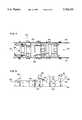
- FIG. 1is a schematic illustration of an exemplary thermal printer constructed in accordance with the principles of the present invention, arrows have been provided showing the card input path of the printer;
- FIG. 2is a schematic illustration of the thermal printer of FIG. 1, arrows have been provided showing the card output path of the printer;
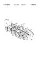
- FIG. 3is a perspective view of an exemplary unitary chassis defining a card path constructed in accordance with the principles of the present invention
- FIG. 4is a top view of the chassis of FIG. 3;
- FIG. 5is a side view of the chassis of FIG. 3;
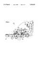
- FIG. 6shows a printer incorporating the chassis of FIGS. 3-5.
- FIGS. 1 and 2schematically illustrate a thermal printer 20 constructed in accordance with the principles of the present invention.
- the thermal printer 20includes a housing 22 having an input/output end 24 including an input station 26 for feeding cards into the printer and an output station 28 for receiving printed cards from a printer.
- the input/output end 24 of the printer 20will be described as being located at a front end 25 of the housing 22 while the opposite end of the housing 22 will be referred to as a back end 27.
- the input station 26is shown supporting a stack of cards 30 awaiting to be fed into the printer 20. It is preferred for the input and output stations 26 and 28 to comprise hoppers that are readily removable from the input/output end 24 of the housing 22.
- the thermal printer 20also includes a print module 32 positioned within the housing 22.
- the print module 32preferably includes a thermal print head that provides a plurality of resistive dot elements.
- the dot elementsare used to selectively heat a transfer ribbon which transfers a thermally reactive dye or ink from a carrier ribbon to a card positioned adjacent to the print head.
- Representative print head manufacturersinclude Toshiba International Corporation, Kyocera Electronics, Inc, Ricoh Company, TDK Corporation, and others.
- the thermal printer 20also includes a printing region 34 positioned adjacent to the print module 32.
- the printing region 34includes a printing platform 36 having a top surface comprising a substantially planar printing surface 38 configured for supporting a card while the card is being printed.
- the printing platform 36defines an opening through which a print roller 40 projects.
- the print roller 40is preferably aligned with the dots of the thermal print head and the rotation of the print roller 40 is preferably coordinated with the printer 32. Consequently, the print roller 40 is constructed and arranged to control the positioning of a card desired to be printed relative to the printer 32.
- the thermal printer 20also includes a stationary diverter ramp 42, a stationary output ramp 44, and an intermediate guide ramp 46.
- the diverter ramp 42, the output ramp 44, and the guide ramp 46cooperate to passively guide cards along an input path (shown in FIG. 1) and along an output path (shown in FIG. 2).
- Cardsare fed through the printer 20 by first and second pick rollers 48 and 50 which are positioned below the input station 26, a first driven roller 52 positioned between the output ramp 44 and the guide ramp 46, a second driven roller 54 positioned between the guide ramp 46 and the printing platform 36, and a third driven roller 56 positioned at the back end of the printing platform 36.
- Corresponding first, second, and third idler rollers 58, 60, and 62are respectively positioned above the first, second, and third driven rollers 52, 54, and 56.
- the diverter ramp 42 of the thermal printer 20is positioned below the input station 26 and includes a front surface 64 that generally faces the input/output 24 of the housing 22, and a back surface 66 that generally faces the back end 27 of the housing 22.
- the front surface 64is constructed and arranged to guide cards from the input station 26 over a top edge 68 of the diverter ramp 42.
- the back surface 66 of the diverter ramp 42is constructed and arranged to divert printed cards to the output station 28.
- the stationary output ramp 44 of the printer 20is positioned between and generally below the diverter ramp 42 and the guide ramp 46.
- the output ramp 44includes an output guide surface 70 that generally faces the back surface 66 of the diverter ramp 42.
- the output ramp 44is constructed and arranged to guide cards that are diverted by the back surface 66 of the diverter ramp 42 into the output station 28.
- the intermediate guide ramp 46 of the card printing machine 20is positioned between the first and second driven rollers 52 and 54.
- the top of the guide ramp 46defines a primary guide surface 72 for guiding cards between the first and second driven rollers 52 and 54.
- the intermediate guide ramp 46also includes a top front edge 74 positioned adjacent to the first driven roller 52 and a top back edge 76 positioned adjacent to the second driven roller 54. The back portion of the intermediate guide ramp 46 tapers upward to guide cards into the nip between the second drive roller 54 and the second idler roller 60.
- the top edge 68 of the diverter ramp 42, the primary guide surface 72 of the intermediate guide ramp 46, and the top portions of the first pick roller 48, the second pick roller 50, and the first driven roller 52are all aligned substantially along a single input path plane.
- the printing surface 38 of the printing platform 36, the top front edge 74 of the intermediate guide ramp 46, and the upper portions of the first, second, and third driven rollers 52, 54, and 56are aligned generally along a single output path plane that intersects with the back surface 66 of the stationary diverter ramp 42.
- the above-described arrangementinsures minimal bending of the card as it is fed through the thermal printer 20.
- a cardis picked from the bottom of the card stack 30 by the pick rollers 48 and 50 and fed over the top edge 68 of the stationary diverter ramp 42.
- the front surface 64 of the diverter ramp 42is angled such that if the leading edge of the card contacts the front surface 64, the card is guided over the top edge 68 of the diverter ramp 42.
- the pick rollers 48 and 50feed the card past the top edge 68 of the diverter ramp 42 and into the nip defined between the first driven roller 52 and the first idler roller 58.
- the first driven roller 52feeds the card toward the intermediate guide ramp 46.
- the cardremains oriented along the input path plane defined by the top edge 68 of the diverter ramp 42 and the guide surface 72 of the intermediate guide ramp 46 until the trailing edge of the card passes the top edge 68 of the diverter ramp 42 and the leading edge of the card contacts the tapered portion at the back end of the intermediate guide ramp 46.
- the first driven roller 52 and the tapered back end of the intermediate guide ramp 46cooperate to move the card to a plane substantially parallel to the printing surface 38 of the printing platform 36.
- the leading edge of the cardis then fed into the nip formed between the second driven roller 54 and the second idler roller 60.
- the second driven roller 54feeds the card into the printing region 34 where the card is printed by the print module 32.
- the first, second, and third driven rollers 52, 54, and 56reverse directions and move the card from the back end 27 of the housing 22 toward the front end 25 of the housing 22.
- the cardtravels along the output path plane aligned generally along the printing surface 38 of the printing platform 36 and the top front edge 74 of the intermediate guide ramp 46.
- the cardremains oriented on the output path plane of the printing surface 38 until the leading edge of the card engages the back surface 66 of the stationary diverter ramp 42.
- the cardUpon engagement with the back surface 66 of the diverter ramp 42, the card is directed downward toward the stationary output ramp 44.
- the output guide surface 70 of the stationary output ramp 44guides the card downward to the output station 28.
- the cardexperiences minimal bending. Specifically, during input, the card is aligned at an angle with respect to the printing path until its trailing edge passes the diverter ramp 42. After passing the diverter ramp 42, the card straightens out along the print path. During output, the card follows the straight print path until it is diverted by the diverter 42.
- the substantially planar paths followed by the cardminimize card bending and assist in maintaining contact between the card and the driven rollers 52, 54, and 56.
- FIGS. 3-5illustrate a one-piece printer chassis 120 constructed in accordance with the principles of the present invention.
- the printer chassis 120has a first end 122 positioned opposite from a second end 124. Opposing sidewalls 126 extend between the first and second ends 122 and 124. Similar to the schematic embodiment disclosed in FIGS. 1 and 2, the printer chassis 120 includes a stationary diverter ramp 42', a stationary output ramp 44', an intermediate guide ramp 46', and a printing platform 36'.
- the chassis 120preferably also includes structure for connecting rollers to the chassis 120.
- a plurality of mounts 128 for limiting lateral movement of the rollersare unitarily formed with the chassis 120.
- the sidewalls 126define a plurality of openings 130 in which the shafts of driven rollers can be journaled.
- the chassis 120includes a plurality of elongated vertical slots 132 in which the shafts of idler rollers can be journaled. It will be appreciated that the chassis is also equipped with a plurality of roller openings defined adjacent to at least some of the openings 130 in the sidewalls 126 for allowing the different rollers journaled in the sidewalls 126 to project into the card path defined by the chassis 120.
- the chassis 120further includes structure for mounting printing equipment on the chassis 120.
- the second end 124 of the chassisincludes a pair of arms 134 having apertures for pivotally connecting a print module to the chassis 120.
- the chassis 120also includes elevated support members 136 having slots configured for rotatably mounting reels on which a ribbon containing transfer ink can be wound.
- the chassis 120includes alignment slots 140 and opposing first and second alignment surfaces 142 and 144 for aligning a print head at a particular location on the chassis 120.
- the alignment slots 140are located at the sidewalls 126 of the chassis 120 adjacent the printing platform 36'.
- FIG. 6shows a thermal printer 150 incorporating the chassis 120.
- the printer 150includes a pivot arm 152 pivotally mounted on the mounting arms 134 of the chassis 120.
- a print moduleincluding a carriage 154 containing a thermal print head 156 is mounted on the arm 152.
- the carriage 154includes two sets of first and second alignment pins 158 and 160 (one set of alignment pins is shown) which project laterally outward from opposite sides of the carriage.
- the print head 156is positioned at a predetermined location relative to the first and second sets of mounting pins 158 and 160. The positioning of the print head 156 can be controlled by sliding the print head along adjustment slots 162 defined by the carriage 154.
- the pivot arm 152 of the thermal printer 150is pivotally movable between a non-printing position and a printing position.
- the first alignment pins 158are positioned within the slots 140 of the chassis 120 to control the vertical orientation of the print head 156.
- the first alignment pins 158are preferably biased against the second alignment surfaces 144 of the chassis 120, while the second alignment pins 160 are preferably biased against the first alignment surfaces 142 of the chassis 120. In this manner, the opposing alignment surfaces 142 and 144 control the alignment of the print head 156 relative to the printing platform 36'.
- the thermal printer 150also includes ink or dye ribbon reels 164 mounted in the elevated members 136 of the chassis 120. Additionally, a print roller 166 is shown mounted directly below the alignment pins 158 and 160 of the print head carriage 154.
- cardsincludes substrates of various sizes made of various materials such as plastic, paper coated with plastic, plastic/paper composites, and any other materials and composites thereof suitable for thermal printing.
- exemplary systemsinclude optional magnetic stripe encoding and smart card initializing stations for imparting information to magnetic stripes or integrated circuits associated with cards being printed.
Landscapes
- Engineering & Computer Science (AREA)
- Mechanical Engineering (AREA)
- Electronic Switches (AREA)
- Handling Of Cut Paper (AREA)
- Organic Low-Molecular-Weight Compounds And Preparation Thereof (AREA)
- Accessory Devices And Overall Control Thereof (AREA)
- Heat Sensitive Colour Forming Recording (AREA)
- Thermal Transfer Or Thermal Recording In General (AREA)
Abstract
Description
Claims (11)
Priority Applications (9)
| Application Number | Priority Date | Filing Date | Title |
|---|---|---|---|
| US08/797,873US5762431A (en) | 1997-02-10 | 1997-02-10 | Thermal printer and method for using |
| DE69825756TDE69825756T2 (en) | 1997-02-10 | 1998-02-06 | THERMAL PRINTERS AND METHOD FOR ITS USE |
| CA002279177ACA2279177C (en) | 1997-02-10 | 1998-02-06 | Thermal printer and method for using |
| JP53505998AJP4005644B2 (en) | 1997-02-10 | 1998-02-06 | Thermal printer and how to use it |
| EP98906369AEP1007368B1 (en) | 1997-02-10 | 1998-02-06 | Thermal printer and method for using |
| AU61609/98AAU6160998A (en) | 1997-02-10 | 1998-02-06 | Thermal printer and method for using |
| AT98906369TATE273798T1 (en) | 1997-02-10 | 1998-02-06 | THERMAL PRINTER AND METHOD OF USE THEREOF |
| CN98802387ACN1089066C (en) | 1997-02-10 | 1998-02-06 | Thermal printer and how to use it |
| PCT/US1998/002732WO1998034790A1 (en) | 1997-02-10 | 1998-02-06 | Thermal printer and method for using |
Applications Claiming Priority (1)
| Application Number | Priority Date | Filing Date | Title |
|---|---|---|---|
| US08/797,873US5762431A (en) | 1997-02-10 | 1997-02-10 | Thermal printer and method for using |
Publications (1)
| Publication Number | Publication Date |
|---|---|
| US5762431Atrue US5762431A (en) | 1998-06-09 |
Family
ID=25172002
Family Applications (1)
| Application Number | Title | Priority Date | Filing Date |
|---|---|---|---|
| US08/797,873Expired - LifetimeUS5762431A (en) | 1997-02-10 | 1997-02-10 | Thermal printer and method for using |
Country Status (9)
| Country | Link |
|---|---|
| US (1) | US5762431A (en) |
| EP (1) | EP1007368B1 (en) |
| JP (1) | JP4005644B2 (en) |
| CN (1) | CN1089066C (en) |
| AT (1) | ATE273798T1 (en) |
| AU (1) | AU6160998A (en) |
| CA (1) | CA2279177C (en) |
| DE (1) | DE69825756T2 (en) |
| WO (1) | WO1998034790A1 (en) |
Cited By (21)
| Publication number | Priority date | Publication date | Assignee | Title |
|---|---|---|---|---|
| US6042109A (en)* | 1997-08-29 | 2000-03-28 | Hewlett-Packard Company | Sheet feeding device with compact media path for paper-based and photographic media |
| US6215797B1 (en) | 1998-08-19 | 2001-04-10 | Path 1 Technologies, Inc. | Methods and apparatus for providing quality of service guarantees in computer networks |
| US6530633B2 (en)* | 2000-05-15 | 2003-03-11 | Seiko Epson Corporation | Card printing method and apparatus |
| US6554512B2 (en)* | 2001-04-26 | 2003-04-29 | Zih Corp. | Printer for printing deformable flat supports and its loader |
| US20030152409A1 (en)* | 1999-01-25 | 2003-08-14 | Pribula Martin A. | Card Cartridge |
| US20030188648A1 (en)* | 2002-04-08 | 2003-10-09 | Ecrm Inc. | System and method for sheet transporting using dual capstan rollers |
| US20030227420A1 (en)* | 2002-06-05 | 2003-12-11 | Andrew Corporation | Integrated aperture and calibration feed for adaptive beamforming systems |
| US20040022572A1 (en)* | 2002-07-31 | 2004-02-05 | Datacard Corporation | Supply items for printers and the like, and method of loading supply items |
| US20050104281A1 (en)* | 2003-11-17 | 2005-05-19 | Datacard Corporation | Plastic card reorienting mechanism and interchangeable input hopper |
| US20060175395A1 (en)* | 2005-02-04 | 2006-08-10 | Paulson Arthur J | Desktop card processor |
| US20080219745A1 (en)* | 2007-03-06 | 2008-09-11 | Datacard Corporation | Indent printing apparatus |
| EP2110259A2 (en) | 2001-12-21 | 2009-10-21 | Datacard Corporation | Radio frequency identification tags on consumable items used in printers and related equipment |
| US20100090395A1 (en)* | 2008-10-10 | 2010-04-15 | Lasermax Roll Systems, Inc. | System and method for rotating sheets |
| US20110247509A1 (en)* | 2010-04-08 | 2011-10-13 | Tit Eng Co., Ltd. | Id card printer with manual card slot |
| US8382092B2 (en) | 2009-09-18 | 2013-02-26 | Hid Global Corporation | Dual hopper assembly |
| US8730283B2 (en) | 2009-09-18 | 2014-05-20 | Assa Abloy Ab | Credential substrate feeding in a credential processing device |
| US9195923B2 (en) | 2007-01-25 | 2015-11-24 | Entrust Datacard Corporation | In-line document puncher/voider in a document personalization machine |
| US20180144146A1 (en)* | 2016-11-23 | 2018-05-24 | Entrust Datacard Corporation | Printer identity and security |
| US10384883B2 (en) | 2012-02-23 | 2019-08-20 | Entrust Datacard Corporation | Card reorienting mechanism and methods utilizing same |
| US20200079126A1 (en)* | 2018-09-11 | 2020-03-12 | Frama Ag | Method for franking packages individually supplied from a stack by a franking machine |
| KR20210043737A (en)* | 2018-09-11 | 2021-04-21 | 인트러스트 코포레이션 | Print head guard |
Families Citing this family (2)
| Publication number | Priority date | Publication date | Assignee | Title |
|---|---|---|---|---|
| JP4994829B2 (en)* | 2006-12-28 | 2012-08-08 | ニスカ株式会社 | Card recorder |
| CN105730027B (en)* | 2016-03-03 | 2018-01-26 | 深圳市速普特智能科技有限公司 | One kind disengaging card structure |
Citations (7)
| Publication number | Priority date | Publication date | Assignee | Title |
|---|---|---|---|---|
| US4189135A (en)* | 1976-09-22 | 1980-02-19 | Ing. C. Olivetti & Co., S.P.A. | Sheet feeder for a writing system |
| US4594597A (en)* | 1985-08-13 | 1986-06-10 | Sanders Associates, Inc. | Thermal printer |
| US4619197A (en)* | 1984-06-29 | 1986-10-28 | Electronique Serge Dassault | Apparatus for printing and inspecting card tickets |
| US4932798A (en)* | 1986-09-22 | 1990-06-12 | Siemens Aktiengesellschaft | Apparatus for recording image information on both sides of recording sheets |
| US5296874A (en)* | 1990-10-19 | 1994-03-22 | Fuji Photo Film Co., Ltd. | Thermal printer |
| US5547183A (en)* | 1991-08-30 | 1996-08-20 | Asahi Kogaku Kogyo Kabushiki Kaisha | Imaging device |
| US5645362A (en)* | 1989-05-08 | 1997-07-08 | Mitsubishi Denki Kabushiki Kaisha | Printer |
Family Cites Families (4)
| Publication number | Priority date | Publication date | Assignee | Title |
|---|---|---|---|---|
| JPS60110482A (en)* | 1983-11-22 | 1985-06-15 | Toshiba Corp | Image forming apparatus |
| JPH01281970A (en)* | 1988-05-10 | 1989-11-13 | Mitsubishi Electric Corp | Printing device |
| JPH0642853Y2 (en)* | 1988-10-28 | 1994-11-09 | 新王子製紙株式会社 | printer |
| JPH0473175A (en)* | 1990-07-13 | 1992-03-09 | Tokyo Electric Co Ltd | Printer |
- 1997
- 1997-02-10USUS08/797,873patent/US5762431A/ennot_activeExpired - Lifetime
- 1998
- 1998-02-06CACA002279177Apatent/CA2279177C/ennot_activeExpired - Fee Related
- 1998-02-06DEDE69825756Tpatent/DE69825756T2/ennot_activeExpired - Lifetime
- 1998-02-06JPJP53505998Apatent/JP4005644B2/ennot_activeExpired - Fee Related
- 1998-02-06CNCN98802387Apatent/CN1089066C/ennot_activeExpired - Fee Related
- 1998-02-06AUAU61609/98Apatent/AU6160998A/ennot_activeAbandoned
- 1998-02-06WOPCT/US1998/002732patent/WO1998034790A1/enactiveIP Right Grant
- 1998-02-06ATAT98906369Tpatent/ATE273798T1/ennot_activeIP Right Cessation
- 1998-02-06EPEP98906369Apatent/EP1007368B1/ennot_activeExpired - Lifetime
Patent Citations (7)
| Publication number | Priority date | Publication date | Assignee | Title |
|---|---|---|---|---|
| US4189135A (en)* | 1976-09-22 | 1980-02-19 | Ing. C. Olivetti & Co., S.P.A. | Sheet feeder for a writing system |
| US4619197A (en)* | 1984-06-29 | 1986-10-28 | Electronique Serge Dassault | Apparatus for printing and inspecting card tickets |
| US4594597A (en)* | 1985-08-13 | 1986-06-10 | Sanders Associates, Inc. | Thermal printer |
| US4932798A (en)* | 1986-09-22 | 1990-06-12 | Siemens Aktiengesellschaft | Apparatus for recording image information on both sides of recording sheets |
| US5645362A (en)* | 1989-05-08 | 1997-07-08 | Mitsubishi Denki Kabushiki Kaisha | Printer |
| US5296874A (en)* | 1990-10-19 | 1994-03-22 | Fuji Photo Film Co., Ltd. | Thermal printer |
| US5547183A (en)* | 1991-08-30 | 1996-08-20 | Asahi Kogaku Kogyo Kabushiki Kaisha | Imaging device |
Cited By (42)
| Publication number | Priority date | Publication date | Assignee | Title |
|---|---|---|---|---|
| US6042109A (en)* | 1997-08-29 | 2000-03-28 | Hewlett-Packard Company | Sheet feeding device with compact media path for paper-based and photographic media |
| US6751231B2 (en) | 1998-08-19 | 2004-06-15 | Path 1 Network Technologies Inc. | Methods and apparatus for providing quality of service guarantees in computer networks |
| US6215797B1 (en) | 1998-08-19 | 2001-04-10 | Path 1 Technologies, Inc. | Methods and apparatus for providing quality of service guarantees in computer networks |
| US20030152409A1 (en)* | 1999-01-25 | 2003-08-14 | Pribula Martin A. | Card Cartridge |
| US6932527B2 (en)* | 1999-01-25 | 2005-08-23 | Fargo Electronics, Inc. | Card cartridge |
| US6530633B2 (en)* | 2000-05-15 | 2003-03-11 | Seiko Epson Corporation | Card printing method and apparatus |
| US20040246328A1 (en)* | 2001-04-26 | 2004-12-09 | Gaetan Heno | Printer for printing deformable planar print media and its loader |
| US6554512B2 (en)* | 2001-04-26 | 2003-04-29 | Zih Corp. | Printer for printing deformable flat supports and its loader |
| EP2236306A1 (en) | 2001-12-21 | 2010-10-06 | Datacard Corporation | Radio frequency identification tag |
| EP2241446A1 (en) | 2001-12-21 | 2010-10-20 | Datacard Corporation | Radio frequency identification tag |
| EP2110259A2 (en) | 2001-12-21 | 2009-10-21 | Datacard Corporation | Radio frequency identification tags on consumable items used in printers and related equipment |
| US7066463B2 (en)* | 2002-04-08 | 2006-06-27 | Ecrm Incorporated | System and method for sheet transporting using dual capstan rollers |
| US20030188648A1 (en)* | 2002-04-08 | 2003-10-09 | Ecrm Inc. | System and method for sheet transporting using dual capstan rollers |
| US20050189692A1 (en)* | 2002-04-08 | 2005-09-01 | Ecrm Inc. | System and method for sheet transporting using dual capstan rollers |
| US7040617B2 (en)* | 2002-04-08 | 2006-05-09 | Ecrm Incorporated | System and method for sheet transporting using dual capstan rollers |
| US20030227420A1 (en)* | 2002-06-05 | 2003-12-11 | Andrew Corporation | Integrated aperture and calibration feed for adaptive beamforming systems |
| US6997629B2 (en) | 2002-07-31 | 2006-02-14 | Datacard Corporation | Supply items for printers and the like, and method of loading supply items |
| US20040022572A1 (en)* | 2002-07-31 | 2004-02-05 | Datacard Corporation | Supply items for printers and the like, and method of loading supply items |
| US7398972B2 (en) | 2003-11-17 | 2008-07-15 | Datacard Corporation | Plastic card reorienting mechanism and interchangeable input hopper |
| US20090121409A1 (en)* | 2003-11-17 | 2009-05-14 | Datacard Corporation | Plastic card reorienting mechanism and interchangeable input hopper |
| US20050104281A1 (en)* | 2003-11-17 | 2005-05-19 | Datacard Corporation | Plastic card reorienting mechanism and interchangeable input hopper |
| US20060175395A1 (en)* | 2005-02-04 | 2006-08-10 | Paulson Arthur J | Desktop card processor |
| US20080106585A1 (en)* | 2005-02-04 | 2008-05-08 | Datacard Corporation | Desktop card processor |
| US7434728B2 (en) | 2005-02-04 | 2008-10-14 | Datacard Corporation | Desktop card processor |
| US8042735B2 (en) | 2005-02-04 | 2011-10-25 | Datacard Corporation | Desktop card processor |
| US9195923B2 (en) | 2007-01-25 | 2015-11-24 | Entrust Datacard Corporation | In-line document puncher/voider in a document personalization machine |
| WO2008109282A1 (en) | 2007-03-06 | 2008-09-12 | Datacard Corporation | Indent printing apparatus |
| US7866904B2 (en) | 2007-03-06 | 2011-01-11 | Datacard Corporation | Desktop card printer with indent printing apparatus and method of printing |
| US20080219745A1 (en)* | 2007-03-06 | 2008-09-11 | Datacard Corporation | Indent printing apparatus |
| EP2933102A1 (en) | 2007-03-06 | 2015-10-21 | Entrust Datacard Corporation | Indent printing apparatus |
| US20100090395A1 (en)* | 2008-10-10 | 2010-04-15 | Lasermax Roll Systems, Inc. | System and method for rotating sheets |
| US8061709B2 (en)* | 2008-10-10 | 2011-11-22 | Lasermax Roll Systems, Inc. | System and method for rotating sheets |
| US8430400B2 (en) | 2008-10-10 | 2013-04-30 | Lasermax Roll Systems, Inc. | System and method for rotating sheets |
| US8730283B2 (en) | 2009-09-18 | 2014-05-20 | Assa Abloy Ab | Credential substrate feeding in a credential processing device |
| US8382092B2 (en) | 2009-09-18 | 2013-02-26 | Hid Global Corporation | Dual hopper assembly |
| US20110247509A1 (en)* | 2010-04-08 | 2011-10-13 | Tit Eng Co., Ltd. | Id card printer with manual card slot |
| US10384883B2 (en) | 2012-02-23 | 2019-08-20 | Entrust Datacard Corporation | Card reorienting mechanism and methods utilizing same |
| US20180144146A1 (en)* | 2016-11-23 | 2018-05-24 | Entrust Datacard Corporation | Printer identity and security |
| US10872161B2 (en)* | 2016-11-23 | 2020-12-22 | Entrust Corporation | Printer identity and security |
| US20200079126A1 (en)* | 2018-09-11 | 2020-03-12 | Frama Ag | Method for franking packages individually supplied from a stack by a franking machine |
| KR20210043737A (en)* | 2018-09-11 | 2021-04-21 | 인트러스트 코포레이션 | Print head guard |
| US11420840B2 (en)* | 2018-09-11 | 2022-08-23 | Frama Ag | Method for franking packages individually supplied from a stack by a franking machine |
Also Published As
| Publication number | Publication date |
|---|---|
| ATE273798T1 (en) | 2004-09-15 |
| AU6160998A (en) | 1998-08-26 |
| EP1007368A1 (en) | 2000-06-14 |
| DE69825756D1 (en) | 2004-09-23 |
| EP1007368A4 (en) | 2000-06-14 |
| JP2001512378A (en) | 2001-08-21 |
| CN1246827A (en) | 2000-03-08 |
| CA2279177A1 (en) | 1998-08-13 |
| WO1998034790A1 (en) | 1998-08-13 |
| CN1089066C (en) | 2002-08-14 |
| DE69825756T2 (en) | 2005-08-25 |
| JP4005644B2 (en) | 2007-11-07 |
| CA2279177C (en) | 2007-09-18 |
| EP1007368B1 (en) | 2004-08-18 |
Similar Documents
| Publication | Publication Date | Title |
|---|---|---|
| US5762431A (en) | Thermal printer and method for using | |
| US7717632B2 (en) | Card printer printhead mounting | |
| KR100768730B1 (en) | Printer with Intermediate Transfer Film | |
| US5913510A (en) | Recording apparatus | |
| US6581922B2 (en) | Sheet processing apparatus above image forming means and image forming apparatus | |
| JPS61145056A (en) | Conveyor for flexible band | |
| EP0983861B1 (en) | Printer | |
| US6367910B1 (en) | Multiple inline print head with servo driven mechanical interlocked print head assemblies | |
| US6036381A (en) | Book printer including support for accommodating bound portion | |
| US5129751A (en) | Replaceable structural unit for a printer | |
| US6953192B2 (en) | Paper delivery device in printer and printer using the same | |
| US6293650B1 (en) | In-line printer with manual positionable mechanically interlocked multiple print head assemblies | |
| US20070292189A1 (en) | Multi-passing apparatus and image forming apparatus having the same | |
| US20010010775A1 (en) | Platen and printing apparatus | |
| US6869175B2 (en) | Recording apparatus | |
| JPH01502175A (en) | Card removal device | |
| EP1652681B1 (en) | Image recording apparatus and sheet material transporting apparatus | |
| GB2033304A (en) | A multiple-head printer | |
| KR0164543B1 (en) | Duplex printing apparatus and method for inkjet printer | |
| JP4057142B2 (en) | Printer having movable paper guide plate mechanism and control method thereof | |
| JPH0844934A (en) | Device for printing bankbook and method thereof | |
| JP2001301257A (en) | Card transfer device | |
| JP2001301256A (en) | Card transfer device in card printer | |
| WO2002060693A1 (en) | Multiple in-line print-head assemblies | |
| JPH0636849U (en) | Printer bail arm mechanism |
Legal Events
| Date | Code | Title | Description |
|---|---|---|---|
| AS | Assignment | Owner name:DATACARD CORPORATION, MINNESOTA Free format text:ASSIGNMENT OF ASSIGNORS INTEREST;ASSIGNORS:PAWELKA, GERHARD E.F.;AMBROSINA, JESSE ERIN;REEL/FRAME:008624/0168 Effective date:19970701 | |
| STCF | Information on status: patent grant | Free format text:PATENTED CASE | |
| FPAY | Fee payment | Year of fee payment:4 | |
| FPAY | Fee payment | Year of fee payment:8 | |
| FPAY | Fee payment | Year of fee payment:12 | |
| AS | Assignment | Owner name:BMO HARRIS BANK N.A., AS COLLATERAL AGENT, ILLINOI Free format text:SECURITY AGREEMENT;ASSIGNOR:DATACARD CORPORATION;REEL/FRAME:032087/0350 Effective date:20131231 | |
| AS | Assignment | Owner name:ENTRUST DATACARD CORPORATION, MINNESOTA Free format text:CHANGE OF NAME;ASSIGNOR:DATACARD CORPORATION;REEL/FRAME:035108/0995 Effective date:20141112 | |
| AS | Assignment | Owner name:ENTRUST DATACARD CORPORATION, MINNESOTA Free format text:RELEASE;ASSIGNOR:BMO HARRIS BANK N.A., AS AGENT;REEL/FRAME:045950/0240 Effective date:20180413 |