US5761615A - Wide band zero if quadrature demodulator using a intermediate frequency and a single local oscillator - Google Patents
Wide band zero if quadrature demodulator using a intermediate frequency and a single local oscillatorDownload PDFInfo
- Publication number
- US5761615A US5761615AUS08/456,985US45698595AUS5761615AUS 5761615 AUS5761615 AUS 5761615AUS 45698595 AUS45698595 AUS 45698595AUS 5761615 AUS5761615 AUS 5761615A
- Authority
- US
- United States
- Prior art keywords
- mixer
- frequency
- signal
- low power
- selective call
- Prior art date
- Legal status (The legal status is an assumption and is not a legal conclusion. Google has not performed a legal analysis and makes no representation as to the accuracy of the status listed.)
- Expired - Lifetime
Links
Images


Classifications
- H—ELECTRICITY
- H04—ELECTRIC COMMUNICATION TECHNIQUE
- H04B—TRANSMISSION
- H04B1/00—Details of transmission systems, not covered by a single one of groups H04B3/00 - H04B13/00; Details of transmission systems not characterised by the medium used for transmission
- H04B1/06—Receivers
- H04B1/16—Circuits
- H—ELECTRICITY
- H03—ELECTRONIC CIRCUITRY
- H03D—DEMODULATION OR TRANSFERENCE OF MODULATION FROM ONE CARRIER TO ANOTHER
- H03D3/00—Demodulation of angle-, frequency- or phase- modulated oscillations
- H03D3/007—Demodulation of angle-, frequency- or phase- modulated oscillations by converting the oscillations into two quadrature related signals
- H—ELECTRICITY
- H04—ELECTRIC COMMUNICATION TECHNIQUE
- H04B—TRANSMISSION
- H04B1/00—Details of transmission systems, not covered by a single one of groups H04B3/00 - H04B13/00; Details of transmission systems not characterised by the medium used for transmission
- H04B1/06—Receivers
- H04B1/16—Circuits
- H04B1/30—Circuits for homodyne or synchrodyne receivers
Definitions
- This inventionrelates generally to direct conversion receivers, and more specifically to low power direct conversion paging receivers.
- direct conversion receiversIn portable battery operated products such as a selective call receiver, direct conversion receivers, having few stages, offer many advantages when used in low power personal paging receivers. The reduction in the number of stages contributes to long battery life and a small physical package. Although these advantages are important, the difficulty evolved in the design of direct conversion receiver and the reduced performance of a direct conversion receiver when compared with other receivers such as the super heterodyne receivers sometimes outweigh the advantages.
- Direct conversion receiversrequire the generation of a local oscillator on a frequency equal to the desired receiver carrier frequency.
- This relatively strong local oscillator signalmust be well isolated from the antenna and the input of the receiver. Otherwise, leakage of the local oscillator signal into the receiver's signal frequency path may cause overload of sensitive stages in the receiver and to the generation of a strong D.C. component in the output of a detector. This condition results in poor sensitivity and degraded spurious signal rejection.
- the presence of a D.C. componentmust also be rejected in the baseband amplifier, further complicating the design of the baseband amplifiers.
- the degree of isolation needed for proper RF operationis difficult to obtain in large non-portable receivers, and even more difficult obtain in a very small personal receiver.
- the quadrature detectors generally used in direct conversion receiversrequire a local oscillator to have two outputs comprising an in phase and a quadrature phase output signal. To achieve good spurious signal rejection, the quadrature phase and amplitude relationships of the two signals must be very accurately matched. Prior art methods of obtaining the accuracy required of these quadrature signals are not compatible with the modern objectives of a low part count and low power consumption design needed for price and specification competitive personal battery powered equipment.
- a low power zero-IF selective call receiverthat solves several of the problems associated with a direct conversion receiver, while maintaining the advantages of utilizing the least number of conversion stages, resulting in low power consumption and efficient operation.
- a first mixer and a local oscillatoroperate to convert the received carrier signal to an intermediate signal.
- the same local oscillatoris also used by a digital phase shifter/divider to derive two quadrature signals that are used by a pair of second mixers to demodulate the intermediate signal into two quadrature baseband signals.
- FIG. 1is a detailed block diagram, showing the first mixer, the single local oscillator, the wideband phase shifter/divider, and the second and the third mixer, configured in accordance with the invention.
- FIG. 2is a timing diagram showing the relationship of the signals in the digital phase shifter/divider.
- FIG. 3is a detailed block diagram showing the replacement of some of the unbalanced elements and signal lines with balanced element and balanced signal lines.
- FIG. 4is a timing diagram showing the relationship of the balanced signals in the digital phase shifter/divider.
- FIG. 5is a selective call receiver incorporating the elements of FIG. 3.
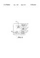
- FIG. 6shows an exemplary implementation of the circuit components shown in FIG. 1, FIG. 3, and FIG. 5 comprising the first mixer, the local oscillator, the wideband phase shifter/divider, and the second and the third mixer, in a single integrated circuit.
- the inventionovercomes many of the disadvantages associated with a direct conversion receiver.
- the inventionovercomes these disadvantages by incorporating a first mixer 104 that converts a received carrier signal 102 to an intermediate signal 108, without incurring the cost and power consumption penalty of adding a second crystal oscillator.
- the inventionaccomplishes this by designing the receiver in such a way that the frequency of the received carrier signal 102 (f c ) the frequency of a local oscillator 106, (f LO ), the frequency of the intermediate signal 108, (f IF ), and the frequency of an in phase injection signal 122 and a quadrature phase injection signal 124, has a specific relationship.
- the specific relationshipcan be shown by referring to FIG. 1.
- the received carrier signal 102 and a local oscillator signal 110 from the local oscillator 106is coupled to the first mixer 104.
- the first mixer 104produces the intermediate signal 108 having a frequency f IF .
- the intermediate signal 108is coupled to a second mixer 112 and a third mixer 114 (a pair of mixers).
- the local oscillator signal 110is also coupled to the digital phase shifter/divider 116.
- the digital phase shifter/divider 116comprises a first D type latch 120 and a second D type latch 118 configured as a Johnson counter.
- the signals associated with the Johnson counterare shown in FIG. 2.
- the local oscillator signal 110is shown in FIG. 2 as a square wave for convenience as local oscillator signal waveform 202.
- the operation of the Johnson counteris well known to those familiar with the art of digital circuit design.
- the frequency of the in phase injection signal 122 and the frequency of the quadrature phase injection signal 124, (f INJ )are equal to f LO /N.
- the in phase injection signal 122is coupled to the second mixer 112 and the quadrature phase injection signal 124 is coupled to the third mixer 114.
- the second mixer 112 and the third mixer 114produce a plurality of signals.
- the signals of interestare an in phase baseband signal 126 and a quadrature phase baseband signal 128 produced by the second mixer 112 and the third mixer respectively, and being converted quadrature components of the information modulated on the received carrier signal 102.
- F INJmust be essentially equal to f IF . It then follows that if
- the intermediate signal 108is not fixed, as in a conventional receiver with a mixer and a fixed intermediate frequency amplifier, but changes as the received carrier signal 102 changes.
- the frequency of the intermediate signal 108 changing in this manneris called a walking intermediate frequency signal.
- FIG. 3shows the circuit of FIG. 1 that is an enhancement to reduce radiation and undesirable coupling of the in phase injection signal 122 and the quadrature phase injection signal 124, where in the digital phase shifter/divider 116 has been replaced with a digital phase shifter/divider having balanced outputs 302, the conductor carrying the in phase injection signal 122 is replaced with balanced conductors, carrying a balanced in phase injection signals 304, the conductor carrying the quadrature phase injection signal 124 is replaced with balanced conductors, carrying a balanced quadrature phase injection signals 306, the second mixer 112 is replaced with a second mixer having balanced inputs 310, and the third mixer 114 is replaced with a third mixer having balanced inputs 308.
- FIG. 4shows the signal waveforms that are present in the enhanced circuit.
- the balanced in phase injection signal 304is now represented by a pair of waveforms, a balanced 0° phase injection signal waveform 402 and a balanced 180° phase injection signal waveform 404
- the balanced quadrature phase injection signal 308is now represented by a pair of waveforms, a balanced 90° phase injection signal waveform 406 and a balanced 270° phase injection signal waveform 408. Notice how the two waveforms in each pair complement each other.
- Each pairs of signalsare routed together such that any electromagnetic field from one conductor that causes undesirable coupling to another circuit is canceled by the electromagnetic field from the other conductor.
- the first mixer 104, the second mixer 112, the third mixer 114, the second mixer having balanced inputs 310 and the third mixer having balanced inputs 308could comprise, but not limited to one of the following: a non-linear semiconductor mixer, a switching mixer, or a Gilbert cell.
- the local oscillator 106can be a quartz crystal controlled oscillator or a frequency synthesizer 508 as shown in FIG. 5, utilizing digital logic and phase lock loop technology. It can be appreciated that there are many frequency generation techniques that are suitable for this application. such as a discrete crystal controlled single frequency oscillator, frequency synthesized crystal controlled oscillator 508, or a frequency synthesized resonator controlled oscillator.
- the digital phase shifter/divider 116 and the digital phase shifter/divider with balanced outputs 302could comprise but not limited to one of the following: complementary metal oxide semiconductor logic or emitter coupled logic. Moreover, in the preferred embodiment, all circuitry is designed with no more than a single diode drop between the positive and negative potentials, thus yielding circuits that are fully functional at one volt D.C. or less.
- a selective call paging receiveris shown in FIG. 5 that incorporates a wideband phase shifter/divider demodulator 506 of FIG. 3.
- the local oscillator 106has been replaced with a frequency synthesizer 506 providing the local oscillator signal 110.
- a carrier waveis intercepted by an antenna 502 and coupled to RF amplifier 504.
- the output of the RF amplifier 504provides the received carrier signal 102 for the wide band phase shifter/divider demodulator 506.
- the in phase base band signal 126 and a quadrature phase base band signal 128 from the wide band phase shifter/divider demodulator 506is coupled to a decoder 512.
- the decoder 512provides the signal processing appropriate for the type of signal and modulation used.
- the decoder 512is coupled to a controller 514.
- the controller 514is coupled to the frequency synthesizer 508, a code plug 510 and an user interface 516.
- the controller 514provides the basic control of the various functions of the selective call paging receiver and generally consist of a microprocessor, memory and necessary input output devices.
- the code plug 510stores the unique identification information necessary for the controller to implement the selective call feature.
- the user interface 516provides the user with an audio, visual or mechanical signal indicating the reception of information and may also include a display and push buttons for the user to inter commands to control the receiver.
- the local oscillator 106, the first mixer 104, the second mixer having balanced inputs 310 and the third mixer having balanced inputs 308 and the digital phase shifter/divider with balanced outputs 302would be integrated into a single integrated circuit.
- This integrated circuitcould be further enhanced by incorporating the frequency synthesizer 508 shown in FIG. 5.
- FIG. 6shows an exemplary implementation of the circuit components shown in FIG. 1, FIG. 3, and FIG. 5 comprising the first mixer, the local oscillator, the wideband phase shifter/divider, and the second and the third mixer, in a single integrated circuit.
Landscapes
- Engineering & Computer Science (AREA)
- Power Engineering (AREA)
- Computer Networks & Wireless Communication (AREA)
- Signal Processing (AREA)
- Superheterodyne Receivers (AREA)
- Mobile Radio Communication Systems (AREA)
- Digital Transmission Methods That Use Modulated Carrier Waves (AREA)
Abstract
Description
This invention relates generally to direct conversion receivers, and more specifically to low power direct conversion paging receivers.
In portable battery operated products such as a selective call receiver, direct conversion receivers, having few stages, offer many advantages when used in low power personal paging receivers. The reduction in the number of stages contributes to long battery life and a small physical package. Although these advantages are important, the difficulty evolved in the design of direct conversion receiver and the reduced performance of a direct conversion receiver when compared with other receivers such as the super heterodyne receivers sometimes outweigh the advantages.
Direct conversion receivers require the generation of a local oscillator on a frequency equal to the desired receiver carrier frequency. This relatively strong local oscillator signal must be well isolated from the antenna and the input of the receiver. Otherwise, leakage of the local oscillator signal into the receiver's signal frequency path may cause overload of sensitive stages in the receiver and to the generation of a strong D.C. component in the output of a detector. This condition results in poor sensitivity and degraded spurious signal rejection. The presence of a D.C. component must also be rejected in the baseband amplifier, further complicating the design of the baseband amplifiers. The degree of isolation needed for proper RF operation is difficult to obtain in large non-portable receivers, and even more difficult obtain in a very small personal receiver.
The quadrature detectors generally used in direct conversion receivers require a local oscillator to have two outputs comprising an in phase and a quadrature phase output signal. To achieve good spurious signal rejection, the quadrature phase and amplitude relationships of the two signals must be very accurately matched. Prior art methods of obtaining the accuracy required of these quadrature signals are not compatible with the modern objectives of a low part count and low power consumption design needed for price and specification competitive personal battery powered equipment.
Conventionally, a quadrature relationship for injection signals was obtained using a passive phase shift network or the like having quadrature outputs. This analog phase shifter generally maintains quadrature over a quite limited bandwidth. Greater bandwidth can be obtained with a greater complexity and increased parts count.
In an attempt to operate over a wider bandwidth, digital phase shifters were designed. However, these digital phase shifters required the local oscillator to operate at some integer multiple of the required injection frequency, generally four times. Consequently, the local oscillator of a low power 930 MHz paging receiver would yield a system operating at 3720 MHz, which would greatly increase the power required by the oscillator and the digital phase shifter.
Accordingly, what is needed is a low power, direct conversion receiver that realizes the advantages of a digitally synthesized zero-IF receiver without incurring the cost and power consumption penalties associated with the use of prior art high frequency oscillators or additional heterodyne stages to achieve frequency conversion.
Briefly, according to the invention, there is provided a low power zero-IF selective call receiver that solves several of the problems associated with a direct conversion receiver, while maintaining the advantages of utilizing the least number of conversion stages, resulting in low power consumption and efficient operation. A first mixer and a local oscillator operate to convert the received carrier signal to an intermediate signal. The same local oscillator is also used by a digital phase shifter/divider to derive two quadrature signals that are used by a pair of second mixers to demodulate the intermediate signal into two quadrature baseband signals.
FIG. 1 is a detailed block diagram, showing the first mixer, the single local oscillator, the wideband phase shifter/divider, and the second and the third mixer, configured in accordance with the invention.
FIG. 2 is a timing diagram showing the relationship of the signals in the digital phase shifter/divider.
FIG. 3 is a detailed block diagram showing the replacement of some of the unbalanced elements and signal lines with balanced element and balanced signal lines.
FIG. 4 is a timing diagram showing the relationship of the balanced signals in the digital phase shifter/divider.
FIG. 5 is a selective call receiver incorporating the elements of FIG. 3.
FIG. 6 shows an exemplary implementation of the circuit components shown in FIG. 1, FIG. 3, and FIG. 5 comprising the first mixer, the local oscillator, the wideband phase shifter/divider, and the second and the third mixer, in a single integrated circuit.
This invention overcomes many of the disadvantages associated with a direct conversion receiver. Referring to FIG. 1, the invention overcomes these disadvantages by incorporating afirst mixer 104 that converts a receivedcarrier signal 102 to anintermediate signal 108, without incurring the cost and power consumption penalty of adding a second crystal oscillator. The invention accomplishes this by designing the receiver in such a way that the frequency of the received carrier signal 102 (fc) the frequency of alocal oscillator 106, (fLO), the frequency of theintermediate signal 108, (fIF), and the frequency of an inphase injection signal 122 and a quadraturephase injection signal 124, has a specific relationship. Operating the receiver with this specific relationship of frequencies eliminates the operation of a local oscillator on the receiver's carrier frequency and the resulting degradation of performance caused by the direct couple of this high level signal into the sensitive stages of the receiver. Operating the receiver in this manor also lowers the operating frequency of thelocal oscillator 106, (fLO), and a digital phase shifter/divider 116, reducing power consumption and reducing the specification for the components used in these circuits.
The specific relationship can be shown by referring to FIG. 1. The receivedcarrier signal 102 and alocal oscillator signal 110 from thelocal oscillator 106 is coupled to thefirst mixer 104. Thefirst mixer 104 produces theintermediate signal 108 having a frequency fIF. Where fIF =fC -fLO. It can be appreciated that a similar relationship can also be developed when fIF =fLO -fC or fIF =fC +fLO. Theintermediate signal 108 is coupled to asecond mixer 112 and a third mixer 114 (a pair of mixers). Thelocal oscillator signal 110 is also coupled to the digital phase shifter/divider 116. The digital phase shifter/divider 116 comprises a firstD type latch 120 and a secondD type latch 118 configured as a Johnson counter. The signals associated with the Johnson counter are shown in FIG. 2. Thelocal oscillator signal 110, is shown in FIG. 2 as a square wave for convenience as localoscillator signal waveform 202. The operation of the Johnson counter is well known to those familiar with the art of digital circuit design. By inspection, it is apparent that the inphase injection signal 122, represented as an in phaseinjection signal waveform 204 and the quadraturephase injection signal 124 represented as a quadrature phase injection signal waveform 206 (a pair of quadrature related injection signals), have a quadrature phase relationship. It is further apparent that the frequency of the inphase injection signal 122 and the frequency of the quadraturephase injection signal 124, (fINJ) are equal to fLO /N. For illustration purposes, the Johnson counter shown in FIG. 1 has N=4. The inphase injection signal 122 is coupled to thesecond mixer 112 and the quadraturephase injection signal 124 is coupled to thethird mixer 114. Thesecond mixer 112 and thethird mixer 114 produce a plurality of signals. The signals of interest are an inphase baseband signal 126 and a quadraturephase baseband signal 128 produced by thesecond mixer 112 and the third mixer respectively, and being converted quadrature components of the information modulated on the receivedcarrier signal 102. For the proper operation of thesecond mixer 112 and thethird mixer 114, FINJ must be essentially equal to fIF. It then follows that if
fINJ =fIF, and
fINJ =fLO /N, and
fIF =fC -fLO, then the specific relationship of the frequencies can be shown to be
f.sub.c =f.sub.LO (N+1)/N!,
and
f.sub.IF =f.sub.LO /N.
Theintermediate signal 108 is not fixed, as in a conventional receiver with a mixer and a fixed intermediate frequency amplifier, but changes as the receivedcarrier signal 102 changes. The frequency of theintermediate signal 108 changing in this manner is called a walking intermediate frequency signal.
FIG. 3 shows the circuit of FIG. 1 that is an enhancement to reduce radiation and undesirable coupling of the inphase injection signal 122 and the quadraturephase injection signal 124, where in the digital phase shifter/divider 116 has been replaced with a digital phase shifter/divider havingbalanced outputs 302, the conductor carrying the inphase injection signal 122 is replaced with balanced conductors, carrying a balanced in phase injection signals 304, the conductor carrying the quadraturephase injection signal 124 is replaced with balanced conductors, carrying a balanced quadrature phase injection signals 306, thesecond mixer 112 is replaced with a second mixer havingbalanced inputs 310, and thethird mixer 114 is replaced with a third mixer havingbalanced inputs 308.
FIG. 4 shows the signal waveforms that are present in the enhanced circuit. The balanced inphase injection signal 304 is now represented by a pair of waveforms, a balanced 0° phaseinjection signal waveform 402 and a balanced 180° phaseinjection signal waveform 404, and the balanced quadraturephase injection signal 308 is now represented by a pair of waveforms, a balanced 90° phaseinjection signal waveform 406 and a balanced 270° phaseinjection signal waveform 408. Notice how the two waveforms in each pair complement each other. Each pairs of signals are routed together such that any electromagnetic field from one conductor that causes undesirable coupling to another circuit is canceled by the electromagnetic field from the other conductor.
Thefirst mixer 104, thesecond mixer 112, thethird mixer 114, the second mixer havingbalanced inputs 310 and the third mixer havingbalanced inputs 308 could comprise, but not limited to one of the following: a non-linear semiconductor mixer, a switching mixer, or a Gilbert cell.
Thelocal oscillator 106 can be a quartz crystal controlled oscillator or afrequency synthesizer 508 as shown in FIG. 5, utilizing digital logic and phase lock loop technology. It can be appreciated that there are many frequency generation techniques that are suitable for this application. such as a discrete crystal controlled single frequency oscillator, frequency synthesized crystal controlledoscillator 508, or a frequency synthesized resonator controlled oscillator.
The digital phase shifter/divider 116 and the digital phase shifter/divider withbalanced outputs 302 could comprise but not limited to one of the following: complementary metal oxide semiconductor logic or emitter coupled logic. Moreover, in the preferred embodiment, all circuitry is designed with no more than a single diode drop between the positive and negative potentials, thus yielding circuits that are fully functional at one volt D.C. or less.
A selective call paging receiver is shown in FIG. 5 that incorporates a wideband phase shifter/divider demodulator 506 of FIG. 3. Thelocal oscillator 106 has been replaced with afrequency synthesizer 506 providing thelocal oscillator signal 110. In this embodiment a carrier wave is intercepted by anantenna 502 and coupled toRF amplifier 504. The output of theRF amplifier 504 provides the receivedcarrier signal 102 for the wide band phase shifter/divider demodulator 506. The in phasebase band signal 126 and a quadrature phase base band signal 128 from the wide band phase shifter/divider demodulator 506 is coupled to adecoder 512. Thedecoder 512 provides the signal processing appropriate for the type of signal and modulation used. In the case of a POCSAG protocol the signal is a digital two state frequency shift key signal. It can be appreciated that by using appropriate signal processing many different types of modulations and signal can be processed. Thedecoder 512 is coupled to acontroller 514. Thecontroller 514 is coupled to thefrequency synthesizer 508, acode plug 510 and anuser interface 516. Thecontroller 514 provides the basic control of the various functions of the selective call paging receiver and generally consist of a microprocessor, memory and necessary input output devices. Thecode plug 510 stores the unique identification information necessary for the controller to implement the selective call feature. Theuser interface 516 provides the user with an audio, visual or mechanical signal indicating the reception of information and may also include a display and push buttons for the user to inter commands to control the receiver.
In an alternate embodiment of this invention thelocal oscillator 106, thefirst mixer 104, the second mixer havingbalanced inputs 310 and the third mixer havingbalanced inputs 308 and the digital phase shifter/divider withbalanced outputs 302 would be integrated into a single integrated circuit. This integrated circuit could be further enhanced by incorporating thefrequency synthesizer 508 shown in FIG. 5.
FIG. 6 shows an exemplary implementation of the circuit components shown in FIG. 1, FIG. 3, and FIG. 5 comprising the first mixer, the local oscillator, the wideband phase shifter/divider, and the second and the third mixer, in a single integrated circuit.
Claims (29)
1. A low power zero-IF selective call receiver, comprising:
a local oscillator that generates an injection signal at a first frequency (fLO);
a first mixer coupled to the local oscillator for converting a received carrier signal of a second frequency (fC) to an intermediate signal of a third frequency (fIF) in response to the injection signal at the first frequency (fLO), where the third frequency (fIF) associated with the intermediate signal is one of a sum or a difference of the first (fLO) and second (fC) frequencies;
a digital phase shifter/divider coupled to the local oscillator and to the first mixer, the digital phase shifter/divider generating a pair of quadrature phase related injection signals at the third frequency (fIF) which is the first frequency (fLO) divided by an integer greater than 1;
a pair of second mixers coupled to the digital phase shifter/divider and the first mixer, the pair of second mixers converting an in phase component of the intermediate signal to an in phase baseband signal and a quadrature component of the intermediate signal to a quadrature baseband signal in response to an in phase and quadrature component of the pair of quadrature phase related injection signals, respectively.
2. The low power zero-IF selective call receiver according to claim 1 wherein the local oscillator comprises a discrete crystal controlled single frequency oscillator.
3. The low power zero-IF selective call receiver according to claim 1 wherein the local oscillator comprises a frequency synthesized crystal controlled oscillator.
4. The low power zero-IF selective call receiver according to claim 1 wherein the local oscillator comprises a frequency synthesized resonator controlled oscillator.
5. The low power zero-IF selective call receiver according to claim 1 wherein the first mixer comprises a non-linear semiconductor mixer.
6. The low power zero-IF selective call receiver according to claim 1 wherein the first mixer comprises a switching mixer.
7. The low power zero-IF selective call receiver according to claim 1 wherein the digital phase shifter/divider comprises a Johnson counter.
8. The low power zero-IF selective call receiver according to claim 1 wherein the second mixers comprise non-linear semiconductor mixers.
9. The low power zero-IF selective call receiver according to claim 1 wherein the second mixers comprise switching mixers.
10. The low power zero-IF selective call receiver according to claim 1 wherein the local oscillator, first mixer, digital phase shifter/divider, and pair of second mixers are fabricated as a single integrated circuit.
11. The low power zero-IF selective call receiver according to claim 1 wherein the third frequency (fIF) is the first frequency (fLO) divided by 4.
12. A low power zero-IF selective call receiver, comprising:
a local oscillator that generates an injection signal at a first frequency for converting a received carrier signal at a second frequency to an intermediate signal at a third frequency;
a digital phase shifter/divider coupled to the local oscillator, the digital phase shifter/divider generating at the third frequency, an in phase injection signal and a quadrature phase injection signal;
a first mixer coupled to the local oscillator and the digital phase shifter/divider, the first mixer converting the received carrier signal to an intermediate signal at the third frequency in response to the injection signal at the first frequency, the third frequency being one of a sum or a difference of the first and second frequencies and further being equal to the first frequency divided by an integer greater than 1;
a second mixer coupled to the first mixer and the digital phase shifter/divider, the second mixer converting an in phase component of the intermediate signal to an in phase baseband signal in response to the in phase injection signal; and
a third mixer coupled to the first mixer and the digital phase shifter/divider, the third mixer converting a quadrature component of the intermediate signal to a quadrature baseband signal in response to the quadrature phase injection signal.
13. The low power zero-IF selective call receiver according to claim 12 wherein the local oscillator comprises a discrete crystal controlled single frequency oscillator.
14. The low power zero-IF selective call receiver according to claim 12 wherein the local oscillator comprises a frequency synthesized crystal controlled oscillator.
15. The low power zero-IF selective call receiver according to claim 12 wherein the local oscillator comprises a frequency synthesized resonator controlled oscillator.
16. The low power zero-IF selective call receiver according to claim 12 wherein the first mixer comprises a non-linear semiconductor mixer.
17. The low power zero-IF selective call receiver according to claim 12 wherein the first mixer comprises a switching mixer.
18. The low power zero-IF selective call receiver according to claim 12 wherein the digital phase shifter/divider comprises a Johnson counter.
19. The low power zero-IF selective call receiver according to claim 12 wherein the second mixer comprises a non-linear semiconductor mixer.
20. The low power zero-IF selective call receiver according to claim 12 wherein the second mixer comprises a switching mixer.
21. The low power zero-IF selective call receiver according to claim 12 wherein the third mixer comprises a non-linear semiconductor mixer.
22. The low power zero-IF selective call receiver according to claim 12 wherein the third mixer comprises a switching mixer.
23. The low power zero-IF selective call receiver according to claim 12 wherein the in phase injection signal and the quadrature injection signal are each a pair signals of opposite phase and electrically balanced with respect to ground for the purpose of reducing electromagnetic interference due to unwanted radiation and coupling of said signals.
24. The low power zero-IF selective call receiver according to claim 12 wherein the local oscillator, first mixer, digital phase shifter/divider, second mixer, and third mixer are fabricated as a single integrated circuit.
25. The low power zero-IF selective call receiver according to claim 12 wherein the third frequency is the first frequency divided by 4 and further being equal to one of a sum or a difference of the first and second frequencies.
26. A low power zero-IF selective call receiver, comprising:
a first mixer receiving a carrier signal at a second frequency, and in response to a local oscillator injection signal at a first frequency, producing a walking intermediate frequency signal at a third frequency;
a direct conversion quadrature demodulator receiving the walking intermediate frequency signal from the first mixer and producing at least two output signals representing the real and imaginary components of modulated information contained in the carrier signal;
a local oscillator operating to provide the first local oscillator injection signal to the first mixer at the first frequency, and a second local oscillator injection signal to the direct conversion quadrature demodulator at the third frequency which is equal to the first frequency divided by an integer N greater than 1 and further equal to one of a sum or a difference of the first and second frequencies.
27. The low power zero-IF selective call receiver according to claim 26, wherein the direct conversion quadrature demodulator comprises:
a second mixer coupled to the first mixer and a digital phase shifter/divider, the second mixer converting an in phase component of the walking intermediate frequency signal to an in phase baseband signal in response to an in phase injection component of the second oscillator signal; and
a third mixer coupled to the first mixer and the digital phase shifter/divider, the third mixer converting a quadrature component of the walking intermediate frequency signal to a quadrature baseband signal in response to a quadrature injection component of the second oscillator signal.
28. The low power zero-IF selective call receiver according to claim 26, wherein the direct conversion quadrature demodulator comprises:
a pair of second mixers coupled to a digital phase shifter/divider and the first mixer, the pair of second mixers converting an in phase component of the walking intermediate frequency signal to an in phase baseband signal and a quadrature component of the walking intermediate frequency signal to a quadrature baseband signal in response to an in phase and a quadrature component of the second oscillator signal, respectively.
29. The low power zero-IF selective call receiver according to claim 26 wherein the integer N is equal to 4.
Priority Applications (7)
| Application Number | Priority Date | Filing Date | Title |
|---|---|---|---|
| US08/456,985US5761615A (en) | 1995-05-31 | 1995-05-31 | Wide band zero if quadrature demodulator using a intermediate frequency and a single local oscillator |
| PCT/US1996/005610WO1996038924A1 (en) | 1995-05-31 | 1996-04-22 | Wideband zero if demodulator using single l.o |
| JP53647096AJP2001520815A (en) | 1995-05-31 | 1996-04-22 | Wideband zero-IF quadrature demodulator utilizing intermediate frequency and single local oscillator |
| HK98110910.9AHK1009895B (en) | 1995-05-31 | 1996-04-22 | Wide band zero if quadrature demodulator using a intermediate frequency and a single local oscillator |
| CN96194359ACN1085911C (en) | 1995-05-31 | 1996-04-22 | Wideband zero-IF quadrature demodulator using one IF and a separate local oscillator |
| KR1019970708612AKR100306727B1 (en) | 1995-05-31 | 1996-04-22 | Wide band zero if quadrature demodulator using a intermediate frequency and a single local oscillator |
| TW085112231ATW341013B (en) | 1995-05-31 | 1996-10-07 | Wide band zero if quadrature demodulator using an intermediate frequency and a single local oscillator |
Applications Claiming Priority (1)
| Application Number | Priority Date | Filing Date | Title |
|---|---|---|---|
| US08/456,985US5761615A (en) | 1995-05-31 | 1995-05-31 | Wide band zero if quadrature demodulator using a intermediate frequency and a single local oscillator |
Publications (1)
| Publication Number | Publication Date |
|---|---|
| US5761615Atrue US5761615A (en) | 1998-06-02 |
Family
ID=23814956
Family Applications (1)
| Application Number | Title | Priority Date | Filing Date |
|---|---|---|---|
| US08/456,985Expired - LifetimeUS5761615A (en) | 1995-05-31 | 1995-05-31 | Wide band zero if quadrature demodulator using a intermediate frequency and a single local oscillator |
Country Status (6)
| Country | Link |
|---|---|
| US (1) | US5761615A (en) |
| JP (1) | JP2001520815A (en) |
| KR (1) | KR100306727B1 (en) |
| CN (1) | CN1085911C (en) |
| TW (1) | TW341013B (en) |
| WO (1) | WO1996038924A1 (en) |
Cited By (48)
| Publication number | Priority date | Publication date | Assignee | Title |
|---|---|---|---|---|
| EP0796496A2 (en)* | 1995-10-11 | 1997-09-24 | Koninklijke Philips Electronics N.V. | Receiver circuit |
| US5918167A (en)* | 1997-03-11 | 1999-06-29 | Northern Telecom Limited | Quadrature downconverter local oscillator leakage canceller |
| US5937341A (en)* | 1996-09-13 | 1999-08-10 | University Of Washington | Simplified high frequency tuner and tuning method |
| US5983088A (en)* | 1995-01-23 | 1999-11-09 | Rca Thomson Licensing Corporation | Wide frequency spectrum television tuner with single local oscillator |
| US6016422A (en)* | 1997-10-31 | 2000-01-18 | Motorola, Inc. | Method of and apparatus for generating radio frequency quadrature LO signals for direct conversion transceivers |
| US6060815A (en) | 1997-08-18 | 2000-05-09 | X-Cyte, Inc. | Frequency mixing passive transponder |
| US6144845A (en)* | 1997-12-31 | 2000-11-07 | Motorola, Inc. | Method and circuit for image rejection |
| WO2001015313A1 (en)* | 1999-08-25 | 2001-03-01 | Analog Devices, Inc. | Local oscillator apparatus for radio frequency communication systems |
| US6230000B1 (en)* | 1998-10-15 | 2001-05-08 | Motorola Inc. | Product detector and method therefor |
| US6233444B1 (en)* | 1997-03-20 | 2001-05-15 | Matsushita Electric Industrial Co., Ltd. | Radio receiving method and radio receiving apparatus |
| WO2001054267A1 (en)* | 2000-01-19 | 2001-07-26 | Koninklijke Philips Electronics N.V. | Radio fm receiver |
| US6282413B1 (en)* | 1997-03-12 | 2001-08-28 | U.S. Philips Corporation | Multistaged frequency conversion with single local oscillator |
| WO2002027954A1 (en)* | 2000-09-25 | 2002-04-04 | Conexant Systems, Inc. | Subharmonic mixer circuit and method |
| US6385443B1 (en)* | 1998-12-17 | 2002-05-07 | Lg Information & Communications, Ltd. | Intermediate frequency local generating circuit |
| US6421530B1 (en)* | 1996-09-20 | 2002-07-16 | Matsushita Electric Industrial Co., Ltd. | Radio circuit having a local oscillator frequency which differs from the transmit frequency or the receive frequency and mobile radio apparatus |
| US6445726B1 (en)* | 1999-04-30 | 2002-09-03 | Texas Instruments Incorporated | Direct conversion radio receiver using combined down-converting and energy spreading mixing signal |
| US20020181619A1 (en)* | 2001-05-25 | 2002-12-05 | Mccune Earl W. | Quadrature alignment in communications receivers |
| US6545516B2 (en)* | 2000-09-29 | 2003-04-08 | Nokia Corporation | Frequency conversion |
| US20030119474A1 (en)* | 2001-12-04 | 2003-06-26 | Nec Electronics Corporation | Quadrature mixer circuit including three-input local mixers |
| US20030139162A1 (en)* | 2002-01-23 | 2003-07-24 | Seema Anand | Method and apparatus for generating a self-correcting local oscillation |
| US20030190901A1 (en)* | 2002-04-08 | 2003-10-09 | Asahi Kasei Microsystems Co., Ltd | Direct conversion receiving unit |
| US20030219067A1 (en)* | 2002-05-22 | 2003-11-27 | J.S Whight, Inc. | Up / down conversion circuitry for radio transceiver |
| US20040002320A1 (en)* | 2002-06-28 | 2004-01-01 | Ching-Lang Lin | Square wave local oscillator technique for direct conversion receiver |
| US20040023624A1 (en)* | 2002-07-31 | 2004-02-05 | Gct Semiconductor, Inc. | RF front end with reduced carrier leakage |
| US6882834B1 (en)* | 2002-04-26 | 2005-04-19 | Analog Devices, Inc. | Direct conversion receiver apparatus |
| US20050272396A1 (en)* | 2000-07-31 | 2005-12-08 | Icom Incorporated | Angle demodulation apparatus, local oscillation apparatus, angle demodulation method, local oscillation signal generating method, recording medium and computer data signal |
| US20060057994A1 (en)* | 2004-09-14 | 2006-03-16 | Anand Seema B | Multiple rate local oscillation generator and applications thereof |
| US20060209992A1 (en)* | 2005-03-16 | 2006-09-21 | Fujitsu Limited | Receiver device |
| DE102005019786A1 (en)* | 2005-04-28 | 2006-11-09 | Newlogic Technologies Ag | Dual band phase locked loop frequency synthesizer for wireless communication, has divide by three circuit allowing use of same oscillator circuit to get center and offset frequencies in phases added and subtracted by mixer |
| US20060291464A1 (en)* | 2001-07-30 | 2006-12-28 | Null Networks Llc | Data link/physical layer packet buffering and flushing |
| US20070169307A1 (en)* | 2006-01-26 | 2007-07-26 | Xerox Corporation | Adjustable castor assembly |
| US20080051049A1 (en)* | 2006-08-22 | 2008-02-28 | Sharp Kabushiki Kaisha | Reception circuit and receiver |
| CN100448164C (en)* | 2001-08-13 | 2008-12-31 | 斯德普曼德公司 | Mixer circuits with image rejection, especially for zero or low IF RF receivers |
| US7477886B1 (en)* | 2001-06-29 | 2009-01-13 | National Semiconductor Corporation | Cascading-synchronous mixer and method of operation |
| US20090117859A1 (en)* | 2006-04-07 | 2009-05-07 | Belair Networks Inc. | System and method for frequency offsetting of information communicated in mimo based wireless networks |
| US20090180466A1 (en)* | 2006-04-07 | 2009-07-16 | Belair Networks | System and method for frequency offsetting of information communicated in mimo-based wireless networks |
| US20090201518A1 (en)* | 2008-02-12 | 2009-08-13 | Canon Kabushiki Kaisha | Image processing apparatus and image processing method |
| US20100056091A1 (en)* | 2008-08-29 | 2010-03-04 | Electronics And Telecommunications Research Institute | Device and method for reducing leakage signal |
| US20100225386A1 (en)* | 2009-03-04 | 2010-09-09 | National Semiconductor Corporation | Quadrature signal demodulator circuitry suitable for doppler ultrasound |
| US20110018626A1 (en)* | 2008-10-24 | 2011-01-27 | Advantest Corporation | Quadrature amplitude demodulator and demodulation method |
| US7881690B2 (en) | 2006-04-07 | 2011-02-01 | Belair Networks Inc. | System and method for zero intermediate frequency filtering of information communicated in wireless networks |
| US7881692B2 (en) | 2004-06-30 | 2011-02-01 | Silicon Laboratories Inc. | Integrated low-IF terrestrial audio broadcast receiver and associated method |
| US20110043286A1 (en)* | 2009-08-18 | 2011-02-24 | Gerald Youngblood | Direct conversion receiver |
| EP1941659A4 (en)* | 2005-09-06 | 2012-05-09 | Mediatek Inc | Low noise mixer |
| US20140273904A1 (en)* | 2013-03-14 | 2014-09-18 | Qualcomm Incorporated | Local oscillator (lo) generator with multi-phase divider and phase locked loop |
| WO2015014304A1 (en)* | 2013-07-31 | 2015-02-05 | Huawei Technologies Co., Ltd. | Low power local oscillator quadrature generator |
| US9297896B1 (en)* | 2011-05-24 | 2016-03-29 | Garmin International, Inc. | Electronically steered weather radar |
| US11177818B2 (en) | 2018-08-24 | 2021-11-16 | Analog Devices International Unlimited Company | Non-quadrature local oscillator mixing and multi-decade coverage |
Families Citing this family (9)
| Publication number | Priority date | Publication date | Assignee | Title |
|---|---|---|---|---|
| US6243569B1 (en)* | 1998-08-12 | 2001-06-05 | Analog Devices, Inc. | Direct conversion circuit for radio frequency signals |
| US6587678B1 (en) | 1999-03-02 | 2003-07-01 | Skyworks Solutions, Inc. | Direct conversion receiver employing subharmonic frequency translator architecture and related preprocessor |
| US6393266B1 (en) | 1999-03-02 | 2002-05-21 | Conexant Systems, Inc. | Preprocessor and related frequency translator |
| GB9912439D0 (en)* | 1999-05-27 | 1999-07-28 | Mitel Semiconductor Ltd | A receiver |
| JP2003528529A (en) | 2000-03-21 | 2003-09-24 | コーニンクレッカ フィリップス エレクトロニクス エヌ ヴィ | Communication system with frequency modulator and single local oscillator |
| JP4335135B2 (en)* | 2002-08-08 | 2009-09-30 | エヌエックスピー ビー ヴィ | Improved mixer having multiple local oscillators and system based thereon |
| CN100517988C (en)* | 2005-07-11 | 2009-07-22 | 络达科技股份有限公司 | Radio frequency receiver and radio frequency receiving method |
| JP5585449B2 (en)* | 2008-09-08 | 2014-09-10 | 日本電気株式会社 | Receiving apparatus and method |
| US9383433B2 (en)* | 2013-03-15 | 2016-07-05 | Autoliv Asp, Inc. | System and method for calibration and built-in self test of automobile radar system |
Citations (13)
| Publication number | Priority date | Publication date | Assignee | Title |
|---|---|---|---|---|
| US3390343A (en)* | 1965-05-24 | 1968-06-25 | Collins Radio Co | Single side-band pulse product detector |
| JPS59204317A (en)* | 1983-05-04 | 1984-11-19 | Toshiba Corp | Audio AGC circuit |
| US4492960A (en)* | 1982-01-18 | 1985-01-08 | The United States Of America As Represented By The Secretary Of The Navy | Switching mixer |
| US4776039A (en)* | 1985-01-25 | 1988-10-04 | Nec Corporation | Receiver for mobile communication systems |
| JPH0453302A (en)* | 1990-06-21 | 1992-02-20 | Pioneer Electron Corp | Frequency conversion circuit for radio receiver |
| US5111162A (en)* | 1991-05-03 | 1992-05-05 | Motorola, Inc. | Digital frequency synthesizer having AFC and modulation applied to frequency divider |
| US5210484A (en)* | 1992-05-15 | 1993-05-11 | Louis R. Fantozzi | Lock-in amplifier |
| US5303417A (en)* | 1990-08-08 | 1994-04-12 | Plessey Semiconductors Ltd. | Mixer for direct conversion receiver |
| US5410277A (en)* | 1993-06-18 | 1995-04-25 | Mitsubishi Denki Kabushiki Kaisha | Stabilized frequency synthesizer |
| US5412351A (en)* | 1993-10-07 | 1995-05-02 | Nystrom; Christian | Quadrature local oscillator network |
| US5448110A (en)* | 1992-06-17 | 1995-09-05 | Micron Communications, Inc. | Enclosed transceiver |
| US5465415A (en)* | 1992-08-06 | 1995-11-07 | National Semiconductor Corporation | Even order term mixer |
| US5479458A (en)* | 1994-10-05 | 1995-12-26 | Tanaka; Yoshiaki | Digital phase shifter including 1/N for phase detect and subsequent VCO adjust |
- 1995
- 1995-05-31USUS08/456,985patent/US5761615A/ennot_activeExpired - Lifetime
- 1996
- 1996-04-22KRKR1019970708612Apatent/KR100306727B1/ennot_activeExpired - Lifetime
- 1996-04-22CNCN96194359Apatent/CN1085911C/ennot_activeExpired - Fee Related
- 1996-04-22JPJP53647096Apatent/JP2001520815A/enactivePending
- 1996-04-22WOPCT/US1996/005610patent/WO1996038924A1/enactiveIP Right Grant
- 1996-10-07TWTW085112231Apatent/TW341013B/enactive
Patent Citations (13)
| Publication number | Priority date | Publication date | Assignee | Title |
|---|---|---|---|---|
| US3390343A (en)* | 1965-05-24 | 1968-06-25 | Collins Radio Co | Single side-band pulse product detector |
| US4492960A (en)* | 1982-01-18 | 1985-01-08 | The United States Of America As Represented By The Secretary Of The Navy | Switching mixer |
| JPS59204317A (en)* | 1983-05-04 | 1984-11-19 | Toshiba Corp | Audio AGC circuit |
| US4776039A (en)* | 1985-01-25 | 1988-10-04 | Nec Corporation | Receiver for mobile communication systems |
| JPH0453302A (en)* | 1990-06-21 | 1992-02-20 | Pioneer Electron Corp | Frequency conversion circuit for radio receiver |
| US5303417A (en)* | 1990-08-08 | 1994-04-12 | Plessey Semiconductors Ltd. | Mixer for direct conversion receiver |
| US5111162A (en)* | 1991-05-03 | 1992-05-05 | Motorola, Inc. | Digital frequency synthesizer having AFC and modulation applied to frequency divider |
| US5210484A (en)* | 1992-05-15 | 1993-05-11 | Louis R. Fantozzi | Lock-in amplifier |
| US5448110A (en)* | 1992-06-17 | 1995-09-05 | Micron Communications, Inc. | Enclosed transceiver |
| US5465415A (en)* | 1992-08-06 | 1995-11-07 | National Semiconductor Corporation | Even order term mixer |
| US5410277A (en)* | 1993-06-18 | 1995-04-25 | Mitsubishi Denki Kabushiki Kaisha | Stabilized frequency synthesizer |
| US5412351A (en)* | 1993-10-07 | 1995-05-02 | Nystrom; Christian | Quadrature local oscillator network |
| US5479458A (en)* | 1994-10-05 | 1995-12-26 | Tanaka; Yoshiaki | Digital phase shifter including 1/N for phase detect and subsequent VCO adjust |
Non-Patent Citations (4)
| Title |
|---|
| ICs simplify design of single sideband receivers; Robert J. Zavrel, Signetics Corp. EDN Apr. 3, 1986.* |
| ICs simplify design of single-sideband receivers; Robert J. Zavrel, Signetics Corp. EDN Apr. 3, 1986. |
| Shrader, R., Electronic Communication, 6th Ed. 1993, pp. 210 211 and 221 222.* |
| Shrader, R., Electronic Communication, 6th Ed. 1993, pp. 210-211 and 221-222. |
Cited By (108)
| Publication number | Priority date | Publication date | Assignee | Title |
|---|---|---|---|---|
| US5983088A (en)* | 1995-01-23 | 1999-11-09 | Rca Thomson Licensing Corporation | Wide frequency spectrum television tuner with single local oscillator |
| US5953643A (en)* | 1995-10-11 | 1999-09-14 | U.S. Philips Corporation | Receiver circuit |
| EP0796496A2 (en)* | 1995-10-11 | 1997-09-24 | Koninklijke Philips Electronics N.V. | Receiver circuit |
| US7925238B2 (en) | 1996-09-13 | 2011-04-12 | University Of Washington | Simplified high frequency tuner and tuning method |
| US20100056090A1 (en)* | 1996-09-13 | 2010-03-04 | Suominen Edwin A | Simplified High Frequency Tuner and Tuning Method |
| US7606542B2 (en) | 1996-09-13 | 2009-10-20 | University Of Washington | Simplified high frequency tuner and tuning method |
| US7606549B2 (en) | 1996-09-13 | 2009-10-20 | University Of Washington | Selective channel tuner and tuning method |
| US20100056087A1 (en)* | 1996-09-13 | 2010-03-04 | Suominen Edwin A | Simplified High Frequency Tuner and Tuning Method |
| US20100056086A1 (en)* | 1996-09-13 | 2010-03-04 | Edwin A Suominen | Simplified High Frequency Tuner and Tuning Method |
| US20100184394A1 (en)* | 1996-09-13 | 2010-07-22 | Suominen Edwin A | Simplified high frequency tuner and tuning method |
| US20080318536A1 (en)* | 1996-09-13 | 2008-12-25 | Suominen Edwin A | Simplified High Frequency Tuner and Tuning Method |
| US7853239B2 (en) | 1996-09-13 | 2010-12-14 | University Of Washington | Simplified high frequency tuner and tuning method |
| US7853225B2 (en) | 1996-09-13 | 2010-12-14 | University Of Washington | Simplified high frequency tuner and tuning method |
| US7860482B2 (en) | 1996-09-13 | 2010-12-28 | University Of Washington | Simplified high frequency tuner and tuning method |
| US9172416B2 (en) | 1996-09-13 | 2015-10-27 | University Of Washington | Simplified high frequency tuner and tuning method |
| US20110188607A1 (en)* | 1996-09-13 | 2011-08-04 | Suominen Edwin A | Simplified high frequency tuner and tuning method |
| US5937341A (en)* | 1996-09-13 | 1999-08-10 | University Of Washington | Simplified high frequency tuner and tuning method |
| US6427068B1 (en) | 1996-09-13 | 2002-07-30 | University Of Washington | Simplified high frequency tuner and tuning method |
| US8005450B2 (en) | 1996-09-13 | 2011-08-23 | University Of Washington | Simplified high frequency tuner and tuning method |
| US8116705B2 (en) | 1996-09-13 | 2012-02-14 | University Of Washington | Simplified high frequency tuner and tuning method |
| US8140043B2 (en) | 1996-09-13 | 2012-03-20 | University Of Washington | Simplified high frequency tuner and tuning method |
| US7116963B2 (en) | 1996-09-13 | 2006-10-03 | University Of Washington | Simplified high frequency tuner and tuning method |
| US8355683B2 (en) | 1996-09-13 | 2013-01-15 | University Of Washington | Simplified high frequency tuner and tuning method |
| US20060019624A1 (en)* | 1996-09-13 | 2006-01-26 | Suominen Edwin A | Simplified high frequency tuner and tuning method |
| US6631256B2 (en) | 1996-09-13 | 2003-10-07 | University Of Washington | Simplified high frequency tuner and tuning method |
| US8467761B2 (en) | 1996-09-13 | 2013-06-18 | University Of Washington | Simplified high frequency tuner and tuning method |
| US8903347B2 (en) | 1996-09-13 | 2014-12-02 | University Of Washington | Simplified high frequency tuner and tuning method |
| US7639996B2 (en) | 1996-09-13 | 2009-12-29 | University Of Washington | Simplified high frequency tuner and tuning method |
| US6421530B1 (en)* | 1996-09-20 | 2002-07-16 | Matsushita Electric Industrial Co., Ltd. | Radio circuit having a local oscillator frequency which differs from the transmit frequency or the receive frequency and mobile radio apparatus |
| US5918167A (en)* | 1997-03-11 | 1999-06-29 | Northern Telecom Limited | Quadrature downconverter local oscillator leakage canceller |
| US6282413B1 (en)* | 1997-03-12 | 2001-08-28 | U.S. Philips Corporation | Multistaged frequency conversion with single local oscillator |
| US6233444B1 (en)* | 1997-03-20 | 2001-05-15 | Matsushita Electric Industrial Co., Ltd. | Radio receiving method and radio receiving apparatus |
| US6060815A (en) | 1997-08-18 | 2000-05-09 | X-Cyte, Inc. | Frequency mixing passive transponder |
| US6016422A (en)* | 1997-10-31 | 2000-01-18 | Motorola, Inc. | Method of and apparatus for generating radio frequency quadrature LO signals for direct conversion transceivers |
| US6144845A (en)* | 1997-12-31 | 2000-11-07 | Motorola, Inc. | Method and circuit for image rejection |
| US6230000B1 (en)* | 1998-10-15 | 2001-05-08 | Motorola Inc. | Product detector and method therefor |
| US6385443B1 (en)* | 1998-12-17 | 2002-05-07 | Lg Information & Communications, Ltd. | Intermediate frequency local generating circuit |
| US6445726B1 (en)* | 1999-04-30 | 2002-09-03 | Texas Instruments Incorporated | Direct conversion radio receiver using combined down-converting and energy spreading mixing signal |
| US6574462B1 (en) | 1999-08-25 | 2003-06-03 | Analog Devices, Inc. | Local oscillator apparatus for radio frequency communication systems |
| WO2001015313A1 (en)* | 1999-08-25 | 2001-03-01 | Analog Devices, Inc. | Local oscillator apparatus for radio frequency communication systems |
| WO2001054267A1 (en)* | 2000-01-19 | 2001-07-26 | Koninklijke Philips Electronics N.V. | Radio fm receiver |
| US6788922B2 (en) | 2000-01-19 | 2004-09-07 | Koninklijke Philips Electronics N.V. | Radio FM receiver having a frequency 2-divider and a frequency 3-divider for alternatively dividing a VCO signal for down-converting a received radio signal |
| US7577215B2 (en)* | 2000-07-31 | 2009-08-18 | Icom Incorporated | Angle demodulation apparatus, local oscillation apparatus, angle demodulation method, local oscillation signal generating method, recording medium and computer data signal |
| US20050272396A1 (en)* | 2000-07-31 | 2005-12-08 | Icom Incorporated | Angle demodulation apparatus, local oscillation apparatus, angle demodulation method, local oscillation signal generating method, recording medium and computer data signal |
| US6370372B1 (en)* | 2000-09-25 | 2002-04-09 | Conexant Systems, Inc. | Subharmonic mixer circuit and method |
| WO2002027954A1 (en)* | 2000-09-25 | 2002-04-04 | Conexant Systems, Inc. | Subharmonic mixer circuit and method |
| US6545516B2 (en)* | 2000-09-29 | 2003-04-08 | Nokia Corporation | Frequency conversion |
| US7116728B2 (en)* | 2001-05-25 | 2006-10-03 | Matsushita Electric Industrial Co., Ltd. | Quadrature alignment in communications receivers using dual delay lines |
| WO2002098004A3 (en)* | 2001-05-25 | 2003-10-30 | Tropian Inc | Quadrature alignment in communications receivers |
| US20070036240A1 (en)* | 2001-05-25 | 2007-02-15 | Matsushita Electric Industrial Co., Ltd. | Quadrature alignment in communications receivers |
| US20020181619A1 (en)* | 2001-05-25 | 2002-12-05 | Mccune Earl W. | Quadrature alignment in communications receivers |
| US7627057B2 (en) | 2001-05-25 | 2009-12-01 | Panasonic Corporation | Quadrature alignment in communications receivers |
| US20090129508A1 (en)* | 2001-05-25 | 2009-05-21 | Panasonic Corporation | Quadrature alignment in communications receivers |
| US7477886B1 (en)* | 2001-06-29 | 2009-01-13 | National Semiconductor Corporation | Cascading-synchronous mixer and method of operation |
| US20070019660A1 (en)* | 2001-07-30 | 2007-01-25 | Null Networks Llc | Data link/physical layer packet buffering and flushing |
| US7688839B2 (en) | 2001-07-30 | 2010-03-30 | Primrose Donald R | Data link/physical layer packet buffering and flushing |
| US8194691B2 (en) | 2001-07-30 | 2012-06-05 | Null Networks Llc | Data link/physical layer packet buffering and flushing |
| US20060291464A1 (en)* | 2001-07-30 | 2006-12-28 | Null Networks Llc | Data link/physical layer packet buffering and flushing |
| US20070019659A1 (en)* | 2001-07-30 | 2007-01-25 | Null Networks Llc | Data link/physical layer packet buffering and flushing |
| CN100448164C (en)* | 2001-08-13 | 2008-12-31 | 斯德普曼德公司 | Mixer circuits with image rejection, especially for zero or low IF RF receivers |
| US7039383B2 (en) | 2001-12-04 | 2006-05-02 | Nec Electronics Corporation | Quadrature mixer circuit including three-input local mixers |
| US20030119474A1 (en)* | 2001-12-04 | 2003-06-26 | Nec Electronics Corporation | Quadrature mixer circuit including three-input local mixers |
| US6850745B2 (en)* | 2002-01-23 | 2005-02-01 | Broadcom Corp | Method and apparatus for generating a self-correcting local oscillation |
| US20030139162A1 (en)* | 2002-01-23 | 2003-07-24 | Seema Anand | Method and apparatus for generating a self-correcting local oscillation |
| US20030190901A1 (en)* | 2002-04-08 | 2003-10-09 | Asahi Kasei Microsystems Co., Ltd | Direct conversion receiving unit |
| US6882834B1 (en)* | 2002-04-26 | 2005-04-19 | Analog Devices, Inc. | Direct conversion receiver apparatus |
| US20030219067A1 (en)* | 2002-05-22 | 2003-11-27 | J.S Whight, Inc. | Up / down conversion circuitry for radio transceiver |
| US7394874B2 (en) | 2002-05-22 | 2008-07-01 | Zarbana Digital Fund Llc | Up/down conversion circuitry for radio transceiver |
| US7194044B2 (en)* | 2002-05-22 | 2007-03-20 | Alexander Neil Birkett | Up/down conversion circuitry for radio transceiver |
| US20070202815A1 (en)* | 2002-05-22 | 2007-08-30 | Birkett Alexander N | Up/down conversion circuitry for radio transceiver |
| US20040002320A1 (en)* | 2002-06-28 | 2004-01-01 | Ching-Lang Lin | Square wave local oscillator technique for direct conversion receiver |
| US20040023624A1 (en)* | 2002-07-31 | 2004-02-05 | Gct Semiconductor, Inc. | RF front end with reduced carrier leakage |
| US6850748B2 (en) | 2002-07-31 | 2005-02-01 | Gct Semiconductor, Inc. | RF front end with reduced carrier leakage |
| US8249543B2 (en) | 2004-06-30 | 2012-08-21 | Silicon Laboratories Inc. | Low-IF integrated data receiver and associated methods |
| US8532601B2 (en) | 2004-06-30 | 2013-09-10 | Silicon Laboratories Inc. | Integrated low-IF terrestrial audio broadcast receiver and associated method |
| US8060049B2 (en) | 2004-06-30 | 2011-11-15 | Silicon Laboratories Inc. | Integrated low-if terrestrial audio broadcast receiver and associated method |
| US7881692B2 (en) | 2004-06-30 | 2011-02-01 | Silicon Laboratories Inc. | Integrated low-IF terrestrial audio broadcast receiver and associated method |
| US20060057994A1 (en)* | 2004-09-14 | 2006-03-16 | Anand Seema B | Multiple rate local oscillation generator and applications thereof |
| US7203475B2 (en)* | 2004-09-14 | 2007-04-10 | Broadcom Corporation | Multiple rate local oscillation generator and applications thereof |
| US7916813B2 (en)* | 2005-03-16 | 2011-03-29 | Fujitsu Semiconductor Limited | Receiver device |
| US20060209992A1 (en)* | 2005-03-16 | 2006-09-21 | Fujitsu Limited | Receiver device |
| US20060258299A1 (en)* | 2005-04-28 | 2006-11-16 | Newlogic Technologies Ag | Dual band frequency synthesizer |
| US7546102B2 (en) | 2005-04-28 | 2009-06-09 | Newlogic Technologies Gmbh | Dual band frequency synthesizer |
| DE102005019786A1 (en)* | 2005-04-28 | 2006-11-09 | Newlogic Technologies Ag | Dual band phase locked loop frequency synthesizer for wireless communication, has divide by three circuit allowing use of same oscillator circuit to get center and offset frequencies in phases added and subtracted by mixer |
| EP1941659A4 (en)* | 2005-09-06 | 2012-05-09 | Mediatek Inc | Low noise mixer |
| EP2544410A1 (en)* | 2005-09-06 | 2013-01-09 | MediaTek Inc. | Low noise mixer |
| US20070169307A1 (en)* | 2006-01-26 | 2007-07-26 | Xerox Corporation | Adjustable castor assembly |
| US7881690B2 (en) | 2006-04-07 | 2011-02-01 | Belair Networks Inc. | System and method for zero intermediate frequency filtering of information communicated in wireless networks |
| US8583066B2 (en) | 2006-04-07 | 2013-11-12 | Belair Networks Inc. | System and method for frequency offsetting of information communicated in MIMO-based wireless networks |
| US20110124308A1 (en)* | 2006-04-07 | 2011-05-26 | Belair Networks Inc. | System and method for zero intermediate frequency filtering of information communicated in wireless networks |
| US8254865B2 (en) | 2006-04-07 | 2012-08-28 | Belair Networks | System and method for frequency offsetting of information communicated in MIMO-based wireless networks |
| US8280337B2 (en) | 2006-04-07 | 2012-10-02 | Belair Networks Inc. | System and method for zero intermediate frequency filtering of information communicated in wireless networks |
| US8433254B2 (en) | 2006-04-07 | 2013-04-30 | Belair Networks Inc. | System and method for frequency offsetting of information communicated in MIMO-based wireless networks |
| US8447232B2 (en) | 2006-04-07 | 2013-05-21 | Belair Networks Inc. | System and method for frequency offsetting of information communicated in MIMO-based wireless networks |
| US20090180466A1 (en)* | 2006-04-07 | 2009-07-16 | Belair Networks | System and method for frequency offsetting of information communicated in mimo-based wireless networks |
| US20090117859A1 (en)* | 2006-04-07 | 2009-05-07 | Belair Networks Inc. | System and method for frequency offsetting of information communicated in mimo based wireless networks |
| US20080051049A1 (en)* | 2006-08-22 | 2008-02-28 | Sharp Kabushiki Kaisha | Reception circuit and receiver |
| US20090201518A1 (en)* | 2008-02-12 | 2009-08-13 | Canon Kabushiki Kaisha | Image processing apparatus and image processing method |
| US20100056091A1 (en)* | 2008-08-29 | 2010-03-04 | Electronics And Telecommunications Research Institute | Device and method for reducing leakage signal |
| US20110018626A1 (en)* | 2008-10-24 | 2011-01-27 | Advantest Corporation | Quadrature amplitude demodulator and demodulation method |
| US20100225386A1 (en)* | 2009-03-04 | 2010-09-09 | National Semiconductor Corporation | Quadrature signal demodulator circuitry suitable for doppler ultrasound |
| US8085088B2 (en)* | 2009-03-04 | 2011-12-27 | National Semiconductor Corporation | Quadrature signal demodulator circuitry suitable for doppler ultrasound |
| US20110043286A1 (en)* | 2009-08-18 | 2011-02-24 | Gerald Youngblood | Direct conversion receiver |
| US9297896B1 (en)* | 2011-05-24 | 2016-03-29 | Garmin International, Inc. | Electronically steered weather radar |
| US20140273904A1 (en)* | 2013-03-14 | 2014-09-18 | Qualcomm Incorporated | Local oscillator (lo) generator with multi-phase divider and phase locked loop |
| US9276622B2 (en)* | 2013-03-14 | 2016-03-01 | Qualcomm Incorporated | Local oscillator (LO) generator with multi-phase divider and phase locked loop |
| WO2015014304A1 (en)* | 2013-07-31 | 2015-02-05 | Huawei Technologies Co., Ltd. | Low power local oscillator quadrature generator |
| US11177818B2 (en) | 2018-08-24 | 2021-11-16 | Analog Devices International Unlimited Company | Non-quadrature local oscillator mixing and multi-decade coverage |
Also Published As
| Publication number | Publication date |
|---|---|
| CN1085911C (en) | 2002-05-29 |
| TW341013B (en) | 1998-09-21 |
| JP2001520815A (en) | 2001-10-30 |
| WO1996038924A1 (en) | 1996-12-05 |
| CN1187915A (en) | 1998-07-15 |
| KR19990022133A (en) | 1999-03-25 |
| KR100306727B1 (en) | 2001-10-19 |
| HK1009895A1 (en) | 1999-09-10 |
Similar Documents
| Publication | Publication Date | Title |
|---|---|---|
| US5761615A (en) | Wide band zero if quadrature demodulator using a intermediate frequency and a single local oscillator | |
| US6510185B2 (en) | Single chip CMOS transmitter/receiver | |
| US6243569B1 (en) | Direct conversion circuit for radio frequency signals | |
| US5495500A (en) | Homodyne radio architecture for direct sequence spread spectrum data reception | |
| US5465418A (en) | Self-oscillating mixer circuits and methods therefor | |
| US6625436B1 (en) | Radio receivers | |
| US6445726B1 (en) | Direct conversion radio receiver using combined down-converting and energy spreading mixing signal | |
| US7190943B2 (en) | System and method for frequency translation with harmonic suppression using mixer stages | |
| US6850749B2 (en) | Local oscillator architecture to reduce transmitter pulling effect and minimize unwanted sideband | |
| US20090233570A1 (en) | Receiver front-end with low power consumption | |
| KR20010082016A (en) | Single chip cmos transmitter/receiver and vco-mixer structure | |
| US8213879B2 (en) | Radio-frequency signal reception and/or transmission device with noise reduction | |
| US7804911B2 (en) | Dual demodulation mode AM radio | |
| KR20040102017A (en) | Down Conversion Methodology And Topology Which Compensates for Spurious Response | |
| US4918748A (en) | Apparatus and method for phase noise and post tuning drift cancellation | |
| US7085548B1 (en) | Harmonic mixer | |
| Magoon et al. | RF local oscillator path for GSM direct conversion transceiver with true 50% duty cycle divide by three and active third harmonic cancellation | |
| AU708664B2 (en) | Frequency conversion circuit and method for millimeter wave radio | |
| WO1992001337A1 (en) | Radio receivers | |
| RU2100821C1 (en) | Receiver for user equipment of global satellite navigation system | |
| US5212835A (en) | Frequency-conversion mixer | |
| US6907236B2 (en) | Mixer for dual conversion receiver | |
| JP3190652B2 (en) | Phase modulator integrated circuit | |
| HK1009895B (en) | Wide band zero if quadrature demodulator using a intermediate frequency and a single local oscillator | |
| Ismail et al. | Low noise integrated active antenna as image reject mixer (IRM) |
Legal Events
| Date | Code | Title | Description |
|---|---|---|---|
| AS | Assignment | Owner name:MOTOROLA, INC, ILLINOIS Free format text:ASSIGNMENT OF ASSIGNORS INTEREST;ASSIGNOR:JAFFEE, JAMES I.;REEL/FRAME:007585/0160 Effective date:19950531 | |
| STCF | Information on status: patent grant | Free format text:PATENTED CASE | |
| FPAY | Fee payment | Year of fee payment:4 | |
| FPAY | Fee payment | Year of fee payment:8 | |
| FPAY | Fee payment | Year of fee payment:12 | |
| AS | Assignment | Owner name:MOTOROLA MOBILITY, INC, ILLINOIS Free format text:ASSIGNMENT OF ASSIGNORS INTEREST;ASSIGNOR:MOTOROLA, INC;REEL/FRAME:025673/0558 Effective date:20100731 | |
| AS | Assignment | Owner name:MOTOROLA MOBILITY LLC, ILLINOIS Free format text:CHANGE OF NAME;ASSIGNOR:MOTOROLA MOBILITY, INC.;REEL/FRAME:029216/0282 Effective date:20120622 | |
| AS | Assignment | Owner name:GOOGLE TECHNOLOGY HOLDINGS LLC, CALIFORNIA Free format text:ASSIGNMENT OF ASSIGNORS INTEREST;ASSIGNOR:MOTOROLA MOBILITY LLC;REEL/FRAME:034487/0001 Effective date:20141028 |