US5761084A - Highly programmable backup power scheme - Google Patents
Highly programmable backup power schemeDownload PDFInfo
- Publication number
- US5761084A US5761084AUS08/688,807US68880796AUS5761084AUS 5761084 AUS5761084 AUS 5761084AUS 68880796 AUS68880796 AUS 68880796AUS 5761084 AUS5761084 AUS 5761084A
- Authority
- US
- United States
- Prior art keywords
- power
- control
- programmable
- network
- power supply
- Prior art date
- Legal status (The legal status is an assumption and is not a legal conclusion. Google has not performed a legal analysis and makes no representation as to the accuracy of the status listed.)
- Expired - Lifetime
Links
Images
Classifications
- H—ELECTRICITY
- H02—GENERATION; CONVERSION OR DISTRIBUTION OF ELECTRIC POWER
- H02J—CIRCUIT ARRANGEMENTS OR SYSTEMS FOR SUPPLYING OR DISTRIBUTING ELECTRIC POWER; SYSTEMS FOR STORING ELECTRIC ENERGY
- H02J1/00—Circuit arrangements for DC mains or DC distribution networks
- H02J1/14—Balancing the load in a network
- G—PHYSICS
- G06—COMPUTING OR CALCULATING; COUNTING
- G06F—ELECTRIC DIGITAL DATA PROCESSING
- G06F1/00—Details not covered by groups G06F3/00 - G06F13/00 and G06F21/00
- G06F1/26—Power supply means, e.g. regulation thereof
- G06F1/263—Arrangements for using multiple switchable power supplies, e.g. battery and AC
- G—PHYSICS
- G06—COMPUTING OR CALCULATING; COUNTING
- G06F—ELECTRIC DIGITAL DATA PROCESSING
- G06F1/00—Details not covered by groups G06F3/00 - G06F13/00 and G06F21/00
- G06F1/26—Power supply means, e.g. regulation thereof
- G06F1/30—Means for acting in the event of power-supply failure or interruption, e.g. power-supply fluctuations
- H—ELECTRICITY
- H02—GENERATION; CONVERSION OR DISTRIBUTION OF ELECTRIC POWER
- H02J—CIRCUIT ARRANGEMENTS OR SYSTEMS FOR SUPPLYING OR DISTRIBUTING ELECTRIC POWER; SYSTEMS FOR STORING ELECTRIC ENERGY
- H02J3/00—Circuit arrangements for AC mains or AC distribution networks
- H02J3/38—Arrangements for parallely feeding a single network by two or more generators, converters or transformers
- H—ELECTRICITY
- H02—GENERATION; CONVERSION OR DISTRIBUTION OF ELECTRIC POWER
- H02J—CIRCUIT ARRANGEMENTS OR SYSTEMS FOR SUPPLYING OR DISTRIBUTING ELECTRIC POWER; SYSTEMS FOR STORING ELECTRIC ENERGY
- H02J9/00—Circuit arrangements for emergency or stand-by power supply, e.g. for emergency lighting
- H02J9/04—Circuit arrangements for emergency or stand-by power supply, e.g. for emergency lighting in which the distribution system is disconnected from the normal source and connected to a standby source
- H02J9/06—Circuit arrangements for emergency or stand-by power supply, e.g. for emergency lighting in which the distribution system is disconnected from the normal source and connected to a standby source with automatic change-over, e.g. UPS systems
Definitions
- the present inventionrelates to the field of power supplies.
- the present inventiondiscloses a programmable backup power system that allows a user to program how the backup power will be used once a power failure has been detected.
- An uninterruptable power supplyis a device that is placed between an AC power source from utility company and a network device that is to be powered. Within the uninterruptable power supplies is a battery that is continually charged by the AC power from the utility company. Once the uninterruptable power supply senses a loss of power from the utility company, the uninterruptable power supply starts providing power from the battery to the network computer device.
- the routers and switches that control the backbone of a computer networkare more important than peripheral devices connected to the network such as printers and remote access servers.
- the UPS batterieshave limited hold up time
- the less important parts of the networkmay be powered for a limited time such that they may shut down to reserve battery power for the more important parts of the network.
- a backup power supplythat supplies power to an unimportant local area network may only supply power for a limited time to allow the nodes on that local area network to shut down.
- the backup power supplyshould supply power to a wide area network switch that couples other outside offices. Ideally, the backup power supply will supply power until the connections from outside offices are rerouted to avoid the power failure.
- the present inventiondiscloses a highly programmable backup power system.
- the present inventionis implemented within a redundant power supply unit that provides backup power to network devices.
- the redundant power supply unitwill supply power to the network devices in the case that their local internal power supplies fail. Furthermore, if there is a power outage from the utility company, the redundant power supply will supply power to the network devices from a internal battery pack.
- the redundant power supplyuses programmed control logic that controls how the power from internal battery pack will be allocated. Specifically, since the power from the batteries is limited, it can be used to power some network devices for a certain amount of time and other network devices for a longer amount of time. Furthermore, the power from the batteries can be allocated depending on the voltage level of the battery thus, when the battery voltage drops below a certain threshold the power supply may disconnect power to some units and maintain power to others.
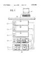
- FIG. 1illustrates the redundant power supply of the present invention powering for network devices connected to a computer network.
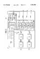
- FIG. 2illustrates a block diagram of the internal features of the redundant power supply of the present invention.
- FIG. 1illustrates four network devices (120, 130, 140 and 150) powered by the redundant power supply 200 of the present invention.
- the network devices 120, 130, 140, and 150are used to implement various functions for the computer network 112.
- the network devices 120, 130, 140, and 150may comprise switches, hubs, gateways, routers, remote access servers, or other devices used to construct a computer network.
- the network management workstation 110is used to control various network devices connected to the computer network 112 using a network management protocol.
- the network management workstation 110communicates with the network devices using the well-known simple network management protocol (SNMP).
- SNMPsimple network management protocol
- each network device 120, 130, 140, and 150has its own internal power supply (121, 131, 141, and 151) to power the network device.
- power suppliesmay eventually fail and require replacement.
- each of the network devices 120, 130, 140, and 150are also powered by the redundant power supply 200. If the internal power supply (121, 131, 141, or 151) of one of the networks devices fails, the respective network device (120, 130, 140, or 150) will then receive power from the redundant power supply 200 in order to continue functioning. Furthermore, the network device with a failed power supply will alert the network management station 110 that its power supply has failed such that the failed power supply may be replaced.
- redundant power supply 200also includes a backup battery 240. If the alternating current (AC) power from the utility company is cut off then the redundant power supply 200 begins powering all the network units 120, 130, 140, and 150 using the battery 240.
- ACalternating current
- FIG. 2illustrates an internal diagram of the redundant power supply 200.
- a first power supply pathcomprises a connection to a utility company AC line to transformer 251 that generates a 380 volt Direct Current (DC) Bus.
- the 380 volt DC Busis then regulated down to 55 Volts DC by high voltage bus circuit 261.
- the second power supply pathconsists of transformer 253 that transforms the utility company AC power into a 380 volt DC Bus.
- the 380 volt DC Busis then regulated down to a 55 volt DC power source by high voltage bus circuit 263.
- the 55 volts of DC power from high voltage bus circuit 261 and 263supply a power distribution network 280 that divides the power among a number of power circuit channels.
- a power distribution network 280that divides the power among a number of power circuit channels.
- there are four channels of power outputwherein each channel delivers a +5 volt, +12 volt, and -12 volt power sources.
- Each power channelis controlled by individual control circuitry 281, 282, 283, and 284.
- the back-up battery 240is a 48 volt battery. Back-up battery 240 is charged by the 55 volt DC power from circuit 261. When there is a power failure such that the voltage produced by circuit 261 drops below the battery threshold voltage, then the back-up battery 240 will begin providing power to the power distribution network 280.
- control circuitry section 210receives programming information through a data line 212.
- the data lineis handled by interface circuitry 215.
- the data linemay be a serial line thus, the interface circuitry 215 would be a serial line control circuitry.
- the control circuitry 210controls the 4 individual channel control circuits 281, 282, 283, and 284. Each channel control circuit can individually be turned on or off. Thus, the control circuitry 210 can decide which channels will receive power.
- the data received over the data line 212is used to program a set of control registers 218.
- the control registers 218define a set of parameters that will control how the redundant power supply 200 operates during a power failure. Specifically, the control registers 218 define exactly how the redundant power supply 200 will allocate power from the internal battery 240 to the four different network devices.
- each register for each power channelthere is one register for each power channel.
- the register for each power channelstores a "hold-up" time that defines how long the control circuitry 210 will provide to that power channel.
- a reserved valuewill be used to indicate that the control circuitry 210 should hold that power channel until the battery is discharged.
- the control circuitry 210sets each of the timer circuits 213 with the holdup times from the control registers 218 (except for registers that contain the reserved value designated for infinite hold-up).
- each timer circuit popsits corresponding power channel is turned off using its channel control circuit (281, 282, 283, or 284). Eventually, only the power channels designated for infinite hold-up will receive power.
- the control register valuesdefine a "switchout voltage threshold.”
- the switchout voltage thresholddefines a battery voltage level at what a power channel will be cut off from battery power.
- the power control circuitry 211provides power to all the power channels.
- the power control circuitry 211then constantly monitors the voltage level of the battery 240.
- the power control circuitry 211detects that the battery 240 voltage level equals the switchout voltage threshold for a particular power channel, then the power control circuitry 211 switches off the power for that power channel using its channel control circuit (281, 282, 283, or 284). If the switchout voltage threshold for a power channel is set to zero, then that power channel will receive power until the battery is discharged.
- the redundant power supply 200provides back-up power to four networks units.
- network device 120is an unimportant network device
- network device 130is a hub for a user LAN
- network device 140is a hub for a server LAN
- network device 150is a switch for the corporate backbone.
- power channel for network device 120may be programmed for 4 minutes of battery holdup such that the users can quit their applications and log off the network and the power channel for network device 120 may programmed to 5 minutes of battery holdup such that the servers may automatically shut-down.
- the power channel for unimportant network device 120programmed for no holdup and thus conserve battery power for more important usage.
- the power channel for corporate backbone switchmay be programmed to be held up by batteries until complete battery discharge state is reached. It should be apparent that this invention allows the user to program a backup power holdup priority, for a complex multiple node system, with a single backup energy storage device and power routing hardware and software.
- the data line 212is grouped together with one of the power supply lines that supplies power to one of the network devices.
- one of the network devicesis used to program the redundant power supply 200.
- network device 150is used to program the redundant power supply 200.
- Network device 150is a controllable network device that is controlled by control circuit 153.
- Control circuit 153 of network device 150is controlled remotely by the network management workstation 110 connected to the network 112.
- the network management workstation 110controls network device 150 sending packets encoded in the simple network management protocol (SNMP).
- SNMPsimple network management protocol
- the network management device network management workstation 110sends special SNMP control commands to the control circuit 153 of network device 150. These special control commands are interpreted by the control circuit 153 as redundant power supply programming commands.
- control circuit 153uses interface circuit 155 to send the control commands through data line 212 to the control circuit 210 in the redundant power supply.
- interface circuitry 215receives and interprets the control commands such that interface circuitry 215 sets the control registers 218 properly.
Landscapes
- Engineering & Computer Science (AREA)
- Power Engineering (AREA)
- Theoretical Computer Science (AREA)
- Physics & Mathematics (AREA)
- General Engineering & Computer Science (AREA)
- General Physics & Mathematics (AREA)
- Business, Economics & Management (AREA)
- Emergency Management (AREA)
- Stand-By Power Supply Arrangements (AREA)
- Power Sources (AREA)
Abstract
Description
Claims (12)
Priority Applications (1)
| Application Number | Priority Date | Filing Date | Title |
|---|---|---|---|
| US08/688,807US5761084A (en) | 1996-07-31 | 1996-07-31 | Highly programmable backup power scheme |
Applications Claiming Priority (1)
| Application Number | Priority Date | Filing Date | Title |
|---|---|---|---|
| US08/688,807US5761084A (en) | 1996-07-31 | 1996-07-31 | Highly programmable backup power scheme |
Publications (1)
| Publication Number | Publication Date |
|---|---|
| US5761084Atrue US5761084A (en) | 1998-06-02 |
Family
ID=24765868
Family Applications (1)
| Application Number | Title | Priority Date | Filing Date |
|---|---|---|---|
| US08/688,807Expired - LifetimeUS5761084A (en) | 1996-07-31 | 1996-07-31 | Highly programmable backup power scheme |
Country Status (1)
| Country | Link |
|---|---|
| US (1) | US5761084A (en) |
Cited By (75)
| Publication number | Priority date | Publication date | Assignee | Title |
|---|---|---|---|---|
| US5949974A (en)* | 1996-07-23 | 1999-09-07 | Ewing; Carrell W. | System for reading the status and for controlling the power supplies of appliances connected to computer networks |
| WO1999067703A1 (en)* | 1998-06-22 | 1999-12-29 | Ephrath, Ezra | Automatic resumption of computer operation following power failure |
| US6014319A (en)* | 1998-05-21 | 2000-01-11 | International Business Machines Corporation | Multi-part concurrently maintainable electronic circuit card assembly |
| US6041414A (en)* | 1996-12-03 | 2000-03-21 | Fujitsu Limited | Uninterruptible power supply apparatus which supplies guaranteed power to electronic apparatuses in a system |
| US6181029B1 (en)* | 1998-11-06 | 2001-01-30 | International Business Machines Corporation | Method of controlling battery back-up for multiple power supplies |
| US20020002593A1 (en)* | 1996-07-23 | 2002-01-03 | Ewing Carrel W. | Vertical-mount electrical power distribution plugstrip |
| US20020002582A1 (en)* | 1996-07-23 | 2002-01-03 | Ewing Carrel W. | Power-manager configuration upload and download method and system for network managers |
| US20020036430A1 (en)* | 2000-09-28 | 2002-03-28 | Welches Richard S. | Local area grid for distributed power |
| US6476519B1 (en)* | 2000-04-06 | 2002-11-05 | Marconi Communications, Inc. | Power back-up unit with low voltage disconnects that provide load shedding |
| US20030036819A1 (en)* | 1999-01-12 | 2003-02-20 | Amir Lehr | Data communication network |
| US20030084358A1 (en)* | 2001-10-31 | 2003-05-01 | Bresniker Kirk M. | System and method for intelligent control of power consumption of distributed services during periods of reduced load |
| US20030084359A1 (en)* | 2001-10-31 | 2003-05-01 | Bresniker Kirk M. | System and method for intelligent control of power consumption of distributed services during periods when power consumption must be reduced |
| US6581163B1 (en)* | 1999-12-07 | 2003-06-17 | Cisco Technology, Inc. | Mains loss detection apparatus and method |
| US20030126253A1 (en)* | 1996-07-23 | 2003-07-03 | Ewing Carrel W. | Network remote power management outlet strip |
| EP1122850A3 (en)* | 2000-01-15 | 2004-01-28 | Goodrich Actuation Systems Ltd | Apparatus and method for supplying and controlling electrical power |
| US6735704B1 (en) | 2000-10-20 | 2004-05-11 | International Business Machines Corporation | Autonomic control of power subsystems in a redundant power system |
| US20040123165A1 (en)* | 2002-12-21 | 2004-06-24 | Wierzbicki Robert P. | Peer power control |
| US20040172527A1 (en)* | 1998-06-26 | 2004-09-02 | Canon Kabushiki Kaisha | System having devices connected via communication lines |
| US20040205181A1 (en)* | 1996-07-23 | 2004-10-14 | Ewing Carrell W. | Remote power control system |
| EP1482720A1 (en)* | 2003-05-28 | 2004-12-01 | Ricoh Company, Ltd. | Image processing apparatus and computer product |
| US6856045B1 (en)* | 2002-01-29 | 2005-02-15 | Hamilton Sundstrand Corporation | Power distribution assembly with redundant architecture |
| US20060146461A1 (en)* | 2005-01-06 | 2006-07-06 | Jones Carl E | Apparatus, system, and method for maximizing power system holdup time during loss of input power |
| US7099934B1 (en) | 1996-07-23 | 2006-08-29 | Ewing Carrel W | Network-connecting power manager for remote appliances |
| US7301313B1 (en)* | 1999-03-23 | 2007-11-27 | Intel Corporation | Multiple voltage regulators for use with a single load |
| US20080024008A1 (en)* | 2006-07-05 | 2008-01-31 | Ting-Yin Chiu | Household self-contained power supply |
| US20090022058A1 (en)* | 2006-03-27 | 2009-01-22 | Huawei Technologies Co., Ltd. | Method and System for Detecting and Reporting Faults of Data Transmission Equipment |
| US20100026092A1 (en)* | 2006-12-19 | 2010-02-04 | Takuma Iida | Power source system, power supply control method of power source system, power supply control program of power source system, and computer readable recording medium having power supply control program of power source system recorded thereon |
| US7743125B1 (en)* | 2000-11-09 | 2010-06-22 | General Electric Company | Computer multiple communications port unit |
| US20100165189A1 (en)* | 2007-06-07 | 2010-07-01 | Opticis Co., Ltd | Digital image transmission system transmitting digital image data |
| WO2010076106A1 (en)* | 2008-12-08 | 2010-07-08 | Sinitec Vertriebsgesellschaft Mbh | Assembly comprising at least two power supply units and at least one power consuming component, computer system and method for control of an assembly |
| US20110029788A1 (en)* | 2009-07-31 | 2011-02-03 | Domingo Reynaldo P | Power Limiting In Redundant Power Supply Systems |
| US20110184586A1 (en)* | 2010-01-25 | 2011-07-28 | Tomoyuki Asano | Power management apparatus, and method of registering electronic appliances |
| US8093749B1 (en)* | 2008-01-29 | 2012-01-10 | Juniper Networks, Inc. | Sharing redundant power supply modules among physical systems |
| US8155012B2 (en) | 1998-04-10 | 2012-04-10 | Chrimar Systems, Inc. | System and method for adapting a piece of terminal equipment |
| US20120232711A1 (en)* | 2009-11-30 | 2012-09-13 | Kyocera Corporation | Control system, correction device, and power control method |
| EP2009763A3 (en)* | 2007-06-29 | 2014-01-01 | Diehl AKO Stiftung & Co. KG | Electricity supply device |
| US8736107B1 (en)* | 2010-12-28 | 2014-05-27 | Amazon Technologies, Inc. | Power source redundancy in a power supply |
| US9047360B2 (en) | 2008-12-08 | 2015-06-02 | Fujitsu Technology Solutions Intellectual Property Gmbh | Apparatus and method for controlling a computer system with at least two power supply units |
| US9703342B2 (en) | 2012-02-10 | 2017-07-11 | Server Technology, Inc. | System and method for configuring plurality of linked power distribution units in which configuration data of the linked power distribution units are accessible by the remote system |
| US20170302103A1 (en)* | 2016-04-18 | 2017-10-19 | General Electric Company | Auxiliary power for luminiare node controllers |
| US10481660B1 (en)* | 2019-04-25 | 2019-11-19 | Michael Feldman | Batteryless data logger with backup status indication and method therefor |
| CN110991791A (en)* | 2019-10-22 | 2020-04-10 | 国网浙江省电力有限公司宁波供电公司 | Method and system for integrated allocation of distribution station resources based on fog computing model |
| WO2020242775A1 (en)* | 2019-05-30 | 2020-12-03 | Cisco Technology, Inc. | Cloud-managed allocation of a network's power use to control runtime on backup battery |
| US20230055844A1 (en)* | 2019-09-13 | 2023-02-23 | Bj Energy Solutions, Llc | Power sources and transmission networks for auxiliary equipment onboard hydraulic fracturing units and associated methods |
| US11603745B2 (en) | 2020-05-28 | 2023-03-14 | Bj Energy Solutions, Llc | Bi-fuel reciprocating engine to power direct drive turbine fracturing pumps onboard auxiliary systems and related methods |
| US11603744B2 (en) | 2020-07-17 | 2023-03-14 | Bj Energy Solutions, Llc | Methods, systems, and devices to enhance fracturing fluid delivery to subsurface formations during high-pressure fracturing operations |
| US11604113B2 (en) | 2019-09-13 | 2023-03-14 | Bj Energy Solutions, Llc | Fuel, communications, and power connection systems and related methods |
| US11608725B2 (en) | 2019-09-13 | 2023-03-21 | Bj Energy Solutions, Llc | Methods and systems for operating a fleet of pumps |
| US11624321B2 (en) | 2020-05-15 | 2023-04-11 | Bj Energy Solutions, Llc | Onboard heater of auxiliary systems using exhaust gases and associated methods |
| US11624326B2 (en) | 2017-05-21 | 2023-04-11 | Bj Energy Solutions, Llc | Methods and systems for supplying fuel to gas turbine engines |
| US11629583B2 (en) | 2020-06-09 | 2023-04-18 | Bj Energy Solutions, Llc | Systems and methods for exchanging fracturing components of a hydraulic fracturing unit |
| US11635074B2 (en) | 2020-05-12 | 2023-04-25 | Bj Energy Solutions, Llc | Cover for fluid systems and related methods |
| US11643915B2 (en) | 2020-06-09 | 2023-05-09 | Bj Energy Solutions, Llc | Drive equipment and methods for mobile fracturing transportation platforms |
| US11649766B1 (en) | 2019-09-13 | 2023-05-16 | Bj Energy Solutions, Llc | Mobile gas turbine inlet air conditioning system and associated methods |
| US11649820B2 (en) | 2020-06-23 | 2023-05-16 | Bj Energy Solutions, Llc | Systems and methods of utilization of a hydraulic fracturing unit profile to operate hydraulic fracturing units |
| US11655763B1 (en) | 2019-09-13 | 2023-05-23 | Bj Energy Solutions, Llc | Direct drive unit removal system and associated methods |
| US11661832B2 (en) | 2020-06-23 | 2023-05-30 | Bj Energy Solutions, Llc | Systems and methods to autonomously operate hydraulic fracturing units |
| US11668175B2 (en) | 2020-06-24 | 2023-06-06 | Bj Energy Solutions, Llc | Automated diagnostics of electronic instrumentation in a system for fracturing a well and associated methods |
| US11692422B2 (en) | 2020-06-24 | 2023-07-04 | Bj Energy Solutions, Llc | System to monitor cavitation or pulsation events during a hydraulic fracturing operation |
| US11719234B2 (en) | 2019-09-13 | 2023-08-08 | Bj Energy Solutions, Llc | Systems and method for use of single mass flywheel alongside torsional vibration damper assembly for single acting reciprocating pump |
| US11723171B2 (en) | 2020-06-05 | 2023-08-08 | Bj Energy Solutions, Llc | Enclosure assembly for enhanced cooling of direct drive unit and related methods |
| US11732563B2 (en) | 2021-05-24 | 2023-08-22 | Bj Energy Solutions, Llc | Hydraulic fracturing pumps to enhance flow of fracturing fluid into wellheads and related methods |
| US11732565B2 (en) | 2020-06-22 | 2023-08-22 | Bj Energy Solutions, Llc | Systems and methods to operate a dual-shaft gas turbine engine for hydraulic fracturing |
| US11746698B2 (en) | 2020-06-05 | 2023-09-05 | Bj Energy Solutions, Llc | Systems and methods to enhance intake air flow to a gas turbine engine of a hydraulic fracturing unit |
| US11761846B2 (en) | 2019-09-13 | 2023-09-19 | Bj Energy Solutions, Llc | Fuel, communications, and power connection systems and related methods |
| US11867118B2 (en) | 2019-09-13 | 2024-01-09 | Bj Energy Solutions, Llc | Methods and systems for supplying fuel to gas turbine engines |
| US11898504B2 (en) | 2020-05-14 | 2024-02-13 | Bj Energy Solutions, Llc | Systems and methods utilizing turbine compressor discharge for hydrostatic manifold purge |
| US11933153B2 (en) | 2020-06-22 | 2024-03-19 | Bj Energy Solutions, Llc | Systems and methods to operate hydraulic fracturing units using automatic flow rate and/or pressure control |
| US11939853B2 (en) | 2020-06-22 | 2024-03-26 | Bj Energy Solutions, Llc | Systems and methods providing a configurable staged rate increase function to operate hydraulic fracturing units |
| US11939854B2 (en) | 2020-06-09 | 2024-03-26 | Bj Energy Solutions, Llc | Methods for detection and mitigation of well screen out |
| US11952878B2 (en) | 2020-06-22 | 2024-04-09 | Bj Energy Solutions, Llc | Stage profiles for operations of hydraulic systems and associated methods |
| US12065968B2 (en) | 2019-09-13 | 2024-08-20 | BJ Energy Solutions, Inc. | Systems and methods for hydraulic fracturing |
| US12281964B2 (en) | 2019-09-13 | 2025-04-22 | Bj Energy Solutions, Llc | Fuel, communications, and power connection systems and related methods |
| US12338772B2 (en) | 2019-09-13 | 2025-06-24 | Bj Energy Solutions, Llc | Systems, assemblies, and methods to enhance intake air flow to a gas turbine engine of a hydraulic fracturing unit |
| US12378864B2 (en) | 2021-10-25 | 2025-08-05 | Bj Energy Solutions, Llc | Systems and methods to reduce acoustic resonance or disrupt standing wave formation in a fluid manifold of a high-pressure fracturing system |
Citations (12)
| Publication number | Priority date | Publication date | Assignee | Title |
|---|---|---|---|---|
| US3614566A (en)* | 1969-02-06 | 1971-10-19 | Sulzer Ag | Control device having means for electrically simulating and compensating the inertia momentum of the moving parts of an electrical positioning means |
| US4007472A (en)* | 1974-08-08 | 1977-02-08 | Polaroid Corporation | Flat battery with dry cathode strata and slurry cathode strata |
| US4335445A (en)* | 1979-02-26 | 1982-06-15 | Kepco, Inc. | System for interfacing computers with programmable power supplies |
| US4677311A (en)* | 1984-12-29 | 1987-06-30 | Hitachi, Ltd. | Power supply system for an electronic apparatus having memory |
| US5087872A (en)* | 1990-02-13 | 1992-02-11 | Deltec Electronics Corporation | Circulating load apparatus |
| US5266838A (en)* | 1991-12-05 | 1993-11-30 | Thinking Machines Corporation | Power supply system including power sharing control arrangement |
| US5339446A (en)* | 1986-12-26 | 1994-08-16 | Kabushiki Kaisha Toshiba | Power supply and method for use in a computer system to confirm a save operation of the computer system and to stop a supply of power to the computer system after confirmation |
| US5390188A (en)* | 1993-08-02 | 1995-02-14 | Synoptics | Method and apparatus for measuring and monitoring the performance within a ring communication network |
| US5420493A (en)* | 1992-06-30 | 1995-05-30 | Apple Computer, Inc. | Power supply and battery charger |
| US5532524A (en)* | 1994-05-11 | 1996-07-02 | Apple Computer, Inc. | Distributed power regulation in a portable computer to optimize heat dissipation and maximize battery run-time for various power modes |
| US5548206A (en)* | 1993-09-30 | 1996-08-20 | National Semiconductor Corporation | System and method for dual mode DC-DC power conversion |
| US5567993A (en)* | 1994-06-23 | 1996-10-22 | Dallas Semiconductor Corporation | Programmable power supply system and methods |
- 1996
- 1996-07-31USUS08/688,807patent/US5761084A/ennot_activeExpired - Lifetime
Patent Citations (12)
| Publication number | Priority date | Publication date | Assignee | Title |
|---|---|---|---|---|
| US3614566A (en)* | 1969-02-06 | 1971-10-19 | Sulzer Ag | Control device having means for electrically simulating and compensating the inertia momentum of the moving parts of an electrical positioning means |
| US4007472A (en)* | 1974-08-08 | 1977-02-08 | Polaroid Corporation | Flat battery with dry cathode strata and slurry cathode strata |
| US4335445A (en)* | 1979-02-26 | 1982-06-15 | Kepco, Inc. | System for interfacing computers with programmable power supplies |
| US4677311A (en)* | 1984-12-29 | 1987-06-30 | Hitachi, Ltd. | Power supply system for an electronic apparatus having memory |
| US5339446A (en)* | 1986-12-26 | 1994-08-16 | Kabushiki Kaisha Toshiba | Power supply and method for use in a computer system to confirm a save operation of the computer system and to stop a supply of power to the computer system after confirmation |
| US5087872A (en)* | 1990-02-13 | 1992-02-11 | Deltec Electronics Corporation | Circulating load apparatus |
| US5266838A (en)* | 1991-12-05 | 1993-11-30 | Thinking Machines Corporation | Power supply system including power sharing control arrangement |
| US5420493A (en)* | 1992-06-30 | 1995-05-30 | Apple Computer, Inc. | Power supply and battery charger |
| US5390188A (en)* | 1993-08-02 | 1995-02-14 | Synoptics | Method and apparatus for measuring and monitoring the performance within a ring communication network |
| US5548206A (en)* | 1993-09-30 | 1996-08-20 | National Semiconductor Corporation | System and method for dual mode DC-DC power conversion |
| US5532524A (en)* | 1994-05-11 | 1996-07-02 | Apple Computer, Inc. | Distributed power regulation in a portable computer to optimize heat dissipation and maximize battery run-time for various power modes |
| US5567993A (en)* | 1994-06-23 | 1996-10-22 | Dallas Semiconductor Corporation | Programmable power supply system and methods |
Cited By (142)
| Publication number | Priority date | Publication date | Assignee | Title |
|---|---|---|---|---|
| US7043543B2 (en) | 1996-07-23 | 2006-05-09 | Server Technology, Inc. | Vertical-mount electrical power distribution plugstrip |
| US7010589B2 (en) | 1996-07-23 | 2006-03-07 | Server Technology, Inc. | Remote power control system |
| US20040205181A1 (en)* | 1996-07-23 | 2004-10-14 | Ewing Carrell W. | Remote power control system |
| US9104393B2 (en) | 1996-07-23 | 2015-08-11 | Server Technology, Inc. | Power-manager configuration upload and download method and system for network managers |
| US20020002593A1 (en)* | 1996-07-23 | 2002-01-03 | Ewing Carrel W. | Vertical-mount electrical power distribution plugstrip |
| US20020002582A1 (en)* | 1996-07-23 | 2002-01-03 | Ewing Carrel W. | Power-manager configuration upload and download method and system for network managers |
| US7171461B2 (en) | 1996-07-23 | 2007-01-30 | Server Technology, Inc. | Network remote power management outlet strip |
| US7099934B1 (en) | 1996-07-23 | 2006-08-29 | Ewing Carrel W | Network-connecting power manager for remote appliances |
| US20030126253A1 (en)* | 1996-07-23 | 2003-07-03 | Ewing Carrel W. | Network remote power management outlet strip |
| US5949974A (en)* | 1996-07-23 | 1999-09-07 | Ewing; Carrell W. | System for reading the status and for controlling the power supplies of appliances connected to computer networks |
| US9450386B2 (en) | 1996-07-23 | 2016-09-20 | Server Technology, Inc. | Vertical-mount electrical power distribution plugstrip |
| US6041414A (en)* | 1996-12-03 | 2000-03-21 | Fujitsu Limited | Uninterruptible power supply apparatus which supplies guaranteed power to electronic apparatuses in a system |
| US8155012B2 (en) | 1998-04-10 | 2012-04-10 | Chrimar Systems, Inc. | System and method for adapting a piece of terminal equipment |
| US8902760B2 (en) | 1998-04-10 | 2014-12-02 | Chrimar Systems, Inc. | Network system and optional tethers |
| US9812825B2 (en) | 1998-04-10 | 2017-11-07 | Chrimar Systems, Inc. | Ethernet device |
| US9049019B2 (en) | 1998-04-10 | 2015-06-02 | Chrimar Systems, Inc. | Network equipment and optional tether |
| US9019838B2 (en) | 1998-04-10 | 2015-04-28 | Chrimar Systems, Inc. | Central piece of network equipment |
| US8942107B2 (en) | 1998-04-10 | 2015-01-27 | Chrimar Systems, Inc. | Piece of ethernet terminal equipment |
| US6014319A (en)* | 1998-05-21 | 2000-01-11 | International Business Machines Corporation | Multi-part concurrently maintainable electronic circuit card assembly |
| WO1999067703A1 (en)* | 1998-06-22 | 1999-12-29 | Ephrath, Ezra | Automatic resumption of computer operation following power failure |
| US20040172527A1 (en)* | 1998-06-26 | 2004-09-02 | Canon Kabushiki Kaisha | System having devices connected via communication lines |
| US6181029B1 (en)* | 1998-11-06 | 2001-01-30 | International Business Machines Corporation | Method of controlling battery back-up for multiple power supplies |
| US20030036819A1 (en)* | 1999-01-12 | 2003-02-20 | Amir Lehr | Data communication network |
| US6985713B2 (en)* | 1999-01-12 | 2006-01-10 | Powerdsine, Ltd. | Data communication network providing power over network connections with node identification functionality |
| US7301313B1 (en)* | 1999-03-23 | 2007-11-27 | Intel Corporation | Multiple voltage regulators for use with a single load |
| US20030201779A1 (en)* | 1999-12-07 | 2003-10-30 | John Sisler | Mains loss detection apparatus and method |
| US7013399B2 (en)* | 1999-12-07 | 2006-03-14 | Cisco Technology, Inc. | Power supply apparatus to detect power failure and use signaling voltages to issue network alert |
| US6581163B1 (en)* | 1999-12-07 | 2003-06-17 | Cisco Technology, Inc. | Mains loss detection apparatus and method |
| EP1122850A3 (en)* | 2000-01-15 | 2004-01-28 | Goodrich Actuation Systems Ltd | Apparatus and method for supplying and controlling electrical power |
| US6476519B1 (en)* | 2000-04-06 | 2002-11-05 | Marconi Communications, Inc. | Power back-up unit with low voltage disconnects that provide load shedding |
| US20020036430A1 (en)* | 2000-09-28 | 2002-03-28 | Welches Richard S. | Local area grid for distributed power |
| US6735704B1 (en) | 2000-10-20 | 2004-05-11 | International Business Machines Corporation | Autonomic control of power subsystems in a redundant power system |
| US7743125B1 (en)* | 2000-11-09 | 2010-06-22 | General Electric Company | Computer multiple communications port unit |
| US20030084358A1 (en)* | 2001-10-31 | 2003-05-01 | Bresniker Kirk M. | System and method for intelligent control of power consumption of distributed services during periods of reduced load |
| US7043650B2 (en)* | 2001-10-31 | 2006-05-09 | Hewlett-Packard Development Company, L.P. | System and method for intelligent control of power consumption of distributed services during periods when power consumption must be reduced |
| US7203846B2 (en)* | 2001-10-31 | 2007-04-10 | Hewlett-Packard Development Company, Lp. | System and method for intelligent control of power consumption of distributed services during periods of reduced load |
| US20030084359A1 (en)* | 2001-10-31 | 2003-05-01 | Bresniker Kirk M. | System and method for intelligent control of power consumption of distributed services during periods when power consumption must be reduced |
| US6856045B1 (en)* | 2002-01-29 | 2005-02-15 | Hamilton Sundstrand Corporation | Power distribution assembly with redundant architecture |
| US7127621B2 (en)* | 2002-12-21 | 2006-10-24 | Emc Corporation | Peer power control |
| US20040123165A1 (en)* | 2002-12-21 | 2004-06-24 | Wierzbicki Robert P. | Peer power control |
| US20050012953A1 (en)* | 2003-05-28 | 2005-01-20 | Takezo Fujishige | Image processing apparatus and computer product |
| US7701600B2 (en)* | 2003-05-28 | 2010-04-20 | Ricoh Company, Ltd. | Image processing apparatus and computer product |
| EP1482720A1 (en)* | 2003-05-28 | 2004-12-01 | Ricoh Company, Ltd. | Image processing apparatus and computer product |
| US20060146461A1 (en)* | 2005-01-06 | 2006-07-06 | Jones Carl E | Apparatus, system, and method for maximizing power system holdup time during loss of input power |
| US7321174B2 (en)* | 2005-01-06 | 2008-01-22 | International Business Machines Corporation | Apparatus, system, and method for maximizing power system holdup time during loss of input power |
| US20090022058A1 (en)* | 2006-03-27 | 2009-01-22 | Huawei Technologies Co., Ltd. | Method and System for Detecting and Reporting Faults of Data Transmission Equipment |
| US20080024008A1 (en)* | 2006-07-05 | 2008-01-31 | Ting-Yin Chiu | Household self-contained power supply |
| US20100026092A1 (en)* | 2006-12-19 | 2010-02-04 | Takuma Iida | Power source system, power supply control method of power source system, power supply control program of power source system, and computer readable recording medium having power supply control program of power source system recorded thereon |
| US8276005B2 (en)* | 2007-06-07 | 2012-09-25 | Opticis Co., Ltd. | Digital image transmission system transmitting digital image data |
| US20100165189A1 (en)* | 2007-06-07 | 2010-07-01 | Opticis Co., Ltd | Digital image transmission system transmitting digital image data |
| EP2009763A3 (en)* | 2007-06-29 | 2014-01-01 | Diehl AKO Stiftung & Co. KG | Electricity supply device |
| US8093749B1 (en)* | 2008-01-29 | 2012-01-10 | Juniper Networks, Inc. | Sharing redundant power supply modules among physical systems |
| US9276405B2 (en) | 2008-01-29 | 2016-03-01 | Juniper Networks, Inc. | Sharing redundant power supply modules among physical systems |
| US9077203B2 (en) | 2008-12-08 | 2015-07-07 | Fujitsu Technology Solutions Intellectual Property Gmbh | Assembly with at least two power supply units and at least one power-consuming component, computer system and method for control of an assembly |
| US9047360B2 (en) | 2008-12-08 | 2015-06-02 | Fujitsu Technology Solutions Intellectual Property Gmbh | Apparatus and method for controlling a computer system with at least two power supply units |
| WO2010076106A1 (en)* | 2008-12-08 | 2010-07-08 | Sinitec Vertriebsgesellschaft Mbh | Assembly comprising at least two power supply units and at least one power consuming component, computer system and method for control of an assembly |
| US8312300B2 (en)* | 2009-07-31 | 2012-11-13 | Hewlett-Packard Development Company, L.P. | Limiting power in redundant power supply systems |
| US20110029788A1 (en)* | 2009-07-31 | 2011-02-03 | Domingo Reynaldo P | Power Limiting In Redundant Power Supply Systems |
| US9190873B2 (en)* | 2009-11-30 | 2015-11-17 | Kyocera Corporation | Control system, correction device, and power control method |
| US20120232711A1 (en)* | 2009-11-30 | 2012-09-13 | Kyocera Corporation | Control system, correction device, and power control method |
| CN102194157A (en)* | 2010-01-25 | 2011-09-21 | 索尼公司 | Power management apparatus, and method of registering electronic appliances |
| US20110184586A1 (en)* | 2010-01-25 | 2011-07-28 | Tomoyuki Asano | Power management apparatus, and method of registering electronic appliances |
| US8736107B1 (en)* | 2010-12-28 | 2014-05-27 | Amazon Technologies, Inc. | Power source redundancy in a power supply |
| US9705321B1 (en) | 2010-12-28 | 2017-07-11 | Amazon Technologies, Inc. | Power source redundancy in a power supply |
| US20170271869A1 (en)* | 2010-12-28 | 2017-09-21 | Amazon Technologies, Inc. | Power source redundancy in a power supply |
| US10622807B2 (en)* | 2010-12-28 | 2020-04-14 | Amazon Technologies, Inc. | Power source redundancy in a power supply |
| US10983578B2 (en) | 2012-02-10 | 2021-04-20 | Server Technology, Inc. | Systems and methods for configuring a power distribution unit |
| US9703342B2 (en) | 2012-02-10 | 2017-07-11 | Server Technology, Inc. | System and method for configuring plurality of linked power distribution units in which configuration data of the linked power distribution units are accessible by the remote system |
| US12189447B2 (en) | 2012-02-10 | 2025-01-07 | Legrand DPC, LLC | Systems and methods for configuring a power distribution unit |
| US20170302103A1 (en)* | 2016-04-18 | 2017-10-19 | General Electric Company | Auxiliary power for luminiare node controllers |
| US11624326B2 (en) | 2017-05-21 | 2023-04-11 | Bj Energy Solutions, Llc | Methods and systems for supplying fuel to gas turbine engines |
| US10481660B1 (en)* | 2019-04-25 | 2019-11-19 | Michael Feldman | Batteryless data logger with backup status indication and method therefor |
| WO2020242775A1 (en)* | 2019-05-30 | 2020-12-03 | Cisco Technology, Inc. | Cloud-managed allocation of a network's power use to control runtime on backup battery |
| CN113874811A (en)* | 2019-05-30 | 2021-12-31 | 思科技术公司 | Cloud management allocation of power usage to a network to control backup battery runtime |
| AU2020283454B2 (en)* | 2019-05-30 | 2024-10-31 | Cisco Technology, Inc. | Cloud-managed allocation of a network's power use to control runtime on backup battery |
| AU2020283454C1 (en)* | 2019-05-30 | 2025-03-06 | Cisco Technology, Inc. | Cloud-managed allocation of a network's power use to control runtime on backup battery |
| US12338772B2 (en) | 2019-09-13 | 2025-06-24 | Bj Energy Solutions, Llc | Systems, assemblies, and methods to enhance intake air flow to a gas turbine engine of a hydraulic fracturing unit |
| US20230055844A1 (en)* | 2019-09-13 | 2023-02-23 | Bj Energy Solutions, Llc | Power sources and transmission networks for auxiliary equipment onboard hydraulic fracturing units and associated methods |
| US11608725B2 (en) | 2019-09-13 | 2023-03-21 | Bj Energy Solutions, Llc | Methods and systems for operating a fleet of pumps |
| US12281964B2 (en) | 2019-09-13 | 2025-04-22 | Bj Energy Solutions, Llc | Fuel, communications, and power connection systems and related methods |
| US11613980B2 (en) | 2019-09-13 | 2023-03-28 | Bj Energy Solutions, Llc | Methods and systems for operating a fleet of pumps |
| US11619122B2 (en) | 2019-09-13 | 2023-04-04 | Bj Energy Solutions, Llc | Methods and systems for operating a fleet of pumps |
| US12276577B2 (en) | 2019-09-13 | 2025-04-15 | Bj Energy Solutions, Llc | Fuel, communications, and power connection systems and related methods |
| US11761846B2 (en) | 2019-09-13 | 2023-09-19 | Bj Energy Solutions, Llc | Fuel, communications, and power connection systems and related methods |
| US11767791B2 (en) | 2019-09-13 | 2023-09-26 | Bj Energy Solutions, Llc | Mobile gas turbine inlet air conditioning system and associated methods |
| US11629584B2 (en)* | 2019-09-13 | 2023-04-18 | Bj Energy Solutions, Llc | Power sources and transmission networks for auxiliary equipment onboard hydraulic fracturing units and associated methods |
| US11852001B2 (en) | 2019-09-13 | 2023-12-26 | Bj Energy Solutions, Llc | Methods and systems for operating a fleet of pumps |
| US11867118B2 (en) | 2019-09-13 | 2024-01-09 | Bj Energy Solutions, Llc | Methods and systems for supplying fuel to gas turbine engines |
| US11649766B1 (en) | 2019-09-13 | 2023-05-16 | Bj Energy Solutions, Llc | Mobile gas turbine inlet air conditioning system and associated methods |
| US11604113B2 (en) | 2019-09-13 | 2023-03-14 | Bj Energy Solutions, Llc | Fuel, communications, and power connection systems and related methods |
| US11655763B1 (en) | 2019-09-13 | 2023-05-23 | Bj Energy Solutions, Llc | Direct drive unit removal system and associated methods |
| US12065968B2 (en) | 2019-09-13 | 2024-08-20 | BJ Energy Solutions, Inc. | Systems and methods for hydraulic fracturing |
| US12049808B2 (en) | 2019-09-13 | 2024-07-30 | Bj Energy Solutions, Llc | Methods and systems for operating a fleet of pumps |
| US11971028B2 (en) | 2019-09-13 | 2024-04-30 | Bj Energy Solutions, Llc | Systems and method for use of single mass flywheel alongside torsional vibration damper assembly for single acting reciprocating pump |
| US11859482B2 (en) | 2019-09-13 | 2024-01-02 | Bj Energy Solutions, Llc | Power sources and transmission networks for auxiliary equipment onboard hydraulic fracturing units and associated methods |
| US11725583B2 (en) | 2019-09-13 | 2023-08-15 | Bj Energy Solutions, Llc | Mobile gas turbine inlet air conditioning system and associated methods |
| US11719234B2 (en) | 2019-09-13 | 2023-08-08 | Bj Energy Solutions, Llc | Systems and method for use of single mass flywheel alongside torsional vibration damper assembly for single acting reciprocating pump |
| CN110991791B (en)* | 2019-10-22 | 2022-06-21 | 国网浙江省电力有限公司宁波供电公司 | Method and system for integrated allocation of distribution station resources based on fog computing model |
| CN110991791A (en)* | 2019-10-22 | 2020-04-10 | 国网浙江省电力有限公司宁波供电公司 | Method and system for integrated allocation of distribution station resources based on fog computing model |
| US11708829B2 (en) | 2020-05-12 | 2023-07-25 | Bj Energy Solutions, Llc | Cover for fluid systems and related methods |
| US11635074B2 (en) | 2020-05-12 | 2023-04-25 | Bj Energy Solutions, Llc | Cover for fluid systems and related methods |
| US12404856B2 (en) | 2020-05-12 | 2025-09-02 | Bj Energy Solutions, Llc | Cover for fluid systems and related methods |
| US11898504B2 (en) | 2020-05-14 | 2024-02-13 | Bj Energy Solutions, Llc | Systems and methods utilizing turbine compressor discharge for hydrostatic manifold purge |
| US11959419B2 (en) | 2020-05-15 | 2024-04-16 | Bj Energy Solutions, Llc | Onboard heater of auxiliary systems using exhaust gases and associated methods |
| US11698028B2 (en) | 2020-05-15 | 2023-07-11 | Bj Energy Solutions, Llc | Onboard heater of auxiliary systems using exhaust gases and associated methods |
| US11624321B2 (en) | 2020-05-15 | 2023-04-11 | Bj Energy Solutions, Llc | Onboard heater of auxiliary systems using exhaust gases and associated methods |
| US11814940B2 (en) | 2020-05-28 | 2023-11-14 | Bj Energy Solutions Llc | Bi-fuel reciprocating engine to power direct drive turbine fracturing pumps onboard auxiliary systems and related methods |
| US11603745B2 (en) | 2020-05-28 | 2023-03-14 | Bj Energy Solutions, Llc | Bi-fuel reciprocating engine to power direct drive turbine fracturing pumps onboard auxiliary systems and related methods |
| US11891952B2 (en) | 2020-06-05 | 2024-02-06 | Bj Energy Solutions, Llc | Systems and methods to enhance intake air flow to a gas turbine engine of a hydraulic fracturing unit |
| US11746698B2 (en) | 2020-06-05 | 2023-09-05 | Bj Energy Solutions, Llc | Systems and methods to enhance intake air flow to a gas turbine engine of a hydraulic fracturing unit |
| US12408291B2 (en) | 2020-06-05 | 2025-09-02 | Bj Energy Solutions, Llc | Enclosure assembly for enhanced cooling of direct drive unit and related methods |
| US11723171B2 (en) | 2020-06-05 | 2023-08-08 | Bj Energy Solutions, Llc | Enclosure assembly for enhanced cooling of direct drive unit and related methods |
| US11629583B2 (en) | 2020-06-09 | 2023-04-18 | Bj Energy Solutions, Llc | Systems and methods for exchanging fracturing components of a hydraulic fracturing unit |
| US11643915B2 (en) | 2020-06-09 | 2023-05-09 | Bj Energy Solutions, Llc | Drive equipment and methods for mobile fracturing transportation platforms |
| US12305495B2 (en) | 2020-06-09 | 2025-05-20 | Bj Energy Solutions, Llc | Systems and methods for exchanging fracturing components of a hydraulic fracturing unit |
| US12385379B2 (en) | 2020-06-09 | 2025-08-12 | Bj Energy Solutions, Llc | Methods for detection and mitigation of well screen out |
| US11867046B2 (en) | 2020-06-09 | 2024-01-09 | Bj Energy Solutions, Llc | Systems and methods for exchanging fracturing components of a hydraulic fracturing unit |
| US11939854B2 (en) | 2020-06-09 | 2024-03-26 | Bj Energy Solutions, Llc | Methods for detection and mitigation of well screen out |
| US11933153B2 (en) | 2020-06-22 | 2024-03-19 | Bj Energy Solutions, Llc | Systems and methods to operate hydraulic fracturing units using automatic flow rate and/or pressure control |
| US11952878B2 (en) | 2020-06-22 | 2024-04-09 | Bj Energy Solutions, Llc | Stage profiles for operations of hydraulic systems and associated methods |
| US11939853B2 (en) | 2020-06-22 | 2024-03-26 | Bj Energy Solutions, Llc | Systems and methods providing a configurable staged rate increase function to operate hydraulic fracturing units |
| US12326075B2 (en) | 2020-06-22 | 2025-06-10 | Bj Energy Solutions, Llc | Stage profiles for operations of hydraulic systems and associated methods |
| US11898429B2 (en) | 2020-06-22 | 2024-02-13 | Bj Energy Solutions, Llc | Systems and methods to operate a dual-shaft gas turbine engine for hydraulic fracturing |
| US12286874B2 (en) | 2020-06-22 | 2025-04-29 | Bj Energy Solutions, Llc | Systems and methods to operate hydraulic fracturing units using automatic flow rate and/or pressure control |
| US11732565B2 (en) | 2020-06-22 | 2023-08-22 | Bj Energy Solutions, Llc | Systems and methods to operate a dual-shaft gas turbine engine for hydraulic fracturing |
| US11939974B2 (en) | 2020-06-23 | 2024-03-26 | Bj Energy Solutions, Llc | Systems and methods of utilization of a hydraulic fracturing unit profile to operate hydraulic fracturing units |
| US12065917B2 (en) | 2020-06-23 | 2024-08-20 | Bj Energy Solutions, Llc | Systems and methods to autonomously operate hydraulic fracturing units |
| US11661832B2 (en) | 2020-06-23 | 2023-05-30 | Bj Energy Solutions, Llc | Systems and methods to autonomously operate hydraulic fracturing units |
| US11649820B2 (en) | 2020-06-23 | 2023-05-16 | Bj Energy Solutions, Llc | Systems and methods of utilization of a hydraulic fracturing unit profile to operate hydraulic fracturing units |
| US11719085B1 (en) | 2020-06-23 | 2023-08-08 | Bj Energy Solutions, Llc | Systems and methods to autonomously operate hydraulic fracturing units |
| US11692422B2 (en) | 2020-06-24 | 2023-07-04 | Bj Energy Solutions, Llc | System to monitor cavitation or pulsation events during a hydraulic fracturing operation |
| US12286872B2 (en) | 2020-06-24 | 2025-04-29 | Bj Energy Solutions, Llc | Automated diagnostics of electronic instrumentation in a system for fracturing a well and associated methods |
| US11668175B2 (en) | 2020-06-24 | 2023-06-06 | Bj Energy Solutions, Llc | Automated diagnostics of electronic instrumentation in a system for fracturing a well and associated methods |
| US11746638B2 (en) | 2020-06-24 | 2023-09-05 | Bj Energy Solutions, Llc | Automated diagnostics of electronic instrumentation in a system for fracturing a well and associated methods |
| US11608727B2 (en) | 2020-07-17 | 2023-03-21 | Bj Energy Solutions, Llc | Methods, systems, and devices to enhance fracturing fluid delivery to subsurface formations during high-pressure fracturing operations |
| US11994014B2 (en) | 2020-07-17 | 2024-05-28 | Bj Energy Solutions, Llc | Methods, systems, and devices to enhance fracturing fluid delivery to subsurface formations during high-pressure fracturing operations |
| US11603744B2 (en) | 2020-07-17 | 2023-03-14 | Bj Energy Solutions, Llc | Methods, systems, and devices to enhance fracturing fluid delivery to subsurface formations during high-pressure fracturing operations |
| US11920450B2 (en) | 2020-07-17 | 2024-03-05 | Bj Energy Solutions, Llc | Methods, systems, and devices to enhance fracturing fluid delivery to subsurface formations during high-pressure fracturing operations |
| US11867045B2 (en) | 2021-05-24 | 2024-01-09 | Bj Energy Solutions, Llc | Hydraulic fracturing pumps to enhance flow of fracturing fluid into wellheads and related methods |
| US11732563B2 (en) | 2021-05-24 | 2023-08-22 | Bj Energy Solutions, Llc | Hydraulic fracturing pumps to enhance flow of fracturing fluid into wellheads and related methods |
| US12428943B2 (en) | 2021-05-24 | 2025-09-30 | Bj Energy Solutions, Llc | Hydraulic fracturing pumps to enhance flow of fracturing fluid into wellheads and related methods |
| US12378864B2 (en) | 2021-10-25 | 2025-08-05 | Bj Energy Solutions, Llc | Systems and methods to reduce acoustic resonance or disrupt standing wave formation in a fluid manifold of a high-pressure fracturing system |
Similar Documents
| Publication | Publication Date | Title |
|---|---|---|
| US5761084A (en) | Highly programmable backup power scheme | |
| US7146258B2 (en) | Direct current power pooling | |
| US10003200B2 (en) | Decentralized module-based DC data center | |
| US12126212B2 (en) | Modular ups and working method of modular ups | |
| US5319571A (en) | UPS system with improved network communications | |
| US7478251B1 (en) | Methods and apparatus for provisioning uninterruptible power for power over Ethernet applications | |
| US10764071B1 (en) | System and method for chaining power and communications to multiple nodes | |
| US7145439B2 (en) | Powered device interface circuit | |
| CN100376093C (en) | Local area network and switch, method for switch, method for service node | |
| US8892910B2 (en) | Method and system for providing dynamic power sharing to network devices | |
| US8135965B2 (en) | Apparatus and method for distributed standby power provision | |
| US10749375B2 (en) | System and method for supplying uninterruptible power to a PoE device for a power supply input for direct current power | |
| US20080046768A1 (en) | Transmission of a power loss condition over a network | |
| US10218216B2 (en) | System and method for supplying uninterruptible power to a POE device in a powered state | |
| US9720476B1 (en) | Automatic transfer switch with power quality module | |
| US20070085675A1 (en) | Powered Device with Priority Indicator | |
| US11797070B2 (en) | Response mechanisms for power-interruption events in PoE systems | |
| US10931116B2 (en) | Priority load sharing for electrical power systems having multiple power sources | |
| WO2004051955A1 (en) | Communication unit, control method and program | |
| CN113572214B (en) | Power supply system and operating method thereof | |
| US11437812B2 (en) | Method and device for controlling distributed direct current power supply system | |
| US20030033548A1 (en) | Uninterruptible power supply management network system | |
| CN117878895A (en) | Management method and management device of energy storage system, energy storage system and storage medium | |
| RU2324272C2 (en) | Smart dc voltage converter for dynamically varying load | |
| CN107517106A (en) | A kind of POE method of supplying power to and POE power supply units |
Legal Events
| Date | Code | Title | Description |
|---|---|---|---|
| AS | Assignment | Owner name:BAY NETWORKS, INC., CALIFORNIA Free format text:ASSIGNMENT OF ASSIGNORS INTEREST;ASSIGNOR:EDWARDS, MICHAEL S.;REEL/FRAME:008123/0981 Effective date:19960729 | |
| STCF | Information on status: patent grant | Free format text:PATENTED CASE | |
| AS | Assignment | Owner name:NORTEL NETWORKS NA INC., CALIFORNIA Free format text:CHANGE OF NAME;ASSIGNOR:BAY NETWORKS, INC.;REEL/FRAME:010461/0283 Effective date:19990430 | |
| AS | Assignment | Owner name:NORTEL NETWORKS CORPORATION, CANADA Free format text:ASSIGNMENT OF ASSIGNORS INTEREST;ASSIGNOR:NORTEL NETWORKS NA INC.;REEL/FRAME:010547/0891 Effective date:19991229 | |
| AS | Assignment | Owner name:NORTEL NETWORKS LIMITED, CANADA Free format text:CHANGE OF NAME;ASSIGNOR:NORTEL NETWORKS CORPORATION;REEL/FRAME:011195/0706 Effective date:20000830 Owner name:NORTEL NETWORKS LIMITED,CANADA Free format text:CHANGE OF NAME;ASSIGNOR:NORTEL NETWORKS CORPORATION;REEL/FRAME:011195/0706 Effective date:20000830 | |
| FPAY | Fee payment | Year of fee payment:4 | |
| FEPP | Fee payment procedure | Free format text:PAYOR NUMBER ASSIGNED (ORIGINAL EVENT CODE: ASPN); ENTITY STATUS OF PATENT OWNER: LARGE ENTITY | |
| FEPP | Fee payment procedure | Free format text:PAYER NUMBER DE-ASSIGNED (ORIGINAL EVENT CODE: RMPN); ENTITY STATUS OF PATENT OWNER: LARGE ENTITY Free format text:PAYOR NUMBER ASSIGNED (ORIGINAL EVENT CODE: ASPN); ENTITY STATUS OF PATENT OWNER: LARGE ENTITY | |
| REMI | Maintenance fee reminder mailed | ||
| REMI | Maintenance fee reminder mailed | ||
| FPAY | Fee payment | Year of fee payment:8 | |
| SULP | Surcharge for late payment | Year of fee payment:7 | |
| AS | Assignment | Owner name:INNOVATION MANAGEMENT SCIENCES, LLC, CALIFORNIA Free format text:ASSIGNMENT OF ASSIGNORS INTEREST;ASSIGNOR:NORTEL NETWORKS LIMITED;REEL/FRAME:019215/0788 Effective date:20070424 | |
| AS | Assignment | Owner name:POPKIN FAMILY ASSETS, L.L.C., DELAWARE Free format text:ASSIGNMENT OF ASSIGNORS INTEREST;ASSIGNOR:INNOVATION MANAGEMENT SCIENCES LLC;REEL/FRAME:019605/0022 Effective date:20070427 | |
| FEPP | Fee payment procedure | Free format text:PAYER NUMBER DE-ASSIGNED (ORIGINAL EVENT CODE: RMPN); ENTITY STATUS OF PATENT OWNER: LARGE ENTITY Free format text:PAYOR NUMBER ASSIGNED (ORIGINAL EVENT CODE: ASPN); ENTITY STATUS OF PATENT OWNER: LARGE ENTITY | |
| FPAY | Fee payment | Year of fee payment:12 | |
| AS | Assignment | Owner name:BENHOV GMBH, LLC, DELAWARE Free format text:MERGER;ASSIGNOR:POPKIN FAMILY ASSETS L.L.C.;REEL/FRAME:037241/0651 Effective date:20150811 |