US5760748A - Pivoting support bracket to mount a GPS antenna above a theodolite or a total station mounted on a tripod - Google Patents
Pivoting support bracket to mount a GPS antenna above a theodolite or a total station mounted on a tripodDownload PDFInfo
- Publication number
- US5760748A US5760748AUS08/654,040US65404096AUS5760748AUS 5760748 AUS5760748 AUS 5760748AUS 65404096 AUS65404096 AUS 65404096AUS 5760748 AUS5760748 AUS 5760748A
- Authority
- US
- United States
- Prior art keywords
- theodolite
- antenna
- bracket
- rotation
- axis
- Prior art date
- Legal status (The legal status is an assumption and is not a legal conclusion. Google has not performed a legal analysis and makes no representation as to the accuracy of the status listed.)
- Expired - Fee Related
Links
Images

Classifications
- H—ELECTRICITY
- H01—ELECTRIC ELEMENTS
- H01Q—ANTENNAS, i.e. RADIO AERIALS
- H01Q1/00—Details of, or arrangements associated with, antennas
- H01Q1/12—Supports; Mounting means
- H01Q1/125—Means for positioning
- H—ELECTRICITY
- H01—ELECTRIC ELEMENTS
- H01Q—ANTENNAS, i.e. RADIO AERIALS
- H01Q1/00—Details of, or arrangements associated with, antennas
- H01Q1/12—Supports; Mounting means
- H01Q1/22—Supports; Mounting means by structural association with other equipment or articles
- H—ELECTRICITY
- H01—ELECTRIC ELEMENTS
- H01Q—ANTENNAS, i.e. RADIO AERIALS
- H01Q21/00—Antenna arrays or systems
- H01Q21/28—Combinations of substantially independent non-interacting antenna units or systems
- H—ELECTRICITY
- H01—ELECTRIC ELEMENTS
- H01Q—ANTENNAS, i.e. RADIO AERIALS
- H01Q3/00—Arrangements for changing or varying the orientation or the shape of the directional pattern of the waves radiated from an antenna or antenna system
- H01Q3/02—Arrangements for changing or varying the orientation or the shape of the directional pattern of the waves radiated from an antenna or antenna system using mechanical movement of antenna or antenna system as a whole
- H01Q3/04—Arrangements for changing or varying the orientation or the shape of the directional pattern of the waves radiated from an antenna or antenna system using mechanical movement of antenna or antenna system as a whole for varying one co-ordinate of the orientation
Definitions
- the inventionrelates generally to survey instruments and more specifically to global positioning system devices for attachment to theodolites or total stations for optical, combined optical and electronic surveys.
- Surveyorsused simple optical theodolites or transits to determine the horizontal azimuth angles and the vertical elevation angles between survey points. Chains and tape measures were used to measure the distance between a theodolite and a point to be established. Telescopic devices, e.g., horizontal levels, and graduated rods were also used to determine the actual elevation of a point or location from a reference.
- the total stationordinarily includes an optical telescope in the theodolite which has a standard magnification of thirty power. Total stations can visually measure vertical, as well as horizontal, angles and can perform the calculations required by a surveyor.
- the corner cube prismsare mounted or supported on a prism pole or tripod and held or controlled by a surveyor's associate. Two leveling bubbles are typically mounted on the pole or tripod and positioned in intersecting planes to aide the associate in holding the prism in a vertical position.
- a number of enlarged planar visual targets having various types of sighting indicia or patterns painted or embossed on the face of the targetare attached to or positioned to surround the prism to aide the surveyor in sighting the retro-reflective device.
- the prism and targetperpendicular to the line of sight of the total station and to extrapolate the alignment center of the visual target which essentially causes the surveyor to guess at the exact center of the target which is usually occupied by the prism.
- This type of target and the fact that the instrument requires the use of the reflective prismcreates a number of inaccuracies in the sighting function that is performed by the total station and in turn the work performed by the surveyor.
- a theodolite and tapehave traditionally been used to measure horizontal and vertical angles and distances in terrestrial surveying.
- Digital theodolitesas described in U.S. Pat. No. 3,768,911, issued to Erickson
- EDMselectronic distance meters
- Hines, et al.in U.S. Pat. No. 3,778,159
- Combinations of optical angle encoders and EDM in integrated packages called “electronic total stations”have led to automation of field procedures, plan production and design work. See, U.S. Pat. No. 4,146,927, issued to Erickson et al.
- distances and anglescan be measured by electro-optical methods to determine the positions of measuring points in a relevant coordinate system.
- Conventional electro-optical distance measuring instrumentstransmit a modulated light beam of infrared light, which is reflected from a prism of cubical configuration placed on the target point for the purpose of taking measurements. The light reflected by the prism is received and phase-detected, thereby enabling the distance to be determined with great accuracy.
- the vertical angle and horizontal direction to the target pointcan also be determined electrically or electro-optically.
- the measuring instrumentis allowed to take repeated measurements and to continuously determine the position of a moving target, where the measuring instrument is directed onto the target manually.
- Retro-reflective surveyor instrumentssuch as corner cube prisms
- Retro-reflective surveyor instrumentsare striped along the reflective surfaces to provide an internal visual center target.
- the precise center of the prismis identified by the visual target which allows the prism to be used both for distance measuring purposes as well as visual alignment for the one step setting of surveying points or locations.
- the corner cube prismhas the ridges of the intersecting reflective surfaces on the back of the prism striped or lined either with a stripe having equal thickness or tapered towards the center apex of the prism.
- the stripesare formed with a highly visible paint, ink, tape, or sheet material. This arrangement produces a highly visible visual center target.
- the prism targetcan be mounted in an enclosed case and the case can be rigidly mounted or tiltably mounted on a horizontal axis to tilt the prism in a vertical direction for use in mountainous terrain.
- a large exterior target and mountcan be provided for centrally mounting the prism and case and tilting mounting the exterior target with the prism so that the two can move together.
- the tilt axis of the exterior target and prism targetare aligned to pass along the front face of the target and through a hypothetical forward offset plane within the prism upon which the visual center target appears to lie.
- a rotatable wedgeis positioned along a surveying transit line-of-sight, and is arranged to be parallel to a local horizontal plane. As the wedge is rotated, the line-of-sight is increasingly diverted until the line-of-sight passes through a target. The angular displacement is then determined by electro-optical encoder means, and the elevation difference is determined from the distance to the target and the angular displacement.
- This devicecan be used to align a line-of-sight from one survey transit with another survey transit or to a retro-reflector.
- Nakamura, et. al.describe in U.S. Pat. No. 5,475,395, issued Dec. 12, 1995, a reflecting mirror and a microstrip antenna for receiving signals from GPS satellites.
- the reflecting mirroris supported by a base that can swing on a horizontal axis and rotate on a vertical axis.
- the antennais supported above the reflecting mirror on a bearing with a vertical axis that is coaxial with the vertical axis of the reflecting mirror.
- the antennais then supplemented with a reflecting mirror.
- the reflecting mirroris rotated on the vertical axis to point in the direction of an electronic distance meter or total station that can accurately determine the distance and angle.
- a surveying instrumentthat uses the global positioning system (GPS) measurements for determining the location of a terrestrial site that is not necessarily within a line-of-sight of the surveyor is disclosed in U.S. Pat. No. 5,077,557, issued to Ingensand.
- the instrumentuses a GPS signal antenna, receiver and processor combined with a conventional electro-optical or ultrasonic range finder and a local magnetic field vector sensor at the surveyor's location.
- the range finderis used to determine the distance to a selected mark that is provided with a signal reflector to return a signal issued by the range finder to the range finder.
- the magnetic field vector sensoris apparently used to help determine the surveyor's location and to determine the angle of inclination from the surveyor's location to the selected mark.
- Ingensandstates that the object of his invention is to permit the surveying of points with the aid of a satellite system that are not situated in the direct range of sight of the satellites.
- An instrument solution to this problemincludes a non-contact measuring range finder that can be tilted and combined with a satellite receiver in a "geometrically unambiguously defined relative position". The operation of the instrument involves a remote measuring point which is aimed at with a sighting device and a vertical setting of the instrument is simultaneously monitored with the aid of a vertical sensor.
- An optical range finderis disposed, in the example, directly below the GPS satellite receiver that permits measurements of distances to remote points fitted with reflectors.
- the GPS satellite receiveror at least its antenna, can optically interfere with the optical range finder at some azimuths because they are both mounted on the same plumb rod.
- Ingensand, et al.describe in U.S. Pat. No. 5,233,357, issued Aug. 3, 1993, a surveying system that includes an electro-optic total station and a portable satellite position-measuring receiver system. Ingensand, et al., explains that because the quasi-optic propagation characteristics of the waveband chosen for the GPS transmission system, good reception of the satellite signals requires that the receiving antenna be visible to the satellites. Such reception can be interrupted by obstacles such as plant cover, buildings, etc. Signal loss can cause measurement errors or prevent operation entirely. The assumption is the GPS signals at the total station may be inadequate.
- the approach takenis to provide a wireless data transmission system for coupling a satellite position measuring system with better signal reception location to a total station to transmit position data to the total station. But such a loose collection of equipment is not very easy to use and is time-consuming to setup and breakdown.
- a surveying instrument of the present inventioncomprises a tripod with a tribrach that receives both a theodolite or total station and a C-bracket that half vertically encircles the theodolite.
- the C-bracket and the theodoliteare each independently pivotable on the same vertical axis and the C-bracket is able to completely orbit around the theodolite such that it can be positioned so as not to optically interfere with the use of the theodolite or total station.
- the top of the C-bracketprovides a mount for a navigation satellite receiver antenna that positions the axis of rotation of the C-bracket through the electrical center of the antenna.
- An advantage of the present inventionis that a navigation satellite receiver antenna is provided with a mount on a theodolite or total station that can be moved out of the optical path of the theodolite without adversely affecting the strategic position of the antenna.
- Another advantage of the present inventionis that a surveying instrument is provided with a navigation satellite receiver antenna that is centered perpendicularly above a theodolite electronic distance meter of total station.
- FIG. 1is an exploded assembly view of a survey instrument embodiment of the present invention
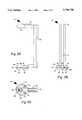
- FIG. 2Ais a first side view of the pivotable C-bracket included in the instrument of FIG. 1;
- FIG. 2Bis a second side view orthogonal to the first side view of the pivotable C-bracket included in the instrument of FIG. 1;
- FIG. 2Cis a bottom view of the pivotable C-bracket included in the instrument of FIG. 1.
- FIG. 1illustrates a survey instrument embodiment of the present invention, referred to herein by the general reference numeral 10.
- a global position system (GPS) receiver antenna 12is provided to receive L-band microwave radio transmissions from orbiting GPS satellites.
- Antenna 12is preferably a microwave patch antenna that includes a low noise amplifier (LNA).
- LNAlow noise amplifier
- the antenna and LNA 12are connected to a survey-quality satellite positioning system receiver and computer, e.g., SITE SURVEYORTM and TRIMTALKTM products marketed by Trimble Navigation Limited (Sunnyvale, Calif.).
- the antenna 12has an orientation direction 14 that can be matched with the orientation directions of other GPS antennas in a survey system to maximize performance and increase accuracy.
- the antenna 12has an electrical center that is intersected by an axis 18.
- the antenna 12mounts to a bracket 20 with a bolt hole 22 provided on an upper arm 24.
- the bracket 20includes a ring bearing 26 attached to a tribrach receptacle 28 that allows the bracket 20 to freely rotate 360° around the axis 18.
- the tribrach receptacle 28includes a set of three pin holes 30 that include locking blades that clamp any matching inserted pins.
- the tribrach receptacle 28is fixed to a tribrach plug 32 which includes a set of three locking pins 34.
- a central hole 36clear through the tribrach receptacle 28 and plug 32 allows for the use of an optical plumb along a sightline 38.
- the axis 18, the sightline 38, and the rotation of the ring bearing 26are all coaxial.
- the tribrach plug 32can be detached from, and locked into, a matching receptacle 40 that is mounted to a tripod 42 with a set of three legs 44.
- a set of three pin holes 46exactly match the pins 34.
- a hole 48continues a clear line of sight for sightline 38 to a survey point on the ground over which the tripod 42 is positioned.
- An optical survey instrument 50e.g., a theodolite, electronic distance meter (EDM) or total station, is pivotably mounted within the volume swept by the bracket 20.
- the optical survey instrument 50may comprise a commercial survey instrument product as marketed by PTS series by Pentax (Englewood, Colo.), TOP GUN total stations and DTM-700 series field stations by Nikon (Japan), ELTA 50 routine total stations by Zeiss (Thornwood, N.Y.), GTS-200/500/700 series by Topcon (Paramus, N.J.), POWERSET by Sokkia (Japan), etc.
- the optical survey instrument 50 and the pivot bracket 20each are independently free to turn 360° on the same axis 18.
- the body of the pivot bracket 20is preferably rotated by the intended user to any position that does not optically interfere with the optical survey instrument 50.
- the body of the pivot bracket 20may also be rotated by the user to a position in which orientation direction 14 is favorable for overall GPS accuracy.
- the electrical center of the antenna 12is positioned to be intersected by the axis 18, therefore the rotation of the pivot bracket 20 has little or no effect on the X, Y, Z electronic position of the antenna 12.
- FIGS. 2A, 2B and 2Cshow the pivot bracket 20 includes top end 24 for mounting the antenna and LNA 12, body 20 and bottom ring 26.
- the top end 24includes slot 22 that provides a modest amount of freedom in the exact positioning of the antenna.
- the bottom ring bearing 26, tribrach receptacle 28, tribrach plug 32, pin holes 30 and locking pins 34are configured to rotate with a minimum of wobble.
- the bottom ring 26is dimensioned to fit in between commercially available optical survey instruments designed for tribrach mounting and the corresponding tribrach mount.
- the bottom ring 26is preferably clamped between the optical survey instrument 50 and the level base 42 in a manner that allows the optical survey instrument 50 to be directly attached to the level base 42, e.g., with or without the pivot bracket 20 and antenna and LNA 12.
- the top end 24provides a surface that is perpendicular to the axis 18 for mounting a hemispherical response antenna, such as patch antenna 12.
- the receiving hemisphere of the antenna's responseis preferably oriented during use to receive signals from any orbiting GPS satellite visible between the horizons of the four points of the compass.
Landscapes
- Position Fixing By Use Of Radio Waves (AREA)
Abstract
Description
Claims (8)
Priority Applications (1)
| Application Number | Priority Date | Filing Date | Title |
|---|---|---|---|
| US08/654,040US5760748A (en) | 1996-05-28 | 1996-05-28 | Pivoting support bracket to mount a GPS antenna above a theodolite or a total station mounted on a tripod |
Applications Claiming Priority (1)
| Application Number | Priority Date | Filing Date | Title |
|---|---|---|---|
| US08/654,040US5760748A (en) | 1996-05-28 | 1996-05-28 | Pivoting support bracket to mount a GPS antenna above a theodolite or a total station mounted on a tripod |
Publications (1)
| Publication Number | Publication Date |
|---|---|
| US5760748Atrue US5760748A (en) | 1998-06-02 |
Family
ID=24623233
Family Applications (1)
| Application Number | Title | Priority Date | Filing Date |
|---|---|---|---|
| US08/654,040Expired - Fee RelatedUS5760748A (en) | 1996-05-28 | 1996-05-28 | Pivoting support bracket to mount a GPS antenna above a theodolite or a total station mounted on a tripod |
Country Status (1)
| Country | Link |
|---|---|
| US (1) | US5760748A (en) |
Cited By (31)
| Publication number | Priority date | Publication date | Assignee | Title |
|---|---|---|---|---|
| WO1999031516A1 (en)* | 1997-12-12 | 1999-06-24 | Laser Atlanta | Speed and position measurement system |
| US6407709B1 (en) | 1999-07-16 | 2002-06-18 | Garmin Corporation | Mounting device with integrated antenna |
| US6425186B1 (en) | 1999-03-12 | 2002-07-30 | Michael L. Oliver | Apparatus and method of surveying |
| USD464250S1 (en) | 2001-04-11 | 2002-10-15 | Trimble Navigation Limited | Bracket for coupling a global positioning system related device to a pole |
| US20030071762A1 (en)* | 2001-10-12 | 2003-04-17 | Tom Tulloch | Method of and apparatus for antenna alignment |
| US20040222340A1 (en)* | 2003-03-28 | 2004-11-11 | Richardson Paul William | Camera mount |
| US6874239B1 (en) | 2004-01-06 | 2005-04-05 | Troy White | Self-holding and self-leveling device for survey range pole and method of use |
| US7062305B1 (en)* | 2000-09-15 | 2006-06-13 | Trimble Navigation Limited | Location identifying apparatus and method of identifying the location of a user |
| EP1686350A1 (en)* | 2005-01-26 | 2006-08-02 | Leica Geosystems AG | Modularly expandable geodetic total station |
| US20060214865A1 (en)* | 2005-03-23 | 2006-09-28 | Andrew Corporation | Antenna Mount With Fine Adjustment Cam |
| US20060238492A1 (en)* | 2005-04-21 | 2006-10-26 | Fouquet Julie E | position determination utilizing a cordless device |
| US20070063911A1 (en)* | 2003-06-16 | 2007-03-22 | Davidson D | Cellular antenna and systems and methods therefor |
| US20070109527A1 (en)* | 2005-11-14 | 2007-05-17 | Wenstrand John S | System and method for generating position information |
| US20080099645A1 (en)* | 2006-11-01 | 2008-05-01 | Joseph Reichley | Golf cart mounted range finder assembly |
| KR100841534B1 (en) | 2007-01-03 | 2008-06-25 | 권혁숙 | Mobile wireless repeater |
| EP1854171A4 (en)* | 2005-02-14 | 2008-11-12 | Christian Boucher | Antenna alignment system and method |
| US20090061941A1 (en)* | 2006-03-17 | 2009-03-05 | Steve Clark | Telecommunications antenna monitoring system |
| US7611105B1 (en) | 2006-02-08 | 2009-11-03 | Kenneth Carazo | Corner prism pole and stand |
| US7908080B2 (en) | 2004-12-31 | 2011-03-15 | Google Inc. | Transportation routing |
| CN102521481A (en)* | 2011-11-16 | 2012-06-27 | 中国民航大学 | Vehicular airport clearance dynamic collection and management system as well as control method and airport clearance evaluation method thereof |
| WO2014036774A1 (en)* | 2012-09-06 | 2014-03-13 | 付建国 | Interconnecting-type multifunctional positioning measuring instrument |
| USD730946S1 (en) | 2014-03-05 | 2015-06-02 | Franklin B White | Mount for an excavation control unit |
| USD735595S1 (en) | 2014-04-02 | 2015-08-04 | Franklin B White | Support for GPS apparatus |
| US20150240988A1 (en)* | 2014-02-08 | 2015-08-27 | Franklin B. White | Theft resistant upstanding mount for temporary positioning of costly equipment at unattended outdoor locations |
| US20150292226A1 (en)* | 2014-02-08 | 2015-10-15 | Franklin B. White | Theft resistant upstanding mount for temporary positioning of costly equipment at unattended outdoor locations |
| US20160240910A1 (en)* | 2015-02-18 | 2016-08-18 | Commscope Technologies Llc | Antenna azimuth alignment monitor |
| WO2018109440A1 (en)* | 2016-12-13 | 2018-06-21 | Bae Systems Plc | Antenna arrangement |
| EP3352295A1 (en)* | 2017-01-18 | 2018-07-25 | BAE SYSTEMS plc | Antenna arrangement |
| WO2019028870A1 (en)* | 2017-08-11 | 2019-02-14 | 深圳市汇顶科技股份有限公司 | Test auxiliary device |
| CN112665564A (en)* | 2021-01-19 | 2021-04-16 | 四川省核工业地质局二八二大队 | Portable mapping device for geological mineral exploration |
| CN114211429A (en)* | 2021-12-30 | 2022-03-22 | 武汉武船计量试验有限公司 | Clamping tool |
Citations (12)
| Publication number | Priority date | Publication date | Assignee | Title |
|---|---|---|---|---|
| US2475746A (en)* | 1947-01-25 | 1949-07-12 | Kenyon Gyro & Electronics Corp | Radar antenna stabilizer |
| US2827629A (en)* | 1954-04-08 | 1958-03-18 | Raytheon Mfg Co | Antenna supporting structure and method of assembly |
| US4037229A (en)* | 1976-02-09 | 1977-07-19 | Dunk Thomas H | Antenna mount |
| US4290574A (en)* | 1980-06-02 | 1981-09-22 | Archibald John H | Kinematic restraint |
| JPS58101506A (en)* | 1981-12-14 | 1983-06-16 | Nippon Telegr & Teleph Corp <Ntt> | Simple compensator for shaking for mobile body mounting device |
| US5077557A (en)* | 1988-07-06 | 1991-12-31 | Wild Leitz Ag | Surveying instrument with receiver for satellite position-measuring system and method of operation |
| US5170197A (en)* | 1990-03-21 | 1992-12-08 | Sachtler Ag Kommunikationstechnik | Panning head, with a torque sensor |
| US5212493A (en)* | 1989-02-17 | 1993-05-18 | Thomson-Lgt Laboratoire General Des Telecomm. | Antenna system for reception from direct broadcasting satellites |
| US5233357A (en)* | 1988-07-06 | 1993-08-03 | Wild Leitz Ag | Surveying system including an electro-optic total station and a portable receiving apparatus comprising a satellite position-measuring system |
| US5419521A (en)* | 1993-04-15 | 1995-05-30 | Matthews; Robert J. | Three-axis pedestal |
| US5453756A (en)* | 1994-01-21 | 1995-09-26 | Lowrey; Larry | Antenna mounting apparatus |
| US5614918A (en)* | 1994-06-21 | 1997-03-25 | The United States Of America As Represented By The Administrator Of The National Aeronautics And Space Administration | Global positioning system antenna fixed height tripod adapter |
- 1996
- 1996-05-28USUS08/654,040patent/US5760748A/ennot_activeExpired - Fee Related
Patent Citations (12)
| Publication number | Priority date | Publication date | Assignee | Title |
|---|---|---|---|---|
| US2475746A (en)* | 1947-01-25 | 1949-07-12 | Kenyon Gyro & Electronics Corp | Radar antenna stabilizer |
| US2827629A (en)* | 1954-04-08 | 1958-03-18 | Raytheon Mfg Co | Antenna supporting structure and method of assembly |
| US4037229A (en)* | 1976-02-09 | 1977-07-19 | Dunk Thomas H | Antenna mount |
| US4290574A (en)* | 1980-06-02 | 1981-09-22 | Archibald John H | Kinematic restraint |
| JPS58101506A (en)* | 1981-12-14 | 1983-06-16 | Nippon Telegr & Teleph Corp <Ntt> | Simple compensator for shaking for mobile body mounting device |
| US5077557A (en)* | 1988-07-06 | 1991-12-31 | Wild Leitz Ag | Surveying instrument with receiver for satellite position-measuring system and method of operation |
| US5233357A (en)* | 1988-07-06 | 1993-08-03 | Wild Leitz Ag | Surveying system including an electro-optic total station and a portable receiving apparatus comprising a satellite position-measuring system |
| US5212493A (en)* | 1989-02-17 | 1993-05-18 | Thomson-Lgt Laboratoire General Des Telecomm. | Antenna system for reception from direct broadcasting satellites |
| US5170197A (en)* | 1990-03-21 | 1992-12-08 | Sachtler Ag Kommunikationstechnik | Panning head, with a torque sensor |
| US5419521A (en)* | 1993-04-15 | 1995-05-30 | Matthews; Robert J. | Three-axis pedestal |
| US5453756A (en)* | 1994-01-21 | 1995-09-26 | Lowrey; Larry | Antenna mounting apparatus |
| US5614918A (en)* | 1994-06-21 | 1997-03-25 | The United States Of America As Represented By The Administrator Of The National Aeronautics And Space Administration | Global positioning system antenna fixed height tripod adapter |
Cited By (55)
| Publication number | Priority date | Publication date | Assignee | Title |
|---|---|---|---|---|
| US6108071A (en)* | 1997-12-12 | 2000-08-22 | Laser Atlanta | Speed and position measurement system |
| WO1999031516A1 (en)* | 1997-12-12 | 1999-06-24 | Laser Atlanta | Speed and position measurement system |
| US6425186B1 (en) | 1999-03-12 | 2002-07-30 | Michael L. Oliver | Apparatus and method of surveying |
| US6407709B1 (en) | 1999-07-16 | 2002-06-18 | Garmin Corporation | Mounting device with integrated antenna |
| US7062305B1 (en)* | 2000-09-15 | 2006-06-13 | Trimble Navigation Limited | Location identifying apparatus and method of identifying the location of a user |
| USD464250S1 (en) | 2001-04-11 | 2002-10-15 | Trimble Navigation Limited | Bracket for coupling a global positioning system related device to a pole |
| US20030071762A1 (en)* | 2001-10-12 | 2003-04-17 | Tom Tulloch | Method of and apparatus for antenna alignment |
| US6657598B2 (en)* | 2001-10-12 | 2003-12-02 | Andrew Corporation | Method of and apparatus for antenna alignment |
| US20040222340A1 (en)* | 2003-03-28 | 2004-11-11 | Richardson Paul William | Camera mount |
| US20070063911A1 (en)* | 2003-06-16 | 2007-03-22 | Davidson D | Cellular antenna and systems and methods therefor |
| US8018390B2 (en) | 2003-06-16 | 2011-09-13 | Andrew Llc | Cellular antenna and systems and methods therefor |
| US6874239B1 (en) | 2004-01-06 | 2005-04-05 | Troy White | Self-holding and self-leveling device for survey range pole and method of use |
| US9709415B2 (en) | 2004-12-31 | 2017-07-18 | Google Inc. | Transportation routing |
| US8798917B2 (en) | 2004-12-31 | 2014-08-05 | Google Inc. | Transportation routing |
| US9945686B2 (en) | 2004-12-31 | 2018-04-17 | Google Llc | Transportation routing |
| US7908080B2 (en) | 2004-12-31 | 2011-03-15 | Google Inc. | Transportation routing |
| US9778055B2 (en) | 2004-12-31 | 2017-10-03 | Google Inc. | Transportation routing |
| US8606514B2 (en) | 2004-12-31 | 2013-12-10 | Google Inc. | Transportation routing |
| US11092455B2 (en) | 2004-12-31 | 2021-08-17 | Google Llc | Transportation routing |
| WO2006079604A1 (en)* | 2005-01-26 | 2006-08-03 | Leica Geosystems Ag | Geodetic total station that can be extended in a modular manner |
| US20080094606A1 (en)* | 2005-01-26 | 2008-04-24 | Leica Geosystems Ag | Geodetic Total Station Which Can Be Extended In A Modular Manner |
| CN100533061C (en)* | 2005-01-26 | 2009-08-26 | 莱卡地球系统公开股份有限公司 | Geodetic central station which can be extended in a modular manner |
| US7583373B2 (en) | 2005-01-26 | 2009-09-01 | Leica Geosystems Ag | Geodetic total station which can be extended in a modular manner |
| EP1686350A1 (en)* | 2005-01-26 | 2006-08-02 | Leica Geosystems AG | Modularly expandable geodetic total station |
| EP1854171A4 (en)* | 2005-02-14 | 2008-11-12 | Christian Boucher | Antenna alignment system and method |
| US7439930B2 (en)* | 2005-03-23 | 2008-10-21 | Asc Signal Corporation | Antenna mount with fine adjustment cam |
| US20060214865A1 (en)* | 2005-03-23 | 2006-09-28 | Andrew Corporation | Antenna Mount With Fine Adjustment Cam |
| US20100001950A1 (en)* | 2005-04-21 | 2010-01-07 | Avago Technologies Ecbu Ip (Singapore) Pte. Ltd. | Position determination utilizing a cordless device |
| US20060238499A1 (en)* | 2005-04-21 | 2006-10-26 | Wenstrand John S | Powerless signal generator for use in conjunction with a powerless position determination device |
| US7609249B2 (en) | 2005-04-21 | 2009-10-27 | Avago Technologies Ecbu Ip (Singapore) Pte. Ltd. | Position determination utilizing a cordless device |
| US8384663B2 (en) | 2005-04-21 | 2013-02-26 | Avago Technologies General Ip (Singapore) Pte. Ltd. | Position determination utilizing a cordless device |
| US7812816B2 (en) | 2005-04-21 | 2010-10-12 | Avago Technologies Ecbu Ip (Singapore) Pte. Ltd. | Powerless signal generation for use in conjunction with a powerless position determination device |
| US20060238492A1 (en)* | 2005-04-21 | 2006-10-26 | Fouquet Julie E | position determination utilizing a cordless device |
| US20070109527A1 (en)* | 2005-11-14 | 2007-05-17 | Wenstrand John S | System and method for generating position information |
| US7611105B1 (en) | 2006-02-08 | 2009-11-03 | Kenneth Carazo | Corner prism pole and stand |
| US20090061941A1 (en)* | 2006-03-17 | 2009-03-05 | Steve Clark | Telecommunications antenna monitoring system |
| US20080099645A1 (en)* | 2006-11-01 | 2008-05-01 | Joseph Reichley | Golf cart mounted range finder assembly |
| KR100841534B1 (en) | 2007-01-03 | 2008-06-25 | 권혁숙 | Mobile wireless repeater |
| CN102521481A (en)* | 2011-11-16 | 2012-06-27 | 中国民航大学 | Vehicular airport clearance dynamic collection and management system as well as control method and airport clearance evaluation method thereof |
| CN102521481B (en)* | 2011-11-16 | 2014-11-19 | 中国民航大学 | A vehicle-mounted airport headroom dynamic acquisition management system and control evaluation method |
| WO2014036774A1 (en)* | 2012-09-06 | 2014-03-13 | 付建国 | Interconnecting-type multifunctional positioning measuring instrument |
| US20150292226A1 (en)* | 2014-02-08 | 2015-10-15 | Franklin B. White | Theft resistant upstanding mount for temporary positioning of costly equipment at unattended outdoor locations |
| US9637942B2 (en)* | 2014-02-08 | 2017-05-02 | Franklin B. White | Theft resistant upstanding mount for temporary positioning of costly equipment at unattended outdoor locations |
| US20150240988A1 (en)* | 2014-02-08 | 2015-08-27 | Franklin B. White | Theft resistant upstanding mount for temporary positioning of costly equipment at unattended outdoor locations |
| US9803794B2 (en)* | 2014-02-08 | 2017-10-31 | Franklin B White | Theft resistant upstanding mount for temporary support of costly equipment likely to be a target for theft |
| US9534731B2 (en)* | 2014-02-08 | 2017-01-03 | Franklin B White | Theft resistant upstanding mount for temporary positioning of costly equipment at unattended outdoor locations |
| USD730946S1 (en) | 2014-03-05 | 2015-06-02 | Franklin B White | Mount for an excavation control unit |
| USD735595S1 (en) | 2014-04-02 | 2015-08-04 | Franklin B White | Support for GPS apparatus |
| US20160240910A1 (en)* | 2015-02-18 | 2016-08-18 | Commscope Technologies Llc | Antenna azimuth alignment monitor |
| WO2018109440A1 (en)* | 2016-12-13 | 2018-06-21 | Bae Systems Plc | Antenna arrangement |
| EP3352295A1 (en)* | 2017-01-18 | 2018-07-25 | BAE SYSTEMS plc | Antenna arrangement |
| WO2019028870A1 (en)* | 2017-08-11 | 2019-02-14 | 深圳市汇顶科技股份有限公司 | Test auxiliary device |
| CN112665564A (en)* | 2021-01-19 | 2021-04-16 | 四川省核工业地质局二八二大队 | Portable mapping device for geological mineral exploration |
| CN112665564B (en)* | 2021-01-19 | 2022-12-20 | 四川省核工业地质局二八二大队 | A portable surveying and mapping device for geological and mineral prospecting |
| CN114211429A (en)* | 2021-12-30 | 2022-03-22 | 武汉武船计量试验有限公司 | Clamping tool |
Similar Documents
| Publication | Publication Date | Title |
|---|---|---|
| US5760748A (en) | Pivoting support bracket to mount a GPS antenna above a theodolite or a total station mounted on a tripod | |
| US5077557A (en) | Surveying instrument with receiver for satellite position-measuring system and method of operation | |
| US6369755B1 (en) | Integrated SATPS total survey station | |
| US5471218A (en) | Integrated terrestrial survey and satellite positioning system | |
| US7764365B2 (en) | Combination laser detector and global navigation satellite receiver system | |
| US5379045A (en) | SATPS mapping with angle orientation calibrator | |
| EP1774257B1 (en) | Combination laser system and global navigation satellite system | |
| US6052083A (en) | Method and apparatus for position identification | |
| US8705022B2 (en) | Navigation system using both GPS and laser reference | |
| CA2596593C (en) | Antenna alignment system and method | |
| US9091540B2 (en) | Geodetic surveying system and method for operating a geodetic surveying system | |
| US5760909A (en) | Integrated apparatus and method for EDM and GPS surveying | |
| US6732051B1 (en) | Seamless surveying system | |
| US5022751A (en) | Portable localizer siting system | |
| US6453569B1 (en) | Surveying instrument and plumbing device for plumbing surveying instrument | |
| US20020008870A1 (en) | Low cost 2D position measurement system and method | |
| US5835069A (en) | GPS antennas and receivers configured as handles for a surveyor's optical total station | |
| WO2003019223A2 (en) | Methods and systems for improvement of measurement efficiency in surveying | |
| US5276972A (en) | Satellite locator | |
| JPS5912966B2 (en) | Method and device for automatically leveling a goniometer | |
| US6014109A (en) | Offset-antenna total station | |
| RU2522784C1 (en) | Laser pointer/range-finder | |
| US5046259A (en) | Underwater measuring systems and methods | |
| US6526667B1 (en) | Satellite spacecraft targeting device and method | |
| EP1726915A1 (en) | Active surveying pole |
Legal Events
| Date | Code | Title | Description |
|---|---|---|---|
| AS | Assignment | Owner name:TRIMBLE NAVIGATION LIMITED, CALIFORNIA Free format text:ASSIGNMENT OF ASSIGNORS INTEREST;ASSIGNOR:BECKINGHAM, MICHAEL;REEL/FRAME:008017/0774 Effective date:19960523 | |
| AS | Assignment | Owner name:ABN AMRO BANK N.V., AS AGENT, ILLINOIS Free format text:SECURITY AGREEMENT;ASSIGNOR:TRIMBLE NAVIGATION LIMITED;REEL/FRAME:010996/0643 Effective date:20000714 | |
| FPAY | Fee payment | Year of fee payment:4 | |
| AS | Assignment | Owner name:TRIMBLE NAVIGATION LIMITED, CALIFORNIA Free format text:RELEASE OF SECURITY INTEREST;ASSIGNOR:ABN AMRO BANK N.V.;REEL/FRAME:016345/0177 Effective date:20050620 | |
| FEPP | Fee payment procedure | Free format text:PAYOR NUMBER ASSIGNED (ORIGINAL EVENT CODE: ASPN); ENTITY STATUS OF PATENT OWNER: LARGE ENTITY | |
| REMI | Maintenance fee reminder mailed | ||
| FPAY | Fee payment | Year of fee payment:8 | |
| SULP | Surcharge for late payment | Year of fee payment:7 | |
| REMI | Maintenance fee reminder mailed | ||
| LAPS | Lapse for failure to pay maintenance fees | ||
| STCH | Information on status: patent discontinuation | Free format text:PATENT EXPIRED DUE TO NONPAYMENT OF MAINTENANCE FEES UNDER 37 CFR 1.362 | |
| FP | Lapsed due to failure to pay maintenance fee | Effective date:20100602 |