US5760588A - Dual rate thermochromic battery tester - Google Patents
Dual rate thermochromic battery testerDownload PDFInfo
- Publication number
- US5760588A US5760588AUS08/900,438US90043897AUS5760588AUS 5760588 AUS5760588 AUS 5760588AUS 90043897 AUS90043897 AUS 90043897AUS 5760588 AUS5760588 AUS 5760588A
- Authority
- US
- United States
- Prior art keywords
- battery
- conductive element
- tester
- resistance
- label
- Prior art date
- Legal status (The legal status is an assumption and is not a legal conclusion. Google has not performed a legal analysis and makes no representation as to the accuracy of the status listed.)
- Expired - Lifetime
Links
Images


Classifications
- G—PHYSICS
- G01—MEASURING; TESTING
- G01D—MEASURING NOT SPECIALLY ADAPTED FOR A SPECIFIC VARIABLE; ARRANGEMENTS FOR MEASURING TWO OR MORE VARIABLES NOT COVERED IN A SINGLE OTHER SUBCLASS; TARIFF METERING APPARATUS; MEASURING OR TESTING NOT OTHERWISE PROVIDED FOR
- G01D7/00—Indicating measured values
- G01D7/005—Indication of measured value by colour change
- H—ELECTRICITY
- H01—ELECTRIC ELEMENTS
- H01M—PROCESSES OR MEANS, e.g. BATTERIES, FOR THE DIRECT CONVERSION OF CHEMICAL ENERGY INTO ELECTRICAL ENERGY
- H01M10/00—Secondary cells; Manufacture thereof
- H01M10/42—Methods or arrangements for servicing or maintenance of secondary cells or secondary half-cells
- H01M10/48—Accumulators combined with arrangements for measuring, testing or indicating the condition of cells, e.g. the level or density of the electrolyte
- H01M10/488—Cells or batteries combined with indicating means for external visualization of the condition, e.g. by change of colour or of light density
- H—ELECTRICITY
- H01—ELECTRIC ELEMENTS
- H01M—PROCESSES OR MEANS, e.g. BATTERIES, FOR THE DIRECT CONVERSION OF CHEMICAL ENERGY INTO ELECTRICAL ENERGY
- H01M6/00—Primary cells; Manufacture thereof
- H01M6/50—Methods or arrangements for servicing or maintenance, e.g. for maintaining operating temperature
- H01M6/5044—Cells or batteries structurally combined with cell condition indicating means
- H01M6/505—Cells combined with indicating means for external visualization of the condition, e.g. by change of colour or of light intensity
- G—PHYSICS
- G01—MEASURING; TESTING
- G01R—MEASURING ELECTRIC VARIABLES; MEASURING MAGNETIC VARIABLES
- G01R31/00—Arrangements for testing electric properties; Arrangements for locating electric faults; Arrangements for electrical testing characterised by what is being tested not provided for elsewhere
- G01R31/36—Arrangements for testing, measuring or monitoring the electrical condition of accumulators or electric batteries, e.g. capacity or state of charge [SoC]
- G01R31/385—Arrangements for measuring battery or accumulator variables
- H—ELECTRICITY
- H01—ELECTRIC ELEMENTS
- H01M—PROCESSES OR MEANS, e.g. BATTERIES, FOR THE DIRECT CONVERSION OF CHEMICAL ENERGY INTO ELECTRICAL ENERGY
- H01M2200/00—Safety devices for primary or secondary batteries
- H01M2200/10—Temperature sensitive devices
- Y—GENERAL TAGGING OF NEW TECHNOLOGICAL DEVELOPMENTS; GENERAL TAGGING OF CROSS-SECTIONAL TECHNOLOGIES SPANNING OVER SEVERAL SECTIONS OF THE IPC; TECHNICAL SUBJECTS COVERED BY FORMER USPC CROSS-REFERENCE ART COLLECTIONS [XRACs] AND DIGESTS
- Y02—TECHNOLOGIES OR APPLICATIONS FOR MITIGATION OR ADAPTATION AGAINST CLIMATE CHANGE
- Y02E—REDUCTION OF GREENHOUSE GAS [GHG] EMISSIONS, RELATED TO ENERGY GENERATION, TRANSMISSION OR DISTRIBUTION
- Y02E60/00—Enabling technologies; Technologies with a potential or indirect contribution to GHG emissions mitigation
- Y02E60/10—Energy storage using batteries
Definitions
- the present inventiongenerally pertains to battery testers, and more particularly, relates to on-label thermochromic battery testers.
- Batteriesare often stored before being used. Batteries are typically stored by retailers before being sold. After purchase by a consumer, such batteries are again typically stored for some period of time prior to use. If the period of storage is significant, batteries may self-discharge. Therefore, it is desirable to utilize a battery tester to determine if a battery has sufficient charge to operate a desired device.
- Thermochromic battery testerstypically include a conductive element that is selectively connected between opposite terminals of the battery.
- the conductive elementincludes a switch pad at one or both ends that is pressed by the user to connect the conductive element across the terminals of the battery.
- the conductive elementWhen the conductive element is connected between the battery terminals, it generates heat as a function of its resistivity and the current flowing from the battery. The level of current produced by the battery is one indicator of the remaining battery capacity.
- Thermochromic testersfurther include a thermochromic layer, which changes its color or visual appearance as a function of the heat generated by the conductive element.
- a thermochromic on-label battery testermay provide an indication of the discharge level of the battery.
- a thermochromic material that changes between opaque and transparent statesmay be utilized to expose indicia underlying the thermochromic layer indicating that the battery is still "good” when a sufficient level of current is output from the battery.
- Batteriesare used in a variety of applications having widely varying power consumption rates. For example, batteries used to power a camera flash are discharged at a much higher rate than batteries used to power radios, clocks, and flashlights. For those high-rate uses, a higher level of remaining battery capacity is required for the battery to continue to power a high-rate device. Thus, a battery will have been considered to have been fully discharged for such high-rate uses even though the battery would still be considered to be "good" for use in a clock or radio. Thus, a battery tester circuit that is calibrated for a single rate of discharge may not accurately reflect the relative discharge level for use in other applications.
- the on-label battery testeris calibrated for high-rate applications (i.e., constructed such that it indicates that the battery is no longer "good” then the battery capacity is not sufficient to recharge a photo-flash unit), then batteries that are still suitable for use in low drain devices, will be needlessly discarded.
- the battery testeris calibrated for low-drain devices (i.e., constructed to accurately indicate that a battery is no longer "good” when the cell capacity is insufficient to power a radio or clock)
- the indicatormay wrongfully suggest that the battery is still "good” when in fact it is not sufficiently “good” to power a high-rate device. This would result in a perception by the consumers that the battery testers are very inaccurate.
- thermochromic materials used in such on-label testerschange visual states through a range of predetermined temperatures.
- Fresh batterieshave a higher open circuit voltage and a lower internal resistance and therefore are capable of generating more heat and a greater temperature rise than batteries that have been discharged.
- thermochromic testersare capable of giving valid information about the state of charge of the battery provided that the battery is tested at the temperature used for calibration of the tester circuit. However, if the tester is used in a colder environment, more heat must be generated by the conductive element to change the visual state of the thermochromic material.
- thermochromic testershave printed instructions on the battery label to only test the battery at a specified ambient temperature, such as room temperature. Because users will often ignore such instructions and because it may not be possible or convenient for the user to allow the battery to warm up or cool down to the specified temperature, inaccurate discharge level readings are often obtained causing the user to either discard a good battery or to wrongfully believe that a battery is still "good” when it is in fact discharged. Therefore, there exists a need for an on-label thermochromic battery tester that will provide an accurate indication of whether the battery is good regardless of the ambient temperature in which the tester is used.
- an aspect of the inventionis to solve the above problems by providing an on-label thermochromic battery tester that provides an accurate indication of the discharge level of the battery regardless of the discharge rate of the device in which the battery is to be used.
- the battery tester of the present inventioncomprises a conductive heating element having one end including at least two switch pads for selective coupling of the conductive heating element to a second terminal of the battery. Each of the switch pads provides a different resistivity for the heating element when pressed, to thereby change the calibration of the tester for different discharge rates.
- the battery testerfurther includes discharge rate calibration indicia associated with each of the switch pads for indicating which switch pad to press for proper calibration at a relative rate of discharge.
- a further aspect of the present inventionis to provide a battery tester that not only provides the ability of the user to select the proper calibration for the intended rate of discharge but also provides an accurate indication of the discharge level of the battery regardless of the ambient temperature of the environment in which the battery tester is used.
- the battery tester of the present inventionfurther includes the conductive heating element having at least a portion thereof made of a variable resistivity material having a resistivity that changes in response to ambient temperature so as to compensate for varying ambient temperatures.
- the variable resistivity materialhas a resistivity that increases as ambient temperature increases.
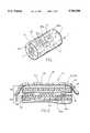
- FIG. 1is an illustration of a battery having a battery tester label in accordance with this invention disposed about the outer periphery of the battery;
- FIG. 2is a cross section of the battery tester label taken along plane II--II of FIG. 1;
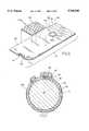
- FIG. 3is an exploded view of a subcomponent of the battery tester label, referred to herein as the tester device;
- FIG. 4is a top plan view of the inserted tester device
- FIG. 5is a bottom plan view of the inserted tester device, the cross-hatching indicating a layer of adhesive
- FIG. 6is an exploded view of another subcomponent of the battery tester label, referred to herein as the base layer;
- FIG. 7is a cross section of a battery and the battery tester label
- FIG. 8is an exploded view of the battery tester label
- FIG. 9is a top view of a conductive circuit constructed in accordance with a first variation of a second embodiment of the present invention.
- FIG. 10is a cross section of a conductive circuit shown in FIG. 9 taken along plane X--X;
- FIG. 11is a top view of a conductive circuit constructed in accordance with a second variation of the second embodiment of the present invention.
- FIG. 12is a cross section of the conductive circuit shown in FIG. 11 taken along plane XII--XII;
- FIG. 13is a top view of a conductive circuit constructed in accordance with a third variation of a second embodiment of the present invention.
- FIG. 14is a cross section of a conductive circuit shown in FIG. 13 taken along plane XIV--XIV;
- FIG. 15is a top view of a conductive circuit constructed in accordance with a fourth variation of the second embodiment of the present invention.
- FIG. 16is a cross section of the conductive circuit shown in FIG. 15 taken along plane XVI--XVI.
- FIG. 1illustrates a battery and label assembly 1 comprising a battery can 2, a negative terminal 4, and a positive terminal 6.
- Can 2may be in electrical contact with positive terminal 6.
- Battery 1may include one or more electrochemical cells, which may be primary cells or secondary cells.
- Extending around and attached to the periphery of can 2is a label 10 including a battery tester device 15, which is the subject of this invention. As shown, tester device 15 comprises switches 64, 65a, and 65b which activate tester 15 to indicate the state of charge of the battery by exposing indicia 23 or producing some other visual indication.
- tester device 15generally comprises a laminate or layered assembly having a substrate layer 20, an elongated electrically conductive circuit 18 disposed on a first face of substrate 20, and a pressure-sensitive adhesive 16 disposed on portions of both conductive circuit 18 and the first face of substrate 20.
- Adhesive 16indicated by cross-hatching in FIG. 5, is preferably applied over conductive layer 18 in the pattern illustrated. Adhesive 16 is omitted from those areas which will overlie printed insulation 44 and switch pads 42, 42a, and 42b (FIGS. 6 and 8) when the tester 15 is affixed to a base laminate 30. This adhesive pattern retards moisture from migrating to switch segments 60, 61a, and 61b of conductive circuit 18 while not interfering with the function of either the switches or the insulation discussed below.
- Tester device 15further comprises one or more graphic layers 22, preferably of decorative ink, and indicia 23 that are disposed on a second face of substrate 20 opposite the face containing conductive circuit 18.
- Tester device 15also comprises a layer of a temperature sensitive (i.e., thermochromic) indicating material 24 that is deposited upon the second face of substrate 20, preferably upon graphic layers 22 and indicia 23.
- a layer of a clear protective coating(not shown) is preferably deposited over indicator layer 24 and optionally upon graphic layers 22 and other exposed regions of the second face of substrate 20.
- the resistance of conductive circuit 18 as presented between the two contacted terminals of the batterymay be selectively varied.
- pressing switch 65awould present a lower resistance than if switch 65b were pressed.
- Battery tester device 15also preferably includes indicia 90a and 90b printed on the outermost layer of device 15 in association with each of switches 65a and 65b in order to indicate which switch should be pressed for high- or low-rate applications. Because the high-rate discharge application requires greater battery capacity to be considered "good,” the resistance of conductive circuit 18 must be greater than that for lower discharge rate applications for proper calibration.
- switch 65awould be used for low-rate devices such as a radio, and switch 65b would be used for high-rate devices such as a photo-flash.
- the second switchmay be provided by adding a little additional conductive ink and punching one more hole through the battery label to allow for contact.
- the additional feature of providing for two separate calibrations for different discharge ratesmay be accomplished at very low cost.
- conductive circuit 18, which serves as a heating elementis printed in the pattern as illustrated in FIGS. 3, 5, and 8 using a material having a resistivity that varies as a function of temperature.
- conductive materialspreferably have a positive temperature coefficient (PTC) of resistance causing the resistance of conductive circuit 18 to increase with the ambient temperature of the environment in which the tester may be used.
- PTCpositive temperature coefficient
- Thermistor-type solid state materialsmay also be used. Given the dimensions typically used for the type of conductive circuit 18 shown in the drawings, for a temperature range of 10° C. to 40° C. (50° F. to 104° F.), the resistivity of conductive circuit 18 will preferably change by a factor of 25.
- carbon-based compositionsexist that may be employed for this purpose to achieve the objectives of the present invention.
- examples of such carbon-based compositionsinclude ethylene-ethylacrylate copolymer; polyolefins and polyolefin-paraffin mixtures, e.g., polyethylene; polyethylene oxide; and nylon 66.
- An advantage in forming conductive circuit 18 entirely of a single variable resistance materialis that conductive circuit 18 may be produced using a single print station.
- a portion of conductive circuit 18is formed using a material having a non-variable resistivity and a portion made from a material having a variable resistivity.
- the portion of conductive circuit 18 that is made of a variable resistivity materialmay be electrically coupled in series with the other portion of conductive circuit 18 or in parallel, as described below,
- the material used to form the portion of non-variable resistivityis a silver ink and the material used to form the variable resistivity portion is one of the above carbon-based compositions.
- FIGS. 9-12show a conductive circuit of the second embodiment of the present invention with the portion of variable resistance coupled in series with the portion of non-variable resistance.
- a conductive circuit 18may be formed by printing the non-variable resistivity portion in essentially the same pattern as discussed above with respect to the first embodiment except that a conductive ink is used that has a constant resistivity, and a gap 82 is provided in the deposited layer to electrically isolate switch segments 60, 61a, and 61b. Subsequently, a layer 80 formed of a material having a variable resistivity is printed across gap 82 in contact with edges 84 and 86 of the first printed material that are adjacent gap 82.
- FIGS. 11 and 12An alternative method and construction for a series-coupled conductive circuit 18 according to the second embodiment is illustrated in FIGS. 11 and 12.
- contact portions 84 and 86 of the non-variable resistivity materialare overlapping with a layer 80 of variable resistivity material sandwiched therebetween.
- the total resistance appearing between switch segments 60, 61a, and 61bwill be equal to the sum of the resistance of the segments 60, 61a, and 61b and layer 80.
- This increase in resistancedecreases the current flowing through central portion 62 of conductive circuit 18 thereby resulting in less heat being generated by central portion 62 which underlies thermochromic layer 24.
- FIGS. 13-16illustrate the parallel connection approach to the second embodiment of the present invention.
- the layer 80 of variable resistivity materialin parallel with the portion of non-variable resistivity, the latter portion may be printed having first and second legs 88 and 89 extending perpendicularly from an axis between switch segments 60, 61a, and 61b while being provided with a gap 82 therebetween.
- a layer 80 of variable resistivity materialmay be printed across gap 82 in series with legs 88 and 89 and in parallel with at least a portion of the non-variable resistivity material of conductive circuit 18.
- An alternative constructionis shown in FIGS. 15 and 16 in which legs 88 and 89 overlap one another with layer 80 of variable resistivity material provided therebetween.
- the parallel connected variationeffectively increases the resistance of conductive circuit 18 in response to an increase in ambient temperature.
- the tester device 15, as shown in FIGS. 2-5 and 8,is preferably prepared as follows.
- a plastic filmis provided for substrate 20.
- FIG. 3illustrates substrate 20 as being transparent, substrate 20 could be formed from a wide variety of other materials including opaque and translucent materials.
- Conductive circuit 18is deposited on one face of substrate 20.
- Conductive circuit 18, having the properties discussed above,is preferably deposited in the form of a pattern comprising two distal regions and a medially disposed area 62 which undergoes an increase in temperature upon passage of electrical current.
- the pressure-sensitive adhesive material 16is deposited on at least portions of either or both conductive circuit 18 and a face of substrate 20.
- a silicone-coated release linersuch as a silicone-coated paper or plastic film (not shown), is applied onto the previously deposited pressure-sensitive adhesive 16 to facilitate handling and/or storage of tester device 15.
- Graphics and/or other labeling colors 22 in the form of a layer or layers of decorative ink and indicia 23are printed onto the opposite side of substrate 20 from that on which the conductive circuit 18 is positioned. It is preferred that indicia 23 be disposed directly above the area of controlled resistivity 62 of conductive circuit 18 located on the other side of substrate 20. Additional graphics are also preferably printed to designate switch regions 64, 65a, and 65b. If necessary, one or more curing operations may be performed to cure or partially cure the graphic or coloring layers.
- thermochromic ink or other indicator material 24is deposited onto substrate 20 such that it is situated directly above the area of controlled resistivity 62 of conductive circuit 18 and preferably over indicia 23.
- a clear protective coatingsuch as a varnish film, is then applied over and onto the indicator material, and optionally over the remaining regions of this side of substrate 20 to protect such regions from damage by subsequent manufacturing or storage operations.
- Each of the previously-described layers or elementspreferably have a thickness of from about 0.00005 inch to about 0.005 inch. The tester device, if necessary, can be cut to an appropriate size.
- base laminate 30is a laminate or layered structure comprising a substrate 34, with one face having a layer of pressure-sensitive adhesive 32 for subsequent contact with a battery, and another face having one or more layers as follows: a metallization layer 36; a primer and/or decorative layer 38; an electrical insulation layer 40; and a thermal insulation layer 44. Also residing proximate to the thermal insulation layer are one or more switch throw pads 42 described in greater detail below.
- Base laminate 30is preferably prepared as follows.
- a plastic filmis provided for the base layer substrate 34.
- the pressure-sensitive adhesive material 32is deposited upon the face of the base layer substrate 34 that will subsequently face and contact the battery can 2.
- a silicone release lineris applied on the pressure-sensitive adhesive to facilitate handling and other processing operations.
- On the opposite face of base layer substrate 34one or more graphic or labeling color layers are deposited, for instance, by printing.
- metallization layer 36is utilized to provide a decorative reflective layer. If a metallization layer is deposited, it will in most instances be necessary to deposit a receptive coating or primer layer 38 onto those regions of metallization layer 36 upon which other decorative layers are to be deposited.
- Primer layer 38may in itself be a decorative layer. It is also desirable to deposit a layer of electrical insulation 40 upon metallization layer 36 and/or primer layer 38 to prevent electrical contact, i.e., shorting, between layer 36 and the conductive circuit 18 of tester device 15 during assembly of label 10.
- Thermal insulation 44is positioned in an area of base layer substrate 34 that will be disposed beneath the indicator material 24 and the maximum resistance area 62 of conductive circuit 18 of the previously-described tester device 15. This thermal insulation reduces heat transfer from the area of controlled resistivity 62 of conductive circuit 18 to the battery. If such heat transfer is not controlled and the battery is permitted to act as a heat sink, the change in temperature at indicator material 24 may be insufficient to provide an accurate indication of the battery state of charge.
- Thermal insulation 44preferably comprises a plurality of apertures 46c which, when assembled into the laminate structure of the preferred label 10, provide air pockets which further thermally insulate the conductive circuit 18 from the battery.
- a larger region of air space or voidmay be formed to serve as insulation by depositing a suitable spacer material onto the base laminate 30.
- the preferred insulative patternis a series of islands printed onto laminate 30 in the manner shown in FIG. 1A of U.S. Pat. No. 5,389,458.
- Switch throw pads 42a and 42bare also formed surrounding a switch apertures 46a and 46b, respectively. This raised pad provides spacing between switch segments 61a and 61b of the conductive circuit 18 and battery can 2, and significantly minimizes the occurrence of accidental switch closure. Raised switch throw pads 42a and 42b are preferably formed by depositing or printing a dielectric ink or other suitable material. A second switch pad 42 may be formed proximate a switch aperture 47 as shown in FIGS. 6 and 8. This pad has not been found necessary for proper functioning of the tester.
- one or more cure stepsmay be utilized when depositing or printing any of the previously-described layers, particularly the decorative inks.
- Each of the previously-described layers or elementspreferably has a thickness from about 0.00005 inch to about 0.005 inch.
- Switch apertures 46a, 46b, and 47are preferably formed in base laminate 30 after printing thermal insulation 44 and switch throw pads 42, 42a, and 42b. Such apertures are preferably formed by suitable punching operations. Registry problems are minimized by printing what is to become switch pads 42a and 42b as a solid disk and thereafter punching apertures 46a and 46b centrally through this disk. Switch apertures are formed in the base laminate 30 so that when the previously-described inserted tester device 15 is combined with base laminate 30, switch apertures 46a, 46b, and 47 are located directly beneath the distal switch segments 60 and 61 of conductive circuit 18. The preferred geometry for such switch apertures is a notch 47 for the negative switch segment 64 and a circle 46a/46b for the positive switch segments 65a and b.
- the switches utilized in the battery tester labelare preferably membrane switches such that a switch segment 60, 61a, or 61b of conductive circuit 18 overlies apertures 46a, 46b, and 47 in base laminate 30. Apertures 46a, 46b, and 47 in base laminate 30 enable contact between conductive circuit 18 and either a battery terminal or can 2 on the other side of base laminate 30.
- a force to a switch segmentsuch as by applying finger or thumb pressure at switch segments 64, 65a, or 65b
- a portion of the switch segmentis pressed or deformed through the opening in base laminate 30 to contact the battery terminal or can 2.
- the portion of the switch segmentresiliently "springs" away from and, thus, out of electrical contact with the battery terminal or can 2. This configuration is referred to herein as "switchably connected.”
- a significant advantage provided by the present invention battery tester labelis the absence of electrically conductive layers or members to electrically connect and disconnect the tester, i.e., conductive circuit 18, to and from the battery. This is remarkable and of significant benefit particularly when manufacturing a battery tester label in large volumes and at a high rate.
- This advantage of eliminating otherwise necessary electrically conductive switching componentsis achieved in part by providing a first switch 64 which is disposed very near a battery terminal, such as negative terminal 4. Such close proximity eliminates the need for additional conductive elements to electrically connect an end of circuit 18 to the negative battery terminal. It is most preferred to fold or shrink the peripheral edge of label 10 over the battery end at which the negative terminal is disposed, as illustrated in FIG. 1.
- the tester device 15is combined with base laminate 30 as follows and as best shown in FIG. 8.
- the tester deviceis positioned onto or adjacent base laminate 30 so that switch segments 60, 61a, and 61b of conductive circuit 18 overlie switch apertures 46a, 46b, and 47, respectively.
- Tester device 15is oriented such that the layer of pressure-sensitive adhesive 16 (the release liner having been removed if previously applied) is facing base laminate 30.
- the two assembliesare securely attached to each other via adhesive 16, and form the preferred battery tester label 10 of the present invention.
- a clear laminating adhesive 52is deposited upon the outward facing surface of the resulting tester label as illustrated in FIG.
- a clear film 54such as polyvinyl chloride or polyester, is applied over the coating and the resulting assembly cured.
- a coating of adhesive 52 and film 54when applied onto the tester label, provide protection for the tester device and components thereof. It is most preferred that the transparent protective layer resulting from adhesive coating 52 and film 54 is deposited upon the battery tester label prior to application of the tester label to a battery.
- the resulting battery tester label 10is appropriately die cut to the size of the battery desired. Upon removal of excess trimmed label, a plurality of individual tester labels are left remaining on the release liner previously applied to substrate 34 of base laminate 30. The liner and label array may then be cut into strips and wound into a roll and stored for subsequent application to batteries.
- the substrate layer utilized for either or both the base layer substrate 34 and the tester device substrate 20can be made of any desired dielectric polymer material. It is preferable to use a dielectric polymer material that will shrink when assembled on a battery. Generally, polyvinyl resins, polyolefin resins, polyester resins and the like would be suitable. Specific examples include polyvinyl chloride, polyethylene and polypropylene. It is contemplated that substrate 20 could also be formed from other dielectric materials besides plastics such as paper or other cellulose-based materials.
- the thickness of the substrate layersis not particularly limited, but is preferably in the range of from about 0.0005 to about 0.005 inch, and most preferably from about 0.001 to about 0.003 inch.
- the previously-described indicator layer 24 in the inserted tester device 15comprises a thermally sensitive material for indicating the capacity of the battery.
- the preferred thermally sensitive materialschange color in response to a temperature change, which change is readily viewable by a consumer. Thus, the consumer, based on the color change, can determine whether the battery is good or needs to be replaced.
- thermally sensitive materialsinclude liquid crystal materials and thermochromic inks. Examples of suitable liquid crystal materials are of the cholesteric type, such as cholesteryl oleate, cholesteryl chloride, cholesteryl caprylate and the like.
- the indicator materialcould change from colored to colorless, colorless to colored, or from one color to a second color. A tri-color material could also be used.
- the preferred battery tester 10 shown in FIGS. 1-8utilizes an indicating material which changes from colored to colorless upon activation to reveal indicia 23 underneath the indicator material 24.
- thermochromic inkscan be used singly or in combination.
- different layers of the indicating materialare employed.
- the layersare activated at different temperatures or states and can be designed to change different colors at different temperatures.
- the layer of indicating material activated at the highest temperaturewill preferably be the bottom layer, i.e., closest to the battery, and the outer layers are arranged in decreasing temperatures of activation with lowest temperature material in the outermost layer, and so, readily viewable at the exterior of the battery.
- any one or all of switch segments 60, 61a, and 61b of conductive circuit 18can be out of contact with the respective terminals of the battery so that the tester circuit is open.
- one of the switch segment endsis permanently in electrical connection with one terminal of the battery, while the other switch segment ends are positioned out of contact with the other battery terminal. By forcing one of the switch segment ends into contact with the other battery terminal, the switch is closed and the tester circuit is completed to test the battery with respect to the discharge rate selected.
- the most preferred embodimentis to utilize a dual switch tester as shown in the accompanying drawings.
- the labels useful in this inventioncan also comprise additional electrical and thermal insulative layers, printing layers, protective layers and the like. Suitable materials for use as the different layers are those typically used in battery labels and include plasticized or unplasticized polyvinyl chloride (UPVC), polyesters, metallic films, paper and the like.
- the tester labelcan be in the form of a shrinkable tube label in which a battery is encased.
- the battery tester label of the present inventionis preferably applied to a battery as follows.
- a previously assembled tester device 15, having its underside containing pressure-sensitive adhesive 16 exposed,is aligned with a previously formed base laminate 30 (disposed upon a releasable liner) such that the electrically conductive circuit 18 of the inserted tester device is positioned to contact the thermal insulation 44 of base laminate 30.
- the respective layersare secured and joined to one another via pressure-sensitive adhesive 16 disposed on the mating surface of tester device 15.
- the resulting battery tester label 10is then attached to the outer periphery of a battery can 2 by removing the liner of base laminate 30 to expose adhesive 32 on the underside of label 10 and contacting the underside of base laminate 30 to the battery can 2.
- the battery and label assembly 7illustrates a typical cross section of the battery and label assembly 1. It is also possible to produce the tester label of the present invention and apply such to a battery without using preassembled tester device and/or base laminate subcomponents. In another embodiment, the battery and tester label assembly is formed by combining the tester device 15 and base laminate 30 as previously described. The resulting label is then itself stored, such as on a releasable liner in a wound roll, until needed.
- the present inventionalso enables the production of multiple tester label assemblies. That is, a plurality of tester devices 15 can be aligned and mated with a plurality of base layer components, i.e., regions of thermal insulation, switch throw pads, and switch apertures, disposed upon and defined within a common base layer to form a plurality of battery tester labels 10. The resulting set of multiple label assemblies can then be stored for subsequent use, or separated into smaller groups of multiple label assemblies or into individual battery tester labels.
- base layer componentsi.e., regions of thermal insulation, switch throw pads, and switch apertures
- switches 65a and 65bmay be provided to allow for dual calibration without utilizing any materials in the conductive circuit 18 that have a variable resistivity. Those skilled in the art will also recognize that more than two switches 65a and 65b may be provided to allow for calibration at various intermediate rates of discharge.
- tester circuit of the present inventionhas been described as being implemented in a battery label, it will be appreciated by those skilled in the art that the tester circuit may be provided on the battery packaging, on a separate tester strip, on the housing of a battery pack, or on a device that utilizes batteries.
Landscapes
- Engineering & Computer Science (AREA)
- Manufacturing & Machinery (AREA)
- Chemical & Material Sciences (AREA)
- Chemical Kinetics & Catalysis (AREA)
- Electrochemistry (AREA)
- General Chemical & Material Sciences (AREA)
- Physics & Mathematics (AREA)
- General Physics & Mathematics (AREA)
- Secondary Cells (AREA)
- Sealing Battery Cases Or Jackets (AREA)
Abstract
Description
Claims (15)
Priority Applications (7)
| Application Number | Priority Date | Filing Date | Title |
|---|---|---|---|
| US08/900,438US5760588A (en) | 1997-07-25 | 1997-07-25 | Dual rate thermochromic battery tester |
| EP98937118AEP0998680A1 (en) | 1997-07-25 | 1998-07-23 | Thermochromic battery testers |
| PCT/US1998/015448WO1999005539A1 (en) | 1997-07-25 | 1998-07-23 | Thermochromic battery testers |
| JP2000504471AJP2001511527A (en) | 1997-07-25 | 1998-07-23 | Thermochromic battery tester |
| CA002294234ACA2294234A1 (en) | 1997-07-25 | 1998-07-23 | Thermochromic battery testers |
| AU85906/98AAU8590698A (en) | 1997-07-25 | 1998-07-23 | Thermochromic battery testers |
| CN98807564ACN1265198A (en) | 1997-07-25 | 1998-07-23 | Thermochromic battery testers |
Applications Claiming Priority (1)
| Application Number | Priority Date | Filing Date | Title |
|---|---|---|---|
| US08/900,438US5760588A (en) | 1997-07-25 | 1997-07-25 | Dual rate thermochromic battery tester |
Publications (1)
| Publication Number | Publication Date |
|---|---|
| US5760588Atrue US5760588A (en) | 1998-06-02 |
Family
ID=25412531
Family Applications (1)
| Application Number | Title | Priority Date | Filing Date |
|---|---|---|---|
| US08/900,438Expired - LifetimeUS5760588A (en) | 1997-07-25 | 1997-07-25 | Dual rate thermochromic battery tester |
Country Status (7)
| Country | Link |
|---|---|
| US (1) | US5760588A (en) |
| EP (1) | EP0998680A1 (en) |
| JP (1) | JP2001511527A (en) |
| CN (1) | CN1265198A (en) |
| AU (1) | AU8590698A (en) |
| CA (1) | CA2294234A1 (en) |
| WO (1) | WO1999005539A1 (en) |
Cited By (27)
| Publication number | Priority date | Publication date | Assignee | Title |
|---|---|---|---|---|
| DE19804332A1 (en)* | 1998-02-04 | 1999-08-12 | Bayer Ag | Electrochromic measuring and display device for electrical measurands |
| US6154263A (en)* | 1997-07-25 | 2000-11-28 | Eveready Battery Company, Inc. | Liquid crystal display and battery label including a liquid crystal display |
| US6156450A (en)* | 1997-07-24 | 2000-12-05 | Eveready Battery Company, Inc. | Battery tester having printed electronic components |
| US6483275B1 (en)* | 1999-04-23 | 2002-11-19 | The Board Of Trustees Of The Univesity Of Illinois | Consumer battery having a built-in indicator |
| US20040157027A1 (en)* | 2001-09-12 | 2004-08-12 | Doomernik Marinus A. | Battery tester label |
| US20060153040A1 (en)* | 2005-01-07 | 2006-07-13 | Apple Computer, Inc. | Techniques for improved playlist processing on media devices |
| US20070033295A1 (en)* | 2004-10-25 | 2007-02-08 | Apple Computer, Inc. | Host configured for interoperation with coupled portable media player device |
| US20070169087A1 (en)* | 2006-01-03 | 2007-07-19 | Apple Computer, Inc. | Remote content updates for portable media devices |
| US20070166683A1 (en)* | 2006-01-05 | 2007-07-19 | Apple Computer, Inc. | Dynamic lyrics display for portable media devices |
| US20070201703A1 (en)* | 2006-02-27 | 2007-08-30 | Apple Computer, Inc. | Dynamic power management in a portable media delivery system |
| US20070208911A1 (en)* | 2001-10-22 | 2007-09-06 | Apple Inc. | Media player with instant play capability |
| US20070273714A1 (en)* | 2006-05-23 | 2007-11-29 | Apple Computer, Inc. | Portable media device with power-managed display |
| US20080119109A1 (en)* | 2006-11-20 | 2008-05-22 | Kenneth Stetter | System and Method for Character Based Power Source |
| US20080125890A1 (en)* | 2006-09-11 | 2008-05-29 | Jesse Boettcher | Portable media playback device including user interface event passthrough to non-media-playback processing |
| US20080204218A1 (en)* | 2007-02-28 | 2008-08-28 | Apple Inc. | Event recorder for portable media device |
| US7673238B2 (en) | 2006-01-05 | 2010-03-02 | Apple Inc. | Portable media device with video acceleration capabilities |
| US7831199B2 (en) | 2006-01-03 | 2010-11-09 | Apple Inc. | Media data exchange, transfer or delivery for portable electronic devices |
| US8090130B2 (en) | 2006-09-11 | 2012-01-03 | Apple Inc. | Highly portable media devices |
| US8255640B2 (en) | 2006-01-03 | 2012-08-28 | Apple Inc. | Media device with intelligent cache utilization |
| US20120255884A1 (en)* | 2011-03-30 | 2012-10-11 | Sancoa International Company, L.P. | Label with Detachable Voltage Indicator and Battery Package Containing the Same |
| US8300841B2 (en) | 2005-06-03 | 2012-10-30 | Apple Inc. | Techniques for presenting sound effects on a portable media player |
| US8341524B2 (en) | 2006-09-11 | 2012-12-25 | Apple Inc. | Portable electronic device with local search capabilities |
| US8396948B2 (en) | 2005-10-19 | 2013-03-12 | Apple Inc. | Remotely configured media device |
| US8654993B2 (en) | 2005-12-07 | 2014-02-18 | Apple Inc. | Portable audio device providing automated control of audio volume parameters for hearing protection |
| US9747248B2 (en) | 2006-06-20 | 2017-08-29 | Apple Inc. | Wireless communication system |
| EP3486659A1 (en)* | 2017-11-21 | 2019-05-22 | Wipro Limited | Motor vehicle and device for visually indicating speed of the motor vehicle, and method thereof |
| US11217834B2 (en) | 2016-05-20 | 2022-01-04 | Dr. Ing. H.C. F. Porsche Aktiengesellschaft | Energy storage unit for a motor vehicle battery, and method for fitting an energy storage unit |
Families Citing this family (1)
| Publication number | Priority date | Publication date | Assignee | Title |
|---|---|---|---|---|
| CN104518253B (en)* | 2015-01-13 | 2017-03-29 | 联想(北京)有限公司 | Battery electric quantity reminding method, device, battery and electronic equipment |
Citations (42)
| Publication number | Priority date | Publication date | Assignee | Title |
|---|---|---|---|---|
| US4006414A (en)* | 1970-09-03 | 1977-02-01 | The Regents Of The University Of California | Indicating device |
| US4118112A (en)* | 1976-12-03 | 1978-10-03 | Xerox Corporation | Method for reducing power dissipation in tapered resistor devices |
| JPS57153275A (en)* | 1981-03-17 | 1982-09-21 | Nec Corp | Self-tracking electric power supplying device |
| US4371827A (en)* | 1980-08-22 | 1983-02-01 | General Electric Company | Battery charger with indicator for indicating full charge of secondary cells or battery thereof |
| US4379816A (en)* | 1980-09-22 | 1983-04-12 | General Electric Company | Indicator of full charge for secondary cell or battery thereof |
| US4392102A (en)* | 1978-09-05 | 1983-07-05 | General Electric Company | Liquid crystal indicator |
| US4421560A (en)* | 1981-04-08 | 1983-12-20 | Pilot Ink Company Ltd. | Thermochromatic materials |
| NL8600282A (en)* | 1986-02-06 | 1987-09-01 | Antoon Nico Keizer | Liq. crystal battery condition tester - gives colour-coded indication of output voltage using thermo-chromic effect |
| US4702563A (en)* | 1985-04-15 | 1987-10-27 | Robert Parker | Battery tester including textile substrate |
| US4702564A (en)* | 1985-04-15 | 1987-10-27 | Robert Parker | Battery tester including flexible substrate and polyacetilynic material |
| US4723656A (en)* | 1987-06-04 | 1988-02-09 | Duracell Inc. | Battery package with battery condition indicator means |
| US4726661A (en)* | 1985-04-15 | 1988-02-23 | Robert Parker | Flexible resistive heat battery tester and holder |
| DE3738731A1 (en)* | 1986-11-17 | 1988-05-26 | Sakura Color Prod Corp | DEVICE FOR THE DISPLAY OF THE ELECTRIC MOTOR FORCE OF A DRY BATTERY |
| JPS63179269A (en)* | 1987-01-20 | 1988-07-23 | Nissho Kagaku:Kk | Dry battery tester |
| US4835476A (en)* | 1986-11-28 | 1989-05-30 | Three Tec Davis Inc. | Voltage measuring sheet |
| JPH0241365A (en)* | 1988-07-26 | 1990-02-09 | American Cyanamid Co | Non-asbestos friction material |
| JPH02100269A (en)* | 1988-10-07 | 1990-04-12 | Koji Nishimori | Dry battery with consumption stage display means |
| JPH0313379A (en)* | 1989-06-12 | 1991-01-22 | Mitsubishi Kasei Corp | Display element |
| US5015544A (en)* | 1989-02-08 | 1991-05-14 | Strategic Energy Ltd. | Battery with strength indicator |
| US5059895A (en)* | 1990-04-04 | 1991-10-22 | Eastman Kodak Company | Battery voltmeter |
| US5128616A (en)* | 1991-02-07 | 1992-07-07 | Duracell Inc. | DC voltage tester having parallel connected resistive elements in thermal contact with a thermochronic material |
| EP0495636A2 (en)* | 1991-01-15 | 1992-07-22 | Eveready Battery Company, Inc. | Battery with tester label |
| US5156931A (en)* | 1991-12-31 | 1992-10-20 | Strategic Energy Ltd. | Battery with strength indicator |
| JPH04329385A (en)* | 1991-04-30 | 1992-11-18 | Nissha Printing Co Ltd | Battery checker |
| JPH04329384A (en)* | 1991-04-30 | 1992-11-18 | Nissha Printing Co Ltd | Battery checker |
| EP0523901A1 (en)* | 1991-07-16 | 1993-01-20 | Duracell Inc. | Battery with integral condition tester |
| US5188231A (en)* | 1991-05-31 | 1993-02-23 | Duracell Inc. | Battery package with removable voltage indicator means |
| US5223003A (en)* | 1991-01-15 | 1993-06-29 | Eveready Battery Company, Inc. | Process for preparing a battery tester label |
| US5231356A (en)* | 1992-06-16 | 1993-07-27 | Robert Parker | Flexible battery tester with a variable length resistive heater |
| US5393618A (en)* | 1993-05-03 | 1995-02-28 | Eveready Battery Company, Inc. | Battery with tester label and method for producing it |
| GB2282697A (en)* | 1993-09-02 | 1995-04-12 | Duracell Inc | Adhesively securing a battery condition indicator to a battery terminal |
| US5409788A (en)* | 1993-05-03 | 1995-04-25 | Eveready Battery Company, Inc. | Method for securing a tester device to a battery and the battery so produced |
| US5418086A (en)* | 1993-08-09 | 1995-05-23 | Eveready Battery Company, Inc. | Battery with coulometric state of charge indicator |
| US5418085A (en)* | 1991-01-31 | 1995-05-23 | Eveready Battery Company, Inc. | Battery voltage tester for end of cell |
| US5458992A (en)* | 1991-01-31 | 1995-10-17 | Eveready Battery Company | Electrochromic thin film state-of-charge detector for on-the-cell application |
| US5478665A (en)* | 1994-02-02 | 1995-12-26 | Strategic Electronics | Battery with strength indicator |
| US5491420A (en)* | 1993-03-01 | 1996-02-13 | Duracell Inc. | Battery tester with stacked thermochromic elements |
| US5578390A (en)* | 1994-09-29 | 1996-11-26 | Duracell Inc. | Electrochemical cell label with integrated tester |
| US5600231A (en)* | 1995-04-05 | 1997-02-04 | Avery Dennison Corporation | Device for testing and refreshing batteries |
| US5604049A (en)* | 1993-05-03 | 1997-02-18 | Morgan Adhesive Company | Battery with tester label and method for producing it |
| US5610511A (en)* | 1993-05-07 | 1997-03-11 | Avery Dennison Corporation | Temperature responsive battery tester |
| US5654640A (en)* | 1991-01-31 | 1997-08-05 | Eveready Battery Company | Cell tester device employing a printed transparent electrically conductive electrode |
- 1997
- 1997-07-25USUS08/900,438patent/US5760588A/ennot_activeExpired - Lifetime
- 1998
- 1998-07-23WOPCT/US1998/015448patent/WO1999005539A1/ennot_activeApplication Discontinuation
- 1998-07-23EPEP98937118Apatent/EP0998680A1/ennot_activeWithdrawn
- 1998-07-23CACA002294234Apatent/CA2294234A1/ennot_activeAbandoned
- 1998-07-23CNCN98807564Apatent/CN1265198A/enactivePending
- 1998-07-23AUAU85906/98Apatent/AU8590698A/ennot_activeAbandoned
- 1998-07-23JPJP2000504471Apatent/JP2001511527A/enactivePending
Patent Citations (49)
| Publication number | Priority date | Publication date | Assignee | Title |
|---|---|---|---|---|
| US4006414A (en)* | 1970-09-03 | 1977-02-01 | The Regents Of The University Of California | Indicating device |
| US4118112A (en)* | 1976-12-03 | 1978-10-03 | Xerox Corporation | Method for reducing power dissipation in tapered resistor devices |
| US4392102A (en)* | 1978-09-05 | 1983-07-05 | General Electric Company | Liquid crystal indicator |
| US4371827A (en)* | 1980-08-22 | 1983-02-01 | General Electric Company | Battery charger with indicator for indicating full charge of secondary cells or battery thereof |
| US4379816A (en)* | 1980-09-22 | 1983-04-12 | General Electric Company | Indicator of full charge for secondary cell or battery thereof |
| JPS57153275A (en)* | 1981-03-17 | 1982-09-21 | Nec Corp | Self-tracking electric power supplying device |
| US4421560A (en)* | 1981-04-08 | 1983-12-20 | Pilot Ink Company Ltd. | Thermochromatic materials |
| US4726661A (en)* | 1985-04-15 | 1988-02-23 | Robert Parker | Flexible resistive heat battery tester and holder |
| US4702563A (en)* | 1985-04-15 | 1987-10-27 | Robert Parker | Battery tester including textile substrate |
| US4702564A (en)* | 1985-04-15 | 1987-10-27 | Robert Parker | Battery tester including flexible substrate and polyacetilynic material |
| NL8600282A (en)* | 1986-02-06 | 1987-09-01 | Antoon Nico Keizer | Liq. crystal battery condition tester - gives colour-coded indication of output voltage using thermo-chromic effect |
| US4835475A (en)* | 1986-11-17 | 1989-05-30 | Niichi Hanakura | Battery tester including a thermochromic material |
| DE3738731A1 (en)* | 1986-11-17 | 1988-05-26 | Sakura Color Prod Corp | DEVICE FOR THE DISPLAY OF THE ELECTRIC MOTOR FORCE OF A DRY BATTERY |
| US4835476A (en)* | 1986-11-28 | 1989-05-30 | Three Tec Davis Inc. | Voltage measuring sheet |
| JPS63179269A (en)* | 1987-01-20 | 1988-07-23 | Nissho Kagaku:Kk | Dry battery tester |
| US4723656A (en)* | 1987-06-04 | 1988-02-09 | Duracell Inc. | Battery package with battery condition indicator means |
| JPH0241365A (en)* | 1988-07-26 | 1990-02-09 | American Cyanamid Co | Non-asbestos friction material |
| JPH02100269A (en)* | 1988-10-07 | 1990-04-12 | Koji Nishimori | Dry battery with consumption stage display means |
| US5015544A (en)* | 1989-02-08 | 1991-05-14 | Strategic Energy Ltd. | Battery with strength indicator |
| JPH0313379A (en)* | 1989-06-12 | 1991-01-22 | Mitsubishi Kasei Corp | Display element |
| EP0450938B1 (en)* | 1990-04-04 | 1995-12-20 | Eastman Kodak Company | Battery having a label comprising a voltmeter |
| US5059895A (en)* | 1990-04-04 | 1991-10-22 | Eastman Kodak Company | Battery voltmeter |
| US5223003A (en)* | 1991-01-15 | 1993-06-29 | Eveready Battery Company, Inc. | Process for preparing a battery tester label |
| EP0495636A2 (en)* | 1991-01-15 | 1992-07-22 | Eveready Battery Company, Inc. | Battery with tester label |
| US5458992A (en)* | 1991-01-31 | 1995-10-17 | Eveready Battery Company | Electrochromic thin film state-of-charge detector for on-the-cell application |
| US5418085A (en)* | 1991-01-31 | 1995-05-23 | Eveready Battery Company, Inc. | Battery voltage tester for end of cell |
| US5654640A (en)* | 1991-01-31 | 1997-08-05 | Eveready Battery Company | Cell tester device employing a printed transparent electrically conductive electrode |
| US5667538A (en)* | 1991-01-31 | 1997-09-16 | Eveready Battery Company, Inc. | Electrochromic thin film state-of-charge detector for on-the-cell application |
| US5525439A (en)* | 1991-01-31 | 1996-06-11 | Eveready Battery Company, Inc. | Battery voltage tester for end of cell having indicator disposed on battery side |
| US5494496A (en)* | 1991-01-31 | 1996-02-27 | Eveready Battery Company, Inc. | Battery voltage tester for end of cell |
| US5128616A (en)* | 1991-02-07 | 1992-07-07 | Duracell Inc. | DC voltage tester having parallel connected resistive elements in thermal contact with a thermochronic material |
| JPH04329385A (en)* | 1991-04-30 | 1992-11-18 | Nissha Printing Co Ltd | Battery checker |
| JPH04329384A (en)* | 1991-04-30 | 1992-11-18 | Nissha Printing Co Ltd | Battery checker |
| US5188231A (en)* | 1991-05-31 | 1993-02-23 | Duracell Inc. | Battery package with removable voltage indicator means |
| EP0523901A1 (en)* | 1991-07-16 | 1993-01-20 | Duracell Inc. | Battery with integral condition tester |
| US5156931A (en)* | 1991-12-31 | 1992-10-20 | Strategic Energy Ltd. | Battery with strength indicator |
| US5231356A (en)* | 1992-06-16 | 1993-07-27 | Robert Parker | Flexible battery tester with a variable length resistive heater |
| US5491420A (en)* | 1993-03-01 | 1996-02-13 | Duracell Inc. | Battery tester with stacked thermochromic elements |
| US5626978A (en)* | 1993-05-03 | 1997-05-06 | Morgan Adhesives Company | Method for securing a tester device to a battery and the battery so produced |
| US5538806A (en)* | 1993-05-03 | 1996-07-23 | Morgan Adhesive Company | Battery with tester label and method for producing it |
| US5409788A (en)* | 1993-05-03 | 1995-04-25 | Eveready Battery Company, Inc. | Method for securing a tester device to a battery and the battery so produced |
| US5393618A (en)* | 1993-05-03 | 1995-02-28 | Eveready Battery Company, Inc. | Battery with tester label and method for producing it |
| US5604049A (en)* | 1993-05-03 | 1997-02-18 | Morgan Adhesive Company | Battery with tester label and method for producing it |
| US5610511A (en)* | 1993-05-07 | 1997-03-11 | Avery Dennison Corporation | Temperature responsive battery tester |
| US5418086A (en)* | 1993-08-09 | 1995-05-23 | Eveready Battery Company, Inc. | Battery with coulometric state of charge indicator |
| GB2282697A (en)* | 1993-09-02 | 1995-04-12 | Duracell Inc | Adhesively securing a battery condition indicator to a battery terminal |
| US5478665A (en)* | 1994-02-02 | 1995-12-26 | Strategic Electronics | Battery with strength indicator |
| US5578390A (en)* | 1994-09-29 | 1996-11-26 | Duracell Inc. | Electrochemical cell label with integrated tester |
| US5600231A (en)* | 1995-04-05 | 1997-02-04 | Avery Dennison Corporation | Device for testing and refreshing batteries |
Non-Patent Citations (3)
| Title |
|---|
| Carl M. Lampert et al., "Large-Area Chromogenics: Materials and Devices for Transmittance Control," SPIE Institutes for Advanced Technologies, vol. IS 4, 1988. (Month Unavailable). |
| Carl M. Lampert et al., Large Area Chromogenics: Materials and Devices for Transmittance Control, SPIE Institutes for Advanced Technologies, vol. IS 4, 1988. (Month Unavailable).* |
| Robert Parker, Solid State RMS Recording Ammeter, Lawrence Livermore Laboratory, University of California, 1972, (Month Unavailable).* |
Cited By (59)
| Publication number | Priority date | Publication date | Assignee | Title |
|---|---|---|---|---|
| US6156450A (en)* | 1997-07-24 | 2000-12-05 | Eveready Battery Company, Inc. | Battery tester having printed electronic components |
| US6154263A (en)* | 1997-07-25 | 2000-11-28 | Eveready Battery Company, Inc. | Liquid crystal display and battery label including a liquid crystal display |
| US6307605B1 (en) | 1997-07-25 | 2001-10-23 | Eveready Battery Company, Inc. | Liquid crystal display and battery label including a liquid crystal display |
| DE19804332C2 (en)* | 1998-02-04 | 2000-10-26 | Bayer Ag | Electrochromic measuring and display device for electrical measurands |
| DE19804332A1 (en)* | 1998-02-04 | 1999-08-12 | Bayer Ag | Electrochromic measuring and display device for electrical measurands |
| US6483275B1 (en)* | 1999-04-23 | 2002-11-19 | The Board Of Trustees Of The Univesity Of Illinois | Consumer battery having a built-in indicator |
| US20040157027A1 (en)* | 2001-09-12 | 2004-08-12 | Doomernik Marinus A. | Battery tester label |
| US20070208911A1 (en)* | 2001-10-22 | 2007-09-06 | Apple Inc. | Media player with instant play capability |
| US9084089B2 (en) | 2003-04-25 | 2015-07-14 | Apple Inc. | Media data exchange transfer or delivery for portable electronic devices |
| US20070033295A1 (en)* | 2004-10-25 | 2007-02-08 | Apple Computer, Inc. | Host configured for interoperation with coupled portable media player device |
| US7706637B2 (en) | 2004-10-25 | 2010-04-27 | Apple Inc. | Host configured for interoperation with coupled portable media player device |
| US7865745B2 (en) | 2005-01-07 | 2011-01-04 | Apple Inc. | Techniques for improved playlist processing on media devices |
| US20090172542A1 (en)* | 2005-01-07 | 2009-07-02 | Apple Inc. | Techniques for improved playlist processing on media devices |
| US11442563B2 (en) | 2005-01-07 | 2022-09-13 | Apple Inc. | Status indicators for an electronic device |
| US7856564B2 (en) | 2005-01-07 | 2010-12-21 | Apple Inc. | Techniques for preserving media play mode information on media devices during power cycling |
| US20080013274A1 (en)* | 2005-01-07 | 2008-01-17 | Apple Inc. | Highly portable media device |
| US10534452B2 (en) | 2005-01-07 | 2020-01-14 | Apple Inc. | Highly portable media device |
| US7889497B2 (en) | 2005-01-07 | 2011-02-15 | Apple Inc. | Highly portable media device |
| US8259444B2 (en) | 2005-01-07 | 2012-09-04 | Apple Inc. | Highly portable media device |
| US7536565B2 (en) | 2005-01-07 | 2009-05-19 | Apple Inc. | Techniques for improved playlist processing on media devices |
| US20060155914A1 (en)* | 2005-01-07 | 2006-07-13 | Apple Computer, Inc. | Highly portable media device |
| US20060153040A1 (en)* | 2005-01-07 | 2006-07-13 | Apple Computer, Inc. | Techniques for improved playlist processing on media devices |
| US7593782B2 (en)* | 2005-01-07 | 2009-09-22 | Apple Inc. | Highly portable media device |
| US8300841B2 (en) | 2005-06-03 | 2012-10-30 | Apple Inc. | Techniques for presenting sound effects on a portable media player |
| US9602929B2 (en) | 2005-06-03 | 2017-03-21 | Apple Inc. | Techniques for presenting sound effects on a portable media player |
| US10750284B2 (en) | 2005-06-03 | 2020-08-18 | Apple Inc. | Techniques for presenting sound effects on a portable media player |
| US8396948B2 (en) | 2005-10-19 | 2013-03-12 | Apple Inc. | Remotely configured media device |
| US10536336B2 (en) | 2005-10-19 | 2020-01-14 | Apple Inc. | Remotely configured media device |
| US8654993B2 (en) | 2005-12-07 | 2014-02-18 | Apple Inc. | Portable audio device providing automated control of audio volume parameters for hearing protection |
| US8694024B2 (en) | 2006-01-03 | 2014-04-08 | Apple Inc. | Media data exchange, transfer or delivery for portable electronic devices |
| US8151259B2 (en) | 2006-01-03 | 2012-04-03 | Apple Inc. | Remote content updates for portable media devices |
| US8255640B2 (en) | 2006-01-03 | 2012-08-28 | Apple Inc. | Media device with intelligent cache utilization |
| US7831199B2 (en) | 2006-01-03 | 2010-11-09 | Apple Inc. | Media data exchange, transfer or delivery for portable electronic devices |
| US8966470B2 (en) | 2006-01-03 | 2015-02-24 | Apple Inc. | Remote content updates for portable media devices |
| US8688928B2 (en) | 2006-01-03 | 2014-04-01 | Apple Inc. | Media device with intelligent cache utilization |
| US20070169087A1 (en)* | 2006-01-03 | 2007-07-19 | Apple Computer, Inc. | Remote content updates for portable media devices |
| US20070166683A1 (en)* | 2006-01-05 | 2007-07-19 | Apple Computer, Inc. | Dynamic lyrics display for portable media devices |
| US7673238B2 (en) | 2006-01-05 | 2010-03-02 | Apple Inc. | Portable media device with video acceleration capabilities |
| US20070201703A1 (en)* | 2006-02-27 | 2007-08-30 | Apple Computer, Inc. | Dynamic power management in a portable media delivery system |
| US8615089B2 (en) | 2006-02-27 | 2013-12-24 | Apple Inc. | Dynamic power management in a portable media delivery system |
| US7848527B2 (en) | 2006-02-27 | 2010-12-07 | Apple Inc. | Dynamic power management in a portable media delivery system |
| US8358273B2 (en) | 2006-05-23 | 2013-01-22 | Apple Inc. | Portable media device with power-managed display |
| US20070273714A1 (en)* | 2006-05-23 | 2007-11-29 | Apple Computer, Inc. | Portable media device with power-managed display |
| US9747248B2 (en) | 2006-06-20 | 2017-08-29 | Apple Inc. | Wireless communication system |
| US7729791B2 (en) | 2006-09-11 | 2010-06-01 | Apple Inc. | Portable media playback device including user interface event passthrough to non-media-playback processing |
| US20080125890A1 (en)* | 2006-09-11 | 2008-05-29 | Jesse Boettcher | Portable media playback device including user interface event passthrough to non-media-playback processing |
| US8341524B2 (en) | 2006-09-11 | 2012-12-25 | Apple Inc. | Portable electronic device with local search capabilities |
| US9063697B2 (en) | 2006-09-11 | 2015-06-23 | Apple Inc. | Highly portable media devices |
| US8473082B2 (en) | 2006-09-11 | 2013-06-25 | Apple Inc. | Portable media playback device including user interface event passthrough to non-media-playback processing |
| US8090130B2 (en) | 2006-09-11 | 2012-01-03 | Apple Inc. | Highly portable media devices |
| US20080119109A1 (en)* | 2006-11-20 | 2008-05-22 | Kenneth Stetter | System and Method for Character Based Power Source |
| US7589629B2 (en) | 2007-02-28 | 2009-09-15 | Apple Inc. | Event recorder for portable media device |
| US20080204218A1 (en)* | 2007-02-28 | 2008-08-28 | Apple Inc. | Event recorder for portable media device |
| US8044795B2 (en) | 2007-02-28 | 2011-10-25 | Apple Inc. | Event recorder for portable media device |
| US20120255884A1 (en)* | 2011-03-30 | 2012-10-11 | Sancoa International Company, L.P. | Label with Detachable Voltage Indicator and Battery Package Containing the Same |
| US11217834B2 (en) | 2016-05-20 | 2022-01-04 | Dr. Ing. H.C. F. Porsche Aktiengesellschaft | Energy storage unit for a motor vehicle battery, and method for fitting an energy storage unit |
| CN109808779A (en)* | 2017-11-21 | 2019-05-28 | 维布络有限公司 | Motor vehicles and device and method for visually indicating motor vehicle speed |
| EP3486659A1 (en)* | 2017-11-21 | 2019-05-22 | Wipro Limited | Motor vehicle and device for visually indicating speed of the motor vehicle, and method thereof |
| CN109808779B (en)* | 2017-11-21 | 2021-07-02 | 维布络有限公司 | Motor vehicle and device and method for visually indicating the speed of a motor vehicle |
Also Published As
| Publication number | Publication date |
|---|---|
| CN1265198A (en) | 2000-08-30 |
| EP0998680A1 (en) | 2000-05-10 |
| AU8590698A (en) | 1999-02-16 |
| JP2001511527A (en) | 2001-08-14 |
| WO1999005539A1 (en) | 1999-02-04 |
| CA2294234A1 (en) | 1999-02-04 |
Similar Documents
| Publication | Publication Date | Title |
|---|---|---|
| US5760588A (en) | Dual rate thermochromic battery tester | |
| US5841285A (en) | Temperature-compensated thermochromic battery tester | |
| US6054234A (en) | Battery tester label for battery | |
| CA2330524C (en) | Battery with tester label and method for producing it | |
| US5223003A (en) | Process for preparing a battery tester label | |
| US5409788A (en) | Method for securing a tester device to a battery and the battery so produced | |
| CA2058728C (en) | Batteries with tester label | |
| US5538806A (en) | Battery with tester label and method for producing it | |
| US5607790A (en) | Electrochemical cell label with integrated tester | |
| US6184794B1 (en) | Portable lighting device having externally attached voltage tester | |
| US4726661A (en) | Flexible resistive heat battery tester and holder | |
| US5614333A (en) | Electrochemical cell label with integrated tester | |
| US5867028A (en) | Battery tester having sections of different resistivity | |
| HK1007084A (en) | Method for securing a tester device to a battery and the battery so produced | |
| HK1001099B (en) | Battery with tester label | |
| HK1007085B (en) | Battery with tester label and method for producing it | |
| HK1007088B (en) | Battery with tester label | |
| AU3793999A (en) | Electrochemical cell label with integrated tester |
Legal Events
| Date | Code | Title | Description |
|---|---|---|---|
| AS | Assignment | Owner name:EVEREADY BATTERY COMPANY INC., OHIO Free format text:ASSIGNMENT OF ASSIGNORS INTEREST;ASSIGNOR:BAILEY, JOHN C.;REEL/FRAME:008648/0447 Effective date:19970725 | |
| STCF | Information on status: patent grant | Free format text:PATENTED CASE | |
| FEPP | Fee payment procedure | Free format text:PAYOR NUMBER ASSIGNED (ORIGINAL EVENT CODE: ASPN); ENTITY STATUS OF PATENT OWNER: LARGE ENTITY | |
| FPAY | Fee payment | Year of fee payment:4 | |
| FPAY | Fee payment | Year of fee payment:8 | |
| FPAY | Fee payment | Year of fee payment:12 | |
| AS | Assignment | Owner name:ENERGIZER BRANDS, LLC, MISSOURI Free format text:ASSIGNMENT OF ASSIGNORS INTEREST;ASSIGNOR:EVEREADY BATTERY COMPANY, INC.;REEL/FRAME:036019/0814 Effective date:20150601 | |
| AS | Assignment | Owner name:JPMORGAN CHASE BANK, N.A., AS AGENT, ILLINOIS Free format text:SECURITY AGREEMENT;ASSIGNOR:ENERGIZER BRANDS, LLC;REEL/FRAME:036106/0392 Effective date:20150630 | |
| AS | Assignment | Owner name:ENERGIZER BRANDS, LLC, MISSOURI Free format text:CORRECTIVE ASSIGNMENT TO CORRECT THE APPLICATION NUMBER 29/499,135 PREVIOUSLY RECORDED AT REEL: 036019 FRAME: 814. ASSIGNOR(S) HEREBY CONFIRMS THE ASSIGNMENT;ASSIGNOR:EVEREADY BATTERY COMPANY;REEL/FRAME:040054/0660 Effective date:20160601 | |
| AS | Assignment | Owner name:ENERGIZER BRANDS, LLC, MISSOURI Free format text:TERMINATION AND RELEASE OF SECURITY INTEREST IN PATENT RIGHTS;ASSIGNOR:JPMORGAN CHASE BANK, N.A., AS ADMINISTRATIVE AGENT;REEL/FRAME:048888/0300 Effective date:20190102 |