US5760307A - EMAT probe and technique for weld inspection - Google Patents
EMAT probe and technique for weld inspectionDownload PDFInfo
- Publication number
- US5760307A US5760307AUS08/531,573US53157395AUS5760307AUS 5760307 AUS5760307 AUS 5760307AUS 53157395 AUS53157395 AUS 53157395AUS 5760307 AUS5760307 AUS 5760307A
- Authority
- US
- United States
- Prior art keywords
- acoustic
- angle
- specular reflector
- specular
- side lobes
- Prior art date
- Legal status (The legal status is an assumption and is not a legal conclusion. Google has not performed a legal analysis and makes no representation as to the accuracy of the status listed.)
- Expired - Lifetime
Links
- 238000000034methodMethods0.000titleclaimsabstractdescription35
- BLRBOMBBUUGKFU-SREVYHEPSA-N(z)-4-[[4-(4-chlorophenyl)-5-(2-methoxy-2-oxoethyl)-1,3-thiazol-2-yl]amino]-4-oxobut-2-enoic acidChemical compoundS1C(NC(=O)\C=C/C(O)=O)=NC(C=2C=CC(Cl)=CC=2)=C1CC(=O)OCBLRBOMBBUUGKFU-SREVYHEPSA-N0.000titledescription26
- 238000007689inspectionMethods0.000titledescription8
- 239000000523sampleSubstances0.000titledescription2
- 239000004020conductorSubstances0.000claimsdescription5
- 230000007547defectEffects0.000description9
- 229910052751metalInorganic materials0.000description6
- 239000002184metalSubstances0.000description6
- 229910052782aluminiumInorganic materials0.000description4
- XAGFODPZIPBFFR-UHFFFAOYSA-NaluminiumChemical compound[Al]XAGFODPZIPBFFR-UHFFFAOYSA-N0.000description4
- 230000005540biological transmissionEffects0.000description3
- 238000001514detection methodMethods0.000description3
- 230000005291magnetic effectEffects0.000description3
- 229920003223poly(pyromellitimide-1,4-diphenyl ether)Polymers0.000description3
- 230000005855radiationEffects0.000description3
- 239000004705High-molecular-weight polyethyleneSubstances0.000description2
- 229910000831SteelInorganic materials0.000description2
- 238000009760electrical discharge machiningMethods0.000description2
- 239000012530fluidSubstances0.000description2
- 238000002601radiographyMethods0.000description2
- 239000010959steelSubstances0.000description2
- 229910000838Al alloyInorganic materials0.000description1
- RYGMFSIKBFXOCR-UHFFFAOYSA-NCopperChemical compound[Cu]RYGMFSIKBFXOCR-UHFFFAOYSA-N0.000description1
- 239000004593EpoxySubstances0.000description1
- 239000004698PolyethyleneSubstances0.000description1
- QJVKUMXDEUEQLH-UHFFFAOYSA-N[B].[Fe].[Nd]Chemical compound[B].[Fe].[Nd]QJVKUMXDEUEQLH-UHFFFAOYSA-N0.000description1
- 238000013459approachMethods0.000description1
- 238000006243chemical reactionMethods0.000description1
- 238000004590computer programMethods0.000description1
- 238000010276constructionMethods0.000description1
- 238000007796conventional methodMethods0.000description1
- 229910052802copperInorganic materials0.000description1
- 239000010949copperSubstances0.000description1
- 238000013016dampingMethods0.000description1
- 230000008030eliminationEffects0.000description1
- 238000003379elimination reactionMethods0.000description1
- 238000002474experimental methodMethods0.000description1
- 230000005294ferromagnetic effectEffects0.000description1
- 230000004927fusionEffects0.000description1
- 230000003993interactionEffects0.000description1
- 239000006249magnetic particleSubstances0.000description1
- 239000000463materialSubstances0.000description1
- 229910001172neodymium magnetInorganic materials0.000description1
- 239000000615nonconductorSubstances0.000description1
- -1polyethylenePolymers0.000description1
- 229920000573polyethylenePolymers0.000description1
- 230000001902propagating effectEffects0.000description1
- 239000007787solidSubstances0.000description1
- 238000012360testing methodMethods0.000description1
- 238000004154testing of materialMethods0.000description1
- 238000002604ultrasonographyMethods0.000description1
Images


Classifications
- B—PERFORMING OPERATIONS; TRANSPORTING
- B06—GENERATING OR TRANSMITTING MECHANICAL VIBRATIONS IN GENERAL
- B06B—METHODS OR APPARATUS FOR GENERATING OR TRANSMITTING MECHANICAL VIBRATIONS OF INFRASONIC, SONIC, OR ULTRASONIC FREQUENCY, e.g. FOR PERFORMING MECHANICAL WORK IN GENERAL
- B06B1/00—Methods or apparatus for generating mechanical vibrations of infrasonic, sonic, or ultrasonic frequency
- B06B1/02—Methods or apparatus for generating mechanical vibrations of infrasonic, sonic, or ultrasonic frequency making use of electrical energy
- B06B1/04—Methods or apparatus for generating mechanical vibrations of infrasonic, sonic, or ultrasonic frequency making use of electrical energy operating with electromagnetism
- G—PHYSICS
- G01—MEASURING; TESTING
- G01N—INVESTIGATING OR ANALYSING MATERIALS BY DETERMINING THEIR CHEMICAL OR PHYSICAL PROPERTIES
- G01N29/00—Investigating or analysing materials by the use of ultrasonic, sonic or infrasonic waves; Visualisation of the interior of objects by transmitting ultrasonic or sonic waves through the object
- G01N29/04—Analysing solids
- G01N29/07—Analysing solids by measuring propagation velocity or propagation time of acoustic waves
- G—PHYSICS
- G01—MEASURING; TESTING
- G01N—INVESTIGATING OR ANALYSING MATERIALS BY DETERMINING THEIR CHEMICAL OR PHYSICAL PROPERTIES
- G01N29/00—Investigating or analysing materials by the use of ultrasonic, sonic or infrasonic waves; Visualisation of the interior of objects by transmitting ultrasonic or sonic waves through the object
- G01N29/22—Details, e.g. general constructional or apparatus details
- G01N29/24—Probes
- G01N29/2412—Probes using the magnetostrictive properties of the material to be examined, e.g. electromagnetic acoustic transducers [EMAT]
- G—PHYSICS
- G01—MEASURING; TESTING
- G01N—INVESTIGATING OR ANALYSING MATERIALS BY DETERMINING THEIR CHEMICAL OR PHYSICAL PROPERTIES
- G01N29/00—Investigating or analysing materials by the use of ultrasonic, sonic or infrasonic waves; Visualisation of the interior of objects by transmitting ultrasonic or sonic waves through the object
- G01N29/22—Details, e.g. general constructional or apparatus details
- G01N29/24—Probes
- G01N29/2487—Directing probes, e.g. angle probes
- G—PHYSICS
- G01—MEASURING; TESTING
- G01N—INVESTIGATING OR ANALYSING MATERIALS BY DETERMINING THEIR CHEMICAL OR PHYSICAL PROPERTIES
- G01N2291/00—Indexing codes associated with group G01N29/00
- G01N2291/04—Wave modes and trajectories
- G01N2291/042—Wave modes
- G01N2291/0422—Shear waves, transverse waves, horizontally polarised waves
- G—PHYSICS
- G01—MEASURING; TESTING
- G01N—INVESTIGATING OR ANALYSING MATERIALS BY DETERMINING THEIR CHEMICAL OR PHYSICAL PROPERTIES
- G01N2291/00—Indexing codes associated with group G01N29/00
- G01N2291/04—Wave modes and trajectories
- G01N2291/042—Wave modes
- G01N2291/0423—Surface waves, e.g. Rayleigh waves, Love waves
- G—PHYSICS
- G01—MEASURING; TESTING
- G01N—INVESTIGATING OR ANALYSING MATERIALS BY DETERMINING THEIR CHEMICAL OR PHYSICAL PROPERTIES
- G01N2291/00—Indexing codes associated with group G01N29/00
- G01N2291/04—Wave modes and trajectories
- G01N2291/042—Wave modes
- G01N2291/0427—Flexural waves, plate waves, e.g. Lamb waves, tuning fork, cantilever
- G—PHYSICS
- G01—MEASURING; TESTING
- G01N—INVESTIGATING OR ANALYSING MATERIALS BY DETERMINING THEIR CHEMICAL OR PHYSICAL PROPERTIES
- G01N2291/00—Indexing codes associated with group G01N29/00
- G01N2291/04—Wave modes and trajectories
- G01N2291/044—Internal reflections (echoes), e.g. on walls or defects
- G—PHYSICS
- G01—MEASURING; TESTING
- G01N—INVESTIGATING OR ANALYSING MATERIALS BY DETERMINING THEIR CHEMICAL OR PHYSICAL PROPERTIES
- G01N2291/00—Indexing codes associated with group G01N29/00
- G01N2291/04—Wave modes and trajectories
- G01N2291/052—Perpendicular incidence, angular propagation
- G—PHYSICS
- G01—MEASURING; TESTING
- G01N—INVESTIGATING OR ANALYSING MATERIALS BY DETERMINING THEIR CHEMICAL OR PHYSICAL PROPERTIES
- G01N2291/00—Indexing codes associated with group G01N29/00
- G01N2291/10—Number of transducers
- G01N2291/101—Number of transducers one transducer
- G—PHYSICS
- G01—MEASURING; TESTING
- G01N—INVESTIGATING OR ANALYSING MATERIALS BY DETERMINING THEIR CHEMICAL OR PHYSICAL PROPERTIES
- G01N2291/00—Indexing codes associated with group G01N29/00
- G01N2291/26—Scanned objects
- G01N2291/267—Welds
Definitions
- the present inventionrelates, in general, to EMAT inspections of welds, and in particular, to a new and useful method and apparatus for using crossed or collinear EMATs, to eliminate root and crown signals, while still generating defect or flaw signals for the inspection of a weld or other structure.
- Electromagnetic Acoustic Transducersare a non-contact method of producing ultrasonic waves in conductors.
- An EMATin its simplest form is a coil of wire and a magnet.
- the RF signals applied to the EMAT coilinduce eddy currents at the surface of the conductor.
- the surface currentsinteract with the magnetic field, producing the Lorentz force in a manner similar to an electric motor.
- the disturbanceis transferred to the lattice of the solid, and this is the source of the acoustic wave.
- the processis reciprocal. If an acoustic wave strikes the surface of a conductor in the presence of a magnetic field, induced currents are generated in the receiving coil much as an electric generator. For the case of ferromagnetic conductors the process is more complicated.
- the magnetostrictive stressesenhance the signal to much higher levels than could be obtained by the Lorentz interaction alone.
- EMATsresult from the fact that they require no ultrasonic couplant and they are capable of producing more wave modes than conventional piezoelectric ultrasonic techniques.
- the fact that no couplant is requiredallows EMATs to scan at very high speeds.
- the absence of couplant and the use of electromagnetsallow EMATs to operate at high temperatures.
- EMATsare capable of producing all of the modes that are produced by conventional ultrasonics and one mode that is unique to EMATs--the angle beam, horizontally polarized (SH) shear waves. This mode when produced by conventional ultrasonic techniques requires either epoxy or a highly viscous couplant and, thus, it cannot be used for scanning.
- SH shear wavesare useful because they undergo no mode conversion upon reflection from an interface.
- SH shear wave EMATshave one more advantage; the beam angle can be changed from 0° to 90° by changing the frequency.
- Surface wavesare efficiently produced by EMATs without the wedge noise and damping of the surface waves by couplant that is typical of conventional ultrasonics.
- Surface wavesare very efficiently produced in nonferromagnetic materials such as aluminum using the normal field of a permanent magnet. This is a very compact and useful EMAT sensor for scanning the various aluminum alloys.
- EMATs or Electromagnetic Acoustic Transducersare ideally suited for an automated environment. They do not require a fluid couplant and, therefore, very rapid automated scans can be performed. EMATs are also useful for weld inspection.
- a weldhas a crown, which is the top of the weld, and it consists of a section of weld metal that extends above the surfaces of the parts being joined.
- the weldalso has a root, which is the bottom part of the weld, and it consists of a layer of weld metal that extends below surfaces of the parts being joined. It is convenient, in many cases, to leave the crown and root in the as-welded condition because of the time and expense required to grind the root and crown flush with the joined parts.
- the root and crownproduce signal by specular reflection that is difficult to distinguish from flaw signals.
- the specular reflectoracts as a mirror in optics--the angle of incidence (angles measured with respect to a normal to the reflector) is equal to the angle of reflection.
- a specular reflectordoes not alter the curvature of the wave fronts, as in diffraction, but merely redirects the rays (the rays are lines perpendicular to the wavefronts) at the angle of reflection.
- the curvature of the wavefrontsis changed.
- the raysare then spread over increasing angles as the wavelength of the ultrasound approaches the dimensions of the defect or discontinuity in the weld. This allows the discontinuity to be detected over a wide range of angles as compared to the narrow angular detection range with specular reflection. It is desirable to flood the weld region with sound and thus eliminate the raster scan (motion toward and away from the weld). The presence of the root and crown signals, however, complicate data interpretation. It is desirable to eliminate the root and crown signals, however, there are no known methods in the prior art for achieving this objective.
- the present disclosuredescribes unique methods for flaw detection in welds using EMATs that eliminate the root and crown signal. In addition, both techniques allow flaws to be detected in the weld regardless of the flaw orientation. Therefore, by merely performing a linear scan of the weld, all flaw orientations can be detected without the presence of a root and crown signal.
- the crossed beam EMAT of the inventionAs a variation of the crossed beam EMAT of the invention, it was observed that two pitch-catch collinear, (focused or nonfocused) sensors could be rotated with respect to the weld center line to achieve the same results as described above for the crossed beam sensor. Although, the probe in this case may not be unique, the technique is unique. This technique is actually more useful in practice than the crossed beam EMAT because the focused sensors increase the signal to noise ratio. Also, the angle between the sensor and the normal to the weld (the diffraction angle) can be conveniently adjusted with this technique. This technique has been used to check many aluminum and steel welds using surface waves to replace penetrant examination and magnetic particle examination for surface breaking flaws in welds.
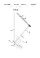
- FIG. 1is a schematic drawing showing the set-up of a crossed beam EMAT weld sensor in accordance with the present invention
- FIG. 2is a theoretical plot of a beam profile which agreed with observations made in the laboratory, showing the lobes of the beam;
- FIG. 3is a view similar to FIG. 1 showing a second embodiment of the invention which can be used as an alternative to crossed EMATS; and!
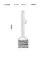
- FIG. 4is an enlarged view of the transducer which can be used either as a transmitting or receiving transducer, for the present invention
- FIG. 5is an enlarged view of the transducer as transmitting and receiving transducer for the alternate technique of the present invention showing dimensions in inches;
- FIG. 6shows the parameters that were used in plotting the theoretical curve for the diffraction pattern (or directivity pattern) of the transmitter EMAT curve.
- the principle of operating a crossed beam sensoris based on the fact that the root and crown act as a specular reflector (for reasonably smooth welds), and, therefore, the angle of incidence is equal to the angle of reflection.
- a small flawacts as a point source and the diffracted radiation is scattered over a wide angle.
- a large natural flawacts as a series of point sources with a large diffracted radiation pattern.
- the transmitteris positioned perpendicular to the flaw.
- the receiveris rotated relative to the transmitter at an angle which is past all of the major side lobes and at one of the zero points. This position is then the operating angle for the combination sensor.
- an EMAT transmitter 10excited by a pulsed RF signal, of conventional construction, is oriented to direct its transmission beam 12 perpendicular to the flat surface of a specular reflector 14 which may include a weld crown or root, in particular, a surface containing a weld to be inspected according to the present invention.
- a receiving EMAT 16is oriented at an angle which is selected according to the present invention and is advantageously 18° in FIG. 1, to the beam axis of the transmitter 10, for receiving reflected acoustic beams 18 and also reflected beams parallel to the transmission beam 12.
- the diffracted wavefronts 42 from the defect 8are detected by the receiver EMAT 16.
- FIG. 1shows the specular reflection pattern 6 and the zero point 4 from the specular refection 6 not detected by receiver EMAT 16. The beam from the zero point 4 of the specular reflection 6 is not received by the receiver EMAT.
- the angle between the transmitter and receiveris selected so that the receiver is past all major side lobes of the transmission beam and at one of the zero points.
- a computer program using Huygen's principlewas used to plot a theoretical directivity curve (also called a diffraction curve) of the transmitter EMAT at a metal path of three inches.
- the directivity curveexpresses the directional characteristics of the transmitted sound field (Krautkramer and Krautkramer, Ultrasonic Testing of Materials, Second Edition, Springer Verlag, New York, 1977.)
- the metal pathrefers to the distance along which the sound actually propagates in the metal.
- the theoretical curveis actually the diffraction pattern observed when plane waves propagate through a rectangular aperture of the same dimension as a transmitter EMAT.
- Huygen's principlewas used to plot the curve because Huygen's principle is valid for all points in front of the EMAT transmitter.
- this curveprovides the directional characteristics of the transmitter.
- the signal amplitude from the rectangular transmitter (or emitter) at a metal path of three incheswas normalized with respect to the peak amplitude and plotted on the vertical axis.
- the horizontal axisrepresented the angle with respect to a normal intersecting the center line of the transmitter.
- the results shown in FIG. 2agree with observations made in the laboratory (the positions of the predicted zeroes agreed with the experimentally observed position of the zeroes).
- the receiver EMATshould be rotated past all major side lobes to a zero point and left at that angle as long as the distance from the EMAT sensor to the weld center line is held constant.
- the sensorscould be SV EMATs (vertically polarized shear wave EMATS), SH EMATs (horizontally polarized EMATs), or surface wave EMATs.
- FIG. 3The alternate technique is illustrated in FIG. 3.
- Two collinear focused (or nonfocused) EMATs 22, 24are rotated at a suitable angle with respect to the specular reflector.
- FIG. 3shows the transmitted signal 30 and received signal 32 being sent and received by the EMATs 22, 24.
- FIG. 3also shows the specular reflection 34 not detected by the EMAT receiver.
- the anglecan be any convenient value (for example 45°) that provides good signal to noise ratio from the smallest expected flaw and eliminates the root and crown signal.
- the wavelength of soundwill be sufficiently close to the dimensions of the point diffractors on the flaw, and thus the flaw acts as a point source 40 or series of point sources and exhibits a wide angular diffraction pattern 42.
- the resultsare exactly analogous to those described for the crossed beam sensor. This technique has the advantage that the angle can be easily changed.
- the inventioneliminates the presence of the confusing crown and root signals. As a result, the data from the examination of the welds is much more easily examined.
- the simplicity in data interpretation resulting from the invention together with the elimination of couplant with EMATsgreatly improves the automation of weld inspections.
- the use of this techniqueallows the position of the sensor to be much closer to the weld than with other techniques because the flaw signals are not obscured by the crown and root signals.
- FIG. 4illustrates a typical EMAT, which can be used with the crossed sensor of the present invention, including dimensions.
- the EMAT of FIG. 4is advantageously an SV, 2 MHz transducer.
- the transmitter and receiver EMATsare mounted on 2 mil thick sheets of kapton, with the side of the kapton opposite the coils covered with 5 mil thick high molecular weight polyethylene. The side containing the coils was covered with a 1 mil thick sheet of polyethylene to serve as an electrical insulator. When the two coils are placed together in a "sandwich" configuration, one of the EMATs serves as transmitter and the other as a receiver.
- FIG. 5illustrates a typical collinear, focused sensor that can be used with the alternate technique.
- the pitch-catch EMAT in FIG. 5is a two MHz SV shear wave sensor.
- the transmitter and receiver coilsare mounted on 2 mil thick sheet of Kapton and covered with 5 mil thick high molecular weight polyethylene.
- the outer coilis typically the transmitter and the inner coil is typically the receiver.
- the source of the magnetic fieldis two neodymium-iron-boron magnets.
- the two magnetswere placed together with a thin copper sheet and thin sheet of cardboard taped to the bottom of the magnet to prevent sound propagating into the magnets themselves.
- the magnetswere placed on the combination EMAT, and the transmitter was rotated at the desired angle with respect to the receiver to achieve the embodiment of FIG. 1.
Landscapes
- Physics & Mathematics (AREA)
- Health & Medical Sciences (AREA)
- Life Sciences & Earth Sciences (AREA)
- Chemical & Material Sciences (AREA)
- Analytical Chemistry (AREA)
- Biochemistry (AREA)
- General Health & Medical Sciences (AREA)
- General Physics & Mathematics (AREA)
- Immunology (AREA)
- Pathology (AREA)
- Electromagnetism (AREA)
- Engineering & Computer Science (AREA)
- Mechanical Engineering (AREA)
- Acoustics & Sound (AREA)
- Investigating Or Analyzing Materials By The Use Of Ultrasonic Waves (AREA)
Abstract
Description
Claims (8)
Priority Applications (1)
| Application Number | Priority Date | Filing Date | Title |
|---|---|---|---|
| US08/531,573US5760307A (en) | 1994-03-18 | 1995-09-07 | EMAT probe and technique for weld inspection |
Applications Claiming Priority (2)
| Application Number | Priority Date | Filing Date | Title |
|---|---|---|---|
| US21084894A | 1994-03-18 | 1994-03-18 | |
| US08/531,573US5760307A (en) | 1994-03-18 | 1995-09-07 | EMAT probe and technique for weld inspection |
Related Parent Applications (1)
| Application Number | Title | Priority Date | Filing Date |
|---|---|---|---|
| US21084894AContinuation-In-Part | 1994-03-18 | 1994-03-18 |
Publications (1)
| Publication Number | Publication Date |
|---|---|
| US5760307Atrue US5760307A (en) | 1998-06-02 |
Family
ID=22784514
Family Applications (1)
| Application Number | Title | Priority Date | Filing Date |
|---|---|---|---|
| US08/531,573Expired - LifetimeUS5760307A (en) | 1994-03-18 | 1995-09-07 | EMAT probe and technique for weld inspection |
Country Status (2)
| Country | Link |
|---|---|
| US (1) | US5760307A (en) |
| CA (1) | CA2144597C (en) |
Cited By (49)
| Publication number | Priority date | Publication date | Assignee | Title |
|---|---|---|---|---|
| WO1999010737A1 (en)* | 1997-08-26 | 1999-03-04 | Mcdermott Technology, Inc. | Emat inspection of welds in thin steel plates of dissimilar thicknesses |
| US6038925A (en)* | 1997-03-21 | 2000-03-21 | Ebara Corporation | Focal type electromagnetic acoustic transducer and flaw detection system and method |
| US6192760B1 (en) | 1999-08-19 | 2001-02-27 | Mcdermott Technology, Inc. | EMAT transmit/receive switch |
| US6324912B1 (en) | 1998-02-24 | 2001-12-04 | Massachusetts Institute Of Technology | Flaw detection system using acoustic doppler effect |
| US20020108445A1 (en)* | 2000-11-21 | 2002-08-15 | Shi-Chang Wooh | Defect detection system and method |
| US6681632B2 (en)* | 2000-03-23 | 2004-01-27 | Snecma Moteurs | Method for evaluating the resilience of a welded assembly and corresponding analysis apparatus measuring the speeds of ultrasonic surface waves |
| US6728515B1 (en) | 2000-02-16 | 2004-04-27 | Massachusetts Institute Of Technology | Tuned wave phased array |
| US20040091076A1 (en)* | 2002-11-08 | 2004-05-13 | Pacific Gas & Electric Company | Method and system for nondestructive inspection of components |
| US20040134970A1 (en)* | 2002-07-17 | 2004-07-15 | Den Boer Johannis Josephus | EMAT weld inspection |
| US20040232207A1 (en)* | 2002-07-29 | 2004-11-25 | Alford Robert Andrew | Forge welding process |
| US20050050726A1 (en)* | 2002-07-17 | 2005-03-10 | Anderson Mark Wilson | Joining expandable tubulars |
| US6877555B2 (en) | 2001-04-24 | 2005-04-12 | Shell Oil Company | In situ thermal processing of an oil shale formation while inhibiting coking |
| US20050092715A1 (en)* | 2001-12-31 | 2005-05-05 | Alford Robert A. | Method for interconnecting tubulars by forge welding |
| US6932155B2 (en) | 2001-10-24 | 2005-08-23 | Shell Oil Company | In situ thermal processing of a hydrocarbon containing formation via backproducing through a heater well |
| US6948562B2 (en) | 2001-04-24 | 2005-09-27 | Shell Oil Company | Production of a blending agent using an in situ thermal process in a relatively permeable formation |
| US6969123B2 (en) | 2001-10-24 | 2005-11-29 | Shell Oil Company | Upgrading and mining of coal |
| US7011154B2 (en) | 2000-04-24 | 2006-03-14 | Shell Oil Company | In situ recovery from a kerogen and liquid hydrocarbon containing formation |
| US7040400B2 (en) | 2001-04-24 | 2006-05-09 | Shell Oil Company | In situ thermal processing of a relatively impermeable formation using an open wellbore |
| US7066254B2 (en) | 2001-04-24 | 2006-06-27 | Shell Oil Company | In situ thermal processing of a tar sands formation |
| US7073578B2 (en) | 2002-10-24 | 2006-07-11 | Shell Oil Company | Staged and/or patterned heating during in situ thermal processing of a hydrocarbon containing formation |
| US7077199B2 (en) | 2001-10-24 | 2006-07-18 | Shell Oil Company | In situ thermal processing of an oil reservoir formation |
| US7090013B2 (en) | 2001-10-24 | 2006-08-15 | Shell Oil Company | In situ thermal processing of a hydrocarbon containing formation to produce heated fluids |
| US7104319B2 (en) | 2001-10-24 | 2006-09-12 | Shell Oil Company | In situ thermal processing of a heavy oil diatomite formation |
| US7121342B2 (en) | 2003-04-24 | 2006-10-17 | Shell Oil Company | Thermal processes for subsurface formations |
| US7165615B2 (en) | 2001-10-24 | 2007-01-23 | Shell Oil Company | In situ recovery from a hydrocarbon containing formation using conductor-in-conduit heat sources with an electrically conductive material in the overburden |
| US20070158390A1 (en)* | 2003-07-17 | 2007-07-12 | Anderson Mark W | Forge welding tubulars |
| US7320364B2 (en) | 2004-04-23 | 2008-01-22 | Shell Oil Company | Inhibiting reflux in a heated well of an in situ conversion system |
| US7500528B2 (en) | 2005-04-22 | 2009-03-10 | Shell Oil Company | Low temperature barrier wellbores formed using water flushing |
| US7533719B2 (en) | 2006-04-21 | 2009-05-19 | Shell Oil Company | Wellhead with non-ferromagnetic materials |
| US7540324B2 (en) | 2006-10-20 | 2009-06-02 | Shell Oil Company | Heating hydrocarbon containing formations in a checkerboard pattern staged process |
| US7549470B2 (en) | 2005-10-24 | 2009-06-23 | Shell Oil Company | Solution mining and heating by oxidation for treating hydrocarbon containing formations |
| DE102008002394A1 (en)* | 2008-04-01 | 2009-10-22 | Ge Sensing & Inspection Technologies Gmbh | Universal test head for non-destructive ultrasound examination and associated method |
| US20090272526A1 (en)* | 2008-04-18 | 2009-11-05 | David Booth Burns | Electrical current flow between tunnels for use in heating subsurface hydrocarbon containing formations |
| US7798220B2 (en) | 2007-04-20 | 2010-09-21 | Shell Oil Company | In situ heat treatment of a tar sands formation after drive process treatment |
| US7798221B2 (en) | 2000-04-24 | 2010-09-21 | Shell Oil Company | In situ recovery from a hydrocarbon containing formation |
| US7866386B2 (en) | 2007-10-19 | 2011-01-11 | Shell Oil Company | In situ oxidation of subsurface formations |
| US20110296922A1 (en)* | 2010-06-07 | 2011-12-08 | Syed Mohamed Ali | Emat for inspecting thick-section welds and weld overlays during the welding process |
| US8220539B2 (en) | 2008-10-13 | 2012-07-17 | Shell Oil Company | Controlling hydrogen pressure in self-regulating nuclear reactors used to treat a subsurface formation |
| US8327932B2 (en) | 2009-04-10 | 2012-12-11 | Shell Oil Company | Recovering energy from a subsurface formation |
| US8631866B2 (en) | 2010-04-09 | 2014-01-21 | Shell Oil Company | Leak detection in circulated fluid systems for heating subsurface formations |
| US8701768B2 (en) | 2010-04-09 | 2014-04-22 | Shell Oil Company | Methods for treating hydrocarbon formations |
| US8820406B2 (en) | 2010-04-09 | 2014-09-02 | Shell Oil Company | Electrodes for electrical current flow heating of subsurface formations with conductive material in wellbore |
| US9016370B2 (en) | 2011-04-08 | 2015-04-28 | Shell Oil Company | Partial solution mining of hydrocarbon containing layers prior to in situ heat treatment |
| US9033042B2 (en) | 2010-04-09 | 2015-05-19 | Shell Oil Company | Forming bitumen barriers in subsurface hydrocarbon formations |
| US9309755B2 (en) | 2011-10-07 | 2016-04-12 | Shell Oil Company | Thermal expansion accommodation for circulated fluid systems used to heat subsurface formations |
| US9605524B2 (en) | 2012-01-23 | 2017-03-28 | Genie Ip B.V. | Heater pattern for in situ thermal processing of a subsurface hydrocarbon containing formation |
| US9689845B2 (en) | 2012-05-18 | 2017-06-27 | Areva Inc. | Angle beam ultrasonic probe for internal hex socket bolts |
| US10047594B2 (en) | 2012-01-23 | 2018-08-14 | Genie Ip B.V. | Heater pattern for in situ thermal processing of a subsurface hydrocarbon containing formation |
| US20220221429A1 (en)* | 2019-05-21 | 2022-07-14 | J. Van Beugen Beheer B.V. | Apparatus and method for pipeline inspection using emat generated shear waves |
Citations (11)
| Publication number | Priority date | Publication date | Assignee | Title |
|---|---|---|---|---|
| US3918295A (en)* | 1972-06-05 | 1975-11-11 | Raimar Pohlman | Method of nondestructively testing materials by ultrasound |
| US4289030A (en)* | 1979-08-01 | 1981-09-15 | Rockwell International Corporation | Nondestructive testing utilizing horizontally polarized shear waves |
| US4481824A (en)* | 1981-09-04 | 1984-11-13 | Hitachi, Ltd. | Weld detector |
| US4593568A (en)* | 1984-01-26 | 1986-06-10 | United Kingdom Atomic Energy Authority | Ultrasonic inspection of tube to tube plate welds |
| US5060518A (en)* | 1988-05-20 | 1991-10-29 | Moskovskoe Vysshee Tekhnicheskoe Uchilische Imeni N.E. Baumana | Method of ultrasonic inspection of welds of articles |
| US5085082A (en)* | 1990-10-24 | 1992-02-04 | The Babcock & Wilcox Company | Apparatus and method of discriminating flaw depths in the inspection of tubular products |
| US5154081A (en)* | 1989-07-21 | 1992-10-13 | Iowa State University Research Foundation, Inc. | Means and method for ultrasonic measurement of material properties |
| US5237874A (en)* | 1991-10-07 | 1993-08-24 | The Babcock & Wilcox Company | Rotating electromagnetic acoustic transducer for metal inspection |
| US5359898A (en)* | 1991-06-04 | 1994-11-01 | The Babcock & Wilcox Company | Hydrogen damage confirmation with EMATs |
| US5497662A (en)* | 1993-09-07 | 1996-03-12 | General Electric Company | Method and apparatus for measuring and controlling refracted angle of ultrasonic waves |
| US5537876A (en)* | 1994-08-02 | 1996-07-23 | Davidson; Paul K. | Apparatus and method for nondestructive evaluation of butt welds |
- 1995
- 1995-03-14CACA002144597Apatent/CA2144597C/ennot_activeExpired - Fee Related
- 1995-09-07USUS08/531,573patent/US5760307A/ennot_activeExpired - Lifetime
Patent Citations (11)
| Publication number | Priority date | Publication date | Assignee | Title |
|---|---|---|---|---|
| US3918295A (en)* | 1972-06-05 | 1975-11-11 | Raimar Pohlman | Method of nondestructively testing materials by ultrasound |
| US4289030A (en)* | 1979-08-01 | 1981-09-15 | Rockwell International Corporation | Nondestructive testing utilizing horizontally polarized shear waves |
| US4481824A (en)* | 1981-09-04 | 1984-11-13 | Hitachi, Ltd. | Weld detector |
| US4593568A (en)* | 1984-01-26 | 1986-06-10 | United Kingdom Atomic Energy Authority | Ultrasonic inspection of tube to tube plate welds |
| US5060518A (en)* | 1988-05-20 | 1991-10-29 | Moskovskoe Vysshee Tekhnicheskoe Uchilische Imeni N.E. Baumana | Method of ultrasonic inspection of welds of articles |
| US5154081A (en)* | 1989-07-21 | 1992-10-13 | Iowa State University Research Foundation, Inc. | Means and method for ultrasonic measurement of material properties |
| US5085082A (en)* | 1990-10-24 | 1992-02-04 | The Babcock & Wilcox Company | Apparatus and method of discriminating flaw depths in the inspection of tubular products |
| US5359898A (en)* | 1991-06-04 | 1994-11-01 | The Babcock & Wilcox Company | Hydrogen damage confirmation with EMATs |
| US5237874A (en)* | 1991-10-07 | 1993-08-24 | The Babcock & Wilcox Company | Rotating electromagnetic acoustic transducer for metal inspection |
| US5497662A (en)* | 1993-09-07 | 1996-03-12 | General Electric Company | Method and apparatus for measuring and controlling refracted angle of ultrasonic waves |
| US5537876A (en)* | 1994-08-02 | 1996-07-23 | Davidson; Paul K. | Apparatus and method for nondestructive evaluation of butt welds |
Cited By (227)
| Publication number | Priority date | Publication date | Assignee | Title |
|---|---|---|---|---|
| US6038925A (en)* | 1997-03-21 | 2000-03-21 | Ebara Corporation | Focal type electromagnetic acoustic transducer and flaw detection system and method |
| US6158285A (en)* | 1997-08-26 | 2000-12-12 | Mcdermott Technology, Inc. | EMAT inspection of welds in thin steel plates of dissimilar thicknesses |
| WO1999010737A1 (en)* | 1997-08-26 | 1999-03-04 | Mcdermott Technology, Inc. | Emat inspection of welds in thin steel plates of dissimilar thicknesses |
| US6324912B1 (en) | 1998-02-24 | 2001-12-04 | Massachusetts Institute Of Technology | Flaw detection system using acoustic doppler effect |
| US6854333B2 (en) | 1998-02-24 | 2005-02-15 | Massachusetts Institute Of Technology | Flaw detection system using acoustic doppler effect |
| US6715354B2 (en)* | 1998-02-24 | 2004-04-06 | Massachusetts Institute Of Technology | Flaw detection system using acoustic doppler effect |
| US6192760B1 (en) | 1999-08-19 | 2001-02-27 | Mcdermott Technology, Inc. | EMAT transmit/receive switch |
| US6728515B1 (en) | 2000-02-16 | 2004-04-27 | Massachusetts Institute Of Technology | Tuned wave phased array |
| US6681632B2 (en)* | 2000-03-23 | 2004-01-27 | Snecma Moteurs | Method for evaluating the resilience of a welded assembly and corresponding analysis apparatus measuring the speeds of ultrasonic surface waves |
| US7011154B2 (en) | 2000-04-24 | 2006-03-14 | Shell Oil Company | In situ recovery from a kerogen and liquid hydrocarbon containing formation |
| US7798221B2 (en) | 2000-04-24 | 2010-09-21 | Shell Oil Company | In situ recovery from a hydrocarbon containing formation |
| US8225866B2 (en) | 2000-04-24 | 2012-07-24 | Shell Oil Company | In situ recovery from a hydrocarbon containing formation |
| US8485252B2 (en) | 2000-04-24 | 2013-07-16 | Shell Oil Company | In situ recovery from a hydrocarbon containing formation |
| US8789586B2 (en) | 2000-04-24 | 2014-07-29 | Shell Oil Company | In situ recovery from a hydrocarbon containing formation |
| US20020108445A1 (en)* | 2000-11-21 | 2002-08-15 | Shi-Chang Wooh | Defect detection system and method |
| US6929067B2 (en) | 2001-04-24 | 2005-08-16 | Shell Oil Company | Heat sources with conductive material for in situ thermal processing of an oil shale formation |
| US7096942B1 (en) | 2001-04-24 | 2006-08-29 | Shell Oil Company | In situ thermal processing of a relatively permeable formation while controlling pressure |
| US8608249B2 (en) | 2001-04-24 | 2013-12-17 | Shell Oil Company | In situ thermal processing of an oil shale formation |
| US6915850B2 (en) | 2001-04-24 | 2005-07-12 | Shell Oil Company | In situ thermal processing of an oil shale formation having permeable and impermeable sections |
| US6918442B2 (en) | 2001-04-24 | 2005-07-19 | Shell Oil Company | In situ thermal processing of an oil shale formation in a reducing environment |
| US6918443B2 (en) | 2001-04-24 | 2005-07-19 | Shell Oil Company | In situ thermal processing of an oil shale formation to produce hydrocarbons having a selected carbon number range |
| US6923257B2 (en) | 2001-04-24 | 2005-08-02 | Shell Oil Company | In situ thermal processing of an oil shale formation to produce a condensate |
| US7055600B2 (en) | 2001-04-24 | 2006-06-06 | Shell Oil Company | In situ thermal recovery from a relatively permeable formation with controlled production rate |
| US6877555B2 (en) | 2001-04-24 | 2005-04-12 | Shell Oil Company | In situ thermal processing of an oil shale formation while inhibiting coking |
| US6948562B2 (en) | 2001-04-24 | 2005-09-27 | Shell Oil Company | Production of a blending agent using an in situ thermal process in a relatively permeable formation |
| US6951247B2 (en) | 2001-04-24 | 2005-10-04 | Shell Oil Company | In situ thermal processing of an oil shale formation using horizontal heat sources |
| US6964300B2 (en) | 2001-04-24 | 2005-11-15 | Shell Oil Company | In situ thermal recovery from a relatively permeable formation with backproduction through a heater wellbore |
| US6966374B2 (en) | 2001-04-24 | 2005-11-22 | Shell Oil Company | In situ thermal recovery from a relatively permeable formation using gas to increase mobility |
| US7225866B2 (en) | 2001-04-24 | 2007-06-05 | Shell Oil Company | In situ thermal processing of an oil shale formation using a pattern of heat sources |
| US6981548B2 (en) | 2001-04-24 | 2006-01-03 | Shell Oil Company | In situ thermal recovery from a relatively permeable formation |
| US6880633B2 (en) | 2001-04-24 | 2005-04-19 | Shell Oil Company | In situ thermal processing of an oil shale formation to produce a desired product |
| US6991033B2 (en) | 2001-04-24 | 2006-01-31 | Shell Oil Company | In situ thermal processing while controlling pressure in an oil shale formation |
| US6991032B2 (en) | 2001-04-24 | 2006-01-31 | Shell Oil Company | In situ thermal processing of an oil shale formation using a pattern of heat sources |
| US6991036B2 (en) | 2001-04-24 | 2006-01-31 | Shell Oil Company | Thermal processing of a relatively permeable formation |
| US6994169B2 (en) | 2001-04-24 | 2006-02-07 | Shell Oil Company | In situ thermal processing of an oil shale formation with a selected property |
| US6997518B2 (en) | 2001-04-24 | 2006-02-14 | Shell Oil Company | In situ thermal processing and solution mining of an oil shale formation |
| US7004251B2 (en) | 2001-04-24 | 2006-02-28 | Shell Oil Company | In situ thermal processing and remediation of an oil shale formation |
| US7004247B2 (en) | 2001-04-24 | 2006-02-28 | Shell Oil Company | Conductor-in-conduit heat sources for in situ thermal processing of an oil shale formation |
| US7735935B2 (en) | 2001-04-24 | 2010-06-15 | Shell Oil Company | In situ thermal processing of an oil shale formation containing carbonate minerals |
| US7013972B2 (en) | 2001-04-24 | 2006-03-21 | Shell Oil Company | In situ thermal processing of an oil shale formation using a natural distributed combustor |
| US7032660B2 (en) | 2001-04-24 | 2006-04-25 | Shell Oil Company | In situ thermal processing and inhibiting migration of fluids into or out of an in situ oil shale formation |
| US7040398B2 (en) | 2001-04-24 | 2006-05-09 | Shell Oil Company | In situ thermal processing of a relatively permeable formation in a reducing environment |
| US7040400B2 (en) | 2001-04-24 | 2006-05-09 | Shell Oil Company | In situ thermal processing of a relatively impermeable formation using an open wellbore |
| US7040399B2 (en) | 2001-04-24 | 2006-05-09 | Shell Oil Company | In situ thermal processing of an oil shale formation using a controlled heating rate |
| US7051807B2 (en) | 2001-04-24 | 2006-05-30 | Shell Oil Company | In situ thermal recovery from a relatively permeable formation with quality control |
| US7066254B2 (en) | 2001-04-24 | 2006-06-27 | Shell Oil Company | In situ thermal processing of a tar sands formation |
| US7051811B2 (en) | 2001-04-24 | 2006-05-30 | Shell Oil Company | In situ thermal processing through an open wellbore in an oil shale formation |
| US7063145B2 (en) | 2001-10-24 | 2006-06-20 | Shell Oil Company | Methods and systems for heating a hydrocarbon containing formation in situ with an opening contacting the earth's surface at two locations |
| US6991045B2 (en) | 2001-10-24 | 2006-01-31 | Shell Oil Company | Forming openings in a hydrocarbon containing formation using magnetic tracking |
| US7066257B2 (en) | 2001-10-24 | 2006-06-27 | Shell Oil Company | In situ recovery from lean and rich zones in a hydrocarbon containing formation |
| US7051808B1 (en) | 2001-10-24 | 2006-05-30 | Shell Oil Company | Seismic monitoring of in situ conversion in a hydrocarbon containing formation |
| US20100126727A1 (en)* | 2001-10-24 | 2010-05-27 | Shell Oil Company | In situ recovery from a hydrocarbon containing formation |
| US7077198B2 (en) | 2001-10-24 | 2006-07-18 | Shell Oil Company | In situ recovery from a hydrocarbon containing formation using barriers |
| US7077199B2 (en) | 2001-10-24 | 2006-07-18 | Shell Oil Company | In situ thermal processing of an oil reservoir formation |
| US7086465B2 (en) | 2001-10-24 | 2006-08-08 | Shell Oil Company | In situ production of a blending agent from a hydrocarbon containing formation |
| US7090013B2 (en) | 2001-10-24 | 2006-08-15 | Shell Oil Company | In situ thermal processing of a hydrocarbon containing formation to produce heated fluids |
| US6969123B2 (en) | 2001-10-24 | 2005-11-29 | Shell Oil Company | Upgrading and mining of coal |
| US7100994B2 (en) | 2001-10-24 | 2006-09-05 | Shell Oil Company | Producing hydrocarbons and non-hydrocarbon containing materials when treating a hydrocarbon containing formation |
| US7104319B2 (en) | 2001-10-24 | 2006-09-12 | Shell Oil Company | In situ thermal processing of a heavy oil diatomite formation |
| US6932155B2 (en) | 2001-10-24 | 2005-08-23 | Shell Oil Company | In situ thermal processing of a hydrocarbon containing formation via backproducing through a heater well |
| US8627887B2 (en) | 2001-10-24 | 2014-01-14 | Shell Oil Company | In situ recovery from a hydrocarbon containing formation |
| US7128153B2 (en) | 2001-10-24 | 2006-10-31 | Shell Oil Company | Treatment of a hydrocarbon containing formation after heating |
| US7156176B2 (en) | 2001-10-24 | 2007-01-02 | Shell Oil Company | Installation and use of removable heaters in a hydrocarbon containing formation |
| US7165615B2 (en) | 2001-10-24 | 2007-01-23 | Shell Oil Company | In situ recovery from a hydrocarbon containing formation using conductor-in-conduit heat sources with an electrically conductive material in the overburden |
| US7461691B2 (en) | 2001-10-24 | 2008-12-09 | Shell Oil Company | In situ recovery from a hydrocarbon containing formation |
| US7199325B2 (en) | 2001-12-31 | 2007-04-03 | Shell Oil Company | Method for interconnecting tubulars by forge welding |
| US20050092715A1 (en)* | 2001-12-31 | 2005-05-05 | Alford Robert A. | Method for interconnecting tubulars by forge welding |
| US20050050726A1 (en)* | 2002-07-17 | 2005-03-10 | Anderson Mark Wilson | Joining expandable tubulars |
| US7181821B2 (en) | 2002-07-17 | 2007-02-27 | Shell Oil Company | Joining expandable tubulars |
| US6896171B2 (en)* | 2002-07-17 | 2005-05-24 | Shell Oil Company | EMAT weld inspection |
| US20040134970A1 (en)* | 2002-07-17 | 2004-07-15 | Den Boer Johannis Josephus | EMAT weld inspection |
| US7282663B2 (en) | 2002-07-29 | 2007-10-16 | Shell Oil Company | Forge welding process |
| US20040232207A1 (en)* | 2002-07-29 | 2004-11-25 | Alford Robert Andrew | Forge welding process |
| US7121341B2 (en) | 2002-10-24 | 2006-10-17 | Shell Oil Company | Conductor-in-conduit temperature limited heaters |
| US7073578B2 (en) | 2002-10-24 | 2006-07-11 | Shell Oil Company | Staged and/or patterned heating during in situ thermal processing of a hydrocarbon containing formation |
| US8224164B2 (en) | 2002-10-24 | 2012-07-17 | Shell Oil Company | Insulated conductor temperature limited heaters |
| US8224163B2 (en) | 2002-10-24 | 2012-07-17 | Shell Oil Company | Variable frequency temperature limited heaters |
| US7219734B2 (en) | 2002-10-24 | 2007-05-22 | Shell Oil Company | Inhibiting wellbore deformation during in situ thermal processing of a hydrocarbon containing formation |
| US8238730B2 (en) | 2002-10-24 | 2012-08-07 | Shell Oil Company | High voltage temperature limited heaters |
| US20040091076A1 (en)* | 2002-11-08 | 2004-05-13 | Pacific Gas & Electric Company | Method and system for nondestructive inspection of components |
| US8579031B2 (en) | 2003-04-24 | 2013-11-12 | Shell Oil Company | Thermal processes for subsurface formations |
| US7640980B2 (en) | 2003-04-24 | 2010-01-05 | Shell Oil Company | Thermal processes for subsurface formations |
| US7360588B2 (en) | 2003-04-24 | 2008-04-22 | Shell Oil Company | Thermal processes for subsurface formations |
| US7942203B2 (en) | 2003-04-24 | 2011-05-17 | Shell Oil Company | Thermal processes for subsurface formations |
| US7121342B2 (en) | 2003-04-24 | 2006-10-17 | Shell Oil Company | Thermal processes for subsurface formations |
| US20070158390A1 (en)* | 2003-07-17 | 2007-07-12 | Anderson Mark W | Forge welding tubulars |
| US7774917B2 (en) | 2003-07-17 | 2010-08-17 | Tubefuse Applications B.V. | Forge welding tubulars |
| US7370704B2 (en) | 2004-04-23 | 2008-05-13 | Shell Oil Company | Triaxial temperature limited heater |
| US8355623B2 (en) | 2004-04-23 | 2013-01-15 | Shell Oil Company | Temperature limited heaters with high power factors |
| US7320364B2 (en) | 2004-04-23 | 2008-01-22 | Shell Oil Company | Inhibiting reflux in a heated well of an in situ conversion system |
| US7353872B2 (en) | 2004-04-23 | 2008-04-08 | Shell Oil Company | Start-up of temperature limited heaters using direct current (DC) |
| US7510000B2 (en) | 2004-04-23 | 2009-03-31 | Shell Oil Company | Reducing viscosity of oil for production from a hydrocarbon containing formation |
| US7357180B2 (en) | 2004-04-23 | 2008-04-15 | Shell Oil Company | Inhibiting effects of sloughing in wellbores |
| US7490665B2 (en) | 2004-04-23 | 2009-02-17 | Shell Oil Company | Variable frequency temperature limited heaters |
| US7481274B2 (en) | 2004-04-23 | 2009-01-27 | Shell Oil Company | Temperature limited heaters with relatively constant current |
| US7431076B2 (en) | 2004-04-23 | 2008-10-07 | Shell Oil Company | Temperature limited heaters using modulated DC power |
| US7424915B2 (en) | 2004-04-23 | 2008-09-16 | Shell Oil Company | Vacuum pumping of conductor-in-conduit heaters |
| US7383877B2 (en) | 2004-04-23 | 2008-06-10 | Shell Oil Company | Temperature limited heaters with thermally conductive fluid used to heat subsurface formations |
| US8230927B2 (en) | 2005-04-22 | 2012-07-31 | Shell Oil Company | Methods and systems for producing fluid from an in situ conversion process |
| US8233782B2 (en) | 2005-04-22 | 2012-07-31 | Shell Oil Company | Grouped exposed metal heaters |
| US7942197B2 (en) | 2005-04-22 | 2011-05-17 | Shell Oil Company | Methods and systems for producing fluid from an in situ conversion process |
| US7860377B2 (en) | 2005-04-22 | 2010-12-28 | Shell Oil Company | Subsurface connection methods for subsurface heaters |
| US7986869B2 (en) | 2005-04-22 | 2011-07-26 | Shell Oil Company | Varying properties along lengths of temperature limited heaters |
| US7500528B2 (en) | 2005-04-22 | 2009-03-10 | Shell Oil Company | Low temperature barrier wellbores formed using water flushing |
| US8027571B2 (en) | 2005-04-22 | 2011-09-27 | Shell Oil Company | In situ conversion process systems utilizing wellbores in at least two regions of a formation |
| US7527094B2 (en) | 2005-04-22 | 2009-05-05 | Shell Oil Company | Double barrier system for an in situ conversion process |
| US8070840B2 (en) | 2005-04-22 | 2011-12-06 | Shell Oil Company | Treatment of gas from an in situ conversion process |
| US7831134B2 (en) | 2005-04-22 | 2010-11-09 | Shell Oil Company | Grouped exposed metal heaters |
| US7575052B2 (en) | 2005-04-22 | 2009-08-18 | Shell Oil Company | In situ conversion process utilizing a closed loop heating system |
| US7575053B2 (en) | 2005-04-22 | 2009-08-18 | Shell Oil Company | Low temperature monitoring system for subsurface barriers |
| US8224165B2 (en) | 2005-04-22 | 2012-07-17 | Shell Oil Company | Temperature limited heater utilizing non-ferromagnetic conductor |
| US7546873B2 (en) | 2005-04-22 | 2009-06-16 | Shell Oil Company | Low temperature barriers for use with in situ processes |
| US7591310B2 (en) | 2005-10-24 | 2009-09-22 | Shell Oil Company | Methods of hydrotreating a liquid stream to remove clogging compounds |
| US7549470B2 (en) | 2005-10-24 | 2009-06-23 | Shell Oil Company | Solution mining and heating by oxidation for treating hydrocarbon containing formations |
| US7556095B2 (en) | 2005-10-24 | 2009-07-07 | Shell Oil Company | Solution mining dawsonite from hydrocarbon containing formations with a chelating agent |
| US7562706B2 (en) | 2005-10-24 | 2009-07-21 | Shell Oil Company | Systems and methods for producing hydrocarbons from tar sands formations |
| US7635025B2 (en) | 2005-10-24 | 2009-12-22 | Shell Oil Company | Cogeneration systems and processes for treating hydrocarbon containing formations |
| US7556096B2 (en) | 2005-10-24 | 2009-07-07 | Shell Oil Company | Varying heating in dawsonite zones in hydrocarbon containing formations |
| US7559367B2 (en) | 2005-10-24 | 2009-07-14 | Shell Oil Company | Temperature limited heater with a conduit substantially electrically isolated from the formation |
| US7584789B2 (en) | 2005-10-24 | 2009-09-08 | Shell Oil Company | Methods of cracking a crude product to produce additional crude products |
| US8606091B2 (en) | 2005-10-24 | 2013-12-10 | Shell Oil Company | Subsurface heaters with low sulfidation rates |
| US7559368B2 (en) | 2005-10-24 | 2009-07-14 | Shell Oil Company | Solution mining systems and methods for treating hydrocarbon containing formations |
| US8151880B2 (en) | 2005-10-24 | 2012-04-10 | Shell Oil Company | Methods of making transportation fuel |
| US7581589B2 (en) | 2005-10-24 | 2009-09-01 | Shell Oil Company | Methods of producing alkylated hydrocarbons from an in situ heat treatment process liquid |
| US7785427B2 (en) | 2006-04-21 | 2010-08-31 | Shell Oil Company | High strength alloys |
| US8083813B2 (en) | 2006-04-21 | 2011-12-27 | Shell Oil Company | Methods of producing transportation fuel |
| US7793722B2 (en) | 2006-04-21 | 2010-09-14 | Shell Oil Company | Non-ferromagnetic overburden casing |
| US8192682B2 (en) | 2006-04-21 | 2012-06-05 | Shell Oil Company | High strength alloys |
| US7635023B2 (en) | 2006-04-21 | 2009-12-22 | Shell Oil Company | Time sequenced heating of multiple layers in a hydrocarbon containing formation |
| US7533719B2 (en) | 2006-04-21 | 2009-05-19 | Shell Oil Company | Wellhead with non-ferromagnetic materials |
| US7597147B2 (en) | 2006-04-21 | 2009-10-06 | Shell Oil Company | Temperature limited heaters using phase transformation of ferromagnetic material |
| US7866385B2 (en) | 2006-04-21 | 2011-01-11 | Shell Oil Company | Power systems utilizing the heat of produced formation fluid |
| US7683296B2 (en) | 2006-04-21 | 2010-03-23 | Shell Oil Company | Adjusting alloy compositions for selected properties in temperature limited heaters |
| US7631689B2 (en) | 2006-04-21 | 2009-12-15 | Shell Oil Company | Sulfur barrier for use with in situ processes for treating formations |
| US7610962B2 (en) | 2006-04-21 | 2009-11-03 | Shell Oil Company | Sour gas injection for use with in situ heat treatment |
| US7673786B2 (en) | 2006-04-21 | 2010-03-09 | Shell Oil Company | Welding shield for coupling heaters |
| US8857506B2 (en) | 2006-04-21 | 2014-10-14 | Shell Oil Company | Alternate energy source usage methods for in situ heat treatment processes |
| US7604052B2 (en) | 2006-04-21 | 2009-10-20 | Shell Oil Company | Compositions produced using an in situ heat treatment process |
| US7912358B2 (en) | 2006-04-21 | 2011-03-22 | Shell Oil Company | Alternate energy source usage for in situ heat treatment processes |
| US7562707B2 (en) | 2006-10-20 | 2009-07-21 | Shell Oil Company | Heating hydrocarbon containing formations in a line drive staged process |
| US8191630B2 (en) | 2006-10-20 | 2012-06-05 | Shell Oil Company | Creating fluid injectivity in tar sands formations |
| US7631690B2 (en) | 2006-10-20 | 2009-12-15 | Shell Oil Company | Heating hydrocarbon containing formations in a spiral startup staged sequence |
| US7635024B2 (en) | 2006-10-20 | 2009-12-22 | Shell Oil Company | Heating tar sands formations to visbreaking temperatures |
| US7644765B2 (en) | 2006-10-20 | 2010-01-12 | Shell Oil Company | Heating tar sands formations while controlling pressure |
| US7540324B2 (en) | 2006-10-20 | 2009-06-02 | Shell Oil Company | Heating hydrocarbon containing formations in a checkerboard pattern staged process |
| US7845411B2 (en) | 2006-10-20 | 2010-12-07 | Shell Oil Company | In situ heat treatment process utilizing a closed loop heating system |
| US8555971B2 (en) | 2006-10-20 | 2013-10-15 | Shell Oil Company | Treating tar sands formations with dolomite |
| US7673681B2 (en) | 2006-10-20 | 2010-03-09 | Shell Oil Company | Treating tar sands formations with karsted zones |
| US7677310B2 (en) | 2006-10-20 | 2010-03-16 | Shell Oil Company | Creating and maintaining a gas cap in tar sands formations |
| US7841401B2 (en) | 2006-10-20 | 2010-11-30 | Shell Oil Company | Gas injection to inhibit migration during an in situ heat treatment process |
| US7677314B2 (en) | 2006-10-20 | 2010-03-16 | Shell Oil Company | Method of condensing vaporized water in situ to treat tar sands formations |
| US7681647B2 (en) | 2006-10-20 | 2010-03-23 | Shell Oil Company | Method of producing drive fluid in situ in tar sands formations |
| US7703513B2 (en) | 2006-10-20 | 2010-04-27 | Shell Oil Company | Wax barrier for use with in situ processes for treating formations |
| US7717171B2 (en) | 2006-10-20 | 2010-05-18 | Shell Oil Company | Moving hydrocarbons through portions of tar sands formations with a fluid |
| US7730947B2 (en) | 2006-10-20 | 2010-06-08 | Shell Oil Company | Creating fluid injectivity in tar sands formations |
| US7730946B2 (en) | 2006-10-20 | 2010-06-08 | Shell Oil Company | Treating tar sands formations with dolomite |
| US7730945B2 (en) | 2006-10-20 | 2010-06-08 | Shell Oil Company | Using geothermal energy to heat a portion of a formation for an in situ heat treatment process |
| US8327681B2 (en) | 2007-04-20 | 2012-12-11 | Shell Oil Company | Wellbore manufacturing processes for in situ heat treatment processes |
| US9181780B2 (en) | 2007-04-20 | 2015-11-10 | Shell Oil Company | Controlling and assessing pressure conditions during treatment of tar sands formations |
| US7950453B2 (en) | 2007-04-20 | 2011-05-31 | Shell Oil Company | Downhole burner systems and methods for heating subsurface formations |
| US7841425B2 (en) | 2007-04-20 | 2010-11-30 | Shell Oil Company | Drilling subsurface wellbores with cutting structures |
| US8459359B2 (en) | 2007-04-20 | 2013-06-11 | Shell Oil Company | Treating nahcolite containing formations and saline zones |
| US7798220B2 (en) | 2007-04-20 | 2010-09-21 | Shell Oil Company | In situ heat treatment of a tar sands formation after drive process treatment |
| US7931086B2 (en) | 2007-04-20 | 2011-04-26 | Shell Oil Company | Heating systems for heating subsurface formations |
| US8381815B2 (en) | 2007-04-20 | 2013-02-26 | Shell Oil Company | Production from multiple zones of a tar sands formation |
| US7832484B2 (en) | 2007-04-20 | 2010-11-16 | Shell Oil Company | Molten salt as a heat transfer fluid for heating a subsurface formation |
| US7849922B2 (en) | 2007-04-20 | 2010-12-14 | Shell Oil Company | In situ recovery from residually heated sections in a hydrocarbon containing formation |
| US8042610B2 (en) | 2007-04-20 | 2011-10-25 | Shell Oil Company | Parallel heater system for subsurface formations |
| US8662175B2 (en) | 2007-04-20 | 2014-03-04 | Shell Oil Company | Varying properties of in situ heat treatment of a tar sands formation based on assessed viscosities |
| US8791396B2 (en) | 2007-04-20 | 2014-07-29 | Shell Oil Company | Floating insulated conductors for heating subsurface formations |
| US7841408B2 (en) | 2007-04-20 | 2010-11-30 | Shell Oil Company | In situ heat treatment from multiple layers of a tar sands formation |
| US8146669B2 (en) | 2007-10-19 | 2012-04-03 | Shell Oil Company | Multi-step heater deployment in a subsurface formation |
| US8196658B2 (en) | 2007-10-19 | 2012-06-12 | Shell Oil Company | Irregular spacing of heat sources for treating hydrocarbon containing formations |
| US8011451B2 (en) | 2007-10-19 | 2011-09-06 | Shell Oil Company | Ranging methods for developing wellbores in subsurface formations |
| US8162059B2 (en) | 2007-10-19 | 2012-04-24 | Shell Oil Company | Induction heaters used to heat subsurface formations |
| US8113272B2 (en) | 2007-10-19 | 2012-02-14 | Shell Oil Company | Three-phase heaters with common overburden sections for heating subsurface formations |
| US8272455B2 (en) | 2007-10-19 | 2012-09-25 | Shell Oil Company | Methods for forming wellbores in heated formations |
| US8276661B2 (en) | 2007-10-19 | 2012-10-02 | Shell Oil Company | Heating subsurface formations by oxidizing fuel on a fuel carrier |
| US8536497B2 (en) | 2007-10-19 | 2013-09-17 | Shell Oil Company | Methods for forming long subsurface heaters |
| US8146661B2 (en) | 2007-10-19 | 2012-04-03 | Shell Oil Company | Cryogenic treatment of gas |
| US7866388B2 (en) | 2007-10-19 | 2011-01-11 | Shell Oil Company | High temperature methods for forming oxidizer fuel |
| US8240774B2 (en) | 2007-10-19 | 2012-08-14 | Shell Oil Company | Solution mining and in situ treatment of nahcolite beds |
| US7866386B2 (en) | 2007-10-19 | 2011-01-11 | Shell Oil Company | In situ oxidation of subsurface formations |
| DE102008002394A1 (en)* | 2008-04-01 | 2009-10-22 | Ge Sensing & Inspection Technologies Gmbh | Universal test head for non-destructive ultrasound examination and associated method |
| US9528322B2 (en) | 2008-04-18 | 2016-12-27 | Shell Oil Company | Dual motor systems and non-rotating sensors for use in developing wellbores in subsurface formations |
| US8151907B2 (en) | 2008-04-18 | 2012-04-10 | Shell Oil Company | Dual motor systems and non-rotating sensors for use in developing wellbores in subsurface formations |
| US8636323B2 (en) | 2008-04-18 | 2014-01-28 | Shell Oil Company | Mines and tunnels for use in treating subsurface hydrocarbon containing formations |
| US8162405B2 (en) | 2008-04-18 | 2012-04-24 | Shell Oil Company | Using tunnels for treating subsurface hydrocarbon containing formations |
| US8177305B2 (en) | 2008-04-18 | 2012-05-15 | Shell Oil Company | Heater connections in mines and tunnels for use in treating subsurface hydrocarbon containing formations |
| US8752904B2 (en) | 2008-04-18 | 2014-06-17 | Shell Oil Company | Heated fluid flow in mines and tunnels used in heating subsurface hydrocarbon containing formations |
| US20090272526A1 (en)* | 2008-04-18 | 2009-11-05 | David Booth Burns | Electrical current flow between tunnels for use in heating subsurface hydrocarbon containing formations |
| US8562078B2 (en) | 2008-04-18 | 2013-10-22 | Shell Oil Company | Hydrocarbon production from mines and tunnels used in treating subsurface hydrocarbon containing formations |
| US8172335B2 (en) | 2008-04-18 | 2012-05-08 | Shell Oil Company | Electrical current flow between tunnels for use in heating subsurface hydrocarbon containing formations |
| US8267185B2 (en) | 2008-10-13 | 2012-09-18 | Shell Oil Company | Circulated heated transfer fluid systems used to treat a subsurface formation |
| US9051829B2 (en) | 2008-10-13 | 2015-06-09 | Shell Oil Company | Perforated electrical conductors for treating subsurface formations |
| US8881806B2 (en) | 2008-10-13 | 2014-11-11 | Shell Oil Company | Systems and methods for treating a subsurface formation with electrical conductors |
| US8220539B2 (en) | 2008-10-13 | 2012-07-17 | Shell Oil Company | Controlling hydrogen pressure in self-regulating nuclear reactors used to treat a subsurface formation |
| US8353347B2 (en) | 2008-10-13 | 2013-01-15 | Shell Oil Company | Deployment of insulated conductors for treating subsurface formations |
| US8261832B2 (en) | 2008-10-13 | 2012-09-11 | Shell Oil Company | Heating subsurface formations with fluids |
| US9129728B2 (en) | 2008-10-13 | 2015-09-08 | Shell Oil Company | Systems and methods of forming subsurface wellbores |
| US8256512B2 (en) | 2008-10-13 | 2012-09-04 | Shell Oil Company | Movable heaters for treating subsurface hydrocarbon containing formations |
| US9022118B2 (en) | 2008-10-13 | 2015-05-05 | Shell Oil Company | Double insulated heaters for treating subsurface formations |
| US8281861B2 (en) | 2008-10-13 | 2012-10-09 | Shell Oil Company | Circulated heated transfer fluid heating of subsurface hydrocarbon formations |
| US8267170B2 (en) | 2008-10-13 | 2012-09-18 | Shell Oil Company | Offset barrier wells in subsurface formations |
| US8327932B2 (en) | 2009-04-10 | 2012-12-11 | Shell Oil Company | Recovering energy from a subsurface formation |
| US8448707B2 (en) | 2009-04-10 | 2013-05-28 | Shell Oil Company | Non-conducting heater casings |
| US8434555B2 (en) | 2009-04-10 | 2013-05-07 | Shell Oil Company | Irregular pattern treatment of a subsurface formation |
| US8851170B2 (en) | 2009-04-10 | 2014-10-07 | Shell Oil Company | Heater assisted fluid treatment of a subsurface formation |
| US8833453B2 (en) | 2010-04-09 | 2014-09-16 | Shell Oil Company | Electrodes for electrical current flow heating of subsurface formations with tapered copper thickness |
| US9399905B2 (en) | 2010-04-09 | 2016-07-26 | Shell Oil Company | Leak detection in circulated fluid systems for heating subsurface formations |
| US8820406B2 (en) | 2010-04-09 | 2014-09-02 | Shell Oil Company | Electrodes for electrical current flow heating of subsurface formations with conductive material in wellbore |
| US8739874B2 (en) | 2010-04-09 | 2014-06-03 | Shell Oil Company | Methods for heating with slots in hydrocarbon formations |
| US9022109B2 (en) | 2010-04-09 | 2015-05-05 | Shell Oil Company | Leak detection in circulated fluid systems for heating subsurface formations |
| US9033042B2 (en) | 2010-04-09 | 2015-05-19 | Shell Oil Company | Forming bitumen barriers in subsurface hydrocarbon formations |
| US8701769B2 (en) | 2010-04-09 | 2014-04-22 | Shell Oil Company | Methods for treating hydrocarbon formations based on geology |
| US9127538B2 (en) | 2010-04-09 | 2015-09-08 | Shell Oil Company | Methodologies for treatment of hydrocarbon formations using staged pyrolyzation |
| US9127523B2 (en) | 2010-04-09 | 2015-09-08 | Shell Oil Company | Barrier methods for use in subsurface hydrocarbon formations |
| US8701768B2 (en) | 2010-04-09 | 2014-04-22 | Shell Oil Company | Methods for treating hydrocarbon formations |
| US8631866B2 (en) | 2010-04-09 | 2014-01-21 | Shell Oil Company | Leak detection in circulated fluid systems for heating subsurface formations |
| US20110296922A1 (en)* | 2010-06-07 | 2011-12-08 | Syed Mohamed Ali | Emat for inspecting thick-section welds and weld overlays during the welding process |
| US9016370B2 (en) | 2011-04-08 | 2015-04-28 | Shell Oil Company | Partial solution mining of hydrocarbon containing layers prior to in situ heat treatment |
| US9309755B2 (en) | 2011-10-07 | 2016-04-12 | Shell Oil Company | Thermal expansion accommodation for circulated fluid systems used to heat subsurface formations |
| US9605524B2 (en) | 2012-01-23 | 2017-03-28 | Genie Ip B.V. | Heater pattern for in situ thermal processing of a subsurface hydrocarbon containing formation |
| US10047594B2 (en) | 2012-01-23 | 2018-08-14 | Genie Ip B.V. | Heater pattern for in situ thermal processing of a subsurface hydrocarbon containing formation |
| US9689845B2 (en) | 2012-05-18 | 2017-06-27 | Areva Inc. | Angle beam ultrasonic probe for internal hex socket bolts |
| US20220221429A1 (en)* | 2019-05-21 | 2022-07-14 | J. Van Beugen Beheer B.V. | Apparatus and method for pipeline inspection using emat generated shear waves |
| US12247949B2 (en)* | 2019-05-21 | 2025-03-11 | P & L Pipe Survey B.V. | Apparatus and method for pipeline inspection using EMAT generated shear waves |
Also Published As
| Publication number | Publication date |
|---|---|
| CA2144597C (en) | 1999-08-10 |
| CA2144597A1 (en) | 1995-09-19 |
Similar Documents
| Publication | Publication Date | Title |
|---|---|---|
| US5760307A (en) | EMAT probe and technique for weld inspection | |
| Kelly et al. | Applications of through-air ultrasound for rapid NDE scanning in the aerospace industry | |
| Dixon et al. | A laser–EMAT system for ultrasonic weld inspection | |
| Salzburger et al. | EMAT pipe inspection with guided waves | |
| US20110296922A1 (en) | Emat for inspecting thick-section welds and weld overlays during the welding process | |
| CN111602049B (en) | Arrangement for non-destructive testing and testing method thereof | |
| US5383365A (en) | Crack orientation determination and detection using horizontally polarized shear waves | |
| US4509369A (en) | Near surface inspection system | |
| CN2615666Y (en) | Phased array probe for solid material ultrasound nondestructive testing | |
| Peters et al. | Non‐contact inspection of composites using air‐coupled ultrasound | |
| JP4196643B2 (en) | Method and apparatus for imaging internal defect by ultrasonic wave | |
| Bernstein et al. | Hybrid laser/broadband EMAT ultrasonic system for characterizing cracks in metals | |
| Xiang et al. | Multiple wavemode scanning for near and far-side defect characterisation | |
| Bendec et al. | Ultrasonic Lamb wave method for sizing of spot welds | |
| JPH05180807A (en) | Method for selecting ultrasonic-wave probe and probe selected by method thereof | |
| Lam et al. | Flaw characterization based on diffraction of ultrasonic waves | |
| US6158285A (en) | EMAT inspection of welds in thin steel plates of dissimilar thicknesses | |
| Gao et al. | Inspection of austenitic weld with EMATs | |
| Bond | Ultrasonic transduction (transducer elements) | |
| Peyton et al. | Optimised Shear Horizontal Guided Wave Inspection Set-Up for Titanium Welds. | |
| Bond | Basic inspection methods (Pulse-echo and transmission methods) | |
| Bagyinszki et al. | Applicability of Procedural Variants in Ultrasonic Testing | |
| Chiou et al. | Quasi pulse-echo ultrasonic technique for flaw classification | |
| Thompson et al. | Quantitative ultrasonics | |
| Du | Non-Destructive Inspection of Surface Defects in Cylindrical Structures |
Legal Events
| Date | Code | Title | Description |
|---|---|---|---|
| AS | Assignment | Owner name:BABCOCK & WILCOX COMPANY, THE, LOUISIANA Free format text:ASSIGNMENT OF ASSIGNORS INTEREST;ASSIGNORS:LATIMER, PAUL J.;MACLAUCHLAN, DANIEL T.;REEL/FRAME:008062/0186 Effective date:19950905 | |
| AS | Assignment | Owner name:MCDERMOTT TECHNOLOGY, INC., LOUISIANA Free format text:ASSIGNMENT OF ASSIGNORS INTEREST;ASSIGNOR:BABCOCK & WILCOX COMPANY, THE;REEL/FRAME:008820/0595 Effective date:19970630 | |
| STCF | Information on status: patent grant | Free format text:PATENTED CASE | |
| AS | Assignment | Owner name:MCDERMOTT TECHNOLOGY, INC., LOUISIANA Free format text:CORRECT ASSIGNMENT AS ORIGINALLY RECORDED ON REEL 8820 FRAME 0595 TO DELETE ITEMS ON ATTACHED PAGE 2.;ASSIGNOR:BABCOCK & WILCOX COMPANY, THE;REEL/FRAME:009405/0374 Effective date:19970630 | |
| FEPP | Fee payment procedure | Free format text:PAYOR NUMBER ASSIGNED (ORIGINAL EVENT CODE: ASPN); ENTITY STATUS OF PATENT OWNER: LARGE ENTITY | |
| FPAY | Fee payment | Year of fee payment:4 | |
| FPAY | Fee payment | Year of fee payment:8 | |
| FPAY | Fee payment | Year of fee payment:12 | |
| AS | Assignment | Owner name:BABCOCK & WILCOX TECHNOLOGY, INC., VIRGINIA Free format text:CHANGE OF NAME;ASSIGNOR:MCDERMOTT TECHNOLOGY, INC;REEL/FRAME:035664/0495 Effective date:20100420 | |
| AS | Assignment | Owner name:BANK OF AMERICA, N.A., AS ADMINISTRATIVE AGENT, CA Free format text:SECURITY INTEREST;ASSIGNOR:BWXT INVESTMENT COMPANY;REEL/FRAME:036109/0665 Effective date:20150630 | |
| AS | Assignment | Owner name:BABCOCK & WILCOX INVESTMENT COMPANY, UNITED STATES Free format text:ASSIGNMENT OF ASSIGNORS INTEREST;ASSIGNOR:BABCOCK & WILCOX TECHNOLOGY, LLC;REEL/FRAME:036351/0069 Effective date:20150627 Owner name:BWXT INVESTMENT COMPANY, NORTH CAROLINA Free format text:CHANGE OF NAME;ASSIGNOR:BABCOCK & WILCOX INVESTMENT COMPANY;REEL/FRAME:036388/0412 Effective date:20150629 | |
| AS | Assignment | Owner name:BWXT INVESTMENT COMPANY, VIRGINIA Free format text:RELEASE BY SECURED PARTY;ASSIGNOR:BANK OF AMERICA, N.A.;REEL/FRAME:045906/0911 Effective date:20180524 |