US5759329A - Fluoropolymer composite tube and method of preparation - Google Patents
Fluoropolymer composite tube and method of preparationDownload PDFInfo
- Publication number
- US5759329A US5759329AUS08/265,679US26567994AUS5759329AUS 5759329 AUS5759329 AUS 5759329AUS 26567994 AUS26567994 AUS 26567994AUS 5759329 AUS5759329 AUS 5759329A
- Authority
- US
- United States
- Prior art keywords
- fluoropolymer
- layer
- substrate
- extrusion
- thermosetting
- Prior art date
- Legal status (The legal status is an assumption and is not a legal conclusion. Google has not performed a legal analysis and makes no representation as to the accuracy of the status listed.)
- Expired - Lifetime
Links
- 229920002313fluoropolymerPolymers0.000titleclaimsabstractdescription87
- 239000004811fluoropolymerSubstances0.000titleclaimsabstractdescription84
- 238000000034methodMethods0.000titleclaimsabstractdescription29
- 239000002131composite materialSubstances0.000titleabstractdescription13
- 239000000758substrateSubstances0.000claimsabstractdescription46
- 229920001187thermosetting polymerPolymers0.000claimsabstractdescription40
- 229920001971elastomerPolymers0.000claimsabstractdescription27
- 239000000806elastomerSubstances0.000claimsabstractdescription24
- 239000000126substanceSubstances0.000claimsabstractdescription22
- 229920002725thermoplastic elastomerPolymers0.000claimsabstractdescription20
- 229920000642polymerPolymers0.000claimsabstractdescription14
- 239000012298atmosphereSubstances0.000claimsabstractdescription12
- 239000003795chemical substances by applicationSubstances0.000claimsabstractdescription12
- 239000010410layerSubstances0.000claimsdescription76
- 238000001125extrusionMethods0.000claimsdescription65
- 239000005977EthyleneSubstances0.000claimsdescription8
- 229920000058polyacrylatePolymers0.000claimsdescription7
- JOYRKODLDBILNP-UHFFFAOYSA-NEthyl urethaneChemical compoundCCOC(N)=OJOYRKODLDBILNP-UHFFFAOYSA-N0.000claimsdescription6
- VGGSQFUCUMXWEO-UHFFFAOYSA-NEtheneChemical compoundC=CVGGSQFUCUMXWEO-UHFFFAOYSA-N0.000claimsdescription5
- 229920000800acrylic rubberPolymers0.000claimsdescription4
- 229920001169thermoplasticPolymers0.000claimsdescription4
- 239000004709Chlorinated polyethyleneSubstances0.000claimsdescription3
- BRLQWZUYTZBJKN-UHFFFAOYSA-NEpichlorohydrinChemical compoundClCC1CO1BRLQWZUYTZBJKN-UHFFFAOYSA-N0.000claimsdescription3
- 229920006169PerfluoroelastomerPolymers0.000claimsdescription3
- 239000004721Polyphenylene oxideSubstances0.000claimsdescription3
- 239000002174Styrene-butadieneSubstances0.000claimsdescription3
- 229920006311Urethane elastomerPolymers0.000claimsdescription3
- 150000001408amidesChemical class0.000claimsdescription3
- MTAZNLWOLGHBHU-UHFFFAOYSA-Nbutadiene-styrene rubberChemical compoundC=CC=C.C=CC1=CC=CC=C1MTAZNLWOLGHBHU-UHFFFAOYSA-N0.000claimsdescription3
- 150000002148estersChemical class0.000claimsdescription3
- 229920001973fluoroelastomerPolymers0.000claimsdescription3
- 229920002681hypalonPolymers0.000claimsdescription3
- 150000002825nitrilesChemical class0.000claimsdescription3
- 229920000728polyesterPolymers0.000claimsdescription3
- 229920000570polyetherPolymers0.000claimsdescription3
- 229920001296polysiloxanePolymers0.000claimsdescription3
- 239000005077polysulfideSubstances0.000claimsdescription3
- 229920001021polysulfidePolymers0.000claimsdescription3
- 150000008117polysulfidesPolymers0.000claimsdescription3
- 229920002635polyurethanePolymers0.000claimsdescription3
- 239000004814polyurethaneSubstances0.000claimsdescription3
- 239000011115styrene butadieneSubstances0.000claimsdescription3
- 229920003048styrene butadiene rubberPolymers0.000claimsdescription3
- 230000003213activating effectEffects0.000claimsdescription2
- 238000009832plasma treatmentMethods0.000claims5
- 239000012080ambient airSubstances0.000claims4
- 239000012790adhesive layerSubstances0.000claims3
- 239000004634thermosetting polymerSubstances0.000claims2
- 239000004416thermosoftening plasticSubstances0.000claims2
- YCKRFDGAMUMZLT-UHFFFAOYSA-NFluorine atomChemical compound[F]YCKRFDGAMUMZLT-UHFFFAOYSA-N0.000claims1
- 229910052731fluorineInorganic materials0.000claims1
- 239000011737fluorineSubstances0.000claims1
- 238000003825pressingMethods0.000claims1
- 239000000446fuelSubstances0.000abstractdescription25
- 239000004215Carbon black (E152)Substances0.000abstractdescription8
- 229930195733hydrocarbonNatural products0.000abstractdescription8
- 150000002430hydrocarbonsChemical class0.000abstractdescription8
- NBVXSUQYWXRMNV-UHFFFAOYSA-NfluoromethaneChemical compoundFCNBVXSUQYWXRMNV-UHFFFAOYSA-N0.000abstractdescription6
- 238000009826distributionMethods0.000description67
- 239000000463materialSubstances0.000description51
- 239000007789gasSubstances0.000description27
- 208000028659dischargeDiseases0.000description25
- 239000012530fluidSubstances0.000description21
- 238000004891communicationMethods0.000description18
- 230000004913activationEffects0.000description8
- 229920000840ethylene tetrafluoroethylene copolymerPolymers0.000description6
- 239000000853adhesiveSubstances0.000description5
- 230000001070adhesive effectEffects0.000description5
- -1polytetrafluoroethylenePolymers0.000description5
- 229920001343polytetrafluoroethylenePolymers0.000description5
- 239000004810polytetrafluoroethyleneSubstances0.000description5
- 239000002033PVDF binderSubstances0.000description4
- 229920006355TefzelPolymers0.000description4
- QHSJIZLJUFMIFP-UHFFFAOYSA-Nethene;1,1,2,2-tetrafluoroetheneChemical compoundC=C.FC(F)=C(F)FQHSJIZLJUFMIFP-UHFFFAOYSA-N0.000description4
- 230000003993interactionEffects0.000description4
- 238000004519manufacturing processMethods0.000description4
- 239000002245particleSubstances0.000description4
- 229920002981polyvinylidene fluoridePolymers0.000description4
- 230000008569processEffects0.000description4
- QGZKDVFQNNGYKY-UHFFFAOYSA-NAmmoniaChemical compoundNQGZKDVFQNNGYKY-UHFFFAOYSA-N0.000description3
- UHOVQNZJYSORNB-UHFFFAOYSA-NBenzeneChemical compoundC1=CC=CC=C1UHOVQNZJYSORNB-UHFFFAOYSA-N0.000description3
- ZHNUHDYFZUAESO-UHFFFAOYSA-NFormamideChemical compoundNC=OZHNUHDYFZUAESO-UHFFFAOYSA-N0.000description3
- 229920006368HylarPolymers0.000description3
- YXFVVABEGXRONW-UHFFFAOYSA-NTolueneChemical compoundCC1=CC=CC=C1YXFVVABEGXRONW-UHFFFAOYSA-N0.000description3
- 150000001412aminesChemical class0.000description3
- 230000000694effectsEffects0.000description3
- 239000001257hydrogenSubstances0.000description3
- 229910052739hydrogenInorganic materials0.000description3
- 238000012545processingMethods0.000description3
- 239000005060rubberSubstances0.000description3
- ADTHJEKIUIOLBX-UHFFFAOYSA-N1,1,3,4,4,5,5,6,6,6-decafluoro-3-(trifluoromethyl)hex-1-eneChemical compoundFC(C(F)(F)F)(C(C(C(F)(F)F)(C=C(F)F)F)(F)F)FADTHJEKIUIOLBX-UHFFFAOYSA-N0.000description2
- IJGRMHOSHXDMSA-UHFFFAOYSA-NAtomic nitrogenChemical compoundN#NIJGRMHOSHXDMSA-UHFFFAOYSA-N0.000description2
- CURLTUGMZLYLDI-UHFFFAOYSA-NCarbon dioxideChemical compoundO=C=OCURLTUGMZLYLDI-UHFFFAOYSA-N0.000description2
- 229920001780ECTFEPolymers0.000description2
- 239000004812Fluorinated ethylene propyleneSubstances0.000description2
- RRHGJUQNOFWUDK-UHFFFAOYSA-NIsopreneChemical compoundCC(=C)C=CRRHGJUQNOFWUDK-UHFFFAOYSA-N0.000description2
- 229920007478Kynar® 740Polymers0.000description2
- BAPJBEWLBFYGME-UHFFFAOYSA-NMethyl acrylateChemical compoundCOC(=O)C=CBAPJBEWLBFYGME-UHFFFAOYSA-N0.000description2
- 229920001774PerfluoroetherPolymers0.000description2
- ATUOYWHBWRKTHZ-UHFFFAOYSA-NPropaneChemical compoundCCCATUOYWHBWRKTHZ-UHFFFAOYSA-N0.000description2
- 239000006229carbon blackSubstances0.000description2
- 125000003178carboxy groupChemical group[H]OC(*)=O0.000description2
- 238000010586diagramMethods0.000description2
- 229920006229ethylene acrylic elastomerPolymers0.000description2
- 125000000524functional groupChemical group0.000description2
- 239000000178monomerSubstances0.000description2
- 229920001778nylonPolymers0.000description2
- 229920009441perflouroethylene propylenePolymers0.000description2
- 239000004033plasticSubstances0.000description2
- 229920003023plasticPolymers0.000description2
- 229920002493poly(chlorotrifluoroethylene)Polymers0.000description2
- 239000005023polychlorotrifluoroethylene (PCTFE) polymerSubstances0.000description2
- 229920002620polyvinyl fluoridePolymers0.000description2
- 239000012779reinforcing materialSubstances0.000description2
- 229920005989resinPolymers0.000description2
- 239000011347resinSubstances0.000description2
- 238000010408sweepingMethods0.000description2
- 238000012360testing methodMethods0.000description2
- 150000003673urethanesChemical class0.000description2
- XLYOFNOQVPJJNP-UHFFFAOYSA-NwaterSubstancesOXLYOFNOQVPJJNP-UHFFFAOYSA-N0.000description2
- ZVJOQYFQSQJDDX-UHFFFAOYSA-N1,1,2,3,3,4,4,4-octafluorobut-1-eneChemical compoundFC(F)=C(F)C(F)(F)C(F)(F)FZVJOQYFQSQJDDX-UHFFFAOYSA-N0.000description1
- MIZLGWKEZAPEFJ-UHFFFAOYSA-N1,1,2-trifluoroetheneChemical groupFC=C(F)FMIZLGWKEZAPEFJ-UHFFFAOYSA-N0.000description1
- BQCIDUSAKPWEOX-UHFFFAOYSA-N1,1-DifluoroetheneChemical compoundFC(F)=CBQCIDUSAKPWEOX-UHFFFAOYSA-N0.000description1
- VILCJCGEZXAXTO-UHFFFAOYSA-N2,2,2-tetramineChemical compoundNCCNCCNCCNVILCJCGEZXAXTO-UHFFFAOYSA-N0.000description1
- 208000023514Barrett esophagusDiseases0.000description1
- UGFAIRIUMAVXCW-UHFFFAOYSA-NCarbon monoxideChemical compound[O+]#[C-]UGFAIRIUMAVXCW-UHFFFAOYSA-N0.000description1
- 239000004593EpoxySubstances0.000description1
- LFQSCWFLJHTTHZ-UHFFFAOYSA-NEthanolChemical compoundCCOLFQSCWFLJHTTHZ-UHFFFAOYSA-N0.000description1
- 229920007925Ethylene chlorotrifluoroethylene (ECTFE)Polymers0.000description1
- KRHYYFGTRYWZRS-UHFFFAOYSA-NFluoraneChemical compoundFKRHYYFGTRYWZRS-UHFFFAOYSA-N0.000description1
- UFHFLCQGNIYNRP-UHFFFAOYSA-NHydrogenChemical compound[H][H]UFHFLCQGNIYNRP-UHFFFAOYSA-N0.000description1
- VHOQXEIFYTTXJU-UHFFFAOYSA-NIsobutylene-isoprene copolymerChemical compoundCC(C)=C.CC(=C)C=CVHOQXEIFYTTXJU-UHFFFAOYSA-N0.000description1
- 239000004677NylonSubstances0.000description1
- 239000005062PolybutadieneSubstances0.000description1
- GOOHAUXETOMSMM-UHFFFAOYSA-NPropylene oxideChemical compoundCC1CO1GOOHAUXETOMSMM-UHFFFAOYSA-N0.000description1
- 150000001252acrylic acid derivativesChemical class0.000description1
- 239000000654additiveSubstances0.000description1
- 230000004075alterationEffects0.000description1
- 229910021529ammoniaInorganic materials0.000description1
- 238000013459approachMethods0.000description1
- QVGXLLKOCUKJST-UHFFFAOYSA-Natomic oxygenChemical compound[O]QVGXLLKOCUKJST-UHFFFAOYSA-N0.000description1
- 239000011324beadSubstances0.000description1
- 238000005452bendingMethods0.000description1
- 230000015572biosynthetic processEffects0.000description1
- 239000001273butaneSubstances0.000description1
- 125000004432carbon atomChemical groupC*0.000description1
- 239000001569carbon dioxideSubstances0.000description1
- 229910002092carbon dioxideInorganic materials0.000description1
- 229910002091carbon monoxideInorganic materials0.000description1
- 125000002915carbonyl groupChemical group[*:2]C([*:1])=O0.000description1
- 230000015556catabolic processEffects0.000description1
- 230000008859changeEffects0.000description1
- 239000013043chemical agentSubstances0.000description1
- 125000003636chemical groupChemical group0.000description1
- 239000007795chemical reaction productSubstances0.000description1
- YACLQRRMGMJLJV-UHFFFAOYSA-NchloropreneChemical compoundClC(=C)C=CYACLQRRMGMJLJV-UHFFFAOYSA-N0.000description1
- 239000004020conductorSubstances0.000description1
- 238000011109contaminationMethods0.000description1
- 238000001816coolingMethods0.000description1
- 229920001577copolymerPolymers0.000description1
- 238000004132cross linkingMethods0.000description1
- 238000006731degradation reactionMethods0.000description1
- 238000011161developmentMethods0.000description1
- 230000005684electric fieldEffects0.000description1
- 230000005611electricityEffects0.000description1
- 238000005516engineering processMethods0.000description1
- 125000003700epoxy groupChemical group0.000description1
- 238000005530etchingMethods0.000description1
- HQQADJVZYDDRJT-UHFFFAOYSA-Nethene;prop-1-eneChemical groupC=C.CC=CHQQADJVZYDDRJT-UHFFFAOYSA-N0.000description1
- 125000001495ethyl groupChemical group[H]C([H])([H])C([H])([H])*0.000description1
- 239000004744fabricSubstances0.000description1
- 239000000945fillerSubstances0.000description1
- 125000001153fluoro groupChemical groupF*0.000description1
- XUCNUKMRBVNAPB-UHFFFAOYSA-NfluoroetheneChemical compoundFC=CXUCNUKMRBVNAPB-UHFFFAOYSA-N0.000description1
- 238000010438heat treatmentMethods0.000description1
- HCDGVLDPFQMKDK-UHFFFAOYSA-NhexafluoropropyleneChemical compoundFC(F)=C(F)C(F)(F)FHCDGVLDPFQMKDK-UHFFFAOYSA-N0.000description1
- 125000004435hydrogen atomChemical group[H]*0.000description1
- 229910000040hydrogen fluorideInorganic materials0.000description1
- 125000002887hydroxy groupChemical group[H]O*0.000description1
- 230000001788irregularEffects0.000description1
- 238000005304joiningMethods0.000description1
- 230000003137locomotive effectEffects0.000description1
- 239000011159matrix materialSubstances0.000description1
- 238000005259measurementMethods0.000description1
- 239000000155meltSubstances0.000description1
- 239000000203mixtureSubstances0.000description1
- 238000012986modificationMethods0.000description1
- 230000004048modificationEffects0.000description1
- IJDNQMDRQITEOD-UHFFFAOYSA-Nn-butaneChemical compoundCCCCIJDNQMDRQITEOD-UHFFFAOYSA-N0.000description1
- OFBQJSOFQDEBGM-UHFFFAOYSA-Nn-pentaneNatural productsCCCCCOFBQJSOFQDEBGM-UHFFFAOYSA-N0.000description1
- 229910052757nitrogenInorganic materials0.000description1
- 239000011368organic materialSubstances0.000description1
- 239000001301oxygenSubstances0.000description1
- 229910052760oxygenInorganic materials0.000description1
- MSSNHSVIGIHOJA-UHFFFAOYSA-NpentafluoropropaneChemical compoundFC(F)CC(F)(F)FMSSNHSVIGIHOJA-UHFFFAOYSA-N0.000description1
- 229920013653perfluoroalkoxyethylenePolymers0.000description1
- DAFIBNSJXIGBQB-UHFFFAOYSA-NperfluoroisobuteneChemical compoundFC(F)=C(C(F)(F)F)C(F)(F)FDAFIBNSJXIGBQB-UHFFFAOYSA-N0.000description1
- 230000000704physical effectEffects0.000description1
- 229920002857polybutadienePolymers0.000description1
- 229920000647polyepoxidePolymers0.000description1
- 239000001294propaneSubstances0.000description1
- 150000003839saltsChemical class0.000description1
- 238000000926separation methodMethods0.000description1
- 239000002356single layerSubstances0.000description1
- 238000004513sizingMethods0.000description1
- 239000002904solventSubstances0.000description1
- BFKJFAAPBSQJPD-UHFFFAOYSA-NtetrafluoroetheneChemical groupFC(F)=C(F)FBFKJFAAPBSQJPD-UHFFFAOYSA-N0.000description1
- TXEYQDLBPFQVAA-UHFFFAOYSA-NtetrafluoromethaneChemical compoundFC(F)(F)FTXEYQDLBPFQVAA-UHFFFAOYSA-N0.000description1
- 229960001124trientineDrugs0.000description1
Images


Classifications
- F—MECHANICAL ENGINEERING; LIGHTING; HEATING; WEAPONS; BLASTING
- F16—ENGINEERING ELEMENTS AND UNITS; GENERAL MEASURES FOR PRODUCING AND MAINTAINING EFFECTIVE FUNCTIONING OF MACHINES OR INSTALLATIONS; THERMAL INSULATION IN GENERAL
- F16L—PIPES; JOINTS OR FITTINGS FOR PIPES; SUPPORTS FOR PIPES, CABLES OR PROTECTIVE TUBING; MEANS FOR THERMAL INSULATION IN GENERAL
- F16L11/00—Hoses, i.e. flexible pipes
- F16L11/04—Hoses, i.e. flexible pipes made of rubber or flexible plastics
- F16L11/12—Hoses, i.e. flexible pipes made of rubber or flexible plastics with arrangements for particular purposes, e.g. specially profiled, with protecting layer, heated, electrically conducting
- F16L11/127—Hoses, i.e. flexible pipes made of rubber or flexible plastics with arrangements for particular purposes, e.g. specially profiled, with protecting layer, heated, electrically conducting electrically conducting
- B—PERFORMING OPERATIONS; TRANSPORTING
- B29—WORKING OF PLASTICS; WORKING OF SUBSTANCES IN A PLASTIC STATE IN GENERAL
- B29C—SHAPING OR JOINING OF PLASTICS; SHAPING OF MATERIAL IN A PLASTIC STATE, NOT OTHERWISE PROVIDED FOR; AFTER-TREATMENT OF THE SHAPED PRODUCTS, e.g. REPAIRING
- B29C48/00—Extrusion moulding, i.e. expressing the moulding material through a die or nozzle which imparts the desired form; Apparatus therefor
- B29C48/001—Combinations of extrusion moulding with other shaping operations
- B29C48/0013—Extrusion moulding in several steps, i.e. components merging outside the die
- B29C48/0015—Extrusion moulding in several steps, i.e. components merging outside the die producing hollow articles having components brought in contact outside the extrusion die
- B29C48/0016—Extrusion moulding in several steps, i.e. components merging outside the die producing hollow articles having components brought in contact outside the extrusion die using a plurality of extrusion dies
- B—PERFORMING OPERATIONS; TRANSPORTING
- B29—WORKING OF PLASTICS; WORKING OF SUBSTANCES IN A PLASTIC STATE IN GENERAL
- B29C—SHAPING OR JOINING OF PLASTICS; SHAPING OF MATERIAL IN A PLASTIC STATE, NOT OTHERWISE PROVIDED FOR; AFTER-TREATMENT OF THE SHAPED PRODUCTS, e.g. REPAIRING
- B29C48/00—Extrusion moulding, i.e. expressing the moulding material through a die or nozzle which imparts the desired form; Apparatus therefor
- B29C48/022—Extrusion moulding, i.e. expressing the moulding material through a die or nozzle which imparts the desired form; Apparatus therefor characterised by the choice of material
- B—PERFORMING OPERATIONS; TRANSPORTING
- B29—WORKING OF PLASTICS; WORKING OF SUBSTANCES IN A PLASTIC STATE IN GENERAL
- B29C—SHAPING OR JOINING OF PLASTICS; SHAPING OF MATERIAL IN A PLASTIC STATE, NOT OTHERWISE PROVIDED FOR; AFTER-TREATMENT OF THE SHAPED PRODUCTS, e.g. REPAIRING
- B29C48/00—Extrusion moulding, i.e. expressing the moulding material through a die or nozzle which imparts the desired form; Apparatus therefor
- B29C48/03—Extrusion moulding, i.e. expressing the moulding material through a die or nozzle which imparts the desired form; Apparatus therefor characterised by the shape of the extruded material at extrusion
- B29C48/09—Articles with cross-sections having partially or fully enclosed cavities, e.g. pipes or channels
- B—PERFORMING OPERATIONS; TRANSPORTING
- B29—WORKING OF PLASTICS; WORKING OF SUBSTANCES IN A PLASTIC STATE IN GENERAL
- B29C—SHAPING OR JOINING OF PLASTICS; SHAPING OF MATERIAL IN A PLASTIC STATE, NOT OTHERWISE PROVIDED FOR; AFTER-TREATMENT OF THE SHAPED PRODUCTS, e.g. REPAIRING
- B29C48/00—Extrusion moulding, i.e. expressing the moulding material through a die or nozzle which imparts the desired form; Apparatus therefor
- B29C48/16—Articles comprising two or more components, e.g. co-extruded layers
- B29C48/18—Articles comprising two or more components, e.g. co-extruded layers the components being layers
- B29C48/21—Articles comprising two or more components, e.g. co-extruded layers the components being layers the layers being joined at their surfaces
- B—PERFORMING OPERATIONS; TRANSPORTING
- B29—WORKING OF PLASTICS; WORKING OF SUBSTANCES IN A PLASTIC STATE IN GENERAL
- B29C—SHAPING OR JOINING OF PLASTICS; SHAPING OF MATERIAL IN A PLASTIC STATE, NOT OTHERWISE PROVIDED FOR; AFTER-TREATMENT OF THE SHAPED PRODUCTS, e.g. REPAIRING
- B29C48/00—Extrusion moulding, i.e. expressing the moulding material through a die or nozzle which imparts the desired form; Apparatus therefor
- B29C48/25—Component parts, details or accessories; Auxiliary operations
- B29C48/30—Extrusion nozzles or dies
- B29C48/32—Extrusion nozzles or dies with annular openings, e.g. for forming tubular articles
- B29C48/34—Cross-head annular extrusion nozzles, i.e. for simultaneously receiving moulding material and the preform to be coated
- B—PERFORMING OPERATIONS; TRANSPORTING
- B29—WORKING OF PLASTICS; WORKING OF SUBSTANCES IN A PLASTIC STATE IN GENERAL
- B29C—SHAPING OR JOINING OF PLASTICS; SHAPING OF MATERIAL IN A PLASTIC STATE, NOT OTHERWISE PROVIDED FOR; AFTER-TREATMENT OF THE SHAPED PRODUCTS, e.g. REPAIRING
- B29C48/00—Extrusion moulding, i.e. expressing the moulding material through a die or nozzle which imparts the desired form; Apparatus therefor
- B29C48/25—Component parts, details or accessories; Auxiliary operations
- B29C48/36—Means for plasticising or homogenising the moulding material or forcing it through the nozzle or die
- B29C48/50—Details of extruders
- B29C48/695—Flow dividers, e.g. breaker plates
- B29C48/70—Flow dividers, e.g. breaker plates comprising means for dividing, distributing and recombining melt flows
- B29C48/705—Flow dividers, e.g. breaker plates comprising means for dividing, distributing and recombining melt flows in the die zone, e.g. to create flow homogeneity
- B—PERFORMING OPERATIONS; TRANSPORTING
- B29—WORKING OF PLASTICS; WORKING OF SUBSTANCES IN A PLASTIC STATE IN GENERAL
- B29C—SHAPING OR JOINING OF PLASTICS; SHAPING OF MATERIAL IN A PLASTIC STATE, NOT OTHERWISE PROVIDED FOR; AFTER-TREATMENT OF THE SHAPED PRODUCTS, e.g. REPAIRING
- B29C59/00—Surface shaping of articles, e.g. embossing; Apparatus therefor
- B29C59/08—Surface shaping of articles, e.g. embossing; Apparatus therefor by flame treatment ; using hot gases
- B29C59/085—Surface shaping of articles, e.g. embossing; Apparatus therefor by flame treatment ; using hot gases of profiled articles, e.g. hollow or tubular articles
- B—PERFORMING OPERATIONS; TRANSPORTING
- B29—WORKING OF PLASTICS; WORKING OF SUBSTANCES IN A PLASTIC STATE IN GENERAL
- B29C—SHAPING OR JOINING OF PLASTICS; SHAPING OF MATERIAL IN A PLASTIC STATE, NOT OTHERWISE PROVIDED FOR; AFTER-TREATMENT OF THE SHAPED PRODUCTS, e.g. REPAIRING
- B29C59/00—Surface shaping of articles, e.g. embossing; Apparatus therefor
- B29C59/10—Surface shaping of articles, e.g. embossing; Apparatus therefor by electric discharge treatment
- B29C59/103—Surface shaping of articles, e.g. embossing; Apparatus therefor by electric discharge treatment of profiled articles, e.g. hollow or tubular articles
- B—PERFORMING OPERATIONS; TRANSPORTING
- B29—WORKING OF PLASTICS; WORKING OF SUBSTANCES IN A PLASTIC STATE IN GENERAL
- B29C—SHAPING OR JOINING OF PLASTICS; SHAPING OF MATERIAL IN A PLASTIC STATE, NOT OTHERWISE PROVIDED FOR; AFTER-TREATMENT OF THE SHAPED PRODUCTS, e.g. REPAIRING
- B29C59/00—Surface shaping of articles, e.g. embossing; Apparatus therefor
- B29C59/14—Surface shaping of articles, e.g. embossing; Apparatus therefor by plasma treatment
- B29C59/142—Surface shaping of articles, e.g. embossing; Apparatus therefor by plasma treatment of profiled articles, e.g. hollow or tubular articles
- F—MECHANICAL ENGINEERING; LIGHTING; HEATING; WEAPONS; BLASTING
- F16—ENGINEERING ELEMENTS AND UNITS; GENERAL MEASURES FOR PRODUCING AND MAINTAINING EFFECTIVE FUNCTIONING OF MACHINES OR INSTALLATIONS; THERMAL INSULATION IN GENERAL
- F16L—PIPES; JOINTS OR FITTINGS FOR PIPES; SUPPORTS FOR PIPES, CABLES OR PROTECTIVE TUBING; MEANS FOR THERMAL INSULATION IN GENERAL
- F16L9/00—Rigid pipes
- F16L9/12—Rigid pipes of plastics with or without reinforcement
- F16L9/121—Rigid pipes of plastics with or without reinforcement with three layers
- F—MECHANICAL ENGINEERING; LIGHTING; HEATING; WEAPONS; BLASTING
- F16—ENGINEERING ELEMENTS AND UNITS; GENERAL MEASURES FOR PRODUCING AND MAINTAINING EFFECTIVE FUNCTIONING OF MACHINES OR INSTALLATIONS; THERMAL INSULATION IN GENERAL
- F16L—PIPES; JOINTS OR FITTINGS FOR PIPES; SUPPORTS FOR PIPES, CABLES OR PROTECTIVE TUBING; MEANS FOR THERMAL INSULATION IN GENERAL
- F16L9/00—Rigid pipes
- F16L9/12—Rigid pipes of plastics with or without reinforcement
- F16L9/125—Rigid pipes of plastics with or without reinforcement electrically conducting
- B—PERFORMING OPERATIONS; TRANSPORTING
- B29—WORKING OF PLASTICS; WORKING OF SUBSTANCES IN A PLASTIC STATE IN GENERAL
- B29C—SHAPING OR JOINING OF PLASTICS; SHAPING OF MATERIAL IN A PLASTIC STATE, NOT OTHERWISE PROVIDED FOR; AFTER-TREATMENT OF THE SHAPED PRODUCTS, e.g. REPAIRING
- B29C2791/00—Shaping characteristics in general
- B29C2791/001—Shaping in several steps
- B—PERFORMING OPERATIONS; TRANSPORTING
- B29—WORKING OF PLASTICS; WORKING OF SUBSTANCES IN A PLASTIC STATE IN GENERAL
- B29C—SHAPING OR JOINING OF PLASTICS; SHAPING OF MATERIAL IN A PLASTIC STATE, NOT OTHERWISE PROVIDED FOR; AFTER-TREATMENT OF THE SHAPED PRODUCTS, e.g. REPAIRING
- B29C37/00—Component parts, details, accessories or auxiliary operations, not covered by group B29C33/00 or B29C35/00
- B29C37/0078—Measures or configurations for obtaining anchoring effects in the contact areas between layers
- B—PERFORMING OPERATIONS; TRANSPORTING
- B29—WORKING OF PLASTICS; WORKING OF SUBSTANCES IN A PLASTIC STATE IN GENERAL
- B29C—SHAPING OR JOINING OF PLASTICS; SHAPING OF MATERIAL IN A PLASTIC STATE, NOT OTHERWISE PROVIDED FOR; AFTER-TREATMENT OF THE SHAPED PRODUCTS, e.g. REPAIRING
- B29C48/00—Extrusion moulding, i.e. expressing the moulding material through a die or nozzle which imparts the desired form; Apparatus therefor
- B29C48/03—Extrusion moulding, i.e. expressing the moulding material through a die or nozzle which imparts the desired form; Apparatus therefor characterised by the shape of the extruded material at extrusion
- B29C48/07—Flat, e.g. panels
- B29C48/08—Flat, e.g. panels flexible, e.g. films
- B—PERFORMING OPERATIONS; TRANSPORTING
- B29—WORKING OF PLASTICS; WORKING OF SUBSTANCES IN A PLASTIC STATE IN GENERAL
- B29K—INDEXING SCHEME ASSOCIATED WITH SUBCLASSES B29B, B29C OR B29D, RELATING TO MOULDING MATERIALS OR TO MATERIALS FOR MOULDS, REINFORCEMENTS, FILLERS OR PREFORMED PARTS, e.g. INSERTS
- B29K2021/00—Use of unspecified rubbers as moulding material
- B29K2021/006—Thermosetting elastomers
- B—PERFORMING OPERATIONS; TRANSPORTING
- B29—WORKING OF PLASTICS; WORKING OF SUBSTANCES IN A PLASTIC STATE IN GENERAL
- B29K—INDEXING SCHEME ASSOCIATED WITH SUBCLASSES B29B, B29C OR B29D, RELATING TO MOULDING MATERIALS OR TO MATERIALS FOR MOULDS, REINFORCEMENTS, FILLERS OR PREFORMED PARTS, e.g. INSERTS
- B29K2027/00—Use of polyvinylhalogenides or derivatives thereof as moulding material
- B29K2027/12—Use of polyvinylhalogenides or derivatives thereof as moulding material containing fluorine
- B29K2027/18—PTFE, i.e. polytetrafluorethene, e.g. ePTFE, i.e. expanded polytetrafluorethene
- B—PERFORMING OPERATIONS; TRANSPORTING
- B29—WORKING OF PLASTICS; WORKING OF SUBSTANCES IN A PLASTIC STATE IN GENERAL
- B29K—INDEXING SCHEME ASSOCIATED WITH SUBCLASSES B29B, B29C OR B29D, RELATING TO MOULDING MATERIALS OR TO MATERIALS FOR MOULDS, REINFORCEMENTS, FILLERS OR PREFORMED PARTS, e.g. INSERTS
- B29K2077/00—Use of PA, i.e. polyamides, e.g. polyesteramides or derivatives thereof, as moulding material
- B—PERFORMING OPERATIONS; TRANSPORTING
- B29—WORKING OF PLASTICS; WORKING OF SUBSTANCES IN A PLASTIC STATE IN GENERAL
- B29K—INDEXING SCHEME ASSOCIATED WITH SUBCLASSES B29B, B29C OR B29D, RELATING TO MOULDING MATERIALS OR TO MATERIALS FOR MOULDS, REINFORCEMENTS, FILLERS OR PREFORMED PARTS, e.g. INSERTS
- B29K2301/00—Use of unspecified macromolecular compounds as reinforcement
- B29K2301/10—Thermosetting resins
- B—PERFORMING OPERATIONS; TRANSPORTING
- B29—WORKING OF PLASTICS; WORKING OF SUBSTANCES IN A PLASTIC STATE IN GENERAL
- B29L—INDEXING SCHEME ASSOCIATED WITH SUBCLASS B29C, RELATING TO PARTICULAR ARTICLES
- B29L2023/00—Tubular articles
- B29L2023/22—Tubes or pipes, i.e. rigid
- Y—GENERAL TAGGING OF NEW TECHNOLOGICAL DEVELOPMENTS; GENERAL TAGGING OF CROSS-SECTIONAL TECHNOLOGIES SPANNING OVER SEVERAL SECTIONS OF THE IPC; TECHNICAL SUBJECTS COVERED BY FORMER USPC CROSS-REFERENCE ART COLLECTIONS [XRACs] AND DIGESTS
- Y10—TECHNICAL SUBJECTS COVERED BY FORMER USPC
- Y10T—TECHNICAL SUBJECTS COVERED BY FORMER US CLASSIFICATION
- Y10T428/00—Stock material or miscellaneous articles
- Y10T428/13—Hollow or container type article [e.g., tube, vase, etc.]
- Y10T428/1352—Polymer or resin containing [i.e., natural or synthetic]
- Y10T428/1369—Fiber or fibers wound around each other or into a self-sustaining shape [e.g., yarn, braid, fibers shaped around a core, etc.]
- Y—GENERAL TAGGING OF NEW TECHNOLOGICAL DEVELOPMENTS; GENERAL TAGGING OF CROSS-SECTIONAL TECHNOLOGIES SPANNING OVER SEVERAL SECTIONS OF THE IPC; TECHNICAL SUBJECTS COVERED BY FORMER USPC CROSS-REFERENCE ART COLLECTIONS [XRACs] AND DIGESTS
- Y10—TECHNICAL SUBJECTS COVERED BY FORMER USPC
- Y10T—TECHNICAL SUBJECTS COVERED BY FORMER US CLASSIFICATION
- Y10T428/00—Stock material or miscellaneous articles
- Y10T428/13—Hollow or container type article [e.g., tube, vase, etc.]
- Y10T428/1352—Polymer or resin containing [i.e., natural or synthetic]
- Y10T428/1386—Natural or synthetic rubber or rubber-like compound containing
- Y—GENERAL TAGGING OF NEW TECHNOLOGICAL DEVELOPMENTS; GENERAL TAGGING OF CROSS-SECTIONAL TECHNOLOGIES SPANNING OVER SEVERAL SECTIONS OF THE IPC; TECHNICAL SUBJECTS COVERED BY FORMER USPC CROSS-REFERENCE ART COLLECTIONS [XRACs] AND DIGESTS
- Y10—TECHNICAL SUBJECTS COVERED BY FORMER USPC
- Y10T—TECHNICAL SUBJECTS COVERED BY FORMER US CLASSIFICATION
- Y10T428/00—Stock material or miscellaneous articles
- Y10T428/13—Hollow or container type article [e.g., tube, vase, etc.]
- Y10T428/1352—Polymer or resin containing [i.e., natural or synthetic]
- Y10T428/139—Open-ended, self-supporting conduit, cylinder, or tube-type article
- Y10T428/1393—Multilayer [continuous layer]
- Y—GENERAL TAGGING OF NEW TECHNOLOGICAL DEVELOPMENTS; GENERAL TAGGING OF CROSS-SECTIONAL TECHNOLOGIES SPANNING OVER SEVERAL SECTIONS OF THE IPC; TECHNICAL SUBJECTS COVERED BY FORMER USPC CROSS-REFERENCE ART COLLECTIONS [XRACs] AND DIGESTS
- Y10—TECHNICAL SUBJECTS COVERED BY FORMER USPC
- Y10T—TECHNICAL SUBJECTS COVERED BY FORMER US CLASSIFICATION
- Y10T428/00—Stock material or miscellaneous articles
- Y10T428/31504—Composite [nonstructural laminate]
- Y10T428/3154—Of fluorinated addition polymer from unsaturated monomers
- Y10T428/31544—Addition polymer is perhalogenated
Definitions
- the inventionpertains to the field of fluoropolymer hoses and tubes such as fluoropolymer composite pipes such as those used in fuel lines.
- any fuel linemust be able to be produced in large quantities at a low cost.
- a desired fuel linelikewise should have appropriate physical properties including but not limited to sufficient tensile strength and kink resistance, or the ability of the fuel line to retain a particular shape upon bending.
- U.S. Pat. No. 4,933,060discloses surface modification of fluoropolymers by reactive gas plasma.
- the referencefurther indicates that in order to have sufficient bonding, adhesives must be utilized prior to the application of an additional layer. Suitable adhesives are epoxies, acrylates, urethanes, and the like.
- U.S. Pat. No. 4,898,638teaches a method of manufacturing flexible gaskets which withstand chemical agents.
- Flexible gasketsare prepared in which one film of PTFE (polytetrafluoroethylene) is directly applied onto a sheet of raw rubber and the sheet of rubber together with the film of PTFE is subjected to heating and pressure suitable for causing the rubber to vulcanize.
- PTFEpolytetrafluoroethylene
- Use of adhesives in the bonding of fluoropolymersis likewise described in U.S. Pat. No. 4,743,327, and their use is required to make the development operative.
- Activating fluoropolymers utilizing ammonia gasis taught in U.S. Pat. No. 4,731,156.
- Polymer surfacestypically lack the irregular structure necessary to achieve an effective mechanical bond. Therefore, methods such as etching or scuffing have been used to physically "roughen” the substrate surface. This invention however, by incorporating a chemical bond, does not require this mechanical alteration of the surface. It can be shown through various microscopic techniques (i.e. SEM) that no significant changes occur to the physical structure of the substrate surface by exposure to the charged gaseous atmosphere utilized in this invention. Furthermore, bonding has been achieved by this method with materials such as thermoset elastomers which typically do not have processing viscosities sufficiently low to achieve adequate bond strength strictly by mechanical means.
- the present inventionis concerned with a method of preparing a fluoropolymer composite tube comprising the steps of:
- the fluoropolymer substratecan be activated by subjecting the substrate to a charged gaseous atmosphere formed by electrically ionizing a gas which contacts the substrate.
- the thermosetting elastomercan contain a curing agent. Both the activation of the fluoropolymer by a charged gaseous atmosphere and the addition of a curing agent to the thermosetting elastomer serve to increase the strength of the chemical bond between the layers. Although both the activation step and some curing agents can increase the chemical adhesion between the fluoropolymer and thermosetting elastomer layers, they are not necessary in all cases to effect the chemical adhesion.
- the inventionis also concerned with a fuel pipe comprised of an inner fluorocarbon layer having electrostatic discharge resistance and hydrocarbon evaporative emission resistance, and on top of and integral with the fluorocarbon layer is an outer layer of a thermosetting or thermoplastic elastomer chemically bonded to the fluorocarbon layer.
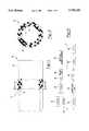
- FIG. 1is a side sectional view of the three-layered fuel pipe of the present invention
- FIG. 2is a cross-sectional view of FIG. 1 along lines 2--2;
- FIG. 3is a schematic diagram of the process for the method of preparing the fuel pipe of the present invention.
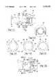
- FIG. 4is a cross-sectional view of the multi-inlet extrusion die used in the method of preparing the fuel pipe of the present invention
- FIG. 5is a cross-sectional view taken along the lines 5--5 of FIG. 4;
- FIG. 6is a cross-sectional view of the interior of the multi-inlet extrusion die taken along the lines 6--6 of FIG. 7;
- FIG. 7is a cross-sectional view taken along the lines of 7--7 of FIG. 6;
- FIG. 8is a cross-sectional view taken along the lines 8--8 of FIG. 6;
- FIG. 9is a cross-sectional view taken along the lines 9--9 of FIG. 6;
- FIG. 10is a cross-sectional view taken along the lines 10--10 of FIG. 6;
- FIG. 11is a cross-sectional view of the center extrusion die that is a part of the multi-inlet extrusion die of FIG. 4;
- FIG. 12is a cross-sectional view taken along the lines 12--12 of FIG. 11;
- FIG. 13is a cross-sectional view taken along the lines 13--13 of FIG. 11;
- FIG. 14is a cross-sectional view taken along the lines 14--14 of FIG. 11;
- FIG. 15is a cross-sectional view taken along the lines 15--15 of FIG. 11;
- FIG. 16is a cross-sectional view of the outer extrusion die which is a portion of the coextrusion multi-inlet die of FIG. 4;
- FIG. 17is a cross-sectional view taken along the lines 17--17 of FIG. 16;
- FIG. 18is a cross-sectional view taken along the lines 18--18 of FIG. 16;
- FIG. 19is a cross-sectional view taken along the lines 19--19 of FIG. 16;
- FIG. 20is a cross-sectional view taken along the lines 20--20 of FIG. 16.
- FIG. 21is a cross-sectional view of the cross-head die as schematically shown in FIG. 3.
- the present inventionis concerned with a method of preparing a fluoropolymer composite such as a pipe or tube.
- a fluoropolymer compositesuch as a pipe or tube.
- the fluoropolymerbe a multi-layered fluoropolymer.
- the inner fluoropolymer layerhave electrostatic discharge resistance and the entire fluoropolymer layer have hydrocarbon evaporative emission resistance.
- the electrostatic discharge resistanceis obtained preferably by making the fluoropolymer layer a conductive fluoropolymer. In this fashion, the electrostatic charge (electricity) that may be generated during the flow of fuel or other fluids through the pipe or tube can be carried to ground.
- the polymers, e.g. fluoropolymers, that may be utilizedare any of the available fluoropolymers, many of which are commercially available.
- Suitable fluoropolymersinclude, but are not limited to, ethylene-tetrafluoroethylene (ETFE), ethylene-chlorotrifluoroethylene (ECTFE), fluorinated ethylenepropylene (FEP), perfluoroalkoxy (PFA), polyvinylfluoride (PVF), polyvinylidene fluoride (PVDF), tetrafluoroethylene-hexafluoropropylene-vinylidenefluoride (THV), polychlorotrifluoroethylene (PCTFE), polytetrafluoroethylene (PTFE).
- ETFEethylene-tetrafluoroethylene
- ECTFEethylene-chlorotrifluoroethylene
- FEPfluorinated ethylenepropylene
- PFAperfluoroalkoxy
- PVFpolyviny
- fluoropolymersare those that are prepared from perfluorinated ⁇ -fluoroolefin monomers containing hydrogen atoms as well as fluorine atoms.
- the ⁇ -fluoroolefinhas 2-6 carbon atoms.
- Typical ⁇ -fluoroolefinsmay be perfluorinated as hexafluoropropene, perfluorobutene, perfluoroisobutene, and the like; as hydrogen-containing ⁇ -fluoroolefins such as trifluoroethylene, vinylidene fluoride, vinyl fluoride, pentafluoropropane, and the like; as halogencontaining ⁇ -fluoroolefins such as trifluorochloroethylene, 1,1-difluoro-2,2 dichloroethylene, 1,2-difluoro-1,2 dichloroethylene, trifluorobromoethylene and the like; and as perfluoroalkoxyethylene polymers.
- the most preferred fluoropolymeris ETFE sold under the trademark Tefzel® (trademark of DuPont).
- the layer of fluoropolymer that is to be conductive in order to carry away the electrostatic dischargecan generally be made conductive in a well known manner. This conductivity can occur by adding conductive particles to the fluoropolymer resin prior to processing.
- the electrically conductive particles incorporated into fluoropolymersare described in U.S. Pat. No. 3,473,087, hereby incorporated by reference.
- Suitable conducting materialswould be carbon black in the amount of 0.1-10 weight percent of the total fluoropolymer layer, preferably 0.1-2 weight percent. The carbon black is blended with the fluoropolymer prior to the extrusion step.
- Conductive fluoropolymer resinis likewise commercially available.
- the fluorinated polymerbe extruded by a melt extrusion technique where the first layer would be a conductive fluoropolymer and co-extruded with it would be the second layer on top of the first layer, wherein the second layer is a fluoropolymer without the conducting particles therein.
- thermosetting or thermoplastic elastomer materialOn top of the fluoropolymer layer, integral with it, and chemically bonded to the fluoropolymer layer is an extruded thermosetting or thermoplastic elastomer material.
- the thermosetting elastomer materialcan be a variety of materials.
- Suitable materialswould be those that can be extruded on top of the extruded fluoropolymer pipe or tube including, but not limited to, amide urethane elastomers, chlorinated polyethylene, chloroprene, chlorosulfonated polyethylene, copolyether ester, epichlorohydrin, ethylene acrylic, ethylene propylene, fluoroelastomer, perfluoroelastomer, fluorosilicone, hydrocarbon elastomers, hydrogenated nitrile butyl, isobutylene isoprene, isoprene, nitrile, polyacrylate, polybutadiene, polyester urethane, polyether urethane, polynorborene, polysulfide, polyurethanes, propylene oxide, silicone, styrene butadiene, styrenic elastomer, and thermoplastic elastomers.
- the most preferred thermosetting elastomeris VA
- Cross-linking and adhesion of the layerscan occur through a number of extrusion techniques.
- the preferred methodutilizes an autoclave amine cure system, with temperature and pressure at 320° F. and 80 PSI, respectively.
- Another methodutilizes a continuous autoclave and salt bath with temperature and pressure at 400°-500° F. and 1 atm, respectively. Still other methods can also be used.
- the end product that is producedis the multi-layered fluoropolymer having a thermosetting or thermoplastic elastomer material 16 chemically bonded on top 10 as shown in FIGS. 1 and 2.
- the conductive layer 12is co-extruded with the non-conductive layer 14.
- the conductive particles(not shown) are present in the layer 12.
- a braided reinforcing materialcan be placed between the layers to provide added strength to the tube.
- This reinforcing materialmay be layered in between the fluoropolymer layer and the thermosetting or thermoplastic elastomer layer, or in a preferred embodiment, may be layered on top of the composite tube, with an added layer of the thermosetting or thermoplastic elastomer on top.
- the fluoropolymerPrior to the extruding of the top thermosetting or thermoplastic elastomer layer 10, the fluoropolymer can be activated.
- the outer portion of layer 14 which is to come into contact with the layer 10may have its surface activated by plasma discharge or corona discharge.
- the fluoropolymer layer 14subjected to a charged gaseous atmosphere that is formed by electrically ionizing a gas which contacts the substrate 14. This serves to increase the chemical bond between the layers. It is most preferred that the plasma impinge upon 360° of the fluoropolymer tube.
- there is a first stage mixed gas plasma electrode dischargewhere approximately 270° of the tube is subjected to the mixed gas plasma discharge.
- the tubeis anywhere from about 0.05 to 3 inches, preferably 0.1 to 0.5 inches from the electrode as the tube passes through the mixed gas plasma electrode discharge. Thereafter, within approximately 3 inches to 3 feet, preferably 6 inches to 18 inches from the first mixed gas plasma discharge device, the tube comes in contact with a second stage mixed gas plasma discharge placed on the opposite side from the first side, where again the tube is subjected to approximately a 270° contact around the tube with the mixed gas plasma discharge. In this fashion, the entire circumference of 360° of the tube is subjected to activation by mixed gas plasma discharge.
- any conventional mixed gas plasma discharge equipmentcan be used.
- One such deviceis available from Enercon Dyne-A-Mite, Model B12, which uses an air blown electrical arc to form the mixed gas treatment plasma.
- there are four separate mixed gas plasma discharge headsmaking up four separate stages which are in the open air, at ambient temperature and pressure.
- Each mixed gas plasma discharge head of the Enercon deviceeach trapezoidal in shape, has a pair of wire electrodes (0.065 inches diameter) in the same horizontal plane separated by a gap of 0.35 inches with an overall length from the end of one wire electrode to the end of the second wire electrode of 1.9 inches.
- closed chamber electrode discharge devicescould be utilized.
- a pair of oppositely charged (positive and negative electrodes)may be utilized by passing a current therebetween, thereby ionizing a gas.
- the substratecan pass through the electric field which has ionized the gas.
- This gasmay be altered by supplying additional gases to the chamber such as oxygen, nitrogen or other reactive gases such as carbon monoxide, fluorinated gases, carbon dioxide, hydrogen fluoride, carbon tetrafluoride, ammonia, and the like.
- the chambermay be operated at vacuum pressure such as from 0.01 to 100 torr (1 atmosphere equals 760 torr).
- a coextrusion die(FIG. 21) is used for high production rates. Therefore, the extruded tube as it passes through the mixed gas plasma discharge stage moves at a high constant rate. Preferably, the rate is from 1 to 150 linear feet per minute (FPM), preferably 15 to 60 FPM.
- the Enercon devicehas a treatment area for the mixed gas plasma discharge with a size of about 21/2 inches by 2 inches per head.
- the activated tubeis not significantly hot to the touch, but is perhaps 10° or 20 ° F. over ambient temperature. This increases the safety in manufacturing the fuel tube or pipe.
- thermosetting or thermoplastic elastomeris extruded through the cross-head die as shown in FIG. 21 and schematically in FIG. 3.
- a curing agentmay be added prior to layering on top of the fluoropolymer.
- the addition of the curing agentserves to increase the strength of the chemical bond between the layers.
- the cross-head dieis at an extrusion temperature sufficient to soften the thermosetting elastomer material. Generally, the temperature is significantly less than the extrusion temperature of the fluorinated plastic.
- the operative temperature for the cross-head diewould range from about 100° to about 500° F., preferably 120° to about 200° F., with screw rotations per minute (RPM) of 10 to 100 RPM, preferably 20 to 60 RPM, with a line speed of approximately 5 to 100 feet per minute, preferably 15 to 70 feet per minute.
- RPMscrew rotations per minute
- the Enercon deviceis preferably operated at an output of 15,000 volts with 30 milliamps plasma per electrode with 2 electrode stages being employed.
- the wattage that is applied to the electrodes in order to ionize the gascan vary substantially.
- the wattagemay vary from 250 joules/sec to 600 joules/sec when the tube being treated is moving about 25 sq. inches/min. (assuming 1 inch outer diameter tube, 12 inches long), i.e. about 10 to 24 joules per linear foot of tube.
- various functional groupssuch as carbonyl, carboxyl, hydroxyl groups and others may be inserted into the molecular structure of the substrate surface. These groups can provide sites for potential chemical bonding with other materials by way of secondary interactions such as hydrogen bonding, van der Waal's interactions, and others. These interactions may occur between the substrate and groups present in the molecular make-up of the applied polymer layer, or between the substrate and additives contained within the applied polymer layer (such as curing agents). These interactions achieve a chemical bond between the substrate and second layer.
- thermosetting materialssuch as ethylene-acrylic elastomer (VAMAC®) may utilize amine curing agents such as triethylene tetramine, which, along with ethylene-acrylic elastomer (VAMAC®) are capable of forming hydrogen bonds with the activated substrate surface.
- amine curing agentssuch as triethylene tetramine
- VAMAC®ethylene-acrylic elastomer
- Other substitutessuch as nylons and urethanes already have functional groups present in their molecular structure such that activation of the substrate is unnecessary in order to effect this chemical bonding with the applied polymer layer.
- Curing agentssuch as amines react with carboxyl curing sites of a neat polymer matrix to form amide crosslinks.
- curing agents present at the interfacemay react with chemical groups in the substrate surface forming covalent bonds to the substrate. These linkages may further react to the applied thermoset/polymer layer.
- FIG. 1is a side sectional view of a three-layered fuel pipe.
- a two-layered pipemay also be utilized in which there is a single, rather than double, fluoropolymer layer.
- FIG. 2is a cross-sectional view of a three-layered pipe. Again, a two-layered pipe may also be utilized.
- the schematic diagram of FIG. 3indicates that coextrusion takes place in the coextrusion die 20 from extruders 22 and 24. After the formed tube leaves die 20, it then enters into die 26 which is in the entrance-way to the vacuum water-cooled chamber 28. The temperature of the water is room temperature. The tube may then be exposed to the mixed gas plasma discharge 32 schematically show in FIG. 3.
- the activated fluoropolymer substrateis subjected to an extrusion of a thermosetting elastomer from extruder 34.
- the fluoropolymer inner layerpasses through a cross-head die for sizing at reference numeral 36.
- the composite tubeis cooled by vacuum cooler 38.
- the tubeis pulled axially through the vacuum cooler by puller 40 and thereafter is cut by cutter 42 to the desired size.
- FIG. 4shows three inlet lines, it is most preferred that a two inlet coextrusion die be utilized when two coextruded layers of fluorinated polymers are prepared, one being the conductive layer and the other being a non-conductive layer.
- a commercially available tube-forming extrusion diecan be used.
- the die assembly 50 shown in FIG. 4includes a die housing 52 having an inner die member 56, a center die member 58 and an outer die member 60 as the main structural members.
- the die members 56, 58 and 60are concentric and generally cylindrically-shaped extrusion die members.
- Throughbore 54extends along axis "A" of the die assembly 50.
- the die members 56, 58 and 60are held together by a bolt or pin 62 or the like which extends through the orifice 64.
- the extrusion die members 56, 58 and 60have inlets 70, 72 and 74, respectively, extending inwardly from the outer periphery of the die housing 50 to the associated die member.
- the inlet 70preferably extends to a semi-circumferential distribution channel 80, through which extrusion material is passed for distribution to the extrusion end 76 of the die assembly 50, as described in greater detail herein below.
- the distribution channel 80is in fluid communication with a pair of axial distribution channels 82.
- the axial distribution channels 82are preferably disposed symmetrically around the inner die member 56 and extend therealong toward the extrusion end 76.
- Each axial distribution channel 82is in fluid communication with a pair of branch distribution channels 84. As illustrated, the branch distribution channels 84 extend around the inner die member 56 in a generally semi-circumferential manner. The branch distribution channels 84 are in fluid communication with four (4) axial distribution channels 86.
- the axial distribution channels 86extend along axis "A" of the inner die member 56 toward the extrusion end 76.
- the channels 86are in fluid communication with a plurality of branch distribution channels 90, which extend around the inner die member 56 in a partial circumferential manner, as best shown in FIG. 8.
- the distribution channels 90are in fluid communication with eight (8) axial distribution channels 92 (only four of which are specifically illustrated in FIG. 6), which also extend along axis "A" toward the extrusion end 76.
- the axial distribution channels 92are in fluid communication with a plurality of generally screw-shaped channels 94 disposed around the extrusion end 76 in a spiral manner.
- extrusion materialenters the inlet 70 and travels to the inner die member 56.
- the extrusion materialsplits and enters the axial distribution channels 82.
- the materialtravels along the channels 82 and splits again at the branch distribution channels 84.
- the extrusion materialthen enters the axial distribution channels 86 and travels therealong to the branch distribution channels 90, where the material splits again and enters the eight axial distribution channels 92.
- the extrusion materialenters the screw-shaped channels 94.
- These screw-shaped channels 94function to provide even distribution and good uniformity of the extrusion material during the extrusion process.
- FIGS. 11 and 15there are shown various cross-sections of the center die member 58.
- Extrusion materialenters the center die member 58 through the inlet 72 (as best shown in FIG. 1).
- the inlet 72preferably extends to a semi-circumferential distribution channel 100, through which extrusion material is passed for distribution to the extrusion end 76', as described in greater detail herein below.
- the distribution channel 100is in fluid communication with a pair of axial distribution channels 102.
- the axial distribution channels 102are preferably disposed symmetrically around the center die member 58 and extend therealong toward the extrusion end 76'.
- each axial distribution channel 102is in fluid communication with a branch distribution channel 104.
- the branch distribution channels 104extend around the center die member 58 in a generally semi-circumferential manner.
- the channels 104are in fluid communication with four (4) axial distribution channels 106.
- the axial distribution channels 106extend along the center die member 58 toward the extrusion end 76'.
- the channels 106are in fluid communication with a plurality of branch distribution channels 110, which extend around the center die member 58 in a partial circumferential manner, as best shown in FIG. 13.
- the distribution channels 110are in fluid communication with eight (8) axial distribution channels 112 (only four of which are specifically illustrated in FIG. 11), which also extend along the member 58 toward the extrusion end 76'.
- the axial distribution channels 112are in fluid communication with a plurality of generally screw-shaped channels 114 disposed around the extrusion end 76' in a spiral manner.
- extrusion materialenters the inlet 72 and travels to the center die member 58.
- the extrusion materialsplits and enters the axial distribution channels 102.
- the materialtravels along the channels 102 and splits again at the branch distribution channels 104.
- the extrusion materialthen enters the axial distribution channels 106 and travels therealong to the branch distribution channels 110, where the material splits again and enters the eight axial distribution channels 112.
- the extrusion materialenters the screw-shaped channels 114.
- these screw-shaped channels 114therefore function to provide even distribution and good uniformity of the extrusion material during the extrusion process.
- extrusion materialenters the outer die member 60 through the inlet 74.
- the inlet 74preferably extends to a trough 120, which is connected to a generally semi-circumferential distribution channel 122, through which extrusion material is passed for distribution to the extrusion end 76", as described in greater detail herein below.
- the distribution channel 122is preferably in fluid communication with a pair of axial distribution channels 124 (only one of which is shown in FIG. 16).
- the axial distribution channels 124are preferably disposed symmetrically around the outer die member 60 and extend therealong toward the extrusion end 76".
- each axial distribution channel 124is in fluid communication with a branch distribution channel 126.
- the branch distribution channels 126extend around the outer die member 60 in a generally semi-circumferential manner.
- the branch distribution channels 126are in fluid communication with four (4) axial distribution channels 128.
- the axial distribution channels 128extend along the outer die member 60 toward the extrusion end 76".
- the channels 128are in fluid communication with a plurality of branch distribution channels 130, which extend around the outer die member 60 in a partial circumferential manner, as best shown in FIG. 18.
- the distribution channels 130are in fluid communication with eight (8) axial distribution channels 132 (only four of which are specifically illustrated in FIG. 16), which also extend along the die member 60 toward the extrusion end 76".
- the axial distribution channels 132are in fluid communication with a plurality of generally screw-shaped channels 134 disposed around the extrusion end 76" in a spiral manner.
- extrusion materialenters the inlet 74 and travels to the trough 120 of the outer die member 60.
- the extrusion materialsplits and enters the axial distribution channels 124.
- the materialtravels along the channels 124 and splits again at the branch distribution channels 126.
- the extrusion materialthen enters the axial distribution channels 128 and travels therealong to the branch distribution channels 130, where the material splits again and enters the eight axial distribution channels 132.
- the extrusion materialenters the screw-shaped channels 134. As with the inner and center die members, these screw-shaped channels 134 therefore function to provide good distribution and uniformity of the extrusion material during the extrusion process.
- FIG. 21is a cross-section of the cross-head die 36 schematically shown in FIG. 3.
- Extruder 34 having auger 138passes material into inlet 140 of the die housing 142 which is held together by four axial screws 144 and vertical screws 146.
- the fluoropolymer tube 148moves in axial fashion through the die housing 142 so that the thermosetting elastomer material can be extruded around it resulting in the composite tube 150 exiting from the housing.
- the thermosetting elastomer materialpasses through inlet 140 and moves around channel 152.
- the desired final outer diameter of the thermosetting elastomer materialis controlled by the die 154.
- the housingis heated by elements 156.
- the fuel line or pipe of the present inventionis designed to carry hydrocarbon fuels that are generally used in vehicles such as automobiles, trucks, airplanes, locomotives, and the like.
- the fuelis generally heavy in hydrocarbon materials such as propane, butane and aromatics, such as benzene, toluene and other combustible organic materials.
- the combined laminate or compositetherefore prevents the escape of fuel vapors from the fuel line.
- Other fuelssuch as alcohol-based fuels may also be carried in the fuel pipe of the present invention.
- other hydrocarbon-based fluidssuch as hydraulic fluids may likewise be utilized in conjunction with the pipe of the present invention.
- the properties of the pipe of this inventionmake it an excellent choice for general chemical handling.
- thermosetting elastomer or thermoplastic elastomer materialwhich typically have substantially lower extrusion temperatures.
- the surface energy of various treated fluoropolymerswas tested. When a dyne solution is placed on a material surface and wets out, that indicates that the material has a higher surface energy than the dyne solution. If the drop "beads up," the material has a lower surface energy than the dyne solution.
- the use of the dyne solutionsis a technique for determining the surface energy of materials.
- Various sampleswere prepared of fluoropolymer substrates. Each of the substrates were subjected to a dyne solution identified as ethyl Cello-Solve-Formamide (Trademark of Corotec of Connecticut, U.S.A.).
- the sample plaqueswere wiped clean with a dry cloth to remove surface contamination. Solvent was not used to avoid any surface effects from the residue.
- the dyne solutionwas applied in a single side-stroke of the brush to leave a 3/4 inch by 1 inch patch of solution. Measurements were taken on both treated and untreated samples. The values recorded represent solution which held in a continuous film for greater than 2 seconds.
- Treated sampleswere prepared by sweeping the discharge head of the Enercon-Dyne-A-Mite device. Treated samples were prepared by sweeping the discharge head across the plaque at a rate of 1/4 inch to 1/2 inch away from the sample surface. Two passes were made to ensure complete coverage. Listed below are the test results for the samples tested.
- sample A and sample BTwo 4" ⁇ 4" ⁇ 0.010" sheets of extruded ETFE (DuPont Tefzel® 200) were labeled as sample A and sample B.
- Sample Bwas exposed for approximately 5 seconds to a charged gaseous atmosphere as previously described and then combined with a VAMAC® layer and clamped as with sample A. Both samples were placed in a circulating air oven at 180° C. for 30 minutes to cure the thermosetting layer. Samples were then removed and allowed to cool at room temperature for 30 minutes. Samples were removed from clamps and cut into strips using an ASTM 1/8" ⁇ 6" die and Arbor press.
Landscapes
- Engineering & Computer Science (AREA)
- Mechanical Engineering (AREA)
- General Engineering & Computer Science (AREA)
- Physics & Mathematics (AREA)
- Plasma & Fusion (AREA)
- Manufacturing & Machinery (AREA)
- Extrusion Moulding Of Plastics Or The Like (AREA)
Abstract
Description
______________________________________ Initial (E.sub.S - After Treatment Sample Surf. Energy) (E.sub.S - Surf. Energy) ______________________________________ KYNAR 740.sup.1 42,41,42 44,45,44 HYLAR 460.sup.2 45,46,45 64,58,60 HALAR 500.sup.3 34,35,34 40,37,39 TEFZEL 200.sup.4 L30,L30,34,34,33 ______________________________________ .sup.1 KYNAR 740 is a trademark of Atochem of North America for PVDF. .sup.2 HYLAR 460 is a trademark of Ausimont of Morristown, New Jersey for PVDF. .sup.3 HYLAR 500 is a trademark of Ausimont of Morristown, New Jersey for ECTFE. .sup.4 TEFZEL 200 is a trademark of DuPont of Wilmington, Delaware for ETFE. L30
______________________________________ Average Maximum Standard Sample Load (Newtons) Deviation ______________________________________ Sample A 4.5 N 0.8 No exposure Sample B 28.5N 5 Exposed to charged gaseous atmosphere ______________________________________
Claims (10)
Priority Applications (5)
| Application Number | Priority Date | Filing Date | Title |
|---|---|---|---|
| US08/265,679US5759329A (en) | 1992-01-06 | 1994-06-24 | Fluoropolymer composite tube and method of preparation |
| US08/403,303US5958532A (en) | 1992-01-06 | 1995-03-14 | Fluoropolymer composite tube and method of preparation |
| US08/707,663US5916404A (en) | 1992-01-06 | 1996-09-04 | Fluoropolymer composite tube and method of preparation |
| US09/638,472US6517657B1 (en) | 1992-01-06 | 2000-08-14 | Fluoropolymer composite tube and method of preparation |
| US10/354,374US20030168157A1 (en) | 1992-01-06 | 2003-01-30 | Fluoropolymer composite tube and method of preparation |
Applications Claiming Priority (3)
| Application Number | Priority Date | Filing Date | Title |
|---|---|---|---|
| US81730492A | 1992-01-06 | 1992-01-06 | |
| US8304293A | 1993-06-24 | 1993-06-24 | |
| US08/265,679US5759329A (en) | 1992-01-06 | 1994-06-24 | Fluoropolymer composite tube and method of preparation |
Related Parent Applications (1)
| Application Number | Title | Priority Date | Filing Date |
|---|---|---|---|
| US8304293AContinuation-In-Part | 1992-01-06 | 1993-06-24 |
Related Child Applications (2)
| Application Number | Title | Priority Date | Filing Date |
|---|---|---|---|
| US08/403,303DivisionUS5958532A (en) | 1992-01-06 | 1995-03-14 | Fluoropolymer composite tube and method of preparation |
| US08/707,663Continuation-In-PartUS5916404A (en) | 1992-01-06 | 1996-09-04 | Fluoropolymer composite tube and method of preparation |
Publications (1)
| Publication Number | Publication Date |
|---|---|
| US5759329Atrue US5759329A (en) | 1998-06-02 |
Family
ID=26768883
Family Applications (2)
| Application Number | Title | Priority Date | Filing Date |
|---|---|---|---|
| US08/265,679Expired - LifetimeUS5759329A (en) | 1992-01-06 | 1994-06-24 | Fluoropolymer composite tube and method of preparation |
| US08/403,303Expired - LifetimeUS5958532A (en) | 1992-01-06 | 1995-03-14 | Fluoropolymer composite tube and method of preparation |
Family Applications After (1)
| Application Number | Title | Priority Date | Filing Date |
|---|---|---|---|
| US08/403,303Expired - LifetimeUS5958532A (en) | 1992-01-06 | 1995-03-14 | Fluoropolymer composite tube and method of preparation |
Country Status (1)
| Country | Link |
|---|---|
| US (2) | US5759329A (en) |
Cited By (57)
| Publication number | Priority date | Publication date | Assignee | Title |
|---|---|---|---|---|
| US6159320A (en)* | 1998-02-06 | 2000-12-12 | Tams; F. Randy | Method and apparatus for manufacturing paint rollers |
| US6207239B1 (en) | 1998-12-16 | 2001-03-27 | Battelle Memorial Institute | Plasma enhanced chemical deposition of conjugated polymer |
| US6207238B1 (en) | 1998-12-16 | 2001-03-27 | Battelle Memorial Institute | Plasma enhanced chemical deposition for high and/or low index of refraction polymers |
| US6217947B1 (en) | 1998-12-16 | 2001-04-17 | Battelle Memorial Institute | Plasma enhanced polymer deposition onto fixtures |
| US6224948B1 (en) | 1997-09-29 | 2001-05-01 | Battelle Memorial Institute | Plasma enhanced chemical deposition with low vapor pressure compounds |
| US6228436B1 (en) | 1998-12-16 | 2001-05-08 | Battelle Memorial Institute | Method of making light emitting polymer composite material |
| US6228434B1 (en) | 1998-12-16 | 2001-05-08 | Battelle Memorial Institute | Method of making a conformal coating of a microtextured surface |
| US6268695B1 (en) | 1998-12-16 | 2001-07-31 | Battelle Memorial Institute | Environmental barrier material for organic light emitting device and method of making |
| US6274204B1 (en) | 1998-12-16 | 2001-08-14 | Battelle Memorial Institute | Method of making non-linear optical polymer |
| US6358570B1 (en) | 1999-03-31 | 2002-03-19 | Battelle Memorial Institute | Vacuum deposition and curing of oligomers and resins |
| US6413645B1 (en) | 2000-04-20 | 2002-07-02 | Battelle Memorial Institute | Ultrabarrier substrates |
| EP1132492A3 (en)* | 2000-03-08 | 2002-07-17 | Wipak Walsrode GmbH & Co. KG | Web-shaped plasma-processed materials |
| US6428866B1 (en)* | 1995-03-01 | 2002-08-06 | Degussa-Huels Aktiengesellschaft | Multilayer plastic composition having an electrically conductive inner layer |
| US6492026B1 (en) | 2000-04-20 | 2002-12-10 | Battelle Memorial Institute | Smoothing and barrier layers on high Tg substrates |
| US6506461B2 (en) | 1999-03-31 | 2003-01-14 | Battelle Memorial Institute | Methods for making polyurethanes as thin films |
| US6514650B1 (en) | 1999-09-02 | 2003-02-04 | Xerox Corporation | Thin perfluoropolymer component coatings |
| US6517657B1 (en)* | 1992-01-06 | 2003-02-11 | Pilot Industries, Inc. | Fluoropolymer composite tube and method of preparation |
| US6540862B1 (en) | 1999-01-28 | 2003-04-01 | Meadwestvaco Corporation | Method and apparatus for enhancing film adhesion when extruding polyethylene terephthalate onto paperboard |
| US6548912B1 (en) | 1999-10-25 | 2003-04-15 | Battelle Memorial Institute | Semicoductor passivation using barrier coatings |
| USRE38087E1 (en)* | 1993-09-10 | 2003-04-22 | Tokai Rubber Industries, Ltd. | Fuel hose and method of its production |
| EP1132148A3 (en)* | 2000-03-08 | 2003-04-23 | Wipak Walsrode GmbH & Co. KG | Process for activating the surface of a web-like material |
| EP1132195A3 (en)* | 2000-03-08 | 2003-04-23 | Wipak Walsrode GmbH & Co. KG | Surface treatment or coating of strips using an atmospheric, non-transferred arc plasmatron |
| US6570325B2 (en) | 1998-12-16 | 2003-05-27 | Battelle Memorial Institute | Environmental barrier material for organic light emitting device and method of making |
| US6573652B1 (en) | 1999-10-25 | 2003-06-03 | Battelle Memorial Institute | Encapsulated display devices |
| US20030113464A1 (en)* | 2001-08-08 | 2003-06-19 | Tatsuo Fukushi | Process for preparing a multi-layer article having a fluoroplastic layer and an elastomer layer |
| US20030168157A1 (en)* | 1992-01-06 | 2003-09-11 | Kuenzel Kenneth J. | Fluoropolymer composite tube and method of preparation |
| US6623861B2 (en) | 2001-04-16 | 2003-09-23 | Battelle Memorial Institute | Multilayer plastic substrates |
| WO2004076155A1 (en)* | 2003-02-28 | 2004-09-10 | Krauss-Maffei Kunststofftechnik Gmbh | Method for producing multi-component plastic moulded parts by treating the pre-injection moulded parts with plasma |
| US6866901B2 (en) | 1999-10-25 | 2005-03-15 | Vitex Systems, Inc. | Method for edge sealing barrier films |
| US20050202646A1 (en)* | 1999-10-25 | 2005-09-15 | Burrows Paul E. | Method for edge sealing barrier films |
| US20070049155A1 (en)* | 2005-08-25 | 2007-03-01 | Vitex Systems, Inc. | Encapsulated devices and method of making |
| US7186465B2 (en) | 1998-11-02 | 2007-03-06 | 3M Innovative Properties Company | Transparent conductive oxides for plastic flat panel displays |
| US20070065616A1 (en)* | 2002-04-11 | 2007-03-22 | Fauble Michael K | Fuel filler hose |
| US20070194481A1 (en)* | 2006-02-23 | 2007-08-23 | Tokai Rubber Industries, Ltd. | Hose production method |
| US20070246867A1 (en)* | 2006-04-20 | 2007-10-25 | Nelson Kevin P | Process for introducing an additive into a polymer melt |
| US7291369B2 (en) | 2001-10-03 | 2007-11-06 | 3M Innovative Properties Company | Multi-layer articles including a fluoroelastomer layer and a barrier layer and method of making the same |
| US20080035228A1 (en)* | 2006-08-14 | 2008-02-14 | Robert Bentley | Bio-pharmaceutical hose |
| US20080257475A1 (en)* | 2002-08-17 | 2008-10-23 | 3M Innovative Properties Company | Flexible electrically conductive film |
| US7510913B2 (en) | 2003-04-11 | 2009-03-31 | Vitex Systems, Inc. | Method of making an encapsulated plasma sensitive device |
| US20090170677A1 (en)* | 2007-04-25 | 2009-07-02 | Seamless Technologies, Llc | Tubular knit fabric having alternating courses of sliver fiber pile and cut-pile for paint roller covers |
| US20090303602A1 (en)* | 2008-06-05 | 2009-12-10 | Bright Clark I | Ultrathin transparent emi shielding filter |
| US7648925B2 (en) | 2003-04-11 | 2010-01-19 | Vitex Systems, Inc. | Multilayer barrier stacks and methods of making multilayer barrier stacks |
| US20100089621A1 (en)* | 2006-12-28 | 2010-04-15 | Walter Stoss | Nucleation layer for thin film metal layer formation |
| US20100219262A1 (en)* | 2005-10-11 | 2010-09-02 | Meadwestvaco Corp. | Fragrance product, dispenser, and dispenser assembly |
| US7905980B2 (en) | 2007-04-25 | 2011-03-15 | Seamless Technologies, Llc | Method of manufacturing paint roller covers from a tubular fabric sleeve |
| US8590338B2 (en) | 2009-12-31 | 2013-11-26 | Samsung Mobile Display Co., Ltd. | Evaporator with internal restriction |
| US8882957B2 (en) | 2007-04-25 | 2014-11-11 | Seamless Technologies, Llc | Methods of manufacturing paint roller covers from a tubular fabric sleeve |
| US8900366B2 (en) | 2002-04-15 | 2014-12-02 | Samsung Display Co., Ltd. | Apparatus for depositing a multilayer coating on discrete sheets |
| US9184410B2 (en) | 2008-12-22 | 2015-11-10 | Samsung Display Co., Ltd. | Encapsulated white OLEDs having enhanced optical output |
| US20150345670A1 (en)* | 2012-12-28 | 2015-12-03 | Agc Chemicals Americas, Inc. | A Layered Tube For A Hose Assembly |
| US9337446B2 (en) | 2008-12-22 | 2016-05-10 | Samsung Display Co., Ltd. | Encapsulated RGB OLEDs having enhanced optical output |
| US9839940B2 (en) | 2002-04-15 | 2017-12-12 | Samsung Display Co., Ltd. | Apparatus for depositing a multilayer coating on discrete sheets |
| WO2019067985A2 (en) | 2017-09-28 | 2019-04-04 | Saint-Gobain Performance Plastics Corporation | Fuel tubings and methods for making and using same |
| CN109795092A (en)* | 2019-04-03 | 2019-05-24 | 广州市程翔机械有限公司 | A kind of low-penetration fuel pipe extrusion production equipment |
| CN109795091A (en)* | 2019-04-03 | 2019-05-24 | 广州市程翔机械有限公司 | A kind of Fluoroplastic extruder |
| US10807342B2 (en) | 2015-12-15 | 2020-10-20 | Agc Chemicals Americas, Inc. | Layered tube and layer for use in same |
| US10950821B2 (en) | 2007-01-26 | 2021-03-16 | Samsung Display Co., Ltd. | Method of encapsulating an environmentally sensitive device |
Families Citing this family (29)
| Publication number | Priority date | Publication date | Assignee | Title |
|---|---|---|---|---|
| US6378562B1 (en)* | 1992-04-14 | 2002-04-30 | Itt Industries, Inc. | Multi-layer tubing having electrostatic dissipation for handling hydrocarbon fluids |
| US6106914A (en)* | 1997-01-22 | 2000-08-22 | Tokai Rubber Industries, Ltd. | Laminar structure and a hose formed of the laminar structure exhibiting good adhesiveness between adjacent layers |
| DE19834065C2 (en)* | 1997-08-08 | 2003-02-27 | Kaco Gmbh Co | Component from at least one carrier and at least one part fastened to it and method for producing a connection between a carrier and a part of such a component |
| DE19906746A1 (en)* | 1998-02-26 | 1999-11-04 | Tokiwa Chem Ind Ltd | Protective tube for Bowden cable actuator used in automobiles as e.g. bonnet, petrol cap or boot release |
| US6287657B1 (en)* | 1998-11-12 | 2001-09-11 | Telcordia Technologies, Inc. | All-plastic air feeder pipe |
| EP1099532B1 (en)* | 1999-10-28 | 2004-06-16 | Bridgestone Corporation | Method of surface treating and laminating a fluorine resin |
| GB0006333D0 (en)* | 2000-03-16 | 2000-05-03 | Raychem Ltd | Electrical wire insulation |
| US6682796B2 (en)* | 2000-05-31 | 2004-01-27 | Tokai Rubber Industries, Ltd. | Fuel hose |
| IT1318700B1 (en)* | 2000-09-18 | 2003-08-27 | Ausimont Spa | MULTI-LAYER COMPOSITION INCLUDING FLUOROPOLYMERS AND POLYMERS HYDROGENATED. |
| US7320818B2 (en)* | 2001-03-13 | 2008-01-22 | Ausimont S.P.A. | Multilayers of polyamides and fluorinated copolymers |
| US7396582B2 (en)* | 2001-04-06 | 2008-07-08 | Advanced Cardiovascular Systems, Inc. | Medical device chemically modified by plasma polymerization |
| JP3788612B2 (en)* | 2002-11-22 | 2006-06-21 | 三菱鉛筆株式会社 | Ink container for writing instruments |
| US6742952B1 (en) | 2003-02-28 | 2004-06-01 | Bic Corporation | Transparent or translucent tubular structure |
| GB2405456B (en)* | 2003-08-23 | 2007-10-10 | Petrotechnik Ltd | Improved pipe |
| TWI273087B (en)* | 2003-12-01 | 2007-02-11 | Arkema | Use of a hose based on an irradiation-grafted fluoropolymer for transporting petrol in service station |
| DE602004012064T2 (en)* | 2004-03-25 | 2009-02-26 | Manifattura Tubi Gomma S.P.A., Grisignano Di Zocco | Antistatic hose for liquids |
| US7556067B2 (en)* | 2005-02-17 | 2009-07-07 | Stant Manufacturing Inc. | Fuel tank filler neck assembly |
| FR2886708B1 (en)* | 2005-06-02 | 2007-08-17 | Arkema Sa | USE OF MODIFIED FLUORINE POLYMER FOR THE TRANSPORT OF WATER OR GAS |
| CN101646871A (en)* | 2007-03-07 | 2010-02-10 | 圣戈本操作塑料有限公司 | multilayer tube |
| FR2918067B1 (en)* | 2007-06-27 | 2011-07-01 | Arkema France | COMPOSITE MATERIAL COMPRISING DISPERSED NANOTUBES IN A FLUORINATED POLYMERIC MATRIX. |
| JP4968338B2 (en)* | 2007-08-08 | 2012-07-04 | ダイキン工業株式会社 | Laminated body consisting of fluororesin layer and elastomer layer |
| WO2009085997A1 (en)* | 2007-12-28 | 2009-07-09 | Saint-Gobain Performance Plastics Corporation | Reinforced tube |
| US20110155310A1 (en)* | 2009-12-29 | 2011-06-30 | Cipielewski Stephen B | Braided hose assembly and method of manufacturing same |
| EP2639059B1 (en)* | 2010-11-12 | 2020-01-08 | Daikin Industries, Ltd. | Laminate body |
| US9830797B2 (en) | 2012-12-28 | 2017-11-28 | Eaton Corporation | High pressure hose with polymeric tube |
| WO2014183101A1 (en)* | 2013-05-10 | 2014-11-13 | Agc Chemicals Americas, Inc. | A layered tube and layer for use in same |
| KR102263346B1 (en) | 2013-12-09 | 2021-06-14 | 쓰리엠 이노베이티브 프로퍼티즈 컴파니 | A fluoroelastomer component for contacting ammonia and/or urea |
| CN105371049B (en)* | 2015-12-01 | 2017-11-14 | 无锡琛华复合材料有限公司 | Heavy caliber trenchless repairing method of underground pipeline |
| SG11202112940RA (en) | 2019-05-23 | 2021-12-30 | Entegris Inc | Electrostatic discharge mitigation tubing |
Citations (68)
| Publication number | Priority date | Publication date | Assignee | Title |
|---|---|---|---|---|
| US3017339A (en)* | 1957-01-24 | 1962-01-16 | American Can Co | Method of and apparatus for treating surfaces of extruded thermoplastic tubing with corona discharge |
| CA686119A (en)* | 1964-05-12 | T. Mcbride Richard | Process for imparting adherability to polyfluorocarbon surfaces | |
| US3133854A (en)* | 1960-11-15 | 1964-05-19 | Du Pont | Polyvinyl fluoride laminates and process for making same |
| US3352714A (en)* | 1961-03-13 | 1967-11-14 | Du Pont | Polyfluorocarbon substrate coated with polyamide and method |
| DE1290717B (en)* | 1960-06-15 | 1969-03-13 | Du Pont | Modification of the surface properties of shaped polymer structures |
| US3455774A (en)* | 1965-06-29 | 1969-07-15 | Du Pont | Process of surface treating and laminating perfluorocarbon polymer films and laminated products made thereby |
| US3457139A (en)* | 1966-01-19 | 1969-07-22 | Albert L James | Unheated dry lamination process for producing laminations from thermoplastic and substrates |
| US3473087A (en)* | 1962-05-22 | 1969-10-14 | Raybestos Manhattan Inc | Electrically conductive polytetrafluoroethylene tubing |
| US3507763A (en)* | 1967-12-22 | 1970-04-21 | Du Pont | Method for electrical discharge treatment of organic polymeric materials |
| US3676181A (en)* | 1969-09-16 | 1972-07-11 | Du Pont | Electrical discharge treatment of tetrafluoroethylene/hexafluoropropylene copolymer in acetone |
| US3907955A (en)* | 1972-08-01 | 1975-09-23 | Aeroquip Ag | Process for manufacturing electrically conductive polytetrafluoroethylene tube |
| JPS51119777A (en)* | 1975-04-14 | 1976-10-20 | Nitto Electric Ind Co Ltd | Composite sheet |
| US4035534A (en)* | 1972-09-01 | 1977-07-12 | Raychem Corporation | Heat-shrinkable laminate |
| JPS5358588A (en)* | 1976-11-09 | 1978-05-26 | Asahi Glass Co Ltd | Synthetic resin laminate with exellent weatherability and corrosionresistance |
| US4188426A (en)* | 1977-12-12 | 1980-02-12 | Lord Corporation | Cold plasma modification of organic and inorganic surfaces |
| US4272585A (en)* | 1976-04-06 | 1981-06-09 | Produits Chimiques Ugine Kuhlmann | Process for treating polyvinylidene fluoride and resulting products |
| US4293663A (en)* | 1979-10-23 | 1981-10-06 | Minnesota Mining And Manufacturing Company | Fluoroelastomer/polyepichlorohydrin elastomer articles |
| US4330017A (en)* | 1977-04-22 | 1982-05-18 | Nissan Motor Company, Limited | Rubber hose for automotive fuel line |
| US4343861A (en)* | 1979-10-23 | 1982-08-10 | Minnesota Mining And Manufacturing Company | Fluoroelastomer/polyepichlorohydrin elastomer articles |
| US4353763A (en)* | 1980-05-13 | 1982-10-12 | Henze Gmbh | Method for making pipes, plates or containers from plastic material |
| US4358559A (en)* | 1981-11-19 | 1982-11-09 | Minnesota Mining And Manufacturing Company | Tacky fluoroelastomer compositions |
| US4383131A (en)* | 1978-09-14 | 1983-05-10 | Raychem Limited | Shielded electrical cable joints and terminations and sleeve and method for forming same |
| JPS58114979A (en)* | 1981-12-28 | 1983-07-08 | Hitachi Koki Co Ltd | Print hammer for printer |
| JPS58201613A (en)* | 1982-05-19 | 1983-11-24 | Toagosei Chem Ind Co Ltd | Adhesion of fluoric resin |
| US4564662A (en)* | 1984-02-23 | 1986-01-14 | Minnesota Mining And Manufacturing Company | Fluorocarbon elastomer |
| DE3524631A1 (en)* | 1984-07-10 | 1986-01-16 | Daikin Industries, Ltd., Osaka | POLYMER COMPOSITE HEATING ELEMENT |
| EP0185590A2 (en)* | 1984-12-14 | 1986-06-25 | Shin-Etsu Chemical Co., Ltd. | A method for the preparation of a laminated film |
| US4603712A (en)* | 1985-03-29 | 1986-08-05 | The Gates Rubber Company | Compounded polychloroprene formulation used as an adhesive layer in the manufacture of elastomeric articles |
| US4634615A (en)* | 1984-04-06 | 1987-01-06 | Versteegh Willem M | Heat recoverable coextruded articles |
| US4636272A (en)* | 1985-02-19 | 1987-01-13 | Cordis Corporation | Process for thermally bonding plastic tubes |
| US4654235A (en)* | 1984-04-13 | 1987-03-31 | Chemical Fabrics Corporation | Novel wear resistant fluoropolymer-containing flexible composites and method for preparation thereof |
| US4718568A (en)* | 1985-11-15 | 1988-01-12 | Fabbrica Italiana Serrature Torino Fist | Fuel filler member for vehicles |
| JPS639533A (en)* | 1986-07-01 | 1988-01-16 | Lonseal Corp | Production of interior decorative material |
| US4731156A (en)* | 1987-02-25 | 1988-03-15 | Itt Avionics, A Division Of Itt Corporation | Plasma processes for surface modification of fluoropolymers using ammonia |
| US4743327A (en)* | 1984-06-15 | 1988-05-10 | Cordis Corporation | Adhesive bonding of fluoropolymers |
| US4748204A (en)* | 1985-09-19 | 1988-05-31 | Central Glass Company, Limited | Flexible and melt processable fluororesin |
| US4749610A (en)* | 1986-02-20 | 1988-06-07 | Central Glass Company, Limited | Glass fiber reinforced flexible composite material using soft fluororesin |
| US4758455A (en)* | 1985-07-10 | 1988-07-19 | Handy & Harman Automotive Group Inc. | Composite fuel and vapor tube having increased heat resistance |
| US4770927A (en)* | 1983-04-13 | 1988-09-13 | Chemical Fabrics Corporation | Reinforced fluoropolymer composite |
| GB2204932A (en)* | 1987-05-14 | 1988-11-23 | Usui Kokusai Sangyo Kk | Flexible composite hose |
| US4800109A (en)* | 1986-02-01 | 1989-01-24 | Usui Kokusai Sangyo Kabushiki Kaisha | Flexible composite hose |
| US4826731A (en)* | 1987-05-15 | 1989-05-02 | E. I. Du Pont De Nemours And Company | Dual cured fluoropolymer laminates |
| JPH01154755A (en)* | 1987-12-11 | 1989-06-16 | Furukawa Electric Co Ltd:The | Composite polyolefin pipe and its manufacturing method |
| JPH01174442A (en)* | 1987-12-28 | 1989-07-11 | Toray Silicone Co Ltd | Manufacture of fabric laminate coated with silicone rubber |
| US4887647A (en)* | 1987-07-08 | 1989-12-19 | Tokai Rubber Industries, Ltd. | Hose |
| US4898638A (en)* | 1987-11-26 | 1990-02-06 | Valois S.A. | Method of manufacturing flexible gaskets which withstand chemical agents |
| JPH02107371A (en)* | 1988-06-16 | 1990-04-19 | Hoechst Ag | Method and apparatus for pretreating plastic molded product and molded product |
| US4933060A (en)* | 1987-03-02 | 1990-06-12 | The Standard Oil Company | Surface modification of fluoropolymers by reactive gas plasmas |
| US4943473A (en)* | 1985-05-16 | 1990-07-24 | Chemical Fabrics Corporation | Flexible laminated fluoropolymer-containing composites |
| EP0385731A1 (en)* | 1989-03-01 | 1990-09-05 | Japan Gore-Tex, Inc. | Conductive composite plastics tube |
| US4995028A (en)* | 1982-12-17 | 1991-02-19 | Unisys Corp. | Coated media for optical recording, with soft/hard overcoat |
| DE3930350A1 (en)* | 1989-09-12 | 1991-03-14 | Pahl Gummi Asbest | TUBE |
| US5008340A (en)* | 1988-12-21 | 1991-04-16 | Raychem Corporation | Curable adhesives |
| JPH03114829A (en)* | 1989-09-29 | 1991-05-16 | Shin Etsu Chem Co Ltd | packaging material |
| US5051978A (en)* | 1982-11-30 | 1991-09-24 | Burroughs Corporation | Coated media for optical recording |
| US5056512A (en)* | 1989-06-06 | 1991-10-15 | E. I. Du Pont De Nemours And Company | Multilayered hood with elastomeric neck seal |
| US5059480A (en)* | 1988-12-21 | 1991-10-22 | Raychem Corporation | Curable adhesives |
| US5077115A (en)* | 1990-05-08 | 1991-12-31 | Rogers Corporation | Thermoplastic composite material |
| US5081326A (en)* | 1989-08-07 | 1992-01-14 | Usui Kokusai Sangyo Kaisha Limited | Electroconductive composite tube assembly |
| US5089200A (en)* | 1989-10-06 | 1992-02-18 | E. I. Dupont De Nemours And Company | Process for melt extrusion of polymers |
| EP0479592A2 (en)* | 1990-10-05 | 1992-04-08 | Bridgestone Corporation | Surface treatment of fluorochemical members and preparation of composite products therefrom |
| US5108780A (en)* | 1991-01-28 | 1992-04-28 | Brigham Young University | Enhanced thermoplastic adhesion to fibers by using plasma discharge |
| US5124878A (en)* | 1989-02-02 | 1992-06-23 | Teleflex Incorporated | Coated braided hose method |
| US5141800A (en)* | 1989-02-02 | 1992-08-25 | Chemical Fabrics Corporation | Method of making laminated PTFE-containing composites and products thereof |
| US5170011A (en)* | 1991-09-25 | 1992-12-08 | Teleflex Incorporated | Hose assembly |
| US5284184A (en)* | 1992-04-14 | 1994-02-08 | Itt Corporation | Corrugated multi-layer tubing having at least one fluoroplastic layer |
| US5357005A (en)* | 1991-12-11 | 1994-10-18 | International Business Machines Corporation | Reactive surface functionalization |
| US5500257A (en)* | 1992-01-06 | 1996-03-19 | Pilot Industries, Inc. | Method of preparing a fluoropolymer composite |
Family Cites Families (3)
| Publication number | Priority date | Publication date | Assignee | Title |
|---|---|---|---|---|
| JPS5738272A (en)* | 1980-08-20 | 1982-03-02 | Hitachi Ltd | Inhibitor for noise of elevator |
| JPS62162542A (en)* | 1986-01-13 | 1987-07-18 | 宇部興産株式会社 | Polyinide film with fluoroplastic layer |
| JPS63224943A (en)* | 1987-03-16 | 1988-09-20 | 住友ベークライト株式会社 | Moisture-proof film |
- 1994
- 1994-06-24USUS08/265,679patent/US5759329A/ennot_activeExpired - Lifetime
- 1995
- 1995-03-14USUS08/403,303patent/US5958532A/ennot_activeExpired - Lifetime
Patent Citations (69)
| Publication number | Priority date | Publication date | Assignee | Title |
|---|---|---|---|---|
| CA686119A (en)* | 1964-05-12 | T. Mcbride Richard | Process for imparting adherability to polyfluorocarbon surfaces | |
| US3017339A (en)* | 1957-01-24 | 1962-01-16 | American Can Co | Method of and apparatus for treating surfaces of extruded thermoplastic tubing with corona discharge |
| DE1290717B (en)* | 1960-06-15 | 1969-03-13 | Du Pont | Modification of the surface properties of shaped polymer structures |
| US3133854A (en)* | 1960-11-15 | 1964-05-19 | Du Pont | Polyvinyl fluoride laminates and process for making same |
| US3352714A (en)* | 1961-03-13 | 1967-11-14 | Du Pont | Polyfluorocarbon substrate coated with polyamide and method |
| US3473087A (en)* | 1962-05-22 | 1969-10-14 | Raybestos Manhattan Inc | Electrically conductive polytetrafluoroethylene tubing |
| US3455774A (en)* | 1965-06-29 | 1969-07-15 | Du Pont | Process of surface treating and laminating perfluorocarbon polymer films and laminated products made thereby |
| US3457139A (en)* | 1966-01-19 | 1969-07-22 | Albert L James | Unheated dry lamination process for producing laminations from thermoplastic and substrates |
| US3507763A (en)* | 1967-12-22 | 1970-04-21 | Du Pont | Method for electrical discharge treatment of organic polymeric materials |
| US3676181A (en)* | 1969-09-16 | 1972-07-11 | Du Pont | Electrical discharge treatment of tetrafluoroethylene/hexafluoropropylene copolymer in acetone |
| US3907955A (en)* | 1972-08-01 | 1975-09-23 | Aeroquip Ag | Process for manufacturing electrically conductive polytetrafluoroethylene tube |
| US4035534A (en)* | 1972-09-01 | 1977-07-12 | Raychem Corporation | Heat-shrinkable laminate |
| JPS51119777A (en)* | 1975-04-14 | 1976-10-20 | Nitto Electric Ind Co Ltd | Composite sheet |
| US4272585A (en)* | 1976-04-06 | 1981-06-09 | Produits Chimiques Ugine Kuhlmann | Process for treating polyvinylidene fluoride and resulting products |
| JPS5358588A (en)* | 1976-11-09 | 1978-05-26 | Asahi Glass Co Ltd | Synthetic resin laminate with exellent weatherability and corrosionresistance |
| US4330017A (en)* | 1977-04-22 | 1982-05-18 | Nissan Motor Company, Limited | Rubber hose for automotive fuel line |
| US4188426A (en)* | 1977-12-12 | 1980-02-12 | Lord Corporation | Cold plasma modification of organic and inorganic surfaces |
| US4383131A (en)* | 1978-09-14 | 1983-05-10 | Raychem Limited | Shielded electrical cable joints and terminations and sleeve and method for forming same |
| US4343861A (en)* | 1979-10-23 | 1982-08-10 | Minnesota Mining And Manufacturing Company | Fluoroelastomer/polyepichlorohydrin elastomer articles |
| US4293663A (en)* | 1979-10-23 | 1981-10-06 | Minnesota Mining And Manufacturing Company | Fluoroelastomer/polyepichlorohydrin elastomer articles |
| US4353763A (en)* | 1980-05-13 | 1982-10-12 | Henze Gmbh | Method for making pipes, plates or containers from plastic material |
| US4358559A (en)* | 1981-11-19 | 1982-11-09 | Minnesota Mining And Manufacturing Company | Tacky fluoroelastomer compositions |
| JPS58114979A (en)* | 1981-12-28 | 1983-07-08 | Hitachi Koki Co Ltd | Print hammer for printer |
| JPS58201613A (en)* | 1982-05-19 | 1983-11-24 | Toagosei Chem Ind Co Ltd | Adhesion of fluoric resin |
| US5051978A (en)* | 1982-11-30 | 1991-09-24 | Burroughs Corporation | Coated media for optical recording |
| US4995028A (en)* | 1982-12-17 | 1991-02-19 | Unisys Corp. | Coated media for optical recording, with soft/hard overcoat |
| US4770927A (en)* | 1983-04-13 | 1988-09-13 | Chemical Fabrics Corporation | Reinforced fluoropolymer composite |
| US4564662A (en)* | 1984-02-23 | 1986-01-14 | Minnesota Mining And Manufacturing Company | Fluorocarbon elastomer |
| US4634615A (en)* | 1984-04-06 | 1987-01-06 | Versteegh Willem M | Heat recoverable coextruded articles |
| US4654235A (en)* | 1984-04-13 | 1987-03-31 | Chemical Fabrics Corporation | Novel wear resistant fluoropolymer-containing flexible composites and method for preparation thereof |
| US4743327A (en)* | 1984-06-15 | 1988-05-10 | Cordis Corporation | Adhesive bonding of fluoropolymers |
| DE3524631A1 (en)* | 1984-07-10 | 1986-01-16 | Daikin Industries, Ltd., Osaka | POLYMER COMPOSITE HEATING ELEMENT |
| EP0185590A2 (en)* | 1984-12-14 | 1986-06-25 | Shin-Etsu Chemical Co., Ltd. | A method for the preparation of a laminated film |
| US4636272A (en)* | 1985-02-19 | 1987-01-13 | Cordis Corporation | Process for thermally bonding plastic tubes |
| US4603712A (en)* | 1985-03-29 | 1986-08-05 | The Gates Rubber Company | Compounded polychloroprene formulation used as an adhesive layer in the manufacture of elastomeric articles |
| US4943473A (en)* | 1985-05-16 | 1990-07-24 | Chemical Fabrics Corporation | Flexible laminated fluoropolymer-containing composites |
| US4758455A (en)* | 1985-07-10 | 1988-07-19 | Handy & Harman Automotive Group Inc. | Composite fuel and vapor tube having increased heat resistance |
| US4748204A (en)* | 1985-09-19 | 1988-05-31 | Central Glass Company, Limited | Flexible and melt processable fluororesin |
| US4718568A (en)* | 1985-11-15 | 1988-01-12 | Fabbrica Italiana Serrature Torino Fist | Fuel filler member for vehicles |
| US4800109A (en)* | 1986-02-01 | 1989-01-24 | Usui Kokusai Sangyo Kabushiki Kaisha | Flexible composite hose |
| US4749610A (en)* | 1986-02-20 | 1988-06-07 | Central Glass Company, Limited | Glass fiber reinforced flexible composite material using soft fluororesin |
| JPS639533A (en)* | 1986-07-01 | 1988-01-16 | Lonseal Corp | Production of interior decorative material |
| US4731156A (en)* | 1987-02-25 | 1988-03-15 | Itt Avionics, A Division Of Itt Corporation | Plasma processes for surface modification of fluoropolymers using ammonia |
| US4933060A (en)* | 1987-03-02 | 1990-06-12 | The Standard Oil Company | Surface modification of fluoropolymers by reactive gas plasmas |
| GB2204932A (en)* | 1987-05-14 | 1988-11-23 | Usui Kokusai Sangyo Kk | Flexible composite hose |
| US4826731A (en)* | 1987-05-15 | 1989-05-02 | E. I. Du Pont De Nemours And Company | Dual cured fluoropolymer laminates |
| US4887647A (en)* | 1987-07-08 | 1989-12-19 | Tokai Rubber Industries, Ltd. | Hose |
| US4898638A (en)* | 1987-11-26 | 1990-02-06 | Valois S.A. | Method of manufacturing flexible gaskets which withstand chemical agents |
| JPH01154755A (en)* | 1987-12-11 | 1989-06-16 | Furukawa Electric Co Ltd:The | Composite polyolefin pipe and its manufacturing method |
| JPH01174442A (en)* | 1987-12-28 | 1989-07-11 | Toray Silicone Co Ltd | Manufacture of fabric laminate coated with silicone rubber |
| JPH02107371A (en)* | 1988-06-16 | 1990-04-19 | Hoechst Ag | Method and apparatus for pretreating plastic molded product and molded product |
| US5008340A (en)* | 1988-12-21 | 1991-04-16 | Raychem Corporation | Curable adhesives |
| US5059480A (en)* | 1988-12-21 | 1991-10-22 | Raychem Corporation | Curable adhesives |
| US5124878A (en)* | 1989-02-02 | 1992-06-23 | Teleflex Incorporated | Coated braided hose method |
| US5141800A (en)* | 1989-02-02 | 1992-08-25 | Chemical Fabrics Corporation | Method of making laminated PTFE-containing composites and products thereof |
| EP0385731A1 (en)* | 1989-03-01 | 1990-09-05 | Japan Gore-Tex, Inc. | Conductive composite plastics tube |
| US5056512A (en)* | 1989-06-06 | 1991-10-15 | E. I. Du Pont De Nemours And Company | Multilayered hood with elastomeric neck seal |
| US5081326A (en)* | 1989-08-07 | 1992-01-14 | Usui Kokusai Sangyo Kaisha Limited | Electroconductive composite tube assembly |
| DE3930350A1 (en)* | 1989-09-12 | 1991-03-14 | Pahl Gummi Asbest | TUBE |
| JPH03114829A (en)* | 1989-09-29 | 1991-05-16 | Shin Etsu Chem Co Ltd | packaging material |
| US5089200A (en)* | 1989-10-06 | 1992-02-18 | E. I. Dupont De Nemours And Company | Process for melt extrusion of polymers |
| US5077115A (en)* | 1990-05-08 | 1991-12-31 | Rogers Corporation | Thermoplastic composite material |
| EP0479592A2 (en)* | 1990-10-05 | 1992-04-08 | Bridgestone Corporation | Surface treatment of fluorochemical members and preparation of composite products therefrom |
| US5108780A (en)* | 1991-01-28 | 1992-04-28 | Brigham Young University | Enhanced thermoplastic adhesion to fibers by using plasma discharge |
| US5170011A (en)* | 1991-09-25 | 1992-12-08 | Teleflex Incorporated | Hose assembly |
| US5357005A (en)* | 1991-12-11 | 1994-10-18 | International Business Machines Corporation | Reactive surface functionalization |
| US5500257A (en)* | 1992-01-06 | 1996-03-19 | Pilot Industries, Inc. | Method of preparing a fluoropolymer composite |
| US5554425A (en)* | 1992-01-06 | 1996-09-10 | Pilot Industries, Inc. | Fluoropolymer composite tube and method of preparation |
| US5284184A (en)* | 1992-04-14 | 1994-02-08 | Itt Corporation | Corrugated multi-layer tubing having at least one fluoroplastic layer |
Non-Patent Citations (23)
| Title |
|---|
| "`P-Cap` from Pilot Industries Inc. First Place Winner 1993 Plunkett Awards for Innovation with `Teflon`,"Du Pont Background, Du Pont External Affairs, Wilmington, Delaware. |
| "Du Pont Announces Winners of 1993 Plunkett Awards for Innovation with `Teflon`," Du Pont External Affairs, Wilmington, Delaware, Mar. 1993. |
| Achieving Optimum Bond Strength With Plasma Treatment, George P. Hansen et al., Society of Manufacturing Engineers, Sep. 1989, Paper No. AD 89 537.* |
| Achieving Optimum Bond Strength With Plasma Treatment, George P. Hansen et al., Society of Manufacturing Engineers, Sep. 1989, Paper No. AD 89-537. |
| Cefral Soft, Technical Data, Central Glass Co., Ltd.* |
| Ceramic Coatings: More Than Just Wear Resistant, Edward S. Hamel, ME, Aug. 1986, pp. 30 34.* |
| Ceramic Coatings: More Than Just Wear Resistant, Edward S. Hamel, ME, Aug. 1986, pp. 30-34. |
| Derwent Abstract of JP 62 162542.* |
| Derwent Abstract of JP 62-162542. |
| Derwent Abstract of JP 63 224943.* |
| Derwent Abstract of JP 63-224943. |
| Du Pont Announces Winners of 1993 Plunkett Awards for Innovation with Teflon , Du Pont External Affairs, Wilmington, Delaware, Mar. 1993.* |
| Dyne A Mite Solves Adhesion Problems, Promotional brochure from Enercon Industries Corporation, Menomee Falls, Wisconsin.* |
| Dyne-A-Mite™ Solves Adhesion Problems, Promotional brochure from Enercon Industries Corporation, Menomee Falls, Wisconsin. |
| Gas Plasma Technology and Its Applications, Stephen L. Kaplan and Robert Hollan, Mar. 1987, Plasma Science, Belment, Calif.* |
| P Cap from Pilot Industries Inc. First Place Winner 1993 Plunkett Awards for Innovation with Teflon , Du Pont Background, Du Pont External Affairs, Wilmington, Delaware.* |
| Pilot Industries Wins Top Award for Innovation, Pilot Industries, Inc., Dexter, Michigan.* |
| Pilot Industries Wins Top Plunkett Award, Plastics News, Wilmington, Delaware, 5 Apr. 1993, p. 8.* |
| Plasma Sprayed Coatings, Herbert Herman, Scientific American, Sep. 1988, pp. 112 117.* |
| Plasma Treatment Upgrades Adhesion in Plastic Parts, Stephen L. Kaplan and Peter W. Rose, Plastics Engineering, May 1988, pp. 77 79.* |
| Plasma Treatment Upgrades Adhesion in Plastic Parts, Stephen L. Kaplan and Peter W. Rose, Plastics Engineering, May 1988, pp. 77-79. |
| Plasma-Sprayed Coatings, Herbert Herman, Scientific American, Sep. 1988, pp. 112-117. |
| Properties of Polymers Used in Hose Manufacture, Chapter 16, Hose Technology, Colin W. Evans, Publisher: Applied Science Publisher Ltd., Ripple Rd, Barking, Essex, Eng.* |
Cited By (106)
| Publication number | Priority date | Publication date | Assignee | Title |
|---|---|---|---|---|
| US20030168157A1 (en)* | 1992-01-06 | 2003-09-11 | Kuenzel Kenneth J. | Fluoropolymer composite tube and method of preparation |
| US6517657B1 (en)* | 1992-01-06 | 2003-02-11 | Pilot Industries, Inc. | Fluoropolymer composite tube and method of preparation |
| USRE38087E1 (en)* | 1993-09-10 | 2003-04-22 | Tokai Rubber Industries, Ltd. | Fuel hose and method of its production |
| US6428866B1 (en)* | 1995-03-01 | 2002-08-06 | Degussa-Huels Aktiengesellschaft | Multilayer plastic composition having an electrically conductive inner layer |
| US6627267B2 (en) | 1997-09-29 | 2003-09-30 | Battelle Memorial Institute | Plasma enhanced chemical deposition with low vapor pressure compounds |
| US6224948B1 (en) | 1997-09-29 | 2001-05-01 | Battelle Memorial Institute | Plasma enhanced chemical deposition with low vapor pressure compounds |
| US6656537B2 (en) | 1997-09-29 | 2003-12-02 | Battelle Memorial Institute | Plasma enhanced chemical deposition with low vapor pressure compounds |
| US6159320A (en)* | 1998-02-06 | 2000-12-12 | Tams; F. Randy | Method and apparatus for manufacturing paint rollers |
| US6660118B2 (en) | 1998-02-06 | 2003-12-09 | Paint Sundry Brands, Llc | Method and apparatus for manufacturing paint rollers |
| US7186465B2 (en) | 1998-11-02 | 2007-03-06 | 3M Innovative Properties Company | Transparent conductive oxides for plastic flat panel displays |
| US7276291B2 (en) | 1998-11-02 | 2007-10-02 | 3M Innovative Properties Company | Transparent conductive articles and methods of making same |
| US20110074282A1 (en)* | 1998-11-02 | 2011-03-31 | 3M Innovative Properties Company | Transparent conductive articles and methods of making same |
| US8241752B2 (en) | 1998-11-02 | 2012-08-14 | 3M Innovative Properties Company | Transparent conductive articles and methods of making same |
| US8541942B2 (en) | 1998-11-02 | 2013-09-24 | 3M Innovative Properties Company | Transparent conductive articles and methods of making same |
| US20080008893A1 (en)* | 1998-11-02 | 2008-01-10 | 3M Innovative Properties Company | Transparent conductive articles and methods of making same |
| US6509065B2 (en) | 1998-12-16 | 2003-01-21 | Battelle Memorial Institute | Plasma enhanced chemical deposition of conjugated polymer |
| US6274204B1 (en) | 1998-12-16 | 2001-08-14 | Battelle Memorial Institute | Method of making non-linear optical polymer |
| US20030235648A1 (en)* | 1998-12-16 | 2003-12-25 | Affinito John D. | Method of making molecularly doped composite polymer material |
| US20040009306A1 (en)* | 1998-12-16 | 2004-01-15 | Affinito John D. | Plasma enhanced chemical deposition for high and/or low index of refraction polymers |
| US6207239B1 (en) | 1998-12-16 | 2001-03-27 | Battelle Memorial Institute | Plasma enhanced chemical deposition of conjugated polymer |
| US6497598B2 (en) | 1998-12-16 | 2002-12-24 | Battelle Memorial Institute | Environmental barrier material for organic light emitting device and method of making |
| US6522067B1 (en) | 1998-12-16 | 2003-02-18 | Battelle Memorial Institute | Environmental barrier material for organic light emitting device and method of making |
| US6207238B1 (en) | 1998-12-16 | 2001-03-27 | Battelle Memorial Institute | Plasma enhanced chemical deposition for high and/or low index of refraction polymers |
| US6544600B2 (en) | 1998-12-16 | 2003-04-08 | Battelle Memorial Institute | Plasma enhanced chemical deposition of conjugated polymer |
| US20020102363A1 (en)* | 1998-12-16 | 2002-08-01 | Affinito John D. | Method of making a coating of a microtextured surface |
| US6811829B2 (en) | 1998-12-16 | 2004-11-02 | Battelle Memorial Institute | Method of making a coating of a microtextured surface |
| US6497924B2 (en) | 1998-12-16 | 2002-12-24 | Battelle Memorial Institute | Method of making non-linear optical polymer |
| US6268695B1 (en) | 1998-12-16 | 2001-07-31 | Battelle Memorial Institute | Environmental barrier material for organic light emitting device and method of making |
| US6570325B2 (en) | 1998-12-16 | 2003-05-27 | Battelle Memorial Institute | Environmental barrier material for organic light emitting device and method of making |
| US6228434B1 (en) | 1998-12-16 | 2001-05-08 | Battelle Memorial Institute | Method of making a conformal coating of a microtextured surface |
| US6909230B2 (en) | 1998-12-16 | 2005-06-21 | Battelle Memorial Institute | Method of making molecularly doped composite polymer material |
| US6613395B2 (en) | 1998-12-16 | 2003-09-02 | Battelle Memorial Institute | Method of making molecularly doped composite polymer material |
| US6228436B1 (en) | 1998-12-16 | 2001-05-08 | Battelle Memorial Institute | Method of making light emitting polymer composite material |
| US6858259B2 (en) | 1998-12-16 | 2005-02-22 | Battelle Memorial Institute | Plasma enhanced chemical deposition for high and/or low index of refraction polymers |
| US6217947B1 (en) | 1998-12-16 | 2001-04-17 | Battelle Memorial Institute | Plasma enhanced polymer deposition onto fixtures |
| US6540862B1 (en) | 1999-01-28 | 2003-04-01 | Meadwestvaco Corporation | Method and apparatus for enhancing film adhesion when extruding polyethylene terephthalate onto paperboard |
| US6358570B1 (en) | 1999-03-31 | 2002-03-19 | Battelle Memorial Institute | Vacuum deposition and curing of oligomers and resins |
| US6506461B2 (en) | 1999-03-31 | 2003-01-14 | Battelle Memorial Institute | Methods for making polyurethanes as thin films |
| US6514650B1 (en) | 1999-09-02 | 2003-02-04 | Xerox Corporation | Thin perfluoropolymer component coatings |
| US20030215575A1 (en)* | 1999-10-25 | 2003-11-20 | Martin Peter M. | Multilayer plastic substrates |
| US20050176181A1 (en)* | 1999-10-25 | 2005-08-11 | Burrows Paul E. | Method for edge sealing barrier films |
| US20100193468A1 (en)* | 1999-10-25 | 2010-08-05 | Burrows Paul E | Method for edge sealing barrier films |
| US7727601B2 (en) | 1999-10-25 | 2010-06-01 | Vitex Systems, Inc. | Method for edge sealing barrier films |
| USRE40787E1 (en) | 1999-10-25 | 2009-06-23 | Battelle Memorial Institute | Multilayer plastic substrates |
| US6866901B2 (en) | 1999-10-25 | 2005-03-15 | Vitex Systems, Inc. | Method for edge sealing barrier films |
| USRE40531E1 (en)* | 1999-10-25 | 2008-10-07 | Battelle Memorial Institute | Ultrabarrier substrates |
| US20050158476A9 (en)* | 1999-10-25 | 2005-07-21 | Martin Peter M. | Multilayer plastic substrates |
| US6923702B2 (en) | 1999-10-25 | 2005-08-02 | Battelle Memorial Institute | Method of making encapsulated display devices |
| US20070210459A1 (en)* | 1999-10-25 | 2007-09-13 | Burrows Paul E | Method for edge sealing barrier films |
| US20050202646A1 (en)* | 1999-10-25 | 2005-09-15 | Burrows Paul E. | Method for edge sealing barrier films |
| US6962671B2 (en) | 1999-10-25 | 2005-11-08 | Battelle Memorial Institute | Multilayer plastic substrates |
| US6573652B1 (en) | 1999-10-25 | 2003-06-03 | Battelle Memorial Institute | Encapsulated display devices |
| US8955217B2 (en) | 1999-10-25 | 2015-02-17 | Samsung Display Co., Ltd. | Method for edge sealing barrier films |
| US6548912B1 (en) | 1999-10-25 | 2003-04-15 | Battelle Memorial Institute | Semicoductor passivation using barrier coatings |
| US7198832B2 (en) | 1999-10-25 | 2007-04-03 | Vitex Systems, Inc. | Method for edge sealing barrier films |
| EP1132492A3 (en)* | 2000-03-08 | 2002-07-17 | Wipak Walsrode GmbH & Co. KG | Web-shaped plasma-processed materials |
| EP1132195A3 (en)* | 2000-03-08 | 2003-04-23 | Wipak Walsrode GmbH & Co. KG | Surface treatment or coating of strips using an atmospheric, non-transferred arc plasmatron |
| EP1132148A3 (en)* | 2000-03-08 | 2003-04-23 | Wipak Walsrode GmbH & Co. KG | Process for activating the surface of a web-like material |
| US6492026B1 (en) | 2000-04-20 | 2002-12-10 | Battelle Memorial Institute | Smoothing and barrier layers on high Tg substrates |
| US6413645B1 (en) | 2000-04-20 | 2002-07-02 | Battelle Memorial Institute | Ultrabarrier substrates |
| US6623861B2 (en) | 2001-04-16 | 2003-09-23 | Battelle Memorial Institute | Multilayer plastic substrates |
| US6773755B2 (en) | 2001-08-08 | 2004-08-10 | 3M Innovative Properties Company | Process for preparing a multi-layer article having a fluoroplastic layer and an elastomer layer |
| US20030113464A1 (en)* | 2001-08-08 | 2003-06-19 | Tatsuo Fukushi | Process for preparing a multi-layer article having a fluoroplastic layer and an elastomer layer |
| US7291369B2 (en) | 2001-10-03 | 2007-11-06 | 3M Innovative Properties Company | Multi-layer articles including a fluoroelastomer layer and a barrier layer and method of making the same |
| US20070065616A1 (en)* | 2002-04-11 | 2007-03-22 | Fauble Michael K | Fuel filler hose |
| US8900366B2 (en) | 2002-04-15 | 2014-12-02 | Samsung Display Co., Ltd. | Apparatus for depositing a multilayer coating on discrete sheets |
| US9839940B2 (en) | 2002-04-15 | 2017-12-12 | Samsung Display Co., Ltd. | Apparatus for depositing a multilayer coating on discrete sheets |
| US20080257475A1 (en)* | 2002-08-17 | 2008-10-23 | 3M Innovative Properties Company | Flexible electrically conductive film |
| US20050275141A1 (en)* | 2003-02-28 | 2005-12-15 | Krauss-Maffei Kunststofftechnik Gmbh | Method of making multi-component molded plastic articles with plasma treatment of pre-injection molded parts |
| WO2004076155A1 (en)* | 2003-02-28 | 2004-09-10 | Krauss-Maffei Kunststofftechnik Gmbh | Method for producing multi-component plastic moulded parts by treating the pre-injection moulded parts with plasma |
| US7510913B2 (en) | 2003-04-11 | 2009-03-31 | Vitex Systems, Inc. | Method of making an encapsulated plasma sensitive device |
| US7648925B2 (en) | 2003-04-11 | 2010-01-19 | Vitex Systems, Inc. | Multilayer barrier stacks and methods of making multilayer barrier stacks |
| US20070049155A1 (en)* | 2005-08-25 | 2007-03-01 | Vitex Systems, Inc. | Encapsulated devices and method of making |
| US7767498B2 (en) | 2005-08-25 | 2010-08-03 | Vitex Systems, Inc. | Encapsulated devices and method of making |
| US20100219262A1 (en)* | 2005-10-11 | 2010-09-02 | Meadwestvaco Corp. | Fragrance product, dispenser, and dispenser assembly |
| US8852528B2 (en) | 2005-10-11 | 2014-10-07 | Meadwestvaco Corporation | Fragrance product, dispenser, and dispenser assembly |
| US20070194481A1 (en)* | 2006-02-23 | 2007-08-23 | Tokai Rubber Industries, Ltd. | Hose production method |
| US7993560B2 (en)* | 2006-04-20 | 2011-08-09 | Curwood, Inc. | Process for introducing an additive into a polymer melt |
| US20070246867A1 (en)* | 2006-04-20 | 2007-10-25 | Nelson Kevin P | Process for introducing an additive into a polymer melt |
| US8647550B2 (en) | 2006-04-20 | 2014-02-11 | Curwood, Inc. | Process for introducing an additive into a polymer melt |
| US8448670B2 (en) | 2006-08-14 | 2013-05-28 | Swagelok Company | Bio-pharmaceutical hose |
| US20080035228A1 (en)* | 2006-08-14 | 2008-02-14 | Robert Bentley | Bio-pharmaceutical hose |
| US20140034177A1 (en)* | 2006-08-14 | 2014-02-06 | Swagelok Company | Bio-pharmaceutical hose |
| US8048351B2 (en)* | 2006-08-14 | 2011-11-01 | Swagelok Company | Bio-pharmaceutical hose |
| US20100089621A1 (en)* | 2006-12-28 | 2010-04-15 | Walter Stoss | Nucleation layer for thin film metal layer formation |
| US9822454B2 (en) | 2006-12-28 | 2017-11-21 | 3M Innovative Properties Company | Nucleation layer for thin film metal layer formation |
| US10950821B2 (en) | 2007-01-26 | 2021-03-16 | Samsung Display Co., Ltd. | Method of encapsulating an environmentally sensitive device |
| US7905980B2 (en) | 2007-04-25 | 2011-03-15 | Seamless Technologies, Llc | Method of manufacturing paint roller covers from a tubular fabric sleeve |
| US8882957B2 (en) | 2007-04-25 | 2014-11-11 | Seamless Technologies, Llc | Methods of manufacturing paint roller covers from a tubular fabric sleeve |
| US20090170677A1 (en)* | 2007-04-25 | 2009-07-02 | Seamless Technologies, Llc | Tubular knit fabric having alternating courses of sliver fiber pile and cut-pile for paint roller covers |
| US9994069B2 (en) | 2007-04-25 | 2018-06-12 | Seamless Technologies, Llc | Methods of manufacturing paint roller covers from a tubular fabric sleeve |
| US7596972B2 (en) | 2007-04-25 | 2009-10-06 | Seamless Technologies, Llc | Tubular knit fabric having alternating courses of sliver fiber pile and cut-pile for paint roller covers |
| US20090303602A1 (en)* | 2008-06-05 | 2009-12-10 | Bright Clark I | Ultrathin transparent emi shielding filter |
| US8350451B2 (en) | 2008-06-05 | 2013-01-08 | 3M Innovative Properties Company | Ultrathin transparent EMI shielding film comprising a polymer basecoat and crosslinked polymer transparent dielectric layer |
| US9184410B2 (en) | 2008-12-22 | 2015-11-10 | Samsung Display Co., Ltd. | Encapsulated white OLEDs having enhanced optical output |
| US9362530B2 (en) | 2008-12-22 | 2016-06-07 | Samsung Display Co., Ltd. | Encapsulated white OLEDs having enhanced optical output |
| US9337446B2 (en) | 2008-12-22 | 2016-05-10 | Samsung Display Co., Ltd. | Encapsulated RGB OLEDs having enhanced optical output |
| US8904819B2 (en) | 2009-12-31 | 2014-12-09 | Samsung Display Co., Ltd. | Evaporator with internal restriction |
| US8590338B2 (en) | 2009-12-31 | 2013-11-26 | Samsung Mobile Display Co., Ltd. | Evaporator with internal restriction |
| US20150345670A1 (en)* | 2012-12-28 | 2015-12-03 | Agc Chemicals Americas, Inc. | A Layered Tube For A Hose Assembly |
| US10571053B2 (en)* | 2012-12-28 | 2020-02-25 | Agc Chemicals Americas, Inc. | Layered tube for a hose assembly |
| US10807342B2 (en) | 2015-12-15 | 2020-10-20 | Agc Chemicals Americas, Inc. | Layered tube and layer for use in same |
| WO2019067985A2 (en) | 2017-09-28 | 2019-04-04 | Saint-Gobain Performance Plastics Corporation | Fuel tubings and methods for making and using same |
| EP3687784A4 (en)* | 2017-09-28 | 2021-06-30 | Saint-Gobain Performance Plastics Corporation | FUEL PIPES AND METHOD OF MANUFACTURING AND USING THEREOF |
| CN109795092A (en)* | 2019-04-03 | 2019-05-24 | 广州市程翔机械有限公司 | A kind of low-penetration fuel pipe extrusion production equipment |
| CN109795091A (en)* | 2019-04-03 | 2019-05-24 | 广州市程翔机械有限公司 | A kind of Fluoroplastic extruder |
Also Published As
| Publication number | Publication date |
|---|---|
| US5958532A (en) | 1999-09-28 |
Similar Documents
| Publication | Publication Date | Title |
|---|---|---|
| US5759329A (en) | Fluoropolymer composite tube and method of preparation | |
| US5500257A (en) | Method of preparing a fluoropolymer composite | |
| US6517657B1 (en) | Fluoropolymer composite tube and method of preparation | |
| AU681898B2 (en) | Fluoropolymer composite tube and method of preparation | |
| USRE38087E1 (en) | Fuel hose and method of its production | |
| KR100723898B1 (en) | Multi-layer articles including a fluoroplastic layer | |
| EP1497112B2 (en) | Fluoropolymer articles | |
| US6293312B1 (en) | Thermoplastic tubing | |
| US3916488A (en) | Poly-polymer plastic device | |
| US5916404A (en) | Fluoropolymer composite tube and method of preparation | |
| JP2004506548A (en) | Method for producing multilayer product having fluororesin layer and elastomer layer | |
| CN100392307C (en) | Hose with sealing layer, direct-connect assembly including the same, and method of manufacturing the same | |
| US6192942B1 (en) | Multi-layer tubing assembly for fluid and vapor handling systems | |
| KR20000022134A (en) | Multi-layer tubing assembly for fluid and vapor handling systems bundy corporation | |
| US6155304A (en) | Reinforced flexible tubing for fluid handling systems and method | |
| US20030113464A1 (en) | Process for preparing a multi-layer article having a fluoroplastic layer and an elastomer layer | |
| US20030168157A1 (en) | Fluoropolymer composite tube and method of preparation | |
| JPH1030765A (en) | Fuel hose | |
| JP2900739B2 (en) | Continuous hose manufacturing method | |
| JP2007290373A (en) | Resin composite hose and its manufacturing method | |
| JPH0825578A (en) | Hose of laminated structure | |
| JPH1030760A (en) | Fuel hose |
Legal Events
| Date | Code | Title | Description |
|---|---|---|---|
| AS | Assignment | Owner name:PILOT INDUSTRIES, INC., MICHIGAN Free format text:ASSIGNMENT OF ASSIGNORS INTEREST;ASSIGNORS:KRAUSE, EDWARD;KUENZEL, KENNETH J.;WOODWARD, FREDERICK;REEL/FRAME:007136/0576 Effective date:19940819 | |
| STCF | Information on status: patent grant | Free format text:PATENTED CASE | |
| CC | Certificate of correction | ||
| AS | Assignment | Owner name:BANK OF AMERICA, N.A., ILLINOIS Free format text:SECURITY INTEREST;ASSIGNOR:PILOT INDUSTRIES, INC.;REEL/FRAME:010485/0469 Effective date:19991124 | |
| FPAY | Fee payment | Year of fee payment:4 | |
| AS | Assignment | Owner name:PILOT INDUSTRIES, INC., MICHIGAN Free format text:RELEASE OF PATENTS;ASSIGNOR:BANK OF AMERICA, NATIONAL ASSOCIATION;REEL/FRAME:012391/0495 Effective date:20020131 | |
| AS | Assignment | Owner name:CERBERUS PILOT ACQUISITION III, INC., NEW YORK Free format text:ASSIGNMENT OF ASSIGNORS INTEREST;ASSIGNOR:PILOT INDUSTRIES, INC.;REEL/FRAME:012621/0671 Effective date:20020130 | |
| AS | Assignment | Owner name:PILOT INDUSTRIES, INC., MICHIGAN Free format text:CHANGE OF NAME;ASSIGNOR:CERBERUS PILOT ACQUISITION III, INC.;REEL/FRAME:012841/0772 Effective date:20020213 | |
| AS | Assignment | Owner name:CERBERUS PILOT HOLDINGS, LLC, NEW YORK Free format text:SECURITY AGREEMENT;ASSIGNORS:PILOT INDUSTRIES, INC.;CERBERUS PILOT ACQUISITION, LLC;REEL/FRAME:013727/0582 Effective date:20021231 | |
| AS | Assignment | Owner name:MARTINREA INDUSTRIES INC., MICHIGAN Free format text:CHANGE OF NAME;ASSIGNOR:PILOT INDUSTRIES, INC.;REEL/FRAME:013532/0085 Effective date:20030207 | |
| AS | Assignment | Owner name:MARTINREA INDUSTRIES, INC., CANADA Free format text:PAYOFF, TERMINATION AND RELEASE;ASSIGNOR:CEBERUS PILOT HOLDINGS, LLC;REEL/FRAME:014446/0375 Effective date:20030627 | |
| FPAY | Fee payment | Year of fee payment:8 | |
| FPAY | Fee payment | Year of fee payment:12 |