US5758504A - Impingement/effusion cooled combustor liner - Google Patents
Impingement/effusion cooled combustor linerDownload PDFInfo
- Publication number
- US5758504A US5758504AUS08/692,142US69214296AUS5758504AUS 5758504 AUS5758504 AUS 5758504AUS 69214296 AUS69214296 AUS 69214296AUS 5758504 AUS5758504 AUS 5758504A
- Authority
- US
- United States
- Prior art keywords
- liner
- combustor
- holes
- exterior
- end portion
- Prior art date
- Legal status (The legal status is an assumption and is not a legal conclusion. Google has not performed a legal analysis and makes no representation as to the accuracy of the status listed.)
- Expired - Lifetime
Links
- 238000001816coolingMethods0.000claimsabstractdescription75
- 238000002485combustion reactionMethods0.000claimsdescription25
- 125000006850spacer groupChemical group0.000claimsdescription9
- 230000007704transitionEffects0.000claimsdescription8
- 238000010790dilutionMethods0.000claimsdescription5
- 239000012895dilutionSubstances0.000claimsdescription5
- 238000004891communicationMethods0.000claimsdescription4
- 239000003351stiffenerSubstances0.000claimsdescription4
- 238000010276constructionMethods0.000abstract1
- 229910003460diamondInorganic materials0.000description4
- 239000010432diamondSubstances0.000description4
- 239000002184metalSubstances0.000description4
- 239000002826coolantSubstances0.000description3
- 239000000446fuelSubstances0.000description3
- 239000000463materialSubstances0.000description3
- 230000003247decreasing effectEffects0.000description1
- 238000010304firingMethods0.000description1
- 230000004907fluxEffects0.000description1
- 238000000034methodMethods0.000description1
- 230000000704physical effectEffects0.000description1
- 230000005855radiationEffects0.000description1
Images


Classifications
- F—MECHANICAL ENGINEERING; LIGHTING; HEATING; WEAPONS; BLASTING
- F23—COMBUSTION APPARATUS; COMBUSTION PROCESSES
- F23R—GENERATING COMBUSTION PRODUCTS OF HIGH PRESSURE OR HIGH VELOCITY, e.g. GAS-TURBINE COMBUSTION CHAMBERS
- F23R3/00—Continuous combustion chambers using liquid or gaseous fuel
- F23R3/002—Wall structures
- F—MECHANICAL ENGINEERING; LIGHTING; HEATING; WEAPONS; BLASTING
- F23—COMBUSTION APPARATUS; COMBUSTION PROCESSES
- F23R—GENERATING COMBUSTION PRODUCTS OF HIGH PRESSURE OR HIGH VELOCITY, e.g. GAS-TURBINE COMBUSTION CHAMBERS
- F23R2900/00—Special features of, or arrangements for continuous combustion chambers; Combustion processes therefor
- F23R2900/03041—Effusion cooled combustion chamber walls or domes
- F—MECHANICAL ENGINEERING; LIGHTING; HEATING; WEAPONS; BLASTING
- F23—COMBUSTION APPARATUS; COMBUSTION PROCESSES
- F23R—GENERATING COMBUSTION PRODUCTS OF HIGH PRESSURE OR HIGH VELOCITY, e.g. GAS-TURBINE COMBUSTION CHAMBERS
- F23R2900/00—Special features of, or arrangements for continuous combustion chambers; Combustion processes therefor
- F23R2900/03044—Impingement cooled combustion chamber walls or subassemblies
Definitions
- This inventionrelates generally to a gas turbine engine and more particularly to an improved low emission combustor for use with the gas turbine engine.
- Coolant from the compressor sectionis directed through cooling passages in various components to enhance reliability and cycle life of individual components within the engine.
- enginesare being operated at higher temperatures than the material physical property limits of which the engine components are constructed. These higher temperatures, if not compensated for, oxidize engine components, distort engine components and decrease component life. Cooling passages are used to direct a flow of air to such engine components to reduce the high temperature of the components and prolong component life by limiting the temperature to a level which is consistent with material properties of such components.
- the present inventionis directed to overcome one or more of the problems as set forth above.
- a combustoris comprised of an interior liner defining an inlet end portion and an outlet end portion being spaced apart by an axial portion.
- the interior linerdefines a combustion side and a cooling side having a plurality of effusion holes defined therein extending between the combustion side and the cooling side.
- the plurality of effusion holesare formed in a preestablished pattern defining a centroid.
- the combustorfurther includes an exterior liner defining an inlet end portion and an outlet end portion being spaced apart by an axial portion.
- the exterior linerdefines a first surface and a second surface having a plurality of impingement holes defined therein extending between the first surface and the second surface at an angle of about 90 degrees.
- the plurality of impingement holesare formed in a preestablished pattern and at least a portion of the plurality of impingement holes in the exterior liner are positioned in radial alignment with the centroid of the preestablished pattern of the plurality of effusion holes in the interior liner.
- FIG. 1is a partially sectioned partial view of a gas turbine engine embodying the present invention
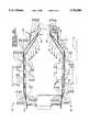
- FIG. 2is an enlarged sectional side view of a combustion liner embodying the present invention
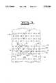
- FIG. 3is an enlarged sectional view taken along line 3 of FIG. 2;
- FIG. 4is an enlarged sectional view taken along line 4 of FIG. 2.
- the gas turbine engine 10includes an air flow delivery system 12 for providing combustion air and for providing cooling air for cooling components of the engine 10.
- the engine 10includes a turbine section 14, a combustor section 16 and a compressor section 18.
- the combustor section 16 and the compressor section 18are operatively connected to the turbine section 14.
- the combustor section 16includes an annular combustion chamber 24 being positioned about a central axis 26 of the gas turbine engine 10.
- thiscould include a plurality of can combustors without changing the essence of the invention.
- the annular combustion chamber 24is operative positioned between the compressor section 18 and the turbine section 14.
- a plurality of fuel nozzles 34are positioned in an inlet end portion 36 of the annular combustion chamber 24.
- the turbine section 14includes a first stage turbine 38 being centered about the central axis 26.
- the annular combustion chamber 24is enclosed by an inner liner portion 40 and an outer liner portion 42 being spaced apart a preestablished distance.
- the inner liner portion 40is spaced from the central axis 26 a preestablished distance and has a generally cylindrical configuration.
- the inner liner portion 40includes an outer thin sheet metal annularly shaped skin member or interior liner 44 and an inner thin sheet metal annularly shaped skin member or exterior liner 46 being generally spaced one from the other a preestablished distance which in this application ranges from about 6 mm to about 15 mm.
- the outer skin members 44has an inlet end portion 48 and an outlet end portion 50 axially spaced one from the other by an axial portion 52.
- the inner skin member 46has an inlet end portion 54 and an outlet end portion 56 axially spaced one from the other by an axial portion 58.
- the inner liner portion 40further includes an inner inlet member 60 positioned at the inlet end portion 48 of the outer liner portion 44 being in communication with the compressor section 18 and being supported within the gas turbine engine 10 in a conventional manner.
- the outer skin member 44defines a combustion side 62 and a cooling side 64 and has a preestablished configuration including a first end 66 being formed at the inlet end portion 48 and being attached to the inlet member 60.
- the inlet end portion 48includes an axial portion 68 being connected to the inlet member 60 and a radial portion 70 extending from the axial portion 68.
- a straight portion 72is connected to the radial portion 70 and forms a portion of the axial portion 52.
- An annular gallery 74is formed between a portion of the straight portion 72, the radial portion 70 and a portion of the inlet member 60.
- a plurality of passages 76extend through the radial portion 70 and communicate a flow of cooling air from the air flow delivery system 12 to the annular gallery 74.
- Spaced along the straight portion 72 at a preestablished distance and attached to the cooling side 64is a plurality of stiffener members 78.
- a plurality of effusion cooling holes 80are positioned in rows 82 along the straight portion 72.
- the rows 82 of the plurality of effusion cooling holes 80are positioned axially along the straight portion 72 being spaced apart at a preestablished distance.
- the cooling holes 80are spaced circumferentially along the rows 82 at preestablished intervals.
- the plurality of effusion cooling holes 80are positioned in the outer skin member 44 at an angle of about 15 to 30 degrees and extend from the cooling side 64 through to the combustion side 62 and angle from the inlet end portion 48 toward the outlet end portion 50.
- a frustoconical or tapered portion 84is connected to the straight portion 72 and forms the outlet end portion 50.
- the frustoconical portion 84defines a cooling side 86 and a combustion side 88.
- Additional ones of the plurality of effusion cooling holes 80are positioned in additional rows 82 along the frustoconical portion 84 and extend between the cooling side 86 and the combustion side 88 at an angle and angle from the inlet end portion 48 toward the outlet end portion 50.
- a transition portion 90is connected to the frustoconical portion 84 and communicates with the turbine section 14. Further positioned in the frustoconical portion 84 is at least a row of dilution holes 92.
- the dilution hole 92extends from the cooling side 86 through to the combustion hot side 88 at about a 90 degree angle.
- the spacing of the rows 82 and the positioning of the plurality of effusing cooling holes 80 along each of the rows 82are arranged in a preestablished pattern 94 being generally defined as a diamond configuration having a centroid 96.
- the inner skin member 46 of the inner liner portion 40defines a first surface 100 being positioned adjacent the cooling side 64,86 and a second surface 102 being opposite the first surface 100.
- the inlet end portion 54 of the inner skin member 46is attached to the straight portion 72 of the outer skin member 44 and has a configuration which spaces the outer and inner skin members 44,46 apart forming a first cooling cavity 106 therebetween.
- a straight portion 108 of the inner skin member 46has a first end 110 and a second end 112.
- the first end 110is connected to the first end portion 54 of the inner skin member 46 and has the first surface 100 spaced from the cooling side 64 a preestablished distance being generally equal along the entire axial distance of the straight portion 108 and forms a portion of the axial portion 52.
- the first cavity 106is generally uniformly spaced apart a preestablished distance along an axial distance of the first cavity 106.
- the axial distance of the first cavity 106being generally equal to the axial distance of the straight portion 108.
- a plurality of impingement holes 114are positioned in a row 116 along the straight portion 108.
- the rows 116 of the plurality of impingement holes 114are positioned axially along the straight portion 108 being spaced apart at a preestablished distance.
- the impingement holes 114are spaced circumferentially along the rows 116 at preestablished intervals.
- the impingement holes 114are positioned at generally a 90 degree angle to the first and second surfaces 100,102 of the inner skin member 46.
- the flow of cooling air from the air flow delivery system 12is communicated to the first cooling cavity 106 through the plurality of impingement cooling holes 114.
- the spacing of the rows 116 and the positioning of the plurality of impingement holes 114 along each of the rows 116are arranged in a preestablished pattern 118 being generally defined as a diamond configuration having a centroid 120.
- the plurality of holes 114 in the straight portion 108 of the inner member 46are positioned in radial alignment with the centroid 96 of the preestablished pattern 94 of the plurality of holes 80 in the outer member 44.
- a plurality of spacer members 122are intermittently positioned between the cooling side 64 of the outer skin member 44 and the first surface 100 of the inner skin member 46.
- Each of the spacer members 122is attached to an annular member 124 in which the second end 112 of the straight portion 108 is positioned therein.
- Connected to the spacer members 122 and the annular sliding member 124is an annular arcuate or tapered portion 126 at a first end 128 and has a second end 130 corresponding to the outlet end portion 56 connected to the transition portion 90.
- the annular arcuate portion 126is spaced from the frustoconical portion 84 and forms a second cooling cavity 140.
- the spacing of the annular arcuate portion 126 from the frustoconical portion 84is not necessarily evenly spaced along the second cooling cavity 140 between the first end 128 and the second end 130 of the annular arcuate portion 126.
- the spaced apart distance of the second cavity 140is of a non-uniform spacing and the distance is smaller adjacent the second end 130.
- a plurality of non metering airflow inlet holes 142are positioned in rows 144 and along the circumference of the rows 144 at predetermined locations. The plurality of non metering airflow inlet holes 142 are located closer to the first end 128 than to the second end 130 of the frustoconical portion 84.
- the flew of cooling air from the air flow delivery system 12is communicated to the second cooling cavity 140 through the plurality of non metering airflow inlet holes 142. But, cooling airflow from the flow delivery system 12 is delivered to the first cooling cavity 106 and to the areas between the plurality of spacer members 122 by the impingement cooling holes 114.
- a support member 146is attached to the annular arcuate portion 126 and supports the outlet end portion 50 of the outer skin member 44 by way of the transition portion 90 and the outlet end portion 56 of the inner skin member 46 in a conventional manner.
- the outer liner portion 42is spaced from the central axis 26 a preestablished distance, which in this application is a greater distance than the preestablished distance from the central axis 26 than that of the inner liner portion 40, and has a generally cylindrical configuration.
- the outer liner portion 42includes an inner thin sheet metal annularly shaped skin member or interior liner 150 and an outer thin sheet metal annularly shaped skin member or exterior liner 152 being generally spaced one from the other a preestablished distance which in this application ranges from about 6 mm and about 15 mm.
- the inner skin member 150has an inlet end portion 154 and an outlet end portion 156 axially spaced one from the other by an axial portion 158.
- the outer skin member 152has an inlet end portion 160 and an outlet end portion 162 axially spaced one from the other by an axial portion 164.
- the outer liner portion 42further includes an outer inlet member 166 positioned at the inlet end portion 154 of the inner skin member 150 being in communication with the compressor section 18 and being supported within the gas turbine engine 10 in a conventional manner.
- the inner skin member 150defines a combustion side 168 and a cooling side 170 and has a preestablished configuration including a first end 172 being formed at the inlet end portion 154 and being attached to the outer inlet member 166.
- the inlet end portion 154includes an axial portion 174 being connected to the outer inlet member 166 and a radial portion 176 extending from the axial portion 174.
- a straight portion 178is connected to the radial portion 176 and forms a portion of the axial portion 158.
- An annular gallery 180is formed between a portion of the straight portion 178, the radial portion 176 and a portion of the outer inlet member 166.
- a plurality of passages 182extend through the radial portion 176 and communicate a flow of cooling air from the air flow delivery system 12 to the annular gallery 180.
- Spaced along the straight portion 178 at a preestablished distance and attached to the cooling side 170is a plurality of stiffener members 184.
- a plurality of effusion cooling holes 186are positioned in rows 188 along the straight portion 178. The rows 188 of the plurality of effusion cooling holes 186 are positioned axially along the straight portion 178 being spaced apart at a preestablished distance.
- the cooling holes 186are spaced circumferentially along the rows 188 at preestablished intervals.
- the plurality of effusion cooling holes 186are positioned in the inner skin member 150 at an angle of about 15 to 20 degrees and extend from the cooling side 170 through to the combustion side 168 and angle from the inlet end portion 154 toward the outlet end portion 156.
- An inner conical or tapered portion 190is connected to the straight portion 178 and forms the outlet end portion 156.
- the inner conical portion 190defines a cooling side 192 and a combustion side 194.
- Additional ones of the plurality of effusion cooling holes 186are positioned in additional rows 188 along the inner conical portion 190 and extend between the cooling side 192 and the combustion side 194 at an angle and angle from the inlet end portion 154 toward the outlet end portion 156.
- a transition portion 196is connected to the inner conical portion 190 and communicates with the turbine section 14.
- Further positioned in the inner conical portion 190is at least a row of dilution holes 198.
- the dilution hole 198extend from the cooling side 192 through to the combustion side 194 at about a 90 degree.
- the spacing of the rows 188 and the positioning of the plurality of effusing cooling holes 186 along each of the rows 188are arranged in a preestablished pattern 200 being generally defined as a diamond configuration having a centroid 202.
- the outer skin member 152 of the outer liner portion 42defines a first surface 210 being positioned adjacent the cooling side 170 and a second surface 212 being opposite the first surface 210.
- the inlet end portion 160 of the outer skin member 152is attached to the straight portion 178 of the inner skin member 150 and has a configuration which spaces the inner and outer skin members 150,152 apart forming a first cooling cavity 216 therebetween.
- a straight portion 218 of the outer skin member 152has a first end 220 and a second end 222.
- the first end 220is connected to the inlet end portion 160 of the inner skin member 150 and has the first surface 210 spaced from the cooling side 192 a preestablished distance being generally equal along the entire axial distance of the straight portion 218 and forms a portion of the axial portion 164.
- the first cavity 216being generally uniformly spaced apart a preestablished distance along an axial distance of the first cavity 216.
- the axial distance of the first cavity 216being generally equal to the axial distance of the straight portion 218.
- a plurality of impingement holes 224are positioned in a row 226 along the straight portion 218.
- the rows 226 of the plurality of impingement holes 224are positioned axially along the straight portion 218 being spaced apart at a preestablished distance.
- the impingement holes 224are spaced circumferentially along the rows 226 at preestablished intervals.
- the impingement holes 224are positioned at generally a 90 degree angle to the first and second surfaces 210,212 of the outer skin member 152.
- the flow of cooling air from the air flow delivery system 12is communicated to the first cooling cavity 216 through the plurality of impingement cooling holes 224.
- the spacing of the rows 226 and the positioning of the plurality of impingement holes 224 along each of the rows 226are arranged in a preestablished pattern 228 being generally defined as a diamond configuration having a centroid 230.
- the plurality of holes 224 in straight portion 218 of the outer member 152are positioned in radial alignment with the centroid 202 of the preestablished pattern 200 of the plurality of holes 186 in the inner member 150.
- a plurality of spacer members 232are intermittently positioned between the cooling side 170 of the inner skin member 150 and the first surface 210 of the outer skin member 152.
- Each of the spacer members 232are attached to an annular sliding member 234 in which the second end 222 of the straight portion 218 is slidably positioned.
- an outer conical or tapered portion 236Connected to the spacer members 232 and the annular sliding member 234 is an outer conical or tapered portion 236 at a first end 238 and has a second end 240 corresponding to the outlet end portion 162 connected to the transition portion 196.
- the outer conical portion 236is spaced from the inner conical portion 190 and forms a second cooling cavity 250.
- the spacing of the outer conical portion 236 from the inner conical portion 190 in this applicationis not necessarily evenly spaced along the second cooling cavity 250 between the first end 238 and the second end 240 of the outer conical portion 236.
- the spaced apart distance of the second cavity 250is of a non-uniform spacing and the distance is smaller adjacent the second end 240.
- a plurality of non metering access holes 252are positioned in rows 254 and along the circumference of the rows 254 at predetermined locations.
- the plurality of non metering access holes 252are located closer to the first end 238 than to the second end 240 of the outer conical portion 236.
- the flow of cooling air from the air delivery system 12is communicated to the second cooling cavity 250 through the plurality of non metering access holes 252.
- cooling airflow from the flow delivery system 12is delivered to the first cooling cavity 216 and to the area between the plurality of spacer members 232 by the impingement cooling holes 224.
- a support member 256is attached to the outer conical portion 236 and supports the outlet end portion 156 of the inner skin member 150 by way of the transition portion 196 and the outlet end portion 162 of the outer skin member 152 in a conventional manner.
- the primary advantages of the improved combustor liner portions 24is in the efficient use of the compressed cooling air. Since less cooling airflow per unit length of combustor wall, inner liner portion 40 and outer liner portion 42, is used there is a substantial reduction of CO emissions.
- the inner skin members 46 and outer skin member 152 of the inner liner and outer liner portions 40,42respectively have a lower heat rejection to the gas turbine engine 10.
- the combination of the impingement and effusion cooling and the location of the plurality of impingement cooling holes 114,224 relative to the plurality of effusion cooling holes 80,186allows the combustion chamber 24 to be subject to a very high heat flux as a result of high heat transfer rates conveyed by radiation and convection arising from the burning of fuel to be consistent with the design life expectancy of the combustor and its material properties.
- the improved impingement and effusion cooled combustorincreases efficiency, reduces emissions and increases or maintains component life.
Landscapes
- Engineering & Computer Science (AREA)
- Chemical & Material Sciences (AREA)
- Combustion & Propulsion (AREA)
- Mechanical Engineering (AREA)
- General Engineering & Computer Science (AREA)
- Turbine Rotor Nozzle Sealing (AREA)
Abstract
Description
This invention relates generally to a gas turbine engine and more particularly to an improved low emission combustor for use with the gas turbine engine.
1. Background Art
High performance gas turbine engines require increased firing temperatures and increased compressor pressures. Coolant from the compressor section is directed through cooling passages in various components to enhance reliability and cycle life of individual components within the engine. For example, to improve fuel economy characteristics, engines are being operated at higher temperatures than the material physical property limits of which the engine components are constructed. These higher temperatures, if not compensated for, oxidize engine components, distort engine components and decrease component life. Cooling passages are used to direct a flow of air to such engine components to reduce the high temperature of the components and prolong component life by limiting the temperature to a level which is consistent with material properties of such components.
However, as the amount of coolant air is increased to cool the engine components the amount of air available for the combustion chamber is decreased. Thus, systems and methods of increasing cooling efficiency and reducing the amount of coolant used to cool the engine components must be utilized.
The present invention is directed to overcome one or more of the problems as set forth above.
2. Disclosure of the Invention
In one aspect of the present invention, a combustor is comprised of an interior liner defining an inlet end portion and an outlet end portion being spaced apart by an axial portion. The interior liner defines a combustion side and a cooling side having a plurality of effusion holes defined therein extending between the combustion side and the cooling side. The plurality of effusion holes are formed in a preestablished pattern defining a centroid. The combustor further includes an exterior liner defining an inlet end portion and an outlet end portion being spaced apart by an axial portion. The exterior liner defines a first surface and a second surface having a plurality of impingement holes defined therein extending between the first surface and the second surface at an angle of about 90 degrees. The plurality of impingement holes are formed in a preestablished pattern and at least a portion of the plurality of impingement holes in the exterior liner are positioned in radial alignment with the centroid of the preestablished pattern of the plurality of effusion holes in the interior liner.
FIG. 1 is a partially sectioned partial view of a gas turbine engine embodying the present invention;
FIG. 2 is an enlarged sectional side view of a combustion liner embodying the present invention;
FIG. 3 is an enlarged sectional view taken alongline 3 of FIG. 2; and
FIG. 4 is an enlarged sectional view taken alongline 4 of FIG. 2.
Referring to FIG. 1, agas turbine engine 10 is shown but not in its entirety. Thegas turbine engine 10 includes an airflow delivery system 12 for providing combustion air and for providing cooling air for cooling components of theengine 10. Theengine 10 includes aturbine section 14, acombustor section 16 and acompressor section 18. Thecombustor section 16 and thecompressor section 18 are operatively connected to theturbine section 14. In this application thecombustor section 16 includes anannular combustion chamber 24 being positioned about acentral axis 26 of thegas turbine engine 10. As an alternative this could include a plurality of can combustors without changing the essence of the invention. Theannular combustion chamber 24 is operative positioned between thecompressor section 18 and theturbine section 14. A plurality of fuel nozzles 34 (one shown) are positioned in aninlet end portion 36 of theannular combustion chamber 24. Theturbine section 14 includes afirst stage turbine 38 being centered about thecentral axis 26.
As best shown in FIG. 2, theannular combustion chamber 24 is enclosed by aninner liner portion 40 and anouter liner portion 42 being spaced apart a preestablished distance. Theinner liner portion 40 is spaced from the central axis 26 a preestablished distance and has a generally cylindrical configuration. Theinner liner portion 40 includes an outer thin sheet metal annularly shaped skin member orinterior liner 44 and an inner thin sheet metal annularly shaped skin member orexterior liner 46 being generally spaced one from the other a preestablished distance which in this application ranges from about 6 mm to about 15 mm. Theouter skin members 44 has aninlet end portion 48 and anoutlet end portion 50 axially spaced one from the other by anaxial portion 52. And, theinner skin member 46 has aninlet end portion 54 and anoutlet end portion 56 axially spaced one from the other by anaxial portion 58.
As further shown in FIG. 2, theinner liner portion 40 further includes aninner inlet member 60 positioned at theinlet end portion 48 of theouter liner portion 44 being in communication with thecompressor section 18 and being supported within thegas turbine engine 10 in a conventional manner. Theouter skin member 44 defines acombustion side 62 and acooling side 64 and has a preestablished configuration including afirst end 66 being formed at theinlet end portion 48 and being attached to theinlet member 60. Theinlet end portion 48 includes anaxial portion 68 being connected to theinlet member 60 and aradial portion 70 extending from theaxial portion 68. Astraight portion 72 is connected to theradial portion 70 and forms a portion of theaxial portion 52. Anannular gallery 74 is formed between a portion of thestraight portion 72, theradial portion 70 and a portion of theinlet member 60. A plurality ofpassages 76 extend through theradial portion 70 and communicate a flow of cooling air from the airflow delivery system 12 to theannular gallery 74. Spaced along thestraight portion 72 at a preestablished distance and attached to thecooling side 64 is a plurality ofstiffener members 78. A plurality ofeffusion cooling holes 80 are positioned inrows 82 along thestraight portion 72. Therows 82 of the plurality ofeffusion cooling holes 80 are positioned axially along thestraight portion 72 being spaced apart at a preestablished distance. Thecooling holes 80 are spaced circumferentially along therows 82 at preestablished intervals. The plurality ofeffusion cooling holes 80 are positioned in theouter skin member 44 at an angle of about 15 to 30 degrees and extend from thecooling side 64 through to thecombustion side 62 and angle from theinlet end portion 48 toward theoutlet end portion 50. A frustoconical ortapered portion 84 is connected to thestraight portion 72 and forms theoutlet end portion 50. Thefrustoconical portion 84 defines acooling side 86 and acombustion side 88. Additional ones of the plurality ofeffusion cooling holes 80 are positioned inadditional rows 82 along thefrustoconical portion 84 and extend between thecooling side 86 and thecombustion side 88 at an angle and angle from theinlet end portion 48 toward theoutlet end portion 50. Atransition portion 90 is connected to thefrustoconical portion 84 and communicates with theturbine section 14. Further positioned in thefrustoconical portion 84 is at least a row ofdilution holes 92. Thedilution hole 92 extends from thecooling side 86 through to the combustionhot side 88 at about a 90 degree angle. As best shown in FIG. 3, the spacing of therows 82 and the positioning of the plurality of effusingcooling holes 80 along each of therows 82 are arranged in apreestablished pattern 94 being generally defined as a diamond configuration having a centroid 96.
As further shown in FIG. 2, theinner skin member 46 of theinner liner portion 40 defines afirst surface 100 being positioned adjacent thecooling side second surface 102 being opposite thefirst surface 100. Theinlet end portion 54 of theinner skin member 46 is attached to thestraight portion 72 of theouter skin member 44 and has a configuration which spaces the outer andinner skin members first cooling cavity 106 therebetween. Astraight portion 108 of theinner skin member 46 has afirst end 110 and asecond end 112. Thefirst end 110 is connected to thefirst end portion 54 of theinner skin member 46 and has thefirst surface 100 spaced from the cooling side 64 a preestablished distance being generally equal along the entire axial distance of thestraight portion 108 and forms a portion of theaxial portion 52. Thefirst cavity 106 is generally uniformly spaced apart a preestablished distance along an axial distance of thefirst cavity 106. The axial distance of thefirst cavity 106 being generally equal to the axial distance of thestraight portion 108. A plurality ofimpingement holes 114 are positioned in arow 116 along thestraight portion 108. Therows 116 of the plurality of impingement holes 114 are positioned axially along thestraight portion 108 being spaced apart at a preestablished distance. The impingement holes 114 are spaced circumferentially along therows 116 at preestablished intervals. The impingement holes 114 are positioned at generally a 90 degree angle to the first and second surfaces 100,102 of theinner skin member 46. The flow of cooling air from the airflow delivery system 12 is communicated to thefirst cooling cavity 106 through the plurality of impingement cooling holes 114. As best shown in FIG. 3, the spacing of therows 116 and the positioning of the plurality of impingement holes 114 along each of therows 116 are arranged in apreestablished pattern 118 being generally defined as a diamond configuration having acentroid 120. The plurality ofholes 114 in thestraight portion 108 of theinner member 46 are positioned in radial alignment with thecentroid 96 of thepreestablished pattern 94 of the plurality ofholes 80 in theouter member 44. At thesecond end 112 of thestraight portion 108, a plurality ofspacer members 122 are intermittently positioned between the coolingside 64 of theouter skin member 44 and thefirst surface 100 of theinner skin member 46. Each of thespacer members 122 is attached to anannular member 124 in which thesecond end 112 of thestraight portion 108 is positioned therein. Connected to thespacer members 122 and the annular slidingmember 124 is an annular arcuate or taperedportion 126 at afirst end 128 and has asecond end 130 corresponding to theoutlet end portion 56 connected to thetransition portion 90. The annulararcuate portion 126 is spaced from thefrustoconical portion 84 and forms asecond cooling cavity 140. The spacing of the annulararcuate portion 126 from thefrustoconical portion 84, in this application, is not necessarily evenly spaced along thesecond cooling cavity 140 between thefirst end 128 and thesecond end 130 of the annulararcuate portion 126. In this application, the spaced apart distance of thesecond cavity 140 is of a non-uniform spacing and the distance is smaller adjacent thesecond end 130. A plurality of non metering airflow inlet holes 142 are positioned inrows 144 and along the circumference of therows 144 at predetermined locations. The plurality of non metering airflow inlet holes 142 are located closer to thefirst end 128 than to thesecond end 130 of thefrustoconical portion 84. The flew of cooling air from the airflow delivery system 12 is communicated to thesecond cooling cavity 140 through the plurality of non metering airflow inlet holes 142. But, cooling airflow from theflow delivery system 12 is delivered to thefirst cooling cavity 106 and to the areas between the plurality ofspacer members 122 by the impingement cooling holes 114. Asupport member 146 is attached to the annulararcuate portion 126 and supports theoutlet end portion 50 of theouter skin member 44 by way of thetransition portion 90 and theoutlet end portion 56 of theinner skin member 46 in a conventional manner.
Theouter liner portion 42 is spaced from the central axis 26 a preestablished distance, which in this application is a greater distance than the preestablished distance from thecentral axis 26 than that of theinner liner portion 40, and has a generally cylindrical configuration. Theouter liner portion 42 includes an inner thin sheet metal annularly shaped skin member orinterior liner 150 and an outer thin sheet metal annularly shaped skin member orexterior liner 152 being generally spaced one from the other a preestablished distance which in this application ranges from about 6 mm and about 15 mm. Theinner skin member 150 has aninlet end portion 154 and anoutlet end portion 156 axially spaced one from the other by anaxial portion 158. And, theouter skin member 152 has aninlet end portion 160 and an outlet end portion 162 axially spaced one from the other by anaxial portion 164.
Theouter liner portion 42 further includes anouter inlet member 166 positioned at theinlet end portion 154 of theinner skin member 150 being in communication with thecompressor section 18 and being supported within thegas turbine engine 10 in a conventional manner. Theinner skin member 150 defines acombustion side 168 and acooling side 170 and has a preestablished configuration including afirst end 172 being formed at theinlet end portion 154 and being attached to theouter inlet member 166. Theinlet end portion 154 includes anaxial portion 174 being connected to theouter inlet member 166 and aradial portion 176 extending from theaxial portion 174. Astraight portion 178 is connected to theradial portion 176 and forms a portion of theaxial portion 158. Anannular gallery 180 is formed between a portion of thestraight portion 178, theradial portion 176 and a portion of theouter inlet member 166. A plurality ofpassages 182 extend through theradial portion 176 and communicate a flow of cooling air from the airflow delivery system 12 to theannular gallery 180. Spaced along thestraight portion 178 at a preestablished distance and attached to thecooling side 170 is a plurality ofstiffener members 184. A plurality of effusion cooling holes 186 are positioned inrows 188 along thestraight portion 178. Therows 188 of the plurality of effusion cooling holes 186 are positioned axially along thestraight portion 178 being spaced apart at a preestablished distance. The cooling holes 186 are spaced circumferentially along therows 188 at preestablished intervals. The plurality of effusion cooling holes 186 are positioned in theinner skin member 150 at an angle of about 15 to 20 degrees and extend from thecooling side 170 through to thecombustion side 168 and angle from theinlet end portion 154 toward theoutlet end portion 156. An inner conical or taperedportion 190 is connected to thestraight portion 178 and forms theoutlet end portion 156. The innerconical portion 190 defines acooling side 192 and acombustion side 194. Additional ones of the plurality of effusion cooling holes 186 are positioned inadditional rows 188 along the innerconical portion 190 and extend between the coolingside 192 and thecombustion side 194 at an angle and angle from theinlet end portion 154 toward theoutlet end portion 156. Atransition portion 196 is connected to the innerconical portion 190 and communicates with theturbine section 14. Further positioned in the innerconical portion 190 is at least a row of dilution holes 198. Thedilution hole 198 extend from thecooling side 192 through to thecombustion side 194 at about a 90 degree. As best shown in FIG. 4, the spacing of therows 188 and the positioning of the plurality of effusingcooling holes 186 along each of therows 188 are arranged in apreestablished pattern 200 being generally defined as a diamond configuration having acentroid 202.
Theouter skin member 152 of theouter liner portion 42 defines afirst surface 210 being positioned adjacent thecooling side 170 and asecond surface 212 being opposite thefirst surface 210. Theinlet end portion 160 of theouter skin member 152 is attached to thestraight portion 178 of theinner skin member 150 and has a configuration which spaces the inner and outer skin members 150,152 apart forming afirst cooling cavity 216 therebetween. Astraight portion 218 of theouter skin member 152 has afirst end 220 and asecond end 222. Thefirst end 220 is connected to theinlet end portion 160 of theinner skin member 150 and has thefirst surface 210 spaced from the cooling side 192 a preestablished distance being generally equal along the entire axial distance of thestraight portion 218 and forms a portion of theaxial portion 164. Thefirst cavity 216 being generally uniformly spaced apart a preestablished distance along an axial distance of thefirst cavity 216. The axial distance of thefirst cavity 216 being generally equal to the axial distance of thestraight portion 218. A plurality of impingement holes 224 are positioned in arow 226 along thestraight portion 218. Therows 226 of the plurality of impingement holes 224 are positioned axially along thestraight portion 218 being spaced apart at a preestablished distance. The impingement holes 224 are spaced circumferentially along therows 226 at preestablished intervals. The impingement holes 224 are positioned at generally a 90 degree angle to the first and second surfaces 210,212 of theouter skin member 152. The flow of cooling air from the airflow delivery system 12 is communicated to thefirst cooling cavity 216 through the plurality of impingement cooling holes 224. As best shown in FIG. 4, the spacing of therows 226 and the positioning of the plurality of impingement holes 224 along each of therows 226 are arranged in apreestablished pattern 228 being generally defined as a diamond configuration having acentroid 230. The plurality ofholes 224 instraight portion 218 of theouter member 152 are positioned in radial alignment with thecentroid 202 of thepreestablished pattern 200 of the plurality ofholes 186 in theinner member 150. At thesecond end 222 of thestraight portion 218, a plurality ofspacer members 232 are intermittently positioned between the coolingside 170 of theinner skin member 150 and thefirst surface 210 of theouter skin member 152. Each of thespacer members 232 are attached to an annular slidingmember 234 in which thesecond end 222 of thestraight portion 218 is slidably positioned. Connected to thespacer members 232 and the annular slidingmember 234 is an outer conical or taperedportion 236 at afirst end 238 and has asecond end 240 corresponding to the outlet end portion 162 connected to thetransition portion 196. The outerconical portion 236 is spaced from the innerconical portion 190 and forms asecond cooling cavity 250. The spacing of the outerconical portion 236 from the innerconical portion 190 in this application is not necessarily evenly spaced along thesecond cooling cavity 250 between thefirst end 238 and thesecond end 240 of the outerconical portion 236. In this application, the spaced apart distance of thesecond cavity 250 is of a non-uniform spacing and the distance is smaller adjacent thesecond end 240. A plurality of non metering access holes 252 are positioned inrows 254 and along the circumference of therows 254 at predetermined locations. The plurality of non metering access holes 252 are located closer to thefirst end 238 than to thesecond end 240 of the outerconical portion 236. The flow of cooling air from theair delivery system 12 is communicated to thesecond cooling cavity 250 through the plurality of non metering access holes 252. But, cooling airflow from theflow delivery system 12 is delivered to thefirst cooling cavity 216 and to the area between the plurality ofspacer members 232 by the impingement cooling holes 224. Asupport member 256 is attached to the outerconical portion 236 and supports theoutlet end portion 156 of theinner skin member 150 by way of thetransition portion 196 and the outlet end portion 162 of theouter skin member 152 in a conventional manner.
Thus, the primary advantages of the improvedcombustor liner portions 24 is in the efficient use of the compressed cooling air. Since less cooling airflow per unit length of combustor wall,inner liner portion 40 andouter liner portion 42, is used there is a substantial reduction of CO emissions. Theinner skin members 46 andouter skin member 152 of the inner liner andouter liner portions gas turbine engine 10. The combination of the impingement and effusion cooling and the location of the plurality of impingement cooling holes 114,224 relative to the plurality of effusion cooling holes 80,186 allows thecombustion chamber 24 to be subject to a very high heat flux as a result of high heat transfer rates conveyed by radiation and convection arising from the burning of fuel to be consistent with the design life expectancy of the combustor and its material properties. Thus, the improved impingement and effusion cooled combustor increases efficiency, reduces emissions and increases or maintains component life.
Other aspects, objects and advantages of this invention can be obtained from a study of the drawings, the disclosure and the appended claims.
Claims (23)
1. A combustor comprising:
an interior liner defining an inlet end portion and an outlet end portion being spaced apart by an axial portion, said interior liner defining a combustion side and a cooling side having a plurality of effusion holes defined therein extending between the combustion side and the cooling side, said plurality of effusion holes being formed in a preestablished pattern defining a centroid;
an exterior liner defining an inlet end portion and an outlet end portion being spaced apart by an axial portion, said exterior liner defining a first surface and a second surface having a plurality of impingement holes defined therein extending between the first surface and the second surface at an angle of about 90 degrees, said plurality of impingement holes being formed in a preestablished pattern;
said interior liner being spaced from said exterior liner forming a gallery therebetween, said gallery extending continually along said axial portion of said interior liner and said exterior liner; and
at least a portion of said plurality of impingement holes in the exterior liner being positioned in radial alignment with the centroid of the preestablished pattern of the plurality of effusion holes in the interior liner.
2. The combustor of claim 1 wherein said portion of said plurality of impingement holes in the exterior liner are positioned in the axial portion.
3. The combustor of claim 1 wherein said plurality of effusion holes in the interior liner are at an angle between the combustion side and the cooling side.
4. The combustor of claim 3 wherein said angle extends from the inlet end portion toward the outlet end portion.
5. The combustor of claim 1 further including an inlet member being attached to the interior liner and forming a gallery therebetween.
6. The combustor of claim 5 wherein said interior liner has a plurality of passages therein being in communication with the gallery.
7. The combustor of claim 1 wherein said interior liner and said exterior liner has a cavity formed therebetween being in communication with the plurality of effusion holes in the interior liner and the plurality of impingement holes in the exterior liner.
8. The combustor of claim 1 wherein said interior liner and said exterior liner have a spacer member positioned therebetween defining a preestablished spacing therebetween forming a cavity therebetween.
9. The combustor of claim 1 wherein said interior liner and said exterior liner have a plurality of stiffening members positioned therebetween.
10. The combustor of claim 1 further including a transition portion connected to the outlet end portion and said exterior liner includes a straight portion defining a first end being attached to the inlet end portion and a second end, and a tapered portion having a first end and a second end connected to the transition portion, said second end of the straight portion and said first end of said tapered portion being slidably connected.
11. The combustor of claim 10 wherein said tapered portion has a dilution hole located therein.
12. The combustor of claim 11 wherein only said straight portion has the plurality of impingement holes therein.
13. The combustor of claim 1 further including a plurality of stiffener members attached to the interior liner.
14. The combustor of claim 13 wherein said plurality of stiffener members are attached to the cooling side of the interior liner.
15. The combustor of claim 1 wherein said axial portion of the interior liner includes a straight portion and a tapered portion and said plurality of effusion holes are located in the straight portion and the tapered portion.
16. The combustor of claim 15 wherein said axial portion of the exterior liner includes a straight portion and a tapered portion and said plurality of impingement holes are located in only the straight portion.
17. The combustor of claim 15 wherein said axial portion of the exterior liner includes a straight portion and a tapered portion and said plurality of impingement holes are located in each of the straight portion and the tapered portion.
18. The combustor of claim 16 wherein said tapered portion of the exterior liner has a plurality of non metering access holes defined therein.
19. The combustor of claim 18 wherein said tapered portion of the exterior liner includes a first end being adjacent the straight portion and a second end being adjacent the outlet end portion said plurality of non metering access holes being spaced more closely to the first end.
20. The combustor of claim 1 wherein said axial portion of the interior liner includes a straight portion being adjacent the inlet end portion and a tapered portion being adjacent the outlet end portion, said axial portion of the exterior liner includes a straight portion being adjacent the inlet end portion and a tapered portion being adjacent the outlet end portion, said straight portion of the interior liner and said straight portion of the exterior liner being spaced apart a preestablished distance forming a first cavity being generally uniform spaced apart distance along an axial distance of the first cavity.
21. The combustor of claim 20 wherein said tapered portion of the interior liner and said tapered portion of the exterior liner being spaced apart a preestablished distance forming a second cavity being of a non-uniform spaced apart distance along an axial distance of the second cavity.
22. The combustor of claim 21 wherein said non-uniform spaced apart distance is smaller adjacent the outlet end portion.
23. A combustor comprising:
an interior liner defining an inlet end portion and an outlet end portion being spaced apart by an axial portion, said interior liner defining a combustion side and a cooling side having a plurality of effusion holes defined therein extending between the combustion side and the cooling side, said plurality of effusion holes being formed in a preestablished pattern defining a centroid;
an exterior liner defining an inlet end portion and an outlet end portion being spaced apart by an axial portion, said exterior liner defining a first surface and a second surface having a pluraity of impingement holes defined therein extending between the first surface and the second surface at an angle of about 90 degrees, said plurality of impingement holes being formed in a preestablished pattern;
at least a portion of said plurality of impingement holes in the exterior liner being positioned in radial alignment with the centroid of the preestablished pattern of the plurality of effusion holes in the interior liner; and
an inlet member being attached to the interior liner and forming a gallery therebetween.
Priority Applications (4)
| Application Number | Priority Date | Filing Date | Title |
|---|---|---|---|
| US08/692,142US5758504A (en) | 1996-08-05 | 1996-08-05 | Impingement/effusion cooled combustor liner |
| CA002208798ACA2208798A1 (en) | 1996-08-05 | 1997-06-24 | Impingement/effusion cooled combustor liner |
| DE19733868ADE19733868A1 (en) | 1996-08-05 | 1997-08-05 | Heavy duty gas turbine burner |
| JP9210468AJPH1068523A (en) | 1996-08-05 | 1997-08-05 | Liner for collision/release cooling combustion device |
Applications Claiming Priority (1)
| Application Number | Priority Date | Filing Date | Title |
|---|---|---|---|
| US08/692,142US5758504A (en) | 1996-08-05 | 1996-08-05 | Impingement/effusion cooled combustor liner |
Publications (1)
| Publication Number | Publication Date |
|---|---|
| US5758504Atrue US5758504A (en) | 1998-06-02 |
Family
ID=24779424
Family Applications (1)
| Application Number | Title | Priority Date | Filing Date |
|---|---|---|---|
| US08/692,142Expired - LifetimeUS5758504A (en) | 1996-08-05 | 1996-08-05 | Impingement/effusion cooled combustor liner |
Country Status (4)
| Country | Link |
|---|---|
| US (1) | US5758504A (en) |
| JP (1) | JPH1068523A (en) |
| CA (1) | CA2208798A1 (en) |
| DE (1) | DE19733868A1 (en) |
Cited By (57)
| Publication number | Priority date | Publication date | Assignee | Title |
|---|---|---|---|---|
| US6079199A (en)* | 1998-06-03 | 2000-06-27 | Pratt & Whitney Canada Inc. | Double pass air impingement and air film cooling for gas turbine combustor walls |
| US6098397A (en)* | 1998-06-08 | 2000-08-08 | Caterpillar Inc. | Combustor for a low-emissions gas turbine engine |
| US6105371A (en)* | 1997-01-16 | 2000-08-22 | Societe Nationale D'etude Et De Construction De Moteurs D'aviation "Snecma" | Control of cooling flows for high-temperature combustion chambers having increased permeability in the downstream direction |
| GB2356924A (en)* | 1999-12-01 | 2001-06-06 | Abb Alstom Power Uk Ltd | Cooling wall structure for combustor |
| US6269628B1 (en)* | 1999-06-10 | 2001-08-07 | Pratt & Whitney Canada Corp. | Apparatus for reducing combustor exit duct cooling |
| WO2002048527A1 (en) | 2000-12-11 | 2002-06-20 | Pratt & Whitney Canada Corp. | Combustor turbine successive dual cooling |
| US6494044B1 (en)* | 1999-11-19 | 2002-12-17 | General Electric Company | Aerodynamic devices for enhancing sidepanel cooling on an impingement cooled transition duct and related method |
| US6568187B1 (en) | 2001-12-10 | 2003-05-27 | Power Systems Mfg, Llc | Effusion cooled transition duct |
| US6609362B2 (en) | 2001-07-13 | 2003-08-26 | Pratt & Whitney Canada Corp. | Apparatus for adjusting combustor cycle |
| US6640547B2 (en)* | 2001-12-10 | 2003-11-04 | Power Systems Mfg, Llc | Effusion cooled transition duct with shaped cooling holes |
| US20040011021A1 (en)* | 2001-08-28 | 2004-01-22 | Honda Giken Kogyo Kabushiki Kaisha | Gas-turbine engine combustor |
| US20040123598A1 (en)* | 2002-12-31 | 2004-07-01 | General Electric Company | High temperature combustor wall for temperature reduction by optical reflection and process for manufacturing |
| WO2004097300A1 (en)* | 2003-04-28 | 2004-11-11 | Pratt & Whitney Canada Corp. | Noise reducing combustor |
| US20040248053A1 (en)* | 2001-09-07 | 2004-12-09 | Urs Benz | Damping arrangement for reducing combustion-chamber pulsation in a gas turbine system |
| EP1171705A4 (en)* | 1999-03-10 | 2005-01-12 | Williams Int Co Llc | Rocket engine |
| US20050056020A1 (en)* | 2003-08-26 | 2005-03-17 | Honeywell International Inc. | Tube cooled combustor |
| US6868675B1 (en) | 2004-01-09 | 2005-03-22 | Honeywell International Inc. | Apparatus and method for controlling combustor liner carbon formation |
| US20050097890A1 (en)* | 2003-08-29 | 2005-05-12 | Mitsubishi Heavy Industries, Ltd. | Gas turbine combustor |
| US6907736B2 (en)* | 2001-01-09 | 2005-06-21 | Mitsubishi Heavy Industries, Ltd. | Gas turbine combustor having an acoustic energy absorbing wall |
| US20050229606A1 (en)* | 2004-04-15 | 2005-10-20 | Snecma Moteurs | Annular combustion chamber for a turbomachine with an improved inner fastening flange |
| US20050268613A1 (en)* | 2004-06-01 | 2005-12-08 | General Electric Company | Method and apparatus for cooling combustor liner and transition piece of a gas turbine |
| EP1650503A1 (en)* | 2004-10-25 | 2006-04-26 | Siemens Aktiengesellschaft | Method for cooling a heat shield element and a heat shield element |
| US20060137324A1 (en)* | 2004-12-29 | 2006-06-29 | United Technologies Corporation | Inner plenum dual wall liner |
| US20070062198A1 (en)* | 2003-05-30 | 2007-03-22 | Siemens Aktiengesellschaft | Combustion chamber |
| US20070271926A1 (en)* | 2006-05-26 | 2007-11-29 | Pratt & Whitney Canada Corp. | Noise reducing combustor |
| EP1905997A1 (en)* | 1999-03-10 | 2008-04-02 | Williams International Co., L.L.C. | Rocket enginge |
| US20080271376A1 (en)* | 2007-05-01 | 2008-11-06 | General Electric Company | Fuel reformer system and a method for operating the same |
| US7628020B2 (en) | 2006-05-26 | 2009-12-08 | Pratt & Whitney Canada Cororation | Combustor with improved swirl |
| DE102008026463A1 (en)* | 2008-06-03 | 2009-12-10 | E.On Ruhrgas Ag | Combustion device for gas turbine system in natural gas pipeline network, has cooling arrays arranged over circumference of central body, distributed at preset position on body, and provided adjacent to primary fuel injectors |
| US20100050650A1 (en)* | 2008-08-29 | 2010-03-04 | Patel Bhawan B | Gas turbine engine reverse-flow combustor |
| US20100064693A1 (en)* | 2008-09-15 | 2010-03-18 | Koenig Michael H | Combustor assembly comprising a combustor device, a transition duct and a flow conditioner |
| US20100071379A1 (en)* | 2008-09-25 | 2010-03-25 | Honeywell International Inc. | Effusion cooling techniques for combustors in engine assemblies |
| US20100077763A1 (en)* | 2008-09-26 | 2010-04-01 | Hisham Alkabie | Combustor with improved cooling holes arrangement |
| US20100170257A1 (en)* | 2009-01-08 | 2010-07-08 | General Electric Company | Cooling a one-piece can combustor and related method |
| US20100170259A1 (en)* | 2009-01-07 | 2010-07-08 | Huffman Marcus B | Method and apparatus to enhance transition duct cooling in a gas turbine engine |
| US20100242485A1 (en)* | 2009-03-30 | 2010-09-30 | General Electric Company | Combustor liner |
| US20100242487A1 (en)* | 2009-03-30 | 2010-09-30 | General Electric Company | Thermally decoupled can-annular transition piece |
| US20100257863A1 (en)* | 2009-04-13 | 2010-10-14 | General Electric Company | Combined convection/effusion cooled one-piece can combustor |
| US20110016874A1 (en)* | 2009-07-22 | 2011-01-27 | Rolls-Royce Plc | Cooling Arrangement for a Combustion Chamber |
| US20110091829A1 (en)* | 2009-10-20 | 2011-04-21 | Vinayak Barve | Multi-fuel combustion system |
| US20110107766A1 (en)* | 2009-11-11 | 2011-05-12 | Davis Jr Lewis Berkley | Combustor assembly for a turbine engine with enhanced cooling |
| US20110120133A1 (en)* | 2009-11-23 | 2011-05-26 | Honeywell International Inc. | Dual walled combustors with improved liner seals |
| US20120102959A1 (en)* | 2010-10-29 | 2012-05-03 | John Howard Starkweather | Substrate with shaped cooling holes and methods of manufacture |
| US8438856B2 (en) | 2009-03-02 | 2013-05-14 | General Electric Company | Effusion cooled one-piece can combustor |
| EP2749816A2 (en) | 2012-12-27 | 2014-07-02 | Rolls-Royce Deutschland Ltd & Co KG | Method for arranging of impingement cooling holes and effusion holes in a combustion chamber wall of a gas turbine |
| US20140250896A1 (en)* | 2013-03-08 | 2014-09-11 | Pratt & Whitney Canada Corp. | Combustor heat shield with carbon avoidance feature |
| US9052111B2 (en) | 2012-06-22 | 2015-06-09 | United Technologies Corporation | Turbine engine combustor wall with non-uniform distribution of effusion apertures |
| US20160123592A1 (en)* | 2013-06-14 | 2016-05-05 | United Technologies Corporation | Gas turbine engine combustor liner panel |
| US20160123593A1 (en)* | 2014-11-03 | 2016-05-05 | Alstom Technology Ltd | Can combustion chamber |
| US9410702B2 (en) | 2014-02-10 | 2016-08-09 | Honeywell International Inc. | Gas turbine engine combustors with effusion and impingement cooling and methods for manufacturing the same using additive manufacturing techniques |
| CN106247402A (en)* | 2016-08-12 | 2016-12-21 | 中国航空工业集团公司沈阳发动机设计研究所 | a flame barrel |
| US20170009988A1 (en)* | 2014-02-03 | 2017-01-12 | United Technologies Corporation | Film cooling a combustor wall of a turbine engine |
| US9657949B2 (en) | 2012-10-15 | 2017-05-23 | Pratt & Whitney Canada Corp. | Combustor skin assembly for gas turbine engine |
| US9696035B2 (en) | 2010-10-29 | 2017-07-04 | General Electric Company | Method of forming a cooling hole by laser drilling |
| US20180010796A1 (en)* | 2016-07-06 | 2018-01-11 | General Electric Company | Combustor assemblies for use in turbine engines and methods of assembling same |
| US20190128523A1 (en)* | 2017-10-31 | 2019-05-02 | Pratt & Whitney Canada Corp. | Double skin combustor |
| CN114838385A (en)* | 2022-03-21 | 2022-08-02 | 西安航天动力研究所 | Self-shunting composite cooling combustion chamber |
Families Citing this family (3)
| Publication number | Priority date | Publication date | Assignee | Title |
|---|---|---|---|---|
| JP4191552B2 (en) | 2003-07-14 | 2008-12-03 | 三菱重工業株式会社 | Cooling structure of gas turbine tail tube |
| US7934382B2 (en) | 2005-12-22 | 2011-05-03 | United Technologies Corporation | Combustor turbine interface |
| US9303871B2 (en)* | 2013-06-26 | 2016-04-05 | Siemens Aktiengesellschaft | Combustor assembly including a transition inlet cone in a gas turbine engine |
Citations (5)
| Publication number | Priority date | Publication date | Assignee | Title |
|---|---|---|---|---|
| US2919549A (en)* | 1954-02-26 | 1960-01-05 | Rolls Royce | Heat-resisting wall structures |
| DE2555814A1 (en)* | 1974-12-13 | 1976-06-24 | Rolls Royce 1971 Ltd | HIGH-TEMPERATURE-RESISTANT LAYERED BODY IN PARTICULAR FOR GAS TURBINE JETS |
| US4776172A (en)* | 1986-07-18 | 1988-10-11 | Rolls-Royce Plc | Porous sheet structure for a combustion chamber |
| US5398509A (en)* | 1992-10-06 | 1995-03-21 | Rolls-Royce, Plc | Gas turbine engine combustor |
| US5435139A (en)* | 1991-03-22 | 1995-07-25 | Rolls-Royce Plc | Removable combustor liner for gas turbine engine combustor |
- 1996
- 1996-08-05USUS08/692,142patent/US5758504A/ennot_activeExpired - Lifetime
- 1997
- 1997-06-24CACA002208798Apatent/CA2208798A1/ennot_activeAbandoned
- 1997-08-05JPJP9210468Apatent/JPH1068523A/enactivePending
- 1997-08-05DEDE19733868Apatent/DE19733868A1/ennot_activeCeased
Patent Citations (5)
| Publication number | Priority date | Publication date | Assignee | Title |
|---|---|---|---|---|
| US2919549A (en)* | 1954-02-26 | 1960-01-05 | Rolls Royce | Heat-resisting wall structures |
| DE2555814A1 (en)* | 1974-12-13 | 1976-06-24 | Rolls Royce 1971 Ltd | HIGH-TEMPERATURE-RESISTANT LAYERED BODY IN PARTICULAR FOR GAS TURBINE JETS |
| US4776172A (en)* | 1986-07-18 | 1988-10-11 | Rolls-Royce Plc | Porous sheet structure for a combustion chamber |
| US5435139A (en)* | 1991-03-22 | 1995-07-25 | Rolls-Royce Plc | Removable combustor liner for gas turbine engine combustor |
| US5398509A (en)* | 1992-10-06 | 1995-03-21 | Rolls-Royce, Plc | Gas turbine engine combustor |
Cited By (104)
| Publication number | Priority date | Publication date | Assignee | Title |
|---|---|---|---|---|
| US6105371A (en)* | 1997-01-16 | 2000-08-22 | Societe Nationale D'etude Et De Construction De Moteurs D'aviation "Snecma" | Control of cooling flows for high-temperature combustion chambers having increased permeability in the downstream direction |
| US6079199A (en)* | 1998-06-03 | 2000-06-27 | Pratt & Whitney Canada Inc. | Double pass air impingement and air film cooling for gas turbine combustor walls |
| US6098397A (en)* | 1998-06-08 | 2000-08-08 | Caterpillar Inc. | Combustor for a low-emissions gas turbine engine |
| EP1171705A4 (en)* | 1999-03-10 | 2005-01-12 | Williams Int Co Llc | Rocket engine |
| EP1905997A1 (en)* | 1999-03-10 | 2008-04-02 | Williams International Co., L.L.C. | Rocket enginge |
| US6269628B1 (en)* | 1999-06-10 | 2001-08-07 | Pratt & Whitney Canada Corp. | Apparatus for reducing combustor exit duct cooling |
| US6494044B1 (en)* | 1999-11-19 | 2002-12-17 | General Electric Company | Aerodynamic devices for enhancing sidepanel cooling on an impingement cooled transition duct and related method |
| US6546731B2 (en)* | 1999-12-01 | 2003-04-15 | Abb Alstom Power Uk Ltd. | Combustion chamber for a gas turbine engine |
| EP1104871A1 (en)* | 1999-12-01 | 2001-06-06 | Alstom Power UK Ltd. | Combustion chamber for a gas turbine engine |
| GB2356924A (en)* | 1999-12-01 | 2001-06-06 | Abb Alstom Power Uk Ltd | Cooling wall structure for combustor |
| US6536201B2 (en)* | 2000-12-11 | 2003-03-25 | Pratt & Whitney Canada Corp. | Combustor turbine successive dual cooling |
| WO2002048527A1 (en) | 2000-12-11 | 2002-06-20 | Pratt & Whitney Canada Corp. | Combustor turbine successive dual cooling |
| US6907736B2 (en)* | 2001-01-09 | 2005-06-21 | Mitsubishi Heavy Industries, Ltd. | Gas turbine combustor having an acoustic energy absorbing wall |
| US6745571B2 (en) | 2001-07-13 | 2004-06-08 | Pratt & Whitney Canada Corp. | Method of combustor cycle airflow adjustment |
| US6609362B2 (en) | 2001-07-13 | 2003-08-26 | Pratt & Whitney Canada Corp. | Apparatus for adjusting combustor cycle |
| US20040011021A1 (en)* | 2001-08-28 | 2004-01-22 | Honda Giken Kogyo Kabushiki Kaisha | Gas-turbine engine combustor |
| US6886341B2 (en)* | 2001-08-28 | 2005-05-03 | Honda Giken Kogyo Kabushiki Kaisha | Gas-turbine engine combustor |
| US7104065B2 (en)* | 2001-09-07 | 2006-09-12 | Alstom Technology Ltd. | Damping arrangement for reducing combustion-chamber pulsation in a gas turbine system |
| US20040248053A1 (en)* | 2001-09-07 | 2004-12-09 | Urs Benz | Damping arrangement for reducing combustion-chamber pulsation in a gas turbine system |
| US6640547B2 (en)* | 2001-12-10 | 2003-11-04 | Power Systems Mfg, Llc | Effusion cooled transition duct with shaped cooling holes |
| US6568187B1 (en) | 2001-12-10 | 2003-05-27 | Power Systems Mfg, Llc | Effusion cooled transition duct |
| WO2004040108A1 (en)* | 2002-10-25 | 2004-05-13 | Power Systems Mfg., Llc | Effusion cooled transition duct with shaped cooling holes |
| US20040123598A1 (en)* | 2002-12-31 | 2004-07-01 | General Electric Company | High temperature combustor wall for temperature reduction by optical reflection and process for manufacturing |
| US6925811B2 (en) | 2002-12-31 | 2005-08-09 | General Electric Company | High temperature combustor wall for temperature reduction by optical reflection and process for manufacturing |
| WO2004097300A1 (en)* | 2003-04-28 | 2004-11-11 | Pratt & Whitney Canada Corp. | Noise reducing combustor |
| US6964170B2 (en) | 2003-04-28 | 2005-11-15 | Pratt & Whitney Canada Corp. | Noise reducing combustor |
| US20070062198A1 (en)* | 2003-05-30 | 2007-03-22 | Siemens Aktiengesellschaft | Combustion chamber |
| US8245513B2 (en)* | 2003-05-30 | 2012-08-21 | Siemens Aktiengesellschaft | Combustion chamber |
| US20050056020A1 (en)* | 2003-08-26 | 2005-03-17 | Honeywell International Inc. | Tube cooled combustor |
| US7043921B2 (en)* | 2003-08-26 | 2006-05-16 | Honeywell International, Inc. | Tube cooled combustor |
| US7089741B2 (en)* | 2003-08-29 | 2006-08-15 | Mitsubishi Heavy Industries, Ltd. | Gas turbine combustor |
| US20050097890A1 (en)* | 2003-08-29 | 2005-05-12 | Mitsubishi Heavy Industries, Ltd. | Gas turbine combustor |
| US20060207095A1 (en)* | 2004-01-09 | 2006-09-21 | Honeywell International Inc. | Method for controlling carbon formation on repaired combustor liners |
| US7124487B2 (en) | 2004-01-09 | 2006-10-24 | Honeywell International, Inc. | Method for controlling carbon formation on repaired combustor liners |
| US6868675B1 (en) | 2004-01-09 | 2005-03-22 | Honeywell International Inc. | Apparatus and method for controlling combustor liner carbon formation |
| US20050229606A1 (en)* | 2004-04-15 | 2005-10-20 | Snecma Moteurs | Annular combustion chamber for a turbomachine with an improved inner fastening flange |
| US7412834B2 (en)* | 2004-04-15 | 2008-08-19 | Snecma | Annular combustion chamber for a turbomachine with an improved inner fastening flange |
| US20050268615A1 (en)* | 2004-06-01 | 2005-12-08 | General Electric Company | Method and apparatus for cooling combustor liner and transition piece of a gas turbine |
| US7010921B2 (en)* | 2004-06-01 | 2006-03-14 | General Electric Company | Method and apparatus for cooling combustor liner and transition piece of a gas turbine |
| US20050268613A1 (en)* | 2004-06-01 | 2005-12-08 | General Electric Company | Method and apparatus for cooling combustor liner and transition piece of a gas turbine |
| US7493767B2 (en)* | 2004-06-01 | 2009-02-24 | General Electric Company | Method and apparatus for cooling combustor liner and transition piece of a gas turbine |
| EP1650503A1 (en)* | 2004-10-25 | 2006-04-26 | Siemens Aktiengesellschaft | Method for cooling a heat shield element and a heat shield element |
| US20060137324A1 (en)* | 2004-12-29 | 2006-06-29 | United Technologies Corporation | Inner plenum dual wall liner |
| US7900459B2 (en)* | 2004-12-29 | 2011-03-08 | United Technologies Corporation | Inner plenum dual wall liner |
| US20070271926A1 (en)* | 2006-05-26 | 2007-11-29 | Pratt & Whitney Canada Corp. | Noise reducing combustor |
| US7628020B2 (en) | 2006-05-26 | 2009-12-08 | Pratt & Whitney Canada Cororation | Combustor with improved swirl |
| US7856830B2 (en) | 2006-05-26 | 2010-12-28 | Pratt & Whitney Canada Corp. | Noise reducing combustor |
| US20080271376A1 (en)* | 2007-05-01 | 2008-11-06 | General Electric Company | Fuel reformer system and a method for operating the same |
| DE102008026463A1 (en)* | 2008-06-03 | 2009-12-10 | E.On Ruhrgas Ag | Combustion device for gas turbine system in natural gas pipeline network, has cooling arrays arranged over circumference of central body, distributed at preset position on body, and provided adjacent to primary fuel injectors |
| US20100050650A1 (en)* | 2008-08-29 | 2010-03-04 | Patel Bhawan B | Gas turbine engine reverse-flow combustor |
| US8001793B2 (en) | 2008-08-29 | 2011-08-23 | Pratt & Whitney Canada Corp. | Gas turbine engine reverse-flow combustor |
| US8407893B2 (en) | 2008-08-29 | 2013-04-02 | Pratt & Whitney Canada Corp. | Method of repairing a gas turbine engine combustor |
| US20100064693A1 (en)* | 2008-09-15 | 2010-03-18 | Koenig Michael H | Combustor assembly comprising a combustor device, a transition duct and a flow conditioner |
| US8490400B2 (en) | 2008-09-15 | 2013-07-23 | Siemens Energy, Inc. | Combustor assembly comprising a combustor device, a transition duct and a flow conditioner |
| US8104288B2 (en)* | 2008-09-25 | 2012-01-31 | Honeywell International Inc. | Effusion cooling techniques for combustors in engine assemblies |
| US20100071379A1 (en)* | 2008-09-25 | 2010-03-25 | Honeywell International Inc. | Effusion cooling techniques for combustors in engine assemblies |
| US20100077763A1 (en)* | 2008-09-26 | 2010-04-01 | Hisham Alkabie | Combustor with improved cooling holes arrangement |
| US8091367B2 (en) | 2008-09-26 | 2012-01-10 | Pratt & Whitney Canada Corp. | Combustor with improved cooling holes arrangement |
| US8549861B2 (en)* | 2009-01-07 | 2013-10-08 | General Electric Company | Method and apparatus to enhance transition duct cooling in a gas turbine engine |
| US20100170259A1 (en)* | 2009-01-07 | 2010-07-08 | Huffman Marcus B | Method and apparatus to enhance transition duct cooling in a gas turbine engine |
| CN101936532A (en)* | 2009-01-08 | 2011-01-05 | 通用电气公司 | Cooling a one-piece can combustor and related method |
| US20100170257A1 (en)* | 2009-01-08 | 2010-07-08 | General Electric Company | Cooling a one-piece can combustor and related method |
| EP2226563B1 (en)* | 2009-03-02 | 2024-02-07 | General Electric Technology GmbH | Effusion cooled one-piece can combustor |
| US8438856B2 (en) | 2009-03-02 | 2013-05-14 | General Electric Company | Effusion cooled one-piece can combustor |
| US20100242485A1 (en)* | 2009-03-30 | 2010-09-30 | General Electric Company | Combustor liner |
| US8448416B2 (en) | 2009-03-30 | 2013-05-28 | General Electric Company | Combustor liner |
| US20100242487A1 (en)* | 2009-03-30 | 2010-09-30 | General Electric Company | Thermally decoupled can-annular transition piece |
| US8695322B2 (en)* | 2009-03-30 | 2014-04-15 | General Electric Company | Thermally decoupled can-annular transition piece |
| US20100257863A1 (en)* | 2009-04-13 | 2010-10-14 | General Electric Company | Combined convection/effusion cooled one-piece can combustor |
| US8794961B2 (en) | 2009-07-22 | 2014-08-05 | Rolls-Royce, Plc | Cooling arrangement for a combustion chamber |
| US20110016874A1 (en)* | 2009-07-22 | 2011-01-27 | Rolls-Royce Plc | Cooling Arrangement for a Combustion Chamber |
| US20110091829A1 (en)* | 2009-10-20 | 2011-04-21 | Vinayak Barve | Multi-fuel combustion system |
| US8646276B2 (en)* | 2009-11-11 | 2014-02-11 | General Electric Company | Combustor assembly for a turbine engine with enhanced cooling |
| US20110107766A1 (en)* | 2009-11-11 | 2011-05-12 | Davis Jr Lewis Berkley | Combustor assembly for a turbine engine with enhanced cooling |
| US8429916B2 (en) | 2009-11-23 | 2013-04-30 | Honeywell International Inc. | Dual walled combustors with improved liner seals |
| US20110120133A1 (en)* | 2009-11-23 | 2011-05-26 | Honeywell International Inc. | Dual walled combustors with improved liner seals |
| US9696035B2 (en) | 2010-10-29 | 2017-07-04 | General Electric Company | Method of forming a cooling hole by laser drilling |
| US20120102959A1 (en)* | 2010-10-29 | 2012-05-03 | John Howard Starkweather | Substrate with shaped cooling holes and methods of manufacture |
| US9052111B2 (en) | 2012-06-22 | 2015-06-09 | United Technologies Corporation | Turbine engine combustor wall with non-uniform distribution of effusion apertures |
| US9657949B2 (en) | 2012-10-15 | 2017-05-23 | Pratt & Whitney Canada Corp. | Combustor skin assembly for gas turbine engine |
| EP2749816A2 (en) | 2012-12-27 | 2014-07-02 | Rolls-Royce Deutschland Ltd & Co KG | Method for arranging of impingement cooling holes and effusion holes in a combustion chamber wall of a gas turbine |
| US20140290258A1 (en)* | 2012-12-27 | 2014-10-02 | Rolls-Royce Deutschaland Ltd. & Co KG | Method for the arrangement of impingement cooling holes and effusion holes in a combustion chamber wall of a gas turbine |
| DE102012025375A1 (en) | 2012-12-27 | 2014-07-17 | Rolls-Royce Deutschland Ltd & Co Kg | Method for arranging impingement cooling holes and effusion holes in a combustion chamber wall of a gas turbine |
| US20140250896A1 (en)* | 2013-03-08 | 2014-09-11 | Pratt & Whitney Canada Corp. | Combustor heat shield with carbon avoidance feature |
| US9518739B2 (en)* | 2013-03-08 | 2016-12-13 | Pratt & Whitney Canada Corp. | Combustor heat shield with carbon avoidance feature |
| US10816200B2 (en) | 2013-03-08 | 2020-10-27 | Pratt & Whitney Canada Corp. | Combustor heat shield with carbon avoidance feature |
| US20160123592A1 (en)* | 2013-06-14 | 2016-05-05 | United Technologies Corporation | Gas turbine engine combustor liner panel |
| US11320146B2 (en)* | 2014-02-03 | 2022-05-03 | Raytheon Technologies Corporation | Film cooling a combustor wall of a turbine engine |
| US20170009988A1 (en)* | 2014-02-03 | 2017-01-12 | United Technologies Corporation | Film cooling a combustor wall of a turbine engine |
| US10533745B2 (en)* | 2014-02-03 | 2020-01-14 | United Technologies Corporation | Film cooling a combustor wall of a turbine engine |
| US9410702B2 (en) | 2014-02-10 | 2016-08-09 | Honeywell International Inc. | Gas turbine engine combustors with effusion and impingement cooling and methods for manufacturing the same using additive manufacturing techniques |
| CN105570928A (en)* | 2014-11-03 | 2016-05-11 | 阿尔斯通技术有限公司 | Can combustion chamber |
| US11149947B2 (en)* | 2014-11-03 | 2021-10-19 | Ansaldo Energia Switzerland AG | Can combustion chamber |
| US20160123593A1 (en)* | 2014-11-03 | 2016-05-05 | Alstom Technology Ltd | Can combustion chamber |
| CN109416180A (en)* | 2016-07-06 | 2019-03-01 | 通用电气公司 | Combustor assembly for use in a turbine engine and method of assembling the same |
| US10690345B2 (en)* | 2016-07-06 | 2020-06-23 | General Electric Company | Combustor assemblies for use in turbine engines and methods of assembling same |
| US20180010796A1 (en)* | 2016-07-06 | 2018-01-11 | General Electric Company | Combustor assemblies for use in turbine engines and methods of assembling same |
| CN109416180B (en)* | 2016-07-06 | 2021-06-29 | 通用电气公司 | Combustor assembly for use in a turbine engine and method of assembling the same |
| CN106247402B (en)* | 2016-08-12 | 2019-04-23 | 中国航空工业集团公司沈阳发动机设计研究所 | Flame tube |
| CN106247402A (en)* | 2016-08-12 | 2016-12-21 | 中国航空工业集团公司沈阳发动机设计研究所 | a flame barrel |
| US20190128523A1 (en)* | 2017-10-31 | 2019-05-02 | Pratt & Whitney Canada Corp. | Double skin combustor |
| US10928067B2 (en)* | 2017-10-31 | 2021-02-23 | Pratt & Whitney Canada Corp. | Double skin combustor |
| CN114838385A (en)* | 2022-03-21 | 2022-08-02 | 西安航天动力研究所 | Self-shunting composite cooling combustion chamber |
| CN114838385B (en)* | 2022-03-21 | 2023-09-19 | 西安航天动力研究所 | Self-diverting composite cooling combustion chamber |
Also Published As
| Publication number | Publication date |
|---|---|
| JPH1068523A (en) | 1998-03-10 |
| DE19733868A1 (en) | 1998-02-12 |
| CA2208798A1 (en) | 1998-02-05 |
Similar Documents
| Publication | Publication Date | Title |
|---|---|---|
| US5758504A (en) | Impingement/effusion cooled combustor liner | |
| US7506512B2 (en) | Advanced effusion cooling schemes for combustor domes | |
| US8544277B2 (en) | Turbulated aft-end liner assembly and cooling method | |
| US7036316B2 (en) | Methods and apparatus for cooling turbine engine combustor exit temperatures | |
| EP1424469B1 (en) | Combustor sealing arrangement | |
| US6513331B1 (en) | Preferential multihole combustor liner | |
| EP1001222B1 (en) | Multi-hole film cooled combustor liner | |
| EP2475933B1 (en) | Fuel injector for use in a gas turbine engine | |
| US4763481A (en) | Combustor for gas turbine engine | |
| CA2065656C (en) | Multi-hole film cooled combuster linear with differential cooling | |
| EP1413829B1 (en) | Combustor liner with inverted turbulators | |
| US7574865B2 (en) | Combustor flow sleeve with optimized cooling and airflow distribution | |
| US20090120093A1 (en) | Turbulated aft-end liner assembly and cooling method | |
| US8205457B2 (en) | Gas turbine engine combustor and method for delivering purge gas into a combustion chamber of the combustor | |
| US20100011773A1 (en) | Combustor liner and method of fabricating same | |
| US20120304654A1 (en) | Combustion liner having turbulators | |
| US20050158169A1 (en) | Gas turbine clearance control devices | |
| US6986253B2 (en) | Methods and apparatus for cooling gas turbine engine combustors | |
| CA1091455A (en) | Burner for gas turbine engine | |
| EP1426558A2 (en) | Gas turbine transition piece with dimpled surface and cooling method for such a transition piece | |
| WO1992008933A1 (en) | Fuel vaporiser |
Legal Events
| Date | Code | Title | Description |
|---|---|---|---|
| AS | Assignment | Owner name:SOLAR TURBINES INCORPORATED, CALIFORNIA Free format text:ASSIGNMENT OF ASSIGNORS INTEREST;ASSIGNORS:ABREU, MARIO;SOOD, VIRENDRA M.;REEL/FRAME:008139/0195 Effective date:19960731 | |
| STCF | Information on status: patent grant | Free format text:PATENTED CASE | |
| CC | Certificate of correction | ||
| FPAY | Fee payment | Year of fee payment:4 | |
| FPAY | Fee payment | Year of fee payment:8 | |
| FPAY | Fee payment | Year of fee payment:12 |