US5758351A - System and method for the creation and use of surrogate information system objects - Google Patents
System and method for the creation and use of surrogate information system objectsDownload PDFInfo
- Publication number
- US5758351A US5758351AUS08/397,699US39769995AUS5758351AUS 5758351 AUS5758351 AUS 5758351AUS 39769995 AUS39769995 AUS 39769995AUS 5758351 AUS5758351 AUS 5758351A
- Authority
- US
- United States
- Prior art keywords
- surrogate object
- execution
- executable
- information
- surrogate
- Prior art date
- Legal status (The legal status is an assumption and is not a legal conclusion. Google has not performed a legal analysis and makes no representation as to the accuracy of the status listed.)
- Expired - Lifetime
Links
Images


Classifications
- G—PHYSICS
- G06—COMPUTING OR CALCULATING; COUNTING
- G06F—ELECTRIC DIGITAL DATA PROCESSING
- G06F9/00—Arrangements for program control, e.g. control units
- G06F9/06—Arrangements for program control, e.g. control units using stored programs, i.e. using an internal store of processing equipment to receive or retain programs
- G06F9/46—Multiprogramming arrangements
- G06F9/465—Distributed object oriented systems
Definitions
- This inventionrelates in general to the field of distributed business information systems development and use.
- Distributed computingis increasingly being adopted as an effective means of enabling business information systems to respond more rapidly to changes in business needs.
- Increasingly-powerful desktop computersare used to provide easy-to-use graphical human-computer interfaces to applications modeled on the users perception of the real world and the "objects" they manipulate in the real world.
- These personal computersalso provide local processing of personal or private data.
- the programs running on these personal computersneed to collaborate with programs running on shared "server” computers when common business rule processing or access to shared data is required.
- server computersmay be large mainframe computer systems, smaller minicomputer systems or shared micro computers. This invention relates to a system and method for one aspect of the enablement of this collaboration.
- a componentis defined here as an executable module which implements a useful, clearly defined unit of functionality and provides a well defined interface which encapsulates, or hides, the details of its underlying implementation. Such a component, once tested and verified, can be re-used as a form of "building block" in the assembly of, potentially, many different applications.
- Components which implement standard sets of business rules and provide access to shared data storagecan be combined with application-specific components to achieve the total function of an application. Optimum flexibility is achieved if such business-oriented components are loosely coupled and can be distributed across heterogeneous computing platforms as circumstances dictate.
- Loose couplingwhere there is no binding except for the duration of the collaboration
- encapsulationare beneficial as it allows individual components to be maintained with minimum impact on each other--unaffected parts of an application can continue to function even if one component is temporarily missing or defective; a new version of a component can be substituted without impact as long as the interface remains the same.
- Component to component collaborationnormally involves some kind of control and message flow. At any one moment in the collaboration, one component may request the other to provide some kind of service. This creates a relationship between the two components which lasts at least for the duration of the request/response. In the context of this transient relationship, one component is termed the requester and the other the server. In the context of applications composed of large numbers of components, there is often a need to identify higher-level, or more abstract collaborations which are implemented by a series of lower-level collaborations. Thus there is a need for enabling such a higher-level collaboration, through the provision of a set of collaborating lower-level components. To differentiate between the higher-level and lower-level collaborations involved, this document will refer to the component which implements the requested service as an operation, and the component requesting this service as the a requester.
- the collaborating componentsmay conform to a client to server or a peer to peer model.
- the requester and operationmay be implemented on homogeneous or heterogeneous platform types.
- the request/responsemay be synchronous (the requester waits for a response) or asynchronous (the requester continues processing, not waiting for a response).
- ORBsobject request brokers
- Examples of these object request brokersinclude OLE and the proposed Distributed OLE from Microsoft, and implementations of the common object request broker architecture CORBA specification from the Object Management Group.
- an operation which determines whether or not a financial transaction will exceed a customer's credit-balanceis likely to require the identifier of the customer record and the amount of the transaction as arguments. It is vital that both the requester and the operation are able to exchange the required items of data in a mutually understandable manner. Furthermore, if there are rules governing the permitted values for some or all of the arguments, or there are other pre-conditions for execution of the operation, it is important that these are exposed to the developer of the requester so that data values may be checked in the requester logic prior to the operation being requested.
- the programmer writing the requester codecan refer to the operation specification or source code for guidance--this is both error prone and time-consuming.
- the messagecan include information which describes the meaning, format and semantics of each argument, thereby creating what has been referred to as a semantic data stream see, for example, the book Business Objects by Oliver Sims and published by McGraw-Hill in 1994, herein incorporated by reference in its entirety!. While this approach allows some flexibility in the formatting and decoding of the message, it has several drawbacks:
- IDLinterface definition language
- a shareable Catalogwhich includes descriptions of reusable components, or operations, and definitions of their input and output arguments together with information which will enable their location and execution.
- This embodimentfurther includes a Surrogate Object Definition Module, a Surrogate Object Manager, a Catalog Manager and a Connection Manager.
- a developer of an applicationis able to browse among all the available operations in the Catalog and select those required by an application under construction.
- the Surrogate Object Definition Modulethen generates an occurrence of a Surrogate Object Type structure which includes the description of the selected operations, together with the descriptions and definitions of each of the arguments required and returned by each of the selected operations.
- Each such Surrogate Object Type structureconforms to a predetermined form regardless of the operations described therein or the hardware platform type, operating system, database management system or language used in the implementation of each of the selected operations.
- This embodimentfurther includes the Surrogate Object Manager which interprets the information stored in the Surrogate Object Type structure and provides a set of predefined functions and which, when executed, enable the contents of the Surrogate Object Type structure to be examined and the operations described therein to be executed.
- the developer of an Operation Requesterneed only understand this set of standard functions in order to be able to develop the operation request logic of an application, regardless of the type of operation being invoked or where or how the operation is implemented.
- the data models of the Catalog and the Surrogate Object Type structuresprovide a rich set of inter-related record types that enable the arguments of the operations to be expressed in terms of entity types and predicates from a common data model of the business concepts manipulated by the operations.
- the present inventionprovides an automated means of creating Surrogate Object Instances, each one of which represents an occurrence of the Surrogate Object Type. For example, if a Surrogate Object Type is defined to represent a customer, i.e. it includes a collection of operations associated with manipulating information about a customer, the Surrogate Object Instances created by the present invention would represent individual customers.
- Another embodiment of the present inventionfurther provides a consistent and common access mechanisms to the instance data (e.g. the actual value of a customer's name) as it does to the type-level information (e.g. the data which describes the properties of customer name, such as its length and data type).
- instance datae.g. the actual value of a customer's name
- type-level informatione.g. the data which describes the properties of customer name, such as its length and data type.
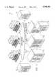
- FIG. 1is an illustration of an exemplary distributed, heterogeneous computer system
- FIG. 2is a block diagram illustrating one embodiment of the present invention
- FIG. 3is one embodiment of a data model of the Catalog database used in one embodiment of the present invention.
- FIG. 4is one embodiment of a data model of the Surrogate Object Type, the Surrogate Object Instance and the Operation Activation structures as implemented in one embodiment of the present invention
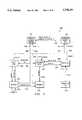
- FIGS. 5, 6 and 7are block diagrams of one embodiment of the present invention illustrating the flow of information at runtime through the elements of one embodiment of the present invention
- FIGS. 8 and 9show exemplary definitions of operation arguments and other properties used to illustrate one embodiment of the present invention.
- FIG. 10defines the object connector symbols used in the exemplary data models shown in FIGS. 3 and 4 in one embodiment of the present invention
- FIGS. 11A-Bis a logic flowchart of an exemplary Operation Requester in accordance with one embodiment of the present invention.
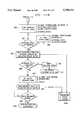
- FIG. 12is a logic flowchart of an exemplary Start Operation Execution function of the Surrogate Object Manager in one embodiment of the present invention.
- FIGS. 13A-Cis a logic flowchart of an exemplary Execute Operation function of the Operation Connection Manager in one embodiment of the present invention.
- the present inventionprovides a method and system of developing applications using reusable components, or executable operations, which are executed upon request of the applications.
- the programmed elements of the present invention, the flow between them and the methods requiredare described in the following sections and illustrated in the attached drawings and flowcharts.
- FIG. 1shows a set of different types of homogeneous computers operable to communicate electronically via computer network 40.
- the computersmay be located in the same building or facility and connected via a local area network, or may be distant from each other and connected via a wide-area network or by use of dial-up modems across telephone lines.
- FIG. 1Three different classes of computer are depicted in FIG. 1 and could be used in an exemplary configuration.
- the classes of computersinclude workstations 22, 24 and 26, mini-computers 28, 30 and 32, and mainframes 34, 36 and 38.
- An exemplary arrangement of the elements of the present invention across the computers in FIG. 1is depicted in FIG. 2.
- FIG. 2is described in more detail hereinbelow.
- Personal computer workstations 22, 24 or 26provide a local processor, data storage and a bitmapped graphical display device for display of application data represented as characters and graphical symbols within an application windows.
- Each of the personal computer workstations 22, 24 and 26also include a user pointing and selection device, such as a mouse, to facilitate user interaction with displayed objects and a keyboard to facilitate character entry.
- the processor of the personal computer workstation 22, 24 or 26is used to execute the instructions comprising the user interface program 90, the Operation Requester 92 and Surrogate Object Definition Module 96 as shown at 72 in FIG. 2.
- the Surrogate Object Manager 94 and the exemplary Operation Connection Managers 104, 118 and 130 of the present inventionare also installed and execute on the processor of each of personal computer workstation 22, 24 or 26 as shown at 72. It is further contemplated, however, that the Surrogate Object Manager 94 and the exemplary Operation Connection Managers 104, 118 and 130 are installed and execute as shared resources among a group of users on the processor of a networked mini-computer server 28 or 32 as shown at 74 in FIG. 2.
- Surrogate Object Type structuresare created in advance of their use in the construction of an application and stored in Surrogate Object Type storage 102 on individual user's personal computer workstations 22, 24 or 26.
- the Surrogate Object Type storage 102is stored on a shareable mini-computer 28 or 32.
- the latter embodiment of the present inventionis more likely if the Surrogate Object Manager 94 is also installed and executes on the mini-computer server 28 or 32. It is contemplated, however, that the invention is used by individuals to define the Surrogate Object Type structures 244 in an ad hoc manner to support their own needs.
- the Surrogate Object Manager 94 and the Surrogate Object Type storage 102are stored on the personal computer workstation 22, 24 or 26.
- Operation Activation and Surrogate Object Instance structuresare stored in the memory of the personal computer workstation 22, 24 or 26 during execution and on the local disk of the personal computer workstation 22, 24 or 26 if required to be persistent between executions.
- the exemplary networked, shareable, mini-computer server 30provides a processor for execution of the Catalog Manager 162, the Operation Enrollment Module 160, the Catalog Editor 148, and the Computer Front-End Module 150 and provides further data storage for the Catalog database 164.
- Shareable mini-computer 28 or 30 or mainframe computer 34, 36 or 38are used to execute operations using exemplary Application Development Tools 152 and 154! and to store the business data manipulated by these operations and stored in exemplary data stores 156 and 158. Such operations and data stores are developed using exemplary Application Development tools 152 and 154.
- the present inventionprovides a Surrogate Object Definition Module 96 which, using information stored in the Catalog database 164 generates a Surrogate Object Type structure 244 which is stored in the Surrogate Object Type storage 102.
- the Surrogate Object Type structure 244, the Operation Activation structure and the Surrogate Object Instance structure, derived from the Surrogate Object Type structure 244,are all used in the collaboration between the Operation Requester 92, the Surrogate Object Manager 94 and the exemplary Operation Connection Managers 104, 116, 130 and 132 to enable an application to invoke an executable operation.
- the executable operation and user interface program 90are to a large extent examples of modules used in exemplary applications, although the present invention provides some guidelines for certain aspects of their design and construction where this impacts their use with the present invention.
- the Operation Enrollment Module 160 and the Catalog Editor 148are also elements of the present invention and are used to populate and maintain the information in the Catalog database 164.
- the preferred implementation of the present inventionuses Microsoft Windows OLE (object linking and embedding) and OLE Automation standards and guidelines for component design of the Operation Requester 92, the Surrogate Object Manager 94 and the exemplary Operation Connection Managers 104, 118, 130 and 132.
- the preferred implementation of all records (of all types) for in-memory useis as OLE component object model (COM) objects.
- COMcomponent object model
- object request brokering and object management technologyincluding that which conforms with the CORBA (common object request broker architecture) from OMG (Object Management Group) or other standard or proprietary architectures would be equally suitable alternatives for implementation of this invention.
- CORBAcommon object request broker architecture
- OMGObject Management Group
- An operationis an executable logic module in a computer system which provides some useful information processing service and offers a well defined execution interface comprising arguments required as input and returned as output.
- An operationmay be implemented on any platform type, operating system, and database management system and in any source code language provided it can be invoked by an appropriate Operation Connection Manager such as exemplary Operation Connection Managers 104, 118, 130 and 132.
- More than one operationmay be implemented in a single executable module, in which case, the module is referred to as an "operation package". If multiple operations are packaged together it must be possible to execute each operation individually within the package.
- Operationsmay be self-contained or they may call other executable modules.
- An operation in the course of executionmay access a persistent data store device to store or retrieve data.
- An operationmay be constructed specifically to provide a "wrapper" for some other unit or units of logic, in which case it will provide some form of data transformation between the representation of its input and output arguments and the input and output arguments of the wrapped module. This approach is an effective means of integrating code modules written at some time earlier.
- Information describing an operationis stored in the Catalog database 164.
- the present inventionthus only needs to determine how to invoke an operation, including a determination as to what data is required as input and what data, if any, is returned. No details of the internal workings of an operation are required other than the descriptive information provided to assist a potential user of the operation to determine its purpose.
- an exemplary operationcould be anything from a simple currency conversion or interest calculation routine, to a module which records the entry of a customer order in a database or extracts a list of products stored in a warehouse from a database.
- any module which needs to access an operationis, in that context, an Operation Requester 92.
- the Operation Requester 92must be operable to communicate with the Surrogate Object Manager 94 but does not necessarily have to be on the same computer as the Surrogate Object Manager 94.
- An exemplary use of the inventionincludes the use of operations implemented on a mini-computer or mainframe server computer and Operation Requesters 92 implemented as modules either called by or within a user interface program 90 running on a client workstation 22, 24 or 28 which provides an application window 84, 86 or 88.
- the Operation Requester 92might be implemented as a macro in the macro language of a desktop tool such as Microsoft's Excel, or as a subroutine in a programming languages such as Microsoft's Visual Basic or Visual C++.
- the present inventionenables the use of tools such as Excel and other desktop productivity products to build Operation Requesters 92. This reduces the skill level required for a user to participate in application development and allows more business-oriented users to "assemble" operations into their own applications.
- the Catalog database 164is a shared data storage facility which includes descriptions of executable operations and the definitions of their execution interface requirements. Management of the data stored in the Catalog database 164 is enabled by the Catalog Editor 148 which provides a user interface for entering, displaying and updating Catalog records and properties, the Catalog Manager 162 which provides a set of access and data storage functions that allow Catalog records in the Catalog database 164 to be added, updated and deleted while at all times enforcing the rules imposed by the Catalog data model 180 shown in FIG. 3 and described in more detail hereinbelow.
- the Catalog 82enables the representation of a unified high-level business model of the arguments of multiple operations where those operations manipulate common facts in their input and output arguments. This unified representation is achieved by associating individual operation arguments with common predicates of shared entity types. This requires specific types of information to be available in the Catalog 82.
- FIG. 3is a diagrammatic representation of the preferred data model for the record types stored within the Catalog 82, depicting the types of data stored and the relationships between them.
- boxesare used to represent logical record types and the lines between them represent types of relationship between these records.
- the relationship lines shown in FIGS. 3 and 4, as described in FIG. 10,further indicate optionality, cardinality and sequence requirements of the relationships.
- the physical data model of an implementation of the Catalog database 164may vary from that described above for reasons of optimizing storage or improving retrieval performance. It is contemplated that different implementations of the Catalog database 164 of the present invention may include the use of flat files, relational databases or object oriented databases. However, any implementation must provide storage functions that support the conceptual data model of the Catalog database 164 as illustrated in FIG. 3.
- the preferred implementation of the present inventionuses a relational database and implements each record type as a table and each relationship using a foreign key pointer.
- the Catalog database 164 record types and their propertiesare the same as those required in the Surrogate Object Type structure 244 and are described hereinbelow. There are, however, small but crucial differences between the data model of the Catalog shown in FIG. 3 and the data model of the Surrogate Object Type structure 244 shown in FIG. 4. Operations can be defined in the Catalog database 164 before any Surrogate Object Type structures 244 have been defined, thus making the relationship at 194 between the operation 210 and the corresponding instance of the Surrogate Object Type 186 optional in the Catalog database 164.
- the Surrogate Object Type structures 244can overlap with one another with regards to the operations they include and may have the same entity type 196 as the core, as shown by the relationship at 192.
- the relationship at 192 between entity type 196 and surrogate object type 186 and the relationship at 194 between the operation 210 and the surrogate object type 186allow associations with many instances of the surrogate object type 186.
- the present inventionmay use the information stored in some other Catalog or development repository as long as it is possible to determine the operation definition information required by the present invention from the information stored in the other Catalog or repository.
- the operation definition information from some other Catalog or repositorycan be loaded into the Catalog database 164 using the Operation Enrollment Module 160. Such loading of operation definition information is referred to as “enrolling” and is described in more detail hereinbelow.
- the Catalog database 164may be populated manually using the Catalog Editor 148.
- the Catalog database 164may also be populated directly by development tools if the implementation of the Catalog database 164 is a repository shared with automated application development tools 152 and 154 which use the repository to store information during the process of developing the operations. Such tools are often referred to as computer aided software engineering (CASE) tools.
- CASEcomputer aided software engineering
- the Catalog database 164can further be populated from some other electronically held source of information.
- a sourceincludes some other development repository or some other suitable external source of operation definition information.
- a wide variety of possible external sourcescould be used, including the repositories and definition files used by various CASE tools, data dictionary products and existing program source code, or through some direct interface with an executing operation capable of describing its own structure in a manner suitable for capture and enrollment.
- Enrollment of such externally held operation definition informationis accomplished with an Operation Enrollment Module 160.
- Each different source of informationmay require a specially designed Operation Enrollment Module 160 which is capable of mapping the operation definition information from the source format into the format required by the Catalog database 164.
- the Operation Enrollment Module 160assists by automating some or all of the enrollment of operation definitions into the Catalog database 164 or repository from an external electronically held source.
- Potential sourcesinclude CASE tool repositories, data dictionaries and program source code. Operation enrollment is also possible from "self-describing" operations that offer functions that return definitions of their input and output arguments.
- Operation enrollmentinvolves the transformation of information from a source-specific data representation into the representation supported by the Catalog database 164 (see the Catalog database 164 data model shown in FIG. 3.). As a result, different types of source are likely to require different Operation Definition Modules.
- Operation Enrollment Module 160One function of the Operation Enrollment Module 160 is the construction of a arguments of operations being enrolled. To achieve this, the model is built up with each successive operation as it is enrolled.
- the arguments of each operation being addedare matched to predicates 220 already in the Catalog database 164 and either associated with existing predicates 220 and entity types 196 in the Catalog data model as shown in FIG. 3 or, if necessary, new predicates 220 and entity types 196 are added, or in the case where the arguments are determined to be operation specific, then no predicate is created. This matching is done both on first enrollment of the operations and on subsequent re-enrollment if the operation has been updated.
- Matchingis based on the source -- names on the Catalog database 164 records for operation, argument groups and individual arguments, as well as on a comparison of individual argument properties with predicate properties.
- operation enrollmentmay be more or less automated. If the source holds information in the same or similar format to the information in the Catalog database 164, a high degree of automation is likely. Otherwise, enrollment will require operator assistance to resolve inconsistencies or to augment the information available from the source.
- An implementation of the Catalog Enrollment Module 160may enable operator intervention to occur during the course of enrollment or the Catalog Editor 148 can be used afterwards to modify the enrolled operation data.
- Catalog Editor 148Manual input of operation definition information is supported by the Catalog Editor 148 which provides a user interface 146 that allows direct entry of Catalog database 164 records in situations where it is deemed impractical or undesirable to develop an automated operation enrollment capability.
- the Catalog Editor 148is also used to maintain operation definitions once enrolled, regardless of their original source.
- Catalog database 164 record propertiescan be added or modified, and associations between operation arguments and predicates can be added or deleted to reflect increased or changed understanding of the business meaning of the arguments of operations.
- Creation of a Surrogate Object Type structure 244involves copying a collection of records and their properties from the Catalog database 164.
- the Surrogate Object Definition Module 96provides a user interface that enables the operator to browse and examine operation descriptions and definitions held in the Catalog database 164. The operator then selects one or more of these operations and requests these be used to create a Surrogate Object Type structure 244. This is done through interaction of the Surrogate Object Definition Module 96 with functions of the Surrogate Object Manager 94 which causes the selected operations and their related objects to be replicated from the Catalog database 164 into a Surrogate Object Type structure 244 which is stored in Surrogate Object Type storage 102.
- the Surrogate Object Definition Module 96is also used to maintain previously constructed Surrogate Object Type structures 244. It enables the operator to examine and modify the existing Surrogate Object Type structure 244 contents, and if required, to update existing or add new operation definitions from the Catalog database 164.
- the Surrogate Object Definition Module 96is also used to enable the operator to record whether or not instance mapping support is to be enabled for a Surrogate Object Type structure 244. If instance mapping support is enabled, the Surrogate Object Definition Module 96 permits the operator to examine the input and output arguments of each operation included in the Surrogate Object Type structure 244, and to define which arguments will be mapped to predicate values in a Surrogate Object Instance.
- Surrogate Object Type definitionscan also be stored back into the Catalog database 164, thus enabling these definitions to be re-used by others.
- the Surrogate Object Type Definition Module 96can be designed to apply appropriate data transformations to the information extracted from the Catalog database 164 or repository, thus enabling creation of the Surrogate Object Type structure 244 records as required.
- the Surrogate Object Manager 94is module which implements a set of externally addressable functions which in turn provide services that manipulate occurrences of the three structure types created in the course of using the present invention: the Surrogate Object Type structure 244; the Operation Activation structure and the Surrogate Object Instance structure.
- the Surrogate Object Manager 94provides access to the data held in these three data structures.
- a Surrogate Object Type structure 244is a named collection of records that describes one or more operations and describes and defines their input and output arguments.
- a Surrogate Object Type structure 244is created by the Surrogate Object Definition Module 96 from information extracted from the Catalog database 164.
- each Surrogate Object Type structure 244is stored in a suitable persistent form in the Surrogate Object Type Storage file 102.
- the preferred storage implementationuses OLE structured storage, enabling a Surrogate Object Type structure 244 to be stored as an embedded object within an OLE compound document file. This enables the Surrogate Object Type structure 244 to be stored together with the Operation Requester 92 and other parts of the application. It is preferred that each Surrogate Object Type structure 244 is stored independently. As a result, information in one Surrogate Object Type structure 244 may be duplicated in another. This duplication enables storage and retrieval times to be optimized and ensures that each structure is always complete and usable, with no dependency between structures.
- a Surrogate Object Type structure 244may be created to represent some type of element of significance to the business in which case it provides a surrogate "business object” or "business object type” (BOMSIG reference). Examples of this kind of use include Surrogate Object Type structures 244 created to represent a customer, an order form or an insurance proposal. The operations included in a customer Surrogate Object Type structure 244 may include Add -- Customer, Get -- Customer -- Credit -- Rating, and Change -- Customer -- Details.
- a Surrogate Object Type structure 244may be created as a task-related object, combining the operations required to service the needs of some computer or user task.
- a Surrogate Object Type structure 244may be created to provide a set of domain-related services and may further include a set of operations which manipulate values for date and time, or provide currency conversion, or provide standard algorithms such as tax or interest calculation, or provide utility functions, such as string searches, spell checking, or printing.
- the surrogate object type record 314holds the definition of the Surrogate Object itself and provides the root record for the other record types in the Surrogate Object Type structure 244.
- “Surrogate Object Type”the term refers to the structure; when written thus, “surrogate object type”, the term refers to the root record type within such a structure.
- the surrogate object type record 314always includes one or more operations represented by an operation record 304. These are the operations which can be invoked from the Surrogate Object Type structure 244.
- a surrogate object type record 314may also include one or more instances of the predicate instance mapping record 266.
- the surrogate object type record 314is required if instance mapping is enabled for the Surrogate Object Type structure 244.
- An instance of the predicate instance mapping record 266exists for each instance of the argument record 288 and is used as a source of instances of the predicate value record 260 in the Surrogate Object Instance structure 242.
- the same instance of the predicate record 282can be sourced from more than one instance of the argument record 288 of more than one instance of the operation record 304.
- Instances of the surrogate object type record 314may have only one core instance of the entity type record 276 which is optional.
- a core instance of the entity type record 276is required if instance mapping is enabled for the Surrogate Object Type structure 244.
- the instance of the entity type record 276indicates the type of thing upon which the Surrogate Object Type structure 244 is based.
- the identifier of the instance of the entity type record 276is used as the identifier of Surrogate Object Instance structures 242 based on the current Surrogate Object type structure 244.
- Instances of the operation record 304store the definition of an executable operation intended to be accessible using the present invention.
- An instance of the operation record 304is always included in an instance of the surrogate object type object 314.
- An instance of the operation record 304is always of only one operation type record 312. Different instances of the operation record 304 within the Surrogate Object Type structure 244 may be associated with different operation type records 312.
- An operationsometimes outputs one or more sequenced argument groups 296, shown by the "output from” relationship at 300.
- the "output from” relationship at 300 and the “contains” relationship at 290 between argument record 288 and argument group record 296are sequenced so that the sequence that the individual output arguments occur in can be retained.
- An operationsometimes inputs one or more sequenced argument groups, shown by the "input to" relationship at 302.
- the "input to" relationship at 302 and the “contains” relationship at 290 between argument record 288 and argument group record 296are sequenced so that the sequence that individual input arguments occur in can be retained.
- the execution -- parametermay be in any format understandable and meaningful to the Operation Connection Manager 104, 118, 130 or 132 and/or other communications-related components which are executed by the Operation Connection Manager 104, 118, 130 or 132 as part of the process of invoking the operation.
- the Operation Connection Manager 104, 118, 130 or 132may translate or transform this information using some directory service or use some other means of determining or acquiring necessary location information so that the operation can be executed.
- the operation type record 312defines the type of an executable operation.
- the operation type record 312is also used to hold information applicable to a number of operations of the same type.
- An operation type record 312always groups one or more executable operations.
- the entity type record 276is a meaningful collection of predicates stored in the predicate record 282.
- the entity type represented by the entity type record 276normally represents an important thing in the business.
- An entity type record 276always includes one or more sequenced predicate records 282.
- An entity type record 276is sometimes identified by one or more sequenced predicate records 282. This relationship must exist if Surrogate Object Instance structures 242 are to be supported for the Surrogate Object Type structure 244, in which case this relationship is required only for the core entity type record 276 of the surrogate object type record 314, described in more detail hereinbelow.
- the identifying predicate records 282are used to identify Surrogate Object Instance structures 242.
- An entity type 276is sometimes the core of only one surrogate object type record 314. If Surrogate Object Instance structure 242 support is enabled, only one entity type 276 is defined as the core entity type 278. Predicates 282 of non-core entity types 276 can also be represented by arguments 288 of included operations 304.
- An entity type 276is sometimes represented in one or more argument groups 296.
- Surrogate Object Instance structure 242 supportrequires the ability to identify a group of an operation's output arguments as being a view of an instance of an entity type 276. Values from these arguments 288 are then used to populate predicate values 260 in a Surrogate Object Instance structure 242.
- a predicate 282is an important business fact which describes an entity type 276.
- a predicate 282may be an attribute of the entity type 276 or it may be part of a relationship with another entity type 276.
- "name”might be an attribute of the "customer” entity type 276.
- a predicate 282always describes only one entity type 276.
- a predicate 282sometimes identifies an entity type 282.
- the identifier of an entity type 276may include more than one predicate 282.
- a predicate 282is always represented by one or more arguments 288.
- a predicate 282also defines the underlying business meaning implied by an argument 288. Association with the arguments 288 of multiple operations 304 enables the indication of common meaning among the arguments 288.
- a predicate 282sometimes defines one or more predicate values 260. Not all Surrogate Object Type structures 244 need be used as the basis of Surrogate Object Instance structures 242. And for those that are, not all predicates 282 of the included entity types 276 need be stored as predicate values 260.
- An argument 288is a data item which is either input to or output from an operation 304.
- An argument 288is sometimes a representation of one predicate 282. Where an argument 288 is not associated with a predicate 282, then it is assumed to be an operation-specific variable with no meaning beyond its use by the operation 312.
- An argumentis always part of one argument group 296.
- the arguments 288 of a specific operation 312may be arranged into a hierarchical structure of argument groups 296. At a minimum, each argument 288 will be associated with a highest-level argument group 296 which directly or indirectly includes all the input or all the output arguments 288 of an operation 304.
- An argument group 296is a meaningful collection of either input or output arguments 288 of a single operation 304 and is used to indicate structure within the arguments 288 of an operation 304.
- An argument group 296is also used to distinguish arguments 288 which are representations of predicates 282 of different instances of the same entity type 276.
- An argument group 296is further used to indicate where a group of arguments occurs multiple times in the input or output of an operation 304.
- An argument group 296is sometimes output from only one operation 304.
- An argument group 296is sometimes input to only one operation 304.
- An argument group 296is sometimes part of only one other argument group 296.
- Argument groups 296are further used to define hierarchical structure among the data items input to or output from an operation 304. At the top of the hierarchical structure, the topmost argument group 296 is associated with the operation 304 either as input 302 or output 300. Individual arguments 288 form the leaf-nodes of the hierarchical structure.
- An argument group 296sometimes includes one or more sequenced argument groups 296 which is an inverse of the relationship indicated hereinabove.
- An argument group 296may also include one or more sequenced arguments 288 and must include either another argument group 296 or arguments 288.
- a predicate instance mapping 266is only required if Surrogate Object Instances 248 are to be enabled for the Surrogate Object Type structure 244.
- a predicate instance mapping 266defines an intersection between an argument 288, a predicate 282 and the surrogate object type record 314.
- a predicate instance mapping 266always defines the source of a predicate 282 in an instance of one Surrogate Object Type structure 244.
- a predicate instance mapping 266always maps to one argument 288.
- a predicate instance mapping 266always maps to one predicate 282.
- an associated predicate instance mapping 266indicates that argument values defined by this argument 288 are mapped to the corresponding predicate value 260 in the Surrogate Object Instance structure 242. If there are no predicate instance mapping objects 266 for a predicate 282, no corresponding predicate values 260 will exist in any Surrogate Object Instance structure 242.
- an associated predicate instance mapping 266indicates that the corresponding argument value is mapped from the corresponding predicate value 260 in a Surrogate Object Instance structure 244 prior to operation execution. For predicates 282 other than identifying predicates 282 this can be overridden by a value provided by the Operation Requester 92.
- transformation between the format of the predicate 282 and the format of the argument 288is defined by the mapping -- rule defined on the argument 288.
- Predicate values 262 stored in the Surrogate Object Instance structure 242are held in the format defined by the predicate 282.
- arguments 288must include arguments 288 which are representations of all of the set of predicates 282 which form the identifier of the core entity type 276 of the Surrogate Object Type structure 244.
- the predicate instance mapping 266is identified by the combination of its relationships with argument 288, predicate 282 and surrogate object type record 314.
- An Operation Activation structure 246is a collection of records that together represents an occurrence of the activation (invocation) of an operation 304 defined within a Surrogate Object Type structure 244.
- the Operation Activation structure 246provides a "staging area", which enables the input and output arguments 288 to be assembled into an operation-neutral format prior to the operation 304 being invoked and after execution.
- the Operation Activation structure 246is implemented so that the relationships between the operation and operation activation records can be traversed in either direction.; i.e., it must be possible to determine all the operation activations for a given operation, and from a given operation activation, determine what operation it is for.
- Each individual Operation Activation structure 246 based on a single root operation activation recordcan be saved to the Operation Activation Storage file 100 as an option. This permits a form of operation activation logging.
- the preferred implementationdoes not require this persistence as an Operation Activation structure 246 is normally only required by an Operation Requester 92 for the duration of an operation activation "cycle", during which time the Operation Activation structure 246 is maintained in computer memory.
- output argumentsare either retrieved immediately by the Operation Requester 92 and/or they are mapped to predicate values 260 in a Surrogate Object Instance structure 242 which can then be saved to the Surrogate Object Instance Storage file 98.
- Surrogate Object Manager 94 processingis terminated, all unsaved Operation Activation structures 246 are lost.
- An operation activation record 316is the root of an Operation Activation structure 246 and holds details of a single invocation--or activation--of an operation 304, including time of activation, user-id of person requesting activation, execution status, error message etc.
- Operation Activationthe term refers to the structure; when written thus, “operation activation”, the term refers to the root record type within such a structure.
- An operation activation record 316always records the invocation of only one operation 304.
- An operation activation record 316sometimes has as input one or more argument value groups 324.
- An operation activation record 316sometimes has as output one or more argument value groups 324.
- An Operation Activation structure 246is identified by a combination of its associated operation and the activation -- ID.
- An argument value 328holds the value for an argument for a specific operation activation 316.
- each argument value 328is implemented as a slot in a record which includes either all the input or output argument values, arranged according to the sequence and structure defined by the argument value groups 324.
- the relative position of each argument value 326 within the recordcorresponds to the relative position of the defining argument within the operation input or output argument structure.
- An argument value 326is always part of one argument value group 324.
- the Surrogate Object Instance structure 242provides a form of local "database” comprising a collection of records which hold data representing one or more instances of a common surrogate object type record 314.
- the Surrogate Object Manager 94functions which offer access to these records in the Surrogate Object Instance structure 242 act as the database engine.
- a Surrogate Object Instance structure 242comprises possibly multiple "root" surrogate object instance records, together with one or more entity records each with one or more predicate value slots. Each entity and predicate value is created from the output of one or more operations after their execution. Individual arguments are mapped to predicate value slots based on the predicate instance mappings defined in the Surrogate Object Type structure 244.
- the exact structure of the records included within a Surrogate Object Instance structure 242will depend upon a combination of the definition of the Surrogate Object Type structure 244, which operations have been invoked and with what input arguments, the state of the data currently held on the application databases accessed by the operations and the rules included within the operation logic.
- the Surrogate Object Instance record type 248represents the root object of the Surrogate Object Instance structure 242 and collects together the set of predicate values which together hold the instance data.
- “Surrogate Object Instance”the term refers to the structure; when written thus, “surrogate object instance”, the term refers to the root record type within such a structure.
- the entity 254represents an occurrence of an entity type 276.
- the entity 254collects together the predicate values 260 that hold the data stored about the entity 254.
- An entity 254is identified by the values in the predicate slots that correspond to the predicates that form the identifier of the entity type 276. Each of these slots must hold a valid value.
- An entity 254sometimes is the core of a Surrogate Object Instance structure 242.
- An entity 254always includes one or more predicate values 260.
- An entity 254is always is defined by one entity type 276.
- a predicate value 260holds the value of an individual predicate 282 within an entity 254.
- each predicate value 260is a slot in an entity record.
- Each predicate 282 in the setdefines the corresponding predicate value 260.
- a predicate value 260always is included in one sequenced entity 254.
- a predicate value 260is sometimes paired with one predicate value 260.
- the predicate value 260is paired with a predicate value 260 belonging to an entity 254 of the related entity type 276. This provides a navigable pointer pairing mechanism allowing relationship pairings between entities 254 to be traced.
- a predicate value 260is always defined by one predicate 282.
- the Operation Connection Manager 104, 118, 130 or 132provides a generalized runtime connection capability enabling the Surrogate Object Manager 96 to trigger execution of an implemented operation.
- An Operation Connection Manager 104, 118, 130 or 132will be required for each set of operations which support a consistent interface protocol. Operations built by a common tool in a common style may all be able to use the same Operation Connection Manager 104, 118, 130 or 132.
- any distributed process server (DPS) module built with Composer by IEFfor example, regardless of the platform on which the DPS module executes, can be accessed by the same Composer Operation Connection Manager 104. Similar use of a common Operation Connection Manager 130 or 132 is likely to be possible for operations built by other application development tools.
- DPSdistributed process server
- the Surrogate Object Manager 94 and the appropriate Operation Connection Manager 104, 118, 130 or 132will collaborate to ensure the input arguments in the Operation Activation object 316 are formatted and defined in the manner expected by the operation, and communicated to the operation using the appropriate communication protocol.
- the Operation Connection Manager 104, 118, 130 or 132is responsible for applying input and output transformation rules to transform data between the format stored in the Operation Activation structure 246 and the operation message format and back again.
- the Operation Connection Managers 104, 118, 130 or 132can be written to accommodate operations which expect fixed or variable length message structures, in a pre-defined sequence or with embedded tags describing the arguments. Data compression or encryption algorithms can also be incorporated as required on both input and output.
- the input and output transformation rules and data marshaling rulescan be coded as part of the Operation Connection Manager 104, 118, 130 or 132, or can be retrieved from some external source to be evaluated at execution time.
- the Operation Connection Manager 104, 118, 130 or 132is responsible for monitoring operation progress including operation completion and the detection of various possible error conditions. In the case of successful completion, the Operation Connection Manager 104, 118, 130 or 132 decodes the returned data into the set of output argument values in the Operation Activation structure 246.
- the present inventionprovides for any number of different Operation Connection Managers 104, 118, 130 or 132 to be used simultaneously by the Surrogate Object Manager 94. Differences between operation types are thus made transparent to the Operation Requester 92.
- Operation Connection Managers 104, 118, 130 or 132are built in advance by a user of the present invention in accordance with the specific operation types, or developed and sold by application development tool vendors as part of their commercial offerings.
- Scenario 1illustrated in FIGS. 5 and 6, show the simplest use of the present invention with a user interface program 368 which provides any required transient or persistent management of the data returned by the operations.
- Scenario 2, illustrated in FIG. 7,is an extension of scenario 1 and illustrates in more detail the use of the Surrogate Object Instance feature of the present invention.
- the user interface program 572makes use of the facilities provided by the system to manage instance data returned by the operations.
- the Surrogate Object Manager 614 functionsare used to create and manage discrete surrogate object instances, one per customer record that has been accessed by an operation. Each surrogate object instance is accessible individually and can be made the subject of operation requests.
- each of the exemplary operationsinvolves either creating, reading or updating of customer records stored in a shared customer database 424, 524 or 640. These four operations behave as follows:
- Add -- Customercreates a customer record in an application database with values for name, address and phone number as supplied in the operation input arguments and returns in addition the unique customer number created to identify the new customer record.
- List -- Customersreturns a list of the customer number and name stored on each customer record in the database.
- Get -- Customer -- Detailsrequires a customer number. If a matching customer record is found in the database, the operation returns the name, address and telephone number stored therein.
- Change -- Customer -- Detailsrequires the customer number and optionally, the name, address and telephone number. If the customer is found, then the supplied values for name, address and telephone number will be used to replace those in the database.
- the four operations, Add -- Customer, List -- Customers, Get -- Customer -- Details, and Change -- Customer -- Detailshave been developed using a common tool, i.e., Composer by IEF, so they share a common protocol for execution and argument passing.
- all these operationscan be connected to the Surrogate Object Manager 390 via a single, common Operation Connection Manager, shown in FIG. 7 as the Composer Operation Connection Manager 394.
- the Composer Operation Connection Manager 394uses the Composer Communications Module 406 to communicate with the computer system on which the operation package 412 is implemented via the computer front-end module 410 associated with that computer system.
- the computer front-end module 410assists in routing the operation request to the operation and the response back.
- Get -- Customer -- Credit -- Ratingis implemented on a different computer system, is developed in a different language with a different tool, uses a different database and runs under a different operating system. (In this scenario, this operation is, for example, part of an older information system which would otherwise be difficult to integrate with the newer operations in the Customer operation package 412 at runtime.)
- Get -- Customer -- Credit -- Ratingavailable as an operation of the Customer Surrogate Object Type, the present invention makes it appear indistinguishable from the other newly-built operations to the person developing the Operation Requester 378.
- the operation Get -- Customer -- Credit -- Ratingis accessed using the 3270 message protocol through the 3270 Terminal Emulation Module 434 and the Computer Front-End Module 438.
- This communication protocolis a de facto standard for screen-based communication between IBM-compatible computers and "dumb terminals".
- the 3270 protocoldefines how information to be displayed on a screen is packaged into a data stream.
- the data streamincludes the data to be displayed together with various control codes which are interpreted by the display terminal. Interception of this data stream at the terminal end by the terminal emulation software running on some other kind of computing device (i.e. a personal or server computer as opposed to a "dumb terminal") enables this data stream standard to be used to communicate with compatible operations implemented on IBM-compatible mainframes. This is particularly suitable if it is desired to make use of application components already in existence which were written initially to use this communication protocol.
- the present inventionprovides the ability to incorporate older, pre-existing communication technology and thus integrate access to a wide range of existing applications as well as applications specifically designed to exploit the present invention.
- Other standard messaging protocolscould similarly be used whether screen oriented or not.
- a specialized 3270 Operation Connection Manager 426, 528 or 642is shown.
- the specialized 3270 Operation Connection Manager 426, 528 or 642is responsible for mapping operation input arguments into a 3270 data stream and sending it to the host for processing, and then for receiving the 3270 data stream sent back in response and for identifying the output arguments within the 3270 data stream and mapping these output arguments back into the form understood by the present invention.
- the layout of information on each screenfrequently varies from screen to screen--i.e. the row/column starting position and length of fields and text strings.
- this layout informationaffects the relative position of data and other elements within the 3270 data stream, this information is required to enable the 3270 Operation Connection Manager 426, 528 or 642 to map the operation arguments into and out of the data stream.
- other control codesmay need to be entered into the data stream, or multiple interactions between the 3270 Operation Connection Manager 426, 528 or 642 and the host may be required to cause the host system to be put in a state ready to execute the operation.
- This informationis likely to include user log-on and access, via menus and other control mechanisms, to the correct "screen" on which the operation data is represented.
- This navigation and formatting informationwill normally be different for each operation, although re-usable for every execution of the same operation.
- This "script" informationcould be written into the logic of the 3270 Operation Connection Manager 426, 528 or 642 or stored externally in Script File Storage 432, 536 or 648 as a set of parameters which are accessed and interpreted whenever the operation is to be executed.
- script informationis required to enable the 3270 Connection Module 426, 528 or 642 to correctly locate and execute the Get -- Customer -- Credit -- Rating operation 442.
- External storage of thisis assumed and illustrated in FIGS. 5, 6 and 7 in the Script File Storage 432, 536 or 648, respectively.
- the Operation Connection Manager 426, 528 or 642is expected to be a common module used to connect many operations with similar connectivity characteristics into the system. If a new type of operation is being used for the first time a new Operation Connection Manager may have to be constructed, otherwise one should already exist.
- the operation of the Operation Connection Manager 426, 528 or 642is illustrated in the flowchart shown in FIG. 13.
- the present inventionallows the simultaneous use of multiple, different Operation Connection Managers. It must be possible for any Surrogate Object Manager that has to access an operation to be able to locate the Operation Connection Manager for that type of operation. It may be that the Operation Connection Managers will be co-located with the Surrogate Object Managers, perhaps on a user's desktop machine, or they may be located on a shared computing resource and re-used by multiple Surrogate Object Managers. Both scenarios 1 and 2 require a Composer Communications Module 406, 508, or 624 and a 3270 Terminal Emulation Module 434, 538 or 650 to be present.
- Catalog database 64Information representing an operation and its input and output arguments must be stored in the Catalog database 64 before it is accessible through the present invention. If the Catalog database 64 being used for the present invention is shared with the development tools used to develop the operation code, then this information may be present as a result of the normal development process. If the operation has been developed from a separate development repository then this information may be enrolled using an Operation Enrollment Module 160.
- Operations which have been manually written or built using a tool for which a specific Operation Definition Module 82 is not availablecan be input manually using an Operation Enrollment Module 160 that supports manual entry.
- the operationsare either built with Composer or they are existing 3270-based operations.
- information about the operationshas been stored in Composer's development repository and is extracted and enrolled into the system's Catalog database 64 using an Operation Enrollment Module 160 designed for the purpose.
- the Operation Enrollment Module 160captures properties of each operation and associates each operation with an operation type object, and then maps the definition of each operation's input and output arguments from a Composer-proprietary representation to the representation defined in the data model of the Catalog database 64 as illustrated in FIG. 3.
- a key function of the Operation Enrollment Module 160is the construction of a normalized model of the underlying set of business facts that are represented by the arguments of operations being enrolled.
- the modelis built up with each successive operation as it is enrolled.
- the arguments of each operation being addedare matched to predicates in the model as it already exists.
- the argumentsare either associated with existing predicates and entity types in the model or if necessary, new ones are added.
- mapping and validation rulesmay be specified. Mapping rules allow a transformation to be described between the format of an argument and the predicate. In this way minor variations in the representation of common concepts can be supported.
- mapping -- rule property on both input and output argument objectsis used to store the rule.
- This mapping -- rulewould define format and domain transformations between the predicate and the arguments affecting things such as left or right alignment, character padding, null characters representation, addition or removal of currency symbols, numeric to character conversion and etc.
- the mapping -- rule on the input argumentwould be applied before operation execution; the mapping -- rule on the output argument would be applied after execution.
- Validation rules stored in the Catalog database 64enable arguments to be verified prior to operation execution.
- Validation rulescan be stored in the validation -- rule property on a predicate, on an input argument, or on the operation.
- Validation rule processingis invoked on request by the Operation Requester 92 to validate an operation's input arguments, perhaps as they are entered through the user interface, or immediately before invoking the operation as shown in the operation of the Operation Requester 92 illustrated in the flowchart shown in FIG. 11.
- the present inventiondoes not specify a particular rule language for either the validation or mapping rules. Any procedural or declarative rule language can be used and implemented in the design of the Validate Input Argument and Validate Operation Input functions of the Surrogate Object Manager 94. The point at which these functions are invoked is indicated in the flowcharts shown in FIGS. 11-13. It is contemplated that a corresponding rule parser and checker could be usefully included as part of the Operation Enrollment Module 160 to assist in the correct definition of rules upon entry to the Catalog database 64.
- Both scenariosare based on the creation and use of a Surrogate Object Type created to represent a customer business object.
- a customer business objectrequires a collection of operations which act upon customer information.
- the Surrogate Object Definition Module 96is used to browse among the operations that have been enrolled into the Catalog database 64 to locate those to be included in the Surrogate Object Type.
- Surrogate Object Typemight support instance mapping (i.e., the creation of Surrogate Object Instances)
- a core entity typemust be defined. If this is done, it is likely, but not essential, that the operations to be included will all have arguments which represent predicates of the core entity type. Only those operations whose output arguments include representations of all of the identifying predicates will be able to participate in instance creation.
- the Surrogate Object Definition Module 96calls the function Create -- SOT -- Structure of the Surrogate Object Manager 94 passing it information about the selected objects.
- the Create -- SOT -- Structure functioncreates an instance of the Surrogate Object Type structure 244 with a root surrogate object type record with name of "Customer.”
- the Create -- SOT -- Structure functionalso populates the structure with records replicated from the Catalog database 64 including the selected operations, their associated operation type(s), their input and output arguments, each argument's associated predicates and the entity types these predicates belong to.
- the Surrogate Object Type structure 244When complete, the Surrogate Object Type structure 244 includes a replicated subset of the information held in the Catalog database 64.
- the Surrogate Object Type structure 244includes all the information required to support the execution of the operations defined within it. Further minor modification to the properties of objects included within the Surrogate Object Type structure 244 can be carried out with the Surrogate Object Definition Module 96 without further contact with the Catalog database 64.
- the Surrogate Object Type structure 244is saved in a persistent form in the Surrogate Object Type Storage file 100 by invoking the Save -- SOT -- Structure function of the Surrogate Object Manager 94.
- Surrogate Object Typescan be created in advance of their planned use by the Operation Requester 92 or can be created as and when needed.
- the Surrogate Object Type structures 244can be distributed to wherever they may be required.
- the Operation Requester 92 and user interface program 90are now built. In both scenarios, the Operation Requester 92 is called by the user interface program 90 which enables data to be entered by the end-user, each operation to be executed and any returned data to be viewed.
- the screen generated by and the behavior of the user interface program 90provide the means by which the user can activate the operations executable using the present invention and to observe their effect.
- the user interface program 368provides any required desktop persistence of data between operation executions. In a simple solution, this is likely to be done using in-memory data structures. In this way data values returned as output arguments of one operation can be re-used as input argument values for a subsequent operation execution without re-entry by the user. Values can be retained in in-memory structures for as long as the user interface program is running but will be lost when it is stopped.
- a more complex solutionmight provide persistence across multiple sessions, storing important data values in some non-volatile storage medium.
- provision of any such capabilitywould be the responsibility of the programmer of the user interface program 368 and is not provided for by the system.
- revision #3 of the Visual Basic language and product from Microsoftis used to construct the Operation Requester 378, 482 or 582 and the user interface program 368, 476 or 572.
- Appropriate codeis written to trigger operation execution and to map input and output arguments into the Operation Activation structure 246 via the functions offered by the Surrogate Object Manager 390, 498 or 614. This will be accomplished if the developer constructs the logic of the Operation Requester 378, 482 or 582 in accordance with the preferred logic shown in the flowchart illustrated in FIG. 11.
- the Surrogate Object Type structure 244is examined using the Surrogate Object Definition Module 96. This enables the programmer to determine the correct operation names and argument names to use in construction the program logic statements required to invoke the required Surrogate Object Manager 390, 498 or 614 functions.
- the Surrogate Object Manager 390, 498 or 614supports pre-defined functions, it is contemplated that standard application development tools could be built to automatically generate some or all of the code of the Operation Requester 378, 482 or 582 based on the contents of the Surrogate Object Type structure 244.
- Operation Requester 378, 482 or 582 and the user interface programs 368, 476 or 572are deployed onto the intended computing platform ready for use. In these scenarios, this could be a desktop personal computer running the Microsoft Windows operating system.
- FIGS. 5 and 6show data flows through specific elements of the present invention and depict the appearance of the user interface and data content of the databases before and after use of the present invention.
- the operation of the Operation Requester 378 or 482, illustrated in the flowchart shown in FIG. 11; the operation of the Start -- Operation -- Execution function of the Surrogate Object Manager 390 or 498, illustrated in the flowchart shown in FIG. 12; and the operation of the Execute -- Operation function of the Operation Connection Manager 394, 426, 502 or 526, illustrated in the flowchart shown in FIG. 13,further illustrate certain aspects of the data flow of one embodiment of the present invention.
- the userinteracts with the present invention entirely through an application window 352 presented by the user interface program 368.
- the application window 352permits the user to enter new customer details and request that a new customer record is created.
- This requestis passed on via the appropriate Operation Connection Manager 394 or 426 and the operation is executed.
- This operationcreates a new customer record in the customer database, using the details entered by the user and assigns the record a new identifying customer number.
- the user interface program 368calls the Operation Requester 378 again, this time to invoke the Get -- Customer -- Credit -- Rating operation, which searches the credit database 444 for the customer by name and returns the customer's credit rating if found.
- FIG. 6shows one embodiment of the present invention in accordance with the scenario illustrated in FIG. 5 immediately after the user has entered the customer details but before requesting that the record is added.
- FIG. 7shows another embodiment of the execution of the present invention in accordance with a second scenario after successful completion of the addition and the credit rating search.
- the userfirst starts the user interface program 368 from the Windows program manager.
- the user interface program 368displays the Create New Customer application window 352 and then waits for user input.
- the userenters values for customer name, address and telephone number, and then with the keyboard or a pointing device selects the push-button marked "Add" 360 to indicate that data entry is complete and that a new customer is to be created.
- the Operation Requester module 378then calls a series of functions of the Surrogate Object Manager 390.
- the Operation Requester module 378calls the Create Operation Activation function using the SOT.name and operation.name as shown at block 952 in FIG. 11. This function loads the Customer Surrogate Object Type structure 244 from storage if not already loaded and creates an Operation Activation structure with its operation activation record associated with the operation Add -- Customer.
- the Operation Activation structureis created with the appropriate input and output argument value group structures and argument value slots initialized to spaces ready for use.
- the Create Operation Activation functionUpon completion, the Create Operation Activation function returns the activation -- ID of the newly created operation activation record to the Operation Requester 378. Scenario 1 does not include the use of surrogate object instances so a surrogate object instance.identifier is not passed to the Create Operation Activation function. Had this been done, the Create Operation Activation function would have initialized all instance-mapped input arguments based on mapped predicate values from the core entity of the surrogate object instance.
- the Operation Requester 378now processes each input argument in turn, moving the value held for it in the Requester Send Buffer 954 to the corresponding input argument value slot in the Operation Activation structure as shown in the flowchart in FIG. 11 at blocks 953 and 956. This is done by calling the Put Input Argument function of the Surrogate Object Manager 390 for each argument with the current SOT.name, operation.name, activation -- ID and the argument.name and the argument value retrieved from the Requester Send Buffer 954. At this point the customer name, "Digital Widgets Inc.” and address, "2560, Highland Blvd., Plano, Tex.” and phone number, "214 575 5000" are stored in input argument value slots in the Operation Activation structure.
- Each of these argument valuesis validated according to the validation -- rule properties of the associated input argument object and its associated predicate object in the Surrogate Object Type structure 244 using the Validate Input Argument function in the Surrogate Object Manager 390 as shown at block 958.
- This modulereturns a validation -- status and validation -- message to the Operation Requester 378 which can now take appropriate action if the input argument value is invalid as determined at decision block 966.
- the operation's validation -- rulecan be invoked using the Validate Operation Input function at block 974.
- the operation's validation -- rulemight include expressions which involve more than one argument.
- Precisely how validation errors are handledmay vary depending on the design requirements of the user interface program 368 and the Operation Requester 378, although the normal case might be to abandon processing the operation request and to advise the user interface program that a validation error has occurred.
- the logic shown in the flowchart in FIG. 11illustrates the creation of an invalid argument list which is returned to the user interface program 368 for processing as required.
- the Start Operation Execution functionallows an operation to be invoked either synchronously--with no response until the operation completes or an error occurs, asynchronously with call-back of a user-supplied module by the Operation Connection Manager 394 or 426 on operation completion or error, or asynchronously with polling where detection of completion is handled by the Operation Requester 378 polling for change in activation -- status.
- the Start Operation Execution functionis called with no callback -- pointer and in the asynchronous mode.
- the user interface program 368 and/or the Operation Requester 378can be designed to allow multiple, potentially long running operations to be started without waiting for the first to have completed.
- the operation of the Operation Requester 378 as illustrated in the flowchart shown in FIG. 11shows a polling approach to detect operation completion.
- Start Operation Execution functionof the Surrogate Object Manager 390 as illustrated in the flowchart in FIG. 12.
- the Start Operation Execution function in the Surrogate Object Manager 390would update the equivalent property on the current operation activation record as shown at block 1104.
- the Start Operation Execution functioninvokes the Get Operation Type function at block 1106 using the SOT.name and operation.name to get the name of the correct Operation Connection Manager 394 or 426.
- the returned OCM -- nameis then used to locate and start the appropriate Operation Connection Manager 394 or 426 at block 1108.
- the Execute Operation functionis called at block 1112 with the SOT.name, operation.name and activation -- ID. If the input async/sync -- flag value is "async" at decision block 1110, the call to the Execute Operation function at block 1112 is asynchronous so the logic in Start Operation Execution does not wait for a response back from the Operation Connection Manager 394 or 426 before calling the Update Activation Status function at 1118 to set the activation -- status on the Operation Activation record to "in progress" and to then return control to the Operation Requester 378.
- the Execute Operation functionis responsible for mapping the input arguments stored in the Operation Activation Structure into a message suitable for transmission to the operation, for the execution of the operation and for generating a mapping of the returned arguments in the message into the output arguments in the Operation Activation.
- the Execute Operation functionthen updates the activation -- status on the Operation Activation record to indicate that the operation has completed successfully. This process involves calling several functions within the Surrogate Object Manager 390.
- the Execute Operation functionfirst gets a list of the operation's input arguments by calling the Get Input Arguments function at block 1204 with SOT.name and, operation.name. This returns a list of arguments in the same sequence as stored in the Catalog database 64.
- the sequenced listallows the Operation Connection Manager 394 or 426 to retrieve the arguments from the Operation Activation Structure in the sequence required by the operation.
- Each input argument valueis retrieved from the Operation Activation structure by calling the Get Input Argument Value function of the Surrogate Object Manager 390 using the SOT.name, operation.name, activation -- ID and the argument.name from the list above.
- Each retrieved valueis processed at block 1208 using whatever input transformation rules 1210 are defined within the Operation Connection Manager 394 or 426 and the resulting transformed argument is added to the message in the Message Send Buffer 1212.
- the operation's execution -- name and execution -- parametersare retrieved from the Surrogate Object Type structure 244 by calling the Get Operation Details function of the Surrogate Object Manager 390 using the SOT.name and operation.name at block 1216.
- the operation's execution -- nameis CUSTOMER.EXE and the execution -- parameter is "Add”. Using this information the operation is executed and the message sent to it at block 1218.
- the Operation Connection Manager 394 or 426waits for a response from the operation.
- Various approachescan be used to handle this situation. Operation requests and responses can be handled synchronously or asynchronously. The choice may depend on many factors, including the type of communications protocol available between the Operation Connection Manager 394 or 426 and the operation execution environment. However, this choice does not affect the operation of the present invention beyond possibly limiting the throughput if communications are synchronous and operation response times are slow. If well implemented, the operation of the present invention should not add any significant overhead to operation response time.
- the Composer Operation Connection Manager 394uses a Composer Communications Module 406 and message protocol on top of various standard communications protocols such as LU6.2 or TCP/IP in order to execute the Customer Operation Package, CUSTOMER.EXE 412. CUSTOMER.EXE 412 starts and receives the message and uses the value in the command field to direct the logic flow to the Add -- Customer operation.
- the Add -- Customer operationexecutes using the arguments customer name, customer address and customer phone number transferred in the body of the message, and a new customer record is added to the Customer database 422.
- the logic of the Add -- Customer operation in this scenariois responsible for determining the new customer number.
- the customer number 10022is assigned. This number, together with the other input arguments, are formatted into the output message, together with an application response code which indicates successful execution and the message, "Customer added successfully", are included in the returned message.
- the Operation Connection Manager 394 or 426meanwhile has been waiting for the operation to respond and to receive the returned message into the Message Receive Buffer 1232.
- the Operation Connection Manager 394 or 426must be able to detect whether an error condition has arisen either with the operation execution (it may have failed and so will not respond) or in the communications infrastructure between the Operation Connection Manager 394 or 426 and the operation at decision block 126.
- the communications infrastructuremay give a positive notification of a communications error or it may be determined that an error has occurred based on a pre-determined period of time having elapsed without a response.
- an application errormay have occurred where the application has executed and responded but has nonetheless detected an error condition and likely has not fulfilled the function for which it was designed. This may result from an input data validation check failing or any other application-detected condition.
- the preferred embodiment of the present inventionprovides that the returned message includes an application error argument and message. If the format and content of the application error argument and message are kept the same for all operations of the same type, then detection of this can be easily incorporated into the Operation Connection Manager 394 or 426. If not, operation-specific rules could be written and evaluated to determine whether an error has occurred. Such rules could be coded into the logic of the Operation Connection Manager 394 or 426 or held externally and loaded as required.
- the flowchart illustrated in FIG. 3shows at blocks 1223, 1228 and 1230 and at decision block 1226 where system error detection, time-out detection and application error detection should occur in the logic and how such errors should be handled.
- the activation -- status property of the operation activation recordmust be updated appropriately before termination. This is done by calling the Update Activation Status function of the Surrogate Object Manager 390 at block 1246 with the SOT.name, operation.name and activation -- ID, supplying an appropriate status code ("system error” or "application error”) and any explanatory error message text either received from the Composer Communications Module 406 or generated by the Composer Operation Connection Manager 394.
- each argumentis transformed in turn in block 1238 and placed into the Operation Activation structure by calling, at block 1240, the Put Output Argument Value function of the Surrogate Object Manager 390 with SOT.name, operation.name, the output argument.name and the transformed value.
- the operation activation activation -- status propertyis updated as shown in block 1244 by calling, at block 1246, the Update Activation Status function of the Surrogate Object Manager 390 with SOT.name, operation.name, activation -- ID and the activation -- status "completed OK" and the activation -- message text based on any application message returned from the operation. In this case, the message received from the operation is "Customer added successfully”.
- the Operation Connection Manager 394calls at block 1250 the Map Operation Output To Instances function in the Surrogate Object Manager 390, although this will have no effect in scenario 1 as instance mapping is not enabled.
- the Get Callback Pointer function of the Surrogate Object Manager 390is used at block 1252 to determine, at decision block 1254, if a call-back module has been specified. If so, this module is located and started at block 1256 before the Operation Connection Manager 394 completes this particular operation execution cycle. Again, in scenarios 1 and 2 no callback -- pointer is used.
- the operationwas called asynchronously so a change of activation -- status from "in progress" to any of the values set by the Operation Connection Manager 390 is detected by the Operation Requester 378 by repeatedly calling the Get Activation Status function of the Surrogate Object Manager 390. Once this change is detected, the Operation Requester 378 continues processing this operation activation. (The Operation Requester 378 or the user interface program 368 can be designed to continue with some other tasks until the change of status is detected if desired). This logic is shown in the flowchart in FIG. 11.
- the changed activation -- status at decision block 982 and activation -- messageare moved to the Requester Receive Buffer 1000 at block 986 so that they can be accessed by the user interface program 368.
- the "completed OK" activation -- statusis expected and the activation -- message will be "Customer added successfully”.
- the Operation Requester 378now retrieves each of the returned arguments. This is done by repeatedly calling at block 994 the Get Output Argument function of the Surrogate Object Manager 390 using SOT.name, operation.name, activation -- ID and each output argument.name. Each returned argument value is moved, at block 996, into the appropriate field in the Requester Receive Buffer 1000. Once all the arguments have been retrieved, the Operation Requester 378 terminates.
- the user interface program 368 logicwill update the user interface with the updated fields and display the "Customer added successfully" message from the Operation Requester Receive Buffer 374.
- the customer name, Digital Widgets Inc.is entered into a screen field according to the layout information included in the script file 432 and a 3270 control code issued to execute the transaction 440.
- the CUCREDIT transaction 440unaware that the execution request has not come from a dumb terminal, searches the credit database 444 for an entry for Digital Widgets Inc. and, upon finding it, returns the credit rating value, "AAA" which is passed back via the 3270 Operation Connection Manager 426, the Surrogate Object Manager 390, the Operation Activation structure and the Operation Requester 378 to the user interface program 368.
- the user interface displayis updated with this value, control is returned to the user and scenario 1 is complete.
- FIG. 7highlights the elements of the present invention that are used in this scenario and depicts the appearance of the user interface and the data flows involving the Surrogate Object Instance structure.
- Scenario 2the user requires to see a list of customers and then to examine the details of a customer selected from the list. These details should include those attributes stored in the customer database 640 and the credit rating on the credit database 660.
- Two application windows 562 and 594are used for the list and for the detailed information, respectively.
- the list of customersis maintained as a set of surrogate object instance records within a surrogate object instance structure by the Surrogate Object Manager 614 rather than within the user interface program 572.
- this requestis processed as an operation request against a specific surrogate object instance.
- the additional detail informationis returned from the operation, it is mapped to the appropriate entity in the Surrogate Object Instance structure and those predicate value slots which have been instance-mapped to the Get -- Customer -- Details operation output arguments are set or updated. If Surrogate Object Instance persistence between sessions is required, this can be provided by the Surrogate Object Manager 614, thus allowing a session to be interrupted and continued later.
- Surrogate Object Instance structureUse of a Surrogate Object Instance structure is possible only if a Surrogate Object Type structure 244 has been created which represents some type of thing which can be uniquely identified in the output arguments of operations. This is accomplished by establishing a core entity type with an identifier which is represented in the output arguments of one or more of the included operations. Output argument values returned by the execution of operations are used either to create or to update surrogate object instances and related entity records; each surrogate object instance represents an occurrence of the type of thing represented by the Surrogate Object Type.
- Surrogate Object Instance structurecan also store entities that are not core of the corresponding surrogate object type if these are also fully identified in the output of included operations. If arguments are returned that represent predicates which are relationships, then corresponding pairings will be defined between entities in the Surrogate Object Instance structure.
- the Surrogate Object Instance structureis in effect a local database, comprising a set of inter-linked records which represent, for each surrogate object instance, the core entity and its predicate values which may include pairing references to other entities defined by the same or different entity types.
- a set of standard Surrogate Object Manager 614 functionsare provided which enable the Surrogate Object Instance structure to be browsed, including functions that return individual entities and their predicate values and allow navigation of the structure following relationship pairings between individual entities according to their relationship type.
- Surrogate Object TypeOperations defined within the Surrogate Object Type which require an instance of the core entity type to be identified as part of their input argument set can be invoked using a surrogate object instance as the subject. This enables surrogate object instances to be used as encapsulated objects which provide standard behavior defined by the operations defined in the Surrogate Object Type.
- This "instance management" capabilitysimplifies the calling of operations for the Operation Requester 582 and the user interface program 572 and provides a more natural object-oriented approach to the construction of these components.
- the Surrogate Object Definition Module 96is used to set the instance -- mapping -- flag on the root surrogate object type record of the Customer Surrogate Object Type structure 244 to "yes".
- FIG. 7illustrates the application windows 562 and 594 used in this scenario and shows the data flow among between the application windows 562 and 594, the Operation Requester 582, the Surrogate Object Instance structure and the Operation Activation structure.
- the flows between the Operation Activation structure and the operationshave been omitted from FIG. 7 for clarity as they are essentially the same as those depicted in FIGS. 5 and 6. (List -- Customers and Get -- Customer -- Details are used in place of Add -- Customer. in scenario 1).
- the userinitiates the user interface program 572 which uses the Operation Requester 582 as described before to invoke the List -- Customers operation.
- This operationis executed in the same manner as described hereinabove in the first scenario.
- the Operation Connection Manager 618 or 642invokes the Map Operation Output to Instances, as shown in the flowchart in FIG. 13, this function will examine the output argument values created in the Operation Activation and for each repeated pair of customer -- number and customer -- name arguments, try to match the customer -- number with a corresponding predicate value slot of a customer entity in the Surrogate Object Instance structure.
- the user interface program 572calls the Surrogate Object Manager 614 directly (not via the Operation Requester 582) to retrieve the instances for formatting and display as a list.
- Calling the function Get List Of SOIsreturns the identifier of each surrogate object instance together with the identifying predicate values (customer number is assumed to be the identifying predicate in this scenario).
- the list application window 562requires the name and number of each customer to be displayed so the function Get SOI Details is called using each SOI.identifier in turn to retrieve each customer's name property. These are formatted into the list and control returned to the user.
- the userselects a customer from the list using a mouse pointing device or other means provided by the user interface program 572.
- the usersignifies that further details are required for the selected customer and the user interface program 572 calls the Operation Requester 582 in a manner similar to scenario 1, only this time providing the SOI.identifier of the selected customer instance.
- the Operation Requester 582passes this information to the Create Operation Activation function of the Surrogate Object Manager 614 which uses it to locate the customer instance in the Surrogate Object Instance structure and, using the predicate instance mappings for the Get -- Customer -- Details import arguments stored in the Surrogate Object Type structure 244, populates the customer number argument value in the Operation Activation Structure before returning control to the Operation Requester 582.
- the Operation Requester 582need not map any further arguments into the Operation Activation Structure, and the operation is invoked in the normal way described in scenario 1 discussed hereinabove. Had the operation required additional arguments, then these may either have been mapped from the surrogate object instance (if predicate instance mapping records had been defined) or would be mapped by the Operation Requester 582, typically, from data values input by the user.
- the Map Operation Output To Instances function called by the Operation Connection Manager 618 or 642maps the returned argument values to predicate value slots on the customer entity.
- the customer detailshave been retrieved from the customer database the credit rating is sought from the credit database. This is retrieved in much the same way via the Operation Requester 582, only this time calling the Get -- Customer -- Credit -- Rating operation, again, using the SOI.identifier for the selected customer.
- retrieval of the customer data and the credit datacould be done in sequence or in parallel. As described hereinabove it is not required that a response is received from one operation before invoking another. If, for example, retrieval of the credit rating from a remote data source takes an unpredictable, but often long, period of time, the user interface program 572 could be designed to invoke both operations immediately one after the other and then to display the retrieved data from the customer database 640 as soon as it is received, and then to update the display with the credit rating value as and when it is received.
- the list window 562is displayed again. Further customers could be selected and their details examined.
- the useris prompted to save the Surrogate Object Instance structure, including all the values retrieved by whatever operations have been executed. This is achieved by calling the Save SOI Structure function of the Surrogate Object Manager 614.
- the usercan be prompted to load the existing Surrogate Object Instance structure or to construct another.
- Loading from persistent storageis accomplished by calling the Load SOI Structure function.
- the user's choice at this momentwill depend on many factors including the likelihood and significance to the user of the data having changed on the customer database 640 or the credit database 660 since it was last retrieved and saved locally. Examination of the last -- updated properties of entities concerned will assist the user determine if the instance data should be refreshed by executing operations again.
- the user interface program 572prompting the user to state whether or not the present invention should refresh the structure or use a saved structure each time it is started, the refresh being automatically performed each time the program is started, or the structure being refreshed automatically as part of the computer's start-up procedures each day.
Landscapes
- Engineering & Computer Science (AREA)
- Software Systems (AREA)
- Theoretical Computer Science (AREA)
- Physics & Mathematics (AREA)
- General Engineering & Computer Science (AREA)
- General Physics & Mathematics (AREA)
- Information Retrieval, Db Structures And Fs Structures Therefor (AREA)
Abstract
Description
TABLE 1 ______________________________________ Surrogate Object Type Functions Name Description ______________________________________ Create SOT Structure Replicates a set ofCatalog database 164 records to create a SurrogateObject Type structure 244. Save SOT Structure Saves a complete SurrogateObject Type structure 244 to the Surrogate ObjectType Storage file 102. List SOT Structures Returns a list of saved SurrogateObject Type structures 244. Load SOT Structure Restores a saved SurrogateObject Type structure 244 ready for use by theSurrogate Object Manager 94. Get SOT Details Returns properties of the root surrogateobject type record 314 within the current SurrogateObject Type structure 244. Get List of Operations For the current SurrogateObject Type structure 244, returns the list of operations it includes. Get Operation Details For a specific operation, returns the operation properties. Get Operation Type For a specific operation, returns the operation type and its properties. Get Input Arguments For a specific operation, returns the set of its input argument definitions. Get Output Arguments For a specific operation, returns the set of its output argument definitions. Create Operation For a specific operation, initiates the operation invocation process; Activation loads the SurrogateObject Type structure 244, if not already loaded, creates an Operation Activation structure with the Operation Activation record property activation.sub.-- status = "in preparation" and returns its activation.sub.-- ID. If a SOI.identifier is provided, will map the core entity identifier and any other instance-mapped predicate values to argument values in the Operation Activation structure. Get List of OpActs For a specific operation, returns a list of current Operation Activation structures from the OperationActivation Storage file 100. ______________________________________
TABLE 2 ______________________________________ Operation Activation Functions Name Description ______________________________________ Put Input Argument For a specific Operation Activation and input Value argument and supplied value, creates an input argument value. Get Input Argument For a specific Operation Activation and input Value argument, returns the input argument value. Validate Input For a specific Operation Activation and input Argument argument and input argument value, causes theSurrogate Object Manager 94 to evaluate the argument validation.sub.-- rule, returns the validation.sub.-- status and any validation.sub.-- message. Validate Operation Requests theSurrogate Object Manager 94 to Input evaluate the operation input validation rule, returns a validation status and any validation message. Start Operation For the specified Operation Activation, causes Execution the correct104, 118, 130 or 132 to be started and operation execution to be initiated. Activation.sub.-- status is set to "in progress". Takes two additional parameters: 1) callback.sub.-- pointer - pointer to a user-provided module, pointer is stored as a property of the operation activation record, if provided, is used by the Operation Connection Manager 104, 118, 130 or 132 on operation completion or if an error occurs; 2) async/sync.sub.-- flag - indicates if operation execution is asynchronous or synchronous, if synchronous the function returns only after operation execution is complete or an error occurs. With these two parameters, the function offers the Operation Connection Manager Operation Requester 92 three operation-calling alternatives: asynchronous with polling; asynchronous with call-back; and synchronous. Put Output Argument For a specific Operation Activation and output Value argument, creates an output argument value. Get Output Argument For a specific Operation Activation and output Value argument, returns the output argument value. Get Activation Status For a specific Operation Activation, returns the activation.sub.-- status. Update Activation For a specific Operation Activation, updates Status the activation.sub.-- status and activation.sub.-- message. Map Operation Output Maps surrogate object instances from the to Instances output arguments of an operation. Invoked after operation execution. For the specified operation, if the instance.sub.-- mapping.sub.-- flag is "no" it performs no function. Otherwise, for a specific SOT.name, operation.name and activation.sub.-- ID, matches output argument values of the arguments which are associated with the identifying predicates of the Surrogate Object Type's core entity type against corresponding predicate values of entities in the Surrogate Object Instance structure. For each match found, it maps the argument values for all instance-mapped arguments to the corresponding entity's predicate value slots. If no match is found, a new Surrogate Object Instance and core and other entities are created and their predicate value slots populated as above. If any instance mapping takes place the instance.sub.-- mapping.sub.-- flag on the operation activation record is set to "yes". ______________________________________
TABLE 3 ______________________________________ Surrogate Object Instance Functions Name Description ______________________________________ Get List Of SOIs For a given SOT.name, returns a list of the SOI.identifiers, and identifying predicate values of the core entity of each. Get SOI Details For a given SOT.name and SOI.identifier, returns core entity properties and its predicate values and their properties. Get Related Entity For a given entity and predicate.name, returns one or more entity.names for the entity or entities paired according to the relationship. Get Predicate Value For a specified entity and predicate.name, retrieves the predicate value and its properties. Save SOI Structure For the specified SOT.name, saves the entire SOI structure to persistent storage in the SurrogateObject Instance Storage 98. Load SOI Structure For the specified SOT.name, loads an SOI structure from persistent storage in the SurrogateObject Instance Storage 98. ______________________________________
______________________________________ Property Description ______________________________________ name Meaningful name for the SurrogateObject Type structure 244. description Describes the purpose of the SurrogateObject Type structure 244. instance.sub.-- mapping.sub.-- Indicates if instance mapping has been flag requested for the SurrogateObject Type structure 244. Value "yes" indicates instance mapping is enabled. ______________________________________
______________________________________ Property Description ______________________________________ name Meaningful name that the operation is known by, should be understandable to a business person. Identifier - unique within theCatalog database 164. source.sub.-- name Optional. A name used in the original source. May be used byOperation Enrollment Modules 160 to assist matching in cases of re-enrollment. description Describes the intended usage of the operation. execution.sub.-- name The name or other identifier required by the104, 118, 130 or 132 at runtime to enable the operation to be located and executed. execution.sub.-- Information accessible to the Operation Operation Connection Manager 104, 118, 130 or 132 at runtime to enable correct location and execution of the operation. input.sub.-- validation.sub.-- Optional. Indicates any constraints that apply to the rule operation as a whole. instance.sub.-- mapping.sub.-- Optional. Value "yes" indicates that this flag operation's output arguments are to be mapped to Surrogate Connection parameter Manager Object Instance structures 242. ______________________________________
______________________________________ Property Description ______________________________________ name Meaningful name of the operation type. Identifier - unique within theCatalog database 164. OCM.sub.-- name The name of the104, 118, 130 or 132 to be used by the Operation Connection Manager Surrogate Object Manager 94 for operations of this type. ______________________________________
______________________________________ Property Description ______________________________________ name Meaningful name. Identifier - unique within theCatalog database 164 source.sub.-- name Optional. A name used in the original source. May be used by104, 118, 130 or 132 to assist matching in cases of re-enrollment. description A business-level description of the entity type. ______________________________________ Operation Enrollment Modules
______________________________________ Property Description ______________________________________ name A meaningful name for thepredicate 282. Unique within itsentity type 276. source.sub.-- name Optional. A name used in the original source. May be used by104, 118, 130 or 132 to assist matching in cases of re-enrollment. description A business-level description of the Operation Enrollment Modules predicate 282. format For attributes only. Indicates the format used, will include size and data type. optionality Indicates if every instance of theentity type 276 will have a value for this predicate 282 - includes any required optionality rules. cardinality Indicates any cardinality constraints on occurrences of thepredicate 282, e.g. min., max., average, and indicates any cardinality rules. validation.sub.-- rule Optional. Indicates any constraints on values that may be held by thepredicate 282. This rule applies to thepredicate 282 in general. Additional rules may occur onarguments 288 which are representations of thepredicate 282, which will apply prior to execution of anoperation 304. ______________________________________
______________________________________ Property Description ______________________________________ name Meaningful name for theargument 288. Unique withinargument group 296. source.sub.-- name Optional. A name used in the original source. May be used by104, 118, 130 or 132 to assist matching in cases of re-enrollment. description Provides a high-level description of the argument's purpose. format Indicates the argument's format, will include size and data type. optionality Indicates if the argument is required by every execution of the operation, may include any required optionality rules to indicate under what conditions this argument is required. cardinality Indicates any cardinality constraints on occurrences of the argument, e.g. min., max., average, indicates any cardinality rules. mapping.sub.-- rule Optional. Only used if the argument is a representation of a predicate, and indicates any format and value translation to occur when mapping a value between the predicate and argument format. validation.sub.-- rule Optional. Indicates any constraints on values that may be held by the argument. If the argument is associated with a predicate, then this rule will override any validation.sub.-- rule defined for the predicate. ______________________________________ Operation Enrollment Modules
______________________________________ Property Description ______________________________________ name Meaningful name for theargument group 296. Unique withinargument group 296 oroperation 304. source.sub.-- name Optional. A name used in the original source. May be used by the104, 118, 130 or 132 to assist matching in cases of re-enrollment. description Provides a high-level description of the argument group's 296 purpose. ______________________________________ Operation Enrollment Modules
______________________________________ Property Description ______________________________________ activation.sub.-- ID Date and time of the activation. Unique within operation. activation.sub.-- status Gives execution details and provides a means to check the current execution status. Values include: "in preparation"; the activation object has been created but the operation should not be invoked yet "in progress"- the execution has been requested but no response or error has yet been encountered "completed OK"- operation execution was successful and a valid response has been received "application error"- operation execution was successful but an application-level error has occurred "system error"- some error has occurred which has prevented a response from the operation being received. activation.sub.-- Optional. Provides additional information message regarding the activation.sub.-- status. The message may be returned from the operation or generated by the system if an error has occurred instance.sub.-- mapping.sub.-- Optional: Indicates if Operation Activation status results were successfully mapped to Surrogate Object Instance records. Only required if instance mapping is being used. user.sub.-- information Optional. Could be used to record the system identifier (user-id) or other user-related properties of the person requesting the Operation Activation. callback.sub.-- pointer Optional. Points to a user-provided module to be executed by the104, 118, 130 or 132 on completion or error. ______________________________________ Operation Connection Module
______________________________________ Property Description ______________________________________ <value> The stored value. ______________________________________
______________________________________ Property Description ______________________________________ identifier Unique identifier for theSOI record type 248 within SurrogateObject Type structure 244. ______________________________________
______________________________________ Property Description ______________________________________ last.sub.-- updated.sub.-- name of operation which caused creation or last operation update of a predicate value slot. last.sub.-- updated.sub.-- time activation.sub.-- ID (timestamp) of operation activation resulting in creation or last update of a predicate value slot. Provides traceability - finer detail carried on each predicate slot. ______________________________________
______________________________________ Property Description ______________________________________ <value> The stored value. last.sub.-- updated.sub.-- name of operation which caused last update of the operation value in this slot. Provides traceability. last.sub.-- updated.sub.-- time activation.sub.-- ID (timestamp) of operation activation resulting in creation or last update of this slot. Provides traceability. ______________________________________
Claims (20)
Priority Applications (1)
| Application Number | Priority Date | Filing Date | Title |
|---|---|---|---|
| US08/397,699US5758351A (en) | 1995-03-01 | 1995-03-01 | System and method for the creation and use of surrogate information system objects |
Applications Claiming Priority (1)
| Application Number | Priority Date | Filing Date | Title |
|---|---|---|---|
| US08/397,699US5758351A (en) | 1995-03-01 | 1995-03-01 | System and method for the creation and use of surrogate information system objects |
Publications (1)
| Publication Number | Publication Date |
|---|---|
| US5758351Atrue US5758351A (en) | 1998-05-26 |
Family
ID=23572278
Family Applications (1)
| Application Number | Title | Priority Date | Filing Date |
|---|---|---|---|
| US08/397,699Expired - LifetimeUS5758351A (en) | 1995-03-01 | 1995-03-01 | System and method for the creation and use of surrogate information system objects |
Country Status (1)
| Country | Link |
|---|---|
| US (1) | US5758351A (en) |
Cited By (157)
| Publication number | Priority date | Publication date | Assignee | Title |
|---|---|---|---|---|
| US5899993A (en)* | 1996-08-07 | 1999-05-04 | Oracle Corporation | Method and apparatus for achieving an enforced and valid constraint state |
| US5918226A (en)* | 1995-01-11 | 1999-06-29 | Nec Corporation | Workflow system for operating and managing jobs with predicting future progress of workflow job |
| US5956736A (en)* | 1996-09-27 | 1999-09-21 | Apple Computer, Inc. | Object-oriented editor for creating world wide web documents |
| US5963955A (en)* | 1997-09-30 | 1999-10-05 | International Business Machines Corporation | Bridge for exporting and importing objects between object oriented programming environments |
| US5970490A (en)* | 1996-11-05 | 1999-10-19 | Xerox Corporation | Integration platform for heterogeneous databases |
| US5983245A (en)* | 1996-12-27 | 1999-11-09 | Apple Computer, Inc. | Method and apparatus for implementing universal resource locator menus |
| US5991759A (en)* | 1997-03-25 | 1999-11-23 | Mci Communications Corporation | Method and system for defining equipment in a telecommunication network down to the rackface level |
| US6003042A (en)* | 1997-09-30 | 1999-12-14 | International Business Machines Corporation | Systems, methods and computer programs products for storing a new version of an Envy Library file in a teamconnection object oriented programming environment |
| US6125383A (en)* | 1997-06-11 | 2000-09-26 | Netgenics Corp. | Research system using multi-platform object oriented program language for providing objects at runtime for creating and manipulating biological or chemical data |
| US6230309B1 (en) | 1997-04-25 | 2001-05-08 | Sterling Software, Inc | Method and system for assembling and utilizing components in component object systems |
| US6266709B1 (en)* | 1996-07-01 | 2001-07-24 | Sun Microsystems, Inc. | Object-oriented system, method and article of manufacture for a client-server failure reporting process |
| US20010016869A1 (en)* | 1999-12-23 | 2001-08-23 | International Business Machines Corporation | Method and system for integration of new media into character-oriented applications |
| US6286042B1 (en)* | 1995-10-09 | 2001-09-04 | Telefonaktiebolaget Lm Ericsson (Publ) | System and method for communications management with redundancy |
| US20010056475A1 (en)* | 1995-12-20 | 2001-12-27 | Anderson William P. | System for on-line financial services using distributed objects |
| US20020007359A1 (en)* | 2000-07-07 | 2002-01-17 | Lynh Nguyen | Data source interface log files |
| US20020059282A1 (en)* | 2000-10-12 | 2002-05-16 | Johan Andersson | Object oriented data processing |
| US6411988B1 (en)* | 1996-05-22 | 2002-06-25 | Microsoft Corporation | Method and system for presentation conferencing |
| US6460040B1 (en) | 1996-02-27 | 2002-10-01 | Datamize Llc | Authoring system for computed-based information delivery system |
| US20020143699A1 (en)* | 2001-03-28 | 2002-10-03 | International Business Machines Corporation | System and method for automating invoice processing with positive confirmation |
| US6473762B1 (en) | 1997-03-25 | 2002-10-29 | Mci Communications Corporation | System and method to automatic equipment placement at remote sites |
| US6473748B1 (en)* | 1998-08-31 | 2002-10-29 | Worldcom, Inc. | System for implementing rules |
| US20020168055A1 (en)* | 2000-11-21 | 2002-11-14 | Crockett Susanne Marie | Voice enhancing for advance intelligent network services |
| US20020184405A1 (en)* | 2001-03-19 | 2002-12-05 | Mari Omori | Method, computer program product and system for providing information processing service |
| US6536040B1 (en)* | 1999-03-29 | 2003-03-18 | International Business Machines Corporation | Cross-platform program, system, and method having a system independent registry for use on operating systems irrespective of a registry equivalent |
| US6549949B1 (en) | 1999-08-31 | 2003-04-15 | Accenture Llp | Fixed format stream in a communication services patterns environment |
| US20030079028A1 (en)* | 2001-10-24 | 2003-04-24 | Sbc Technology Resources, Inc. | Unified interface for managing DSL services |
| US6567796B1 (en) | 1999-03-23 | 2003-05-20 | Microstrategy, Incorporated | System and method for management of an automatic OLAP report broadcast system |
| US6571282B1 (en) | 1999-08-31 | 2003-05-27 | Accenture Llp | Block-based communication in a communication services patterns environment |
| US6571297B1 (en)* | 1997-08-20 | 2003-05-27 | Bea Systems, Inc. | Service interface repository application programming models |
| US6574636B1 (en) | 1999-05-04 | 2003-06-03 | Accenture Llp | Method and article of manufacture for isolating data within a computer program |
| WO2003046771A1 (en)* | 2001-11-27 | 2003-06-05 | Worldcom, Inc. | A hierarchical conceptual framework used to model an environment containing a collection of items |
| US6578068B1 (en) | 1999-08-31 | 2003-06-10 | Accenture Llp | Load balancer in environment services patterns |
| US6587547B1 (en) | 1999-09-13 | 2003-07-01 | Microstrategy, Incorporated | System and method for the creation and automatic deployment of personalized, dynamic and interactive voice services, with real-time drilling via telephone |
| US6601234B1 (en) | 1999-08-31 | 2003-07-29 | Accenture Llp | Attribute dictionary in a business logic services environment |
| US6601192B1 (en) | 1999-08-31 | 2003-07-29 | Accenture Llp | Assertion component in environment services patterns |
| US20030145124A1 (en)* | 1999-05-04 | 2003-07-31 | George V. Guyan | Method and article of manufacture for component based task handling during claim processing |
| US6611840B1 (en)* | 2000-01-21 | 2003-08-26 | International Business Machines Corporation | Method and system for removing content entity object in a hierarchically structured content object stored in a database |
| US6615253B1 (en) | 1999-08-31 | 2003-09-02 | Accenture Llp | Efficient server side data retrieval for execution of client side applications |
| US6636242B2 (en) | 1999-08-31 | 2003-10-21 | Accenture Llp | View configurer in a presentation services patterns environment |
| US6640249B1 (en) | 1999-08-31 | 2003-10-28 | Accenture Llp | Presentation services patterns in a netcentric environment |
| US6640238B1 (en) | 1999-08-31 | 2003-10-28 | Accenture Llp | Activity component in a presentation services patterns environment |
| US6640244B1 (en) | 1999-08-31 | 2003-10-28 | Accenture Llp | Request batcher in a transaction services patterns environment |
| US20040022379A1 (en)* | 1997-04-03 | 2004-02-05 | Southwestern Bell Telephone Company | Apparatus and method for facilitating service management of communications services in a communications network |
| US20040054675A1 (en)* | 2002-09-13 | 2004-03-18 | Li Dennis Fuk-Kuen | Data management system having a common database infrastructure |
| US6715145B1 (en) | 1999-08-31 | 2004-03-30 | Accenture Llp | Processing pipeline in a base services pattern environment |
| US6742015B1 (en) | 1999-08-31 | 2004-05-25 | Accenture Llp | Base services patterns in a netcentric environment |
| US20040151294A1 (en)* | 1997-04-03 | 2004-08-05 | Sbc Technology Resources, Inc. | Profile management system including user interface for accessing and maintaining profile data of user subscribed telephony services |
| US20040153407A1 (en)* | 2002-10-10 | 2004-08-05 | Convergys Information Management Group, Inc. | System and method for revenue and authorization management |
| US20040210623A1 (en)* | 2003-03-06 | 2004-10-21 | Aamer Hydrie | Virtual network topology generation |
| US6829334B1 (en) | 1999-09-13 | 2004-12-07 | Microstrategy, Incorporated | System and method for the creation and automatic deployment of personalized, dynamic and interactive voice services, with telephone-based service utilization and control |
| US6836537B1 (en) | 1999-09-13 | 2004-12-28 | Microstrategy Incorporated | System and method for real-time, personalized, dynamic, interactive voice services for information related to existing travel schedule |
| US6839701B1 (en) | 2000-01-21 | 2005-01-04 | International Business Machines | Hitmask for querying hierarchically related content entities |
| US6842906B1 (en) | 1999-08-31 | 2005-01-11 | Accenture Llp | System and method for a refreshable proxy pool in a communication services patterns environment |
| US6850603B1 (en) | 1999-09-13 | 2005-02-01 | Microstrategy, Incorporated | System and method for the creation and automatic deployment of personalized dynamic and interactive voice services |
| US6851118B1 (en) | 1997-10-06 | 2005-02-01 | Sun Microsystems, Inc. | Remote object access |
| US6885734B1 (en) | 1999-09-13 | 2005-04-26 | Microstrategy, Incorporated | System and method for the creation and automatic deployment of personalized, dynamic and interactive inbound and outbound voice services, with real-time interactive voice database queries |
| US6891940B1 (en) | 2000-07-19 | 2005-05-10 | Sbc Technology Resources, Inc. | System and method for providing remote access to telecommunications services |
| US20050149376A1 (en)* | 1999-05-04 | 2005-07-07 | Accenture Llp | Component based interface to handle tasks during claim processing |
| US6938205B1 (en) | 1996-09-27 | 2005-08-30 | Apple Computer, Inc. | Object oriented editor for creating world wide web documents |
| US6940953B1 (en) | 1999-09-13 | 2005-09-06 | Microstrategy, Inc. | System and method for the creation and automatic deployment of personalized, dynamic and interactive voice services including module for generating and formatting voice services |
| US6954220B1 (en) | 1999-08-31 | 2005-10-11 | Accenture Llp | User context component in environment services patterns |
| US6964012B1 (en) | 1999-09-13 | 2005-11-08 | Microstrategy, Incorporated | System and method for the creation and automatic deployment of personalized, dynamic and interactive voice services, including deployment through personalized broadcasts |
| US6965902B1 (en)* | 1998-12-11 | 2005-11-15 | Daman, Inc. | Method and apparatus for managing functions |
| US20050267868A1 (en)* | 1999-05-28 | 2005-12-01 | Microstrategy, Incorporated | System and method for OLAP report generation with spreadsheet report within the network user interface |
| US6973656B1 (en)* | 1995-08-16 | 2005-12-06 | International Business Machines Corporation | Method and apparatus for linking data in a distributed data processing system |
| US6986102B1 (en) | 2000-01-21 | 2006-01-10 | International Business Machines Corporation | Method and configurable model for storing hierarchical data in a non-hierarchical data repository |
| US20060010373A1 (en)* | 1996-02-27 | 2006-01-12 | Datamize Llc | Portal information delivery system for personal computers and SOHO computer systems |
| US20060034263A1 (en)* | 2003-03-06 | 2006-02-16 | Microsoft Corporation | Model and system state synchronization |
| US7007034B1 (en) | 2000-01-21 | 2006-02-28 | International Business Machines Corporation | File structure for storing content objects in a data repository |
| US7039673B1 (en)* | 1998-12-24 | 2006-05-02 | Computer Associates Think, Inc. | Method and apparatus for dynamic command extensibility in an intelligent agent |
| US7043488B1 (en) | 2000-01-21 | 2006-05-09 | International Business Machines Corporation | Method and system for storing hierarchical content objects in a data repository |
| US20060149838A1 (en)* | 2000-10-24 | 2006-07-06 | Microsoft Corporation | System and Method for Logical Modeling of Distributed Computer Systems |
| US7076494B1 (en) | 2000-01-21 | 2006-07-11 | International Business Machines Corporation | Providing a functional layer for facilitating creation and manipulation of compilations of content |
| US7082422B1 (en) | 1999-03-23 | 2006-07-25 | Microstrategy, Incorporated | System and method for automatic transmission of audible on-line analytical processing system report output |
| US7089239B1 (en) | 2000-01-21 | 2006-08-08 | International Business Machines Corporation | Method and system for preventing mutually exclusive content entities stored in a data repository to be included in the same compilation of content |
| US7133868B1 (en)* | 2000-09-07 | 2006-11-07 | International Business Machines Corporation | System and method for catalog administration using supplier provided flat files |
| US20060259610A1 (en)* | 2000-10-24 | 2006-11-16 | Microsoft Corporation | System and Method for Distributed Management of Shared Computers |
| US7155001B2 (en) | 2001-10-24 | 2006-12-26 | Sbc Properties, L.P. | System and method for restricting and monitoring telephone calls |
| US20070050237A1 (en)* | 2005-08-30 | 2007-03-01 | Microsoft Corporation | Visual designer for multi-dimensional business logic |
| US7197461B1 (en) | 1999-09-13 | 2007-03-27 | Microstrategy, Incorporated | System and method for voice-enabled input for use in the creation and automatic deployment of personalized, dynamic, and interactive voice services |
| US20070100669A1 (en)* | 2005-11-01 | 2007-05-03 | Accenture Global Services Gmbh | Collaborative intelligent task processor for insurance claims |
| WO2007055839A1 (en)* | 2005-11-02 | 2007-05-18 | Microsoft Corporation | Modeling it operations/policies |
| US20070143175A1 (en)* | 2005-12-21 | 2007-06-21 | Microsoft Corporation | Centralized model for coordinating update of multiple reports |
| US20070150499A1 (en)* | 2005-02-07 | 2007-06-28 | D Souza Roy P | Dynamic bulk-to-brick transformation of data |
| US20070156792A1 (en)* | 2005-02-07 | 2007-07-05 | D Souza Roy P | Dynamic bulk-to-brick transformation of data |
| US20070156793A1 (en)* | 2005-02-07 | 2007-07-05 | D Souza Roy P | Synthetic full copies of data and dynamic bulk-to-brick transformation |
| US20070162363A1 (en)* | 2000-09-07 | 2007-07-12 | Jean-Paul Chollon | System and method for front end business logic and validation |
| US20070179894A1 (en)* | 2001-03-22 | 2007-08-02 | Cirulli Susan B | System and method for leveraging procurement across companies and company groups |
| US7266181B1 (en) | 1999-09-13 | 2007-09-04 | Microstrategy, Incorporated | System and method for the creation and automatic deployment of personalized dynamic and interactive voice services with integrated inbound and outbound voice services |
| US7289964B1 (en) | 1999-08-31 | 2007-10-30 | Accenture Llp | System and method for transaction services patterns in a netcentric environment |
| US20070254740A1 (en)* | 2006-04-27 | 2007-11-01 | Microsoft Corporation | Concerted coordination of multidimensional scorecards |
| US20070265863A1 (en)* | 2006-04-27 | 2007-11-15 | Microsoft Corporation | Multidimensional scorecard header definition |
| US20070265955A1 (en)* | 2001-03-02 | 2007-11-15 | International Business Machines Corporation | System and method for managing internet trading networks |
| US7340481B1 (en) | 2000-01-21 | 2008-03-04 | International Business Machines Corp. | Method and system for adding user-provided content to a content object stored in a data repository |
| US7340040B1 (en) | 1999-09-13 | 2008-03-04 | Microstrategy, Incorporated | System and method for real-time, personalized, dynamic, interactive voice services for corporate-analysis related information |
| US20080071653A1 (en)* | 2001-03-23 | 2008-03-20 | Cirulli Susan B | System and method for processing tax codes by company group |
| US7356766B1 (en) | 2000-01-21 | 2008-04-08 | International Business Machines Corp. | Method and system for adding content to a content object stored in a data repository |
| US20080091578A1 (en)* | 2001-03-22 | 2008-04-17 | Kane Timothy R | System and method for synchronizing ledger accounts by company group |
| US20080089503A1 (en)* | 2002-04-30 | 2008-04-17 | At&T Knowledge Ventures, L.P. | Voice enhancing for advance intelligent network services |
| US20080103529A1 (en)* | 2006-10-26 | 2008-05-01 | Old Dominion University | Apparatus and methods for performing cellular electro-manipulations |
| US20080120212A1 (en)* | 2001-03-22 | 2008-05-22 | Thomas Alexander Aber | System and method for invoice imaging through negative confirmation process |
| US20080126409A1 (en)* | 2006-06-26 | 2008-05-29 | Sap Ag | Systems and methods for providing a decoupled simulation for business objects |
| US7401097B1 (en) | 2000-01-21 | 2008-07-15 | International Business Machines Corporation | System and method for creating compilations of content |
| US20080172414A1 (en)* | 2007-01-17 | 2008-07-17 | Microsoft Corporation | Business Objects as a Service |
| US7502457B2 (en) | 2002-02-28 | 2009-03-10 | At&T Intellectual Property I, L.P. | Outbound call rules routing |
| US20090119638A1 (en)* | 2007-11-05 | 2009-05-07 | International Business Machines Corporation | Method and apparatus for providing project development environment and project development system |
| US20090157711A1 (en)* | 2000-01-21 | 2009-06-18 | Baer William J | Method and System for Managing Volumes Within a Compilation of Content |
| US7590980B1 (en) | 2004-06-14 | 2009-09-15 | Convergys Cmg Utah, Inc. | System and method for a functional extensibility framework |
| US7590736B2 (en) | 2003-06-30 | 2009-09-15 | Microsoft Corporation | Flexible network load balancing |
| US7606929B2 (en) | 2003-06-30 | 2009-10-20 | Microsoft Corporation | Network load balancing with connection manipulation |
| US7613993B1 (en) | 2000-01-21 | 2009-11-03 | International Business Machines Corporation | Prerequisite checking in a system for creating compilations of content |
| US7613822B2 (en) | 2003-06-30 | 2009-11-03 | Microsoft Corporation | Network load balancing with session information |
| US7630877B2 (en) | 2003-03-06 | 2009-12-08 | Microsoft Corporation | Architecture for distributed computing system and automated design, deployment, and management of distributed applications |
| US7636917B2 (en) | 2003-06-30 | 2009-12-22 | Microsoft Corporation | Network load balancing with host status information |
| US7668093B1 (en) | 2004-08-05 | 2010-02-23 | Convergys Information Management Group, Inc. | Architecture for balancing workload |
| US7669235B2 (en) | 2004-04-30 | 2010-02-23 | Microsoft Corporation | Secure domain join for computing devices |
| US7689676B2 (en) | 2003-03-06 | 2010-03-30 | Microsoft Corporation | Model-based policy application |
| US7716592B2 (en) | 2006-03-30 | 2010-05-11 | Microsoft Corporation | Automated generation of dashboards for scorecard metrics and subordinate reporting |
| US20100138388A1 (en)* | 2008-12-02 | 2010-06-03 | Ab Initio Software Llc | Mapping instances of a dataset within a data management system |
| US7778422B2 (en) | 2004-02-27 | 2010-08-17 | Microsoft Corporation | Security associations for devices |
| US7792864B1 (en)* | 2006-06-14 | 2010-09-07 | TransUnion Teledata, L.L.C. | Entity identification and/or association using multiple data elements |
| US7792931B2 (en) | 2003-03-06 | 2010-09-07 | Microsoft Corporation | Model-based system provisioning |
| US7797147B2 (en) | 2005-04-15 | 2010-09-14 | Microsoft Corporation | Model-based system monitoring |
| US7802144B2 (en) | 2005-04-15 | 2010-09-21 | Microsoft Corporation | Model-based system monitoring |
| US7840896B2 (en) | 2006-03-30 | 2010-11-23 | Microsoft Corporation | Definition and instantiation of metric based business logic reports |
| US7895243B1 (en) | 2000-01-21 | 2011-02-22 | International Business Machines Corporation | Method and system for moving content in a content object stored in a data repository |
| US20110066602A1 (en)* | 2009-09-16 | 2011-03-17 | Ab Initio Software Llc | Mapping dataset elements |
| US7925246B2 (en) | 2002-12-11 | 2011-04-12 | Leader Technologies, Inc. | Radio/telephony interoperability system |
| US20110123011A1 (en)* | 2009-10-05 | 2011-05-26 | Manley Richard J | Contextualized Telephony Message Management |
| US20110145005A1 (en)* | 2009-12-10 | 2011-06-16 | Wu Cao | Method and system for automatic business content discovery |
| US7979382B2 (en)* | 1999-05-04 | 2011-07-12 | Accenture Global Services Limited | Component based information linking during claim processing |
| US20110225123A1 (en)* | 2005-08-23 | 2011-09-15 | D Souza Roy P | Multi-dimensional surrogates for data management |
| US8099501B1 (en)* | 2000-06-15 | 2012-01-17 | Unisys Corporation | Adapter architecture |
| US20120047519A1 (en)* | 2010-08-18 | 2012-02-23 | Sas Institute Inc. | Techniques to remotely access object events |
| US8126742B2 (en) | 2003-05-09 | 2012-02-28 | Accenture Global Services Limited | Automated assignment of insurable events |
| US8190992B2 (en) | 2006-04-21 | 2012-05-29 | Microsoft Corporation | Grouping and display of logically defined reports |
| US8195714B2 (en) | 2002-12-11 | 2012-06-05 | Leaper Technologies, Inc. | Context instantiated application protocol |
| US8261181B2 (en) | 2006-03-30 | 2012-09-04 | Microsoft Corporation | Multidimensional metrics-based annotation |
| US8321805B2 (en) | 2007-01-30 | 2012-11-27 | Microsoft Corporation | Service architecture based metric views |
| US8321411B2 (en) | 1999-03-23 | 2012-11-27 | Microstrategy, Incorporated | System and method for management of an automatic OLAP report broadcast system |
| US8478769B2 (en) | 2008-02-22 | 2013-07-02 | Accenture Global Services Limited | Conversational question generation system adapted for an insurance claim processing system |
| US8489742B2 (en) | 2002-10-10 | 2013-07-16 | Convergys Information Management Group, Inc. | System and method for work management |
| US8489728B2 (en) | 2005-04-15 | 2013-07-16 | Microsoft Corporation | Model-based system monitoring |
| US8495663B2 (en) | 2007-02-02 | 2013-07-23 | Microsoft Corporation | Real time collaboration using embedded data visualizations |
| US8515786B2 (en) | 2008-02-22 | 2013-08-20 | Accenture Global Services Gmbh | Rule generation system adapted for an insurance claim processing system |
| US8549513B2 (en) | 2005-06-29 | 2013-10-01 | Microsoft Corporation | Model-based virtual system provisioning |
| US8995628B2 (en) | 1999-09-13 | 2015-03-31 | Microstrategy, Incorporated | System and method for the creation and automatic deployment of personalized, dynamic and interactive voice services with closed loop transaction processing |
| US9058307B2 (en) | 2007-01-26 | 2015-06-16 | Microsoft Technology Licensing, Llc | Presentation generation using scorecard elements |
| US9208213B2 (en) | 1999-05-28 | 2015-12-08 | Microstrategy, Incorporated | System and method for network user interface OLAP report formatting |
| US9418084B1 (en)* | 2000-11-01 | 2016-08-16 | Versata Development Group, Inc. | Context subsystems for system configurations |
| US9418095B2 (en) | 2011-01-14 | 2016-08-16 | Ab Initio Technology Llc | Managing changes to collections of data |
| US9626393B2 (en) | 2014-09-10 | 2017-04-18 | Ab Initio Technology Llc | Conditional validation rules |
| US9977659B2 (en) | 2010-10-25 | 2018-05-22 | Ab Initio Technology Llc | Managing data set objects |
| US20180246965A1 (en)* | 2017-02-27 | 2018-08-30 | Ca, Inc. | Terminal Emulator-Based Online Search |
| US10175974B2 (en) | 2014-07-18 | 2019-01-08 | Ab Initio Technology Llc | Managing lineage information |
| US10489360B2 (en) | 2012-10-17 | 2019-11-26 | Ab Initio Technology Llc | Specifying and applying rules to data |
| US12034612B1 (en)* | 2018-10-23 | 2024-07-09 | Amazon Technologies, Inc. | Techniques for transformative and derivative metering |
Citations (5)
| Publication number | Priority date | Publication date | Assignee | Title |
|---|---|---|---|---|
| US5339392A (en)* | 1989-07-27 | 1994-08-16 | Risberg Jeffrey S | Apparatus and method for creation of a user definable video displayed document showing changes in real time data |
| US5386564A (en)* | 1993-02-24 | 1995-01-31 | Hewlett-Packard Company | Conversion of data and objects across classes in an object management system |
| US5491783A (en)* | 1993-12-30 | 1996-02-13 | International Business Machines Corporation | Method and apparatus for facilitating integrated icon-based operations in a data processing system |
| US5515524A (en)* | 1993-03-29 | 1996-05-07 | Trilogy Development Group | Method and apparatus for configuring systems |
| US5630125A (en)* | 1994-05-23 | 1997-05-13 | Zellweger; Paul | Method and apparatus for information management using an open hierarchical data structure |
- 1995
- 1995-03-01USUS08/397,699patent/US5758351A/ennot_activeExpired - Lifetime
Patent Citations (5)
| Publication number | Priority date | Publication date | Assignee | Title |
|---|---|---|---|---|
| US5339392A (en)* | 1989-07-27 | 1994-08-16 | Risberg Jeffrey S | Apparatus and method for creation of a user definable video displayed document showing changes in real time data |
| US5386564A (en)* | 1993-02-24 | 1995-01-31 | Hewlett-Packard Company | Conversion of data and objects across classes in an object management system |
| US5515524A (en)* | 1993-03-29 | 1996-05-07 | Trilogy Development Group | Method and apparatus for configuring systems |
| US5491783A (en)* | 1993-12-30 | 1996-02-13 | International Business Machines Corporation | Method and apparatus for facilitating integrated icon-based operations in a data processing system |
| US5630125A (en)* | 1994-05-23 | 1997-05-13 | Zellweger; Paul | Method and apparatus for information management using an open hierarchical data structure |
Cited By (265)
| Publication number | Priority date | Publication date | Assignee | Title |
|---|---|---|---|---|
| US5918226A (en)* | 1995-01-11 | 1999-06-29 | Nec Corporation | Workflow system for operating and managing jobs with predicting future progress of workflow job |
| US6973656B1 (en)* | 1995-08-16 | 2005-12-06 | International Business Machines Corporation | Method and apparatus for linking data in a distributed data processing system |
| US6286042B1 (en)* | 1995-10-09 | 2001-09-04 | Telefonaktiebolaget Lm Ericsson (Publ) | System and method for communications management with redundancy |
| US7296065B2 (en) | 1995-12-20 | 2007-11-13 | Block Financial Corporation | System for on-line financial services using distributed objects |
| US20060179117A1 (en)* | 1995-12-20 | 2006-08-10 | Block Financial Corporation | System for on-line financial services using distributed objects |
| US7032008B2 (en)* | 1995-12-20 | 2006-04-18 | Block Financial Corporation | System for on-line financial services using distributed objects |
| US20010056475A1 (en)* | 1995-12-20 | 2001-12-27 | Anderson William P. | System for on-line financial services using distributed objects |
| US20060010373A1 (en)* | 1996-02-27 | 2006-01-12 | Datamize Llc | Portal information delivery system for personal computers and SOHO computer systems |
| US6658418B2 (en) | 1996-02-27 | 2003-12-02 | Datamize Llc | Authoring system for computer-based information delivery system |
| US6460040B1 (en) | 1996-02-27 | 2002-10-01 | Datamize Llc | Authoring system for computed-based information delivery system |
| US6411988B1 (en)* | 1996-05-22 | 2002-06-25 | Microsoft Corporation | Method and system for presentation conferencing |
| US6266709B1 (en)* | 1996-07-01 | 2001-07-24 | Sun Microsystems, Inc. | Object-oriented system, method and article of manufacture for a client-server failure reporting process |
| US5899993A (en)* | 1996-08-07 | 1999-05-04 | Oracle Corporation | Method and apparatus for achieving an enforced and valid constraint state |
| US7496836B2 (en) | 1996-09-27 | 2009-02-24 | Apple Inc. | Method and apparatus for transmitting documents over a network |
| US6938205B1 (en) | 1996-09-27 | 2005-08-30 | Apple Computer, Inc. | Object oriented editor for creating world wide web documents |
| US5956736A (en)* | 1996-09-27 | 1999-09-21 | Apple Computer, Inc. | Object-oriented editor for creating world wide web documents |
| US5970490A (en)* | 1996-11-05 | 1999-10-19 | Xerox Corporation | Integration platform for heterogeneous databases |
| US6189018B1 (en) | 1996-12-27 | 2001-02-13 | Apple Computer, Inc. | Method and apparatus for implementing universal resource locator menus |
| US5983245A (en)* | 1996-12-27 | 1999-11-09 | Apple Computer, Inc. | Method and apparatus for implementing universal resource locator menus |
| US5991759A (en)* | 1997-03-25 | 1999-11-23 | Mci Communications Corporation | Method and system for defining equipment in a telecommunication network down to the rackface level |
| US8010571B2 (en) | 1997-03-25 | 2011-08-30 | Verizon Business Global Llc | Method, system and program product that utilize a hierarchical conceptual framework to model an environment containing a collection of items |
| US20050240605A1 (en)* | 1997-03-25 | 2005-10-27 | Mci, Inc. | Method, system and program product that utilize a hierarchical conceptual framework to model an environment containing a collection of items |
| US6473762B1 (en) | 1997-03-25 | 2002-10-29 | Mci Communications Corporation | System and method to automatic equipment placement at remote sites |
| US6952705B2 (en) | 1997-03-25 | 2005-10-04 | Mci, Inc. | Method, system and program product that utilize a hierarchical conceptual framework to model an environment containing a collection of items |
| US20110142213A1 (en)* | 1997-04-03 | 2011-06-16 | At&T Labs, Inc. | Profile management system including user interface for accessing and maintaining profile data of user subscribed telephony services |
| US9369574B2 (en) | 1997-04-03 | 2016-06-14 | At&T Intellectual Property I, L.P. | Profile management system including user interface for accessing and maintaining profile data of user subscribed telephony services |
| US20040151294A1 (en)* | 1997-04-03 | 2004-08-05 | Sbc Technology Resources, Inc. | Profile management system including user interface for accessing and maintaining profile data of user subscribed telephony services |
| US7907714B2 (en) | 1997-04-03 | 2011-03-15 | At&T Labs, Inc. | Profile management system including user interface for accessing and maintaining profile data of user subscribed telephony services |
| US8494138B2 (en) | 1997-04-03 | 2013-07-23 | At&T Intellectual Property I, L.P. | Profile management system including user interface for accessing and maintaining profile data of user subscribed telephony services |
| US20040022379A1 (en)* | 1997-04-03 | 2004-02-05 | Southwestern Bell Telephone Company | Apparatus and method for facilitating service management of communications services in a communications network |
| US7103165B2 (en) | 1997-04-03 | 2006-09-05 | Sbc Technology Resources, Inc. | Profile management system including user interface for accessing and maintaining profile data of user subscribed telephony services |
| US7167550B2 (en) | 1997-04-03 | 2007-01-23 | Southwestern Bell Telephone Company | Apparatus and method for facilitating service management of communications services in a communications network |
| US20070047714A1 (en)* | 1997-04-03 | 2007-03-01 | Sbc Technology Resources, Inc. | Profile management system including user interface for accessing and maintaining profile data of user subscribed telephony services |
| US20070121850A1 (en)* | 1997-04-03 | 2007-05-31 | Southwestern Bell Telephone Company | Apparatus and method for facilitating service management of communications services in a communications network |
| US8705718B2 (en) | 1997-04-03 | 2014-04-22 | At&T Intellectual Property I, L.P. | Profile management system including user interface for accessing and maintaining profile data of user subscribed telephony services |
| US8139742B2 (en) | 1997-04-03 | 2012-03-20 | At&T Intellectual Property I, L.P. | Apparatus and method for facilitating service management of communications services in a communications network |
| US6230309B1 (en) | 1997-04-25 | 2001-05-08 | Sterling Software, Inc | Method and system for assembling and utilizing components in component object systems |
| US20010018648A1 (en)* | 1997-04-25 | 2001-08-30 | Sterling Software, Inc., | Method and system for assembling and utilizing components in component object systems |
| US6957417B2 (en) | 1997-04-25 | 2005-10-18 | Computer Associates Think, Inc. | Method and system for assembling and utilizing components in component object systems |
| US6125383A (en)* | 1997-06-11 | 2000-09-26 | Netgenics Corp. | Research system using multi-platform object oriented program language for providing objects at runtime for creating and manipulating biological or chemical data |
| US6571297B1 (en)* | 1997-08-20 | 2003-05-27 | Bea Systems, Inc. | Service interface repository application programming models |
| US6003042A (en)* | 1997-09-30 | 1999-12-14 | International Business Machines Corporation | Systems, methods and computer programs products for storing a new version of an Envy Library file in a teamconnection object oriented programming environment |
| US5963955A (en)* | 1997-09-30 | 1999-10-05 | International Business Machines Corporation | Bridge for exporting and importing objects between object oriented programming environments |
| US6851118B1 (en) | 1997-10-06 | 2005-02-01 | Sun Microsystems, Inc. | Remote object access |
| US6473748B1 (en)* | 1998-08-31 | 2002-10-29 | Worldcom, Inc. | System for implementing rules |
| US6965902B1 (en)* | 1998-12-11 | 2005-11-15 | Daman, Inc. | Method and apparatus for managing functions |
| US7039673B1 (en)* | 1998-12-24 | 2006-05-02 | Computer Associates Think, Inc. | Method and apparatus for dynamic command extensibility in an intelligent agent |
| US6567796B1 (en) | 1999-03-23 | 2003-05-20 | Microstrategy, Incorporated | System and method for management of an automatic OLAP report broadcast system |
| US7330847B2 (en) | 1999-03-23 | 2008-02-12 | Microstrategy, Incorporated | System and method for management of an automatic OLAP report broadcast system |
| US8321411B2 (en) | 1999-03-23 | 2012-11-27 | Microstrategy, Incorporated | System and method for management of an automatic OLAP report broadcast system |
| US7082422B1 (en) | 1999-03-23 | 2006-07-25 | Microstrategy, Incorporated | System and method for automatic transmission of audible on-line analytical processing system report output |
| US9477740B1 (en) | 1999-03-23 | 2016-10-25 | Microstrategy, Incorporated | System and method for management of an automatic OLAP report broadcast system |
| US6536040B1 (en)* | 1999-03-29 | 2003-03-18 | International Business Machines Corporation | Cross-platform program, system, and method having a system independent registry for use on operating systems irrespective of a registry equivalent |
| US8224859B2 (en) | 1999-05-04 | 2012-07-17 | Accenture Global Services Limited | Component based information linking during claim processing |
| US6574636B1 (en) | 1999-05-04 | 2003-06-03 | Accenture Llp | Method and article of manufacture for isolating data within a computer program |
| US7013284B2 (en) | 1999-05-04 | 2006-03-14 | Accenture Llp | Component based interface to handle tasks during claim processing |
| US20050149376A1 (en)* | 1999-05-04 | 2005-07-07 | Accenture Llp | Component based interface to handle tasks during claim processing |
| US7979382B2 (en)* | 1999-05-04 | 2011-07-12 | Accenture Global Services Limited | Component based information linking during claim processing |
| US7617240B2 (en)* | 1999-05-04 | 2009-11-10 | Accenture Llp | Component based task handling during claim processing |
| US20030145124A1 (en)* | 1999-05-04 | 2003-07-31 | George V. Guyan | Method and article of manufacture for component based task handling during claim processing |
| US10592705B2 (en) | 1999-05-28 | 2020-03-17 | Microstrategy, Incorporated | System and method for network user interface report formatting |
| US20050267868A1 (en)* | 1999-05-28 | 2005-12-01 | Microstrategy, Incorporated | System and method for OLAP report generation with spreadsheet report within the network user interface |
| US8607138B2 (en)* | 1999-05-28 | 2013-12-10 | Microstrategy, Incorporated | System and method for OLAP report generation with spreadsheet report within the network user interface |
| US9208213B2 (en) | 1999-05-28 | 2015-12-08 | Microstrategy, Incorporated | System and method for network user interface OLAP report formatting |
| US6636242B2 (en) | 1999-08-31 | 2003-10-21 | Accenture Llp | View configurer in a presentation services patterns environment |
| US6742015B1 (en) | 1999-08-31 | 2004-05-25 | Accenture Llp | Base services patterns in a netcentric environment |
| US6842906B1 (en) | 1999-08-31 | 2005-01-11 | Accenture Llp | System and method for a refreshable proxy pool in a communication services patterns environment |
| US6549949B1 (en) | 1999-08-31 | 2003-04-15 | Accenture Llp | Fixed format stream in a communication services patterns environment |
| US6571282B1 (en) | 1999-08-31 | 2003-05-27 | Accenture Llp | Block-based communication in a communication services patterns environment |
| US6578068B1 (en) | 1999-08-31 | 2003-06-10 | Accenture Llp | Load balancer in environment services patterns |
| US6601234B1 (en) | 1999-08-31 | 2003-07-29 | Accenture Llp | Attribute dictionary in a business logic services environment |
| US7289964B1 (en) | 1999-08-31 | 2007-10-30 | Accenture Llp | System and method for transaction services patterns in a netcentric environment |
| US6601192B1 (en) | 1999-08-31 | 2003-07-29 | Accenture Llp | Assertion component in environment services patterns |
| US6615253B1 (en) | 1999-08-31 | 2003-09-02 | Accenture Llp | Efficient server side data retrieval for execution of client side applications |
| US6954220B1 (en) | 1999-08-31 | 2005-10-11 | Accenture Llp | User context component in environment services patterns |
| US6640249B1 (en) | 1999-08-31 | 2003-10-28 | Accenture Llp | Presentation services patterns in a netcentric environment |
| US6640238B1 (en) | 1999-08-31 | 2003-10-28 | Accenture Llp | Activity component in a presentation services patterns environment |
| US6640244B1 (en) | 1999-08-31 | 2003-10-28 | Accenture Llp | Request batcher in a transaction services patterns environment |
| US6715145B1 (en) | 1999-08-31 | 2004-03-30 | Accenture Llp | Processing pipeline in a base services pattern environment |
| US7486780B2 (en) | 1999-09-13 | 2009-02-03 | Microstrategy, Incorporated | System and method for the creation and automatic deployment of personalized, dynamic and interactive voice services, with telephone-based service utilization and control |
| US6964012B1 (en) | 1999-09-13 | 2005-11-08 | Microstrategy, Incorporated | System and method for the creation and automatic deployment of personalized, dynamic and interactive voice services, including deployment through personalized broadcasts |
| US6977992B2 (en) | 1999-09-13 | 2005-12-20 | Microstrategy, Incorporated | System and method for the creation and automatic deployment of personalized, dynamic and interactive voice services, with real-time database queries |
| US7440898B1 (en) | 1999-09-13 | 2008-10-21 | Microstrategy, Incorporated | System and method for the creation and automatic deployment of personalized, dynamic and interactive voice services, with system and method that enable on-the-fly content and speech generation |
| US6765997B1 (en) | 1999-09-13 | 2004-07-20 | Microstrategy, Incorporated | System and method for the creation and automatic deployment of personalized, dynamic and interactive voice services, with the direct delivery of voice services to networked voice messaging systems |
| US6788768B1 (en) | 1999-09-13 | 2004-09-07 | Microstrategy, Incorporated | System and method for real-time, personalized, dynamic, interactive voice services for book-related information |
| US6850603B1 (en) | 1999-09-13 | 2005-02-01 | Microstrategy, Incorporated | System and method for the creation and automatic deployment of personalized dynamic and interactive voice services |
| US6798867B1 (en) | 1999-09-13 | 2004-09-28 | Microstrategy, Incorporated | System and method for the creation and automatic deployment of personalized, dynamic and interactive voice services, with real-time database queries |
| US6885734B1 (en) | 1999-09-13 | 2005-04-26 | Microstrategy, Incorporated | System and method for the creation and automatic deployment of personalized, dynamic and interactive inbound and outbound voice services, with real-time interactive voice database queries |
| US7020251B2 (en) | 1999-09-13 | 2006-03-28 | Microstrategy, Incorporated | System and method for the creation and automatic deployment of personalized, dynamic and interactive voice services, with real-time drilling via telephone |
| US6658093B1 (en) | 1999-09-13 | 2003-12-02 | Microstrategy, Incorporated | System and method for real-time, personalized, dynamic, interactive voice services for travel availability information |
| US20030206617A1 (en)* | 1999-09-13 | 2003-11-06 | Michael Zirngibl | System and method for the creation and automatic deployment of personalized, dynamic and interactive voice services, with real-time drilling via telephone |
| US6768788B1 (en) | 1999-09-13 | 2004-07-27 | Microstrategy, Incorporated | System and method for real-time, personalized, dynamic, interactive voice services for property-related information |
| US6873693B1 (en) | 1999-09-13 | 2005-03-29 | Microstrategy, Incorporated | System and method for real-time, personalized, dynamic, interactive voice services for entertainment-related information |
| US7340040B1 (en) | 1999-09-13 | 2008-03-04 | Microstrategy, Incorporated | System and method for real-time, personalized, dynamic, interactive voice services for corporate-analysis related information |
| US6606596B1 (en) | 1999-09-13 | 2003-08-12 | Microstrategy, Incorporated | System and method for the creation and automatic deployment of personalized, dynamic and interactive voice services, including deployment through digital sound files |
| US8094788B1 (en) | 1999-09-13 | 2012-01-10 | Microstrategy, Incorporated | System and method for the creation and automatic deployment of personalized, dynamic and interactive voice services with customized message depending on recipient |
| US8995628B2 (en) | 1999-09-13 | 2015-03-31 | Microstrategy, Incorporated | System and method for the creation and automatic deployment of personalized, dynamic and interactive voice services with closed loop transaction processing |
| US6940953B1 (en) | 1999-09-13 | 2005-09-06 | Microstrategy, Inc. | System and method for the creation and automatic deployment of personalized, dynamic and interactive voice services including module for generating and formatting voice services |
| US7428302B2 (en) | 1999-09-13 | 2008-09-23 | Microstrategy, Incorporated | System and method for real-time, personalized, dynamic, interactive voice services for information related to existing travel schedule |
| US6587547B1 (en) | 1999-09-13 | 2003-07-01 | Microstrategy, Incorporated | System and method for the creation and automatic deployment of personalized, dynamic and interactive voice services, with real-time drilling via telephone |
| US6836537B1 (en) | 1999-09-13 | 2004-12-28 | Microstrategy Incorporated | System and method for real-time, personalized, dynamic, interactive voice services for information related to existing travel schedule |
| US7881443B2 (en) | 1999-09-13 | 2011-02-01 | Microstrategy, Incorporated | System and method for real-time, personalized, dynamic, interactive voice services for travel availability information |
| US6829334B1 (en) | 1999-09-13 | 2004-12-07 | Microstrategy, Incorporated | System and method for the creation and automatic deployment of personalized, dynamic and interactive voice services, with telephone-based service utilization and control |
| US7272212B2 (en) | 1999-09-13 | 2007-09-18 | Microstrategy, Incorporated | System and method for the creation and automatic deployment of personalized, dynamic and interactive voice services |
| US7197461B1 (en) | 1999-09-13 | 2007-03-27 | Microstrategy, Incorporated | System and method for voice-enabled input for use in the creation and automatic deployment of personalized, dynamic, and interactive voice services |
| US7266181B1 (en) | 1999-09-13 | 2007-09-04 | Microstrategy, Incorporated | System and method for the creation and automatic deployment of personalized dynamic and interactive voice services with integrated inbound and outbound voice services |
| US8051369B2 (en) | 1999-09-13 | 2011-11-01 | Microstrategy, Incorporated | System and method for the creation and automatic deployment of personalized, dynamic and interactive voice services, including deployment through personalized broadcasts |
| US6816883B2 (en)* | 1999-12-23 | 2004-11-09 | International Business Machines Corporation | Method and system for integration of new media into character-oriented applications |
| US20010016869A1 (en)* | 1999-12-23 | 2001-08-23 | International Business Machines Corporation | Method and system for integration of new media into character-oriented applications |
| US8589777B1 (en) | 2000-01-21 | 2013-11-19 | International Business Machines Corporation | Method and system for calculating cost of a compilation of content |
| US7043488B1 (en) | 2000-01-21 | 2006-05-09 | International Business Machines Corporation | Method and system for storing hierarchical content objects in a data repository |
| US6986102B1 (en) | 2000-01-21 | 2006-01-10 | International Business Machines Corporation | Method and configurable model for storing hierarchical data in a non-hierarchical data repository |
| US7401097B1 (en) | 2000-01-21 | 2008-07-15 | International Business Machines Corporation | System and method for creating compilations of content |
| US7007034B1 (en) | 2000-01-21 | 2006-02-28 | International Business Machines Corporation | File structure for storing content objects in a data repository |
| US20090157711A1 (en)* | 2000-01-21 | 2009-06-18 | Baer William J | Method and System for Managing Volumes Within a Compilation of Content |
| US9003282B2 (en) | 2000-01-21 | 2015-04-07 | International Business Machines Corporation | Method and system for managing volumes within a compilation of content |
| US7895243B1 (en) | 2000-01-21 | 2011-02-22 | International Business Machines Corporation | Method and system for moving content in a content object stored in a data repository |
| US6611840B1 (en)* | 2000-01-21 | 2003-08-26 | International Business Machines Corporation | Method and system for removing content entity object in a hierarchically structured content object stored in a database |
| US7356766B1 (en) | 2000-01-21 | 2008-04-08 | International Business Machines Corp. | Method and system for adding content to a content object stored in a data repository |
| US6839701B1 (en) | 2000-01-21 | 2005-01-04 | International Business Machines | Hitmask for querying hierarchically related content entities |
| US7076494B1 (en) | 2000-01-21 | 2006-07-11 | International Business Machines Corporation | Providing a functional layer for facilitating creation and manipulation of compilations of content |
| US7340481B1 (en) | 2000-01-21 | 2008-03-04 | International Business Machines Corp. | Method and system for adding user-provided content to a content object stored in a data repository |
| US7089239B1 (en) | 2000-01-21 | 2006-08-08 | International Business Machines Corporation | Method and system for preventing mutually exclusive content entities stored in a data repository to be included in the same compilation of content |
| US7613993B1 (en) | 2000-01-21 | 2009-11-03 | International Business Machines Corporation | Prerequisite checking in a system for creating compilations of content |
| US8099501B1 (en)* | 2000-06-15 | 2012-01-17 | Unisys Corporation | Adapter architecture |
| US7200666B1 (en) | 2000-07-07 | 2007-04-03 | International Business Machines Corporation | Live connection enhancement for data source interface |
| US8583796B2 (en) | 2000-07-07 | 2013-11-12 | International Business Machines Corporation | Data source interface enhanced error recovery |
| US20020007359A1 (en)* | 2000-07-07 | 2002-01-17 | Lynh Nguyen | Data source interface log files |
| US20070118663A1 (en)* | 2000-07-07 | 2007-05-24 | International Business Machines Corporation | Live connection enhancement for data source interface |
| US20020040398A1 (en)* | 2000-07-07 | 2002-04-04 | Lynh Nguyen | Data source interface enhanced error recovery |
| US8533344B2 (en) | 2000-07-07 | 2013-09-10 | International Business Machines Corporation | Live connection enhancement for data source interface |
| US9043438B2 (en) | 2000-07-07 | 2015-05-26 | International Business Machines Corporation | Data source interface enhanced error recovery |
| US9021111B2 (en) | 2000-07-07 | 2015-04-28 | International Business Machines Corporation | Live connection enhancement for data source interface |
| US6891940B1 (en) | 2000-07-19 | 2005-05-10 | Sbc Technology Resources, Inc. | System and method for providing remote access to telecommunications services |
| US7593396B2 (en) | 2000-07-19 | 2009-09-22 | At&T Labs, Inc. | System and method for providing remote access to telecommunications services |
| US7133868B1 (en)* | 2000-09-07 | 2006-11-07 | International Business Machines Corporation | System and method for catalog administration using supplier provided flat files |
| US20070162363A1 (en)* | 2000-09-07 | 2007-07-12 | Jean-Paul Chollon | System and method for front end business logic and validation |
| US7016918B2 (en)* | 2000-10-12 | 2006-03-21 | Abb Ab | Object oriented data processing |
| US20020059282A1 (en)* | 2000-10-12 | 2002-05-16 | Johan Andersson | Object oriented data processing |
| US7574343B2 (en) | 2000-10-24 | 2009-08-11 | Microsoft Corporation | System and method for logical modeling of distributed computer systems |
| US20060259610A1 (en)* | 2000-10-24 | 2006-11-16 | Microsoft Corporation | System and Method for Distributed Management of Shared Computers |
| US20060149838A1 (en)* | 2000-10-24 | 2006-07-06 | Microsoft Corporation | System and Method for Logical Modeling of Distributed Computer Systems |
| US7711121B2 (en) | 2000-10-24 | 2010-05-04 | Microsoft Corporation | System and method for distributed management of shared computers |
| US7606898B1 (en) | 2000-10-24 | 2009-10-20 | Microsoft Corporation | System and method for distributed management of shared computers |
| US7739380B2 (en) | 2000-10-24 | 2010-06-15 | Microsoft Corporation | System and method for distributed management of shared computers |
| US9418084B1 (en)* | 2000-11-01 | 2016-08-16 | Versata Development Group, Inc. | Context subsystems for system configurations |
| US7317787B2 (en) | 2000-11-21 | 2008-01-08 | At&T Knowledge Ventures, L.P. | Voice enhancing for advance intelligent network services |
| US20020168055A1 (en)* | 2000-11-21 | 2002-11-14 | Crockett Susanne Marie | Voice enhancing for advance intelligent network services |
| US20070265955A1 (en)* | 2001-03-02 | 2007-11-15 | International Business Machines Corporation | System and method for managing internet trading networks |
| US8332280B2 (en) | 2001-03-02 | 2012-12-11 | International Business Machines Corporation | System for managing a supplier for participation in a plurality of trading networks |
| US8589251B2 (en) | 2001-03-02 | 2013-11-19 | International Business Machines Corporation | Method, system, and storage device for managing trading network packages for a plurality of trading networks |
| US7983958B2 (en) | 2001-03-02 | 2011-07-19 | International Business Machines Corporation | Method and program storage device for managing a supplier for participation in a plurality of trading networks |
| US20020184405A1 (en)* | 2001-03-19 | 2002-12-05 | Mari Omori | Method, computer program product and system for providing information processing service |
| US20080091578A1 (en)* | 2001-03-22 | 2008-04-17 | Kane Timothy R | System and method for synchronizing ledger accounts by company group |
| US8666903B2 (en) | 2001-03-22 | 2014-03-04 | International Business Machines Corporation | System and method for leveraging procurement across companies and company groups |
| US20080120212A1 (en)* | 2001-03-22 | 2008-05-22 | Thomas Alexander Aber | System and method for invoice imaging through negative confirmation process |
| US20070179894A1 (en)* | 2001-03-22 | 2007-08-02 | Cirulli Susan B | System and method for leveraging procurement across companies and company groups |
| US8589275B2 (en) | 2001-03-23 | 2013-11-19 | Ebay Inc. | System and method for processing tax codes by company group |
| US20080071653A1 (en)* | 2001-03-23 | 2008-03-20 | Cirulli Susan B | System and method for processing tax codes by company group |
| US8027892B2 (en) | 2001-03-28 | 2011-09-27 | International Business Machines Corporation | System and method for automating invoice processing with positive confirmation |
| US20020143699A1 (en)* | 2001-03-28 | 2002-10-03 | International Business Machines Corporation | System and method for automating invoice processing with positive confirmation |
| US8229814B2 (en) | 2001-03-28 | 2012-07-24 | International Business Machines Corporation | System for processing a purchase request for goods or services |
| US7418089B2 (en) | 2001-10-24 | 2008-08-26 | At&T Intellectual Property I, L.P. | System and method for restricting and monitoring telephone calls |
| US8155293B2 (en) | 2001-10-24 | 2012-04-10 | At&T Intellectual Property I, L.P. | System and method for restricting and monitoring telephone calls |
| US7337220B2 (en) | 2001-10-24 | 2008-02-26 | At&T Labs, Inc. | Unified interface for managing DSL services |
| US7155001B2 (en) | 2001-10-24 | 2006-12-26 | Sbc Properties, L.P. | System and method for restricting and monitoring telephone calls |
| US20030079028A1 (en)* | 2001-10-24 | 2003-04-24 | Sbc Technology Resources, Inc. | Unified interface for managing DSL services |
| US20080279359A1 (en)* | 2001-10-24 | 2008-11-13 | At&T Intellectual Property I,L.P. | System and method for restricting and monitoring telephone calls |
| WO2003046771A1 (en)* | 2001-11-27 | 2003-06-05 | Worldcom, Inc. | A hierarchical conceptual framework used to model an environment containing a collection of items |
| US7502457B2 (en) | 2002-02-28 | 2009-03-10 | At&T Intellectual Property I, L.P. | Outbound call rules routing |
| US20080089503A1 (en)* | 2002-04-30 | 2008-04-17 | At&T Knowledge Ventures, L.P. | Voice enhancing for advance intelligent network services |
| US7957509B2 (en) | 2002-04-30 | 2011-06-07 | At&T Intellectual Property I, L.P. | Voice enhancing for advance intelligent network services |
| US20040054675A1 (en)* | 2002-09-13 | 2004-03-18 | Li Dennis Fuk-Kuen | Data management system having a common database infrastructure |
| US7395255B2 (en)* | 2002-09-13 | 2008-07-01 | General Motors Corporation | Data management system having a common database infrastructure |
| US10360563B1 (en) | 2002-10-10 | 2019-07-23 | Netcracker Technology Solutions LLC | Architecture for a system and method for work and revenue management |
| US20040153407A1 (en)* | 2002-10-10 | 2004-08-05 | Convergys Information Management Group, Inc. | System and method for revenue and authorization management |
| US8489742B2 (en) | 2002-10-10 | 2013-07-16 | Convergys Information Management Group, Inc. | System and method for work management |
| US8577795B2 (en) | 2002-10-10 | 2013-11-05 | Convergys Information Management Group, Inc. | System and method for revenue and authorization management |
| US8918506B1 (en) | 2002-10-10 | 2014-12-23 | NetCracker Technology Solutions Inc. | Architecture for a system and method for work and revenue management |
| US7925246B2 (en) | 2002-12-11 | 2011-04-12 | Leader Technologies, Inc. | Radio/telephony interoperability system |
| US8195714B2 (en) | 2002-12-11 | 2012-06-05 | Leaper Technologies, Inc. | Context instantiated application protocol |
| US7684964B2 (en) | 2003-03-06 | 2010-03-23 | Microsoft Corporation | Model and system state synchronization |
| US7792931B2 (en) | 2003-03-06 | 2010-09-07 | Microsoft Corporation | Model-based system provisioning |
| US7886041B2 (en) | 2003-03-06 | 2011-02-08 | Microsoft Corporation | Design time validation of systems |
| US20060034263A1 (en)* | 2003-03-06 | 2006-02-16 | Microsoft Corporation | Model and system state synchronization |
| US7630877B2 (en) | 2003-03-06 | 2009-12-08 | Microsoft Corporation | Architecture for distributed computing system and automated design, deployment, and management of distributed applications |
| US20040210623A1 (en)* | 2003-03-06 | 2004-10-21 | Aamer Hydrie | Virtual network topology generation |
| US8122106B2 (en) | 2003-03-06 | 2012-02-21 | Microsoft Corporation | Integrating design, deployment, and management phases for systems |
| US7689676B2 (en) | 2003-03-06 | 2010-03-30 | Microsoft Corporation | Model-based policy application |
| US7890543B2 (en) | 2003-03-06 | 2011-02-15 | Microsoft Corporation | Architecture for distributed computing system and automated design, deployment, and management of distributed applications |
| US7890951B2 (en) | 2003-03-06 | 2011-02-15 | Microsoft Corporation | Model-based provisioning of test environments |
| US8126742B2 (en) | 2003-05-09 | 2012-02-28 | Accenture Global Services Limited | Automated assignment of insurable events |
| US7636917B2 (en) | 2003-06-30 | 2009-12-22 | Microsoft Corporation | Network load balancing with host status information |
| US7606929B2 (en) | 2003-06-30 | 2009-10-20 | Microsoft Corporation | Network load balancing with connection manipulation |
| US7590736B2 (en) | 2003-06-30 | 2009-09-15 | Microsoft Corporation | Flexible network load balancing |
| US7613822B2 (en) | 2003-06-30 | 2009-11-03 | Microsoft Corporation | Network load balancing with session information |
| US7778422B2 (en) | 2004-02-27 | 2010-08-17 | Microsoft Corporation | Security associations for devices |
| US7669235B2 (en) | 2004-04-30 | 2010-02-23 | Microsoft Corporation | Secure domain join for computing devices |
| US7590980B1 (en) | 2004-06-14 | 2009-09-15 | Convergys Cmg Utah, Inc. | System and method for a functional extensibility framework |
| US7668093B1 (en) | 2004-08-05 | 2010-02-23 | Convergys Information Management Group, Inc. | Architecture for balancing workload |
| US20070150499A1 (en)* | 2005-02-07 | 2007-06-28 | D Souza Roy P | Dynamic bulk-to-brick transformation of data |
| US20070156792A1 (en)* | 2005-02-07 | 2007-07-05 | D Souza Roy P | Dynamic bulk-to-brick transformation of data |
| US20070156793A1 (en)* | 2005-02-07 | 2007-07-05 | D Souza Roy P | Synthetic full copies of data and dynamic bulk-to-brick transformation |
| US8812433B2 (en) | 2005-02-07 | 2014-08-19 | Mimosa Systems, Inc. | Dynamic bulk-to-brick transformation of data |
| US8799206B2 (en) | 2005-02-07 | 2014-08-05 | Mimosa Systems, Inc. | Dynamic bulk-to-brick transformation of data |
| US8918366B2 (en) | 2005-02-07 | 2014-12-23 | Mimosa Systems, Inc. | Synthetic full copies of data and dynamic bulk-to-brick transformation |
| US8489728B2 (en) | 2005-04-15 | 2013-07-16 | Microsoft Corporation | Model-based system monitoring |
| US7797147B2 (en) | 2005-04-15 | 2010-09-14 | Microsoft Corporation | Model-based system monitoring |
| US7802144B2 (en) | 2005-04-15 | 2010-09-21 | Microsoft Corporation | Model-based system monitoring |
| US9811368B2 (en) | 2005-06-29 | 2017-11-07 | Microsoft Technology Licensing, Llc | Model-based virtual system provisioning |
| US8549513B2 (en) | 2005-06-29 | 2013-10-01 | Microsoft Corporation | Model-based virtual system provisioning |
| US10540159B2 (en) | 2005-06-29 | 2020-01-21 | Microsoft Technology Licensing, Llc | Model-based virtual system provisioning |
| US9317270B2 (en) | 2005-06-29 | 2016-04-19 | Microsoft Technology Licensing, Llc | Model-based virtual system provisioning |
| US8442950B2 (en)* | 2005-08-23 | 2013-05-14 | Mimosa Systems, Inc. | Data surrogate generation for data management |
| US20110225123A1 (en)* | 2005-08-23 | 2011-09-15 | D Souza Roy P | Multi-dimensional surrogates for data management |
| US20070050237A1 (en)* | 2005-08-30 | 2007-03-01 | Microsoft Corporation | Visual designer for multi-dimensional business logic |
| US8180668B2 (en) | 2005-11-01 | 2012-05-15 | Accenture Global Services Limited | Collaborative intelligent task processor for insurance claims |
| US20110178825A1 (en)* | 2005-11-01 | 2011-07-21 | Accenture Global Services Limited | Collaborative intelligent task processor for insurance claims |
| US20070100669A1 (en)* | 2005-11-01 | 2007-05-03 | Accenture Global Services Gmbh | Collaborative intelligent task processor for insurance claims |
| US8401896B2 (en) | 2005-11-01 | 2013-03-19 | Accenture Global Services Limited | Automated task processor for insurance claims |
| US7933786B2 (en) | 2005-11-01 | 2011-04-26 | Accenture Global Services Limited | Collaborative intelligent task processor for insurance claims |
| WO2007055839A1 (en)* | 2005-11-02 | 2007-05-18 | Microsoft Corporation | Modeling it operations/policies |
| US7941309B2 (en) | 2005-11-02 | 2011-05-10 | Microsoft Corporation | Modeling IT operations/policies |
| US20070143175A1 (en)* | 2005-12-21 | 2007-06-21 | Microsoft Corporation | Centralized model for coordinating update of multiple reports |
| US7840896B2 (en) | 2006-03-30 | 2010-11-23 | Microsoft Corporation | Definition and instantiation of metric based business logic reports |
| US7716592B2 (en) | 2006-03-30 | 2010-05-11 | Microsoft Corporation | Automated generation of dashboards for scorecard metrics and subordinate reporting |
| US8261181B2 (en) | 2006-03-30 | 2012-09-04 | Microsoft Corporation | Multidimensional metrics-based annotation |
| US8190992B2 (en) | 2006-04-21 | 2012-05-29 | Microsoft Corporation | Grouping and display of logically defined reports |
| US20070265863A1 (en)* | 2006-04-27 | 2007-11-15 | Microsoft Corporation | Multidimensional scorecard header definition |
| US20070254740A1 (en)* | 2006-04-27 | 2007-11-01 | Microsoft Corporation | Concerted coordination of multidimensional scorecards |
| US7716571B2 (en) | 2006-04-27 | 2010-05-11 | Microsoft Corporation | Multidimensional scorecard header definition |
| US20110119291A1 (en)* | 2006-06-14 | 2011-05-19 | Qsent, Inc. | Entity Identification and/or Association Using Multiple Data Elements |
| US7792864B1 (en)* | 2006-06-14 | 2010-09-07 | TransUnion Teledata, L.L.C. | Entity identification and/or association using multiple data elements |
| US20080126409A1 (en)* | 2006-06-26 | 2008-05-29 | Sap Ag | Systems and methods for providing a decoupled simulation for business objects |
| US7797708B2 (en)* | 2006-06-26 | 2010-09-14 | Sap Ag | Simulating actions on mockup business objects |
| US20080103529A1 (en)* | 2006-10-26 | 2008-05-01 | Old Dominion University | Apparatus and methods for performing cellular electro-manipulations |
| US20080172414A1 (en)* | 2007-01-17 | 2008-07-17 | Microsoft Corporation | Business Objects as a Service |
| US9058307B2 (en) | 2007-01-26 | 2015-06-16 | Microsoft Technology Licensing, Llc | Presentation generation using scorecard elements |
| US8321805B2 (en) | 2007-01-30 | 2012-11-27 | Microsoft Corporation | Service architecture based metric views |
| US8495663B2 (en) | 2007-02-02 | 2013-07-23 | Microsoft Corporation | Real time collaboration using embedded data visualizations |
| US9392026B2 (en) | 2007-02-02 | 2016-07-12 | Microsoft Technology Licensing, Llc | Real time collaboration using embedded data visualizations |
| US20090119638A1 (en)* | 2007-11-05 | 2009-05-07 | International Business Machines Corporation | Method and apparatus for providing project development environment and project development system |
| US8327317B2 (en)* | 2007-11-05 | 2012-12-04 | International Business Machines Corporation | Method and apparatus for providing project development environment and project development system |
| US8515786B2 (en) | 2008-02-22 | 2013-08-20 | Accenture Global Services Gmbh | Rule generation system adapted for an insurance claim processing system |
| US8478769B2 (en) | 2008-02-22 | 2013-07-02 | Accenture Global Services Limited | Conversational question generation system adapted for an insurance claim processing system |
| US11341155B2 (en) | 2008-12-02 | 2022-05-24 | Ab Initio Technology Llc | Mapping instances of a dataset within a data management system |
| US20100138388A1 (en)* | 2008-12-02 | 2010-06-03 | Ab Initio Software Llc | Mapping instances of a dataset within a data management system |
| US8825695B2 (en)* | 2009-09-16 | 2014-09-02 | Ab Initio Technology Llc | Mapping dataset elements |
| US20110066602A1 (en)* | 2009-09-16 | 2011-03-17 | Ab Initio Software Llc | Mapping dataset elements |
| US8930337B2 (en) | 2009-09-16 | 2015-01-06 | Ab Initio Technology Llc | Mapping dataset elements |
| US8750468B2 (en) | 2009-10-05 | 2014-06-10 | Callspace, Inc. | Contextualized telephony message management |
| US20110123011A1 (en)* | 2009-10-05 | 2011-05-26 | Manley Richard J | Contextualized Telephony Message Management |
| US20110145005A1 (en)* | 2009-12-10 | 2011-06-16 | Wu Cao | Method and system for automatic business content discovery |
| US10318359B2 (en)* | 2010-08-18 | 2019-06-11 | Sas Institute Inc. | Techniques to remotely access object events |
| US20120047519A1 (en)* | 2010-08-18 | 2012-02-23 | Sas Institute Inc. | Techniques to remotely access object events |
| US8464281B2 (en)* | 2010-08-18 | 2013-06-11 | Sas Institute, Inc. | Techniques to remotely access object events |
| US9977659B2 (en) | 2010-10-25 | 2018-05-22 | Ab Initio Technology Llc | Managing data set objects |
| US9418095B2 (en) | 2011-01-14 | 2016-08-16 | Ab Initio Technology Llc | Managing changes to collections of data |
| US10489360B2 (en) | 2012-10-17 | 2019-11-26 | Ab Initio Technology Llc | Specifying and applying rules to data |
| US10318283B2 (en) | 2014-07-18 | 2019-06-11 | Ab Initio Technology Llc | Managing parameter sets |
| US10175974B2 (en) | 2014-07-18 | 2019-01-08 | Ab Initio Technology Llc | Managing lineage information |
| US11210086B2 (en) | 2014-07-18 | 2021-12-28 | Ab Initio Technology Llc | Managing parameter sets |
| US9626393B2 (en) | 2014-09-10 | 2017-04-18 | Ab Initio Technology Llc | Conditional validation rules |
| US20180246965A1 (en)* | 2017-02-27 | 2018-08-30 | Ca, Inc. | Terminal Emulator-Based Online Search |
| US12034612B1 (en)* | 2018-10-23 | 2024-07-09 | Amazon Technologies, Inc. | Techniques for transformative and derivative metering |
Similar Documents
| Publication | Publication Date | Title |
|---|---|---|
| US5758351A (en) | System and method for the creation and use of surrogate information system objects | |
| US7797708B2 (en) | Simulating actions on mockup business objects | |
| US7454399B2 (en) | Application integration system and method using intelligent agents for integrating information access over extended networks | |
| CN102656557B (en) | Automate Enterprise Software Development | |
| CN100547552C (en) | Systems and methods for automating administrative tasks | |
| US8056091B2 (en) | Systems and methods for using application services | |
| US8074228B2 (en) | Systems and methods for providing mockup business objects | |
| US20030212987A1 (en) | Client container for building EJB-hosted java applications | |
| US20030229884A1 (en) | Interaction manager template | |
| EP1857931A2 (en) | Computer software development methods and systems | |
| US20090254881A1 (en) | Code generation techniques for administrative tasks | |
| US7363628B2 (en) | Data centric and protocol agnostic workflows for exchanging data between a workflow instance and a workflow host | |
| CN100592256C (en) | System and method for seamlessly comparing objects | |
| US20070250481A1 (en) | Projected business objects | |
| WO2000010083A2 (en) | Method and apparatus for data item movement between disparate sources and hierarchical, object-oriented representation | |
| JPH06295290A (en) | Data processing system and method | |
| WO2003060751A1 (en) | System and method for autonomously generating heterogeneous data source interoperability bridges based on semantic modeling derived from self adapting ontology | |
| US7950024B2 (en) | Mechanism for transparently interfacing with a third party version control system | |
| US20030200526A1 (en) | Optimistic transaction compiler | |
| US20040172637A1 (en) | Code morphing manager | |
| WO2002021269A1 (en) | Software application development | |
| WO2006026659A2 (en) | Services oriented architecture for data integration services | |
| US20120060141A1 (en) | Integrated environment for software design and implementation | |
| US7831955B2 (en) | Development and execution platform | |
| TWI414995B (en) | Development and execution platform |
Legal Events
| Date | Code | Title | Description |
|---|---|---|---|
| AS | Assignment | Owner name:TEXAS INSTRUMENTS INCORPORATED, TEXAS Free format text:ASSIGNMENT OF ASSIGNORS INTEREST;ASSIGNORS:GIBSON, WILLIAM;MARSHALL, DAVID R.;TURNER, STEVE;AND OTHERS;REEL/FRAME:007657/0549;SIGNING DATES FROM 19950419 TO 19950518 | |
| AS | Assignment | Owner name:STERLING SOFTWARE, INC., TEXAS Free format text:ASSIGNMENT OF ASSIGNORS INTEREST;ASSIGNOR:TEXAS INSTRUMENTS INCORPORATED;REEL/FRAME:008596/0393 Effective date:19970630 | |
| STCF | Information on status: patent grant | Free format text:PATENTED CASE | |
| FPAY | Fee payment | Year of fee payment:4 | |
| FEPP | Fee payment procedure | Free format text:PAYOR NUMBER ASSIGNED (ORIGINAL EVENT CODE: ASPN); ENTITY STATUS OF PATENT OWNER: LARGE ENTITY | |
| AS | Assignment | Owner name:COMPUTER ASSOCIATES THINK, INC., NEW YORK Free format text:ASSIGNMENT OF ASSIGNORS INTEREST;ASSIGNOR:STERLING SOFTWARE, INC.;REEL/FRAME:015711/0885 Effective date:20031120 | |
| FPAY | Fee payment | Year of fee payment:8 | |
| FEPP | Fee payment procedure | Free format text:PAYER NUMBER DE-ASSIGNED (ORIGINAL EVENT CODE: RMPN); ENTITY STATUS OF PATENT OWNER: LARGE ENTITY Free format text:PAYOR NUMBER ASSIGNED (ORIGINAL EVENT CODE: ASPN); ENTITY STATUS OF PATENT OWNER: LARGE ENTITY | |
| FPAY | Fee payment | Year of fee payment:12 | |
| FEPP | Fee payment procedure | Free format text:PAYER NUMBER DE-ASSIGNED (ORIGINAL EVENT CODE: RMPN); ENTITY STATUS OF PATENT OWNER: LARGE ENTITY Free format text:PAYOR NUMBER ASSIGNED (ORIGINAL EVENT CODE: ASPN); ENTITY STATUS OF PATENT OWNER: LARGE ENTITY |