US5758290A - Cordless telephone arranged for operating with multiple portable units in a frequency hopping system - Google Patents
Cordless telephone arranged for operating with multiple portable units in a frequency hopping systemDownload PDFInfo
- Publication number
- US5758290A US5758290AUS08/652,196US65219696AUS5758290AUS 5758290 AUS5758290 AUS 5758290AUS 65219696 AUS65219696 AUS 65219696AUS 5758290 AUS5758290 AUS 5758290A
- Authority
- US
- United States
- Prior art keywords
- handset
- base unit
- unit
- units
- random number
- Prior art date
- Legal status (The legal status is an assumption and is not a legal conclusion. Google has not performed a legal analysis and makes no representation as to the accuracy of the status listed.)
- Expired - Lifetime
Links
Images


Classifications
- H—ELECTRICITY
- H04—ELECTRIC COMMUNICATION TECHNIQUE
- H04B—TRANSMISSION
- H04B1/00—Details of transmission systems, not covered by a single one of groups H04B3/00 - H04B13/00; Details of transmission systems not characterised by the medium used for transmission
- H04B1/69—Spread spectrum techniques
- H04B1/713—Spread spectrum techniques using frequency hopping
- H04B1/7156—Arrangements for sequence synchronisation
- H—ELECTRICITY
- H04—ELECTRIC COMMUNICATION TECHNIQUE
- H04B—TRANSMISSION
- H04B1/00—Details of transmission systems, not covered by a single one of groups H04B3/00 - H04B13/00; Details of transmission systems not characterised by the medium used for transmission
- H04B1/69—Spread spectrum techniques
- H04B1/713—Spread spectrum techniques using frequency hopping
- H04B1/715—Interference-related aspects
- H—ELECTRICITY
- H04—ELECTRIC COMMUNICATION TECHNIQUE
- H04M—TELEPHONIC COMMUNICATION
- H04M1/00—Substation equipment, e.g. for use by subscribers
- H04M1/72—Mobile telephones; Cordless telephones, i.e. devices for establishing wireless links to base stations without route selection
- H04M1/725—Cordless telephones
- H04M1/72502—Cordless telephones with one base station connected to a single line
- H04M1/72505—Radio link set-up procedures
- H04M1/72511—Searching for available channels
- H—ELECTRICITY
- H04—ELECTRIC COMMUNICATION TECHNIQUE
- H04B—TRANSMISSION
- H04B1/00—Details of transmission systems, not covered by a single one of groups H04B3/00 - H04B13/00; Details of transmission systems not characterised by the medium used for transmission
- H04B1/69—Spread spectrum techniques
- H04B1/713—Spread spectrum techniques using frequency hopping
- H04B1/715—Interference-related aspects
- H04B2001/7154—Interference-related aspects with means for preventing interference
- H—ELECTRICITY
- H04—ELECTRIC COMMUNICATION TECHNIQUE
- H04B—TRANSMISSION
- H04B1/00—Details of transmission systems, not covered by a single one of groups H04B3/00 - H04B13/00; Details of transmission systems not characterised by the medium used for transmission
- H04B1/69—Spread spectrum techniques
- H04B1/713—Spread spectrum techniques using frequency hopping
- H04B1/7156—Arrangements for sequence synchronisation
- H04B2001/71563—Acquisition
Definitions
- This inventionrelates to cordless telephones and, more particularly, to a cordless telephone having a plurality of portable units arranged for communicating with a base unit in a frequency hopping system.
- a cordless telephone arranged for operation in a frequency hopping systemincludes an arrangement which achieves optimum utilization of multiple cordless telephone portable units by permitting these units to access a common base unit and also access each other.
- each one of the plurality of portable unitsis configured with a different starting channel from a plurality of communication channels available in the frequency hopping system.
- the base unittransmits a broadcast signal sequentially over a set of communication channels while monitoring each one of the starting channels of each portable unit.
- a user-initiated response from a portable unit receiving the broadcast signal from the base unitcauses a response signal to be transmitted from the portable unit to the base unit over the portable unit's starting channel.
- the base unit and responding portable unitthen establish communications over a set of communication channels assigned to the responding portable unit.
- the portable unitsare configured for operation with the base unit during a registration process wherein each of the portable units are assigned specific addresses. These assigned addresses allow a user at one portable unit to selectively page and communicate with another user at a specific one of the other portable units registered with the base unit. A user at one portable unit also may generate a broadcast-type page for subsequently communicating with another user at any of the other portable units registered with the base unit.
- FIG. 1shows a cordless telephone base unit and multiple portable units for communicating with the base unit
- FIG. 2is a functional block representation of a cordless telephone base unit and portable unit both operative in accordance with the principles of the present invention
- FIG. 3shows the protocol of the cordless telephone depicting the specific processes executed by both the base unit and the multiple portable units in performing a registration process of the portable units, in accordance with the principles of the present invention
- FIG. 4shows the protocol of the cordless telephone depicting the specific processes executed by both a first portable unit and a second portable unit in establishing communications with each other, in accordance with the principles of the present invention
- FIG. 5shows a first and second portable unit arranged to communicate with each other, in accordance with the principles of the invention
- FIG. 6shows a timing diagram for illustrating the operation of the base unit in the cordless telephone system in providing an initializing signal for establishing communications with either one of the plurality of portable units, in accordance with the principles of the present invention
- FIG. 7shows in flow chart form the operation of the cordless telephone with the desired functionality including criterion for the base unit in initiating a call set-up with the portable unit, in accordance with the principles of the present invention.
- FIG. 8shows a flow chart illustrating the operation of the cordless telephone with the desired functionality including criterion for the base unit in establishing synchronism with the portable unit, in accordance with the principles of the present invention
- FIG. 1 of the drawingthere is shown a cordless telephone base unit 10 which provides access to a telephone central office (not shown) over tip-ring lines 101-102, and multiple portable or handset units 20 through 40.
- a cordless telephone base unit 10which provides access to a telephone central office (not shown) over tip-ring lines 101-102, and multiple portable or handset units 20 through 40.
- handset units 20 through 40Although only three handset units are shown and described herein, it is to be understood that a greater or fewer number of handset units may be employed in practicing the principles of this invention.
- each of the handset units 20 through 40may securely access the base unit 10 and share a common telephone line through this base unit.
- an RF linkis shown as existing only between base unit 10 and handset unit 20, such RF link may be established between the base unit and any of the handset units 20, 30 or 40.
- incoming telephone calls received at the base unit 10 from the central officemay be answered by a person at either of the handsets 20 through 40.
- a user of either of the handset units 20 through 40may originate a call to go over the tip-ring lines 101-102 to the central office.
- each of the handset units 20 through 40may independently communicate with each other as well as the base unit 10, as described in detail later herein.
- handset 20may be communicating with handset 30 while handset unit 40 is communicating with the base unit 10.
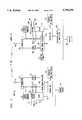
- FIG. 2 of the drawingthere is shown a general block diagram of certain circuitry of the cordless telephone base unit 10 and of the cordless telephone handset unit 20.
- handset units 30 and 40incorporate these same components and are operationally identical. Both base unit 10 and handset unit 20 are operable over a plurality of communication channels in a frequency hopping system.
- a control unit 110for providing synchronization to: 1) the control unit 110, 2) a time domain duplexer (TDD) 120 and 3) a combined digital-to-analog and analog-to-digital (D/A+A/D) converter 125.
- a radio frequency (RF) transceiver 130Also included in the base unit 10 is a radio frequency (RF) transceiver 130, a signal strength monitor circuit 135, an antenna 140 and a frequency synthesizer 150.
- RFradio frequency
- a telephone circuit 160 in the base unit 10connects this unit to a central office or other appropriate switch through tip and ring lines 101 and 102.
- An interface unit and display 165contains the switches and a visual display for configuring the base unit in its various modes for communicating with one of more of the handset units 20 through 40.
- the transceiver 130comprise both an RF transmitter and an RF receiver.
- the transceiver 130demodulates voice signals transmitted by the handset unit 20 and couples these signals via the D/A section of converter 125 to the telephone circuit 160.
- the transceiver 130also has as its input speech and other control signals from the telephone circuit 160 which are first coupled through the A/D section of converter 125 before being transmitted to the handset unit 20 by this transceiver 130.
- the telephone circuit 160serves as a "plain old telephone service" (POTS) interface for signals on the tip-ring lines 101 and 102 and for those signals received from the handset unit 20 by the RF transceiver 130.
- POTSplain old telephone service
- a power circuit 170provides operating power for all of the circuitry in the base unit 10.
- the control unit 110advantageously provides a number of control functions and may be implemented through the use of a microcomputer containing read-only-memory (ROM), random-access-memory (RAM) and through use of the proper coding.
- ROMread-only-memory
- RAMrandom-access-memory
- Such a microcomputeris known in the art and is readily available from semiconductor manufacturers such as Motorola, Signetics, Intel and AMD.
- a microcomputer available from Motorola as part number 6805C4is usable as control unit 110 with the proper programming.
- a time division duplexer suitable for use as TDD 120is available from AT&T Microelectronics as part number 1000DD.
- the control unit 110generates and stores security code data and also generates pseudo-random seeds from which pseudo-random data lists are generated. Assembly language code for generating such a list in the 6805C4 microcomputer is provided in Appendix 1. It is to be understood that random data lists also may be generated in a pseudo-random manner in accordance with the teaching of S. W. Golomb in Digital Communications With Space Applications (New Jersey: Prentice-Hall 1964) pp. 7-15.
- the first generated listis for the base unit 10 and has a group of 173 data values which correspond to a first set of 173 random channels.
- the second generated listis for handset unit 20 having a second group of 52 data values which correspond to a second set of 52 random channels.
- the third generated listis for handset unit 30 having a third group of 52 data values which correspond to a third set of 52 random channels.
- a fourth generated listis for handset unit 40 having a fourth group of 52 data values which correspond to a fourth set of 52 random channels. All channels are selected from 173 possible channels available in the 902-928 MHz frequency band.
- the first set of 173 random channelsis used by the base unit 10 for establishing communications with one of the three handset units. These channels are selected during a frequency hopping cycle executed in accordance with the Federal Communication Commission's General Docket No. 89-5354.
- the second, third and fourth sets of 52 random channelsare respectively used during a frequency hopping cycle executed by an associated handset also in accordance with the Federal Communication Commission's General Docket No. 89-354. Two of the 52 random channels, channels 51 and 52 selected for each handset, are used during an initialization process described in detail later herein.
- the control unit 110also generates yet another set of data values from a random number seed.
- This set of data valuestypically 10, corresponds to a set of 10 random channels. These channels also are part of the 173 channels available in the 902-928 MHz frequency band. If interference is detected by the base unit or the handset unit with which it is communicating on any one of the second, third or fourth set of channels in a frequency hopping cycle, the affected unit initiates a channel change process whereby one or more channels are selected from this group of random channels for substitution for the channel or channels in the second, third or fourth set of channels upon which the interference was detected.
- the control unit of the handset unit serving as the base unittakes on the role of generating this extra set of data values and communicating a data value to the handset unit with which it is communicating when a channel substitution becomes necessary, because of, for example, detected interference on a channel.
- the control unit 110controls and configures the TDD 120.
- the pseudo-randomly generated data list from the control unit 110is provided to the TDD where it is stored therein.
- the TDD 120controls the frequencies selected in the frequency hopping cycle of the base unit 10 by inputting into the frequency synthesizer 150 at the appropriate time the values stored in the data list generated by the control unit 110.
- the TDD 120also refreshes the frequency synthesizer 150 as the synthesizer progresses though the frequency hopping cycle.
- the signal strength monitor circuit 135continually monitors the strength of the received signal from the handset unit 20 during ongoing communications with the handset unit 20.
- This signal strength monitor circuit 135may be, for example, a received signal strength indicator (RSSI) circuit.
- RSSIreceived signal strength indicator
- the control unit 110regulates the amount of power transmitted by the transmitter in the RF transceiver 130 to the handset unit 20.
- the level of power radiated by the RF transceiver 130is reduced to a minimum acceptable level.
- the level of power radiated by RF transceiver 130is increased to its maximum permitted level.
- components in this unitinclude a control unit 210, a wake-up timer 212 and a clock 215 for providing synchronization to: 1) the control unit 210, 2) a time domain duplexer (TDD) 220 and 3) a combined digital-to-analog and analog-to-digital (D/A+A/D) converter 225.
- a control unit 210for providing synchronization to: 1) the control unit 210, 2) a time domain duplexer (TDD) 220 and 3) a combined digital-to-analog and analog-to-digital (D/A+A/D) converter 225.
- TDDtime domain duplexer
- D/A+A/Ddigital-to-digital converter
- An interface unit and display 265contains switches and a visual display for configuring the handset unit 20 in an appropriate mode for communicating with the base unit 10.
- a battery 270provides operating power for all the circuitry in the handset unit 20. This battery is charged by the power circuit 170 via a charge contact interface (not shown) formed when the handset unit 20 is placed in a mating cradle of either the base unit 10 or an auxiliary base unit cradle which has no communication capability.
- a charge contact interface usable between base unit 10 and handset unit 20is described in U.S. Pat. No. 5,323,447 which issued to M. E. Gillis et al. on Jun. 21, 1994.
- handset units 30 and 40contain the same components that are in handset unit 20 and are operationally identical.
- the transceiver 230comprises both an RF transmitter and an RF receiver.
- This transceiver 230demodulates voice signals transmitted by the base unit 10 and couples these signals via the D/A section of converter 225, a hybrid 283, and an amplifier 285 on to a loudspeaker 281.
- the transceiver 230also has as its input analog speech signals from a microphone 282 which it transmits to the base unit 10. These analog speech signals are coupled to the transceiver via an amplifier 284, the hybrid 283 and the A/D section of converter 225. This converter converts the analog signal to a digital signal which is then provided to the RF transceiver 230.
- the signal strength monitor 235monitors the received signal level from the base unit 10 and accordingly varies the level of the output power radiated by the RF transceiver 230 in proportion to this received signal level.
- any communications between the base unit 10 and the handset unit 20must be accompanied by a security code then shared between them.
- the control unit 210must be able to make a favorable comparison of the received security code data with its stored security code data.
- a favorable comparison of the data from the two security codesalso must be made by control unit 110 in order for the base unit 10 to respond to a call set-up request from a handset unit.
- the control unit 210may be implemented through the use of a microcomputer containing ROM, RAM and through use of the proper coding.
- a microcomputeris known in the art and is readily available from semiconductor manufacturers such as Motorola, Signetics, Intel and AMD.
- a microcomputer available from Motorola as part number 6805C4is usable as control unit 210.
- a time division duplexer suitable for use as TDD 220is available from AT&T Microelectronics as part number 1000DD.
- the handset unit 20While the handset unit 20 is not being used for communications and is located remote from the base unit 10, the handset unit 20 enters a low power monitoring mode which includes powering down and then powering up certain minimum circuitry in the handset unit 20 as necessary for satisfactory operation.
- the control unit 210turns itself off or puts itself to sleep and signals the TDD 220 also to turn off while in the powered down state.
- the TDD 220activates wake-up timer 212, which comprises, for example a one-shot-monostable-multivibrator, and turns off all other clock-driven circuitry in the handset unit 20.
- the handset unit 20is powered up into a minimum power operating state for 40 milliseconds.
- This change of stateis initiated by a pulse provided to the TDD 220 from wake-up timer 212 at the end of the 360 milliseconds.
- the TDD 220is enabled thereby and, in turn, turns on the control unit 210, the clock 215 and the receiver portion of the transceiver 230 for determining if an RF signal is being transmitted from the base unit 10 or if a key has been pushed on the keypad in the interface unit and display 265. If neither of these has occurred, the control unit 210 again turns off power to itself and to the TDD 220, and the cycle is repeated.
- This low power monitoring modecontinues as long as an RF signal is not received from the base unit 10 or a key has not been pushed on the keypad.
- this signalis coupled to the control unit 210 which looks for an initialization synchronization (sync) pattern in the signal within the 40 milliseconds that the handset unit is powered up to its minimum power operating state. If the received initialization sync pattern does not contain the security code that is recognized by the handset unit, the control unit 210 turns off power to itself and to the TDD 220. If the initialization sync pattern does contains the security code that is recognized by the handset unit, however, the control unit 210 causes the low power monitoring mode to be overridden. In so doing, the control unit 210 continues to enable the TDD 220 beyond its normal ON time in order to establish synchronization with the RF signal being received from the base unit.
- initialization synchronizationsync
- the low power monitoring mode of the handset unit 20also is overridden by certain key pushes on the keypad. Once certain keys are pushed, the handset unit 20 is configured in the full ON operate state (the transmitter and receiver in the RF transceiver 230 both turn on) and attempts to establish synchronism with the base unit 10 by transmitting an RF signal to this unit.
- thisis the process that configures the handset units 20 through 40 for communicating with the base unit 10 or the handset units for communicating with each other.
- Each of the handset units 20 through 40must be provided with a security code from the base unit 10 during the registration process in order for subsequent radio frequency communications to take place between the base unit and a handset or between handsets.
- the handset unit and the base unitare both shipped from the factory in a default mode wherein a common default security code and a default channel are employed by both of these units. Also while in this mode, the transmitted power level from both the base unit and the handset unit are reduced to and provided at a low power level below the normal operating power level.
- the userinstalls a battery in the handset and cradles the handset unit in the base unit for charging this battery. After the battery has been charged for a suitable time, the user removes the handset unit and goes off-hook either in the phone or the intercom mode.
- the cordless telephoneWhen the user goes off-hook at the handset unit, the cordless telephone recognizes that it is in the default mode and automatically transfers both the security code data and the starting channel data from the base unit to the handset unit, while operating at the low power level.
- the security code datais generated in the base unit in accordance with the teachings of U.S. Pat. No. 4,736,404 which issued to R. E. Anglikowski et al. on Apr. 5, 1988.
- the starting channel datais a pseudo-random number seed. This seed, used for generating the starting channel and also random subsequent channels, is generated by the control unit in the base unit in accordance with the assembly language code provided in Appendix 1.
- the handset unitautomatically acknowledges to the base unit when it has received the security code data and the starting channel data. Once this data has been received and acknowledged, both the base unit and the handset unit begin frequency hopping in the manner described in U.S. Pat. No. 5,353,341 which issued to M. E. Gillis et al. on Oct. 4, 1994.
- the transmitted power levelis returned to the normal operating power level from the low power level. If subsequent reregistration of the base unit and the handset unit becomes necessary, because of, for example, either the base unit or the handset unit becoming inoperative and having to be replaced, the user may execute the registration process described next herein with reference to FIG. 3, and stop the registration process when only the one handset unit has been registered.
- FIG. 3there is shown the protocol of the cordless telephone depicting the specific processes executed by both the base unit 10 and the handsets 20 through 40 in performing the registration process.
- the registration process for multiple handset unitsrequires the user to activate a sequence of buttons in the user interface and display 265, shown in FIG. 2, at each handset unit after initiating the registration state at the base unit 10.
- the base unit 10transfers common security code data, and also a pseudo-random seed assigned to each handset unit that is registered, to all of the multiple handset units that are registered in the system.
- the protocolbegins at step 301 where registration is initiated at the base unit 10 by actuating a dedicated registration switch which is a part of the interface unit and display 165, shown in FIG. 2.
- This switchis typically located on the rear of the base unit 10 and is protected from inadvertent activation by either recessing, providing a protective collar around the switch, or other similar measures. Instructions on the registration procedure are easily provided either in a pull-out drawer on the bottom of the base unit 10 or on a stick-on label affixed to the base unit.
- the base unit and all handset units in the cordless telephonemust be in a standby state (i.e., no phone call or intercom call is being initiated or in progress).
- the base unit and all handset unitsgo to a predetermined registration communication channel where the handset units are then configured for specific operation with the base unit.
- This registration communication channelis typically selected at the time of manufacture so that subsequently manufactured and purchased handset units for use within a system will be easily configurable by a user.
- a userpresses and holds the registration switch or button at the base as in step 301 (for about two seconds) until a burst of tone sounds indicating that the base unit is ready to register handset units.
- Both PHONE and INTERCOM light emitting diodes (LEDs) in the interface unit and display 165 on the base unitflash in synchrony as in step 302 as long as the base unit is in the registration state.
- the cordless telephone stationi.e., both the base unit and handset unit
- the cordless telephone stationis operating at a low power level below the normal operating power level and no calls can be placed or received from this station.
- step 303the process advances to step 303.
- the userpresses a number button in the dial pad on the base unit which is indicative of a number "N" of handset units that the user then wishes to register.
- the base unitis then informed of how many different pseudo-random number seeds it needs to generate. A different seed is used by the base unit and by each one of the plurality of handset units in generating a starting channel for each one of these units. The base unit is then able to transmit not only its number seed to each handset unit so that these handset units knows which channel to monitor, but also is able to transmit to each handset unit the number seed of each of the other handset units to facilitate these handset units communicating with each other, as explained in detail later herein.
- step 303the process advances to decision 304.
- a usermust press the # button on a handset unit he or she then wishes to register with the base unit 10. If no action is taken, either at the base unit or at the handset unit within, for example, 15 seconds after the base enters the registration state, the registration state will time out, the base unit returns to the idle state, and the handset units currently in use with the base will remain unaffected.
- the userAfter initiating the registration process and configuring the base unit 10 in the registration state, the user proceeds to register the multiple handset units. Although only three handset units are shown and described, as indicated earlier herein, a greater or lesser number may also be registered in accordance with the principles of this invention and such variation is anticipated.
- the userpresses the # button on the dialpad to prepare the handset unit to enter registration with the base unit.
- PHONE and INTERCOM LEDs in the handset unitflash at the same rate as the base unit LEDs to indicate that the handset unit is on the registration communication channel and ready for registration.
- the userpresses the PHONE button on the handset unit to establish a communications link with the base unit and also a number key such as the 1 button (represented by handset number 20, for example) on the dialpad to register the handset unit address.
- the handset unitthen gives a "happy tone” and the PHONE and INTERCOM LEDs go off to confirm that this handset unit has been successfully registered.
- the usermay continue to register the remainder of the handset units by pressing #, PHONE, 2, for handset 30; by pressing #, PHONE, N, for the last handset N, for example, as depicted in decisions 312 through 315.
- Each handset unitgives a happy tone as it is successfully registered. If a handset unit is not successfully registered, however, a sad tone is provided at the handset unit, as depicted in decision 305 and step 317 and also decision 318 and step 319.
- the base unitremains in its registration state waiting for a valid keypress on any handset unit. If there is no valid keypress within 15 seconds, as in step 316, for example, the base unit also exits the registration state, retaining only successful handset unit registrations.
- any handset unit previously associated (or registered) with the base unitcontinues to work with the base unit until at least one handset unit is successfully registered during the new registration session.
- the flashing base unit LEDsare turned off, a distinct tone sounds at the base unit and the base returns to the idle state.
- the registration stateis exited when one of the following occurs: 1) the user has registered the indicated number "N" of handset units; 2) the user presses the registration button on the base unit (toggles off); 3) the user presses the OFF button on the handset unit; and 4) there is no valid button press during registration for, by way of example, 15 seconds.
- the handset unitshave non-volatile memory so that handset registration is not lost when a battery is depleted or during a battery swap.
- each handset unitbegins to monitor the broadcast channel of the base unit for a signal from either the base unit or any other handset unit attempting to establish communications with another handset unit over this channel.
- the base unitbegins to sequentially monitor each one of the channels respectively assigned to the handset units for detecting a signal from a handset unit attempting to establish communications with the base unit.
- any one of the system handset unitswhen multiple handset units are registered with a base unit, any one of the system handset units will have the ability to selectively page and use the intercom with another system handset unit or the base unit.
- Such a communications radio-linkis illustrated in FIG. 5 which shows handset unit 30 communicating with handset unit 20.
- any one of the handset unitsis able to send a general or broadcast page signal which will be received by each one of the other handset units in the system.
- FIG. 4there is shown the protocol of the cordless telephone system where a first handset unit is able to page a second handset unit and the second handset unit is able to directly answer the intercom call from the first handset unit.
- each of the three illustrated registered handset unitsis given an address of either 1, 2, or 3 (handset 1, handset 2, or handset 3, for example).
- This assigned addressallows a user to selectively page a designated handset unit in the system by pressing the INTCM button followed by the handset address. While the designated handset unit is being signaled, the signaled handset unit can answer by opening the intercom to the initiating handset unit.
- the protocolis entered at step 401 where a user at handset 1 may, for example, want to send a page signal to handset 2.
- the user at handset 1presses the INTCM button and then 2 on the dialpad of handset 1, as shown in decision 402. This sends a page signal to handset 2 via step 403 and flashes the INTCM LEDs at both handset 1 and 2 for X seconds, where X is typically 15 seconds.
- the INTCM buttonis pressed at handset 2 during the interval that the LED is flashing, the intercom connection is opened between handset 1 and handset 2 (the initiating handset unit and the paged handset unit) as shown in step 405.
- the INTCM buttonis not pressed at the signaled handset unit (i.e., the paged handset unit does not answer), the INTCM LEDs at both handset units go off when the interval times out and the handset units return to the standby state.
- the initiating handset unitcan also abort the intercom request as in step 406 by pressing the OFF button. If a user at another (third) handset unit presses the INTCM button while a handset unit is being paged, or after an intercom connection is already established, that handset unit will get a four-beep busy tone and will be locked out from the intercom.
- a handset unitcan also open the intercom to the base unit 10 by addressing the base unit in the same way that a handset unit is addressed. This protocol is shown in steps 410, 412 and 414, and decisions 411 and 413.
- the base unitalways has an address of 0 (zero).
- a userpresses the INTCM button and then 0 on the dialpad. If a user at a handset unit presses the INTCM button and does not key in an address within X seconds, where X is typically 15, the default is to open the intercom between the handset unit and the base unit.
- the INTCM LEDs at the initiating handset unit and the base unitwill in this instance go on.
- any subsequent press of the INTCM button at the handset unitwill send a page signal to the base unit.
- the base unitpages the handset units by providing a broadcast page to all registered handset units when the PAGE button is pressed at the base unit.
- the page signalis sent to all handset units and flashes the INTCM LEDs at the base unit and the handset units for X seconds, where X is typically 15.
- Any handset unitcan answer the page signal and open the intercom connection to the base by pressing the INTCM button while the INTCM LED on the handset unit is flashing.
- the INTCM LEDs on the handset unit and the base unitgo on steady. If another handset unit presses the INTCM button after the connection has already been established, that handset unit gets a four-beep busy tone and is locked out from the intercom.
- the INTCM buttonis not pressed at any of the signaled handset units (i.e., no handset unit answers the page), the INTCM LEDs at the base unit and the handset units go off when the interval times out and the handset units all return to the standby state.
- a telephone call received on one handset unitmay be transferred to another handset unit registered with the base unit. Because only one handset unit can be on a call with the base unit at a time, the radio communication link between the answering handset unit and the base unit must be released before another handset unit can establish the link and pick up the held call. Whenever the radio communication link between the base unit and a handset unit is released, the base unit returns to monitoring those channels used for respectively initiating communications from the handset units to the base unit. A button on the handset unit allows the user to place the call in a suspended state and release the link so that another handset unit can connect to the call by pressing the PHONE button.
- the original handset unitis also able to reestablish the link and reconnect to the suspended call by pressing the PHONE button in the event that another handset unit does not pick up the call.
- the phone LEDs on other handset unitsare configured to blink for indicating that the telephone line is in use.
- Communications between the base unit 10 and the handset unit 20occur in time periods designated as transmission frames.
- the base unit and the handset unitboth transmit to each other.
- a typical transmission framemay be, for example, 5 milliseconds in length and contain time slots for approximately 500 bits of information.
- the base unitgenerally transmits in the first half of each frame or for 2.5 milliseconds and is then reconfigured to receive a signal from the handset unit which transmits in the second half of each frame or for 2.5 milliseconds on the same frequency.
- the handset unitoperates in complementary fashion to the base unit in that it receives in the first half of each frame and is reconfigured to transmit in the second half of each frame.
- This cyclic frame transmissiongenerates 80 frames in approximately 400 milliseconds with the base unit and handset unit both hopping to and transmitting and receiving on each of the 50 communication channels.
- Channel 51is the channel used for initiating communications from the handset unit to the base unit.
- Channel 0zero is the channel used for initiating communications from the base unit to the handset unit.
- Each handset unithas its own assigned channel 51 provided to it by the base unit at registration, as described later herein.
- the base unitsends the initialization synchronization pattern on channel 0 for 400 milliseconds.
- the handset unitalso sends this same initialization synchronization pattern but on channel 51 in time periods equal to the second part of each frame for 120 milliseconds.
- This synchronization patterncomprises a dotting sequence signal, followed by a security code, a barker code and a period in which no information is transmitted as discussed later herein.
- the dotting sequence signalis a series of ones and zeros that are provided for enabling the handset unit 20, and also the base unit 10, to align the phase of its receive clock with the phase of the clock providing the incoming signal. When the phase of these clocks is aligned, the handset unit is then able to read in the proper bit boundary the security code and barker code that follow the dotting sequence signal.
- the base unitWhen attempting to contact the handset unit, the base unit sends 198 bits of the dotting sequence signal followed by the security code.
- This security codeis a 16-bits random number generated by the base unit and, as earlier indicated, is transferred to the control unit 210 in the handset unit 20 over a low power radio-link during the registration process which registers the multiple handset units used in the system.
- This shared security codeguards against another base unit inadvertently synchronizing with the handset units that are registered with the system.
- the security codeis followed in the initialization synchronization pattern by the barker code.
- This barker codeis a fixed predetermined eight-bit pattern which provides a position reference in a frame for aligning a frame clock of the receiver in the handset unit with the frame clock of the transmitter in the base unit. This permits the handset unit 20 to reestablish frame sync or frame phase with the base unit 10 after the handset unit has been turned off during its low power monitoring mode of operation.
- a frame clock in the receiver of the base unit 10must similarly be aligned with a frame clock of the transmitter in the handset unit.
- the base unit 10After the base unit 10 transmits the security code and barker code in the initialization sync pattern, no additional information is sent by the base unit in each frame for a time period equal to 30 bits. A delay is provided in this time period for certain internal processing to occur, including, for example, the reconfiguring of the frequency synthesizer 150 for receiving the initialization sync pattern from the handset unit 20.
- FIG. 6there is shown the timing diagram for illustrating the operation of the base unit 10 in the cordless telephone system in providing an initializing signal for establishing communications with either one of the handset units 20, 30 or 40.
- a handset unitmay similarly operate in the manner of the base unit and also generate an initializing signal.
- An initialization sync pattern from the base unit 10is transmitted in frame position 600. This initializing sync pattern is a broadcast signal and provides a means for the base unit to activate the handset units to a full ON operating condition from the minimum power operating state.
- the base unitWhen there is an incoming call or a press of the page button on the base unit, the base unit begins transmitting a dotting pattern on its communication channel 0 in frame position 600 for 400 milliseconds.
- the pseudo-random number seed for this channel 0is provided to each of the handset units during the registration procedure. Each handset unit therefore monitors this channel to detect any attempts by the base unit to establish communications.
- the basesends the initialization sync pattern on channel 0 in frame position 600, each handset unit within the reception range of this base unit wakes up or cycles to the on state and moves on to channel 1 which is shown in frame position 610.
- the handset unitsSince the handset units have the seed for channel 0, they are thus able to move with the base unit to its subsequent channels, for example, channels 1, 2 and 3, in the frequency hopping cycle until communication between a handset unit and the base unit is established.
- the base unit and the handset unitsall use the same algorithm to generate the list of communication channels used in each of the frequency hopping cycles.
- the receiver in transceiver 130 in base unit 10is configured to listen on the starting or set-up channel for each handset unit in position 611 for approximately 35 milliseconds each.
- the receivershifts from listening for dotting on the starting channel 51 assigned to handset 20, to listening for dotting on the starting channel 51 assigned to handset 30 to finally listening for dotting on the starting channel 51 assigned to handset 40.
- the transmitter in transceiver 130is configured for transmitting the dotting or initialization sync pattern in the frame position 615. This time for this signal is approximately 85 milliseconds.
- the opcode messagefor example ring or page
- the base unitmoves on to channel 2.
- the processing steps executed on channel 1are again executed on channel 2.
- the base unitmoves on to channel 3, and subsequent channels, repeating the same steps until it has moved among all 173 channels. Then the process starts again and continues until a handset unit respond or the ringing signal or paging signal is discontinued.
- Each of the subsequent channelsare identical to channel 1 in that the base unit first listens on the set-up channels for each handset unit, send the initialization sync pattern and then send the opcode message on the channel.
- these additional channelsare also selected from the seed of channel 0 with each proceeding channel being the basis for selecting the subsequent channel.
- This generation techniqueis equivalent to a listing of 173 channels with each channel always appearing at the same position in the list.
- a person at a handset unitIn order to get a response on one of the set-up channels from a handset unit, a person at a handset unit must go off-hook in responding to the ring or page signal. Otherwise the base unit does not receive a signal from a handset unit. Once the base unit receives a dotting signal from either one of the handset units, it attempts to establish communications just with that handset unit on its set-up channel and stops sending the dotting signal on its broadcast channel.
- control unit 110are advantageously determined by a process or program stored in read only memory (not shown).
- the processis entered at step 701 where the base unit transmitter is idle and its receiver is monitoring each set-up channel, channel 51, for each one of the handset units. Once a ring is detected or page button is pressed on the base unit, the process advances to step 703 where the base unit sends a dotting signal for 400 milliseconds. In step 704 the base unit 10 moves to channel 1.
- the handset unitWhile on channel 1, the handset unit loads the handset's set-up channels for each of the handset units in steps 705, 706 and 707 while looking for dotting on each of these channels. If a sync pattern is detected on one of the handset unit channels, the process advances to a synchronization processing routine shown as step 709 and described in detail later herein with reference to FIG. 8.
- the base unitsends dotting to the handset units in step 710 and a ring or page message in step 711.
- the base unitmoves to channel 2 in step 712 and the processing steps in steps 713, 714, 715, 718, 719 and decision 716 are executed, these steps and the decision being essentially a repeat of the steps and decision executed for channel 1. If no response from a handset unit is received while the base unit is on channel 2, the process repeats the steps and decisions in channels 3 to 173.
- Handset unitsmay advantageously be configured to communicate with other handset units, in accordance with the disclosed embodiment.
- a first handset unitfor example, handset unit 20 can have its circuitry, i.e., its TDD 220 reconfigured such that this circuit will cause the handset unit 20 to transmit and receive in the same manner as the base unit 10.
- handset unit 20attempts to communicate with, for example, handset unit 30, handset unit 20 will send on channel 0 a dotting signal for 400 milliseconds during which all handset units wake-up and go to channel 1.
- the handset unit 20moves to channel 1, like the base unit 10 illustrated in frame position 610, a number of processing steps in this handset unit are performed.
- the handset unit 20Since the handset unit 20 is attempting to communicate with handset unit 30, the handset unit 20 sends a selective page opcode message to handset unit 30 and only listens to the set-up channel designated for this handset unit. In this regard it is different from the base unit 10 which sends a broadcast page opcode message and listens to each one of the set-up channels for each handset unit. Otherwise the processing steps in the handset unit for this frame position is identical to that of the base unit where an initialization sync pattern and the opcode message are also sent on this and any necessary subsequent channels.
- the hopping list that they useis generated from the channel that was used to synchronize on by these handset units.
- handset unit 20 and handset unit 30use the set-up channel and communication channels assigned to handset unit 30. These communication channels are loaded into both TDD circuits in these handset units and accessed at the 5 MS hopping rate.
- one of the 50 channels loaded into the TDDis found to be unusable due to interference, etc., it is replaced with the next channel generated from a pseudo-random seed, as earlier described herein or generated by the pseudo-random generator as described in U.S. Pat. No. 5,323,447 which issued to M. E. Gillis et al. on Jun. 21, 1994.
- the initial handset unitIn order to communication with another handset unit, the initial handset unit must discontinue the communications link it has with the base unit.
- the user presses a transfer key on the handset unitwhich activates a message transmission from the handset unit to the base telling the base to disengage the communication link, but keep the off-hook relay open.
- a press of the phone button on any of the handset unitswould cause any of the handset units to go off-hook and be connected to the call.
- the userat this time, is able to page another handset unit to tell the person at that handset unit that there is a call on the telephone line.
- the paged personis then able to press his or her phone button and his or her handset unit establishes synchronism with the base unit and connects this handset unit to the telephone line.
- the usermay need to page a person at one of the other handset units.
- the usernext presses the intercom button and the handset unit is configured in the manner of the base unit as described earlier herein for contacting a selected one of the other handset units.
- the base unitmay then also communicate with the remaining free handset unit. Since handset units communicating with each other move away from the broadcast channels once a telecommunication link has been established between them, the base unit and the remaining handset unit may advantageously then use the broadcast channels to establish another communication link between itself and the remaining free handset unit.
- control unit 110is advantageously determined by a process or program stored in read only memory (not shown).
- the processis entered at step 801 where the base unit transmitter is turned on and the initialization sync pattern is transmitted on channel 51 for 400 milliseconds. From step 801, the process advances to step 802 wherein the base transceiver (transmitter and receiver) is tuned to channel 52. The transmitter again transmits the initialization sync pattern on this channel and the receiver begins to monitor this channel for receipt of the initialization sync pattern expected to be provided by the handset unit on this channel.
- step 803the process advances to step 803 where a 400 millisecond timer is started.
- decision 804a determination is made as to whether the handset unit is sending the initialization sync pattern as expected on channel 52. If this sync pattern is not being received, the process advances to the decision 805 where a determination is made as to whether the 400 millisecond timer has expired. If this timer has expired, the attempt to establish communications with the handset unit is terminated and the process returns to the step 701 in FIG. 7 where it again monitors channel 51. If the timer has not expired in decision 805, the process returns to decision 804 and continue to look for the initialization sync pattern on channel 52. If in decision 804, it is found that the handset unit is sending its initialization sync pattern on channel 52, the process advances to decision 806.
- the processadvances to step 808 where the base unit stops sending its initialization sync pattern, sends a message to the handset unit to cause it to also stop sending its sync pattern. The base unit also sends the hop message to the handset unit in this step and begins its countdown to the time at which the frequency hopping sequence is to start. Once the countdown sequence ends, the call setup routine is exited and the process enters the base hop routine.
Landscapes
- Engineering & Computer Science (AREA)
- Computer Networks & Wireless Communication (AREA)
- Signal Processing (AREA)
- Mobile Radio Communication Systems (AREA)
- Transceivers (AREA)
Abstract
Description
APPENDIX ONE ______________________________________ GEN.sub.-- LIST Generate a maximal length pseudorandom list of channels. ______________________________________ * PORT * bits * ram * rand.sub.-- num,ran.sub.-- seed * equates * MSK equ $b8 get.sub.-- seed 1da ACLR Gather 8 bits. sta ran.sub.-- seed Start at one. rts gen.sub.-- list 1da ran.sub.-- speed ; brclr 0, ran.sub.-- seed,gen.sub.-- 1.sub.-- 1 1sra eor #MSK bra gen.sub.-- 1.sub.-- 2 gen.sub.-- 1.sub.-- 1 1sra gen.sub.-- 1.sub.-- 2 sta ran.sub.-- seed sta rand.sub.-- num gen.sub.-- 1.sub.-- 3 1da rand.sub.-- num cmp #MAX.sub.-- FREQ bhi gen.sub.-- list ; Branch if Acca.> memory. OK rts ______________________________________
Claims (12)
Priority Applications (1)
| Application Number | Priority Date | Filing Date | Title |
|---|---|---|---|
| US08/652,196US5758290A (en) | 1994-07-05 | 1996-05-23 | Cordless telephone arranged for operating with multiple portable units in a frequency hopping system |
Applications Claiming Priority (3)
| Application Number | Priority Date | Filing Date | Title |
|---|---|---|---|
| US27034894A | 1994-07-05 | 1994-07-05 | |
| US08/333,705US5809417A (en) | 1994-07-05 | 1994-11-03 | Cordless telephone arranged for operating with multiple portable units in a frequency hopping system |
| US08/652,196US5758290A (en) | 1994-07-05 | 1996-05-23 | Cordless telephone arranged for operating with multiple portable units in a frequency hopping system |
Related Parent Applications (1)
| Application Number | Title | Priority Date | Filing Date |
|---|---|---|---|
| US08/333,705ContinuationUS5809417A (en) | 1994-07-05 | 1994-11-03 | Cordless telephone arranged for operating with multiple portable units in a frequency hopping system |
Publications (1)
| Publication Number | Publication Date |
|---|---|
| US5758290Atrue US5758290A (en) | 1998-05-26 |
Family
ID=23303928
Family Applications (2)
| Application Number | Title | Priority Date | Filing Date |
|---|---|---|---|
| US08/333,705Expired - LifetimeUS5809417A (en) | 1994-07-05 | 1994-11-03 | Cordless telephone arranged for operating with multiple portable units in a frequency hopping system |
| US08/652,196Expired - LifetimeUS5758290A (en) | 1994-07-05 | 1996-05-23 | Cordless telephone arranged for operating with multiple portable units in a frequency hopping system |
Family Applications Before (1)
| Application Number | Title | Priority Date | Filing Date |
|---|---|---|---|
| US08/333,705Expired - LifetimeUS5809417A (en) | 1994-07-05 | 1994-11-03 | Cordless telephone arranged for operating with multiple portable units in a frequency hopping system |
Country Status (6)
| Country | Link |
|---|---|
| US (2) | US5809417A (en) |
| EP (1) | EP0711057A3 (en) |
| JP (1) | JP3194569B2 (en) |
| KR (1) | KR100304176B1 (en) |
| CA (1) | CA2160283C (en) |
| TW (1) | TW299945U (en) |
Cited By (54)
| Publication number | Priority date | Publication date | Assignee | Title |
|---|---|---|---|---|
| US6052407A (en)* | 1997-10-01 | 2000-04-18 | Lucent Technologies Inc. | Apparatus and method for detection frequency hopping patterns embedded in radio frequency noise |
| US6091758A (en)* | 1997-10-01 | 2000-07-18 | Lucent Technologies Inc. | Cordless telephone arranged for operating with multiple portable units in a frequency hopping system |
| US6115408A (en)* | 1998-04-03 | 2000-09-05 | Butterfly Vsli Ltd. | Automatic transmission power level control method in a frequency hopping communication system |
| US6115407A (en)* | 1998-04-03 | 2000-09-05 | Butterfly Vsli Ltd. | Frequency hopping communication method and apparatus for modifying frequency hopping sequence in accordance with counted errors |
| US6151352A (en)* | 1996-04-16 | 2000-11-21 | Brother Kogyo Kabushiki Kaisha | Wireless communication using a frequency hopping method |
| US6263210B1 (en)* | 1995-05-18 | 2001-07-17 | Canon Kabushiki Kaisha | Wireless communication system and method of controlling same |
| US6298218B1 (en) | 1996-12-18 | 2001-10-02 | Clubcom, Inc. | Combined advertising and entertainment system network |
| US6466800B1 (en)* | 1999-11-19 | 2002-10-15 | Siemens Information And Communication Mobile, Llc | Method and system for a wireless communication system incorporating channel selection algorithm for 2.4 GHz direct sequence spread spectrum cordless telephone system |
| US6487390B1 (en) | 1996-12-18 | 2002-11-26 | Clubcom, Inc. | System and method for interactive on-demand information |
| US6498935B1 (en)* | 1999-04-19 | 2002-12-24 | Agere Systems Inc. | Channel selection and clarity improvement for digital cordless telephones operating in an overlapped range |
| US6604138B1 (en) | 1996-12-18 | 2003-08-05 | Clubcom, Inc. | System and method for providing demographically targeted information |
| US6792263B1 (en)* | 1997-10-03 | 2004-09-14 | Karen Jeanne Kite | Remote operational screener |
| US7299060B1 (en) | 2002-12-10 | 2007-11-20 | Sprint Spectrum L.P. | Method and system for wireless bridging |
| US20080233987A1 (en)* | 2007-03-23 | 2008-09-25 | Brother Kogyo Kabushiki Kaisha | Communication apparatus |
| US20080281171A1 (en)* | 2007-05-08 | 2008-11-13 | Abbott Diabetes Care, Inc. | Analyte monitoring system and methods |
| US20100076284A1 (en)* | 2007-06-21 | 2010-03-25 | Abbott Diabetes Care Inc. | Health Management Devices and Methods |
| US20100274220A1 (en)* | 2005-11-04 | 2010-10-28 | Abbott Diabetes Care Inc. | Method and System for Providing Basal Profile Modification in Analyte Monitoring and Management Systems |
| US20110044333A1 (en)* | 2008-05-30 | 2011-02-24 | Abbott Diabetes Care Inc. | Close Proximity Communication Device and Methods |
| US20110060530A1 (en)* | 2009-08-31 | 2011-03-10 | Abbott Diabetes Care Inc. | Analyte Signal Processing Device and Methods |
| US8259775B1 (en) | 2008-10-17 | 2012-09-04 | Honeywell International, Inc. | System, apparatus and method for managing message communications in systems employing frequency hopping |
| US8362904B2 (en) | 2007-05-08 | 2013-01-29 | Abbott Diabetes Care Inc. | Analyte monitoring system and methods |
| US8385384B1 (en) | 2008-10-17 | 2013-02-26 | Honeywell International Inc. | System, method and apparatus for selecting frequency hopping sequences |
| US8437966B2 (en) | 2003-04-04 | 2013-05-07 | Abbott Diabetes Care Inc. | Method and system for transferring analyte test data |
| US8456301B2 (en) | 2007-05-08 | 2013-06-04 | Abbott Diabetes Care Inc. | Analyte monitoring system and methods |
| US8461985B2 (en) | 2007-05-08 | 2013-06-11 | Abbott Diabetes Care Inc. | Analyte monitoring system and methods |
| US8553743B1 (en) | 2008-10-17 | 2013-10-08 | Honeywell International Inc. | System, apparatus and method for communicating messages using multiple frequency hopping sequences |
| US8593109B2 (en) | 2006-03-31 | 2013-11-26 | Abbott Diabetes Care Inc. | Method and system for powering an electronic device |
| US8597575B2 (en) | 2006-03-31 | 2013-12-03 | Abbott Diabetes Care Inc. | Analyte monitoring devices and methods therefor |
| US8617069B2 (en) | 2007-06-21 | 2013-12-31 | Abbott Diabetes Care Inc. | Health monitor |
| US8677342B1 (en) | 2008-10-17 | 2014-03-18 | Honeywell International Inc. | System, method and apparatus for replacing wireless devices in a system |
| US8771183B2 (en) | 2004-02-17 | 2014-07-08 | Abbott Diabetes Care Inc. | Method and system for providing data communication in continuous glucose monitoring and management system |
| US8891586B1 (en) | 2008-10-17 | 2014-11-18 | Honeywell International Inc. | System, apparatus and method for identifying transmission frequencies for communicating data |
| US8993331B2 (en) | 2009-08-31 | 2015-03-31 | Abbott Diabetes Care Inc. | Analyte monitoring system and methods for managing power and noise |
| US9069536B2 (en) | 2011-10-31 | 2015-06-30 | Abbott Diabetes Care Inc. | Electronic devices having integrated reset systems and methods thereof |
| US9088452B2 (en) | 2009-04-29 | 2015-07-21 | Abbott Diabetes Care Inc. | Method and system for providing data communication in continuous glucose monitoring and management system |
| US9095290B2 (en) | 2007-03-01 | 2015-08-04 | Abbott Diabetes Care Inc. | Method and apparatus for providing rolling data in communication systems |
| US9210125B1 (en) | 2008-10-17 | 2015-12-08 | Honeywell International Inc. | System, method and apparatus for binding communication devices through common association |
| US9226701B2 (en) | 2009-04-28 | 2016-01-05 | Abbott Diabetes Care Inc. | Error detection in critical repeating data in a wireless sensor system |
| US9532737B2 (en) | 2011-02-28 | 2017-01-03 | Abbott Diabetes Care Inc. | Devices, systems, and methods associated with analyte monitoring devices and devices incorporating the same |
| US9574914B2 (en) | 2007-05-08 | 2017-02-21 | Abbott Diabetes Care Inc. | Method and device for determining elapsed sensor life |
| US9735831B1 (en) | 2009-09-22 | 2017-08-15 | Honeywell International Inc. | System, apparatus and method for synchronizing communications between devices |
| US9730584B2 (en) | 2003-06-10 | 2017-08-15 | Abbott Diabetes Care Inc. | Glucose measuring device for use in personal area network |
| US9962091B2 (en) | 2002-12-31 | 2018-05-08 | Abbott Diabetes Care Inc. | Continuous glucose monitoring system and methods of use |
| US9968306B2 (en) | 2012-09-17 | 2018-05-15 | Abbott Diabetes Care Inc. | Methods and apparatuses for providing adverse condition notification with enhanced wireless communication range in analyte monitoring systems |
| US9980669B2 (en) | 2011-11-07 | 2018-05-29 | Abbott Diabetes Care Inc. | Analyte monitoring device and methods |
| US10022499B2 (en) | 2007-02-15 | 2018-07-17 | Abbott Diabetes Care Inc. | Device and method for automatic data acquisition and/or detection |
| US10136816B2 (en) | 2009-08-31 | 2018-11-27 | Abbott Diabetes Care Inc. | Medical devices and methods |
| US20190139391A1 (en)* | 2017-11-03 | 2019-05-09 | Institute For Information Industry | Safety status sensing system and safety status sensing method thereof |
| US10320442B1 (en) | 2018-02-09 | 2019-06-11 | Ademco Inc. | High bandwidth channel in a frequency hopping system |
| US11006872B2 (en) | 2009-02-03 | 2021-05-18 | Abbott Diabetes Care Inc. | Analyte sensor and apparatus for insertion of the sensor |
| US11793936B2 (en) | 2009-05-29 | 2023-10-24 | Abbott Diabetes Care Inc. | Medical device antenna systems having external antenna configurations |
| US12239463B2 (en) | 2020-08-31 | 2025-03-04 | Abbott Diabetes Care Inc. | Systems, devices, and methods for analyte sensor insertion |
| US12268496B2 (en) | 2017-01-23 | 2025-04-08 | Abbott Diabetes Care Inc. | Systems, devices and methods for analyte sensor insertion |
| US12274548B2 (en) | 2006-10-23 | 2025-04-15 | Abbott Diabetes Care Inc. | Sensor insertion devices and methods of use |
Families Citing this family (26)
| Publication number | Priority date | Publication date | Assignee | Title |
|---|---|---|---|---|
| JP3752724B2 (en)* | 1996-04-16 | 2006-03-08 | ブラザー工業株式会社 | Wireless communication system |
| DE19615563C2 (en)* | 1996-04-19 | 1998-07-23 | Nokia Mobile Phones Ltd | Method for operating a telecommunications system and telecommunications system in which the method can be used |
| US6389057B1 (en)* | 1996-12-23 | 2002-05-14 | Telefonaktiebolaget Lm Ericsson (Publ) | Access technique of channel hopping communications system |
| US6128504A (en)* | 1997-10-01 | 2000-10-03 | Lucent Technologies Inc. | Apparatus and method of contention resolution for a plurality of handset units in a cordless telephone system |
| US6278722B1 (en)* | 1998-02-25 | 2001-08-21 | Lucent Technologies Inc. | Architecture for a digital portable telephone |
| EP0955780A1 (en)* | 1998-04-17 | 1999-11-10 | Alcatel | Wireless communication system, base station and mobile subscriber terminal, exchanging radio signals according to a sequence of frequency hoppings |
| US6098100A (en)* | 1998-06-08 | 2000-08-01 | Silicon Integrated Systems Corp. | Method and apparatus for detecting a wake packet issued by a network device to a sleeping node |
| US6484027B1 (en)* | 1998-06-15 | 2002-11-19 | Sbc Technology Resources, Inc. | Enhanced wireless handset, including direct handset-to-handset communication mode |
| FR2781960A1 (en)* | 1998-07-28 | 2000-02-04 | Canon Kk | Procedure for communication over wireless telephone or computer, fax etc. network, involves station which provides guide signal, switching into base station mode from mobile station mode, in absence of base station |
| FR2781954B1 (en)* | 1998-07-28 | 2000-11-03 | Canon Kk | COMMUNICATION METHOD AND DEVICE ON A NETWORK |
| EP1653708B1 (en)* | 1998-07-28 | 2011-10-05 | Canon Kabushiki Kaisha | Method and device for communication on a network |
| FR2781953A1 (en)* | 1998-07-28 | 2000-02-04 | Canon Kk | Network communication system |
| DE69940685D1 (en) | 1998-07-28 | 2009-05-20 | Canon Kk | Method and device for message transmission in a network |
| US6396825B1 (en)* | 1998-08-18 | 2002-05-28 | Motorola, Inc. | Method and apparatus for using a pseudo-random signal in a communication system |
| US6434394B1 (en)* | 1998-10-02 | 2002-08-13 | Lucent Technologies Inc. | Multiple handset cordless telephone including a ring signal/call routing module |
| US6473613B2 (en)* | 1998-12-18 | 2002-10-29 | Conexant Systems, Inc. | Method and system for generating a secure wireless link between a handset and base station |
| US6349213B1 (en)* | 1999-06-14 | 2002-02-19 | Agere Systems Guardian Corp. | Apparatus for enhanced voice quality in multiple cordless handset environment and method |
| US6327300B1 (en)* | 1999-10-25 | 2001-12-04 | Motorola, Inc. | Method and apparatus for dynamic spectrum allocation |
| US6845242B1 (en)* | 1999-11-04 | 2005-01-18 | Mci, Inc. | Cordless telephone system |
| KR100380518B1 (en)* | 2001-05-24 | 2003-04-18 | 한국전자통신연구원 | Secure codeless phone having the bluetooth |
| US7218738B2 (en) | 2002-01-02 | 2007-05-15 | Sony Corporation | Encryption and content control in a digital broadcast system |
| US6980770B1 (en) | 2002-07-26 | 2005-12-27 | Uniden America Corporation | Mobile marine communications apparatus |
| US8248989B2 (en)* | 2008-11-05 | 2012-08-21 | Electronics And Telecommunications Research Institute | Wireless network system using cyclic frame |
| TWI413409B (en)* | 2008-11-06 | 2013-10-21 | Ind Tech Res Inst | Method for determining and changing radio frequency channel and radio frequency transmitting/receiving system using the same |
| CN101753225B (en)* | 2008-12-03 | 2013-12-18 | 财团法人工业技术研究院 | Radio Frequency Channel Determination and Change Method and Radio Frequency Wireless Transceiving System |
| JP2012199599A (en)* | 2009-08-06 | 2012-10-18 | Panasonic Corp | Cordless phone |
Citations (14)
| Publication number | Priority date | Publication date | Assignee | Title |
|---|---|---|---|---|
| US3810019A (en)* | 1972-09-25 | 1974-05-07 | Sperry Rand Corp | Multifrequency communication system for fading channels |
| US4677617A (en)* | 1985-10-04 | 1987-06-30 | Hughes Aircraft Company | Rapid frequency-hopping time synchronization |
| US4829540A (en)* | 1986-05-27 | 1989-05-09 | Fairchild Weston Systems, Inc. | Secure communication system for multiple remote units |
| US4998290A (en)* | 1988-05-09 | 1991-03-05 | Canadian Marconi Corporation | Frequency-hopping radio communication network |
| US5014295A (en)* | 1988-10-28 | 1991-05-07 | Sony Corporation | Multi-channel access cordless telephone system |
| US5044010A (en)* | 1990-03-29 | 1991-08-27 | At&T Bell Laboratories | Arrangement and method for selecting an available communication channel for a cordless telephone |
| US5237603A (en)* | 1989-12-11 | 1993-08-17 | Sony Corporation | Cordless telephone which intermittently monitors predetermined channels from all available channels |
| US5243641A (en)* | 1990-08-01 | 1993-09-07 | At&T Bell Laboratories | Extended range cordless telephone system |
| US5263176A (en)* | 1990-02-08 | 1993-11-16 | Nec Corporation | Method of assigning optimal channel in multi-station radio communications system |
| US5353341A (en)* | 1991-10-21 | 1994-10-04 | At&T Bell Laboratories | Cordless telephone arranged for operation in a frequency hopping system |
| US5363428A (en)* | 1991-05-17 | 1994-11-08 | Nec Corporation | Dynamic channel assignment cordless telecommunication network |
| US5418839A (en)* | 1990-04-13 | 1995-05-23 | Phonemate, Inc. | Environmental adaptive mechanism for channel utilization in cordless telephones |
| US5463659A (en)* | 1994-07-05 | 1995-10-31 | At&T Ipm Corp. | Apparatus and method of configuring a cordless telephone for operating in a frequency hopping system |
| US5568510A (en)* | 1994-09-27 | 1996-10-22 | At&T Ipm Corp. | Apparatus and method for obtaining synchronism between a base station and a portable unit arranged for operation in a frequency hopping system |
Family Cites Families (14)
| Publication number | Priority date | Publication date | Assignee | Title |
|---|---|---|---|---|
| US4231114A (en)* | 1978-02-27 | 1980-10-28 | Motorola, Inc. | Synchronizing means for a two-way communication system |
| IN159180B (en)* | 1982-01-27 | 1987-04-04 | Marconi Co Ltd | |
| FR2527871B1 (en)* | 1982-05-27 | 1986-04-11 | Thomson Csf | RADIOCOMMUNICATION SYSTEM, FREQUENCY HOPPING |
| JPS61105138A (en)* | 1984-10-29 | 1986-05-23 | Nec Corp | Radiotelephone equipment |
| US4802200A (en)* | 1985-08-27 | 1989-01-31 | Nippon Telegraph And Telephone Corporation | Radio telephone system control apparatus and method |
| US4850036A (en)* | 1987-08-21 | 1989-07-18 | American Telephone And Telegraph Company | Radio communication system using synchronous frequency hopping transmissions |
| US5133002A (en)* | 1989-07-28 | 1992-07-21 | Ascii Corporation | Radiotelephone system that maintains synchronization between base and subordinate units while shifting carrier frequencies |
| JP3093243B2 (en)* | 1990-07-12 | 2000-10-03 | 株式会社東芝 | Mobile radio communication system |
| NZ239283A (en)* | 1990-08-23 | 1994-09-27 | Ericsson Telefon Ab L M | Mobile cellular radio: handoff between half rate and full rate channels according to estimated received signal quality |
| US5307370A (en)* | 1991-06-03 | 1994-04-26 | Motorola, Inc. | Secure cordless radio-telephone |
| US5323447A (en)* | 1991-11-01 | 1994-06-21 | At&T Bell Laboratories | Apparatus and method for modifying a frequency hopping sequence of a cordless telephone operating in a frequency hopping system |
| US5247702A (en)* | 1991-11-08 | 1993-09-21 | Teknekron Communications Systems, Inc. | Method and an apparatus for establishing a wireless communication link between a base unit and a remote unit |
| JPH05276098A (en)* | 1992-03-30 | 1993-10-22 | Casio Comput Co Ltd | Cordless phone base unit |
| US5325420A (en)* | 1992-09-30 | 1994-06-28 | Fujitsu Limited | Cordless phone haaving a plurality of personal stations |
- 1994
- 1994-11-03USUS08/333,705patent/US5809417A/ennot_activeExpired - Lifetime
- 1995
- 1995-05-20TWTW085210553Upatent/TW299945U/enunknown
- 1995-10-11CACA002160283Apatent/CA2160283C/ennot_activeExpired - Fee Related
- 1995-10-24EPEP95307536Apatent/EP0711057A3/ennot_activeWithdrawn
- 1995-11-02JPJP28545895Apatent/JP3194569B2/ennot_activeExpired - Fee Related
- 1995-11-03KRKR1019950039521Apatent/KR100304176B1/ennot_activeExpired - Fee Related
- 1996
- 1996-05-23USUS08/652,196patent/US5758290A/ennot_activeExpired - Lifetime
Patent Citations (14)
| Publication number | Priority date | Publication date | Assignee | Title |
|---|---|---|---|---|
| US3810019A (en)* | 1972-09-25 | 1974-05-07 | Sperry Rand Corp | Multifrequency communication system for fading channels |
| US4677617A (en)* | 1985-10-04 | 1987-06-30 | Hughes Aircraft Company | Rapid frequency-hopping time synchronization |
| US4829540A (en)* | 1986-05-27 | 1989-05-09 | Fairchild Weston Systems, Inc. | Secure communication system for multiple remote units |
| US4998290A (en)* | 1988-05-09 | 1991-03-05 | Canadian Marconi Corporation | Frequency-hopping radio communication network |
| US5014295A (en)* | 1988-10-28 | 1991-05-07 | Sony Corporation | Multi-channel access cordless telephone system |
| US5237603A (en)* | 1989-12-11 | 1993-08-17 | Sony Corporation | Cordless telephone which intermittently monitors predetermined channels from all available channels |
| US5263176A (en)* | 1990-02-08 | 1993-11-16 | Nec Corporation | Method of assigning optimal channel in multi-station radio communications system |
| US5044010A (en)* | 1990-03-29 | 1991-08-27 | At&T Bell Laboratories | Arrangement and method for selecting an available communication channel for a cordless telephone |
| US5418839A (en)* | 1990-04-13 | 1995-05-23 | Phonemate, Inc. | Environmental adaptive mechanism for channel utilization in cordless telephones |
| US5243641A (en)* | 1990-08-01 | 1993-09-07 | At&T Bell Laboratories | Extended range cordless telephone system |
| US5363428A (en)* | 1991-05-17 | 1994-11-08 | Nec Corporation | Dynamic channel assignment cordless telecommunication network |
| US5353341A (en)* | 1991-10-21 | 1994-10-04 | At&T Bell Laboratories | Cordless telephone arranged for operation in a frequency hopping system |
| US5463659A (en)* | 1994-07-05 | 1995-10-31 | At&T Ipm Corp. | Apparatus and method of configuring a cordless telephone for operating in a frequency hopping system |
| US5568510A (en)* | 1994-09-27 | 1996-10-22 | At&T Ipm Corp. | Apparatus and method for obtaining synchronism between a base station and a portable unit arranged for operation in a frequency hopping system |
Cited By (128)
| Publication number | Priority date | Publication date | Assignee | Title |
|---|---|---|---|---|
| US6263210B1 (en)* | 1995-05-18 | 2001-07-17 | Canon Kabushiki Kaisha | Wireless communication system and method of controlling same |
| US20050041632A1 (en)* | 1995-05-18 | 2005-02-24 | Takumi Takahashi | Wireless communication system and method of controlling same |
| US6804289B2 (en) | 1995-05-18 | 2004-10-12 | Canon Kabushiki Kaisha | Wireless communication system and method of controlling same |
| US7099370B2 (en) | 1995-05-18 | 2006-08-29 | Canon Kabushiki Kaisha | Wireless communication system and method of controlling same |
| US6151352A (en)* | 1996-04-16 | 2000-11-21 | Brother Kogyo Kabushiki Kaisha | Wireless communication using a frequency hopping method |
| US6487390B1 (en) | 1996-12-18 | 2002-11-26 | Clubcom, Inc. | System and method for interactive on-demand information |
| US6298218B1 (en) | 1996-12-18 | 2001-10-02 | Clubcom, Inc. | Combined advertising and entertainment system network |
| US6604138B1 (en) | 1996-12-18 | 2003-08-05 | Clubcom, Inc. | System and method for providing demographically targeted information |
| US6671736B2 (en) | 1996-12-18 | 2003-12-30 | Clubcom, Inc. | System and method for providing demographically targeted information |
| US20040229568A1 (en)* | 1996-12-18 | 2004-11-18 | Lowe Danny D. | Combined advertising and entertainment system network |
| US7058412B2 (en) | 1996-12-18 | 2006-06-06 | Clubcom, Inc | Combined advertising and entertainment system network |
| US6052407A (en)* | 1997-10-01 | 2000-04-18 | Lucent Technologies Inc. | Apparatus and method for detection frequency hopping patterns embedded in radio frequency noise |
| US6091758A (en)* | 1997-10-01 | 2000-07-18 | Lucent Technologies Inc. | Cordless telephone arranged for operating with multiple portable units in a frequency hopping system |
| US6792263B1 (en)* | 1997-10-03 | 2004-09-14 | Karen Jeanne Kite | Remote operational screener |
| US6115407A (en)* | 1998-04-03 | 2000-09-05 | Butterfly Vsli Ltd. | Frequency hopping communication method and apparatus for modifying frequency hopping sequence in accordance with counted errors |
| US6115408A (en)* | 1998-04-03 | 2000-09-05 | Butterfly Vsli Ltd. | Automatic transmission power level control method in a frequency hopping communication system |
| US6498935B1 (en)* | 1999-04-19 | 2002-12-24 | Agere Systems Inc. | Channel selection and clarity improvement for digital cordless telephones operating in an overlapped range |
| US6466800B1 (en)* | 1999-11-19 | 2002-10-15 | Siemens Information And Communication Mobile, Llc | Method and system for a wireless communication system incorporating channel selection algorithm for 2.4 GHz direct sequence spread spectrum cordless telephone system |
| US7299060B1 (en) | 2002-12-10 | 2007-11-20 | Sprint Spectrum L.P. | Method and system for wireless bridging |
| US7907917B1 (en) | 2002-12-10 | 2011-03-15 | Sprint Spectrum L.P. | Method and system for wireless bridging |
| US10750952B2 (en) | 2002-12-31 | 2020-08-25 | Abbott Diabetes Care Inc. | Continuous glucose monitoring system and methods of use |
| US10039881B2 (en) | 2002-12-31 | 2018-08-07 | Abbott Diabetes Care Inc. | Method and system for providing data communication in continuous glucose monitoring and management system |
| US9962091B2 (en) | 2002-12-31 | 2018-05-08 | Abbott Diabetes Care Inc. | Continuous glucose monitoring system and methods of use |
| US8682598B2 (en) | 2003-04-04 | 2014-03-25 | Abbott Laboratories | Method and system for transferring analyte test data |
| US8560250B2 (en) | 2003-04-04 | 2013-10-15 | Abbott Laboratories | Method and system for transferring analyte test data |
| US8437966B2 (en) | 2003-04-04 | 2013-05-07 | Abbott Diabetes Care Inc. | Method and system for transferring analyte test data |
| US8483974B2 (en) | 2003-04-04 | 2013-07-09 | Abbott Diabetes Care Inc. | Method and system for transferring analyte test data |
| US9730584B2 (en) | 2003-06-10 | 2017-08-15 | Abbott Diabetes Care Inc. | Glucose measuring device for use in personal area network |
| US8771183B2 (en) | 2004-02-17 | 2014-07-08 | Abbott Diabetes Care Inc. | Method and system for providing data communication in continuous glucose monitoring and management system |
| US20100274220A1 (en)* | 2005-11-04 | 2010-10-28 | Abbott Diabetes Care Inc. | Method and System for Providing Basal Profile Modification in Analyte Monitoring and Management Systems |
| US9323898B2 (en) | 2005-11-04 | 2016-04-26 | Abbott Diabetes Care Inc. | Method and system for providing basal profile modification in analyte monitoring and management systems |
| US9669162B2 (en) | 2005-11-04 | 2017-06-06 | Abbott Diabetes Care Inc. | Method and system for providing basal profile modification in analyte monitoring and management systems |
| US8585591B2 (en) | 2005-11-04 | 2013-11-19 | Abbott Diabetes Care Inc. | Method and system for providing basal profile modification in analyte monitoring and management systems |
| US11538580B2 (en) | 2005-11-04 | 2022-12-27 | Abbott Diabetes Care Inc. | Method and system for providing basal profile modification in analyte monitoring and management systems |
| US9625413B2 (en) | 2006-03-31 | 2017-04-18 | Abbott Diabetes Care Inc. | Analyte monitoring devices and methods therefor |
| US9743863B2 (en) | 2006-03-31 | 2017-08-29 | Abbott Diabetes Care Inc. | Method and system for powering an electronic device |
| US8593109B2 (en) | 2006-03-31 | 2013-11-26 | Abbott Diabetes Care Inc. | Method and system for powering an electronic device |
| US8597575B2 (en) | 2006-03-31 | 2013-12-03 | Abbott Diabetes Care Inc. | Analyte monitoring devices and methods therefor |
| US8933664B2 (en) | 2006-03-31 | 2015-01-13 | Abbott Diabetes Care Inc. | Method and system for powering an electronic device |
| US9380971B2 (en) | 2006-03-31 | 2016-07-05 | Abbott Diabetes Care Inc. | Method and system for powering an electronic device |
| US9039975B2 (en) | 2006-03-31 | 2015-05-26 | Abbott Diabetes Care Inc. | Analyte monitoring devices and methods therefor |
| US12274548B2 (en) | 2006-10-23 | 2025-04-15 | Abbott Diabetes Care Inc. | Sensor insertion devices and methods of use |
| US10617823B2 (en) | 2007-02-15 | 2020-04-14 | Abbott Diabetes Care Inc. | Device and method for automatic data acquisition and/or detection |
| US10022499B2 (en) | 2007-02-15 | 2018-07-17 | Abbott Diabetes Care Inc. | Device and method for automatic data acquisition and/or detection |
| US9801545B2 (en) | 2007-03-01 | 2017-10-31 | Abbott Diabetes Care Inc. | Method and apparatus for providing rolling data in communication systems |
| US9095290B2 (en) | 2007-03-01 | 2015-08-04 | Abbott Diabetes Care Inc. | Method and apparatus for providing rolling data in communication systems |
| US20080233987A1 (en)* | 2007-03-23 | 2008-09-25 | Brother Kogyo Kabushiki Kaisha | Communication apparatus |
| US10653317B2 (en) | 2007-05-08 | 2020-05-19 | Abbott Diabetes Care Inc. | Analyte monitoring system and methods |
| US9574914B2 (en) | 2007-05-08 | 2017-02-21 | Abbott Diabetes Care Inc. | Method and device for determining elapsed sensor life |
| US12396645B2 (en) | 2007-05-08 | 2025-08-26 | Abbott Diabetes Care Inc. | Analyte monitoring system and methods |
| US9000929B2 (en) | 2007-05-08 | 2015-04-07 | Abbott Diabetes Care Inc. | Analyte monitoring system and methods |
| US9035767B2 (en) | 2007-05-08 | 2015-05-19 | Abbott Diabetes Care Inc. | Analyte monitoring system and methods |
| US12357180B2 (en) | 2007-05-08 | 2025-07-15 | Abbott Diabetes Care Inc. | Analyte monitoring system and methods |
| US20080281171A1 (en)* | 2007-05-08 | 2008-11-13 | Abbott Diabetes Care, Inc. | Analyte monitoring system and methods |
| US11696684B2 (en) | 2007-05-08 | 2023-07-11 | Abbott Diabetes Care Inc. | Analyte monitoring system and methods |
| US10952611B2 (en) | 2007-05-08 | 2021-03-23 | Abbott Diabetes Care Inc. | Analyte monitoring system and methods |
| US9177456B2 (en) | 2007-05-08 | 2015-11-03 | Abbott Diabetes Care Inc. | Analyte monitoring system and methods |
| US10178954B2 (en) | 2007-05-08 | 2019-01-15 | Abbott Diabetes Care Inc. | Analyte monitoring system and methods |
| US8362904B2 (en) | 2007-05-08 | 2013-01-29 | Abbott Diabetes Care Inc. | Analyte monitoring system and methods |
| US8456301B2 (en) | 2007-05-08 | 2013-06-04 | Abbott Diabetes Care Inc. | Analyte monitoring system and methods |
| US9314198B2 (en) | 2007-05-08 | 2016-04-19 | Abbott Diabetes Care Inc. | Analyte monitoring system and methods |
| US9949678B2 (en) | 2007-05-08 | 2018-04-24 | Abbott Diabetes Care Inc. | Method and device for determining elapsed sensor life |
| US8461985B2 (en) | 2007-05-08 | 2013-06-11 | Abbott Diabetes Care Inc. | Analyte monitoring system and methods |
| US8593287B2 (en) | 2007-05-08 | 2013-11-26 | Abbott Diabetes Care Inc. | Analyte monitoring system and methods |
| US9649057B2 (en) | 2007-05-08 | 2017-05-16 | Abbott Diabetes Care Inc. | Analyte monitoring system and methods |
| US11276492B2 (en) | 2007-06-21 | 2022-03-15 | Abbott Diabetes Care Inc. | Health management devices and methods |
| US20100076284A1 (en)* | 2007-06-21 | 2010-03-25 | Abbott Diabetes Care Inc. | Health Management Devices and Methods |
| US8597188B2 (en) | 2007-06-21 | 2013-12-03 | Abbott Diabetes Care Inc. | Health management devices and methods |
| US11264133B2 (en) | 2007-06-21 | 2022-03-01 | Abbott Diabetes Care Inc. | Health management devices and methods |
| US8617069B2 (en) | 2007-06-21 | 2013-12-31 | Abbott Diabetes Care Inc. | Health monitor |
| US11770210B2 (en) | 2008-05-30 | 2023-09-26 | Abbott Diabetes Care Inc. | Close proximity communication device and methods |
| US8737259B2 (en) | 2008-05-30 | 2014-05-27 | Abbott Diabetes Care Inc. | Close proximity communication device and methods |
| US12368529B2 (en) | 2008-05-30 | 2025-07-22 | Abbott Diabetes Care Inc. | Close proximity communication device and methods |
| US8509107B2 (en) | 2008-05-30 | 2013-08-13 | Abbott Diabetes Care Inc. | Close proximity communication device and methods |
| US9184875B2 (en) | 2008-05-30 | 2015-11-10 | Abbott Diabetes Care, Inc. | Close proximity communication device and methods |
| US9831985B2 (en) | 2008-05-30 | 2017-11-28 | Abbott Diabetes Care Inc. | Close proximity communication device and methods |
| US20110044333A1 (en)* | 2008-05-30 | 2011-02-24 | Abbott Diabetes Care Inc. | Close Proximity Communication Device and Methods |
| US8259775B1 (en) | 2008-10-17 | 2012-09-04 | Honeywell International, Inc. | System, apparatus and method for managing message communications in systems employing frequency hopping |
| US9210125B1 (en) | 2008-10-17 | 2015-12-08 | Honeywell International Inc. | System, method and apparatus for binding communication devices through common association |
| US8861566B2 (en) | 2008-10-17 | 2014-10-14 | Honeywell International Inc. | System, apparatus and method for managing message communications in systems employing frequency hopping |
| US8553743B1 (en) | 2008-10-17 | 2013-10-08 | Honeywell International Inc. | System, apparatus and method for communicating messages using multiple frequency hopping sequences |
| US9979763B2 (en) | 2008-10-17 | 2018-05-22 | Honeywell International Inc. | System, method and apparatus for binding communication devices through common association |
| US8891586B1 (en) | 2008-10-17 | 2014-11-18 | Honeywell International Inc. | System, apparatus and method for identifying transmission frequencies for communicating data |
| US8385384B1 (en) | 2008-10-17 | 2013-02-26 | Honeywell International Inc. | System, method and apparatus for selecting frequency hopping sequences |
| US8677342B1 (en) | 2008-10-17 | 2014-03-18 | Honeywell International Inc. | System, method and apparatus for replacing wireless devices in a system |
| US10601882B2 (en) | 2008-10-17 | 2020-03-24 | Ademco Inc. | System, method and apparatus for binding communication devices through common association |
| US11166656B2 (en) | 2009-02-03 | 2021-11-09 | Abbott Diabetes Care Inc. | Analyte sensor and apparatus for insertion of the sensor |
| US11006872B2 (en) | 2009-02-03 | 2021-05-18 | Abbott Diabetes Care Inc. | Analyte sensor and apparatus for insertion of the sensor |
| US11202591B2 (en) | 2009-02-03 | 2021-12-21 | Abbott Diabetes Care Inc. | Analyte sensor and apparatus for insertion of the sensor |
| US11006870B2 (en) | 2009-02-03 | 2021-05-18 | Abbott Diabetes Care Inc. | Analyte sensor and apparatus for insertion of the sensor |
| US11006871B2 (en) | 2009-02-03 | 2021-05-18 | Abbott Diabetes Care Inc. | Analyte sensor and apparatus for insertion of the sensor |
| US11213229B2 (en) | 2009-02-03 | 2022-01-04 | Abbott Diabetes Care Inc. | Analyte sensor and apparatus for insertion of the sensor |
| US9226701B2 (en) | 2009-04-28 | 2016-01-05 | Abbott Diabetes Care Inc. | Error detection in critical repeating data in a wireless sensor system |
| US9693688B2 (en) | 2009-04-29 | 2017-07-04 | Abbott Diabetes Care Inc. | Method and system for providing data communication in continuous glucose monitoring and management system |
| US10172518B2 (en) | 2009-04-29 | 2019-01-08 | Abbott Diabetes Care Inc. | Method and system for providing data communication in continuous glucose monitoring and management system |
| US10617296B2 (en) | 2009-04-29 | 2020-04-14 | Abbott Diabetes Care Inc. | Method and system for providing data communication in continuous glucose monitoring and management system |
| US9088452B2 (en) | 2009-04-29 | 2015-07-21 | Abbott Diabetes Care Inc. | Method and system for providing data communication in continuous glucose monitoring and management system |
| US9949639B2 (en) | 2009-04-29 | 2018-04-24 | Abbott Diabetes Care Inc. | Method and system for providing data communication in continuous glucose monitoring and management system |
| US11793936B2 (en) | 2009-05-29 | 2023-10-24 | Abbott Diabetes Care Inc. | Medical device antenna systems having external antenna configurations |
| US11872370B2 (en) | 2009-05-29 | 2024-01-16 | Abbott Diabetes Care Inc. | Medical device antenna systems having external antenna configurations |
| US12364815B2 (en) | 2009-05-29 | 2025-07-22 | Abbott Diabetes Care Inc. | Medical device antenna systems having external antenna configurations |
| US9968302B2 (en) | 2009-08-31 | 2018-05-15 | Abbott Diabetes Care Inc. | Analyte signal processing device and methods |
| US11635332B2 (en) | 2009-08-31 | 2023-04-25 | Abbott Diabetes Care Inc. | Analyte monitoring system and methods for managing power and noise |
| US11150145B2 (en) | 2009-08-31 | 2021-10-19 | Abbott Diabetes Care Inc. | Analyte monitoring system and methods for managing power and noise |
| US20110060530A1 (en)* | 2009-08-31 | 2011-03-10 | Abbott Diabetes Care Inc. | Analyte Signal Processing Device and Methods |
| US12279894B2 (en) | 2009-08-31 | 2025-04-22 | Abbott Diabetes Care Inc. | Analyte signal processing device and methods |
| US10492685B2 (en) | 2009-08-31 | 2019-12-03 | Abbott Diabetes Care Inc. | Medical devices and methods |
| US10429250B2 (en) | 2009-08-31 | 2019-10-01 | Abbott Diabetes Care, Inc. | Analyte monitoring system and methods for managing power and noise |
| US8993331B2 (en) | 2009-08-31 | 2015-03-31 | Abbott Diabetes Care Inc. | Analyte monitoring system and methods for managing power and noise |
| USD1010133S1 (en) | 2009-08-31 | 2024-01-02 | Abbott Diabetes Care Inc. | Analyte sensor assembly |
| US9314195B2 (en) | 2009-08-31 | 2016-04-19 | Abbott Diabetes Care Inc. | Analyte signal processing device and methods |
| US11045147B2 (en) | 2009-08-31 | 2021-06-29 | Abbott Diabetes Care Inc. | Analyte signal processing device and methods |
| US10136816B2 (en) | 2009-08-31 | 2018-11-27 | Abbott Diabetes Care Inc. | Medical devices and methods |
| US12315630B2 (en) | 2009-08-31 | 2025-05-27 | Abbott Diabetes Care Inc. | Medical devices and methods |
| US9735831B1 (en) | 2009-09-22 | 2017-08-15 | Honeywell International Inc. | System, apparatus and method for synchronizing communications between devices |
| US10608698B2 (en) | 2009-09-22 | 2020-03-31 | Ademco Inc. | System, apparatus and method for synchronizing communications between devices |
| US9532737B2 (en) | 2011-02-28 | 2017-01-03 | Abbott Diabetes Care Inc. | Devices, systems, and methods associated with analyte monitoring devices and devices incorporating the same |
| US9069536B2 (en) | 2011-10-31 | 2015-06-30 | Abbott Diabetes Care Inc. | Electronic devices having integrated reset systems and methods thereof |
| US9465420B2 (en) | 2011-10-31 | 2016-10-11 | Abbott Diabetes Care Inc. | Electronic devices having integrated reset systems and methods thereof |
| US9980669B2 (en) | 2011-11-07 | 2018-05-29 | Abbott Diabetes Care Inc. | Analyte monitoring device and methods |
| US11950936B2 (en) | 2012-09-17 | 2024-04-09 | Abbott Diabetes Care Inc. | Methods and apparatuses for providing adverse condition notification with enhanced wireless communication range in analyte monitoring systems |
| US9968306B2 (en) | 2012-09-17 | 2018-05-15 | Abbott Diabetes Care Inc. | Methods and apparatuses for providing adverse condition notification with enhanced wireless communication range in analyte monitoring systems |
| US11612363B2 (en) | 2012-09-17 | 2023-03-28 | Abbott Diabetes Care Inc. | Methods and apparatuses for providing adverse condition notification with enhanced wireless communication range in analyte monitoring systems |
| US12419589B2 (en) | 2012-09-17 | 2025-09-23 | Abbott Diabetes Care Inc. | Methods and apparatuses for providing adverse condition notification with enhanced wireless communication range in analyte monitoring systems |
| US12268496B2 (en) | 2017-01-23 | 2025-04-08 | Abbott Diabetes Care Inc. | Systems, devices and methods for analyte sensor insertion |
| US20190139391A1 (en)* | 2017-11-03 | 2019-05-09 | Institute For Information Industry | Safety status sensing system and safety status sensing method thereof |
| US10320442B1 (en) | 2018-02-09 | 2019-06-11 | Ademco Inc. | High bandwidth channel in a frequency hopping system |
| US12239463B2 (en) | 2020-08-31 | 2025-03-04 | Abbott Diabetes Care Inc. | Systems, devices, and methods for analyte sensor insertion |
Also Published As
| Publication number | Publication date |
|---|---|
| JPH08265858A (en) | 1996-10-11 |
| EP0711057A3 (en) | 2000-08-30 |
| CA2160283A1 (en) | 1996-05-04 |
| KR960020042A (en) | 1996-06-17 |
| KR100304176B1 (en) | 2001-11-22 |
| US5809417A (en) | 1998-09-15 |
| EP0711057A2 (en) | 1996-05-08 |
| JP3194569B2 (en) | 2001-07-30 |
| CA2160283C (en) | 1999-07-20 |
| TW299945U (en) | 1997-03-01 |
Similar Documents
| Publication | Publication Date | Title |
|---|---|---|
| US5758290A (en) | Cordless telephone arranged for operating with multiple portable units in a frequency hopping system | |
| US5463659A (en) | Apparatus and method of configuring a cordless telephone for operating in a frequency hopping system | |
| KR100257173B1 (en) | Wireless telephone communication method and device | |
| US6091758A (en) | Cordless telephone arranged for operating with multiple portable units in a frequency hopping system | |
| US6128504A (en) | Apparatus and method of contention resolution for a plurality of handset units in a cordless telephone system | |
| US5323447A (en) | Apparatus and method for modifying a frequency hopping sequence of a cordless telephone operating in a frequency hopping system | |
| US5297203A (en) | Digital cordless telephone apparatus | |
| CA2157959C (en) | Apparatus and method for obtaining synchronism between a base station and a portable unit arranged for operation in a frequency hopping system | |
| US4905272A (en) | PABX cordless telephone system | |
| US5689549A (en) | Cordless telephone base unit arranged for operating with multiple portable units | |
| US6366572B1 (en) | Wireless communication system with symmetric communication protocol | |
| US6078819A (en) | Apparatus and method for prolonging battery life in a portable telephone having first and second deactivating conditions | |
| US6088595A (en) | Arrangement for configuring multiple portable units for communicating with each other in a frequency hopping system | |
| US6052407A (en) | Apparatus and method for detection frequency hopping patterns embedded in radio frequency noise | |
| CA2161723C (en) | Apparatus and method for synchronizing a cordless telephone base unit and multiple portable units on a common communication channel | |
| HK1005302A (en) | A cordless telephone arranged for operating with multiple portable units in a frequency hopping system | |
| HK1004250A (en) | An apparatus and method of configuring a cordless telephone for operating the same in a frequency hopping system communication system | |
| CA2155553C (en) | Cordless communications systems | |
| JPH0787166A (en) | Digital cordless phone | |
| GB2268370A (en) | Link quality monitoring in digital cordless telephone apparatus | |
| CA2151516C (en) | Method for continually monitoring the status of a radio frequency link | |
| JP3482726B2 (en) | Simple mobile phone |
Legal Events
| Date | Code | Title | Description |
|---|---|---|---|
| AS | Assignment | Owner name:LUCENT TECHNOLOGIES INC., NEW JERSEY Free format text:ASSIGNMENT OF ASSIGNORS INTEREST;ASSIGNORS:NEALONG, WILLIAM J.;RAJAN, HEIDI ANNE;REEL/FRAME:008202/0447;SIGNING DATES FROM 19960805 TO 19961004 | |
| FEPP | Fee payment procedure | Free format text:PAYOR NUMBER ASSIGNED (ORIGINAL EVENT CODE: ASPN); ENTITY STATUS OF PATENT OWNER: LARGE ENTITY | |
| STCF | Information on status: patent grant | Free format text:PATENTED CASE | |
| AS | Assignment | Owner name:THE CHASE MANHATTAN BANK, AS COLLATERAL AGENT, TEX Free format text:CONDITIONAL ASSIGNMENT OF AND SECURITY INTEREST IN PATENT RIGHTS;ASSIGNOR:LUCENT TECHNOLOGIES INC. (DE CORPORATION);REEL/FRAME:011722/0048 Effective date:20010222 | |
| FPAY | Fee payment | Year of fee payment:4 | |
| FPAY | Fee payment | Year of fee payment:8 | |
| AS | Assignment | Owner name:LUCENT TECHNOLOGIES INC., NEW JERSEY Free format text:TERMINATION AND RELEASE OF SECURITY INTEREST IN PATENT RIGHTS;ASSIGNOR:JPMORGAN CHASE BANK, N.A. (FORMERLY KNOWN AS THE CHASE MANHATTAN BANK), AS ADMINISTRATIVE AGENT;REEL/FRAME:018584/0446 Effective date:20061130 | |
| FPAY | Fee payment | Year of fee payment:12 | |
| AS | Assignment | Owner name:CREDIT SUISSE AG, NEW YORK Free format text:SECURITY INTEREST;ASSIGNOR:ALCATEL-LUCENT USA INC.;REEL/FRAME:030510/0627 Effective date:20130130 | |
| AS | Assignment | Owner name:ALCATEL-LUCENT USA INC., NEW JERSEY Free format text:RELEASE BY SECURED PARTY;ASSIGNOR:CREDIT SUISSE AG;REEL/FRAME:033950/0261 Effective date:20140819 |