US5758256A - Method of transporting speech information in a wireless cellular system - Google Patents
Method of transporting speech information in a wireless cellular systemDownload PDFInfo
- Publication number
- US5758256A US5758256AUS08/483,426US48342695AUS5758256AUS 5758256 AUS5758256 AUS 5758256AUS 48342695 AUS48342695 AUS 48342695AUS 5758256 AUS5758256 AUS 5758256A
- Authority
- US
- United States
- Prior art keywords
- base station
- origination
- destination
- port
- digital signals
- Prior art date
- Legal status (The legal status is an assumption and is not a legal conclusion. Google has not performed a legal analysis and makes no representation as to the accuracy of the status listed.)
- Expired - Fee Related
Links
Images


Classifications
- H—ELECTRICITY
- H04—ELECTRIC COMMUNICATION TECHNIQUE
- H04W—WIRELESS COMMUNICATION NETWORKS
- H04W88/00—Devices specially adapted for wireless communication networks, e.g. terminals, base stations or access point devices
- H04W88/18—Service support devices; Network management devices
- H04W88/181—Transcoding devices; Rate adaptation devices
- G—PHYSICS
- G10—MUSICAL INSTRUMENTS; ACOUSTICS
- G10L—SPEECH ANALYSIS TECHNIQUES OR SPEECH SYNTHESIS; SPEECH RECOGNITION; SPEECH OR VOICE PROCESSING TECHNIQUES; SPEECH OR AUDIO CODING OR DECODING
- G10L19/00—Speech or audio signals analysis-synthesis techniques for redundancy reduction, e.g. in vocoders; Coding or decoding of speech or audio signals, using source filter models or psychoacoustic analysis
- G10L19/012—Comfort noise or silence coding
Definitions
- Wireless cellular communication systemscarry voice signals and other information that are transmitted over a cellular network or the public switched telephone network (PSTN) and directed to various destinations.
- PSTNpublic switched telephone network
- a telephone handsetis used to convert speech into analog voice signals.
- the voice signalsare then processed in a fixed subscriber unit (FSU) so that they may be transmitted over a specific band of airwaves.
- the FSUcompresses the voice signals to maximize the number of conversations that may be carried over the airways.
- a wireless cellular systemalso has a base transceiver system (BTS) and a base station controller (BSC). These devices receive the signals transmitted by the FSU, and decompress the voice signals for transmission over the PSTN lines. The decompressed signals travel over the PSTN lines until they reach their predetermined destination. If the destination is a telephone connected to an FSU in another wireless cellular system, the voice signals are again compressed, then transmitted from the destination BSC to the destination FSU where they are decompressed yet another time. Each time a voice signal is compressed and decompressed, the voice signal is audibly degraded. Additionally, each time the voice signals are compressed and decompressed, the signals are delayed due to the processing required.
- BTSbase transceiver system
- BSCbase station controller
- voice signalsare taken through two compressions and two decompressions. This is done primarily because non-compatible telephones on the PSTN cannot understand compressed voice signals, so the compressed signal from the originating FSU must be decompressed before transmission on the PSTN. Also, even if the destination of the voice signal is a compatible FSU, the originating FSU has no way of knowing this.
- a method of transporting voice signalsis needed that will minimize voice signal degradation and delay, as well as recognize the type of destination to which a voice signal is sent.
- the present inventiongenerally relates to a method of transporting voice signals between wireless cellular systems such that the voice signals are only compressed and decompressed a single time. More specifically, the method involves first determining the compatibility of a destination port with the origination port of a voice signal. Next, a voice signal is provided at the origination port. The voice signal is then converted into a digital signal, and the origination subscriber unit port compresses the digital signal. After the voice signal is compressed, packets of the compressed digital signals are created and transmitted to the predetermined destination.
- the preferred single compression/decompression and packet transmission formatis initiated using useruser information channels to determine compatibility of the source and destination subscriber units.
- in-band signallingis used to determine compatibility of the source and destination subscriber units for the single compression/decompression and packet transmission format.
- the present inventionis capable of utilizing existing equipment in a fixed wireless cellular system to handle telephone calls from one FSU to another FSU, and from an FSU to a non-cellular destination, using only one compression/decompression step for calls to a compatible destination FSU. Accordingly, the present invention provides a method for compressing and decompressing a voice signal only one time, thereby reducing both the degradation of the voice signal and the delay caused by the second decompression/compression step. Additionally, the method can be performed on existing cellular communication equipment.
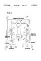
- FIG. 1illustrates a signal path of a voice signal transported over a wireless cellular system using a preferred embodiment of the present invention.
- FIG. 2is a diagram of a base station controller (BSC) for use in the wireless cellular system of FIG. 1.
- BSCbase station controller
- FIG. 3is a call flow chart of a voice signal transported according to a preferred embodiment of the present invention.
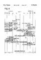
- FIG. 4is a call flow chart of a voice signal transported according to a second embodiment of the present invention.
- FIG. 5is a call flow chart of an unsuccessful FSU-to-FSU call using the method illustrated in FIG. 4.
- FIG. 6is a call flow chart detailing the failure response of a VAD STM in a destination BSC for the unsuccessful call of FIG. 5.
- FIG. 7is a call flow chart of a call originating from the PSTN.
- FIG. 1illustrates a voice signal being transported according to the method of the present invention.
- the source and destination for the telephone callare compatible cellular devices that may be fixed or portable.
- the voice signaloriginates at a telephone handset 5, typically an analog handset, and is transmitted to an origination port such as a fixed-subscriber unit (FSU) 10.
- the FSU 10which may be a multi-subscriber unit (MSU)
- MSUmulti-subscriber unit
- PCMpulse code modulated
- the wireless cellular systemutilizes mu-law or A-law PCM encoding formats commonly known in the art.
- the PCM signalis preferably compressed before transmission over cellular air wave frequencies.
- the PCM signalis preferably compressed to approximately 5 kilobits-per-second.
- the compressed signalis then transmitted from an antenna 11 connected to the FSU 10 along cellular frequencies to an antenna 12 connected to a base transceiver system (BTS) 15.
- the BTS 15is responsible for controlling the radio frequency (RF) cellular frequencies received from and transmitted to the FSU 10. After it receives the RF signal, the BTS 15 transports the compressed voice signal along a standard T1 line 17 to a base station controller (BSC) 20.
- BSC 20packetizes the compressed voice signal and then transports it along standard E1 transmission lines 24 to a switch 25 which directs the compressed signal to the proper destination BSC 30.
- the switchis preferably a mobile switching center (MSC) with user-user signalling capability.
- MSCmobile switching center
- the destination BSC 30depacketizes the compressed digital signal and transports it along standard T1 lines 17 to a destination BTS 35.
- the BTS 35then transmits the compressed signal from an antenna 3G connected to the BTS to an antenna 37 connected to the destination FSU 40 over a radio link using RF cellular frequencies.
- the destination FSU 40decompresses the compressed voice data back into an analog signal which is then sent to the telephone handset 45.
- the signal path 50 in FIG. 1pictorially represents the voice signal compression and decompression steps in a FSU 10 to FSU 40 call according to a preferred embodiment by showing a funnel shape where the signal is compressed or decompressed.
- the BTS to BSC connectionsare illustrated in FIG. 1 as T1 lines and the BSC to switch connections are shown as E1 lines, the connections may be either T1 or E1 lines. Additionally, cellular configurations other than shown in FIG. 1 may be used with a presently preferred embodiment of the invention.
- an FSU 10 to FSU 40 callrequired two compression and two decompression steps.
- the prior method of transporting speech informationinvolved a decompression step at the source BSC 20 and a compression step at the destination BSC 30 for outgoing calls and the reverse for incoming calls.
- the decompression/compression at the BSC 20, 30was in addition to the decompression/compression at the FSU 10, 40. So, rather than sending a compressed, packetized signal, the prior method was to decompress the voice signal to a 64 kilobits per second (kbps) digital PCM signal at the BSC 20, 30 for transmission on the E1 transmission lines 24.
- the single compression/decompression steps of the present methodmay be used if the PSTN 26 lines are capable of carrying uncorrupted digital information. Otherwise, calls between different but compatible cellular systems carried over the PSTN 26 must use the prior method of compression/decompression.
- FIG. 2is a block diagram of the different components of a BSC 20, 30.
- the BSC 20, 30includes a plurality of switching transcoder modules (STM) 21, at least one channel allocation processor (CAP) 22, and at least one call control processor (CCP) 23.
- STM 21, CAP 22, and CCP 23are circuit boards that preferably incorporate an Intel 960 32-bit RISC microprocessor.
- Each STM 21is connected to the T1 and E1 transmission lines 17, 24.
- the T1 and E1 transmission lines 17, 24can carry multiple channels of telephone calls.
- the CAPs 22assign specific STMs 21 to a particular channel corresponding to a particular call carried on the T1 and E1 lines 17, 24.
- the STMs 21may be interconnected with one or more CAPs 22. This interconnection is preferably through a VME standard data bus.
- the one or more CAPs 22are connected to one or more CCPs 23, preferably through an ethernet standard data bus.
- the STMs 21receive and transmit voice information data.
- the CAPs 22control connections to cellular airwaves and T1 transmission lines 17.
- the CCPs 23are responsible for telephone call control generally.
- a voice-activity-detector (VAD) STMdetermines when speech stops or starts.
- the VAD STMdetects speech signals received from the BSC 20, 30 or the BTS 15, 35.
- the traffic (TRF) STMcompresses or decompresses voice information and puts the compressed information in packets, or decodes the information from packets, depending upon whether it is receiving or transmitting the information.
- the packet data formattakes advantage of the extra space on the E1 lines 24 that is available when the voice information remains compressed in digital form.
- a comfort-noise-generation (CNG) STMtransmits only idle bits on the E1 transmission line 24 when no voice activity is detected by the VAD STM.
- a preferred comfort noise generation methodis disclosed in copending U.S. application Ser. No. 07/890,747, the entire disclosure of which is incorporated herein by reference.
- FIG. 3illustrates a call flow chart of a voice signal transported according to a preferred embodiment of the present invention.
- the compatibility of the destination BSC 30 with the source BSC 20is determined.
- the source BSC 20exchanges call setup information with the destination BSC 30.
- the call control processor (CCP) 23 assigned to the particular telephone call from the source BSCuses various call set-up messages (SETUP 52, ALERT 54 and CONNECT 56) which contain user-user data exchanged between the two base station controllers 20, 30.
- SETUP 52, ALERT 54 and CONNECT 56various call set-up messages which contain user-user data exchanged between the two base station controllers 20, 30.
- User-user informationis non-voice data allowed for in telecommunications standards and is carried in the set-up message slots provided for in the various standards.
- the call set-up messagesalso include user-user type messages that are exchanged between the BSC 20, 30 and the mobile switching center (MSC) 25 such as "Assign Request”, "Assign Complete”, and "Connect Ack” messages.
- MSCmobile switching center
- the set-up message format usedis the type defined in GSM recommendation 0.4.08, version 3.8.0, March 1990. While the GSM telecommunications standard is preferred, other standards capable of carrying user-user information may be used.
- the user-user datacontains information pertaining to the fixed subscriber unit (FSU) port connected to the BSC.
- the datacontain codec version, Digital Speech Interpolation (DSI) status, and call mode information.
- This exchange of user-user datainforms the origination port that the destination port is also a fixed wireless cellular communication port, that the lines between the FSUs are capable of transmitting digital data, and that there is compatible hardware and software to process the call at the destination port.
- the user-user informationis generated by, and interpreted in, the CCP 23 assigned to the call in each BSC 20, 30.
- the source BSC 20first begins a call by sending a SETUP message 52 containing user-user information which is received by the destination BSC 30.
- the SETUP message 52queries the destination BSC 30 about the source BSC 20.
- the mobile switching center (MSC) 25then informs the call control processor (CCP) 23 assigned to the call at both the source BSC 20 and the destination BSC 30 that a call is in progress.
- the MSC 25then sends a Channel Assign request to the CCP 23 at both the source and destination BSCs 20, 30.
- the CCP 23on either end of the call then communicates with the channel allocation processor (CAP) 22 to assign a channel to the call.
- the CAP 22then assigns the required number and type of switching transcoder modules (STM) 21 and communicates with the MSC 25 to inform the MSC 25 that the call assignments are completed.
- CAPchannel allocation processor
- the channel allocation process used in the base station controller 20, 30is preferably digital speech interpolation (DSI).
- DSIdigital speech interpolation
- a TRF STMis deallocated and a CNG STM transmits idle bytes on an E1 line 24
- thisis detected as voice inactivity by the VAD STM and reported to the CAP 22 which then deallocates both the RF air channel on the cellular channel and the T1 line 17 used in the call.
- the VAD STMdoes detect a speech spurt, this is also reported to the CAP 22, which then assigns an RF air channel and a T1 channel 17 to the appropriate FSU 10, 40 port, and the voice packet exchange resumes.
- Other channel allocation processes, aside from DSImay be used in the present invention.
- the CCP 23 of the destination BSC 30After setting up the channel assignments for the call at both ends, the CCP 23 of the destination BSC 30 sends an ALERT message 54 back to the CCP 23 of the source BSC 20.
- the ALERT message 54carries user-user information, responsive to the SETUP 52 query, informing the source BSC 20 as to whether or not the hardware and software at the destination BSC 30 are compatible for setting up a packet channel carrying compressed information.
- the MSC 25sends a ring back tone to a TRF STM.
- This ring back tonearrives at the origination port and sounds to the caller like a ring tone.
- the VAD STMdetects the activity and inactivity of the sound signal.
- a CONNECT message 56is sent from the CCP 23 of the destination BSC 30 to the CCP 23 of the source BSC 20. If the user-user information sent earlier shows a compatible FSU 40, then the packet channel compression begins.
- Both the source BSC 20 and the destination BSC 30assign a VAD STM and a CNG STM to handle the telephone call.
- the initialization of the packet channel formatstarts after a "Connect ACK" message is sent to the destination BSC 30.
- the CNG STMgenerates an idle pattern on the E1 transmission channel 24.
- the STMsends a "packet channel okay" message to the channel allocation processor 22 to inform that the packet channel synchronization is complete.
- any echo cancelers in the switch 25are disabled so that the speech and user-user information is not disrupted or modified.
- the echo cancelersare only on if the packet synchronization fails.
- the CAP 22reassigns all the necessary STMs 21 that are needed for the call in the packet channel mode.
- the comfort noise generation STM at the source BSC 20then sends an idle pattern to the destination BSC 30 which performs the same initialization steps.
- the TRF STM at the origination BSC 20receives a compressed voice information from the MSU 10, packetizes the compressed speech bytes and sends them to the destination BSC 30 where the traffic STM decodes the packetized information and sends only compressed speech bytes to the destination FSU.
- the destination FSU 40decompresses the compressed speech bytes and converts them into a normal analog voice signal.
- a preferred packet message format in the present methodis a 320-byte frame.
- Each framecontains five fields: SYNC Word, Message Type, Sequence Number, Data, and Checksum.
- a TRF STM assigned to the particular telephone callperforms the formatting.
- the Data fieldcontains the compressed speech and is preferably 28 bytes long. When there are periods of no voice activity detected, the Data field contains an idle pattern generated by the assigned comfort-noise-generation STM. Multiple 28-byte Data field messages are contained in a 320-byte frame.
- Each framealso includes redundant speech packets to insure against bit errors. Padding bytes are inserted to fill up leftover space if all 320 bytes are not filled in each 40 millisecond frame.
- the source BSC 20does not packetize the compressed digital signal. Instead, the source BSC 20 uses the TRF STM to decompress the voice information for transmission over PSTN lines.
- the telephone handsets 5, 45are analog telephones and the origination and destination ports 10, 40 are multi-subscriber units (MSU) capable of supporting 96 telephones.
- MSUmulti-subscriber units
- the MSUmay have an antenna attached to a building for transmission to a nearby base transceiver system.
- the MSUconverts the analog signal received from the telephones into digital pulse code modulated (PCM) compressed voice signals and then further compresses the PCM signals to five kilobit-per-second (kbps) signals.
- PCMdigital pulse code modulated
- kbpskilobit-per-second
- any of a number of known compression methodsmay be used in the present invention as long as the origination and destination port have compatible compression-decompression abilities.
- the fixed subscriber unitmay be a single subscriber unit of the type to which a residential phone would connect.
- the origination or destination portmay be a portable subscriber unit and usable in mobile telephone environments.
- a variation of traditional Codebook Excited Linear Prediction (CELP) technologyis used.
- CELPCodebook Excited Linear Prediction
- This embodiment of a preferred compression/decompression processis disclosed in copending U.S. application Ser. No. 07/905,992 filed Jun. 25, 1992, the entire disclosure of which is incorporated herein by reference.
- the compression and decompression processis performed by both the source and destination MSU 10, 40.
- the compression and decompression stepsare executed at least once every 40 milliseconds.
- a second compression and decompression stepis avoided in MSU to MSU calls. These extra steps would delay a voice signal by approximately 90 milliseconds and degrade the voice signal due to the extra processing required.
- the present methodmay operate in a wireless cellular system that does not require user-user information channels to initiate a packet channel format.
- the methodmay use in-band signalling to inform the source and destination BSC's of compatibility for the single compression/decompression transmission using packetized information.
- the packet channelis initiated autonomously and without any user-user signalling on a common control channel interface.
- the presently preferred methodimmediately attempts to initiate the single compression/decompression packet channel mode by sending an initialization pattern from the destination BSC to the source BSC.
- the Destination BSCthen waits for a period of time and looks for a synchronization response and packetized voice information.
- the switch 25is preferably a non-MSC device such as a NEAX61E end-office manufactured by NEC, Inc. It should be understood that other switches, including MSCs, may be used.
- the in-band signallingallows for the packet channel to be compatible with any switch provided the call is from an FSU to an FSU and a reliable transmission media, capable of carrying uncorrupted digital information, exists between the BSC's 20, 30.
- FIG. 4best shows a preferred in-band signalling process used to initiate the single compression/decompression packet channel feature.
- the origination port 10communicates to the source BSC 20, in the same manner as described above for user-user applications, that a call is being initiated.
- Port specific data from the FSU 10, such as codec version and DSI status,are passed to the BSC 20 at the beginning of the call.
- the BSC 20then informs the switch 25 that a call is coming through and the switch, via the destination BSC 30, pages the destination FSU 40.
- the source BSC 20always begins the call in PCM mode.
- the switch 25sends the CCP 23 in the source BSC 20 a digital pulse receive (DPREC) reset command to indicate that enough digits have been received to complete the call.
- the CCP 23also sends a Start Packet Channel command to the CAP 22 even though the source BSC remains in PCM mode during the ringback phase.
- DPRECdigital pulse receive
- the VAD STMreceives a VAD Assign message 62 from the CAP containing a Packet Channel Flag and an Active/Inactive Flag.
- the Packet Channel Flagis set to TRUE and the Active/Inactive Flag is set to False.
- the VAD Assign message 62also contains FSU port specific data and Pkt-Errored Frames values.
- the FSU port specific datapreferably includes Codec version and DSI status.
- the Pkt-Errored Frames variableis a predetermined number that represents the number of message time frames containing errors that the system will tolerate before declaring a packet channel mode failure.
- the VAD Assign command 62in conjunction with the Packet Channel Flag set TRUE and the Active/Inactive Flag set False, informs the VAD STM that the packet channel initialization is beginning.
- the VAD STMrecognizes that the Packet Channel Initialization is starting, it starts a timer.
- the timercounts up to the Frame Sync Num value.
- the destination BSC 30remains in Packet Channel Mode and looks at incoming data from the source BSC 20 for packet channel voice packets to achieve synchronization with the source BSC.
- the Frame Sync Num variableis preferably two time frames, higher values may be necessary to allow synchronization of packet channel mode for different wireless cellular systems.
- the CNG STM in the destination BSCreceives a CNG Assign command 64 with Packet Channel Flag set ON.
- the CNG STMreceives a CNG Begin or Decompression Assign command depending on the presence of voice activity.
- the CAPsends a CNG Begin command 66 with Packet Channel Flag and Packet Channel Init Flag ON. This command informs the CNG STM that it should generate a Packet Channel Initialization Pattern 68 to send over the E1 line 24 on the appropriate time slot.
- the CAPsends a Decompression Assign command with the Packet Channel Flag Set ON and the Tx Enabled Flag set ON. FSU port specific data and redundant packets of voice information are also sent in the standard 320 byte frame in the Decompression Assign command. These steps only occur in startup to insure that packet channel initialization starts regardless of the presence of reverse voice activity.
- the Packet Channel Initialization Patternpreferably includes 48 bytes of idle bytes and 16 bytes of initialization data that includes port specific data such as codec version and DSI status. These 64 bytes are repeated five times to fill up the 320 byte frame sent over the E1 timeslot to the source BSC.
- the source BSC 20Up until the CNG STM transmits the Packet Channel Initialization Pattern, the source BSC 20 is in PCM mode receiving ringback tones 70 from the switch. The source BSC also monitors the data coming in from the destination BSC on the E1 line 24. If, as in FIG. 4, the destination BSC transmits the initialization pattern 68 for packet channel mode, the VAD STM of the source BSC analyzes the signal for the SYNC WORD message and the FSU port specific data. The VAD STM compares the FSU data received with local FSU data received from the CAP in the earlier VAD Assign message. If the data are the same, the VAD STM transmits a Packet Channel OK 72 signal to the CAP.
- the CAPwill re-assign 74 the VAD STM with the Packet Channel Flag set to ON and Active/Inactive Flag set to TRUE.
- This VAD Reassign command 74differs from the earlier VAD reassign command 62 in the destination BSC in that the VAD reassign command 74 now sets the Active/Inactive Flag to TRUE.
- This Flag settingindicates to the VAD STM that Packet Channel mode has started and that no timer needs to be started.
- the VAD STMwill now monitor the incoming E1 data for voice activity detected/voice inactivity detected (VAD/VID) in Packet Channel mode. At this point the source BSC has verified that the destination is a FSU port and the port data is compatible.
- the CNG STMis Reassigned 76 with Packet Channel Flag set to ON. Any subsequent CNG Begin 18 will have the Packet Channel Flag set to ON and Packet Channel Init Flag set to OFF. This indicates that the CNG STM can send Packet Channel Idle Pattern instead of the Initialization Sequence.
- the TRF STMis (re)assigned with the Packet Channel Flag set to ON and Tx Enabled Flag set to ON, as well as the Redundant Packets and other FSU data.
- the Tx Enabled Flagindicates that the Voice Packets can be transmitted on the E1 timeslot instead of the Packet Channel Initialization Pattern 68 as was the case in the destination BSC.
- the TRF STMis also assigned with the Packet Channel Flag and Packet-Errored Frames.
- the destination BSCnow receives Packet Channel Data on the incoming E1 timeslots and the VAD STM receives the Packet Channel Voice Packets 80.
- the VAD STM in the destination BSChas been running the timer mentioned above. If the VAD STM receives the Packet Channel data before the timer, based on the Frame Sync Num variable mentioned above, expires the VAD STM will send a Packet Channel OK 82 to the CAP. The VAD STM at the destination BSC will not need to compare the FSU port specific data since it has already been done at the origination BSC. All subsequent CNG Begin messages will have the Packet Channel Flag set to ON but the Packet Channel Init Flag will be set to OFF to allow the CNG STM to transmit a Packet Channel Idle Pattern.
- FIG. 5depicts the flow of an unsuccessful call setup between two FSU ports.
- the failureis due to incompatible FSU port data.
- the source BSCsets up the call in PCM mode and allows Ringback to come in from the Switch as normal PCM data which is then compressed at the STM and decompressed at the FSU.
- the Connect messagecomes and the STMs are assigned in Packet Channel mode.
- the VAD STM in the destination BSCstarts a timer (based on Frame Sync Num) and starts looking at the incoming data for Packet Channel voice packets to achieve synchronization.
- the CNG STMreceives a CNG Assign with Packet Channel Flag set to ON.
- the CNG Assignalso contains the FSU port specific data, such as the FSU Codec Version and DSI mode.
- the CNG STMupon receiving a CNG Begin command from the CAP, sends a Packet Channel Initialization Pattern 68.
- the VAD STMrecognizes that initialization is starting and begins the timer that will run for up to Frame Sync Num frames.
- the VAD STMalthough functioning in PCM mode is also monitoring the incoming E1 data from the destination BSC to look for Packet Channel Initialization Pattern. When the voice-through occurs, the incoming E1 data is Packet Channel Initialization Pattern.
- the VAD STMdetects the Packet Channel by looking for 48 Packet Channel Idle bytes in a row and then looking for the SYNC WORD. Once this has been detected the FSU port specific data is compared with the local FSU data received from the CAP as part of the VAD Assign command. If, as is the case in FIG.
- VAD STMdoes not generate any Packet Channel OK/Failure message to the CAP.
- the CAP in the source BSCcontinues to function as if the call will remain in PCM mode and all STM assignments will continue to be in PCM mode.
- the destination BSCwhile monitoring for Packet Channel Voice data, receives PCM data on the incoming E1 timeslots. Because the VAD STM receives PCM voice data and does not receive Packet Channel data, it will timeout at the end of Frame Sync Num frames. The VAD STM in the destination BSC then sends a Packet Channel Failure message 84, indicating initialization failure, to the CAP. Upon receipt, the CAP will then reassign all previously assigned STMs in PCM mode. Any new assignment will be in PCM mode and the call will continue in PCM mode.
- FIG. 6best shows the call flow and steps performed by the VAD STM in the destination BSC when the desired single compression/decompression and packet channel mode cannot be established.
- the VAD STMmakes several attempts to send the Packet Channel Initialization Pattern 68 to the source BSC.
- the source BSChas only sent decompressed PCM voice data 88 and so the VAD STM sends a packet channel failure (Pkt Chnl Failure) 90 message to the CAP.
- the CAPreassigns the STMs to operate in PCM mode. All of the following communication for the call will be in PCM mode and require the two compression and two decompression steps.
- FIG. 7another situation in which the method will revert to a PCM mode call is when a port on the PSTN 92 calls an FSU.
- This situationwill always lead to an unsuccessful call setup in Packet Channel mode and is similar to the failure of call setup between FSU to FSU call due to incompatible FSU port data.
- the PSTN portOn the origination side, the PSTN port is transmitting PCM data towards the destination BSC.
- the VAD STM at the destination BSCreacts in the same manner as in the previous case where the VAD STM will time out and send a Packet Channel Failure signal to the CAP.
- the CAP at this pointwill reassign all previously assigned STMs in PCM mode. Any new assignment will be in PCM mode and the call will continue in PCM mode.
- an FSU to PSTN callwill always be unsuccessful. In this case the call remains in PCM mode through the entire duration.
- the initial assignmentsare made in PCM mode at the origination BSC.
- the VAD STMwill constantly monitor the incoming E1 data to detect a Packet Channel Initialization Pattern. If it does not detect such a pattern it continues to function in the PCM mode.
- a method for transporting compressed information in a fixed cellular phone systemwhich utilizes a single compression-decompression step.
- the methodimproves speech quality at both the origination and destination ports and also eliminates the extra delay added when a second compression-decompression step is included.
- the methodmakes use of existing hardware and cellular telephone technology.
- the methodmay implement existing call set-up information datalines used in present communication systems or may communicate set-up information in-band.
Landscapes
- Engineering & Computer Science (AREA)
- Signal Processing (AREA)
- Computational Linguistics (AREA)
- Health & Medical Sciences (AREA)
- Audiology, Speech & Language Pathology (AREA)
- Human Computer Interaction (AREA)
- Physics & Mathematics (AREA)
- Acoustics & Sound (AREA)
- Multimedia (AREA)
- Computer Networks & Wireless Communication (AREA)
- Mobile Radio Communication Systems (AREA)
Abstract
Description
Claims (19)
Priority Applications (4)
| Application Number | Priority Date | Filing Date | Title |
|---|---|---|---|
| US08/483,426US5758256A (en) | 1995-06-07 | 1995-06-07 | Method of transporting speech information in a wireless cellular system |
| EP96850100AEP0748138A3 (en) | 1995-06-07 | 1996-05-23 | Method of transporting speech information in a wireless cellular system |
| CA002177312ACA2177312C (en) | 1995-06-07 | 1996-05-24 | Method of transporting speech information in a wireless cellular system |
| CN96102267ACN1145013A (en) | 1995-06-07 | 1996-06-06 | Method of transporting speech information in wireless cellular system |
Applications Claiming Priority (1)
| Application Number | Priority Date | Filing Date | Title |
|---|---|---|---|
| US08/483,426US5758256A (en) | 1995-06-07 | 1995-06-07 | Method of transporting speech information in a wireless cellular system |
Publications (1)
| Publication Number | Publication Date |
|---|---|
| US5758256Atrue US5758256A (en) | 1998-05-26 |
Family
ID=23919997
Family Applications (1)
| Application Number | Title | Priority Date | Filing Date |
|---|---|---|---|
| US08/483,426Expired - Fee RelatedUS5758256A (en) | 1995-06-07 | 1995-06-07 | Method of transporting speech information in a wireless cellular system |
Country Status (4)
| Country | Link |
|---|---|
| US (1) | US5758256A (en) |
| EP (1) | EP0748138A3 (en) |
| CN (1) | CN1145013A (en) |
| CA (1) | CA2177312C (en) |
Cited By (27)
| Publication number | Priority date | Publication date | Assignee | Title |
|---|---|---|---|---|
| US5999817A (en)* | 1994-11-09 | 1999-12-07 | Nokia Telecommunications Oy | Method for performing encoding in a cellular network |
| US6128505A (en)* | 1996-10-11 | 2000-10-03 | Nokia Mobile Phones Ltd. | Compressed data service in DECT/GSM interworking |
| US20010000137A1 (en)* | 1998-01-28 | 2001-04-05 | Hughes Electronics Corporation | Leased line optimization and voice quality improvement in bandwidth constrained communication systems |
| US6282178B1 (en) | 1997-07-14 | 2001-08-28 | Hughes Electronics Corp. | Paging reception assurance in a multiply registered wireless transceiver |
| US6332069B1 (en) | 1999-02-10 | 2001-12-18 | Hughes Electronics Corporation | Apparatus and method for grouping carriers to minimize the occurrence of call blocking in a satellite-based communications network |
| US6510145B1 (en) | 1997-07-25 | 2003-01-21 | Samsung Electronics, Co., Ltd. | Method and apparatus for providing packet data service in a communication system |
| US20030061036A1 (en)* | 2001-05-17 | 2003-03-27 | Harinath Garudadri | System and method for transmitting speech activity in a distributed voice recognition system |
| US6553225B1 (en) | 1999-02-03 | 2003-04-22 | Wei Zhao | Apparatus and method for positioning single-offset zones in a spot beam coverage area to maximize call duration in a satellite-based communications network |
| WO2003058407A3 (en)* | 2002-01-08 | 2003-12-24 | Macchina Pty Ltd | A transcoding scheme between celp-based speech codes |
| US6717916B1 (en) | 1997-07-25 | 2004-04-06 | Samsung Electronics Co., Ltd. | Method and apparatus for initializing a packet traffic channel in a communication system |
| US6728778B1 (en)* | 2000-06-30 | 2004-04-27 | Intel Corporation | LAN switch with compressed packet storage |
| US6741608B1 (en)* | 1999-01-29 | 2004-05-25 | Avaya Technology Corp. | Dynamically configurable system and method for transcoding streaming data and telecommunications infrastructure the same |
| US20040114567A1 (en)* | 1995-10-05 | 2004-06-17 | Kubler Joseph J. | Hierarchical data collection network supporting packetized voice communications among wireless terminals and telephones |
| US6775270B1 (en)* | 1999-06-07 | 2004-08-10 | At&T Wireless Services, Inc. | Method for diverting an ISUP talkpath to an IP talkpath |
| US6801571B1 (en)* | 2000-10-11 | 2004-10-05 | Motorola, Inc. | Method and apparatus for optimizing data compression in a wireless digital access system |
| US6829579B2 (en) | 2002-01-08 | 2004-12-07 | Dilithium Networks, Inc. | Transcoding method and system between CELP-based speech codes |
| US20050125837A1 (en)* | 2001-07-05 | 2005-06-09 | Wave7 Optics, Inc. | Method and system for providing a return path for signals generated by legacy video service terminals in an optical network |
| US20050258983A1 (en)* | 2004-05-11 | 2005-11-24 | Dilithium Holdings Pty Ltd. (An Australian Corporation) | Method and apparatus for voice trans-rating in multi-rate voice coders for telecommunications |
| US20070177602A1 (en)* | 2004-03-17 | 2007-08-02 | France Telecom | Method, server, and system for managing "push-to-talk" session |
| US20070192094A1 (en)* | 2001-06-14 | 2007-08-16 | Harinath Garudadri | Method and apparatus for transmitting speech activity in distributed voice recognition systems |
| US8301745B1 (en)* | 2005-03-25 | 2012-10-30 | Marvell International Ltd. | Remote network device management |
| US20130117017A1 (en)* | 2011-11-04 | 2013-05-09 | Htc Corporation | Electrical apparatus and voice signals receiving method thereof |
| US10872615B1 (en)* | 2019-03-31 | 2020-12-22 | Medallia, Inc. | ASR-enhanced speech compression/archiving |
| US11398239B1 (en)* | 2019-03-31 | 2022-07-26 | Medallia, Inc. | ASR-enhanced speech compression |
| US11693988B2 (en) | 2018-10-17 | 2023-07-04 | Medallia, Inc. | Use of ASR confidence to improve reliability of automatic audio redaction |
| US12170082B1 (en) | 2019-03-31 | 2024-12-17 | Medallia, Inc. | On-the-fly transcription/redaction of voice-over-IP calls |
| US12425371B2 (en)* | 2022-09-16 | 2025-09-23 | Cisco Technology, Inc. | System and method for providing SCHC-based edge firewalling |
Families Citing this family (5)
| Publication number | Priority date | Publication date | Assignee | Title |
|---|---|---|---|---|
| DE19647880C2 (en)* | 1996-11-19 | 2003-10-30 | T Mobile Deutschland Gmbh | Method for transmitting information in a packet-oriented digital, cellular, wireless data transmission network with subscriber terminals |
| US6370375B1 (en)* | 1997-04-14 | 2002-04-09 | At&T Corp. | Voice-response paging device and method |
| FI105864B (en) | 1997-04-18 | 2000-10-13 | Nokia Networks Oy | Mechanism for removing echoes |
| US6324409B1 (en)* | 1998-07-17 | 2001-11-27 | Siemens Information And Communication Systems, Inc. | System and method for optimizing telecommunication signal quality |
| EP1578152A1 (en)* | 2004-03-17 | 2005-09-21 | France Telecom | Method, Server and System to manage a "push-to-talk" session |
Citations (10)
| Publication number | Priority date | Publication date | Assignee | Title |
|---|---|---|---|---|
| US4979169A (en)* | 1989-02-14 | 1990-12-18 | Data General Corporation | Method and apparatus for performing format conversion between bit streams |
| US5056058A (en)* | 1989-03-13 | 1991-10-08 | Hitachi, Ltd. | Communication protocol for predicting communication frame type in high-speed processing system |
| US5182748A (en)* | 1989-10-20 | 1993-01-26 | Kokusai Denshin Denwa Co., Ltd. | Protocol conversion system |
| US5258983A (en)* | 1990-12-19 | 1993-11-02 | Ouest Standard Telematique S.A. | System of transmission by packets with data compression, corresponding method and apparatus |
| US5428771A (en)* | 1991-09-18 | 1995-06-27 | International Business Machines Corporation | Transparent transaction coordination between distributed networks having different communication protocols |
| US5483531A (en)* | 1993-03-31 | 1996-01-09 | Alcatel Radiotelephone | Digital mobile radio network station with speech signal exchange means and data signal exchange means |
| US5495468A (en)* | 1994-06-10 | 1996-02-27 | Linkplus Corporation | System and method for transmitting plural information waveforms over a single communications channel using lincompex techniques |
| US5555260A (en)* | 1994-02-25 | 1996-09-10 | Telefonaktiebolaget Lm Ericsson | Decentralized base station for reducing bandwidth requirements for communications to and from radio transmitter-receivers in a telecommunications network |
| US5623491A (en)* | 1995-03-21 | 1997-04-22 | Dsc Communications Corporation | Device for adapting narrowband voice traffic of a local access network to allow transmission over a broadband asynchronous transfer mode network |
| US5631648A (en)* | 1992-01-08 | 1997-05-20 | Sony Corporation | Signal compression or expansion circuit for mobile communication |
Family Cites Families (3)
| Publication number | Priority date | Publication date | Assignee | Title |
|---|---|---|---|---|
| US4924480A (en)* | 1988-03-11 | 1990-05-08 | American Telephone And Telegraph Company | Codecs with suppression of multiple encoding/decodings across a connection |
| GB9113515D0 (en)* | 1991-06-21 | 1991-08-07 | Plessey Telecomm | Speech signal transmission |
| FI933560A7 (en)* | 1992-08-13 | 1994-02-14 | Hughes Aircraft Co | Radiotelefonsystem som anvaender en flerabonnentenhet |
- 1995
- 1995-06-07USUS08/483,426patent/US5758256A/ennot_activeExpired - Fee Related
- 1996
- 1996-05-23EPEP96850100Apatent/EP0748138A3/ennot_activeWithdrawn
- 1996-05-24CACA002177312Apatent/CA2177312C/ennot_activeExpired - Fee Related
- 1996-06-06CNCN96102267Apatent/CN1145013A/enactivePending
Patent Citations (10)
| Publication number | Priority date | Publication date | Assignee | Title |
|---|---|---|---|---|
| US4979169A (en)* | 1989-02-14 | 1990-12-18 | Data General Corporation | Method and apparatus for performing format conversion between bit streams |
| US5056058A (en)* | 1989-03-13 | 1991-10-08 | Hitachi, Ltd. | Communication protocol for predicting communication frame type in high-speed processing system |
| US5182748A (en)* | 1989-10-20 | 1993-01-26 | Kokusai Denshin Denwa Co., Ltd. | Protocol conversion system |
| US5258983A (en)* | 1990-12-19 | 1993-11-02 | Ouest Standard Telematique S.A. | System of transmission by packets with data compression, corresponding method and apparatus |
| US5428771A (en)* | 1991-09-18 | 1995-06-27 | International Business Machines Corporation | Transparent transaction coordination between distributed networks having different communication protocols |
| US5631648A (en)* | 1992-01-08 | 1997-05-20 | Sony Corporation | Signal compression or expansion circuit for mobile communication |
| US5483531A (en)* | 1993-03-31 | 1996-01-09 | Alcatel Radiotelephone | Digital mobile radio network station with speech signal exchange means and data signal exchange means |
| US5555260A (en)* | 1994-02-25 | 1996-09-10 | Telefonaktiebolaget Lm Ericsson | Decentralized base station for reducing bandwidth requirements for communications to and from radio transmitter-receivers in a telecommunications network |
| US5495468A (en)* | 1994-06-10 | 1996-02-27 | Linkplus Corporation | System and method for transmitting plural information waveforms over a single communications channel using lincompex techniques |
| US5623491A (en)* | 1995-03-21 | 1997-04-22 | Dsc Communications Corporation | Device for adapting narrowband voice traffic of a local access network to allow transmission over a broadband asynchronous transfer mode network |
Cited By (88)
| Publication number | Priority date | Publication date | Assignee | Title |
|---|---|---|---|---|
| US5999817A (en)* | 1994-11-09 | 1999-12-07 | Nokia Telecommunications Oy | Method for performing encoding in a cellular network |
| US7912016B2 (en) | 1995-10-05 | 2011-03-22 | Broadcom Corporation | Hierarchical data collection network supporting packetized voice communications among wireless terminals and telephones |
| US7912043B2 (en) | 1995-10-05 | 2011-03-22 | Broadcom Corporation | Hierarchical data collection network supporting packetized voice communications among wireless terminals and telephones |
| US8238264B2 (en) | 1995-10-05 | 2012-08-07 | Broadcom Corporation | Hierarchical data collection network supporting packetized voice communication among wireless terminals and telephones |
| US8228879B2 (en) | 1995-10-05 | 2012-07-24 | Broadcom Corporation | Hierarchical data collection network supporting packetized voice communications among wireless terminals and telephones |
| US8194595B2 (en) | 1995-10-05 | 2012-06-05 | Broadcom Corporation | Hierarchical data collection network supporting packetized voice communications among wireless terminals and telephones |
| US8149825B2 (en) | 1995-10-05 | 2012-04-03 | Broadcom Corporation | Hierarchical data collection network supporting packetized voice communications among wireless terminals and telephones |
| US8139749B2 (en) | 1995-10-05 | 2012-03-20 | Broadcom Corporation | Hierarchical data collection network supporting packetized voice communications among wireless terminals and telephones |
| US8018907B2 (en) | 1995-10-05 | 2011-09-13 | Broadcom Corporation | Hierarchical data collection network supporting packetized voice communications among wireless terminals and telephones |
| US7936713B2 (en) | 1995-10-05 | 2011-05-03 | Broadcom Corporation | Hierarchical data collection network supporting packetized voice communications among wireless terminals and telephones |
| US7933252B2 (en) | 1995-10-05 | 2011-04-26 | Broadcom Corporation | Hierarchical data collection network supporting packetized voice communications among wireless terminals and telephones |
| US7920553B2 (en) | 1995-10-05 | 2011-04-05 | Broadcom Corporation | Hierarchical data collection network supporting packetized voice communications among wireless terminals and telephones |
| US7916706B2 (en) | 1995-10-05 | 2011-03-29 | Broadcom Corporation | Hierarchical data collection network supporting packetized voice communications among wireless terminals and telephones |
| US7586907B2 (en) | 1995-10-05 | 2009-09-08 | Broadcom Corporation | Hierarchical data collection network supporting packetized voice communications among wireless terminals and telephones |
| US7899007B2 (en) | 1995-10-05 | 2011-03-01 | Broadcom Corporation | Hierarchical data collection network supporting packetized voice communications among wireless terminals and telephones |
| US20040114567A1 (en)* | 1995-10-05 | 2004-06-17 | Kubler Joseph J. | Hierarchical data collection network supporting packetized voice communications among wireless terminals and telephones |
| US20040145775A1 (en)* | 1995-10-05 | 2004-07-29 | Kubler Joseph J. | Hierarchical data collection network supporting packetized voice communications among wireless terminals and telephones |
| US20040146020A1 (en)* | 1995-10-05 | 2004-07-29 | Kubler Joseph J. | Hierarchical data collection network supporting packetized voice communications among wireless terminals and telephones |
| US7894423B2 (en) | 1995-10-05 | 2011-02-22 | Broadcom Corporation | Hierarchical data collection network supporting packetized voice communications among wireless terminals and telephones |
| US20040151164A1 (en)* | 1995-10-05 | 2004-08-05 | Kubler Joseph J. | Hierarchical data collection network supporting packetized voice communications among wireless terminals and telephones |
| US20040151151A1 (en)* | 1995-10-05 | 2004-08-05 | Kubler Joseph J. | Hierarchical data collection network supporting packetized voice communications among wireless terminals and telephones |
| US7848316B2 (en) | 1995-10-05 | 2010-12-07 | Broadcom Corporation | Hierarchical data collection network supporting packetized voice communications among wireless terminals and telephones |
| US20040160912A1 (en)* | 1995-10-05 | 2004-08-19 | Kubler Joseph J. | Hierarchical data collection network supporting packetized voice communication among wireless terminals and telephones |
| US20100260110A1 (en)* | 1995-10-05 | 2010-10-14 | Kubler Joseph J | Hierarchical Data Collection Network Supporting Packetized Voice Communications Among Wireless Terminals and Telephones |
| US20100232323A1 (en)* | 1995-10-05 | 2010-09-16 | Kubler Joseph J | Hierarchical data collection network supporting packetized voice communications among wireless terminals and telephones |
| US20040174843A1 (en)* | 1995-10-05 | 2004-09-09 | Kubler Joseph J. | Hierarchical data collection network supporting packetized voice communications among wireless terminals and telephones |
| US20100232312A1 (en)* | 1995-10-05 | 2010-09-16 | Kubler Joseph J | Hierarchical Data Collection Network Supporting Packetized Voice Communications Among Wireless Terminals And Telephones |
| US7768951B2 (en) | 1995-10-05 | 2010-08-03 | Broadcom Corporation | Hierarchical data collection network supporting packetized voice communications among wireless terminals and telephones |
| US20040246940A1 (en)* | 1995-10-05 | 2004-12-09 | Kubler Joseph J. | Hierarchical data collection network supporting packetized voice communications among wireless terminals and telephones |
| US20050013266A1 (en)* | 1995-10-05 | 2005-01-20 | Kubler Joseph J. | Hierarchical data collection network supporting packetized voice communications among wireless terminals and telephones |
| US7760703B2 (en) | 1995-10-05 | 2010-07-20 | Broadcom Corporation | Hierarchical data collection network supporting packetized voice communications among wireless terminals and telephones |
| US20050036467A1 (en)* | 1995-10-05 | 2005-02-17 | Kubler Joseph J. | Hierarchical data collection network supporting packetized voice communications among wireless terminals and telephones |
| US20100142518A1 (en)* | 1995-10-05 | 2010-06-10 | Kubler Joseph J | Hierarchical Data Collection Network Supporting Packetized Voice Communications Among Wireless Terminals and Telephones |
| US20050254475A1 (en)* | 1995-10-05 | 2005-11-17 | Kubler Joseph J | Hierarchical data collection network supporting packetized voice communications among wireless terminals and telephones |
| US20100142503A1 (en)* | 1995-10-05 | 2010-06-10 | Kubler Joseph J | Hierarchical Data Collection Network Supporting Packetized Voice Communications Among Wireless Terminals And Telephones |
| US20100118864A1 (en)* | 1995-10-05 | 2010-05-13 | Kubler Joseph J | Hierarchical Data Collection Network Supporting Packetized Voice Communications Among Wireless Terminals And Telephones |
| US7715375B2 (en) | 1995-10-05 | 2010-05-11 | Broadcom Corporation | Hierarchical data collection network supporting packetized voice communications among wireless terminals and telephones |
| US7697467B2 (en)* | 1995-10-05 | 2010-04-13 | Broadcom Corporation | Hierarchical data collection network supporting packetized voice communications among wireless terminals and telephones |
| US7688811B2 (en) | 1995-10-05 | 2010-03-30 | Broadcom Corporation | Hierarchical data collection network supporting packetized voice communications among wireless terminals and telephones |
| US7646743B2 (en) | 1995-10-05 | 2010-01-12 | Broadcom Corporation | Hierarchical data collection network supporting packetized voice communications among wireless terminals and telephones |
| US20090022304A1 (en)* | 1995-10-05 | 2009-01-22 | Kubler Joseph J | Hierarchical Data Collection Network Supporting Packetized Voice Communications Among Wireless Terminals and Telephones |
| US7586861B2 (en) | 1995-10-05 | 2009-09-08 | Broadcom Corporation | Hierarchical data collection network supporting packetized voice communications among wireless terminals and telephones |
| US7580384B2 (en)* | 1995-10-05 | 2009-08-25 | Broadcom Corporation | Hierarchical data collection network supporting packetized voice communications among wireless terminals and telephones |
| US7633934B2 (en) | 1995-10-05 | 2009-12-15 | Broadcom Corporation | Hierarchical data collection network supporting packetized voice communications among wireless terminals and telephones |
| US20090059903A1 (en)* | 1995-10-05 | 2009-03-05 | Kubler Joseph J | Hierarchical data collection network supporting packetized voice communications among wireless terminals and telephones |
| US20040146037A1 (en)* | 1995-10-05 | 2004-07-29 | Kubler Joseph J. | Hierarchical data collection network supporting packetized voice communications among wireless terminals and telephones |
| US6128505A (en)* | 1996-10-11 | 2000-10-03 | Nokia Mobile Phones Ltd. | Compressed data service in DECT/GSM interworking |
| US6356766B1 (en)* | 1996-10-11 | 2002-03-12 | Nokia Mobile Phones Ltd. | Compressed data service in DECT/GSM interworking |
| US6282178B1 (en) | 1997-07-14 | 2001-08-28 | Hughes Electronics Corp. | Paging reception assurance in a multiply registered wireless transceiver |
| US6385447B1 (en)* | 1997-07-14 | 2002-05-07 | Hughes Electronics Corporation | Signaling maintenance for discontinuous information communications |
| US6438386B2 (en) | 1997-07-14 | 2002-08-20 | Hughes Electronics Corporation | Immediate channel assignment in a wireless system |
| US6717916B1 (en) | 1997-07-25 | 2004-04-06 | Samsung Electronics Co., Ltd. | Method and apparatus for initializing a packet traffic channel in a communication system |
| US6510145B1 (en) | 1997-07-25 | 2003-01-21 | Samsung Electronics, Co., Ltd. | Method and apparatus for providing packet data service in a communication system |
| US20010000137A1 (en)* | 1998-01-28 | 2001-04-05 | Hughes Electronics Corporation | Leased line optimization and voice quality improvement in bandwidth constrained communication systems |
| US6741608B1 (en)* | 1999-01-29 | 2004-05-25 | Avaya Technology Corp. | Dynamically configurable system and method for transcoding streaming data and telecommunications infrastructure the same |
| US6553225B1 (en) | 1999-02-03 | 2003-04-22 | Wei Zhao | Apparatus and method for positioning single-offset zones in a spot beam coverage area to maximize call duration in a satellite-based communications network |
| US6332069B1 (en) | 1999-02-10 | 2001-12-18 | Hughes Electronics Corporation | Apparatus and method for grouping carriers to minimize the occurrence of call blocking in a satellite-based communications network |
| US6775270B1 (en)* | 1999-06-07 | 2004-08-10 | At&T Wireless Services, Inc. | Method for diverting an ISUP talkpath to an IP talkpath |
| US20040165704A1 (en)* | 1999-06-07 | 2004-08-26 | At&T Wireless Services, Inc. | Method for diverting an ISUP talkpath to an IP talkpath |
| US20100041381A1 (en)* | 1999-06-07 | 2010-02-18 | At&T Mobility Ii Llc | Method for diverting an isup talkpath to an ip talkpath |
| US7626978B2 (en)* | 1999-06-07 | 2009-12-01 | At&T Mobility Ii Llc | Method for diverting an ISUP talkpath to an IP talkpath |
| US20040170185A1 (en)* | 2000-06-30 | 2004-09-02 | Intel Corporation, A Delaware Corporation | Switch chip with embedded memory |
| US6728778B1 (en)* | 2000-06-30 | 2004-04-27 | Intel Corporation | LAN switch with compressed packet storage |
| US6968391B2 (en) | 2000-06-30 | 2005-11-22 | Intel Corporation | Switch with compressed packet storage |
| US6801571B1 (en)* | 2000-10-11 | 2004-10-05 | Motorola, Inc. | Method and apparatus for optimizing data compression in a wireless digital access system |
| US20030061036A1 (en)* | 2001-05-17 | 2003-03-27 | Harinath Garudadri | System and method for transmitting speech activity in a distributed voice recognition system |
| US7941313B2 (en)* | 2001-05-17 | 2011-05-10 | Qualcomm Incorporated | System and method for transmitting speech activity information ahead of speech features in a distributed voice recognition system |
| US20070192094A1 (en)* | 2001-06-14 | 2007-08-16 | Harinath Garudadri | Method and apparatus for transmitting speech activity in distributed voice recognition systems |
| US8050911B2 (en) | 2001-06-14 | 2011-11-01 | Qualcomm Incorporated | Method and apparatus for transmitting speech activity in distributed voice recognition systems |
| US20050125837A1 (en)* | 2001-07-05 | 2005-06-09 | Wave7 Optics, Inc. | Method and system for providing a return path for signals generated by legacy video service terminals in an optical network |
| US7877014B2 (en)* | 2001-07-05 | 2011-01-25 | Enablence Technologies Inc. | Method and system for providing a return path for signals generated by legacy video service terminals in an optical network |
| US7725312B2 (en) | 2002-01-08 | 2010-05-25 | Dilithium Networks Pty Limited | Transcoding method and system between CELP-based speech codes with externally provided status |
| US6829579B2 (en) | 2002-01-08 | 2004-12-07 | Dilithium Networks, Inc. | Transcoding method and system between CELP-based speech codes |
| US20050027517A1 (en)* | 2002-01-08 | 2005-02-03 | Dilithium Networks, Inc. | Transcoding method and system between celp-based speech codes |
| WO2003058407A3 (en)* | 2002-01-08 | 2003-12-24 | Macchina Pty Ltd | A transcoding scheme between celp-based speech codes |
| US20080077401A1 (en)* | 2002-01-08 | 2008-03-27 | Dilithium Networks Pty Ltd. | Transcoding method and system between CELP-based speech codes with externally provided status |
| US7184953B2 (en) | 2002-01-08 | 2007-02-27 | Dilithium Networks Pty Limited | Transcoding method and system between CELP-based speech codes with externally provided status |
| US20070177602A1 (en)* | 2004-03-17 | 2007-08-02 | France Telecom | Method, server, and system for managing "push-to-talk" session |
| US8503355B2 (en) | 2004-03-17 | 2013-08-06 | France Telecom | Method, server, and system for managing “push-to-talk” session |
| US20050258983A1 (en)* | 2004-05-11 | 2005-11-24 | Dilithium Holdings Pty Ltd. (An Australian Corporation) | Method and apparatus for voice trans-rating in multi-rate voice coders for telecommunications |
| US8301745B1 (en)* | 2005-03-25 | 2012-10-30 | Marvell International Ltd. | Remote network device management |
| US20130117017A1 (en)* | 2011-11-04 | 2013-05-09 | Htc Corporation | Electrical apparatus and voice signals receiving method thereof |
| US8924206B2 (en)* | 2011-11-04 | 2014-12-30 | Htc Corporation | Electrical apparatus and voice signals receiving method thereof |
| US11693988B2 (en) | 2018-10-17 | 2023-07-04 | Medallia, Inc. | Use of ASR confidence to improve reliability of automatic audio redaction |
| US10872615B1 (en)* | 2019-03-31 | 2020-12-22 | Medallia, Inc. | ASR-enhanced speech compression/archiving |
| US11398239B1 (en)* | 2019-03-31 | 2022-07-26 | Medallia, Inc. | ASR-enhanced speech compression |
| US12170082B1 (en) | 2019-03-31 | 2024-12-17 | Medallia, Inc. | On-the-fly transcription/redaction of voice-over-IP calls |
| US12425371B2 (en)* | 2022-09-16 | 2025-09-23 | Cisco Technology, Inc. | System and method for providing SCHC-based edge firewalling |
Also Published As
| Publication number | Publication date |
|---|---|
| CN1145013A (en) | 1997-03-12 |
| EP0748138A2 (en) | 1996-12-11 |
| EP0748138A3 (en) | 1999-06-30 |
| CA2177312C (en) | 2000-07-25 |
| CA2177312A1 (en) | 1996-12-08 |
Similar Documents
| Publication | Publication Date | Title |
|---|---|---|
| US5758256A (en) | Method of transporting speech information in a wireless cellular system | |
| US6070089A (en) | Method and apparatus for control of vocoder bypass utilizing inband signaling | |
| JP3253970B2 (en) | Centralized subscriber system for wireless local loop | |
| US5357513A (en) | Transmission power level adjustment in radio telephony | |
| US5781538A (en) | Subscriber unit in a wireless personal communication system | |
| JP3514465B2 (en) | Transmitter for connection between exchanges | |
| CN101438616B (en) | Method for optimizing transmission resources by local loopback in a mobile radiocommunication cellular network, network and its local adapter | |
| EP1025729B1 (en) | Mobile communications system and trascoding unit for saving transmission capacity on a packet connection | |
| KR960012090B1 (en) | Radio telephone system using a multisubscriber unit | |
| JPH11503582A (en) | Transcoder prevents tandem coding of speech | |
| JPH0327632A (en) | Electric communication system | |
| JPH08130775A (en) | Digital cordless telephone system | |
| US6192239B1 (en) | Handset based automatic call re-initiation for multi-mode handsets | |
| EP1608115B1 (en) | Speech transmission between terminals in different networks | |
| US6215996B1 (en) | Mobile communication system | |
| EP1106022B1 (en) | Method and apparatus for control of vocoder bypass utilizing inband signaling | |
| US6230120B1 (en) | Detection of speech channel back-looping | |
| WO1997036397A1 (en) | Method and apparatus for providing a multi-party speech connection for use in a wireless communication system | |
| US5361294A (en) | Method and apparatus for noise quieting during resynchronization of a digital communication system | |
| US6493560B1 (en) | Method and system for changing states in a wireless telecommunication system | |
| US5781593A (en) | Methods and apparatus for vocoder synchronization in mobile communication network | |
| EP0781062A2 (en) | Radiotelephone system | |
| US6650895B1 (en) | In-call DTMF transport for geostationary mobile satellite communication system | |
| EP1142384B1 (en) | Mobile communication system | |
| AU733798B2 (en) | Transmission method and a cellular radio system |
Legal Events
| Date | Code | Title | Description |
|---|---|---|---|
| AS | Assignment | Owner name:HUGHES AIRCRAFT COMPANY, CALIFORNIA Free format text:ASSIGNMENT OF ASSIGNORS INTEREST;ASSIGNORS:BERRY, KIRK H.;CHOWDHURY, DEBABRATA;JANGI, SHRIRANG;AND OTHERS;REEL/FRAME:007637/0219;SIGNING DATES FROM 19950608 TO 19950613 | |
| AS | Assignment | Owner name:HUGHES ELECTRONICS CORPORATION, CALIFORNIA Free format text:ASSIGNMENT OF ASSIGNORS INTEREST;ASSIGNOR:HE HOLDINGS INC., DBA HUGHES ELECTRONICS, FORMERLY KNOWN AS HUGHES AIRCRAFT COMPANY;REEL/FRAME:008921/0153 Effective date:19971216 | |
| FEPP | Fee payment procedure | Free format text:PAYER NUMBER DE-ASSIGNED (ORIGINAL EVENT CODE: RMPN); ENTITY STATUS OF PATENT OWNER: LARGE ENTITY Free format text:PAYOR NUMBER ASSIGNED (ORIGINAL EVENT CODE: ASPN); ENTITY STATUS OF PATENT OWNER: LARGE ENTITY | |
| FPAY | Fee payment | Year of fee payment:4 | |
| AS | Assignment | Owner name:HUGHES NETWORK SYSTEMS, LLC,MARYLAND Free format text:ASSIGNMENT OF ASSIGNORS INTEREST;ASSIGNOR:DIRECTV GROUP, INC., THE;REEL/FRAME:016323/0867 Effective date:20050519 Owner name:HUGHES NETWORK SYSTEMS, LLC, MARYLAND Free format text:ASSIGNMENT OF ASSIGNORS INTEREST;ASSIGNOR:DIRECTV GROUP, INC., THE;REEL/FRAME:016323/0867 Effective date:20050519 | |
| AS | Assignment | Owner name:DIRECTV GROUP, INC.,THE,MARYLAND Free format text:MERGER;ASSIGNOR:HUGHES ELECTRONICS CORPORATION;REEL/FRAME:016427/0731 Effective date:20040316 Owner name:DIRECTV GROUP, INC.,THE, MARYLAND Free format text:MERGER;ASSIGNOR:HUGHES ELECTRONICS CORPORATION;REEL/FRAME:016427/0731 Effective date:20040316 | |
| AS | Assignment | Owner name:JPMORGAN CHASE BANK, N.A., AS ADMINISTRATIVE AGENT Free format text:SECOND LIEN PATENT SECURITY AGREEMENT;ASSIGNOR:HUGHES NETWORK SYSTEMS, LLC;REEL/FRAME:016345/0368 Effective date:20050627 Owner name:JPMORGAN CHASE BANK, N.A., AS ADMINISTRATIVE AGENT Free format text:FIRST LIEN PATENT SECURITY AGREEMENT;ASSIGNOR:HUGHES NETWORK SYSTEMS, LLC;REEL/FRAME:016345/0401 Effective date:20050627 | |
| FPAY | Fee payment | Year of fee payment:8 | |
| AS | Assignment | Owner name:HUGHES NETWORK SYSTEMS, LLC,MARYLAND Free format text:RELEASE OF SECOND LIEN PATENT SECURITY AGREEMENT;ASSIGNOR:JPMORGAN CHASE BANK, N.A.;REEL/FRAME:018184/0170 Effective date:20060828 Owner name:BEAR STEARNS CORPORATE LENDING INC.,NEW YORK Free format text:ASSIGNMENT OF SECURITY INTEREST IN U.S. PATENT RIGHTS;ASSIGNOR:JPMORGAN CHASE BANK, N.A.;REEL/FRAME:018184/0196 Effective date:20060828 Owner name:HUGHES NETWORK SYSTEMS, LLC, MARYLAND Free format text:RELEASE OF SECOND LIEN PATENT SECURITY AGREEMENT;ASSIGNOR:JPMORGAN CHASE BANK, N.A.;REEL/FRAME:018184/0170 Effective date:20060828 Owner name:BEAR STEARNS CORPORATE LENDING INC., NEW YORK Free format text:ASSIGNMENT OF SECURITY INTEREST IN U.S. PATENT RIGHTS;ASSIGNOR:JPMORGAN CHASE BANK, N.A.;REEL/FRAME:018184/0196 Effective date:20060828 | |
| REMI | Maintenance fee reminder mailed | ||
| AS | Assignment | Owner name:JPMORGAN CHASE BANK, AS ADMINISTRATIVE AGENT,NEW Y Free format text:ASSIGNMENT AND ASSUMPTION OF REEL/FRAME NOS. 16345/0401 AND 018184/0196;ASSIGNOR:BEAR STEARNS CORPORATE LENDING INC.;REEL/FRAME:024213/0001 Effective date:20100316 Owner name:JPMORGAN CHASE BANK, AS ADMINISTRATIVE AGENT, NEW Free format text:ASSIGNMENT AND ASSUMPTION OF REEL/FRAME NOS. 16345/0401 AND 018184/0196;ASSIGNOR:BEAR STEARNS CORPORATE LENDING INC.;REEL/FRAME:024213/0001 Effective date:20100316 | |
| LAPS | Lapse for failure to pay maintenance fees | ||
| STCH | Information on status: patent discontinuation | Free format text:PATENT EXPIRED DUE TO NONPAYMENT OF MAINTENANCE FEES UNDER 37 CFR 1.362 | |
| FP | Lapsed due to failure to pay maintenance fee | Effective date:20100526 | |
| AS | Assignment | Owner name:HUGHES NETWORK SYSTEMS, LLC, MARYLAND Free format text:PATENT RELEASE;ASSIGNOR:JPMORGAN CHASE BANK, N.A., AS ADMINISTRATIVE AGENT;REEL/FRAME:026459/0883 Effective date:20110608 |