US5758004A - Closure with cable strain relief - Google Patents
Closure with cable strain reliefDownload PDFInfo
- Publication number
- US5758004A US5758004AUS08/758,609US75860996AUS5758004AUS 5758004 AUS5758004 AUS 5758004AUS 75860996 AUS75860996 AUS 75860996AUS 5758004 AUS5758004 AUS 5758004A
- Authority
- US
- United States
- Prior art keywords
- base
- strain relief
- cutouts
- cable
- plate
- Prior art date
- Legal status (The legal status is an assumption and is not a legal conclusion. Google has not performed a legal analysis and makes no representation as to the accuracy of the status listed.)
- Expired - Fee Related
Links
Images


Classifications
- G—PHYSICS
- G02—OPTICS
- G02B—OPTICAL ELEMENTS, SYSTEMS OR APPARATUS
- G02B6/00—Light guides; Structural details of arrangements comprising light guides and other optical elements, e.g. couplings
- G02B6/44—Mechanical structures for providing tensile strength and external protection for fibres, e.g. optical transmission cables
- G02B6/4439—Auxiliary devices
- G02B6/444—Systems or boxes with surplus lengths
- G02B6/4441—Boxes
- G02B6/4442—Cap coupling boxes
- G—PHYSICS
- G02—OPTICS
- G02B—OPTICAL ELEMENTS, SYSTEMS OR APPARATUS
- G02B6/00—Light guides; Structural details of arrangements comprising light guides and other optical elements, e.g. couplings
- G02B6/44—Mechanical structures for providing tensile strength and external protection for fibres, e.g. optical transmission cables
- G02B6/4439—Auxiliary devices
- G02B6/4471—Terminating devices ; Cable clamps
- G02B6/44765—Terminating devices ; Cable clamps with means for strain-relieving to exterior cable layers
Definitions
- the present inventiongenerally relates to an enclosure that provides physical protection and storage for cables such as those used in telecommunications, and more particularly to an above-ground closure for optical fibers, splices and connectors therefor, having an improved strain relief member for securing the cables to the closure.
- enclosuresto protect the joints, whether aerial, direct buried, above-ground or below ground (plant or hand hole).
- the enclosuresare generally one of two types, in-line or butt-splice.
- a dome shapei.e., a closure body that is generally elongate, and has a closed end and an open end.
- closuresuse various clamps, bolts, ties, etc., to secure the cable near the open end of the closure. See U.S. Pat. Nos. 5,097,529, 5,280,556 and 5,288,946, and PCT Application Nos. US93/05742, GB93/01120 and GB93/01942. These elements provide strain relief against cable stresses caused by external cable movement relative to the closure. A cable that is pulled or pushed axially, twisted, or bent must not transmit that motion to the cable sheath opening inside of the closure.
- the prior art designsare less suited for fiber optic cables, however, since they include metallic components have sharp edges which can damage exposed fibers and their coatings. These designs also require many parts, increasing the cost of the closure, and sometimes require special tools for installation. The use of so many interconnecting parts additionally increases installation time.
- Some prior art cable terminationsuse shield bond connectors to additionally secure the cable jacket, and to provide electrical continuity across grounding sheaths, using metallic braids.
- These connectorstypically have an inner clamping member which fits inside the cable jacket, and an outer clamping member which grips the outer surface of the cable jacket, and a bolt or other means for forcing the two members together to clamp the jacket therebetween. See, e.g., U.S. Pat. Nos. 3,787,797, 4,895,525 and 5,097,529, PCT Application No. US94/04198 and German Patent No. 4,231,181.
- fiber optic storage trayssuch as splice trays
- the storage traysusually include guide walls to maintain the fibers with a minimum bend radius.
- U.S. Pat. Nos. 5,323,480 and 5,363,466several splice trays, stacked during storage, are hinged to a common base, in a stair-step fashion.
- U.S. Pat. No. 5,071,220 and PCT Application No. US94/04232show in-line closures having trays hinged to a common base in this manner.
- Fibers that are routed between traysare often protected in spiral wrap tubing or cylindrical tubing to keep the fibers from being physically damaged and to resist bending of the fiber to less than its minimum bend radius.
- Cylindrical tubing and spiral wrapboth take a fair amount of time to install since, for cylindrical tubing, the fibers must be threaded through the tubing and, for spiral wrap, the wrap must be hand coiled about the fibers, which can be very difficult if a long length of fiber is present. With spiral wrap, it is also easy to pinch a fiber as it is wrapped.
- Prior art fiber breakout tubesfurther do nothing to keep ribbon fiber from unduly twisting.
- splice trays shown in the aforementioned patentsuse splice cradles which retain a plurality of splice elements. See also U.S. Pat Nos. 4,793,681, 4,840,449 and 4,854,661.
- the retention featurescan be molded directly into the tray surface, as disclosed in U.S. Pat. No. 5,074,635.
- Splice insertscan be removably attached to the trays, having retention features in the form of flexible cantilever latches for a snap fit; see U.S. Pat. Nos. 4,489,830, 4,679,896 and 5,375,185.
- the present inventionprovides a closure having improved cable strain relief, generally comprising an elongate body having a closed end and an open end, a tubular base having first and second ends, means for releasably securing the open end of the body to the first end of the base, and a strain relief member attached to the second end of the base.
- the strain relief memberis composed entirely of non-metallic components, and includes a plate having cutouts therein forming cable ports, each of the cutouts having a wall and an inner surface along the wall, there being a plurality of gripping teeth along each inner surface, and each wall having at least one channel therein with entry and exit slots.
- a cable tie securing a cable in one of the cutoutsis threaded through the channel, extending out the entry and exit slots.
- the plateadvantageously has a plurality of outer surfaces shaped to fit snugly with an inner surface of the second end of the base, and flanges located at each outer surface for attachment to an edge of the second end of the base.
- a mounting fixturemay be attached to the plate, adapted to receive an optical fiber storage tray.
- the plate, wall, mounting fixture and flangesmay be integrally formed of an injection-moldable, thermoplastic polymer.
- FIG. 1is a perspective view of one embodiment of the fiber dome closure of the present invention, with two cables entering the closure;
- FIG. 2is a exploded view of the closure of FIG. 1;
- FIG. 3is a perspective view of one embodiment of the strain relief member used with the closure of FIGS. 1 and 2;
- FIG. 4is an exploded perspective view of a shield bond strain connector of the present invention.
- FIG. 5is a perspective view of the shield bond strain connector of FIG. 4 installed on a cable;
- FIG. 6is a perspective view of the closure of FIGS. 1 and 2 illustrating the transition tray
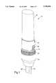
- FIG. 7is a perspective view of the end of a piece of the split fiber routing tube used in the present invention.
- FIG. 8is a perspective view of the closure of FIGS. 1 and 2 showing two splice trays attached to the transition tray of FIG. 6;
- FIG. 9is a perspective view similar to FIG. 8 but illustrating one splice tray held in an intermediate access position
- FIGS. 10A-10Care perspective views of alternative splice inserts used in accordance with the present invention.
- FIGS. 1 and 2there is depicted one embodiment 10 of the closure of the present invention. While this closure is particularly suited for use with fiber optic cables, many of the features described and claimed herein may be used with little or no modification in other applications, such as copper or coax.
- the disclosed embodimentshave general use in fiber-in-the-loop applications, including pedestals, cabinets, hand holes, strand mount, or on poles. These applications could include closures for fiber drops at video nodes in hybrid fiber/coax networks, distribution closures or fiber drop closures for fiber-to-the-curb or fiber-to-the-home networks.
- Closure 10is generally comprised of an outer housing and an inner framework, the housing including an elongate, dome body 12 having a first, closed end and a second, open end, a tubular base 14 attached to the open end of dome body 12, a latch wire 16 for releasably securing body 12 to base 14, and a base plate or strain relief member 18 which is obscured in FIG. 1 by a pre-stretched tube (PST) 20.
- PSTpre-stretched tube
- This housing constructionis similar to 3M's Reenterable Dome Closure used for splices of copper wire, except for strain relief member 18.
- two cables 22 and 24are shown entering closure 10, but the number of cables can vary.
- strain relief member 18has six cable ports designed to receive cables of varying diameters, and more than one cable may be placed in a single port if they are small diameter.
- Dome body 12, base 14 and strain relief member 18may be formed of any durable material, preferably a thermoplastic (injection-moldable) polymer such as polypropylene.
- the illustrated constructionis an above-ground closure for butt splicing.
- PST 20is preferably formed of an elastomer, such as EPDM, and is preloaded on a collapsible core, with either or both of its ends everted outwardly, i.e., wrapped backward on itself. After the cables are secured to strain relief member 18, and base 14 is positioned properly against member 18, PST 20 is placed about these two components and its core released, causing it to collapse about base 14 and strain relief member 18, and forming a tight, water-resistant seal along their interface.
- Ribsare provided along the outer surface of base 14 to engage PST 20.
- a gel end sealsuch as that shown in U.S. Pat. No. 5,258,578 may also be used.
- Access to the interior of closure 10is thereafter provided by removing dome body 12 from base 14 using latch 16.
- Latch 16which is preferably stainless steel, is pivotally attached to base 14 at two pins 26 formed with the base. Hairpin-shaped portions of latch 16 catch on corresponding pins 28 formed on body 12. The location of the hairpin-shaped portions and the positions of pins 26 and 28 are selected to cause body 12 to be forcibly urged against base 14 and form a tight seal therewith, the seal being further improved by an O-ring 30 which is placed near the top of base 14 in an annular groove 32 formed on the outer surface thereof. The diameter of O-ring 30 is matched to the width of groove 32 to provide an improved seal.
- strain relief member 18 of the present inventionuses a novel design which provides strain relief for the cable(s) entering closure 10, and allows quick and simple installation.
- Strain relief member 18includes a plate 34 having several cutouts, roughly U-shaped, forming cable ports 36, and allowing the cables to be placed in strain relief member 18 sideways, that is, without having to thread the cable through an opening.
- the platehas several outer surfaces 38, between adjacent ports 36, which coincide with the shape of the inner surface of base 14 such that strain relief member 18 may be placed partially inside base 14 and have a tight fit between the inner surface thereof and surfaces 38.
- a series of flanges or fingers 40 formed along surfaces 38snap around the bottom edge of base 14 for a solid connection.
- Plate 34also has a mounting fixture 42 for receiving the tray, back plate, terminal block, etc., which supports and stores the individual fibers (or wires) and associated interconnection devices.
- mounting fixture 42extends generally perpendicular to plate 34 and has a slot therein for receiving a tang or tab on the tray. The slot may be bent, or additional slots provided, for a more robust attachment.
- a portion of the inner surface of the portsis provided with several rows of bumps or teeth 44 which bite into the cable jacket or fitting material to more securely grasp the cable. Near these teeth, along the inner surface of ports 36, there are two entry slots or openings 46 which receive cable ties 48 (see FIGS. 2 and 6) for further securing the cable, and two exit slots 50 for the ties. Respective pairs of slots 46 and 50 are joined by self-guiding channels formed inside the walls of ports 36. More slots can be provided for additional cable ties, or only one, but two is deemed optimal. This construction allows for the quick installation of most cables onto strain relief member 18 in three simple steps. First, cables ties 48 are threaded into openings 46 and pushed until a sufficient length extends from exits 50.
- the cableis prepared, if necessary, for strain relief by wrapping the area to be clamped with a suitable fitting material, such as vinyl tape.
- ties 48are cinched tightly using pliers or a cable tie gun. After all cables are so secured, strain relief member 18 is locked into base 14 with fingers 40 snapped firmly against the bottom edge of base 14.
- An end sealsuch as those made of foam, may be used to provide resistance to water ingress.
- the cable jacketsmay be further secured within closure 10, for example, attached directly to the support member which is mounted on fixture 42, using conventional clamping devices, including those which provide electrical continuity across grounding sheaths.
- the cableis additionally provided with strength members (such as thick metallic wires or high-strength aramid fibers)
- the modified shield bond strain connector 52 shown in FIGS. 4 and 5may be used to secure these members.
- Connector 52utilizes two conventional clamping elements 54 and 56 which secure the cable jacket 58.
- Inner clamping element 56has a pin or bolt 60 which passes through a hole 62 in outer clamping element 54.
- Both elements 54 and 56have a plurality of tangs or teeth 64 formed thereon for gripping jacket 58.
- a series of tabs or prongs, including a central prong 66, formed at the upper end of element 56fit against complementary prongs 68.
- Shield bond extension 70has three holes 76, 78 and 80 therein.
- Hole 76is formed in a narrowed end portion 82 of extension element 70 and receives bolt 60 when connector 52 is assembled (narrowed end portion 82 is interposed between inner and outer clamping elements 54 and 56).
- Hole 78receives prong 66 of clamping element 56 which, with hole 76, serves to securely affix extension element 70 to clamping elements 54 and 56.
- Hole 80is adapted to receive another bolt 84 formed on extension clamping plate 72, whereby the strength members 74 may be secured between plate 72 and extension element 70.
- Bolt 84which extends the same direction as bolt 60 when extension element 70 is affixed to clamping elements 54 and 56, may be directly secured to the support member (or mounting fixture) inside closure 10.
- a flange 86 formed on the end of clamping plate 72serves to further stabilize the connection by providing a positive stop and friction fit with the upper edge 88 of extension element 70.
- the sides 90 of clamping plate 72are also bent to form flanges which similarly engage the sides of extension element 70.
- Clamping plate 72may have two notches therein so that the strength members can be bent back over the plate, in the notches, for addtional strain relief, and additional flanges may be provided, for example at the narrowed portion of element 70, to restrain the bent wires.
- Clamping plate 72 and extension element 70are preferably formed of a metallic material such as a copper alloy, e.g., brass, preferably with a tin plating.
- Connector 52has several advantages. First, it can handle any kind of strength member, e.g., wires or aramid fibers. It does not allow strength members to bow or buckle (for example, due to thermal cycling) because they are held at short distances from the cable sheath opening. This attribute is particularly significant in fiber optic applications. Connector 52 can be attached to different types of existing shield bond connectors, for conversion from copper shield bond to fiber shield bond. Since it terminates the strength member close to the jacket opening, it can be easily isolated from the fiber management devices in closure 10. Finally, because it is similar to the prior art copper shield bond connectors, the transition for technicians from copper to fiber will be easier.
- any kind of strength membere.g., wires or aramid fibers. It does not allow strength members to bow or buckle (for example, due to thermal cycling) because they are held at short distances from the cable sheath opening. This attribute is particularly significant in fiber optic applications.
- Connector 52can be attached to different types of existing shield bond connectors, for conversion from copper shield bond to fiber shield bond
- the inner framework of closure 10may take on various forms, but advantageously includes a back plate or transition tray 92 and one or more splice trays 94 each having a cover 96 and one or more splice inserts 98 for receiving splices 100 interconnecting a plurality of optical fibers 102.
- the term "splice”often refers to the permanent interconnection of two transmission lines, as opposed to a "connector” which usually connotes a device which may be attached, detached, and re-attached, repeatedly if necessary. These terms should not be so construed in such a limiting sense as used herein, however, since the present invention is equally usable with both devices that permanently connect and devices that temporarily connect.
- Transition tray 92is best seen in FIG. 6, and is elongate, having an attachment fixture 104 at one end for removable connection with mounting fixture 42 of strain relief member 18. Transition tray 92 has a floor 106 with two cylinders or spools 108 formed thereon for receiving coils of optical fiber slack, such as express fiber not used (spliced) at this location. Another curved wall 110 guides a fiber breakout tube 112 to one of the splice trays 94. Spools 108 and wall 110 maintain the optical fibers at a minimum bend radius. Tabs 114 may be used to retain the fibers in the tray.
- buffer tube fibercan be coiled on the plate's outer periphery and secured with cable ties.
- the tubeis terminated and secured with cable ties at the entrance and loose fiber is stored inside transition tray 92.
- Tray 92is preferably deep enough to allow multiple crossovers of ribbons.
- a foam blockmay be attached to the back side of tray 92, such as within the cylinder formed by the molding of the upper spool 108, to support the trays when the closure is open, i.e., dome body 12 is removed, and the trays are extending horizontally.
- Another piece of foam, such as a foam donutcan be placed around the free ends of the trays or pre-positioned within the closed end of body 12 to provide resistance against vibrations and external impacts.
- FIG. 7illustrates a novel split tube 116 which may be used to route the fibers from transition tray 92 to a splice tray 94, or from one splice tray to another.
- fiber routing tube 116keeps the fibers from being physically damaged, and resists bending the fiber to less than its minimum bend radius.
- tube 116is particularly suited for ribbon fiber; 12 fiber ribbons stack neatly in the rectangular cross-section interior, and this shape allows little twisting of the ribbons. Additionally, it can be installed on the fibers much quicker than cylindrical tubing or spiral wrap, by using an interlocking, releasable seam comprised of a longitudinal spline 118 extending the full length of the seam, and a complementary groove 120.
- Spline 118is enlarged or mushroomed at its tip, and groove 120 has a region of diminished width, to provide a dovetail or snap fit, but the material of tube 116 is sufficiently elastic (such as an EPDM/polypropylene blend) to allow the walls forming groove 120 to expand and allow spline 118 to fully enter groove 120 and seal tube 116 along its seam. Whatever tubing is used, it can advantageously travel below the tray pivot point to allow the fibers to move freely without catching on any hinges, and relax to their minimum stress state.
- splice trays 94are preferably the same general shape and size of transition tray 92, and have similar structures, including arcuate walls 122 for guiding the fibers, tabs 124 for retaining them, and channels 126 for constraining the fiber breakout tubes. Trays 94 are also preferably deep enough to allow multiple crossovers of ribbons. Channels 126 may have a snap feature to secure the tubes, or be used with cable ties. Splice trays 94 also have one or more pad areas or depressions 128 for receiving splice inserts 98.
- a clip 130may be provided on transition tray 92 to releasably secure the adjacent splice tray 94 in its storage position, and the splice trays 94 may be provided with similar clips 132. Overlapping tabs 134 formed on the sides of splice trays 94 help keep the trays neatly stacked.
- Transition tray 92 and splice trays 94are preferably molded from an injection-moldable thermoplastic polymer such as polycarbonate. When used with the other thermoplastic components described above (body 12, base 14 and strain relief member 18), absolutely no metal components are exposed within closure 10, which is desirable for storage of all dielectric cable, and for metallic sheath cable.
- Connector 52can be wrapped with, e.g., vinyl tape so that there is no exposed metal.
- tray hinge mechanismalso allows the tray hinge mechanism to be formed integrally with transition tray 92 and splice trays 94.
- pivot pins 136 and 138are formed in the upper surface of transition tray 92
- similar pivot pins 140 and 142are formed in the upper surfaces of splice trays 94.
- These pinsfit within hubs correspondingly positioned along the lower surfaces of the splice trays. Since these pins and hubs are formed at a common end of all of the trays, they can be accessed (inclined) without kinking the fibers routed around that end.
- the hubshave an outer wall with an irregular shape or detent, formed to bias the tray toward a position which is inclined 60° from the storage (flat) position, as shown in FIG. 9.
- the pivot pinsare nested in a socket having an inner surface with the same irregular shape as the outer wall of the hub. This feature allows hands-free access to fibers in trays below the top one(s), and integrally molded pins allow the trays to be pivoted without kinking or breaking fibers that enter and exit the tray.
- two buttons 144are pushed and the locking mechanism releases.
- FIGS. 10A-10CSeveral embodiments of the novel splice inserts 98 used with the present invention are shown in FIGS. 10A-10C. While inserts 98 are adapted to receive either fusion or mechanical splices, and for either discrete or ribbon fibers, they are equally suited to accommodate similar optical components such as couplers, splitters and attenuators.
- the insert 98a depicted in FIG. 10Ais designed for use with mass fusion splices, and includes a base or pad 146 having a shape generally corresponding to depressions 128 formed in splice trays 94 which, in the preferred embodiment, is rectangular or parallelogram.
- Insert 98ahas a plurality of fingers or arms 150a which are positioned to form a series of parallel nests or grooves for receiving individual splice elements. Arms 150a are staggered to provide a multi-point load on the splice elements, and are preferably constructed of an elastic material such as natural and synthetic rubbers, polyurethane, EPDM (or blends thereof with polypropylene), Neoprene or nitrile.
- Each of arms 150ahas a flange or hook 152 formed thereon, with the hooks along a given side of a splice element alternatively facing opposite directions; thus, in the depicted embodiment wherein three arms are provided on each side of the splice element, a given element is gripped by two hooks facing the same direction at its ends, and by a third hook facing the opposite direction at its center.
- FIG. 10Billustrates an alternative splice insert 98b adapted for use with discrete mechanical splices, such as the FIBRLOK splice 154 (FIBRLOK is a trademark of 3M).
- Arms 150bare similar to arms 150a although they are thinner than arms 150a and the hooks are less pronounced.
- splice insert 98chas been adapted for use with discrete fusion splice elements 156, and its arms 150c are nearly triangular in cross-section, with a lower corner missing to form the hook feature.
- Two layers of discrete fusion splicescan be stacked in the grooves of insert 98c to double its capacity, to twelve elements in the depicted embodiment.
- the present inventioneliminates the requirement in prior art splice inserts of added relief areas for displaced rubber, and avoids the tolerance build-up problems associated with elimination of these relief areas, in turn reducing the overall size of the insert, and enhancing and equalizing the retaining force on the splice elements. This is achieved by providing staggered arms which are also flexible, having a hardness in the range of 30 Shore A to 50 Shore D, preferably in the range of 60-80 Shore A, and most preferably about 70 Shore A.
- the construction of inserts 98a-98callow for easy insertion and removal of the splice element without damaging the element or the interconnected fibers.
Landscapes
- Physics & Mathematics (AREA)
- General Physics & Mathematics (AREA)
- Optics & Photonics (AREA)
- Cable Accessories (AREA)
- Light Guides In General And Applications Therefor (AREA)
- Insertion, Bundling And Securing Of Wires For Electric Apparatuses (AREA)
- Mechanical Coupling Of Light Guides (AREA)
- Installation Of Indoor Wiring (AREA)
- Storage Of Web-Like Or Filamentary Materials (AREA)
Abstract
Description
This is a continuation of application Ser. No. 08/414,189 filed Mar. 31, 1995 now abandoned.
1. Field of the Invention
The present invention generally relates to an enclosure that provides physical protection and storage for cables such as those used in telecommunications, and more particularly to an above-ground closure for optical fibers, splices and connectors therefor, having an improved strain relief member for securing the cables to the closure.
2. Description of the Prior Art
It is frequently necessary to join the ends of two cables, such as are used in telecommunications, to lengthen the cable system, branch off additional cables, or repair damaged cables. It is common to use enclosures to protect the joints, whether aerial, direct buried, above-ground or below ground (plant or hand hole). The enclosures are generally one of two types, in-line or butt-splice. In the butt splicing of fiber optic cables, several enclosure designs employ a dome shape, i.e., a closure body that is generally elongate, and has a closed end and an open end. Several such designs are depicted in U.S. Pat. Nos. 4,927,227, 5,222,183, 5,249,253 and 5,278,933, and in PCT Application No. GB93/00157.
These closures use various clamps, bolts, ties, etc., to secure the cable near the open end of the closure. See U.S. Pat. Nos. 5,097,529, 5,280,556 and 5,288,946, and PCT Application Nos. US93/05742, GB93/01120 and GB93/01942. These elements provide strain relief against cable stresses caused by external cable movement relative to the closure. A cable that is pulled or pushed axially, twisted, or bent must not transmit that motion to the cable sheath opening inside of the closure. The prior art designs are less suited for fiber optic cables, however, since they include metallic components have sharp edges which can damage exposed fibers and their coatings. These designs also require many parts, increasing the cost of the closure, and sometimes require special tools for installation. The use of so many interconnecting parts additionally increases installation time.
Some prior art cable terminations use shield bond connectors to additionally secure the cable jacket, and to provide electrical continuity across grounding sheaths, using metallic braids. These connectors typically have an inner clamping member which fits inside the cable jacket, and an outer clamping member which grips the outer surface of the cable jacket, and a bolt or other means for forcing the two members together to clamp the jacket therebetween. See, e.g., U.S. Pat. Nos. 3,787,797, 4,895,525 and 5,097,529, PCT Application No. US94/04198 and German Patent No. 4,231,181. These designs are inadequate to rejoin the integrity of the cable jacket for both fiber optic and copper cables since, for example, they cannot adequately handle the strength members found in fiber optic cables, such as wires or aramid fibers. Indeed, it would be very useful to have a connector that allowed for easier conversion from copper shield bond to fiber shield bond.
In several of the foregoing designs, fiber optic storage trays, such as splice trays, are supported by or attached to the strain relief member or closure body. The storage trays usually include guide walls to maintain the fibers with a minimum bend radius. In the aforementioned '227, '183, and '253 patents, and in U.S. Pat. Nos. 5,323,480 and 5,363,466, several splice trays, stacked during storage, are hinged to a common base, in a stair-step fashion. U.S. Pat. No. 5,071,220 and PCT Application No. US94/04232 show in-line closures having trays hinged to a common base in this manner. In U.S. Pat. No. 5,323,478, the trays are stacked by means of hinging strips. These hinging arrangements still allow the fibers traveling between adjacent splice trays to become kinked when the tray is lifted, inducing microbend losses in the fiber. They also do not make the best use of space due to the stair-step geometry.
Fibers that are routed between trays are often protected in spiral wrap tubing or cylindrical tubing to keep the fibers from being physically damaged and to resist bending of the fiber to less than its minimum bend radius. Cylindrical tubing and spiral wrap both take a fair amount of time to install since, for cylindrical tubing, the fibers must be threaded through the tubing and, for spiral wrap, the wrap must be hand coiled about the fibers, which can be very difficult if a long length of fiber is present. With spiral wrap, it is also easy to pinch a fiber as it is wrapped. Prior art fiber breakout tubes further do nothing to keep ribbon fiber from unduly twisting.
Several of the splice trays shown in the aforementioned patents use splice cradles which retain a plurality of splice elements. See also U.S. Pat Nos. 4,793,681, 4,840,449 and 4,854,661. The retention features can be molded directly into the tray surface, as disclosed in U.S. Pat. No. 5,074,635. Splice inserts can be removably attached to the trays, having retention features in the form of flexible cantilever latches for a snap fit; see U.S. Pat. Nos. 4,489,830, 4,679,896 and 5,375,185. These latches do not always firmly grip the splice elements, if many elements are present in adjacent grooves, due to the displacement and tolerance build-up of the material forming the retention feature. Repeated or extended use of the splice inserts can also lead to weakening of the retention members. In light of all of these problems, and particularly those associated with closures for fiber optic cables, it would be desirable and advantageous to devise a fiber optic closure having appropriate components to overcome the foregoing limitations.
The present invention provides a closure having improved cable strain relief, generally comprising an elongate body having a closed end and an open end, a tubular base having first and second ends, means for releasably securing the open end of the body to the first end of the base, and a strain relief member attached to the second end of the base. The strain relief member is composed entirely of non-metallic components, and includes a plate having cutouts therein forming cable ports, each of the cutouts having a wall and an inner surface along the wall, there being a plurality of gripping teeth along each inner surface, and each wall having at least one channel therein with entry and exit slots. A cable tie securing a cable in one of the cutouts is threaded through the channel, extending out the entry and exit slots. The plate advantageously has a plurality of outer surfaces shaped to fit snugly with an inner surface of the second end of the base, and flanges located at each outer surface for attachment to an edge of the second end of the base. A mounting fixture may be attached to the plate, adapted to receive an optical fiber storage tray. The plate, wall, mounting fixture and flanges may be integrally formed of an injection-moldable, thermoplastic polymer.
The invention will best be understood by reference to the accompanying drawings, wherein:
FIG. 1 is a perspective view of one embodiment of the fiber dome closure of the present invention, with two cables entering the closure;
FIG. 2 is a exploded view of the closure of FIG. 1;
FIG. 3 is a perspective view of one embodiment of the strain relief member used with the closure of FIGS. 1 and 2;
FIG. 4 is an exploded perspective view of a shield bond strain connector of the present invention;
FIG. 5 is a perspective view of the shield bond strain connector of FIG. 4 installed on a cable;
FIG. 6 is a perspective view of the closure of FIGS. 1 and 2 illustrating the transition tray;
FIG. 7 is a perspective view of the end of a piece of the split fiber routing tube used in the present invention;
FIG. 8 is a perspective view of the closure of FIGS. 1 and 2 showing two splice trays attached to the transition tray of FIG. 6;
FIG. 9 is a perspective view similar to FIG. 8 but illustrating one splice tray held in an intermediate access position;
FIGS. 10A-10C are perspective views of alternative splice inserts used in accordance with the present invention.
With reference now to the figures, and in particular with reference to FIGS. 1 and 2, there is depicted oneembodiment 10 of the closure of the present invention. While this closure is particularly suited for use with fiber optic cables, many of the features described and claimed herein may be used with little or no modification in other applications, such as copper or coax. The disclosed embodiments have general use in fiber-in-the-loop applications, including pedestals, cabinets, hand holes, strand mount, or on poles. These applications could include closures for fiber drops at video nodes in hybrid fiber/coax networks, distribution closures or fiber drop closures for fiber-to-the-curb or fiber-to-the-home networks.
With further reference to FIG. 3, thestrain relief member 18 of the present invention uses a novel design which provides strain relief for the cable(s) enteringclosure 10, and allows quick and simple installation.Strain relief member 18 includes aplate 34 having several cutouts, roughly U-shaped, formingcable ports 36, and allowing the cables to be placed instrain relief member 18 sideways, that is, without having to thread the cable through an opening. The plate has severalouter surfaces 38, betweenadjacent ports 36, which coincide with the shape of the inner surface ofbase 14 such thatstrain relief member 18 may be placed partially insidebase 14 and have a tight fit between the inner surface thereof and surfaces 38. A series of flanges orfingers 40 formed alongsurfaces 38 snap around the bottom edge ofbase 14 for a solid connection.Plate 34 also has a mountingfixture 42 for receiving the tray, back plate, terminal block, etc., which supports and stores the individual fibers (or wires) and associated interconnection devices. In the illustrated embodiment, mountingfixture 42 extends generally perpendicular to plate 34 and has a slot therein for receiving a tang or tab on the tray. The slot may be bent, or additional slots provided, for a more robust attachment.
A portion of the inner surface of the ports is provided with several rows of bumps orteeth 44 which bite into the cable jacket or fitting material to more securely grasp the cable. Near these teeth, along the inner surface ofports 36, there are two entry slots oropenings 46 which receive cable ties 48 (see FIGS. 2 and 6) for further securing the cable, and twoexit slots 50 for the ties. Respective pairs ofslots ports 36. More slots can be provided for additional cable ties, or only one, but two is deemed optimal. This construction allows for the quick installation of most cables ontostrain relief member 18 in three simple steps. First, cables ties 48 are threaded intoopenings 46 and pushed until a sufficient length extends from exits 50. Secondly, the cable is prepared, if necessary, for strain relief by wrapping the area to be clamped with a suitable fitting material, such as vinyl tape. Finally, with the cable in place in aport 36,ties 48 are cinched tightly using pliers or a cable tie gun. After all cables are so secured,strain relief member 18 is locked intobase 14 withfingers 40 snapped firmly against the bottom edge ofbase 14. An end seal, such as those made of foam, may be used to provide resistance to water ingress.
The cable jackets may be further secured withinclosure 10, for example, attached directly to the support member which is mounted onfixture 42, using conventional clamping devices, including those which provide electrical continuity across grounding sheaths. If the cable is additionally provided with strength members (such as thick metallic wires or high-strength aramid fibers), then the modified shieldbond strain connector 52 shown in FIGS. 4 and 5 may be used to secure these members.Connector 52 utilizes twoconventional clamping elements cable jacket 58.Inner clamping element 56 has a pin or bolt 60 which passes through ahole 62 inouter clamping element 54. Bothelements teeth 64 formed thereon for grippingjacket 58. A series of tabs or prongs, including acentral prong 66, formed at the upper end ofelement 56 fit againstcomplementary prongs 68.
The modification ofconnector 52 lies in the provision of twoadditional elements cable strength members 74.Shield bond extension 70 has threeholes Hole 76 is formed in anarrowed end portion 82 ofextension element 70 and receivesbolt 60 whenconnector 52 is assembled (narrowedend portion 82 is interposed between inner andouter clamping elements 54 and 56).Hole 78 receivesprong 66 of clampingelement 56 which, withhole 76, serves to securely affixextension element 70 to clampingelements Hole 80 is adapted to receive anotherbolt 84 formed onextension clamping plate 72, whereby thestrength members 74 may be secured betweenplate 72 andextension element 70.Bolt 84, which extends the same direction asbolt 60 whenextension element 70 is affixed to clampingelements closure 10. Aflange 86 formed on the end of clampingplate 72 serves to further stabilize the connection by providing a positive stop and friction fit with theupper edge 88 ofextension element 70. Thesides 90 of clampingplate 72 are also bent to form flanges which similarly engage the sides ofextension element 70. Clampingplate 72 may have two notches therein so that the strength members can be bent back over the plate, in the notches, for addtional strain relief, and additional flanges may be provided, for example at the narrowed portion ofelement 70, to restrain the bent wires. Clampingplate 72 andextension element 70 are preferably formed of a metallic material such as a copper alloy, e.g., brass, preferably with a tin plating.
Referring again to FIG. 2, the inner framework ofclosure 10 may take on various forms, but advantageously includes a back plate ortransition tray 92 and one ormore splice trays 94 each having acover 96 and one or more splice inserts 98 for receivingsplices 100 interconnecting a plurality ofoptical fibers 102. The term "splice" often refers to the permanent interconnection of two transmission lines, as opposed to a "connector" which usually connotes a device which may be attached, detached, and re-attached, repeatedly if necessary. These terms should not be so construed in such a limiting sense as used herein, however, since the present invention is equally usable with both devices that permanently connect and devices that temporarily connect.
Although only twosplice trays 94 are depicted, more could be provided in larger embodiments ofclosure 10.Transition tray 92 is best seen in FIG. 6, and is elongate, having anattachment fixture 104 at one end for removable connection with mountingfixture 42 ofstrain relief member 18.Transition tray 92 has afloor 106 with two cylinders or spools 108 formed thereon for receiving coils of optical fiber slack, such as express fiber not used (spliced) at this location. Anothercurved wall 110 guides afiber breakout tube 112 to one of thesplice trays 94.Spools 108 andwall 110 maintain the optical fibers at a minimum bend radius.Tabs 114 may be used to retain the fibers in the tray. If there is sufficient room insidedome body 12, buffer tube fiber can be coiled on the plate's outer periphery and secured with cable ties. For single tubes, the tube is terminated and secured with cable ties at the entrance and loose fiber is stored insidetransition tray 92. For express ribbon fiber, storage in "figure-8" patterns eliminates any twisting of the ribbons.Tray 92 is preferably deep enough to allow multiple crossovers of ribbons. A foam block may be attached to the back side oftray 92, such as within the cylinder formed by the molding of theupper spool 108, to support the trays when the closure is open, i.e.,dome body 12 is removed, and the trays are extending horizontally. Another piece of foam, such as a foam donut, can be placed around the free ends of the trays or pre-positioned within the closed end ofbody 12 to provide resistance against vibrations and external impacts.
FIG. 7 illustrates anovel split tube 116 which may be used to route the fibers fromtransition tray 92 to asplice tray 94, or from one splice tray to another. Like prior art articles,fiber routing tube 116 keeps the fibers from being physically damaged, and resists bending the fiber to less than its minimum bend radius. Unlike cylindrical tubing or spiral wrap,tube 116 is particularly suited for ribbon fiber; 12 fiber ribbons stack neatly in the rectangular cross-section interior, and this shape allows little twisting of the ribbons. Additionally, it can be installed on the fibers much quicker than cylindrical tubing or spiral wrap, by using an interlocking, releasable seam comprised of alongitudinal spline 118 extending the full length of the seam, and acomplementary groove 120.Spline 118 is enlarged or mushroomed at its tip, and groove 120 has a region of diminished width, to provide a dovetail or snap fit, but the material oftube 116 is sufficiently elastic (such as an EPDM/polypropylene blend) to allow thewalls forming groove 120 to expand and allowspline 118 to fully entergroove 120 andseal tube 116 along its seam. Whatever tubing is used, it can advantageously travel below the tray pivot point to allow the fibers to move freely without catching on any hinges, and relax to their minimum stress state.
Referring now to FIGS. 8 and 9,splice trays 94 are preferably the same general shape and size oftransition tray 92, and have similar structures, includingarcuate walls 122 for guiding the fibers,tabs 124 for retaining them, andchannels 126 for constraining the fiber breakout tubes.Trays 94 are also preferably deep enough to allow multiple crossovers of ribbons.Channels 126 may have a snap feature to secure the tubes, or be used with cable ties.Splice trays 94 also have one or more pad areas ordepressions 128 for receiving splice inserts 98. Aclip 130 may be provided ontransition tray 92 to releasably secure theadjacent splice tray 94 in its storage position, and thesplice trays 94 may be provided withsimilar clips 132. Overlappingtabs 134 formed on the sides ofsplice trays 94 help keep the trays neatly stacked.Transition tray 92 andsplice trays 94 are preferably molded from an injection-moldable thermoplastic polymer such as polycarbonate. When used with the other thermoplastic components described above (body 12,base 14 and strain relief member 18), absolutely no metal components are exposed withinclosure 10, which is desirable for storage of all dielectric cable, and for metallic sheath cable.Connector 52 can be wrapped with, e.g., vinyl tape so that there is no exposed metal.
The use of an injection-moldable material also allows the tray hinge mechanism to be formed integrally withtransition tray 92 andsplice trays 94. Specifically, pivot pins 136 and 138 are formed in the upper surface oftransition tray 92, and similar pivot pins 140 and 142 are formed in the upper surfaces ofsplice trays 94. These pins fit within hubs correspondingly positioned along the lower surfaces of the splice trays. Since these pins and hubs are formed at a common end of all of the trays, they can be accessed (inclined) without kinking the fibers routed around that end. The hubs have an outer wall with an irregular shape or detent, formed to bias the tray toward a position which is inclined 60° from the storage (flat) position, as shown in FIG. 9. The pivot pins are nested in a socket having an inner surface with the same irregular shape as the outer wall of the hub. This feature allows hands-free access to fibers in trays below the top one(s), and integrally molded pins allow the trays to be pivoted without kinking or breaking fibers that enter and exit the tray. To move asplice tray 94 back into alignment with the other trays, or flat againsttransition tray 92, twobuttons 144 are pushed and the locking mechanism releases.
Several embodiments of the novel splice inserts 98 used with the present invention are shown in FIGS. 10A-10C. Whileinserts 98 are adapted to receive either fusion or mechanical splices, and for either discrete or ribbon fibers, they are equally suited to accommodate similar optical components such as couplers, splitters and attenuators. Theinsert 98a depicted in FIG. 10A is designed for use with mass fusion splices, and includes a base or pad 146 having a shape generally corresponding todepressions 128 formed insplice trays 94 which, in the preferred embodiment, is rectangular or parallelogram. Ears 148 formed at the ends ofpad 146 mate with correspondingly-shaped cutouts formed intray 94 to help retaininsert 98a indepression 128. Other means could be provided to attach the pads to the trays, such as pressure-sensitive adhesive.Insert 98a has a plurality of fingers orarms 150a which are positioned to form a series of parallel nests or grooves for receiving individual splice elements.Arms 150a are staggered to provide a multi-point load on the splice elements, and are preferably constructed of an elastic material such as natural and synthetic rubbers, polyurethane, EPDM (or blends thereof with polypropylene), Neoprene or nitrile. Each ofarms 150a has a flange or hook 152 formed thereon, with the hooks along a given side of a splice element alternatively facing opposite directions; thus, in the depicted embodiment wherein three arms are provided on each side of the splice element, a given element is gripped by two hooks facing the same direction at its ends, and by a third hook facing the opposite direction at its center.
FIG. 10B illustrates an alternative splice insert 98b adapted for use with discrete mechanical splices, such as the FIBRLOK splice 154 (FIBRLOK is a trademark of 3M).Arms 150b are similar toarms 150a although they are thinner thanarms 150a and the hooks are less pronounced. In FIG. 10C, splice insert 98c has been adapted for use with discretefusion splice elements 156, and itsarms 150c are nearly triangular in cross-section, with a lower corner missing to form the hook feature. Two layers of discrete fusion splices can be stacked in the grooves of insert 98c to double its capacity, to twelve elements in the depicted embodiment.
The present invention eliminates the requirement in prior art splice inserts of added relief areas for displaced rubber, and avoids the tolerance build-up problems associated with elimination of these relief areas, in turn reducing the overall size of the insert, and enhancing and equalizing the retaining force on the splice elements. This is achieved by providing staggered arms which are also flexible, having a hardness in the range of 30 Shore A to 50 Shore D, preferably in the range of 60-80 Shore A, and most preferably about 70 Shore A. The construction ofinserts 98a-98c allow for easy insertion and removal of the splice element without damaging the element or the interconnected fibers.
Although the invention has been described with reference to specific embodiments, this description is not meant to be construed in a limiting sense. Various modifications of the disclosed embodiment, as well as alternative embodiments of the invention, will become apparent to persons skilled in the art upon reference to the description of the invention. For example, nearly all of the components can be used with in-line closures as well as dome closures. It is therefore contemplated that such modifications can be made without departing from the spirit or scope of the present invention as defined in the appended claims.
Claims (8)
1. An article for securing two or more cables and providing strain relief to the cables, comprising:
a base member having an open end and an edge at said open end; and
a strain relief member attached to said base member, said strain relief member including
a plate member having a plurality of cutouts each open to a side of said strain relief member and sized to receive one of the cables, and a plurality of outer surfaces shaped to fit snugly against an inner surface of said open end of said base member, said outer surfaces being formed between adjacent cutouts,
a mounting fixture attached to said plate member, extending generally perpendicular thereto and adapted to receive an optical fiber storage tray, said mounting fixture baking a slot for receiving an attachment tab on the tray, and
means, located at each of said outer surfaces, for attaching said plate member to said edge of said base member.
2. The article of claim 1 wherein said attaching means comprises a plurality of flanges, one at each of said outer surfaces, adapted to provide a snap fit with said edge of said base member.
3. The article of claim 1 wherein said base member, said plate member and said attaching means are constructed entirely of non-metallic materials.
4. The article of claim 3 wherein said plate member and said attaching means are integrally formed of an injection-moldable, thermoplastic polymer.
5. The article of claim 1 wherein each of said cutouts comprises a cable port having a U-shaped wall with a channel formed therein and first and second slots formed in opposing faces of said U-shaped wall said channel connecting said first and second slots on said opposing faces of said U-shaped wall such that a cable tie inserted into said first slot is self-guided through said channel to extend from said second slot.
6. The article of claim 5 further comprising a plurality of teeth formed in said U-shaped walls of said cutouts, for securely grasping an outer jacket of the cables.
7. The article of claim 6 wherein said plate member, said attaching means and said mounting fixture all are integrally formed of an injection-moldable, thermoplastic polymer.
8. A closure for butt splicing of optical fiber cables, comprising:
an elongate body having a closed end and an open end;
a tubular base having first and second ends;
means for releasably securing said open end of said body to said first end of said base;
a strain relief member attached to said second end of said base, said strain relief member composed entirely of non-metallic components and including a plate having a plurality of cutouts therein, each sized to receive one of the cables, each of said cutouts having a wall and an inner surface along said wall, there being a plurality of gripping teeth along each said inner surface, and each said wall having at least one channel therein with entry and exit slots formed in said inner surface for each said channel, said plate further having a plurality of outer surfaces shaped to fit snugly with an inner surface of said second end of said base, and flange means located at each said outer surface for attachment to an edge of said second end of said base;
at least one cable tie for securing a cable in one of said cutouts in said strain relief member, said cable tie being threaded through one of said channels, extending out entry and exit slots associated with said one channel;
a mounting fixture attached to said strain relief member, for receiving an optical fiber storage tray; and
a pre-stretched tube collapsed about said strain relief member and said second end of said base.
Priority Applications (1)
| Application Number | Priority Date | Filing Date | Title |
|---|---|---|---|
| US08/758,609US5758004A (en) | 1995-03-31 | 1996-11-27 | Closure with cable strain relief |
Applications Claiming Priority (2)
| Application Number | Priority Date | Filing Date | Title |
|---|---|---|---|
| US41418995A | 1995-03-31 | 1995-03-31 | |
| US08/758,609US5758004A (en) | 1995-03-31 | 1996-11-27 | Closure with cable strain relief |
Related Parent Applications (1)
| Application Number | Title | Priority Date | Filing Date |
|---|---|---|---|
| US41418995AContinuation | 1995-03-31 | 1995-03-31 |
Publications (1)
| Publication Number | Publication Date |
|---|---|
| US5758004Atrue US5758004A (en) | 1998-05-26 |
Family
ID=23640342
Family Applications (1)
| Application Number | Title | Priority Date | Filing Date |
|---|---|---|---|
| US08/758,609Expired - Fee RelatedUS5758004A (en) | 1995-03-31 | 1996-11-27 | Closure with cable strain relief |
Country Status (14)
| Country | Link |
|---|---|
| US (1) | US5758004A (en) |
| EP (1) | EP0817984B1 (en) |
| JP (1) | JPH11502946A (en) |
| KR (1) | KR19980703325A (en) |
| AR (1) | AR001806A1 (en) |
| AU (1) | AU697480B2 (en) |
| CA (1) | CA2215410A1 (en) |
| DE (1) | DE69608957T2 (en) |
| ES (1) | ES2147368T3 (en) |
| IL (1) | IL117333A0 (en) |
| NO (1) | NO974054L (en) |
| TW (1) | TW286371B (en) |
| WO (1) | WO1996030792A2 (en) |
| ZA (1) | ZA961996B (en) |
Cited By (119)
| Publication number | Priority date | Publication date | Assignee | Title |
|---|---|---|---|---|
| USD423460S (en) | 1999-01-05 | 2000-04-25 | Armin Thermodynamics | Contractor's temporary electrical service module |
| USD427897S (en)* | 1999-05-11 | 2000-07-11 | Ditel, Inc. | Fiber optic cable management clip |
| USD436027S1 (en) | 2000-06-05 | 2001-01-09 | Tyco Electronics Corporation | Cable retainer clip |
| US6269212B1 (en) | 1997-09-18 | 2001-07-31 | Pirelli Cavi E Sistemi S.P.A. | Method for performing fixing inside a container for optical connection components |
| US6271476B1 (en)* | 1999-12-13 | 2001-08-07 | The Siemon Company | Bend radius guide |
| US6388193B2 (en) | 2000-01-12 | 2002-05-14 | The Siemon Company | Stackable bend radius guide |
| US6396989B1 (en) | 1999-02-19 | 2002-05-28 | Tyco Electronics Corporation | Fiber optic cable retainer assembly and clip with a bend-radius control surface |
| US20020079198A1 (en)* | 1999-02-23 | 2002-06-27 | Nguyen Van Diep | Process and device for displacing a moveable unit on a base |
| US6413103B1 (en) | 2000-11-28 | 2002-07-02 | Apple Computer, Inc. | Method and apparatus for grounding microcoaxial cables inside a portable computing device |
| US6422900B1 (en) | 1999-09-15 | 2002-07-23 | Hh Tower Group | Coaxial cable coupling device |
| US6438311B1 (en) | 2000-08-14 | 2002-08-20 | Oni Systems Corp. | Cable retainer and cable organizer using same |
| US6438461B1 (en) | 1999-02-23 | 2002-08-20 | Newport Corporation | Method and device for displacing a moving body on a base mounted elastically with respect to the ground |
| USD468707S1 (en) | 2001-10-31 | 2003-01-14 | Hon Hai Precision Ind. Co., Ltd. | Holder of optical switch equipment |
| US6511035B1 (en) | 1999-08-03 | 2003-01-28 | Newport Corporation | Active vibration isolation systems with nonlinear compensation to account for actuator saturation |
| US6516130B1 (en) | 1998-12-30 | 2003-02-04 | Newport Corporation | Clip that aligns a fiber optic cable with a laser diode within a fiber optic module |
| US6539160B2 (en)* | 2000-10-27 | 2003-03-25 | Corning Cable Systems Llc | Optical fiber splicing and connecting assembly with coupler cassette |
| US6568666B2 (en) | 2001-06-13 | 2003-05-27 | Newport Corporation | Method for providing high vertical damping to pneumatic isolators during large amplitude disturbances of isolated payload |
| US6601524B2 (en) | 2001-03-28 | 2003-08-05 | Newport Corporation | Translation table with a spring biased dovetail bearing |
| US6614601B2 (en) | 1998-08-17 | 2003-09-02 | Newport Corporation | Gimballed optical mount |
| US6619611B2 (en) | 2001-07-02 | 2003-09-16 | Newport Corporation | Pneumatic vibration isolator utilizing an elastomeric element for isolation and attenuation of horizontal vibration |
| US20030209646A1 (en)* | 2002-05-07 | 2003-11-13 | Ryaboy Vyacheslav M. | Snubber for pneumatically isolated platforms |
| US6655840B2 (en) | 2001-02-13 | 2003-12-02 | Newport Corporation | Stiff cross roller bearing configuration |
| US6775458B2 (en)* | 2002-08-22 | 2004-08-10 | Corning Cable Systems Llc | Fixture for a flexible shuffle circuit |
| US6791058B2 (en) | 2001-04-25 | 2004-09-14 | Newport Corporation | Automatic laser weld machine for assembling photonic components |
| WO2004113982A1 (en) | 2003-06-23 | 2004-12-29 | Tyco Electronics Raychem Nv | Organiser for optical fibre cables |
| US20050135771A1 (en)* | 2003-12-15 | 2005-06-23 | Attanasio Daniel V. | Feedthrough fiber strain relief |
| US20050185910A1 (en)* | 2003-09-08 | 2005-08-25 | Adc Telecommunications, Inc. | Fiber optic cable and furcation module |
| US7018113B1 (en) | 2003-11-18 | 2006-03-28 | Optiworks, Inc. | Optical module package |
| US20060188210A1 (en)* | 2005-02-23 | 2006-08-24 | Adc Telecommunications, Inc. | Fiber optic furcation device including expansion chamber |
| US20060245168A1 (en)* | 2004-01-29 | 2006-11-02 | Tomonori Soeda | Disk array device and disk array device cable support method |
| US20070122100A1 (en)* | 2005-11-30 | 2007-05-31 | Steven Day | Slack storage system |
| US20070196060A1 (en)* | 2003-09-05 | 2007-08-23 | Hans Mickelsson | Method To Minimize Excess Cable Length |
| US7288720B1 (en) | 2006-09-19 | 2007-10-30 | Times Microwave Systems, Inc. | Grounding device for bundled cables |
| US7320455B2 (en) | 2003-10-24 | 2008-01-22 | Newport Corporation | Instrumented platform for vibration-sensitive equipment |
| US20080112680A1 (en)* | 2006-11-09 | 2008-05-15 | Mcgranahan Danny | Optical fiber slack storage for splice trays and splice assemblies |
| US20080112681A1 (en)* | 2004-02-06 | 2008-05-15 | Battey Jennifer A | Optical connection closure having at least one connector port |
| US20080131068A1 (en)* | 2004-03-08 | 2008-06-05 | Adc Telecommunications, Inc. | Fiber Access Terminal |
| US20080131069A1 (en)* | 2006-10-23 | 2008-06-05 | Adc Telecommunications, Inc. | Fiber Access Terminal including Moisture Barrier Plate with Punch Out |
| US20080138025A1 (en)* | 2004-11-03 | 2008-06-12 | Fiber Optics Network Solutions Corporation | Fiber Drop Terminal |
| US20080205844A1 (en)* | 2007-02-28 | 2008-08-28 | Guy Castonguay | Fiber optic splice trays |
| WO2008104282A1 (en)* | 2007-03-01 | 2008-09-04 | Adc Gmbh | Sleeve for optical waveguide cables |
| US20080232743A1 (en)* | 2007-03-23 | 2008-09-25 | Erik Gronvall | Drop terminal with anchor block for retaining a stub cable |
| US20090046985A1 (en)* | 2007-08-16 | 2009-02-19 | Erik Gronvall | Fiber Optic Enclosure Internal Cable Management |
| US20090103877A1 (en)* | 2006-05-30 | 2009-04-23 | Wolf Kluwe | Cable Sleeve for the Structured Storage and Handling of Optical Waveguides Guided in Optical Waveguide Cables |
| US20090103876A1 (en)* | 2006-05-30 | 2009-04-23 | Wolf Kluwe | Cable Sleeve for the Structured Storage and Handling of Optical Waveguides Guided in Optical Waveguide Cables |
| US20090123115A1 (en)* | 2007-10-09 | 2009-05-14 | Erik Gronvall | Drop Terminal Releasable Engagement Mechanism |
| US20090155617A1 (en)* | 2006-11-01 | 2009-06-18 | Korea University, Industry & Academy Collaboration Foundation Of Korea University, Industry & Academ | Iron-gold barcode nanowire and manufacturing method thereof |
| US7558458B2 (en) | 2007-03-08 | 2009-07-07 | Adc Telecommunications, Inc. | Universal bracket for mounting a drop terminal |
| US20100061692A1 (en)* | 2007-03-01 | 2010-03-11 | Adc Gmbh | Multifiber loose buffer receiving element for a distributing device for optical waveguides |
| US20100150515A1 (en)* | 2007-03-01 | 2010-06-17 | Adc Gmbh | Carrier system for mounting telecommunication and data technology devices |
| US20100183275A1 (en)* | 2007-03-01 | 2010-07-22 | Adc Gmbh | Carrier system for a distributing device for optical waveguides |
| US20100237757A1 (en)* | 2009-03-20 | 2010-09-23 | Emerson Network Power, Energy Systems, North America, Inc. | Distribution Hubs |
| US20100239210A1 (en)* | 2009-03-20 | 2010-09-23 | Wakileh George I | Multipurpose Telecommunications Modules |
| US7844158B2 (en) | 2007-10-09 | 2010-11-30 | Adc Telecommunications, Inc. | Mini drop terminal |
| US20100324877A1 (en)* | 2009-06-23 | 2010-12-23 | Kabushiki Kaisha Toshiba | Device property output apparatus and computer readable medium comprising program code for outputting device property |
| US7889961B2 (en) | 2008-03-27 | 2011-02-15 | Corning Cable Systems Llc | Compact, high-density adapter module, housing assembly and frame assembly for optical fiber telecommunications |
| US8231098B2 (en) | 2004-12-07 | 2012-07-31 | Newport Corporation | Methods and devices for active vibration damping of an optical structure |
| US20120235363A1 (en)* | 2009-12-03 | 2012-09-20 | Tyco Electronics Raychem Bvba | Gel sealing device |
| US8290329B2 (en) | 2006-01-04 | 2012-10-16 | Adc Telecommunications, Inc. | Fiber access terminal including moisture barrier plate |
| EP2520959A1 (en)* | 2011-05-05 | 2012-11-07 | CCS Technology, Inc. | Cable strain relief device for cable closures and cable closure having at least one such cable strain relief device |
| US8433171B2 (en) | 2009-06-19 | 2013-04-30 | Corning Cable Systems Llc | High fiber optic cable packing density apparatus |
| US8467651B2 (en) | 2009-09-30 | 2013-06-18 | Ccs Technology Inc. | Fiber optic terminals configured to dispose a fiber optic connection panel(s) within an optical fiber perimeter and related methods |
| US8520996B2 (en) | 2009-03-31 | 2013-08-27 | Corning Cable Systems Llc | Removably mountable fiber optic terminal |
| US8538226B2 (en) | 2009-05-21 | 2013-09-17 | Corning Cable Systems Llc | Fiber optic equipment guides and rails configured with stopping position(s), and related equipment and methods |
| US8542973B2 (en) | 2010-04-23 | 2013-09-24 | Ccs Technology, Inc. | Fiber optic distribution device |
| US8593828B2 (en) | 2010-02-04 | 2013-11-26 | Corning Cable Systems Llc | Communications equipment housings, assemblies, and related alignment features and methods |
| US8622481B2 (en) | 2011-01-25 | 2014-01-07 | Joy Mm Delaware, Inc. | Fiber optic cable protection in a mining system |
| US8625950B2 (en) | 2009-12-18 | 2014-01-07 | Corning Cable Systems Llc | Rotary locking apparatus for fiber optic equipment trays and related methods |
| US8660397B2 (en) | 2010-04-30 | 2014-02-25 | Corning Cable Systems Llc | Multi-layer module |
| US8662760B2 (en) | 2010-10-29 | 2014-03-04 | Corning Cable Systems Llc | Fiber optic connector employing optical fiber guide member |
| EP2717081A1 (en)* | 2012-10-02 | 2014-04-09 | 3M Innovative Properties Company | Optical fibre distribution enclosure |
| US8699838B2 (en) | 2009-05-14 | 2014-04-15 | Ccs Technology, Inc. | Fiber optic furcation module |
| US8705926B2 (en) | 2010-04-30 | 2014-04-22 | Corning Optical Communications LLC | Fiber optic housings having a removable top, and related components and methods |
| US8712206B2 (en) | 2009-06-19 | 2014-04-29 | Corning Cable Systems Llc | High-density fiber optic modules and module housings and related equipment |
| US8718436B2 (en) | 2010-08-30 | 2014-05-06 | Corning Cable Systems Llc | Methods, apparatuses for providing secure fiber optic connections |
| US8792767B2 (en) | 2010-04-16 | 2014-07-29 | Ccs Technology, Inc. | Distribution device |
| US8798427B2 (en) | 2007-09-05 | 2014-08-05 | Corning Cable Systems Llc | Fiber optic terminal assembly |
| US8861919B2 (en) | 2011-02-16 | 2014-10-14 | Tyco Electronics Corporation | Fiber optic closure |
| US8879881B2 (en) | 2010-04-30 | 2014-11-04 | Corning Cable Systems Llc | Rotatable routing guide and assembly |
| US8879882B2 (en) | 2008-10-27 | 2014-11-04 | Corning Cable Systems Llc | Variably configurable and modular local convergence point |
| US8909019B2 (en) | 2012-10-11 | 2014-12-09 | Ccs Technology, Inc. | System comprising a plurality of distribution devices and distribution device |
| US8913866B2 (en) | 2010-03-26 | 2014-12-16 | Corning Cable Systems Llc | Movable adapter panel |
| US20150001354A1 (en)* | 2012-01-25 | 2015-01-01 | Hydac Accessories GbmH | Mounting system |
| US8953924B2 (en) | 2011-09-02 | 2015-02-10 | Corning Cable Systems Llc | Removable strain relief brackets for securing fiber optic cables and/or optical fibers to fiber optic equipment, and related assemblies and methods |
| US8989547B2 (en) | 2011-06-30 | 2015-03-24 | Corning Cable Systems Llc | Fiber optic equipment assemblies employing non-U-width-sized housings and related methods |
| US8985862B2 (en) | 2013-02-28 | 2015-03-24 | Corning Cable Systems Llc | High-density multi-fiber adapter housings |
| US8995812B2 (en) | 2012-10-26 | 2015-03-31 | Ccs Technology, Inc. | Fiber optic management unit and fiber optic distribution device |
| US9008485B2 (en) | 2011-05-09 | 2015-04-14 | Corning Cable Systems Llc | Attachment mechanisms employed to attach a rear housing section to a fiber optic housing, and related assemblies and methods |
| US9004778B2 (en) | 2012-06-29 | 2015-04-14 | Corning Cable Systems Llc | Indexable optical fiber connectors and optical fiber connector arrays |
| US9020320B2 (en) | 2008-08-29 | 2015-04-28 | Corning Cable Systems Llc | High density and bandwidth fiber optic apparatuses and related equipment and methods |
| US9022814B2 (en) | 2010-04-16 | 2015-05-05 | Ccs Technology, Inc. | Sealing and strain relief device for data cables |
| US9038832B2 (en) | 2011-11-30 | 2015-05-26 | Corning Cable Systems Llc | Adapter panel support assembly |
| US9042702B2 (en) | 2012-09-18 | 2015-05-26 | Corning Cable Systems Llc | Platforms and systems for fiber optic cable attachment |
| US9049500B2 (en) | 2012-08-31 | 2015-06-02 | Corning Cable Systems Llc | Fiber optic terminals, systems, and methods for network service management |
| US9059578B2 (en) | 2009-02-24 | 2015-06-16 | Ccs Technology, Inc. | Holding device for a cable or an assembly for use with a cable |
| US9075216B2 (en) | 2009-05-21 | 2015-07-07 | Corning Cable Systems Llc | Fiber optic housings configured to accommodate fiber optic modules/cassettes and fiber optic panels, and related components and methods |
| US9075217B2 (en) | 2010-04-30 | 2015-07-07 | Corning Cable Systems Llc | Apparatuses and related components and methods for expanding capacity of fiber optic housings |
| US9213161B2 (en) | 2010-11-05 | 2015-12-15 | Corning Cable Systems Llc | Fiber body holder and strain relief device |
| US9219546B2 (en) | 2011-12-12 | 2015-12-22 | Corning Optical Communications LLC | Extremely high frequency (EHF) distributed antenna systems, and related components and methods |
| US9250409B2 (en) | 2012-07-02 | 2016-02-02 | Corning Cable Systems Llc | Fiber-optic-module trays and drawers for fiber-optic equipment |
| US9279951B2 (en) | 2010-10-27 | 2016-03-08 | Corning Cable Systems Llc | Fiber optic module for limited space applications having a partially sealed module sub-assembly |
| USRE45951E1 (en)* | 2007-01-16 | 2016-03-29 | Commscope Technologies Llc | Cable enclosure assemblies and methods for using the same |
| US9323020B2 (en) | 2008-10-09 | 2016-04-26 | Corning Cable Systems (Shanghai) Co. Ltd | Fiber optic terminal having adapter panel supporting both input and output fibers from an optical splitter |
| US9519118B2 (en) | 2010-04-30 | 2016-12-13 | Corning Optical Communications LLC | Removable fiber management sections for fiber optic housings, and related components and methods |
| USRE46255E1 (en)* | 2007-01-13 | 2016-12-27 | Commscope Technologies Llc | Fiber optic cable distribution box |
| US9547144B2 (en) | 2010-03-16 | 2017-01-17 | Corning Optical Communications LLC | Fiber optic distribution network for multiple dwelling units |
| US9547145B2 (en) | 2010-10-19 | 2017-01-17 | Corning Optical Communications LLC | Local convergence point for multiple dwelling unit fiber optic distribution network |
| US20170045704A1 (en)* | 2015-08-14 | 2017-02-16 | Electric Motion Company, Inc. | Buffer Tube Strain Relief |
| EP3151354A1 (en)* | 2009-12-03 | 2017-04-05 | CommScope Connectivity Belgium BVBA | Gel sealing device |
| US9632270B2 (en) | 2010-04-30 | 2017-04-25 | Corning Optical Communications LLC | Fiber optic housings configured for tool-less assembly, and related components and methods |
| US9634475B2 (en) | 2014-11-17 | 2017-04-25 | Caterpillar Inc. | Strain relief device for a harness or cable |
| US9645317B2 (en) | 2011-02-02 | 2017-05-09 | Corning Optical Communications LLC | Optical backplane extension modules, and related assemblies suitable for establishing optical connections to information processing modules disposed in equipment racks |
| US9720195B2 (en) | 2010-04-30 | 2017-08-01 | Corning Optical Communications LLC | Apparatuses and related components and methods for attachment and release of fiber optic housings to and from an equipment rack |
| US10094996B2 (en) | 2008-08-29 | 2018-10-09 | Corning Optical Communications, Llc | Independently translatable modules and fiber optic equipment trays in fiber optic equipment |
| US10110307B2 (en) | 2012-03-02 | 2018-10-23 | Corning Optical Communications LLC | Optical network units (ONUs) for high bandwidth connectivity, and related components and methods |
| WO2018234579A1 (en)* | 2017-06-23 | 2018-12-27 | CommScope Connectivity Belgium BVBA | ENCLOSURE OF TELECOMMUNICATIONS AND ASSOCIATED COMPONENTS |
| US10466434B2 (en)* | 2016-12-12 | 2019-11-05 | Multilink Inc. | Fiber optic splice tray and enclosure and method |
| WO2019222148A3 (en)* | 2018-05-14 | 2019-12-26 | Afl Telecommunications Llc | Butt closures and organizer assemblies therefor |
| US11294136B2 (en) | 2008-08-29 | 2022-04-05 | Corning Optical Communications LLC | High density and bandwidth fiber optic apparatuses and related equipment and methods |
Families Citing this family (7)
| Publication number | Priority date | Publication date | Assignee | Title |
|---|---|---|---|---|
| US5982971A (en)* | 1996-10-10 | 1999-11-09 | Tyco Submarine Systems Ltd. | Floating fiber storage assembly |
| DE10020995A1 (en)* | 2000-04-28 | 2001-10-31 | Bayerische Motoren Werke Ag | Receiving device for guiding and deflecting an optical waveguide |
| TW200832907A (en) | 2007-01-19 | 2008-08-01 | Holtek Semiconductor Inc | Apparatus for controlling an electrical cooker and related method thereof |
| EP2166389A1 (en) | 2008-09-23 | 2010-03-24 | 3M Innovative Properties Company | Enclosure for telecommunications cables, with removable organizer |
| US8903216B2 (en)* | 2011-03-07 | 2014-12-02 | Tyco Electronics Corporation | Cable strain relief clamping devices and methods for using the same |
| EP3571536A4 (en)* | 2017-01-20 | 2020-08-26 | 3975266 Canada Inc | FIBER OPTICAL CABLE EXTENSION SLEEVE FOR ACCOMMODATION OF A SPICE PROTECTION OF FUSED FIBER STRANDS |
| EP3966615A4 (en)* | 2019-05-07 | 2023-05-03 | Sterlite Technologies Ltd | HIGH DENSITY GLASS FIBER SLEEVE |
Citations (45)
| Publication number | Priority date | Publication date | Assignee | Title |
|---|---|---|---|---|
| US1980141A (en)* | 1932-02-06 | 1934-11-06 | Macgregor Instr Company | Cushion carrying case for syringe outfits and the like |
| US3431349A (en)* | 1967-12-28 | 1969-03-04 | Douglas L P Hamilton | Cable terminal enclosure with grounding cross bar |
| US3604835A (en)* | 1970-04-22 | 1971-09-14 | Douglas L P Hamilton | Terminal enclosure for buried cable plant |
| US3632069A (en)* | 1970-02-11 | 1972-01-04 | Panduit Corp | Bracket for mounting cable bundles in lightening holes |
| US3787797A (en)* | 1972-12-29 | 1974-01-22 | A Kurz | Grounding connectors for shielded cable |
| US4289288A (en)* | 1978-10-02 | 1981-09-15 | The Boeing Company | Wire routing apparatus |
| US4369944A (en)* | 1980-07-30 | 1983-01-25 | Western Electric Company, Inc. | Universal strand clamp and strand clamp assembly |
| US4373776A (en)* | 1980-06-30 | 1983-02-15 | Northern Telecom Limited | Protection case for optical fiber splices |
| US4489830A (en)* | 1983-12-12 | 1984-12-25 | Northern Telecom Limited | Retainer for packaged optical fiber splices and organizing tray utilizing such retainers |
| US4561708A (en)* | 1984-05-30 | 1985-12-31 | Minnesota Mining And Manufacturing Company | Cable shield connector |
| US4679896A (en)* | 1985-09-27 | 1987-07-14 | Preformed Line Products Company | Optical fiber splice organizer |
| US4793681A (en)* | 1988-04-18 | 1988-12-27 | Gte Products Corporation | Splice cradle |
| US4840449A (en)* | 1988-01-27 | 1989-06-20 | American Telephone And Telegraph Company, At&T Bell Laboratories | Optical fiber splice organizer |
| US4854661A (en)* | 1987-11-05 | 1989-08-08 | Gte Products Corporation | Splice cradle |
| US4895525A (en)* | 1989-01-31 | 1990-01-23 | A K Stamping Co. Inc. | Cable shield grounding clamp connector |
| US4898448A (en)* | 1988-05-02 | 1990-02-06 | Gte Products Corporation | Fiber distribution panel |
| US4927227A (en)* | 1988-10-31 | 1990-05-22 | At&T Bell Laboratories | Optical fiber cable closure |
| US5059748A (en)* | 1990-04-26 | 1991-10-22 | Raychem Corporation | Cable splice enclosure |
| US5071220A (en)* | 1989-05-11 | 1991-12-10 | L'etat Francais Represente Par Le Ministre Des Postes, Des Telecommunications Et Des L'espace (Centre National D'etudes Des Telecommunications) | Joint closure module and box for optical fiber cables |
| US5074635A (en)* | 1990-05-21 | 1991-12-24 | Minnesota Mining And Manufacturing Company | Splice tray and method |
| US5097529A (en)* | 1991-03-22 | 1992-03-17 | At&T Bell Laboratories | Space-saving optical fiber cable closure |
| WO1993000157A1 (en)* | 1991-06-26 | 1993-01-07 | Irvine Scientific Sales Co. | Mixing apparatus |
| WO1993001120A1 (en)* | 1991-07-08 | 1993-01-21 | Teuvo Siipola | Reel and method of manufacturing a reel |
| WO1993001942A1 (en)* | 1991-07-22 | 1993-02-04 | Eastman Kodak Company | Two-stage electrolytic graining process, aluminum sheet material produced thereby and lithographic printing plate comprising such aluminum sheet material |
| US5185845A (en)* | 1990-12-13 | 1993-02-09 | At&T Bell Laboratories | Optical fiber closure having enhanced storage capability |
| WO1993005742A1 (en)* | 1991-09-16 | 1993-04-01 | Breger Gibson Limited | Diaper |
| EP0538009A2 (en)* | 1991-10-15 | 1993-04-21 | THOMAS & BETTS CORPORATION | Method and apparatus for protection of cable splices |
| US5218664A (en)* | 1992-05-26 | 1993-06-08 | Siecor Corporation | Splice closure with lifting handles |
| US5222183A (en)* | 1988-11-07 | 1993-06-22 | N.V. Raychem S.A. | Splice case for optical fibre cable |
| US5249253A (en)* | 1984-04-11 | 1993-09-28 | Nv Raychem Sa | Electrofit fibre optics butt splice |
| US5258578A (en)* | 1992-02-18 | 1993-11-02 | Minnesota Mining And Manufacturing Company | Closure end seal |
| US5261024A (en)* | 1989-11-21 | 1993-11-09 | Raynet Corporation | Card cage used for coupling to telecommunications media |
| US5278933A (en)* | 1992-06-30 | 1994-01-11 | Hunsinger Terrance D | Fiber optic splice organizer and associated method |
| US5280556A (en)* | 1992-09-25 | 1994-01-18 | At&T Bell Laboratories | Cable closure which includes a cable sheath gripping assembly |
| US5288946A (en)* | 1992-06-18 | 1994-02-22 | Minnesota Mining And Manufacturing Company | Strain relief device and closure |
| WO1994004198A1 (en)* | 1992-08-18 | 1994-03-03 | Blixta Griffiths Pty. Limited | Steriliser |
| WO1994004232A1 (en)* | 1991-06-07 | 1994-03-03 | Daniel Desmarais | Method of playing an educational geography game |
| US5323478A (en)* | 1992-02-21 | 1994-06-21 | Mars Actel | Assembly of stacked and hinged modules |
| US5323480A (en)* | 1992-11-25 | 1994-06-21 | Raychem Corporation | Fiber optic splice closure |
| US5363466A (en)* | 1992-02-21 | 1994-11-08 | Mars Actel | Assembly of hinged flat modules |
| US5375185A (en)* | 1993-04-30 | 1994-12-20 | Keptel, Inc. | Apparatus for storing and organizing spliced optical fibers |
| US5399811A (en)* | 1990-09-13 | 1995-03-21 | Walter Rose Gmbh & Co. Kg | Device for sealing cables entering a cable coupling sleeve |
| US5446823A (en)* | 1994-01-26 | 1995-08-29 | Raychem Corporation | Aerial, pedestal, below grade, or buried optical fiber closure |
| US5472160A (en)* | 1994-06-22 | 1995-12-05 | At&T Corp. | Splice closure and grip block |
| US5481639A (en)* | 1994-10-28 | 1996-01-02 | At&T Corp. | Compact closure for optical fiber cable |
Family Cites Families (7)
| Publication number | Priority date | Publication date | Assignee | Title |
|---|---|---|---|---|
| US4039742A (en)* | 1974-11-22 | 1977-08-02 | Preformed Line Products Company | Waterproof cable splice enclosure kit |
| CA1152591A (en)* | 1979-08-07 | 1983-08-23 | Jean-Marie E. Nolf | Cable sleeve outlet for splice case |
| EP0439284A1 (en)* | 1990-01-18 | 1991-07-31 | BRITISH TELECOMMUNICATIONS public limited company | Cable closure |
| US5245133A (en)* | 1991-10-15 | 1993-09-14 | Thomas & Betts Corporation | Moisture-resistant cable splice and sealing structure thereof |
| GB9212624D0 (en)* | 1992-06-15 | 1992-07-29 | Raychem Sa Nv | Cable sealing device |
| US5308923A (en)* | 1992-06-16 | 1994-05-03 | Raychem Corporation | Enclosure assembly for telecommunication cables |
| WO2017213675A1 (en)* | 2016-06-10 | 2017-12-14 | Tredegar Film Products Corporation | Hydroformed expanded spun bonded nonwoven web and hydroformed composite material, and methods for making same |
- 1995
- 1995-05-01TWTW084104346Apatent/TW286371B/zhactive
- 1996
- 1996-02-23AUAU49297/96Apatent/AU697480B2/ennot_activeCeased
- 1996-02-23ESES96905569Tpatent/ES2147368T3/ennot_activeExpired - Lifetime
- 1996-02-23EPEP96905569Apatent/EP0817984B1/ennot_activeExpired - Lifetime
- 1996-02-23JPJP8529379Apatent/JPH11502946A/enactivePending
- 1996-02-23CACA002215410Apatent/CA2215410A1/ennot_activeAbandoned
- 1996-02-23DEDE69608957Tpatent/DE69608957T2/ennot_activeExpired - Fee Related
- 1996-02-23WOPCT/US1996/002428patent/WO1996030792A2/ennot_activeApplication Discontinuation
- 1996-02-23KRKR1019970706729Apatent/KR19980703325A/ennot_activeCeased
- 1996-03-01ILIL11733396Apatent/IL117333A0/enunknown
- 1996-03-12ZAZA9601996Apatent/ZA961996B/enunknown
- 1996-03-29ARAR33596796Apatent/AR001806A1/enunknown
- 1996-11-27USUS08/758,609patent/US5758004A/ennot_activeExpired - Fee Related
- 1997
- 1997-09-03NONO974054Apatent/NO974054L/enunknown
Patent Citations (45)
| Publication number | Priority date | Publication date | Assignee | Title |
|---|---|---|---|---|
| US1980141A (en)* | 1932-02-06 | 1934-11-06 | Macgregor Instr Company | Cushion carrying case for syringe outfits and the like |
| US3431349A (en)* | 1967-12-28 | 1969-03-04 | Douglas L P Hamilton | Cable terminal enclosure with grounding cross bar |
| US3632069A (en)* | 1970-02-11 | 1972-01-04 | Panduit Corp | Bracket for mounting cable bundles in lightening holes |
| US3604835A (en)* | 1970-04-22 | 1971-09-14 | Douglas L P Hamilton | Terminal enclosure for buried cable plant |
| US3787797A (en)* | 1972-12-29 | 1974-01-22 | A Kurz | Grounding connectors for shielded cable |
| US4289288A (en)* | 1978-10-02 | 1981-09-15 | The Boeing Company | Wire routing apparatus |
| US4373776A (en)* | 1980-06-30 | 1983-02-15 | Northern Telecom Limited | Protection case for optical fiber splices |
| US4369944A (en)* | 1980-07-30 | 1983-01-25 | Western Electric Company, Inc. | Universal strand clamp and strand clamp assembly |
| US4489830A (en)* | 1983-12-12 | 1984-12-25 | Northern Telecom Limited | Retainer for packaged optical fiber splices and organizing tray utilizing such retainers |
| US5249253A (en)* | 1984-04-11 | 1993-09-28 | Nv Raychem Sa | Electrofit fibre optics butt splice |
| US4561708A (en)* | 1984-05-30 | 1985-12-31 | Minnesota Mining And Manufacturing Company | Cable shield connector |
| US4679896A (en)* | 1985-09-27 | 1987-07-14 | Preformed Line Products Company | Optical fiber splice organizer |
| US4854661A (en)* | 1987-11-05 | 1989-08-08 | Gte Products Corporation | Splice cradle |
| US4840449A (en)* | 1988-01-27 | 1989-06-20 | American Telephone And Telegraph Company, At&T Bell Laboratories | Optical fiber splice organizer |
| US4793681A (en)* | 1988-04-18 | 1988-12-27 | Gte Products Corporation | Splice cradle |
| US4898448A (en)* | 1988-05-02 | 1990-02-06 | Gte Products Corporation | Fiber distribution panel |
| US4927227A (en)* | 1988-10-31 | 1990-05-22 | At&T Bell Laboratories | Optical fiber cable closure |
| US5222183A (en)* | 1988-11-07 | 1993-06-22 | N.V. Raychem S.A. | Splice case for optical fibre cable |
| US4895525A (en)* | 1989-01-31 | 1990-01-23 | A K Stamping Co. Inc. | Cable shield grounding clamp connector |
| US5071220A (en)* | 1989-05-11 | 1991-12-10 | L'etat Francais Represente Par Le Ministre Des Postes, Des Telecommunications Et Des L'espace (Centre National D'etudes Des Telecommunications) | Joint closure module and box for optical fiber cables |
| US5261024A (en)* | 1989-11-21 | 1993-11-09 | Raynet Corporation | Card cage used for coupling to telecommunications media |
| US5059748A (en)* | 1990-04-26 | 1991-10-22 | Raychem Corporation | Cable splice enclosure |
| US5074635A (en)* | 1990-05-21 | 1991-12-24 | Minnesota Mining And Manufacturing Company | Splice tray and method |
| US5399811A (en)* | 1990-09-13 | 1995-03-21 | Walter Rose Gmbh & Co. Kg | Device for sealing cables entering a cable coupling sleeve |
| US5185845A (en)* | 1990-12-13 | 1993-02-09 | At&T Bell Laboratories | Optical fiber closure having enhanced storage capability |
| US5097529A (en)* | 1991-03-22 | 1992-03-17 | At&T Bell Laboratories | Space-saving optical fiber cable closure |
| WO1994004232A1 (en)* | 1991-06-07 | 1994-03-03 | Daniel Desmarais | Method of playing an educational geography game |
| WO1993000157A1 (en)* | 1991-06-26 | 1993-01-07 | Irvine Scientific Sales Co. | Mixing apparatus |
| WO1993001120A1 (en)* | 1991-07-08 | 1993-01-21 | Teuvo Siipola | Reel and method of manufacturing a reel |
| WO1993001942A1 (en)* | 1991-07-22 | 1993-02-04 | Eastman Kodak Company | Two-stage electrolytic graining process, aluminum sheet material produced thereby and lithographic printing plate comprising such aluminum sheet material |
| WO1993005742A1 (en)* | 1991-09-16 | 1993-04-01 | Breger Gibson Limited | Diaper |
| EP0538009A2 (en)* | 1991-10-15 | 1993-04-21 | THOMAS & BETTS CORPORATION | Method and apparatus for protection of cable splices |
| US5258578A (en)* | 1992-02-18 | 1993-11-02 | Minnesota Mining And Manufacturing Company | Closure end seal |
| US5323478A (en)* | 1992-02-21 | 1994-06-21 | Mars Actel | Assembly of stacked and hinged modules |
| US5363466A (en)* | 1992-02-21 | 1994-11-08 | Mars Actel | Assembly of hinged flat modules |
| US5218664A (en)* | 1992-05-26 | 1993-06-08 | Siecor Corporation | Splice closure with lifting handles |
| US5288946A (en)* | 1992-06-18 | 1994-02-22 | Minnesota Mining And Manufacturing Company | Strain relief device and closure |
| US5278933A (en)* | 1992-06-30 | 1994-01-11 | Hunsinger Terrance D | Fiber optic splice organizer and associated method |
| WO1994004198A1 (en)* | 1992-08-18 | 1994-03-03 | Blixta Griffiths Pty. Limited | Steriliser |
| US5280556A (en)* | 1992-09-25 | 1994-01-18 | At&T Bell Laboratories | Cable closure which includes a cable sheath gripping assembly |
| US5323480A (en)* | 1992-11-25 | 1994-06-21 | Raychem Corporation | Fiber optic splice closure |
| US5375185A (en)* | 1993-04-30 | 1994-12-20 | Keptel, Inc. | Apparatus for storing and organizing spliced optical fibers |
| US5446823A (en)* | 1994-01-26 | 1995-08-29 | Raychem Corporation | Aerial, pedestal, below grade, or buried optical fiber closure |
| US5472160A (en)* | 1994-06-22 | 1995-12-05 | At&T Corp. | Splice closure and grip block |
| US5481639A (en)* | 1994-10-28 | 1996-01-02 | At&T Corp. | Compact closure for optical fiber cable |
Non-Patent Citations (7)
| Title |
|---|
| 3M Brochure "2524-F Fusion Splice Insert" Issue 1, Jun. 1991. |
| 3M Brochure "Fibrlok™ 2524 Splice Organizer Tray". Dated 1991. |
| 3M Brochure 2524 F Fusion Splice Insert Issue 1, Jun. 1991.* |
| 3M Brochure Fibrlok 2524 Splice Organizer Tray . Dated 1991.* |
| Article entitled "A Good Splice May Not Be As Good As You Think . . ." By Matthew Robinson, Outside Plant, pp. 36-38, Dec., 1994. |
| Article entitled A Good Splice May Not Be As Good As You Think . . . By Matthew Robinson, Outside Plant, pp. 36 38, Dec., 1994.* |
| Brochure entitled Goes Wherever Fiber Optic Cable Takes You. by Coyote Closure, P.O. Box 91129 Cleveland, OH 44101, dated 1995.* |
Cited By (204)
| Publication number | Priority date | Publication date | Assignee | Title |
|---|---|---|---|---|
| US6269212B1 (en) | 1997-09-18 | 2001-07-31 | Pirelli Cavi E Sistemi S.P.A. | Method for performing fixing inside a container for optical connection components |
| US6614601B2 (en) | 1998-08-17 | 2003-09-02 | Newport Corporation | Gimballed optical mount |
| US6608959B2 (en) | 1998-12-30 | 2003-08-19 | Newport Corporation | Apparatus and process for welding a fiber optic cable |
| US6516130B1 (en) | 1998-12-30 | 2003-02-04 | Newport Corporation | Clip that aligns a fiber optic cable with a laser diode within a fiber optic module |
| USD423460S (en) | 1999-01-05 | 2000-04-25 | Armin Thermodynamics | Contractor's temporary electrical service module |
| US6396989B1 (en) | 1999-02-19 | 2002-05-28 | Tyco Electronics Corporation | Fiber optic cable retainer assembly and clip with a bend-radius control surface |
| US6996506B2 (en) | 1999-02-23 | 2006-02-07 | Newport Corporation | Process and device for displacing a moveable unit on a base |
| US20050126892A9 (en)* | 1999-02-23 | 2005-06-16 | Nguyen Van D. | Process and device for displacing a moveable unit on a base |
| US20020079198A1 (en)* | 1999-02-23 | 2002-06-27 | Nguyen Van Diep | Process and device for displacing a moveable unit on a base |
| US6438461B1 (en) | 1999-02-23 | 2002-08-20 | Newport Corporation | Method and device for displacing a moving body on a base mounted elastically with respect to the ground |
| USD427897S (en)* | 1999-05-11 | 2000-07-11 | Ditel, Inc. | Fiber optic cable management clip |
| US6511035B1 (en) | 1999-08-03 | 2003-01-28 | Newport Corporation | Active vibration isolation systems with nonlinear compensation to account for actuator saturation |
| US6422900B1 (en) | 1999-09-15 | 2002-07-23 | Hh Tower Group | Coaxial cable coupling device |
| US6271476B1 (en)* | 1999-12-13 | 2001-08-07 | The Siemon Company | Bend radius guide |
| US6388193B2 (en) | 2000-01-12 | 2002-05-14 | The Siemon Company | Stackable bend radius guide |
| USD436027S1 (en) | 2000-06-05 | 2001-01-09 | Tyco Electronics Corporation | Cable retainer clip |
| US6438311B1 (en) | 2000-08-14 | 2002-08-20 | Oni Systems Corp. | Cable retainer and cable organizer using same |
| US6539160B2 (en)* | 2000-10-27 | 2003-03-25 | Corning Cable Systems Llc | Optical fiber splicing and connecting assembly with coupler cassette |
| US6413103B1 (en) | 2000-11-28 | 2002-07-02 | Apple Computer, Inc. | Method and apparatus for grounding microcoaxial cables inside a portable computing device |
| US6655840B2 (en) | 2001-02-13 | 2003-12-02 | Newport Corporation | Stiff cross roller bearing configuration |
| US6601524B2 (en) | 2001-03-28 | 2003-08-05 | Newport Corporation | Translation table with a spring biased dovetail bearing |
| US6791058B2 (en) | 2001-04-25 | 2004-09-14 | Newport Corporation | Automatic laser weld machine for assembling photonic components |
| US6568666B2 (en) | 2001-06-13 | 2003-05-27 | Newport Corporation | Method for providing high vertical damping to pneumatic isolators during large amplitude disturbances of isolated payload |
| US6619611B2 (en) | 2001-07-02 | 2003-09-16 | Newport Corporation | Pneumatic vibration isolator utilizing an elastomeric element for isolation and attenuation of horizontal vibration |
| USD468707S1 (en) | 2001-10-31 | 2003-01-14 | Hon Hai Precision Ind. Co., Ltd. | Holder of optical switch equipment |
| US20030209646A1 (en)* | 2002-05-07 | 2003-11-13 | Ryaboy Vyacheslav M. | Snubber for pneumatically isolated platforms |
| US6966535B2 (en) | 2002-05-07 | 2005-11-22 | Newport Corporation | Snubber for pneumatically isolated platforms |
| US6775458B2 (en)* | 2002-08-22 | 2004-08-10 | Corning Cable Systems Llc | Fixture for a flexible shuffle circuit |
| WO2004113982A1 (en) | 2003-06-23 | 2004-12-29 | Tyco Electronics Raychem Nv | Organiser for optical fibre cables |
| US20070196060A1 (en)* | 2003-09-05 | 2007-08-23 | Hans Mickelsson | Method To Minimize Excess Cable Length |
| US20050185910A1 (en)* | 2003-09-08 | 2005-08-25 | Adc Telecommunications, Inc. | Fiber optic cable and furcation module |
| US8311379B2 (en) | 2003-09-08 | 2012-11-13 | Adc Telecommunications, Inc. | Fiber optic cable and furcation module |
| USRE49374E1 (en) | 2003-09-08 | 2023-01-17 | Commscope Technologies Llc | Fiber optic cable and furcation module |
| USRE47069E1 (en) | 2003-09-08 | 2018-10-02 | Commscope Technologies Llc | Fiber optic cable and furcation module |
| US7320455B2 (en) | 2003-10-24 | 2008-01-22 | Newport Corporation | Instrumented platform for vibration-sensitive equipment |
| US7018113B1 (en) | 2003-11-18 | 2006-03-28 | Optiworks, Inc. | Optical module package |
| US20050135771A1 (en)* | 2003-12-15 | 2005-06-23 | Attanasio Daniel V. | Feedthrough fiber strain relief |
| US7373072B2 (en)* | 2003-12-15 | 2008-05-13 | Weatherford/Lamb, Inc. | Feedthrough fiber strain relief |
| US20060245168A1 (en)* | 2004-01-29 | 2006-11-02 | Tomonori Soeda | Disk array device and disk array device cable support method |
| US20080112681A1 (en)* | 2004-02-06 | 2008-05-15 | Battey Jennifer A | Optical connection closure having at least one connector port |
| US7941027B2 (en) | 2004-03-08 | 2011-05-10 | Adc Telecommunications, Inc. | Fiber access terminal |
| US20080131068A1 (en)* | 2004-03-08 | 2008-06-05 | Adc Telecommunications, Inc. | Fiber Access Terminal |
| US20090297112A1 (en)* | 2004-03-08 | 2009-12-03 | Adc Telecommunications, Inc. | Fiber access terminal |
| US7400815B2 (en) | 2004-03-08 | 2008-07-15 | Adc Telecommunications, Inc. | Fiber access terminal |
| US7539387B2 (en) | 2004-03-08 | 2009-05-26 | Adc Telecommunications, Inc. | Fiber access terminal |
| US20080226252A1 (en)* | 2004-03-08 | 2008-09-18 | Adc Telecommunications, Inc. | Fiber Access Terminal |
| US8363999B2 (en) | 2004-03-08 | 2013-01-29 | Adc Telecommunications, Inc. | Fiber access terminal |
| US7539388B2 (en) | 2004-03-08 | 2009-05-26 | Adc Telecommunications, Inc. | Fiber access terminal |
| US20080260344A1 (en)* | 2004-03-08 | 2008-10-23 | Adc Telecommunications, Inc. | Fiber access terminal |
| US20080260345A1 (en)* | 2004-03-08 | 2008-10-23 | Adc Telecommunications, Inc. | Fiber access terminal |
| US7480437B2 (en) | 2004-03-08 | 2009-01-20 | Adc Telecommunications, Inc. | Fiber access terminal |
| US20080138025A1 (en)* | 2004-11-03 | 2008-06-12 | Fiber Optics Network Solutions Corporation | Fiber Drop Terminal |
| US7627222B2 (en) | 2004-11-03 | 2009-12-01 | Adc Telecommunications, Inc. | Fiber drop terminal |
| US8651447B2 (en) | 2004-12-07 | 2014-02-18 | Newport Corporation | Methods and devices for active vibration damping of an optical structure |
| US8231098B2 (en) | 2004-12-07 | 2012-07-31 | Newport Corporation | Methods and devices for active vibration damping of an optical structure |
| US7505663B2 (en)* | 2005-02-23 | 2009-03-17 | Adc Telecommunications, Inc. | Fiber optic furcation device including expansion chamber |
| US20090103871A1 (en)* | 2005-02-23 | 2009-04-23 | Adc Telecommunications, Inc. | Fiber optic furcation device including expansion chamber |
| US20060188210A1 (en)* | 2005-02-23 | 2006-08-24 | Adc Telecommunications, Inc. | Fiber optic furcation device including expansion chamber |
| US7433570B2 (en)* | 2005-11-30 | 2008-10-07 | Tunnel Mill Polymer, Inc. | Slack storage system |
| US20070122100A1 (en)* | 2005-11-30 | 2007-05-31 | Steven Day | Slack storage system |
| US8290329B2 (en) | 2006-01-04 | 2012-10-16 | Adc Telecommunications, Inc. | Fiber access terminal including moisture barrier plate |
| US20090103877A1 (en)* | 2006-05-30 | 2009-04-23 | Wolf Kluwe | Cable Sleeve for the Structured Storage and Handling of Optical Waveguides Guided in Optical Waveguide Cables |
| US20090103876A1 (en)* | 2006-05-30 | 2009-04-23 | Wolf Kluwe | Cable Sleeve for the Structured Storage and Handling of Optical Waveguides Guided in Optical Waveguide Cables |
| US8055114B2 (en) | 2006-05-30 | 2011-11-08 | Ccs Technology, Inc. | Cable sleeve for the structured storage and handling of optical waveguides guided in optical waveguide cables |
| US7689090B2 (en) | 2006-05-30 | 2010-03-30 | Ccs Technology, Inc. | Cable sleeve for the structured storage and handling of optical waveguides guided in optical waveguide cables |
| US7288720B1 (en) | 2006-09-19 | 2007-10-30 | Times Microwave Systems, Inc. | Grounding device for bundled cables |
| US7715683B2 (en) | 2006-10-23 | 2010-05-11 | Adc Telecommunications, Inc. | Fiber access terminal including moisture barrier plate with punch out |
| US7526173B2 (en)* | 2006-10-23 | 2009-04-28 | Adc Telecommunications, Inc. | Fiber access terminal including moisture barrier plate with punch out |
| US20080131069A1 (en)* | 2006-10-23 | 2008-06-05 | Adc Telecommunications, Inc. | Fiber Access Terminal including Moisture Barrier Plate with Punch Out |
| US20090185783A1 (en)* | 2006-10-23 | 2009-07-23 | Adc Telecommunications, Inc. | Fiber access terminal including moisture barrier plate with punch out |
| US20090155617A1 (en)* | 2006-11-01 | 2009-06-18 | Korea University, Industry & Academy Collaboration Foundation Of Korea University, Industry & Academ | Iron-gold barcode nanowire and manufacturing method thereof |
| US7936960B2 (en) | 2006-11-09 | 2011-05-03 | Corning Cable Systems Llc | Optical fiber slack storage for splice trays and splice assemblies |
| US20080112680A1 (en)* | 2006-11-09 | 2008-05-15 | Mcgranahan Danny | Optical fiber slack storage for splice trays and splice assemblies |
| USRE46255E1 (en)* | 2007-01-13 | 2016-12-27 | Commscope Technologies Llc | Fiber optic cable distribution box |
| USRE48063E1 (en)* | 2007-01-13 | 2020-06-23 | Commscope Technologies Llc | Fiber optic cable distribution box |
| USRE49385E1 (en) | 2007-01-13 | 2023-01-24 | Commscope Technologies Llc | Fiber optic cable distribution box |
| USRE45951E1 (en)* | 2007-01-16 | 2016-03-29 | Commscope Technologies Llc | Cable enclosure assemblies and methods for using the same |
| USRE46547E1 (en) | 2007-01-16 | 2017-09-12 | Commscope Technologies Llc | Cable enclosure assemblies and methods for using the same |
| US20080205844A1 (en)* | 2007-02-28 | 2008-08-28 | Guy Castonguay | Fiber optic splice trays |
| US7822310B2 (en) | 2007-02-28 | 2010-10-26 | Corning Cable Systems Llc | Fiber optic splice trays |
| US8121455B2 (en) | 2007-03-01 | 2012-02-21 | Adc Gmbh | Carrier system for mounting telecommunication and data technology devices |
| US20100183275A1 (en)* | 2007-03-01 | 2010-07-22 | Adc Gmbh | Carrier system for a distributing device for optical waveguides |
| US20100150515A1 (en)* | 2007-03-01 | 2010-06-17 | Adc Gmbh | Carrier system for mounting telecommunication and data technology devices |
| US20100061692A1 (en)* | 2007-03-01 | 2010-03-11 | Adc Gmbh | Multifiber loose buffer receiving element for a distributing device for optical waveguides |
| US20100061686A1 (en)* | 2007-03-01 | 2010-03-11 | Adc Gmbh | Sleeve for optical waveguide cables |
| WO2008104282A1 (en)* | 2007-03-01 | 2008-09-04 | Adc Gmbh | Sleeve for optical waveguide cables |
| US8280215B2 (en) | 2007-03-01 | 2012-10-02 | Adc Gmbh | Multifiber loose buffer receiving element for a distributing device for optical waveguides |
| US7558458B2 (en) | 2007-03-08 | 2009-07-07 | Adc Telecommunications, Inc. | Universal bracket for mounting a drop terminal |
| US7512304B2 (en) | 2007-03-23 | 2009-03-31 | Adc Telecommunications, Inc. | Drop terminal with anchor block for retaining a stub cable |
| US20080232743A1 (en)* | 2007-03-23 | 2008-09-25 | Erik Gronvall | Drop terminal with anchor block for retaining a stub cable |
| US20090046985A1 (en)* | 2007-08-16 | 2009-02-19 | Erik Gronvall | Fiber Optic Enclosure Internal Cable Management |
| US8798427B2 (en) | 2007-09-05 | 2014-08-05 | Corning Cable Systems Llc | Fiber optic terminal assembly |
| US20090123115A1 (en)* | 2007-10-09 | 2009-05-14 | Erik Gronvall | Drop Terminal Releasable Engagement Mechanism |
| US8213761B2 (en) | 2007-10-09 | 2012-07-03 | Adc Telecommunications | Mini drop terminal |
| US7844158B2 (en) | 2007-10-09 | 2010-11-30 | Adc Telecommunications, Inc. | Mini drop terminal |
| US7903923B2 (en) | 2007-10-09 | 2011-03-08 | Adc Telecommunications, Inc. | Drop terminal releasable engagement mechanism |
| US20110067452A1 (en)* | 2007-10-09 | 2011-03-24 | Adc Telecommunications, Inc. | Mini drop terminal |
| US7889961B2 (en) | 2008-03-27 | 2011-02-15 | Corning Cable Systems Llc | Compact, high-density adapter module, housing assembly and frame assembly for optical fiber telecommunications |
| US10126514B2 (en) | 2008-08-29 | 2018-11-13 | Corning Optical Communications, Llc | Independently translatable modules and fiber optic equipment trays in fiber optic equipment |
| US10094996B2 (en) | 2008-08-29 | 2018-10-09 | Corning Optical Communications, Llc | Independently translatable modules and fiber optic equipment trays in fiber optic equipment |
| US11609396B2 (en) | 2008-08-29 | 2023-03-21 | Corning Optical Communications LLC | High density and bandwidth fiber optic apparatuses and related equipment and methods |
| US9910236B2 (en) | 2008-08-29 | 2018-03-06 | Corning Optical Communications LLC | High density and bandwidth fiber optic apparatuses and related equipment and methods |
| US11754796B2 (en) | 2008-08-29 | 2023-09-12 | Corning Optical Communications LLC | Independently translatable modules and fiber optic equipment trays in fiber optic equipment |
| US10120153B2 (en) | 2008-08-29 | 2018-11-06 | Corning Optical Communications, Llc | Independently translatable modules and fiber optic equipment trays in fiber optic equipment |
| US9020320B2 (en) | 2008-08-29 | 2015-04-28 | Corning Cable Systems Llc | High density and bandwidth fiber optic apparatuses and related equipment and methods |
| US11294135B2 (en) | 2008-08-29 | 2022-04-05 | Corning Optical Communications LLC | High density and bandwidth fiber optic apparatuses and related equipment and methods |
| US12072545B2 (en) | 2008-08-29 | 2024-08-27 | Corning Optical Communications LLC | High density and bandwidth fiber optic apparatuses and related equipment and methods |
| US11294136B2 (en) | 2008-08-29 | 2022-04-05 | Corning Optical Communications LLC | High density and bandwidth fiber optic apparatuses and related equipment and methods |
| US10222570B2 (en) | 2008-08-29 | 2019-03-05 | Corning Optical Communications LLC | Independently translatable modules and fiber optic equipment trays in fiber optic equipment |
| US11092767B2 (en) | 2008-08-29 | 2021-08-17 | Corning Optical Communications LLC | High density and bandwidth fiber optic apparatuses and related equipment and methods |
| US11086089B2 (en) | 2008-08-29 | 2021-08-10 | Corning Optical Communications LLC | High density and bandwidth fiber optic apparatuses and related equipment and methods |
| US10416405B2 (en) | 2008-08-29 | 2019-09-17 | Corning Optical Communications LLC | Independently translatable modules and fiber optic equipment trays in fiber optic equipment |
| US10422971B2 (en) | 2008-08-29 | 2019-09-24 | Corning Optical Communicatinos LLC | High density and bandwidth fiber optic apparatuses and related equipment and methods |
| US10444456B2 (en) | 2008-08-29 | 2019-10-15 | Corning Optical Communications LLC | High density and bandwidth fiber optic apparatuses and related equipment and methods |
| US10852499B2 (en) | 2008-08-29 | 2020-12-01 | Corning Optical Communications LLC | High density and bandwidth fiber optic apparatuses and related equipment and methods |
| US10459184B2 (en) | 2008-08-29 | 2019-10-29 | Corning Optical Communications LLC | High density and bandwidth fiber optic apparatuses and related equipment and methods |
| US10564378B2 (en) | 2008-08-29 | 2020-02-18 | Corning Optical Communications LLC | High density and bandwidth fiber optic apparatuses and related equipment and methods |
| US10606014B2 (en) | 2008-08-29 | 2020-03-31 | Corning Optical Communications LLC | Independently translatable modules and fiber optic equipment trays in fiber optic equipment |
| US9323020B2 (en) | 2008-10-09 | 2016-04-26 | Corning Cable Systems (Shanghai) Co. Ltd | Fiber optic terminal having adapter panel supporting both input and output fibers from an optical splitter |
| US8879882B2 (en) | 2008-10-27 | 2014-11-04 | Corning Cable Systems Llc | Variably configurable and modular local convergence point |
| US9059578B2 (en) | 2009-02-24 | 2015-06-16 | Ccs Technology, Inc. | Holding device for a cable or an assembly for use with a cable |
| US20100237757A1 (en)* | 2009-03-20 | 2010-09-23 | Emerson Network Power, Energy Systems, North America, Inc. | Distribution Hubs |
| US20100239210A1 (en)* | 2009-03-20 | 2010-09-23 | Wakileh George I | Multipurpose Telecommunications Modules |
| US8520996B2 (en) | 2009-03-31 | 2013-08-27 | Corning Cable Systems Llc | Removably mountable fiber optic terminal |
| US8699838B2 (en) | 2009-05-14 | 2014-04-15 | Ccs Technology, Inc. | Fiber optic furcation module |
| US8538226B2 (en) | 2009-05-21 | 2013-09-17 | Corning Cable Systems Llc | Fiber optic equipment guides and rails configured with stopping position(s), and related equipment and methods |
| US9075216B2 (en) | 2009-05-21 | 2015-07-07 | Corning Cable Systems Llc | Fiber optic housings configured to accommodate fiber optic modules/cassettes and fiber optic panels, and related components and methods |
| US8712206B2 (en) | 2009-06-19 | 2014-04-29 | Corning Cable Systems Llc | High-density fiber optic modules and module housings and related equipment |
| US8433171B2 (en) | 2009-06-19 | 2013-04-30 | Corning Cable Systems Llc | High fiber optic cable packing density apparatus |
| US20100324877A1 (en)* | 2009-06-23 | 2010-12-23 | Kabushiki Kaisha Toshiba | Device property output apparatus and computer readable medium comprising program code for outputting device property |
| US8467651B2 (en) | 2009-09-30 | 2013-06-18 | Ccs Technology Inc. | Fiber optic terminals configured to dispose a fiber optic connection panel(s) within an optical fiber perimeter and related methods |
| US11784480B2 (en)* | 2009-12-03 | 2023-10-10 | CommScope Connectivity Belgium BVBA | Gel sealing device |
| US9768604B2 (en) | 2009-12-03 | 2017-09-19 | CommScope Connectivity Belgium BVBA | Gel sealing device |
| US20210226435A1 (en)* | 2009-12-03 | 2021-07-22 | CommScope Connectivity Belgium BVBA | Gel sealing device |
| US20120235363A1 (en)* | 2009-12-03 | 2012-09-20 | Tyco Electronics Raychem Bvba | Gel sealing device |
| US10298003B2 (en) | 2009-12-03 | 2019-05-21 | CommScope Connectivity Belgium BVBA | Gel sealing device |
| EP3151354A1 (en)* | 2009-12-03 | 2017-04-05 | CommScope Connectivity Belgium BVBA | Gel sealing device |
| US10910810B2 (en)* | 2009-12-03 | 2021-02-02 | CommScope Connectivity Belgium BVBA | Gel sealing device |
| US9368952B2 (en)* | 2009-12-03 | 2016-06-14 | CommScope Connectivity Belgium BVBA | Gel sealing device |
| US20190379197A1 (en)* | 2009-12-03 | 2019-12-12 | CommScope Connectivity Belgium BVBA | Gel sealing device |
| US8625950B2 (en) | 2009-12-18 | 2014-01-07 | Corning Cable Systems Llc | Rotary locking apparatus for fiber optic equipment trays and related methods |
| US8593828B2 (en) | 2010-02-04 | 2013-11-26 | Corning Cable Systems Llc | Communications equipment housings, assemblies, and related alignment features and methods |
| US8992099B2 (en) | 2010-02-04 | 2015-03-31 | Corning Cable Systems Llc | Optical interface cards, assemblies, and related methods, suited for installation and use in antenna system equipment |
| US9547144B2 (en) | 2010-03-16 | 2017-01-17 | Corning Optical Communications LLC | Fiber optic distribution network for multiple dwelling units |
| US8913866B2 (en) | 2010-03-26 | 2014-12-16 | Corning Cable Systems Llc | Movable adapter panel |
| US8792767B2 (en) | 2010-04-16 | 2014-07-29 | Ccs Technology, Inc. | Distribution device |
| US9022814B2 (en) | 2010-04-16 | 2015-05-05 | Ccs Technology, Inc. | Sealing and strain relief device for data cables |
| US8542973B2 (en) | 2010-04-23 | 2013-09-24 | Ccs Technology, Inc. | Fiber optic distribution device |
| US8660397B2 (en) | 2010-04-30 | 2014-02-25 | Corning Cable Systems Llc | Multi-layer module |
| US8879881B2 (en) | 2010-04-30 | 2014-11-04 | Corning Cable Systems Llc | Rotatable routing guide and assembly |
| US8705926B2 (en) | 2010-04-30 | 2014-04-22 | Corning Optical Communications LLC | Fiber optic housings having a removable top, and related components and methods |
| US9632270B2 (en) | 2010-04-30 | 2017-04-25 | Corning Optical Communications LLC | Fiber optic housings configured for tool-less assembly, and related components and methods |
| US9519118B2 (en) | 2010-04-30 | 2016-12-13 | Corning Optical Communications LLC | Removable fiber management sections for fiber optic housings, and related components and methods |
| US9720195B2 (en) | 2010-04-30 | 2017-08-01 | Corning Optical Communications LLC | Apparatuses and related components and methods for attachment and release of fiber optic housings to and from an equipment rack |
| US9075217B2 (en) | 2010-04-30 | 2015-07-07 | Corning Cable Systems Llc | Apparatuses and related components and methods for expanding capacity of fiber optic housings |
| US8718436B2 (en) | 2010-08-30 | 2014-05-06 | Corning Cable Systems Llc | Methods, apparatuses for providing secure fiber optic connections |
| US9720197B2 (en) | 2010-10-19 | 2017-08-01 | Corning Optical Communications LLC | Transition box for multiple dwelling unit fiber optic distribution network |
| US9547145B2 (en) | 2010-10-19 | 2017-01-17 | Corning Optical Communications LLC | Local convergence point for multiple dwelling unit fiber optic distribution network |
| US9279951B2 (en) | 2010-10-27 | 2016-03-08 | Corning Cable Systems Llc | Fiber optic module for limited space applications having a partially sealed module sub-assembly |
| US8662760B2 (en) | 2010-10-29 | 2014-03-04 | Corning Cable Systems Llc | Fiber optic connector employing optical fiber guide member |
| US9213161B2 (en) | 2010-11-05 | 2015-12-15 | Corning Cable Systems Llc | Fiber body holder and strain relief device |
| US8622481B2 (en) | 2011-01-25 | 2014-01-07 | Joy Mm Delaware, Inc. | Fiber optic cable protection in a mining system |
| US8950822B2 (en) | 2011-01-25 | 2015-02-10 | Joy Mm Delaware, Inc. | Fiber optic cable protection in a mining system |
| US10481335B2 (en) | 2011-02-02 | 2019-11-19 | Corning Optical Communications, Llc | Dense shuttered fiber optic connectors and assemblies suitable for establishing optical connections for optical backplanes in equipment racks |
| US9645317B2 (en) | 2011-02-02 | 2017-05-09 | Corning Optical Communications LLC | Optical backplane extension modules, and related assemblies suitable for establishing optical connections to information processing modules disposed in equipment racks |
| US8861919B2 (en) | 2011-02-16 | 2014-10-14 | Tyco Electronics Corporation | Fiber optic closure |
| US9864157B2 (en) | 2011-02-16 | 2018-01-09 | Commscope Technologies Llc | Fiber optic closure |
| US9057858B2 (en) | 2011-02-16 | 2015-06-16 | Tyco Electronics Corporation | Fiber optic closure |
| US10162142B2 (en) | 2011-02-16 | 2018-12-25 | Commscope Technologies Llc | Fiber optic closure |
| US8772641B2 (en) | 2011-05-05 | 2014-07-08 | Ccs Technology, Inc. | Cable strain relief device for cable closures and cable closure having at least one such cable strain relief device |
| EP2520959A1 (en)* | 2011-05-05 | 2012-11-07 | CCS Technology, Inc. | Cable strain relief device for cable closures and cable closure having at least one such cable strain relief device |
| US9008485B2 (en) | 2011-05-09 | 2015-04-14 | Corning Cable Systems Llc | Attachment mechanisms employed to attach a rear housing section to a fiber optic housing, and related assemblies and methods |
| US8989547B2 (en) | 2011-06-30 | 2015-03-24 | Corning Cable Systems Llc | Fiber optic equipment assemblies employing non-U-width-sized housings and related methods |
| US8953924B2 (en) | 2011-09-02 | 2015-02-10 | Corning Cable Systems Llc | Removable strain relief brackets for securing fiber optic cables and/or optical fibers to fiber optic equipment, and related assemblies and methods |
| US9038832B2 (en) | 2011-11-30 | 2015-05-26 | Corning Cable Systems Llc | Adapter panel support assembly |
| US9602209B2 (en) | 2011-12-12 | 2017-03-21 | Corning Optical Communications LLC | Extremely high frequency (EHF) distributed antenna systems, and related components and methods |
| US9219546B2 (en) | 2011-12-12 | 2015-12-22 | Corning Optical Communications LLC | Extremely high frequency (EHF) distributed antenna systems, and related components and methods |
| US9800339B2 (en) | 2011-12-12 | 2017-10-24 | Corning Optical Communications LLC | Extremely high frequency (EHF) distributed antenna systems, and related components and methods |
| US10110305B2 (en) | 2011-12-12 | 2018-10-23 | Corning Optical Communications LLC | Extremely high frequency (EHF) distributed antenna systems, and related components and methods |
| US20150001354A1 (en)* | 2012-01-25 | 2015-01-01 | Hydac Accessories GbmH | Mounting system |
| US9512824B2 (en)* | 2012-01-25 | 2016-12-06 | Hydac Accessories Gmbh | Mounting system |
| US10110307B2 (en) | 2012-03-02 | 2018-10-23 | Corning Optical Communications LLC | Optical network units (ONUs) for high bandwidth connectivity, and related components and methods |
| US9004778B2 (en) | 2012-06-29 | 2015-04-14 | Corning Cable Systems Llc | Indexable optical fiber connectors and optical fiber connector arrays |
| US9250409B2 (en) | 2012-07-02 | 2016-02-02 | Corning Cable Systems Llc | Fiber-optic-module trays and drawers for fiber-optic equipment |
| US9049500B2 (en) | 2012-08-31 | 2015-06-02 | Corning Cable Systems Llc | Fiber optic terminals, systems, and methods for network service management |
| US9042702B2 (en) | 2012-09-18 | 2015-05-26 | Corning Cable Systems Llc | Platforms and systems for fiber optic cable attachment |
| RU2620904C2 (en)* | 2012-10-02 | 2017-05-30 | 3М Инновейтив Пропертиз Компани | Fibre-optic distribution module |
| EP2717081A1 (en)* | 2012-10-02 | 2014-04-09 | 3M Innovative Properties Company | Optical fibre distribution enclosure |
| US9513451B2 (en) | 2012-10-02 | 2016-12-06 | 3M Innovative Properties Company | Optical fibre distribution enclosure |
| US8909019B2 (en) | 2012-10-11 | 2014-12-09 | Ccs Technology, Inc. | System comprising a plurality of distribution devices and distribution device |
| US8995812B2 (en) | 2012-10-26 | 2015-03-31 | Ccs Technology, Inc. | Fiber optic management unit and fiber optic distribution device |
| US8985862B2 (en) | 2013-02-28 | 2015-03-24 | Corning Cable Systems Llc | High-density multi-fiber adapter housings |
| US9634475B2 (en) | 2014-11-17 | 2017-04-25 | Caterpillar Inc. | Strain relief device for a harness or cable |
| US10007081B2 (en)* | 2015-08-14 | 2018-06-26 | Electric Motion Company, Inc. | Buffer tube pullback preventer assembly |
| US20170045704A1 (en)* | 2015-08-14 | 2017-02-16 | Electric Motion Company, Inc. | Buffer Tube Strain Relief |
| US10466434B2 (en)* | 2016-12-12 | 2019-11-05 | Multilink Inc. | Fiber optic splice tray and enclosure and method |
| WO2018234579A1 (en)* | 2017-06-23 | 2018-12-27 | CommScope Connectivity Belgium BVBA | ENCLOSURE OF TELECOMMUNICATIONS AND ASSOCIATED COMPONENTS |
| US11300745B2 (en) | 2017-06-23 | 2022-04-12 | CommScope Connectivity Belgium BVBA | Telecommunications enclosure and related components |
| US12153271B2 (en) | 2017-06-23 | 2024-11-26 | CommScope Connectivity Belgium BVBA | Telecommunications enclosure and related components |
| EP4517401A3 (en)* | 2017-06-23 | 2025-04-30 | CommScope Connectivity Belgium BV | Telecommunications enclosure and related components |
| WO2019222148A3 (en)* | 2018-05-14 | 2019-12-26 | Afl Telecommunications Llc | Butt closures and organizer assemblies therefor |
| EP4086680A1 (en)* | 2018-05-14 | 2022-11-09 | AFL Telecommunications LLC | Butt enclosures and organizer assemblies |
| US11487071B2 (en) | 2018-05-14 | 2022-11-01 | Afl Telecommunications Llc | Butt closures and organizer assemblies therefor |
| US12181725B2 (en) | 2018-05-14 | 2024-12-31 | Afl Telecommunications Llc | Butt closures and organizer assemblies therefor |
Also Published As
| Publication number | Publication date |
|---|---|
| AU4929796A (en) | 1996-10-16 |
| TW286371B (en) | 1996-09-21 |
| NO974054L (en) | 1997-12-01 |
| DE69608957T2 (en) | 2001-01-25 |
| AR001806A1 (en) | 1997-12-10 |
| EP0817984A2 (en) | 1998-01-14 |
| NO974054D0 (en) | 1997-09-03 |
| IL117333A0 (en) | 1996-07-23 |
| EP0817984B1 (en) | 2000-06-21 |
| ES2147368T3 (en) | 2000-09-01 |
| CA2215410A1 (en) | 1996-10-03 |
| JPH11502946A (en) | 1999-03-09 |
| AU697480B2 (en) | 1998-10-08 |
| MX9707080A (en) | 1997-11-29 |
| WO1996030792A3 (en) | 1996-11-07 |
| WO1996030792A2 (en) | 1996-10-03 |
| DE69608957D1 (en) | 2000-07-27 |
| KR19980703325A (en) | 1998-10-15 |
| ZA961996B (en) | 1997-10-06 |
Similar Documents
| Publication | Publication Date | Title |
|---|---|---|
| US5758004A (en) | Closure with cable strain relief | |
| US5590234A (en) | Fiber optic splice organizers | |
| US5617501A (en) | Shield bond strain connector for fiber optic closure | |
| US5553186A (en) | Fiber optic dome closure | |
| US8903216B2 (en) | Cable strain relief clamping devices and methods for using the same | |
| US5825961A (en) | Fiber optic closure with cable adapter spool | |
| EP3612881B1 (en) | Fiber routing systems | |
| EP0871909A1 (en) | Fiber optic cable splice closure | |
| US20120177334A1 (en) | System and method for anchoring fiber optic cables to provide strain relief | |
| CN1179835A (en) | Closure with cable strain relief | |
| MXPA97007080A (en) | Envelope with release of ac effort | |
| CN1179833A (en) | Fiber optic splice organizers | |
| MXPA97007081A (en) | Organizers of optimal fibers | |
| MXPA97007489A (en) | Closure in the form of dome for optimal fibers | |
| CN1179834A (en) | Dome cover for optical fiber | |
| JP2004212898A (en) | Cabinet for optical cable connection |
Legal Events
| Date | Code | Title | Description |
|---|---|---|---|
| FEPP | Fee payment procedure | Free format text:PAYOR NUMBER ASSIGNED (ORIGINAL EVENT CODE: ASPN); ENTITY STATUS OF PATENT OWNER: LARGE ENTITY | |
| REMI | Maintenance fee reminder mailed | ||
| LAPS | Lapse for failure to pay maintenance fees | ||
| STCH | Information on status: patent discontinuation | Free format text:PATENT EXPIRED DUE TO NONPAYMENT OF MAINTENANCE FEES UNDER 37 CFR 1.362 | |
| FP | Lapsed due to failure to pay maintenance fee | Effective date:20020526 |