US5757482A - Module for optical detection in microscale fluidic analyses - Google Patents
Module for optical detection in microscale fluidic analysesDownload PDFInfo
- Publication number
- US5757482A US5757482AUS08/425,290US42529095AUS5757482AUS 5757482 AUS5757482 AUS 5757482AUS 42529095 AUS42529095 AUS 42529095AUS 5757482 AUS5757482 AUS 5757482A
- Authority
- US
- United States
- Prior art keywords
- substrate
- channel
- microns
- linear passage
- channels
- Prior art date
- Legal status (The legal status is an assumption and is not a legal conclusion. Google has not performed a legal analysis and makes no representation as to the accuracy of the status listed.)
- Expired - Lifetime
Links
- 230000003287optical effectEffects0.000titleclaimsabstractdescription45
- 238000004458analytical methodMethods0.000titleclaimsdescription17
- 238000001514detection methodMethods0.000titleabstractdescription24
- 239000000758substrateSubstances0.000claimsdescription196
- 238000000034methodMethods0.000claimsdescription41
- 239000012530fluidSubstances0.000claimsdescription20
- 239000012491analyteSubstances0.000claimsdescription18
- VYPSYNLAJGMNEJ-UHFFFAOYSA-NSilicium dioxideChemical compoundO=[Si]=OVYPSYNLAJGMNEJ-UHFFFAOYSA-N0.000claimsdescription13
- 239000005350fused silica glassSubstances0.000claimsdescription11
- 239000011521glassSubstances0.000claimsdescription9
- 238000004519manufacturing processMethods0.000claimsdescription9
- 238000007789sealingMethods0.000claimsdescription9
- 239000010703siliconSubstances0.000claimsdescription9
- 229910052710siliconInorganic materials0.000claimsdescription9
- 230000005284excitationEffects0.000claimsdescription8
- 238000002835absorbanceMethods0.000claimsdescription5
- 239000000203mixtureSubstances0.000claimsdescription5
- 239000000565sealantSubstances0.000claimsdescription4
- 229920000620organic polymerPolymers0.000claimsdescription3
- 239000010453quartzSubstances0.000claimsdescription2
- 238000000926separation methodMethods0.000abstractdescription15
- 230000035945sensitivityEffects0.000abstractdescription4
- 230000004304visual acuityEffects0.000abstractdescription2
- 239000000523sampleSubstances0.000description32
- 238000003556assayMethods0.000description13
- 239000000463materialSubstances0.000description13
- 229920002120photoresistant polymerPolymers0.000description13
- 239000000126substanceSubstances0.000description9
- XUIMIQQOPSSXEZ-UHFFFAOYSA-NSiliconChemical compound[Si]XUIMIQQOPSSXEZ-UHFFFAOYSA-N0.000description8
- 238000009739bindingMethods0.000description7
- 230000015572biosynthetic processEffects0.000description7
- XLYOFNOQVPJJNP-UHFFFAOYSA-NwaterSubstancesOXLYOFNOQVPJJNP-UHFFFAOYSA-N0.000description7
- VYZAMTAEIAYCRO-UHFFFAOYSA-NChromiumChemical compound[Cr]VYZAMTAEIAYCRO-UHFFFAOYSA-N0.000description6
- 230000027455bindingEffects0.000description6
- 238000004587chromatography analysisMethods0.000description6
- 238000001962electrophoresisMethods0.000description6
- 238000005530etchingMethods0.000description6
- 238000013461designMethods0.000description5
- 230000008569processEffects0.000description5
- 239000007788liquidSubstances0.000description4
- 238000005259measurementMethods0.000description4
- 239000012780transparent materialSubstances0.000description4
- 239000003153chemical reaction reagentSubstances0.000description3
- 150000001875compoundsChemical class0.000description3
- 230000003993interactionEffects0.000description3
- 238000005459micromachiningMethods0.000description3
- YBJHBAHKTGYVGT-ZKWXMUAHSA-N(+)-BiotinChemical compoundN1C(=O)N[C@@H]2[C@H](CCCCC(=O)O)SC[C@@H]21YBJHBAHKTGYVGT-ZKWXMUAHSA-N0.000description2
- KRHYYFGTRYWZRS-UHFFFAOYSA-NFluoraneChemical compoundFKRHYYFGTRYWZRS-UHFFFAOYSA-N0.000description2
- 239000004793PolystyreneSubstances0.000description2
- 239000000427antigenSubstances0.000description2
- 102000036639antigensHuman genes0.000description2
- 108091007433antigensProteins0.000description2
- 230000008901benefitEffects0.000description2
- 239000000470constituentSubstances0.000description2
- 238000000151depositionMethods0.000description2
- 239000003814drugSubstances0.000description2
- 230000005684electric fieldEffects0.000description2
- 239000003344environmental pollutantSubstances0.000description2
- 238000002347injectionMethods0.000description2
- 239000007924injectionSubstances0.000description2
- 238000001155isoelectric focusingMethods0.000description2
- 239000000813peptide hormoneSubstances0.000description2
- 210000002381plasmaAnatomy0.000description2
- 229920000058polyacrylatePolymers0.000description2
- 229920000515polycarbonatePolymers0.000description2
- 239000004417polycarbonateSubstances0.000description2
- 229920002223polystyrenePolymers0.000description2
- 239000010980sapphireSubstances0.000description2
- 229910052594sapphireInorganic materials0.000description2
- 239000007787solidSubstances0.000description2
- 239000000243solutionSubstances0.000description2
- 230000003612virological effectEffects0.000description2
- 206010003445AscitesDiseases0.000description1
- 102000004190EnzymesHuman genes0.000description1
- 108090000790EnzymesProteins0.000description1
- 102000008394Immunoglobulin FragmentsHuman genes0.000description1
- 108010021625Immunoglobulin FragmentsProteins0.000description1
- 238000011481absorbance measurementMethods0.000description1
- 230000009471actionEffects0.000description1
- 239000000853adhesiveSubstances0.000description1
- 230000001070adhesive effectEffects0.000description1
- 238000005377adsorption chromatographyMethods0.000description1
- 238000001042affinity chromatographyMethods0.000description1
- 210000004381amniotic fluidAnatomy0.000description1
- 238000013459approachMethods0.000description1
- 230000000712assemblyEffects0.000description1
- 238000000429assemblyMethods0.000description1
- 239000013060biological fluidSubstances0.000description1
- 239000011616biotinSubstances0.000description1
- 229960002685biotinDrugs0.000description1
- 235000020958biotinNutrition0.000description1
- 210000004369bloodAnatomy0.000description1
- 239000008280bloodSubstances0.000description1
- 210000001124body fluidAnatomy0.000description1
- 239000010839body fluidSubstances0.000description1
- 238000006664bond formation reactionMethods0.000description1
- 150000001720carbohydratesChemical class0.000description1
- 235000014633carbohydratesNutrition0.000description1
- 210000004027cellAnatomy0.000description1
- 210000001175cerebrospinal fluidAnatomy0.000description1
- 238000006243chemical reactionMethods0.000description1
- 239000013626chemical specieSubstances0.000description1
- 238000005229chemical vapour depositionMethods0.000description1
- 238000004140cleaningMethods0.000description1
- 239000011248coating agentSubstances0.000description1
- 238000000576coating methodMethods0.000description1
- 238000004891communicationMethods0.000description1
- 230000009918complex formationEffects0.000description1
- 238000011109contaminationMethods0.000description1
- 238000007796conventional methodMethods0.000description1
- 239000008367deionised waterSubstances0.000description1
- 229910021641deionized waterInorganic materials0.000description1
- 238000005137deposition processMethods0.000description1
- 238000005553drillingMethods0.000description1
- 229940079593drugDrugs0.000description1
- 238000002848electrochemical methodMethods0.000description1
- 238000003487electrochemical reactionMethods0.000description1
- 239000003792electrolyteSubstances0.000description1
- 230000003028elevating effectEffects0.000description1
- 238000005516engineering processMethods0.000description1
- 230000007613environmental effectEffects0.000description1
- 230000002255enzymatic effectEffects0.000description1
- 239000002532enzyme inhibitorSubstances0.000description1
- 238000001704evaporationMethods0.000description1
- 230000008020evaporationEffects0.000description1
- 238000011049fillingMethods0.000description1
- 238000001917fluorescence detectionMethods0.000description1
- 238000001502gel electrophoresisMethods0.000description1
- 230000002068genetic effectEffects0.000description1
- 230000005484gravityEffects0.000description1
- 239000013056hazardous productSubstances0.000description1
- 230000003054hormonal effectEffects0.000description1
- 238000003384imaging methodMethods0.000description1
- 238000005342ion exchangeMethods0.000description1
- 238000002218isotachophoresisMethods0.000description1
- 238000000608laser ablationMethods0.000description1
- 230000031700light absorptionEffects0.000description1
- 238000004811liquid chromatographyMethods0.000description1
- 230000000873masking effectEffects0.000description1
- 230000013011matingEffects0.000description1
- 230000001404mediated effectEffects0.000description1
- 230000000813microbial effectEffects0.000description1
- 230000002906microbiologic effectEffects0.000description1
- 238000013508migrationMethods0.000description1
- 230000005012migrationEffects0.000description1
- 238000000465mouldingMethods0.000description1
- 102000039446nucleic acidsHuman genes0.000description1
- 108020004707nucleic acidsProteins0.000description1
- 150000007523nucleic acidsChemical class0.000description1
- 239000003921oilSubstances0.000description1
- 238000000059patterningMethods0.000description1
- 230000000704physical effectEffects0.000description1
- 102000004196processed proteins & peptidesHuman genes0.000description1
- 108090000765processed proteins & peptidesProteins0.000description1
- 102000004169proteins and genesHuman genes0.000description1
- 108090000623proteins and genesProteins0.000description1
- 230000005855radiationEffects0.000description1
- 239000000376reactantSubstances0.000description1
- 210000003296salivaAnatomy0.000description1
- 239000012488sample solutionSubstances0.000description1
- 238000005488sandblastingMethods0.000description1
- 210000000582semenAnatomy0.000description1
- 239000004065semiconductorSubstances0.000description1
- 210000002966serumAnatomy0.000description1
- 230000009870specific bindingEffects0.000description1
- 238000004528spin coatingMethods0.000description1
- 238000004544sputter depositionMethods0.000description1
- 238000004808supercritical fluid chromatographyMethods0.000description1
- 210000004243sweatAnatomy0.000description1
- 210000002700urineAnatomy0.000description1
- 239000002699waste materialSubstances0.000description1
- 238000007704wet chemistry methodMethods0.000description1
- 238000007693zone electrophoresisMethods0.000description1
Images

Classifications
- G—PHYSICS
- G01—MEASURING; TESTING
- G01N—INVESTIGATING OR ANALYSING MATERIALS BY DETERMINING THEIR CHEMICAL OR PHYSICAL PROPERTIES
- G01N21/00—Investigating or analysing materials by the use of optical means, i.e. using sub-millimetre waves, infrared, visible or ultraviolet light
- G01N21/01—Arrangements or apparatus for facilitating the optical investigation
- G01N21/03—Cuvette constructions
- G01N21/05—Flow-through cuvettes
- G—PHYSICS
- G01—MEASURING; TESTING
- G01N—INVESTIGATING OR ANALYSING MATERIALS BY DETERMINING THEIR CHEMICAL OR PHYSICAL PROPERTIES
- G01N21/00—Investigating or analysing materials by the use of optical means, i.e. using sub-millimetre waves, infrared, visible or ultraviolet light
- G01N21/01—Arrangements or apparatus for facilitating the optical investigation
- G01N21/03—Cuvette constructions
- G01N2021/0346—Capillary cells; Microcells
Definitions
- This inventionrelates generally to the field of chemical analysis and more specifically to separation techniques such as electrophoresis and chromatography using fluidic conduits constructed by microfabrication techniques in planar substrates.
- Electrophoresis and chromatographyare well established techniques for separation and analysis of mixtures. Electrophoresis involves the migration of molecules in an electric field and their separation based on differences in mobility. Many different forms of electrophoresis have been developed to permit the separation of different classes of compounds. These forms include free zone electrophoresis, gel electrophoresis, isoelectric focusing, and isotachophoresis. Chromatography involves the interaction of molecules contained in a moving fluid stream with a usually stationary surface and their separation based on differential interaction of the molecules with the surface. Many forms of chromatography have been developed including ion exchange, affinity chromatography, and various types of adsorption chromatography.
- channel geometriesFor performing electrophoretic separations, several channel geometries have been used. They consist of a separation channel connecting two electrolyte reservoirs in which electrodes are incorporated. Side channels connecting with the separation channel can be used to introduce sample solution or for bringing reagents into the separation channel.
- the dimensions of the channelsare kept small to limit power dissipation and to facilitate the removal of heat generated in the electrophoretic process. Typical dimensions are about 5 to 100 microns for the channel depth and about 10 to 1000 microns for the channel width.
- a means for detecting the separated sample componentsis required. This can be performed in several ways. Electrical measurements based on conductance or electrochemical reactions can be performed with electrodes incorporated into the channel structure. Conductivity measurements can detect ionic species. Electrochemical measurements are generally limited to electroactive compounds. Optical measurements which can be performed in these systems include absorbance, fluorescence and chemiluminescence. Absorbance measurements are quite general and have moderate sensitivity. Fluorescence and chemiluminescence offer very high sensitivity but are applicable only to those compounds which are fluorescent or can produce chemiluminescence. For absorbance detection and to some extent the other optical detection methods a critical parameter is the optical path length. This is the length of the sample containing solution through which the measuring light beam travels. In accordance with Beers Law, the absorbance signal is proportional to the path length. Fluorescence intensity is also proportional to the path length of the excitation light beam for dilute samples.
- An object of this inventionis to provide an apparatus having microfabricated channels in a planar substrate that can analyze microvolumes of a sample fluid and produce analytical results rapidly. Another object is to provide an easily mass produced, disposable, small (e.g., less than 5 ⁇ l volume) apparatus useful in rapid, automated analyses of analytes in a range of biological and other applications. It is a further object of the invention to provide a family of such apparatus that individually can be used to implement a range of assays wherein the information indicative of the assay results is obtained by measuring an optical parameter of the sample fluid within a linear passage of the apparatus. Another object of the invention is to increase the path length of the flow cell without compromising the resolving power of the apparatus in order to provide for improved optical detection of the separated analytes.
- the invention disclosed hereinprovides an apparatus having a usefully long optical path length for optical detection of analytes separated in fluidic separation systems.
- the apparatusincludes a fluidic conduit comprising channels and a linear passage that are microfabricated in a planar substrate.
- the full thickness of the substratewhich can be a millimeter or more, is utilized for the optical path.
- the fluidic conduitis constructed by microfabricating a channel on both faces of the substrate and connecting the channels on opposing surfaces of the substrate with a linear passage through the substrate. In this way a fluidic conduit is formed that passes from one side of the substrate to the other.
- the portion of the fluidic conduit formed by the linear passage through the substrateis used as the detection region and thus the available optical pathlength is defined by the thickness of the substrate rather than the depth of the channel.
- the apparatusmay be constructed by microfabricating channels and linear passage(s) upon a single substrate, and the channels enclosed by separate covers (which may comprise substrates) that are placed in contact with either surface of the substrate.
- the apparatusmay also be constructed by the combination of three stacked substrates which have been sandwiched together into a single unit.
- the second substrate, or middle substratewill be microfabricated to define the linear passage(s).
- the first and second substratescan be microfabricated to define at least a first channel.
- the first channelcan be microfabricated on the surface of the first substrate and enclosed by the second substrate.
- the first channelalso can be microfabricated on the surface of the second substrate and enclosed by the first substrate.
- the first channelalso can be partially microfabricated into each of the first and second substrates and enclosed by the mating of the substrate surfaces upon sandwiching the substrates into the complete unit.
- the second and third substratescan be microfabricated to contain a channel which is disposed on only one of the substrates and enclosed by the other substrate, or is distributed between the substrates.
- the enclosed channelscan be accessed via a port or hole in the cover or, alternatively, in the first substrate.
- Channels which are disposed between the second and third substratescan be accessed through a hole or port in the third substrate when desired. If a channel extends to an edge of the substrate or to the combination of three substrates, then it may be accessed from the end. Other approaches to accessing the channels also may be used.
- each channel and linear passageis disposed upon a single substrate.
- the precise number of channels disposed upon a substrate, and the geometry of the channels disposed upon a substratecan be altered to suit a particular apparatus, and the following descriptions provide a list of preferred channel configurations.
- the apparatus of the inventionincludes a substrate having a channel disposed on one surface and a linear passage through the substrate connecting the first channel with the second surface.
- the channelmay be enclosed by adhering a cover to the first surface of the substrate.
- the channelmay also be enclosed by any other method which is known in the art, for example by filling the channel with a liquid, depositing a coating upon the surface of the substrate and removing the liquid from the channel.
- the apparatus of the inventionincludes a substrate having a channel disposed upon one surface, a channel disposed on the opposing surface, and a linear passage through the substrate connecting the first channel with the second channel.
- the channelsmay be enclosed by adhering a cover to each surface of the substrate, upon which a channel is disposed, or by any other method which is known in the art.
- the apparatus of the inventionincludes a substrate having two non-contiguous channels disposed upon a first surface, and a channel disposed on an opposing second surface, and two passages, one of which is a linear passage, through the substrate.
- One passageconnects the first non-contiguous channel with the channel on the second surface, and the other passage connects the channel on the second surface with the second non-contiguous channel on the first surface.
- a multiplicity of fluidic conduitscan be arranged in parallel on a substrate using any of the above apparatus designs.
- the fabrication of a multiplicity of fluidic conduits in a single substrateallows a panel of assays to be conducted simultaneously.
- a substrate, or the middle substrate of three substratesis typically fused silica, silicon, glass or an organic polymer.
- a cover, or the first and third substrates of three stacked substratesis typically an optically transparent material, or a material which has optically transparent portions in the area enclosing the junction of a channel to the transecting linear passage. Suitable optically transparent covers include glass, fused silica, and sapphire.
- a fluid sample which is to be analyzed for one or more analytesis delivered to an inlet port of the apparatus and at least a portion of the sample is allowed to enter a microfabricated separation channel, thereby subjecting the sample to electrophoresis, chromatography or affinity interaction, resulting in the separation of the sample components.
- reagentscan be added to the sample before or after the separation through side ports to cause the formation of detectable species.
- the separation channelis in fluid communication with a linear passage through the substrate. The presence of a suspected analyte in the sample is determined by optical detection of a moiety indicative of the analyte in an optical path which is coaxial with the linear passage through the substrate.
- Analytes which are detectable by fluorescence, light absorption or chemiluminescenceare readily detected in the apparatus.
- Useful optical detectorsinclude fluorescent, infrared, UV or visible light detectors.
- the sensor portion of an optical detectorwill be positioned with respect to the axis of the linear passage such that the optical parameters of the analytes within the linear passage can be measured.
- the apparatus of the inventionmay be utilized to rapidly detect and/or quantitate one or a plurality of analytes in a single or plural separate fluid samples.
- the apparatuscan be adapted easily for automated analysis, and requires only very small quantities of reagents.
- the apparatuscan be utilized with essentially any assay method which has optically detectable results, for example various components in a biological fluid sample may be detected, such as enzymatic, hormonal, genetic, viral or other components.
- the design of the apparatusallows rapid, standardized, mass production of the apparatus.
- the apparatusmay be readily sterilized prior to an assay, thus allowing use in microbiological assays and other procedures requiring clean environments. Assays may be completed rapidly and at the conclusion of the assay, the apparatus can be discarded, which advantageously prevents contamination between samples, entombs potentially hazardous material, produces only microvolumes of waste fluid for disposal, and provides an inexpensive, microsample analysis.
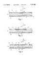
- FIG. 1is a schematic longitudinal cross-sectional view of an apparatus of the invention having a fluidic conduit comprising two channels and a linear passage. A detector is shown coaxially positioned with the linear passage.
- FIG. 2is a schematic longitudinal cross-sectional view of an apparatus of the invention having a fluidic conduit comprising three channels and two linear passages. A detector is shown coaxially positioned with the linear passage.
- FIG. 3is a schematic longitudinal cross-sectional view of an apparatus of the invention having a fluidic conduit comprising three channels disposed on the first and third substrates and two linear passages disposed within the second substrate. A detector is shown coaxially positioned with the linear passage.
- FIG. 4is a perspective view of an apparatus fabricated to contain a plurality of fluidic conduits.
- FIG. 4also depicts the excitation of the sample contained within each of the plurality of linear passages with fluorescent light focused transversely through the sample in the direction of the dotted arrow. Detectors are shown coaxially positioned with each linear passage, such detectors will be useful for detecting the light emitted by fluorescently excited sample constituents.
- the inventionprovides an apparatus, a method of manufacturing the apparatus and methods of detecting an analyte using the apparatus.
- the apparatus of the inventioncomprises a substrate containing the microfabricated channel system.
- the apparatuscan be fabricated from silicon and other solid substrates using established micromachining methods, or by molding polymeric materials, including polystyrene, polyacrylate and polycarbonate.
- the substrate, or the middle substrate of a stacked three substrate apparatusis preferably at least about 50 microns thick, and can be about 5000 microns thick or greater. More preferably, the substrate is about 400 microns to about 2000 microns thick.
- a cover, or the first and third substrates of a three substrate apparatusis typically an optically transparent material, or a material which has optically transparent portions in the area enclosing the junction of a channel to the transecting linear passage.
- Suitable optically transparent materialsinclude glass, fused silica, and sapphire.
- a materialwill be at least about 10 microns thick and can be several thousand microns thick (about 5000 microns) depending upon the design of the apparatus.
- a cover, or the first and third substrateswill be about 400 microns to 1000 microns thick.
- a covermay also comprise a sealant layer which is deposited upon the surface of the substrate after microfabrication of the conduit.
- the microfabricated conduitcould be filled with a removable material, e.g., a water or oil based liquid, the sealant layer applied to the substrate surface and then the material in the conduit removed.
- the channels and linear passagehave preferred internal dimensions of between about 0.1 microns and about 1000 microns.
- the channel widthsare more preferably between about 10 microns and about 1000 microns.
- the channel depthsare more preferably between about 5 microns and about 100 microns.
- the linear passagepreferably has an inner diameter of about 5 microns to about 1000 microns.
- the channels and linear passage in cross-section taken through the thickness of the substratemay be triangular, truncated conical, square, rectangular, circular, or any other shape.
- the fluidic conduits of the apparatustypically are designed on a scale suitable to analyze microvolumes ( ⁇ about 5 ⁇ l) of sample introduced into the flow system through an inlet port defined, e.g., by a hole communicating with the flow system through the substrate or through a cover. Analyte present in very low concentrations (e.g., approximately nanogram quantities) in microvolumes of a sample fluid can be rapidly analyzed (e.g., ⁇ about 10 minutes).
- the apparatuscan be formed by microfabricating each channel and linear passage in a single substrate and then enclosing the channels and linear passage with covers or by any other suitable means for sealing the fluidic conduit.
- the apparatusalso can be formed from three stacked substrates which are sandwiched together. In such an apparatus the first and second substrates define the first channel (and any non-contiguous third channel), the second substrate defines the linear passage(s), and the second and third substrates define the second channel.
- the first substratemay also contain holes or ports for providing access to the channel(s) when required.
- either of the first or second substrate, or second and third substratescan substantially define the channel and the other substrate can substantially enclose the channel.
- a channelmay also be distributed between each of the substrates such that a percentage of the channel is defined by each of the substrates when sandwiched together.
- the term “substantially define a channel”is used herein to designate that a channel has been microfabricated on the surface of the substrate.
- the term “substantially enclose a channel”is used herein to designate that the substrate is primarily acting to seal, or cover, the channel which has been microfabricated on the opposing substrate.
- FIGS. 1 and 2the apparatus is described as a single substrate the channels and linear passage(s) of which are enclosed by covers.
- the described channel configurationsalso can be accomplished by the formation of an apparatus composed of three substrates which have been sandwiched together.
- FIG. 3the apparatus is described as formed from three substrates which have been sandwiched together.
- the passageshave been microfabricated in the second substrate and the channels have been microfabricated on the first and third substrates. Assembly of the substrates into a sandwich results in enclosing the channels and formation of the complete fluidic conduit through the three substrates.
- the apparatusmay include a substrate 10 microfabricated with a fluidic conduit, comprising channels 12, 14 on either side of the substrate and a linear passage 28 which connects the channels through the substrate, and covers 20, 22 which enclose the fluidic conduit.
- a port 24,can be provided through a hole in the cover 20, or alternatively, as an opening 26, where the substrate 10 and the cover 22 end.
- An optical detector 40is positioned in the central axis of the linear passage, shown as dotted line 42, to measure the optical properties of an analyte within the linear passage 28.
- the length and depth of each channel and linear passage, and the size of each port or openingis shown using an expanded scale in the figures in order to distinctly depict the features of the apparatus.
- the second channel 14may be missing entirely or may be significantly shorter than the first channel.
- the second channelneed only be of sufficient length such that the sample is directed away from the linear passage. This allows an accurate optical measurement to be made of any analyte which is within the linear passage. Structures other than a second channel may also be used to direct the sample away from the linear passage.
- the apparatuscan be mounted at an angle to the horizontal plane such that the force of gravity will cause the sample to drain away from the linear passage.
- the apparatusmay include a substrate 10 microfabricated with a fluidic conduit, comprising non-contiguous channels 12, 16 disposed on one side of the substrate and channel 14 disposed on the opposite side of the substrate.
- Linear passage 18connects the first channel 12 with the second channel 14 and linear passage 28 connects the second channel 14 with the third channel 16.
- ports 24can be provided in the cover 20 which encloses the first channel 12 and the third channel 16.
- An optical detector 40is positioned in the central axis of the linear passage, shown as dotted line 42, to measure the optical properties of an analyte within the linear passage 28.
- the apparatusmay comprise a fluidic conduit in which a substrate 110 having linear passages 118, 128, and substrates 120, 122 having channels 112, 114, 116 are sealed together into a sandwich. Ports 124 may be provided in substrate 120 to allow access to the first channel 112 and third channel 116.
- An optical detector 40is positioned coaxially with the central axis of the linear passage, shown as dotted line 42, to measure the optical properties of an analyte within the linear passage 128.
- the apparatus of the inventionalso can be microfabricated such that at least one channel is disposed on substrate 110 and an additional channel or channels are disposed substrates 120 and 122, as discussed above.
- Optical detection of analytes within the linear passagecan be accomplished by positioning a detector at either end of the linear passage. Positioning of the detector at an end of the long central axis of the linear passage provides for a long optical path length, which greatly improves the sensitivity of detection of an analyte present in the fluidic conduit. Importantly, the design of linear passage results in an increased volume of sample which is measured by optical detection without compromising the resolving capability of the fluidic conduit.
- FIG. 4shows an apparatus with multiple fluidic conduits comprised of channels 12, 14, 16 each of which is configured for long path length detection through the central axis of a linear passage 18 or 28.
- Each fluidic conduitis provided with ports 24 for accessing the enclosed channels.
- FIG. 4also shows the apparatus of the invention used for fluorescence detection.
- the excitation lightemitted from a fluorescent light emitter 50, enters through the edge of the substrate 10, which necessarily must be transparent, and illuminates each linear passage 28 in a plurality of fluidic conduits.
- An optical detector 40is positioned coaxially with each linear passage 28 such that the detector 40 can detect the emission from the sample within the linear passages 28.
- the emission from an analytecan be measured using a detector positioned at either side of the microfabricated channel system, relative to the central axis 42 of the linear passage 28.
- the configuration of the apparatusprovides both a long optical path length, the linear passage 28, and also provides for orthogonality of the direction of excitation and emission which is desirable from the point of view of minimizing scatter of the excitation light in the direction in which emitted light is measured.
- the apparatus of the invention having a single or multiple fluidic conduitscan be designed and fabricated in large quantities from a solid substrate material. They also can be easily sterilized. Silicon is a preferred substrate material because of the well-developed technology permitting its precise and efficient fabrication, but other materials may be used including glass, fused silica and cast or molded organic polymers, including polystyrene, polyacrylate, and polycarbonate.
- the channels, linear passage(s) and other functional elements, such as a sample inlet or ports,may be fabricated inexpensively from a silicon substrate by any of a variety of micromachining methods known to those skilled in the art.
- micromachining methodsinclude film deposition processes such as spin coating and chemical vapor deposition, laser fabrication or photolithographic techniques such as UV or X-ray processes, or etching methods which may be performed by either wet chemical processes or plasma processes. (See, e.g., Manz et al., Trends in Analytical Chemistry, 10: 144-149 (1991)). Microfabricated channels of varying widths and depths can be fabricated for use in the apparatus.
- an apparatus having the design depicted in FIG. 2is manufactured using the following steps. Both positive and negative photoresist techniques are equally useful, and the following example briefly describes the use of a positive photoresist technique.
- a fused silica substrateis first coated with a 450 angstrom thick layer of chrome on each side by sputtering or evaporation. Photoresist is spun onto both sides of the substrate.
- a photomaskwhich provides the template for the two non-contiguous channels, is placed against the first surface of the substrate. The photomask covered substrate is then exposed to UV light, which causes a chemical reaction in the exposed photoresist and renders the exposed photoresist sensitive to photoresist developer.
- a photomask which provides the template for the single channelis placed against the second surface and the photomask covered substrate is exposed to UV light.
- the substrateis then placed in photoresist developer which dissolves the UV reacted photoresist and exposes the underlying chrome layer.
- the developed substrateis then placed in a bath of chrome etchant which dissolves the chrome where the photoresist has been removed and exposes the surface of the substrate.
- the substrateis then placed in a bath of buffered hydrofluoric acid, which etches the exposed substrate.
- the chrome layerallows deeper etching of the substrate than if photoresist alone is employed and also serves to prevent exposure of the photoresist on one side of the substrate by UV light transmitted through the substrate during the exposure of the other side.
- the etchingis isotropic thus resulting in etching in a direction under the remaining chrome and photoresist, and the formation of channels which are wider than they are deep.
- the use of silicon, quartz or other crystalline substratecan result in the formation of channels having a more nearly equal aspect ratio of depth and width.
- a hole(the linear passage) is formed through the substrate connecting the channels on opposite surfaces.
- the holecan be formed by techniques that allow precise micron sized holes to be machined. Laser drilling is one such technique. Micro sand blasting or a very small water jet are other techniques for making small holes that may serve this purpose.
- the channels on the opposing surfacesmust be in close registration in order for the linear passage to effectively connect the channels. Close registration can be achieved by careful production of paired photomasks for either surface of the substrate and uniform treatment of each side of the substrate during UV exposure, photoresist developing, and etching.
- channelscan be etched on separate covers using the method described above and the linear passage can be microfabricated in the substrate.
- the three componentscan be aligned to register the linear passage(s) with the channels and the components sealed together to form the apparatus having a fluidic conduit.
- non-transparent substratesit may be advantageous to form channels on one side of the substrate and then form the through hole.
- the through holecan then be used to register the channels to be formed on the other side, either lithographically or by laser ablation.
- One advantage of a non-transparent substrateis that the optical detection region formed by the through hole is self masking (i.e. light can only pass through the hole).
- a substrate containing microfabricated channels and linear passage(s)may be covered and sealed, e.g., anodically bonded, with a thin glass cover.
- Other clear or opaque cover materialsmay be used, and the cover need only be clear in the region covering the linear passage.
- a maskcould be provided in a transparent substrate by depositing and patterning an opaque material on the cover layer.
- An apparatuswhich is a sandwich of three stacked substrates can be sealed into a unit by any available technique, i.e. anodic bonding.
- the middle substrate of the apparatuscan be any suitable material as described above, and selection of a non-optically transparent material will result in self-masking the linear passage.
- the outer two substratescan be completely optically transparent and need to only incorporate optically transparent portions in the region on either side of the linear passage.
- the second substrateis composed of silicon, fused silica or glass.
- Optically transparent first and third substratesare provided which are composed of fused silica or glass. These materials can be thermally bonded together without the use of adhesives or sealants. The bonding process involves thorough cleaning of the substrates, bringing the pieces into contact in a clean environment (low in particulates), and elevating the temperature to cause bond formation. A potential can be applied to the pieces, after bringing them into contact, in order to encourage bonding.
- the first second and third substratesare composed of fused silica.
- the substratesare cleaned and activated in dilute NH 4 OH/H 2 O 2 solution and then transferred to a bath of filtered, deionized water where they are brought into contact. Once in contact, the pieces are removed from the bath and placed into an oven. The temperature is raised at 0.2° C./min. to 200° C. and held for at least 4 hours to drive out residual water. Thereafter the joined pieces are placed in a furnace. The temperature is raised at 2° C./min. to 200° C., held for 2 hours and then raised at 2° C./min. to 1000° C. and held for 6 hours. The furnace is then turned off and allowed to cool to room temperature. This method yields assemblies with substrates and covers bonded into an integrated unit.
- the capacity of the fluidic conduits in the apparatusis very small, and therefore the amount of fluid required for an analysis is low.
- the volume of each fluidic conduitis 10 -3 ⁇ l.
- the total volume of 500 of such fluidic conduits, which could be arrayed on a single substrate,is 0.5 ⁇ l.
- the low volume of the fluidic conduitsallows assays to be performed on very small amounts of a liquid sample ( ⁇ 0.5 ⁇ l).
- the fluidic conduitsmay be fabricated with microliter volumes, or alternatively with nanoliter volumes or less, which advantageously limits the amount of sample, buffer or other fluids required for an analysis.
- sample or reactant volumesmay be introduced by any of the methods employed in capillary electrophoretic and chromatography systems, including hydrodynamic, electrokinetic, vacuum, injection port, and syringe methods. Furthermore, the systems can be readily automated for injection with commercially available autoinjectors.
- the apparatuscan be used in combination with an appliance for delivering and receiving fluids to and from the apparatus which incorporates a nesting site for holding the apparatus and mates an input port on the apparatus with a flow line in the appliance, thus facilitating automation of sample analysis.
- the apparatuswill be disposed in an appliance in a horizontal plane, samples will be delivered to an inlet, a force (e.g., electric field, a pump, or capillary action) will be utilized to transport the sample through the channels and linear passage, and an optical detector will be situated to detect the presence of an analyte as it passes through a linear passage.
- a forcee.g., electric field, a pump, or capillary action
- the apparatusmay be disposed, e.g., in an appliance, at an angle with respect to a horizontal plane, to provide an incline for the travel of the sample fluid away from the exit of the linear passage without the disposition of a second channel upon the second surface of the substrate. Placement of such an apparatus at an angle with respect to the horizontal plane would allow clear detection through the linear passage by an optical detector without the need for a second channel or a second cover.
- a detection methodmay be chosen which allows for detection of any physical property of a chemical species.
- Preferred detection methodsinclude, but are not limited to, absorbance of infrared, ultraviolet or visible light radiation, chemiluminescence and fluorescence. Detection of analytes which have been separated by electrophoresis, supercritical fluid chromatography, or liquid chromatography may occur at a discrete position along the length of the channel, preferably by imaging along the axis of the linear passage of the apparatus.
- Use of optical detectors to detect analytes in the linear passageare compatible for use in combination with detectors which operate by directly sensing separated sample constituents as they exit the apparatus. Examples of such detectors which detect analytes after exit from the fluidic conduit include mass spectrometric detectors and electrochemical detectors.
- analyteis intended to mean any substance susceptible to optical detection using the instant apparatus, and any substance which can be bound to one or more binding partners which render the complex detectable by optical detection in the instant apparatus.
- a "binding partner”, as used herein,is any biochemical or chemical moiety which has an ability to interact specifically with, and bind with, a corresponding analyte.
- preferred analytes and binding partnersinclude chemical and biochemical moieties.
- analytes and binding partners suitable for analysis in the instant inventioninclude, but are not limited to, the following biochemical and chemical moieties: proteins, peptides, nucleic acids, peptide hormones, non-peptide hormones, drugs of abuse, environmental pollutants, pharmaceuticals, microbial antigens, viral antigens, carbohydrates, polyclonal antibodies, monoclonal antibodies, anti-idiotypic antibodies, antibody fragments, enzyme substrates, enzyme inhibitors, biotin, and receptors.
- biochemical or chemical substanceswhich can be rendered amenable to complex formation, i.e., can be manipulated or modified to bind with at least one binding partner or two different binding partners, are considered suitable for detection in the instant apparatus.
- sampleis intended to mean any specimen to be analyzed for an analyte of interest.
- samples for analysisinclude, but are not limited to, any biological or environmental specimen suspected to contain an analyte of interest.
- the instant apparatusis suitable for detection of analytes in samples of body fluids including, but not limited to: blood, serum, plasma, urine, cerebrospinal fluid, saliva, sweat, semen, vaginal fluid, amniotic fluid, and ascites fluid.
- body fluidsincluding, but not limited to: blood, serum, plasma, urine, cerebrospinal fluid, saliva, sweat, semen, vaginal fluid, amniotic fluid, and ascites fluid.
- analytes which are environmental pollutantsthey can be detected in fluids such as, but not limited to, rain water, ocean water, and sewer water.
- the inventionmay be embodied in other specific forms.
Landscapes
- Physics & Mathematics (AREA)
- Health & Medical Sciences (AREA)
- Life Sciences & Earth Sciences (AREA)
- Chemical & Material Sciences (AREA)
- Analytical Chemistry (AREA)
- Biochemistry (AREA)
- General Health & Medical Sciences (AREA)
- General Physics & Mathematics (AREA)
- Immunology (AREA)
- Pathology (AREA)
- Automatic Analysis And Handling Materials Therefor (AREA)
- Investigating, Analyzing Materials By Fluorescence Or Luminescence (AREA)
Abstract
Description
Claims (39)
Priority Applications (1)
| Application Number | Priority Date | Filing Date | Title |
|---|---|---|---|
| US08/425,290US5757482A (en) | 1995-04-20 | 1995-04-20 | Module for optical detection in microscale fluidic analyses |
Applications Claiming Priority (1)
| Application Number | Priority Date | Filing Date | Title |
|---|---|---|---|
| US08/425,290US5757482A (en) | 1995-04-20 | 1995-04-20 | Module for optical detection in microscale fluidic analyses |
Publications (1)
| Publication Number | Publication Date |
|---|---|
| US5757482Atrue US5757482A (en) | 1998-05-26 |
Family
ID=23685930
Family Applications (1)
| Application Number | Title | Priority Date | Filing Date |
|---|---|---|---|
| US08/425,290Expired - LifetimeUS5757482A (en) | 1995-04-20 | 1995-04-20 | Module for optical detection in microscale fluidic analyses |
Country Status (1)
| Country | Link |
|---|---|
| US (1) | US5757482A (en) |
Cited By (74)
| Publication number | Priority date | Publication date | Assignee | Title |
|---|---|---|---|---|
| WO2000009985A3 (en)* | 1998-08-14 | 2000-05-18 | Top Source Technologies Inc | On-site analyzer |
| US6143152A (en)* | 1997-11-07 | 2000-11-07 | The Regents Of The University Of California | Microfabricated capillary array electrophoresis device and method |
| US6150180A (en)* | 1996-06-28 | 2000-11-21 | Caliper Technologies Corp. | High throughput screening assay systems in microscale fluidic devices |
| US6193647B1 (en) | 1999-04-08 | 2001-02-27 | The Board Of Trustees Of The University Of Illinois | Microfluidic embryo and/or oocyte handling device and method |
| US6221654B1 (en) | 1996-09-25 | 2001-04-24 | California Institute Of Technology | Method and apparatus for analysis and sorting of polynucleotides based on size |
| US6224830B1 (en) | 1998-01-30 | 2001-05-01 | The Governors Of The University Of Alberta | Absorbance cell for microfluid devices |
| US6290685B1 (en) | 1998-06-18 | 2001-09-18 | 3M Innovative Properties Company | Microchanneled active fluid transport devices |
| US20020005354A1 (en)* | 1997-09-23 | 2002-01-17 | California Institute Of Technology | Microfabricated cell sorter |
| US20020012926A1 (en)* | 2000-03-03 | 2002-01-31 | Mycometrix, Inc. | Combinatorial array for nucleic acid analysis |
| US6375871B1 (en) | 1998-06-18 | 2002-04-23 | 3M Innovative Properties Company | Methods of manufacturing microfluidic articles |
| US20020100714A1 (en)* | 2001-01-31 | 2002-08-01 | Sau Lan Tang Staats | Microfluidic devices |
| US20020187074A1 (en)* | 2001-06-07 | 2002-12-12 | Nanostream, Inc. | Microfluidic analytical devices and methods |
| US20020197733A1 (en)* | 2001-06-20 | 2002-12-26 | Coventor, Inc. | Microfluidic system including a virtual wall fluid interface port for interfacing fluids with the microfluidic system |
| US20030015425A1 (en)* | 2001-06-20 | 2003-01-23 | Coventor Inc. | Microfluidic system including a virtual wall fluid interface port for interfacing fluids with the microfluidic system |
| US6540895B1 (en) | 1997-09-23 | 2003-04-01 | California Institute Of Technology | Microfabricated cell sorter for chemical and biological materials |
| US20030082632A1 (en)* | 2001-10-25 | 2003-05-01 | Cytoprint, Inc. | Assay method and apparatus |
| US20030138829A1 (en)* | 2001-11-30 | 2003-07-24 | Fluidigm Corp. | Microfluidic device and methods of using same |
| US20030171696A1 (en)* | 2002-03-05 | 2003-09-11 | Bayer Healthcare, Llc | Minimum invasive optical format with integrated lance |
| US6660213B1 (en)* | 1998-07-27 | 2003-12-09 | Fujitsu Limited | Nozzle plate manufacturing method |
| US20040018115A1 (en)* | 2002-07-29 | 2004-01-29 | Nanostream, Inc. | Fault tolerant detection regions in microfluidic systems |
| US20040072278A1 (en)* | 2002-04-01 | 2004-04-15 | Fluidigm Corporation | Microfluidic particle-analysis systems |
| US20040091398A1 (en)* | 2001-06-20 | 2004-05-13 | Teragenics, Inc. | Microfluidic system including a virtual wall fluid interface port for interfacing fluids with the microfluidic system |
| RU2229699C2 (en)* | 2000-05-04 | 2004-05-27 | Зимина Татьяна Михайловна | Analytical capillary microchip |
| US6752914B1 (en)* | 1998-03-12 | 2004-06-22 | Deltadot Limited | Capillary electrophoresis device |
| US20040118189A1 (en)* | 2002-10-31 | 2004-06-24 | Nanostream, Inc. | Pressurized microfluidic devices with optical detection regions |
| US20040248167A1 (en)* | 2000-06-05 | 2004-12-09 | Quake Stephen R. | Integrated active flux microfluidic devices and methods |
| US6839179B2 (en) | 2002-05-10 | 2005-01-04 | Applera Corporation | Imaging system and method for reduction of interstitial images |
| US20050006729A1 (en)* | 2002-05-03 | 2005-01-13 | Hoag David Russell | Method of making heterojunction P-I-N diode |
| US20050019792A1 (en)* | 2001-11-30 | 2005-01-27 | Fluidigm Corporation | Microfluidic device and methods of using same |
| US6867857B2 (en) | 2002-10-29 | 2005-03-15 | Nanostream, Inc. | Flow cell for optical analysis of a fluid |
| US20050065735A1 (en)* | 2000-06-27 | 2005-03-24 | Fluidigm Corporation | Microfluidic design automation method and system |
| US20050123947A1 (en)* | 1997-09-23 | 2005-06-09 | California Institute Of Technology | Methods and systems for molecular fingerprinting |
| US20050129581A1 (en)* | 2003-04-03 | 2005-06-16 | Fluidigm Corporation | Microfluidic devices and methods of using same |
| US20050145496A1 (en)* | 2003-04-03 | 2005-07-07 | Federico Goodsaid | Thermal reaction device and method for using the same |
| US20050196785A1 (en)* | 2001-03-05 | 2005-09-08 | California Institute Of Technology | Combinational array for nucleic acid analysis |
| US20050252773A1 (en)* | 2003-04-03 | 2005-11-17 | Fluidigm Corporation | Thermal reaction device and method for using the same |
| US6969850B2 (en) | 2001-12-19 | 2005-11-29 | Sau Lan Tang Staats | Microfluidic array devices and methods of manufacturing and uses thereof |
| US20050284213A1 (en)* | 2004-06-29 | 2005-12-29 | Nanostream, Inc. | Sealing interface for microfluidic device |
| US20060094004A1 (en)* | 2004-10-28 | 2006-05-04 | Akihisa Nakajima | Micro-reactor, biological material inspection device, and microanalysis system |
| US20060099116A1 (en)* | 2000-10-13 | 2006-05-11 | Mycometrix Corporation | Microfluidic-based electrospray source for analytical devices |
| US7050660B2 (en) | 2003-04-07 | 2006-05-23 | Eksigent Technologies Llc | Microfluidic detection device having reduced dispersion and method for making same |
| US7069952B1 (en) | 2001-11-14 | 2006-07-04 | Caliper Life Sciences, Inc. | Microfluidic devices and methods of their manufacture |
| US20060263264A1 (en)* | 2001-06-20 | 2006-11-23 | Cytonome, Inc | Microfluidic system including a virtual wall fluid interface port for interfacing fluids with the microfluidic system |
| KR100703889B1 (en) | 2003-12-29 | 2007-04-05 | 전자부품연구원 | Device for solution component analysis and its manufacturing method |
| US7223364B1 (en) | 1999-07-07 | 2007-05-29 | 3M Innovative Properties Company | Detection article having fluid control film |
| US20070217953A1 (en)* | 2006-03-16 | 2007-09-20 | Brennen Reid A | Optical detection cell with micro-fluidic chip |
| US20070218454A1 (en)* | 2006-03-16 | 2007-09-20 | Brennen Reid A | Optical detection cell for micro-fluidics |
| US20080084559A1 (en)* | 2006-10-10 | 2008-04-10 | C Technologies, Inc. | Microvolume sampling device |
| US7413712B2 (en) | 2003-08-11 | 2008-08-19 | California Institute Of Technology | Microfluidic rotary flow reactor matrix |
| US7476363B2 (en) | 2003-04-03 | 2009-01-13 | Fluidigm Corporation | Microfluidic devices and methods of using same |
| US20090153851A1 (en)* | 2007-11-13 | 2009-06-18 | Herfried Huemer | Cuvette and method for using the cuvette |
| US20090262343A1 (en)* | 2008-04-18 | 2009-10-22 | Archibald William B | Infrared spectroscopy of media, including aqueous |
| US20090323069A1 (en)* | 2006-07-20 | 2009-12-31 | Kris Naessens | Optical characterisation methods and systems |
| US7670559B2 (en) | 2001-02-15 | 2010-03-02 | Caliper Life Sciences, Inc. | Microfluidic systems with enhanced detection systems |
| CN101738336A (en)* | 2008-11-12 | 2010-06-16 | 霍夫曼-拉罗奇有限公司 | Hemolyser |
| US20100234674A1 (en)* | 2009-01-05 | 2010-09-16 | Wheeler Matthew B | Microfluidic systems and methods |
| US7833708B2 (en) | 2001-04-06 | 2010-11-16 | California Institute Of Technology | Nucleic acid amplification using microfluidic devices |
| US20100327182A1 (en)* | 2008-02-14 | 2010-12-30 | Starna Scientific Limited | Fluorescence measurement cell |
| US8440093B1 (en) | 2001-10-26 | 2013-05-14 | Fuidigm Corporation | Methods and devices for electronic and magnetic sensing of the contents of microfluidic flow channels |
| US20130186187A1 (en)* | 2010-10-04 | 2013-07-25 | King Saud University | Nanoflow detector cell |
| US20130196360A1 (en)* | 2012-01-26 | 2013-08-01 | Samsung Electronics Co., Ltd. | Microfluidic device and control method thereof |
| WO2013174862A1 (en)* | 2012-05-24 | 2013-11-28 | Leica Microsystems Cms Gmbh | Specimen collector for collecting a laser micro-dissectate |
| US8658418B2 (en) | 2002-04-01 | 2014-02-25 | Fluidigm Corporation | Microfluidic particle-analysis systems |
| US8828663B2 (en) | 2005-03-18 | 2014-09-09 | Fluidigm Corporation | Thermal reaction device and method for using the same |
| US8871446B2 (en) | 2002-10-02 | 2014-10-28 | California Institute Of Technology | Microfluidic nucleic acid analysis |
| EP2851683A2 (en) | 2002-02-01 | 2015-03-25 | Perseptive Biosystems, Inc. | Capillary column chromatography process and system |
| US20150283512A1 (en)* | 2014-04-03 | 2015-10-08 | New York University | Microfabricated ion-selective filter for filtration of ions and molecules |
| US9714443B2 (en) | 2002-09-25 | 2017-07-25 | California Institute Of Technology | Microfabricated structure having parallel and orthogonal flow channels controlled by row and column multiplexors |
| US10509018B2 (en) | 2000-11-16 | 2019-12-17 | California Institute Of Technology | Apparatus and methods for conducting assays and high throughput screening |
| US20200249146A1 (en)* | 2019-02-04 | 2020-08-06 | Shimadzu Corporation | Flow cell |
| US11075019B2 (en)* | 2014-10-23 | 2021-07-27 | The University Of Hull | System for radiopharmaceutical production |
| US11369955B2 (en) | 2014-10-23 | 2022-06-28 | The University Of Hull | Method and apparatus for the analysis of compounds |
| US11559785B2 (en) | 2014-10-23 | 2023-01-24 | The University Of Hull | Method for separation of radioactive sample using monolithic body on microfluidic chip |
| US20240085336A1 (en)* | 2015-09-30 | 2024-03-14 | Sigma Additive Solutions, Inc. | Systems and methods for additive manufacturing operations |
Citations (14)
| Publication number | Priority date | Publication date | Assignee | Title |
|---|---|---|---|---|
| US4823168A (en)* | 1986-11-07 | 1989-04-18 | Hitachi, Ltd. | Flow-through cell for a photometer formed using a pair of cell body members |
| US5006210A (en)* | 1989-02-06 | 1991-04-09 | Iowa State University Research Foundation, Inc. | Means and method for capillary zone electrophoresis with laser-induced indirect fluorescence detection |
| US5057216A (en)* | 1989-04-14 | 1991-10-15 | Kontron Instruments Holding Nv | Capillary flow cell |
| US5061361A (en)* | 1989-03-06 | 1991-10-29 | Hewlett-Packard Company | Capillary zone electrophoresis cell system |
| US5092973A (en)* | 1990-01-26 | 1992-03-03 | The Board Of Trustees Of The Leland Stanford Junior University | Rectangular capillaries for capillary electrophoresis |
| US5194915A (en)* | 1990-09-20 | 1993-03-16 | Millipore Corporation | Photometric apparatus and process |
| US5228969A (en)* | 1989-06-21 | 1993-07-20 | Europhor Sa | Capillary electrophoresis apparatus including a capillary tube having an incorporated optical device |
| US5235409A (en)* | 1991-08-13 | 1993-08-10 | Varian Associates, Inc. | Optical detection system for capillary separation columns |
| US5273633A (en)* | 1992-07-10 | 1993-12-28 | Tiansong Wang | Capillary multireflective cell |
| US5303021A (en)* | 1990-12-28 | 1994-04-12 | Shimadzu Corporation | Optical detector for capillary chromatography |
| US5318686A (en)* | 1992-11-13 | 1994-06-07 | Bio-Rad Laboratories, Inc. | Capillary aligning device for on-line optical detection |
| US5326973A (en)* | 1992-01-03 | 1994-07-05 | Artema Medical Ab | Device for gas analysis |
| EP0616211A1 (en)* | 1993-03-18 | 1994-09-21 | Ciba-Geigy Ag | Optical detection arrangement for small volume chemical analysis of fluid samples |
| US5493405A (en)* | 1993-07-19 | 1996-02-20 | Optiglass Limited | Spectrophotometer cell having an intermediate wall member and an integral lens |
- 1995
- 1995-04-20USUS08/425,290patent/US5757482A/ennot_activeExpired - Lifetime
Patent Citations (15)
| Publication number | Priority date | Publication date | Assignee | Title |
|---|---|---|---|---|
| US5141548A (en)* | 1986-04-14 | 1992-08-25 | Kontron Instruments Holding Nv | Method of manufacturing a capillary flow cell |
| US4823168A (en)* | 1986-11-07 | 1989-04-18 | Hitachi, Ltd. | Flow-through cell for a photometer formed using a pair of cell body members |
| US5006210A (en)* | 1989-02-06 | 1991-04-09 | Iowa State University Research Foundation, Inc. | Means and method for capillary zone electrophoresis with laser-induced indirect fluorescence detection |
| US5061361A (en)* | 1989-03-06 | 1991-10-29 | Hewlett-Packard Company | Capillary zone electrophoresis cell system |
| US5057216A (en)* | 1989-04-14 | 1991-10-15 | Kontron Instruments Holding Nv | Capillary flow cell |
| US5228969A (en)* | 1989-06-21 | 1993-07-20 | Europhor Sa | Capillary electrophoresis apparatus including a capillary tube having an incorporated optical device |
| US5092973A (en)* | 1990-01-26 | 1992-03-03 | The Board Of Trustees Of The Leland Stanford Junior University | Rectangular capillaries for capillary electrophoresis |
| US5194915A (en)* | 1990-09-20 | 1993-03-16 | Millipore Corporation | Photometric apparatus and process |
| US5303021A (en)* | 1990-12-28 | 1994-04-12 | Shimadzu Corporation | Optical detector for capillary chromatography |
| US5235409A (en)* | 1991-08-13 | 1993-08-10 | Varian Associates, Inc. | Optical detection system for capillary separation columns |
| US5326973A (en)* | 1992-01-03 | 1994-07-05 | Artema Medical Ab | Device for gas analysis |
| US5273633A (en)* | 1992-07-10 | 1993-12-28 | Tiansong Wang | Capillary multireflective cell |
| US5318686A (en)* | 1992-11-13 | 1994-06-07 | Bio-Rad Laboratories, Inc. | Capillary aligning device for on-line optical detection |
| EP0616211A1 (en)* | 1993-03-18 | 1994-09-21 | Ciba-Geigy Ag | Optical detection arrangement for small volume chemical analysis of fluid samples |
| US5493405A (en)* | 1993-07-19 | 1996-02-20 | Optiglass Limited | Spectrophotometer cell having an intermediate wall member and an integral lens |
Non-Patent Citations (4)
| Title |
|---|
| Mesaros et al., "Continuous Electrophoretic Separations in Narrow Channels Coupled to Small-Bore Capillaries", Anal. Chem., 65:3313-3319 (1993). |
| Mesaros et al., Continuous Electrophoretic Separations in Narrow Channels Coupled to Small Bore Capillaries , Anal. Chem ., 65:3313 3319 (1993).* |
| Sobek et al "A Microfabricated Flow Chamber for Optical Measurements in Fluids". Proceedings of IEEE Micro Electro Mechanical Systems, Fort Lauderdale, Fl, Feb. 7, 1993, pp. 219-224. |
| Sobek et al A Microfabricated Flow Chamber for Optical Measurements in Fluids . Proceedings of IEEE Micro Electro Mechanical Systems, Fort Lauderdale, Fl, Feb. 7, 1993, pp. 219 224.* |
Cited By (159)
| Publication number | Priority date | Publication date | Assignee | Title |
|---|---|---|---|---|
| US6150180A (en)* | 1996-06-28 | 2000-11-21 | Caliper Technologies Corp. | High throughput screening assay systems in microscale fluidic devices |
| US7670471B2 (en) | 1996-09-25 | 2010-03-02 | California Institute Of Technology | Method and apparatus for analysis and sorting of polynucleotides based on size |
| US8388822B2 (en) | 1996-09-25 | 2013-03-05 | California Institute Of Technology | Method and apparatus for analysis and sorting of polynucleotides based on size |
| US6964736B2 (en) | 1996-09-25 | 2005-11-15 | California Institute Of Technology | Method and apparatus for analysis and sorting of polynucleotides based on size |
| US6221654B1 (en) | 1996-09-25 | 2001-04-24 | California Institute Of Technology | Method and apparatus for analysis and sorting of polynucleotides based on size |
| US9383337B2 (en) | 1996-09-25 | 2016-07-05 | California Institute Of Technology | Method and apparatus for analysis and sorting of polynucleotides based on size |
| US8173001B2 (en) | 1996-09-25 | 2012-05-08 | California Institute Of Technology | Method and apparatus for analysis and sorting of polynucleotides based on size |
| US20060035273A1 (en)* | 1996-09-25 | 2006-02-16 | California Institute Of Technology | Method and apparatus for analysis and sorting of polynucleotides based on size |
| US20100171954A1 (en)* | 1996-09-25 | 2010-07-08 | California Institute Of Technology | Method and Apparatus for Analysis and Sorting of Polynucleotides Based on Size |
| US6344325B1 (en) | 1996-09-25 | 2002-02-05 | California Institute Of Technology | Methods for analysis and sorting of polynucleotides |
| US20050123947A1 (en)* | 1997-09-23 | 2005-06-09 | California Institute Of Technology | Methods and systems for molecular fingerprinting |
| US20020005354A1 (en)* | 1997-09-23 | 2002-01-17 | California Institute Of Technology | Microfabricated cell sorter |
| US20110229872A1 (en)* | 1997-09-23 | 2011-09-22 | California Institute Of Technology | Microfabricated Cell Sorter |
| US7214298B2 (en) | 1997-09-23 | 2007-05-08 | California Institute Of Technology | Microfabricated cell sorter |
| US6540895B1 (en) | 1997-09-23 | 2003-04-01 | California Institute Of Technology | Microfabricated cell sorter for chemical and biological materials |
| US6143152A (en)* | 1997-11-07 | 2000-11-07 | The Regents Of The University Of California | Microfabricated capillary array electrophoresis device and method |
| US6749734B1 (en) | 1997-11-07 | 2004-06-15 | The Regents Of The University Of California | Microfabricated capillary array electrophoresis device and method |
| US6224830B1 (en) | 1998-01-30 | 2001-05-01 | The Governors Of The University Of Alberta | Absorbance cell for microfluid devices |
| US6752914B1 (en)* | 1998-03-12 | 2004-06-22 | Deltadot Limited | Capillary electrophoresis device |
| US6375871B1 (en) | 1998-06-18 | 2002-04-23 | 3M Innovative Properties Company | Methods of manufacturing microfluidic articles |
| US6761962B2 (en) | 1998-06-18 | 2004-07-13 | 3M Innovative Properties Company | Microfluidic articles |
| US6290685B1 (en) | 1998-06-18 | 2001-09-18 | 3M Innovative Properties Company | Microchanneled active fluid transport devices |
| US6660213B1 (en)* | 1998-07-27 | 2003-12-09 | Fujitsu Limited | Nozzle plate manufacturing method |
| AU2003257512B2 (en)* | 1998-08-14 | 2004-07-22 | Spectro Scientific, Inc. | On-site analyzer |
| AU763570B2 (en)* | 1998-08-14 | 2003-07-24 | Spectro Scientific, Inc. | On-site analyzer |
| WO2000009985A3 (en)* | 1998-08-14 | 2000-05-18 | Top Source Technologies Inc | On-site analyzer |
| US6452179B1 (en) | 1998-08-14 | 2002-09-17 | Global Technovations, Inc. | On-site analyzer |
| US6707043B2 (en) | 1998-08-14 | 2004-03-16 | On-Site Analysis, Inc. | On-site analyzer |
| US6695765B1 (en) | 1999-04-08 | 2004-02-24 | The Board Of Trustees Of The University Of Illinois | Microfluidic channel embryo and/or oocyte handling, analysis and biological evaluation |
| US6193647B1 (en) | 1999-04-08 | 2001-02-27 | The Board Of Trustees Of The University Of Illinois | Microfluidic embryo and/or oocyte handling device and method |
| US7223364B1 (en) | 1999-07-07 | 2007-05-29 | 3M Innovative Properties Company | Detection article having fluid control film |
| US8197775B2 (en) | 1999-07-07 | 2012-06-12 | 3M Innovative Properties Company | Detection article having fluid control film |
| US20020012926A1 (en)* | 2000-03-03 | 2002-01-31 | Mycometrix, Inc. | Combinatorial array for nucleic acid analysis |
| RU2229699C2 (en)* | 2000-05-04 | 2004-05-27 | Зимина Татьяна Михайловна | Analytical capillary microchip |
| US7622081B2 (en) | 2000-06-05 | 2009-11-24 | California Institute Of Technology | Integrated active flux microfluidic devices and methods |
| US20040248167A1 (en)* | 2000-06-05 | 2004-12-09 | Quake Stephen R. | Integrated active flux microfluidic devices and methods |
| US7351376B1 (en) | 2000-06-05 | 2008-04-01 | California Institute Of Technology | Integrated active flux microfluidic devices and methods |
| US20100120018A1 (en)* | 2000-06-05 | 2010-05-13 | California Institute Of Technology | Integrated Active Flux Microfluidic Devices and Methods |
| US8129176B2 (en) | 2000-06-05 | 2012-03-06 | California Institute Of Technology | Integrated active flux microfluidic devices and methods |
| US8257666B2 (en) | 2000-06-05 | 2012-09-04 | California Institute Of Technology | Integrated active flux microfluidic devices and methods |
| US7526741B2 (en) | 2000-06-27 | 2009-04-28 | Fluidigm Corporation | Microfluidic design automation method and system |
| US9926521B2 (en) | 2000-06-27 | 2018-03-27 | Fluidigm Corporation | Microfluidic particle-analysis systems |
| US20050065735A1 (en)* | 2000-06-27 | 2005-03-24 | Fluidigm Corporation | Microfluidic design automation method and system |
| US20060099116A1 (en)* | 2000-10-13 | 2006-05-11 | Mycometrix Corporation | Microfluidic-based electrospray source for analytical devices |
| US7442556B2 (en) | 2000-10-13 | 2008-10-28 | Fluidigm Corporation | Microfluidic-based electrospray source for analytical devices with a rotary fluid flow channel for sample preparation |
| US10509018B2 (en) | 2000-11-16 | 2019-12-17 | California Institute Of Technology | Apparatus and methods for conducting assays and high throughput screening |
| EP1343973B2 (en)† | 2000-11-16 | 2020-09-16 | California Institute Of Technology | Apparatus and methods for conducting assays and high throughput screening |
| US20020100714A1 (en)* | 2001-01-31 | 2002-08-01 | Sau Lan Tang Staats | Microfluidic devices |
| US7670559B2 (en) | 2001-02-15 | 2010-03-02 | Caliper Life Sciences, Inc. | Microfluidic systems with enhanced detection systems |
| US20050196785A1 (en)* | 2001-03-05 | 2005-09-08 | California Institute Of Technology | Combinational array for nucleic acid analysis |
| US8486636B2 (en) | 2001-04-06 | 2013-07-16 | California Institute Of Technology | Nucleic acid amplification using microfluidic devices |
| US8936764B2 (en) | 2001-04-06 | 2015-01-20 | California Institute Of Technology | Nucleic acid amplification using microfluidic devices |
| US7833708B2 (en) | 2001-04-06 | 2010-11-16 | California Institute Of Technology | Nucleic acid amplification using microfluidic devices |
| US20020187074A1 (en)* | 2001-06-07 | 2002-12-12 | Nanostream, Inc. | Microfluidic analytical devices and methods |
| US6919046B2 (en) | 2001-06-07 | 2005-07-19 | Nanostream, Inc. | Microfluidic analytical devices and methods |
| US20030015425A1 (en)* | 2001-06-20 | 2003-01-23 | Coventor Inc. | Microfluidic system including a virtual wall fluid interface port for interfacing fluids with the microfluidic system |
| US20060263264A1 (en)* | 2001-06-20 | 2006-11-23 | Cytonome, Inc | Microfluidic system including a virtual wall fluid interface port for interfacing fluids with the microfluidic system |
| US20020197733A1 (en)* | 2001-06-20 | 2002-12-26 | Coventor, Inc. | Microfluidic system including a virtual wall fluid interface port for interfacing fluids with the microfluidic system |
| US7179423B2 (en) | 2001-06-20 | 2007-02-20 | Cytonome, Inc. | Microfluidic system including a virtual wall fluid interface port for interfacing fluids with the microfluidic system |
| US7211442B2 (en) | 2001-06-20 | 2007-05-01 | Cytonome, Inc. | Microfluidic system including a virtual wall fluid interface port for interfacing fluids with the microfluidic system |
| US20040091398A1 (en)* | 2001-06-20 | 2004-05-13 | Teragenics, Inc. | Microfluidic system including a virtual wall fluid interface port for interfacing fluids with the microfluidic system |
| US20070148777A1 (en)* | 2001-06-20 | 2007-06-28 | Cytonome, Inc. | Microfluidic system including a virtual wall fluid interface port for interfacing fluids with the microfluidic system |
| US20030082632A1 (en)* | 2001-10-25 | 2003-05-01 | Cytoprint, Inc. | Assay method and apparatus |
| US8845914B2 (en) | 2001-10-26 | 2014-09-30 | Fluidigm Corporation | Methods and devices for electronic sensing |
| US9103761B2 (en) | 2001-10-26 | 2015-08-11 | Fluidigm Corporation | Methods and devices for electronic sensing |
| US8440093B1 (en) | 2001-10-26 | 2013-05-14 | Fuidigm Corporation | Methods and devices for electronic and magnetic sensing of the contents of microfluidic flow channels |
| US7069952B1 (en) | 2001-11-14 | 2006-07-04 | Caliper Life Sciences, Inc. | Microfluidic devices and methods of their manufacture |
| US8343442B2 (en) | 2001-11-30 | 2013-01-01 | Fluidigm Corporation | Microfluidic device and methods of using same |
| US7118910B2 (en) | 2001-11-30 | 2006-10-10 | Fluidigm Corporation | Microfluidic device and methods of using same |
| US7837946B2 (en) | 2001-11-30 | 2010-11-23 | Fluidigm Corporation | Microfluidic device and methods of using same |
| US20030138829A1 (en)* | 2001-11-30 | 2003-07-24 | Fluidigm Corp. | Microfluidic device and methods of using same |
| US7820427B2 (en) | 2001-11-30 | 2010-10-26 | Fluidigm Corporation | Microfluidic device and methods of using same |
| US8163492B2 (en) | 2001-11-30 | 2012-04-24 | Fluidign Corporation | Microfluidic device and methods of using same |
| US7691333B2 (en) | 2001-11-30 | 2010-04-06 | Fluidigm Corporation | Microfluidic device and methods of using same |
| US9643178B2 (en) | 2001-11-30 | 2017-05-09 | Fluidigm Corporation | Microfluidic device with reaction sites configured for blind filling |
| US20070004031A1 (en)* | 2001-11-30 | 2007-01-04 | Fluidigm Corporation | Microfluidic device and methods of using same |
| US20070004033A1 (en)* | 2001-11-30 | 2007-01-04 | Fluidigm Corporation | Microfluidic device and methods of using same |
| US20050019792A1 (en)* | 2001-11-30 | 2005-01-27 | Fluidigm Corporation | Microfluidic device and methods of using same |
| US6969850B2 (en) | 2001-12-19 | 2005-11-29 | Sau Lan Tang Staats | Microfluidic array devices and methods of manufacturing and uses thereof |
| EP2851683A2 (en) | 2002-02-01 | 2015-03-25 | Perseptive Biosystems, Inc. | Capillary column chromatography process and system |
| US20030171696A1 (en)* | 2002-03-05 | 2003-09-11 | Bayer Healthcare, Llc | Minimum invasive optical format with integrated lance |
| US20060258958A1 (en)* | 2002-03-05 | 2006-11-16 | Dosmann Andrew J | Minimum invasive optical format with integrated lance |
| US20040072278A1 (en)* | 2002-04-01 | 2004-04-15 | Fluidigm Corporation | Microfluidic particle-analysis systems |
| US7452726B2 (en) | 2002-04-01 | 2008-11-18 | Fluidigm Corporation | Microfluidic particle-analysis systems |
| US20040224380A1 (en)* | 2002-04-01 | 2004-11-11 | Fluidigm Corp. | Microfluidic particle-analysis systems |
| US7312085B2 (en) | 2002-04-01 | 2007-12-25 | Fluidigm Corporation | Microfluidic particle-analysis systems |
| US8658418B2 (en) | 2002-04-01 | 2014-02-25 | Fluidigm Corporation | Microfluidic particle-analysis systems |
| US20050006729A1 (en)* | 2002-05-03 | 2005-01-13 | Hoag David Russell | Method of making heterojunction P-I-N diode |
| US6839179B2 (en) | 2002-05-10 | 2005-01-04 | Applera Corporation | Imaging system and method for reduction of interstitial images |
| US20050128598A1 (en)* | 2002-05-10 | 2005-06-16 | Applera Corporation | Imaging system and method for reduction of interstitial images |
| US20040018115A1 (en)* | 2002-07-29 | 2004-01-29 | Nanostream, Inc. | Fault tolerant detection regions in microfluidic systems |
| US9714443B2 (en) | 2002-09-25 | 2017-07-25 | California Institute Of Technology | Microfabricated structure having parallel and orthogonal flow channels controlled by row and column multiplexors |
| US8871446B2 (en) | 2002-10-02 | 2014-10-28 | California Institute Of Technology | Microfluidic nucleic acid analysis |
| US9579650B2 (en) | 2002-10-02 | 2017-02-28 | California Institute Of Technology | Microfluidic nucleic acid analysis |
| US10328428B2 (en) | 2002-10-02 | 2019-06-25 | California Institute Of Technology | Apparatus for preparing cDNA libraries from single cells |
| US10940473B2 (en) | 2002-10-02 | 2021-03-09 | California Institute Of Technology | Microfluidic nucleic acid analysis |
| US6867857B2 (en) | 2002-10-29 | 2005-03-15 | Nanostream, Inc. | Flow cell for optical analysis of a fluid |
| US20040118189A1 (en)* | 2002-10-31 | 2004-06-24 | Nanostream, Inc. | Pressurized microfluidic devices with optical detection regions |
| US7010964B2 (en) | 2002-10-31 | 2006-03-14 | Nanostream, Inc. | Pressurized microfluidic devices with optical detection regions |
| US7666361B2 (en) | 2003-04-03 | 2010-02-23 | Fluidigm Corporation | Microfluidic devices and methods of using same |
| US20050252773A1 (en)* | 2003-04-03 | 2005-11-17 | Fluidigm Corporation | Thermal reaction device and method for using the same |
| US20090142236A1 (en)* | 2003-04-03 | 2009-06-04 | Fluidigm Corporation | Microfluidic Devices and Methods of Using Same |
| US7749737B2 (en) | 2003-04-03 | 2010-07-06 | Fluidigm Corporation | Thermal reaction device and method for using the same |
| US9150913B2 (en) | 2003-04-03 | 2015-10-06 | Fluidigm Corporation | Thermal reaction device and method for using the same |
| US7867454B2 (en) | 2003-04-03 | 2011-01-11 | Fluidigm Corporation | Thermal reaction device and method for using the same |
| US20090061428A1 (en)* | 2003-04-03 | 2009-03-05 | Fluidigm Corporation | Thermal Reaction Device and Method for Using the Same |
| US7476363B2 (en) | 2003-04-03 | 2009-01-13 | Fluidigm Corporation | Microfluidic devices and methods of using same |
| US7604965B2 (en) | 2003-04-03 | 2009-10-20 | Fluidigm Corporation | Thermal reaction device and method for using the same |
| US8007746B2 (en) | 2003-04-03 | 2011-08-30 | Fluidigm Corporation | Microfluidic devices and methods of using same |
| US20050129581A1 (en)* | 2003-04-03 | 2005-06-16 | Fluidigm Corporation | Microfluidic devices and methods of using same |
| US8247178B2 (en) | 2003-04-03 | 2012-08-21 | Fluidigm Corporation | Thermal reaction device and method for using the same |
| US20050145496A1 (en)* | 2003-04-03 | 2005-07-07 | Federico Goodsaid | Thermal reaction device and method for using the same |
| US10131934B2 (en) | 2003-04-03 | 2018-11-20 | Fluidigm Corporation | Thermal reaction device and method for using the same |
| US7050660B2 (en) | 2003-04-07 | 2006-05-23 | Eksigent Technologies Llc | Microfluidic detection device having reduced dispersion and method for making same |
| US7925125B2 (en) | 2003-04-07 | 2011-04-12 | Dh Technologies Development Pte. Ltd. | Microfluidic detection device having reduced dispersion and method for making same |
| US7336860B2 (en) | 2003-04-07 | 2008-02-26 | Eksigent Technologies, Llc | Microfluidic detection device having reduced dispersion and method for making same |
| US20080216951A1 (en)* | 2003-04-07 | 2008-09-11 | Cyr Douglas R | Microfluidic Detection Device Having Reduced Dispersion And Method For Making Same |
| US20070104408A1 (en)* | 2003-04-07 | 2007-05-10 | Cyr Douglas R | Microfluidic detection device having reduced dispersion and method for making same |
| US20090087356A1 (en)* | 2003-08-11 | 2009-04-02 | California Institute Of Technology | Microfluidic Rotary Flow Reactor Matrix |
| US7413712B2 (en) | 2003-08-11 | 2008-08-19 | California Institute Of Technology | Microfluidic rotary flow reactor matrix |
| US20100104477A1 (en)* | 2003-08-11 | 2010-04-29 | California Institute Of Technology | Microfluidic rotary flow reactor matrix |
| US7964139B2 (en) | 2003-08-11 | 2011-06-21 | California Institute Of Technology | Microfluidic rotary flow reactor matrix |
| KR100703889B1 (en) | 2003-12-29 | 2007-04-05 | 전자부품연구원 | Device for solution component analysis and its manufacturing method |
| US20050284213A1 (en)* | 2004-06-29 | 2005-12-29 | Nanostream, Inc. | Sealing interface for microfluidic device |
| US7028536B2 (en) | 2004-06-29 | 2006-04-18 | Nanostream, Inc. | Sealing interface for microfluidic device |
| US20060094004A1 (en)* | 2004-10-28 | 2006-05-04 | Akihisa Nakajima | Micro-reactor, biological material inspection device, and microanalysis system |
| US8828663B2 (en) | 2005-03-18 | 2014-09-09 | Fluidigm Corporation | Thermal reaction device and method for using the same |
| US20070218454A1 (en)* | 2006-03-16 | 2007-09-20 | Brennen Reid A | Optical detection cell for micro-fluidics |
| US20070217953A1 (en)* | 2006-03-16 | 2007-09-20 | Brennen Reid A | Optical detection cell with micro-fluidic chip |
| US8647590B2 (en) | 2006-03-16 | 2014-02-11 | Agilent Technologies, Inc. | Optical detection cell with micro-fluidic chip |
| US20090323069A1 (en)* | 2006-07-20 | 2009-12-31 | Kris Naessens | Optical characterisation methods and systems |
| US8064063B2 (en)* | 2006-07-20 | 2011-11-22 | Trinean Nv | Optical characterisation methods and systems |
| US20080084559A1 (en)* | 2006-10-10 | 2008-04-10 | C Technologies, Inc. | Microvolume sampling device |
| US7948619B2 (en)* | 2007-11-13 | 2011-05-24 | Roche Diagnostics Operations, Inc. | Cuvette and method for using the cuvette |
| US20090153851A1 (en)* | 2007-11-13 | 2009-06-18 | Herfried Huemer | Cuvette and method for using the cuvette |
| US8357916B2 (en)* | 2008-02-14 | 2013-01-22 | Starna Scientific Limited | Fluorescence measurement cell |
| US20100327182A1 (en)* | 2008-02-14 | 2010-12-30 | Starna Scientific Limited | Fluorescence measurement cell |
| US20090262343A1 (en)* | 2008-04-18 | 2009-10-22 | Archibald William B | Infrared spectroscopy of media, including aqueous |
| CN101738336A (en)* | 2008-11-12 | 2010-06-16 | 霍夫曼-拉罗奇有限公司 | Hemolyser |
| US8279433B2 (en)* | 2008-11-12 | 2012-10-02 | Roche Diagnostics Operating, Inc. | Haemolysator |
| US20100151512A1 (en)* | 2008-11-12 | 2010-06-17 | Roche Diagnostics Operations, Inc. | Haemolysator |
| US9157550B2 (en) | 2009-01-05 | 2015-10-13 | The Board Of Trustees Of The University Of Illinois | Microfluidic systems and methods |
| US20100234674A1 (en)* | 2009-01-05 | 2010-09-16 | Wheeler Matthew B | Microfluidic systems and methods |
| US9217732B2 (en)* | 2010-10-04 | 2015-12-22 | King Saud University | Nanoflow detector cell |
| US20130186187A1 (en)* | 2010-10-04 | 2013-07-25 | King Saud University | Nanoflow detector cell |
| US20130196360A1 (en)* | 2012-01-26 | 2013-08-01 | Samsung Electronics Co., Ltd. | Microfluidic device and control method thereof |
| US9719894B2 (en) | 2012-05-24 | 2017-08-01 | Leica Microsystems Cms Gmbh | Specimen collector for collecting a laser micro-dissectate |
| WO2013174862A1 (en)* | 2012-05-24 | 2013-11-28 | Leica Microsystems Cms Gmbh | Specimen collector for collecting a laser micro-dissectate |
| US9956529B2 (en)* | 2014-04-03 | 2018-05-01 | New York University | Microfabricated ion-selective filter for filtration of ions and molecules |
| US20150283512A1 (en)* | 2014-04-03 | 2015-10-08 | New York University | Microfabricated ion-selective filter for filtration of ions and molecules |
| US11369955B2 (en) | 2014-10-23 | 2022-06-28 | The University Of Hull | Method and apparatus for the analysis of compounds |
| US11559785B2 (en) | 2014-10-23 | 2023-01-24 | The University Of Hull | Method for separation of radioactive sample using monolithic body on microfluidic chip |
| US11075019B2 (en)* | 2014-10-23 | 2021-07-27 | The University Of Hull | System for radiopharmaceutical production |
| US20240085336A1 (en)* | 2015-09-30 | 2024-03-14 | Sigma Additive Solutions, Inc. | Systems and methods for additive manufacturing operations |
| US12019026B2 (en)* | 2015-09-30 | 2024-06-25 | Divergent Technologies, Inc. | Systems and methods for additive manufacturing operations |
| US20240302286A1 (en)* | 2015-09-30 | 2024-09-12 | Divergent Technologies, Inc. | Systems and methods for additive manufacturing operations |
| US12292384B2 (en)* | 2015-09-30 | 2025-05-06 | Divergent Technologies, Inc. | Systems and methods for additive manufacturing operations |
| US10739249B1 (en)* | 2019-02-04 | 2020-08-11 | Shimadzu Corporation | Flow cell |
| US20200249146A1 (en)* | 2019-02-04 | 2020-08-06 | Shimadzu Corporation | Flow cell |
Similar Documents
| Publication | Publication Date | Title |
|---|---|---|
| US5757482A (en) | Module for optical detection in microscale fluidic analyses | |
| US7258837B2 (en) | Microfluidic device and surface decoration process for solid phase affinity binding assays | |
| US6979424B2 (en) | Integrated sample analysis device | |
| US7105354B1 (en) | Analyzer | |
| AU2002329526B2 (en) | Microfluidic chemical assay apparatus and method | |
| US6534013B1 (en) | Microfluidic devices and systems | |
| US5972710A (en) | Microfabricated diffusion-based chemical sensor | |
| US6251343B1 (en) | Microfluidic devices and systems incorporating cover layers | |
| US6534011B1 (en) | Device for detecting biochemical or chemical substances by fluorescence excitation | |
| US6406604B1 (en) | Multi-dimensional electrophoresis apparatus | |
| EP1064090B1 (en) | Device for analyzing a sample | |
| US20060073599A1 (en) | Microfabricated diffusion-based chemical sensor | |
| US20060141469A1 (en) | Multi-layered electrochemical microfluidic sensor comprising reagent on porous layer | |
| WO1997039338A9 (en) | Microfabricated diffusion-based chemical sensor | |
| AU2002329526A1 (en) | Microfluidic chemical assay apparatus and method | |
| CA2301592A1 (en) | Capillary electroflow apparatus and method | |
| AU764319B2 (en) | Chemical processing device | |
| Sabbagh et al. | Enhancing commercially available immunoassays through a customized electrokinetic biomolecular preconcentration device | |
| WO2004005924A1 (en) | 3d microarray | |
| Cheng | Exploring design and detection issues for automated multichannel microfluidic immunoassay system | |
| Coltro et al. | REAL-TIME MONITORING OF BINDING ASSAYS ON MICROFLUIDIC DEVICES WITH CONTACTLESS CONDUCTIVITY DETECTION | |
| SUGUMAR et al. | Lab-Cd |
Legal Events
| Date | Code | Title | Description |
|---|---|---|---|
| AS | Assignment | Owner name:PERSEPTIVE BIOSYSTEMS, INC., MASSACHUSETTS Free format text:ASSIGNMENT OF ASSIGNORS INTEREST;ASSIGNORS:FUCHS, MARTIN;KOUTNY, LANCE BRYANT;REEL/FRAME:007550/0164 Effective date:19950418 | |
| STCF | Information on status: patent grant | Free format text:PATENTED CASE | |
| FEPP | Fee payment procedure | Free format text:PAYOR NUMBER ASSIGNED (ORIGINAL EVENT CODE: ASPN); ENTITY STATUS OF PATENT OWNER: LARGE ENTITY | |
| FPAY | Fee payment | Year of fee payment:4 | |
| FPAY | Fee payment | Year of fee payment:8 | |
| AS | Assignment | Owner name:BANK OF AMERICA, N.A., AS COLLATERAL AGENT, WASHIN Free format text:SECURITY AGREEMENT;ASSIGNOR:PERSEPTIVE BIOSYSTEMS, INC.;REEL/FRAME:021976/0160 Effective date:20081121 | |
| FPAY | Fee payment | Year of fee payment:12 | |
| AS | Assignment | Owner name:APPLIED BIOSYSTEMS, INC., CALIFORNIA Free format text:LIEN RELEASE;ASSIGNOR:BANK OF AMERICA, N.A.;REEL/FRAME:030182/0677 Effective date:20100528 | |
| AS | Assignment | Owner name:APPLIED BIOSYSTEMS, LLC, CALIFORNIA Free format text:MERGER;ASSIGNOR:PERSEPTIVE BIOSYSTEMS, INC.;REEL/FRAME:031907/0696 Effective date:20090407 | |
| AS | Assignment | Owner name:APPLIED BIOSYSTEMS, LLC, CALIFORNIA Free format text:CORRECTIVE ASSIGNMENT TO CORRECT THE RECEIVING PARTY NAME PREVIOUSLY RECORDED AT REEL: 030182 FRAME: 0718. ASSIGNOR(S) HEREBY CONFIRMS THE RELEASE OF SECURITY INTEREST;ASSIGNOR:BANK OF AMERICA, N.A.;REEL/FRAME:038038/0134 Effective date:20100528 Owner name:APPLIED BIOSYSTEMS, LLC, CALIFORNIA Free format text:CORRECTIVE ASSIGNMENT TO CORRECT THE RECEIVING PARTY NAME PREVIOUSLY RECORDED AT REEL: 030182 FRAME: 0677. ASSIGNOR(S) HEREBY CONFIRMS THE RELEASE OF SECURITY INTEREST;ASSIGNOR:BANK OF AMERICA, N.A.;REEL/FRAME:038038/0134 Effective date:20100528 |