US5755722A - Stent placement device with medication dispenser and method - Google Patents
Stent placement device with medication dispenser and methodDownload PDFInfo
- Publication number
- US5755722A US5755722AUS08/361,963US36196394AUS5755722AUS 5755722 AUS5755722 AUS 5755722AUS 36196394 AUS36196394 AUS 36196394AUS 5755722 AUS5755722 AUS 5755722A
- Authority
- US
- United States
- Prior art keywords
- balloon
- stent
- conduits
- inflation
- diameter
- Prior art date
- Legal status (The legal status is an assumption and is not a legal conclusion. Google has not performed a legal analysis and makes no representation as to the accuracy of the status listed.)
- Expired - Lifetime
Links
Images
Classifications
- A—HUMAN NECESSITIES
- A61—MEDICAL OR VETERINARY SCIENCE; HYGIENE
- A61F—FILTERS IMPLANTABLE INTO BLOOD VESSELS; PROSTHESES; DEVICES PROVIDING PATENCY TO, OR PREVENTING COLLAPSING OF, TUBULAR STRUCTURES OF THE BODY, e.g. STENTS; ORTHOPAEDIC, NURSING OR CONTRACEPTIVE DEVICES; FOMENTATION; TREATMENT OR PROTECTION OF EYES OR EARS; BANDAGES, DRESSINGS OR ABSORBENT PADS; FIRST-AID KITS
- A61F2/00—Filters implantable into blood vessels; Prostheses, i.e. artificial substitutes or replacements for parts of the body; Appliances for connecting them with the body; Devices providing patency to, or preventing collapsing of, tubular structures of the body, e.g. stents
- A61F2/95—Instruments specially adapted for placement or removal of stents or stent-grafts
- A61F2/958—Inflatable balloons for placing stents or stent-grafts
- A—HUMAN NECESSITIES
- A61—MEDICAL OR VETERINARY SCIENCE; HYGIENE
- A61M—DEVICES FOR INTRODUCING MEDIA INTO, OR ONTO, THE BODY; DEVICES FOR TRANSDUCING BODY MEDIA OR FOR TAKING MEDIA FROM THE BODY; DEVICES FOR PRODUCING OR ENDING SLEEP OR STUPOR
- A61M25/00—Catheters; Hollow probes
- A61M25/0021—Catheters; Hollow probes characterised by the form of the tubing
- A61M25/0023—Catheters; Hollow probes characterised by the form of the tubing by the form of the lumen, e.g. cross-section, variable diameter
- A—HUMAN NECESSITIES
- A61—MEDICAL OR VETERINARY SCIENCE; HYGIENE
- A61M—DEVICES FOR INTRODUCING MEDIA INTO, OR ONTO, THE BODY; DEVICES FOR TRANSDUCING BODY MEDIA OR FOR TAKING MEDIA FROM THE BODY; DEVICES FOR PRODUCING OR ENDING SLEEP OR STUPOR
- A61M25/00—Catheters; Hollow probes
- A61M25/10—Balloon catheters
- A61M25/1027—Making of balloon catheters
- A61M25/1029—Production methods of the balloon members, e.g. blow-moulding, extruding, deposition or by wrapping a plurality of layers of balloon material around a mandril
- A—HUMAN NECESSITIES
- A61—MEDICAL OR VETERINARY SCIENCE; HYGIENE
- A61F—FILTERS IMPLANTABLE INTO BLOOD VESSELS; PROSTHESES; DEVICES PROVIDING PATENCY TO, OR PREVENTING COLLAPSING OF, TUBULAR STRUCTURES OF THE BODY, e.g. STENTS; ORTHOPAEDIC, NURSING OR CONTRACEPTIVE DEVICES; FOMENTATION; TREATMENT OR PROTECTION OF EYES OR EARS; BANDAGES, DRESSINGS OR ABSORBENT PADS; FIRST-AID KITS
- A61F2250/00—Special features of prostheses classified in groups A61F2/00 - A61F2/26 or A61F2/82 or A61F9/00 or A61F11/00 or subgroups thereof
- A61F2250/0058—Additional features; Implant or prostheses properties not otherwise provided for
- A61F2250/0067—Means for introducing or releasing pharmaceutical products into the body
- A—HUMAN NECESSITIES
- A61—MEDICAL OR VETERINARY SCIENCE; HYGIENE
- A61M—DEVICES FOR INTRODUCING MEDIA INTO, OR ONTO, THE BODY; DEVICES FOR TRANSDUCING BODY MEDIA OR FOR TAKING MEDIA FROM THE BODY; DEVICES FOR PRODUCING OR ENDING SLEEP OR STUPOR
- A61M25/00—Catheters; Hollow probes
- A61M25/0021—Catheters; Hollow probes characterised by the form of the tubing
- A61M25/0023—Catheters; Hollow probes characterised by the form of the tubing by the form of the lumen, e.g. cross-section, variable diameter
- A61M25/0026—Multi-lumen catheters with stationary elements
- A61M2025/0036—Multi-lumen catheters with stationary elements with more than four lumina
- A—HUMAN NECESSITIES
- A61—MEDICAL OR VETERINARY SCIENCE; HYGIENE
- A61M—DEVICES FOR INTRODUCING MEDIA INTO, OR ONTO, THE BODY; DEVICES FOR TRANSDUCING BODY MEDIA OR FOR TAKING MEDIA FROM THE BODY; DEVICES FOR PRODUCING OR ENDING SLEEP OR STUPOR
- A61M25/00—Catheters; Hollow probes
- A61M25/0021—Catheters; Hollow probes characterised by the form of the tubing
- A61M25/0023—Catheters; Hollow probes characterised by the form of the tubing by the form of the lumen, e.g. cross-section, variable diameter
- A61M25/0026—Multi-lumen catheters with stationary elements
- A61M2025/004—Multi-lumen catheters with stationary elements characterized by lumina being arranged circumferentially
- A—HUMAN NECESSITIES
- A61—MEDICAL OR VETERINARY SCIENCE; HYGIENE
- A61M—DEVICES FOR INTRODUCING MEDIA INTO, OR ONTO, THE BODY; DEVICES FOR TRANSDUCING BODY MEDIA OR FOR TAKING MEDIA FROM THE BODY; DEVICES FOR PRODUCING OR ENDING SLEEP OR STUPOR
- A61M25/00—Catheters; Hollow probes
- A61M25/10—Balloon catheters
- A61M2025/1043—Balloon catheters with special features or adapted for special applications
- A61M2025/105—Balloon catheters with special features or adapted for special applications having a balloon suitable for drug delivery, e.g. by using holes for delivery, drug coating or membranes
- A—HUMAN NECESSITIES
- A61—MEDICAL OR VETERINARY SCIENCE; HYGIENE
- A61M—DEVICES FOR INTRODUCING MEDIA INTO, OR ONTO, THE BODY; DEVICES FOR TRANSDUCING BODY MEDIA OR FOR TAKING MEDIA FROM THE BODY; DEVICES FOR PRODUCING OR ENDING SLEEP OR STUPOR
- A61M25/00—Catheters; Hollow probes
- A61M25/10—Balloon catheters
- A61M2025/1043—Balloon catheters with special features or adapted for special applications
- A61M2025/1086—Balloon catheters with special features or adapted for special applications having a special balloon surface topography, e.g. pores, protuberances, spikes or grooves
- A—HUMAN NECESSITIES
- A61—MEDICAL OR VETERINARY SCIENCE; HYGIENE
- A61M—DEVICES FOR INTRODUCING MEDIA INTO, OR ONTO, THE BODY; DEVICES FOR TRANSDUCING BODY MEDIA OR FOR TAKING MEDIA FROM THE BODY; DEVICES FOR PRODUCING OR ENDING SLEEP OR STUPOR
- A61M25/00—Catheters; Hollow probes
- A61M25/10—Balloon catheters
- A61M25/1018—Balloon inflating or inflation-control devices
- A61M25/10181—Means for forcing inflation fluid into the balloon
- A—HUMAN NECESSITIES
- A61—MEDICAL OR VETERINARY SCIENCE; HYGIENE
- A61M—DEVICES FOR INTRODUCING MEDIA INTO, OR ONTO, THE BODY; DEVICES FOR TRANSDUCING BODY MEDIA OR FOR TAKING MEDIA FROM THE BODY; DEVICES FOR PRODUCING OR ENDING SLEEP OR STUPOR
- A61M25/00—Catheters; Hollow probes
- A61M25/10—Balloon catheters
- A61M25/1027—Making of balloon catheters
Definitions
- the present inventionrelates to a medical device utilizing a balloon catheter for placement of an expandable intraluminal graft, commonly called a stent, within a body passageway such as an artery.
- a stentcan also be used for the placement of interluminal grafts such as aortic aneurism grafts.
- the inventionespecially relates to a medical device including a balloon catheter which can provide forcible expansion of the cross-section of an artery that has been narrowed by atherosclerotic lesion or stenosis and also simultaneously implant a stent at a predetermined site within the artery.
- the inventionfurther relates to a medical device including a balloon catheter and a method of operating it which can both implant a stent in body passageway and also dispense medication at a predetermined site within the passageway.
- a deviceincludes an inflatable balloon disposed at the end of multi-lumen catheter shaft in which a pressurizing fluid is forced into the balloon to expand it. The expansion of the balloon engages the surface of the artery to enlarge its cross-section.
- Balloon use for implantation of stentsis also well known to the art. With balloon implantation, the stent is placed on the balloon and the stent is located at a site the physician has decided to treat while viewing the procedure through X-rays. When in the correct location the balloon is deflated and withdrawn leaving the stent behind.
- a second balloon of larger diameteris placed inside the stent and the second balloon is expanded with a pressurizing fluid to a greater diameter and the stent expands further to engage the portion of the vessel being treated.
- location of the stent within the vesselis difficult because it requires two balloons and it is difficult to move the stent small distances to precisely locate it.
- using a large diameter balloon and partially inflating it for locating and then further enlarging it for implantationrequires a large profile (diameter) balloon and does not afford the same type of positive engagement between the exterior of the balloon and the stent to enable the physician to make fine adjustments in positioning.
- a stentis a tubular-shaped device that can be formed of a plurality of intersecting elongate members.
- the stent used hereinis an interwoven plexus of at least two sets of helically disposed wires wound together with one set juxtaposed relative to the other set to form a tubular arrangement expandable to a plurality of diameters.
- the devicehas a first diameter for interluminal delivery into a body passageway. It has a second expanded diameter for application (from the interior) of a radially outwardly extending force such as delivered by a balloon.
- the second diameter of the stentis variable and dependent upon the amount of force applied to urge it outwardly to expand the lumen of the body passageway.
- the stentalso has a third diameter for implantation, again by internal force, within the passageway.
- the balloonis expandable into more than one diameter and the stent is similarly expandable to more than one diameter, usually two balloons are used for the procedure, one for delivery and a larger one for implantation because a balloon large enough for implantation presents a profile that is wider than necessary for the procedure.
- an inflatable medical devicefor placement of a stent in a body passageway by means of a two-stage expansion of the stent on a single balloon.
- the deviceincludes a catheter shaft with at least two fluid handling lumens and a hollow inflatable balloon having a generally cylindrical wall on the end of the catheter shaft.
- the interior of the balloonis in fluid flow relation with one of the lumens to provide the interior of the balloon with an inflation fluid.
- An array of circumferentially arranged inflation conduitsis disposed within the wall of the balloon. These conduits are individually segmented and spaced from each other.
- a stentis disposed around the exterior of the wall of the balloon.
- the stentis expandable radially outwardly from a narrow insertion diameter to a larger second diameter by expansion of the balloon and then to a larger third diameter by inflation of the inflation conduits to expand the stent within the body passageway and implant it.
- one of the lumens of the two-inflation-lumen catheter shaftis used for dispensing medications from the conduits within the wall of the balloon.
- the conduitsare in fluid flow connection with the inflation lumen to dispense medications and also to inflate them.
- the catheter of the present inventiontwo dissimilar polymeric materials are co-extruded.
- One of the extrusionsforms a tube and the other extrusion (disposed as discrete segments within wall of the tube) forms a circumferentially arranged array of strands.
- the polymers we have found usefulare polyethylene terephthalate for the tube and polyethylene for the strands.
- the strandsare withdrawn from the tube to form conduits.
- the tubeis then expanded and the conduits are expanded also.
- Some, but not necessarily all, of the conduitscan be perforated to form medication dispensing conduits leaving the unperforated conduits as inflation conduits.
- the balloon and the conduitsare conventionally attached to a catheter shaft with lumens in fluid flow communication with inflatable portions of the balloon.
- the balloonis then wrapped conventionally and the stent, in its narrowest diameter, is placed around the wrapped balloon.
- the balloon on the catheter shaftis inflated to a first diameter through one of the inflation lumens to expand the stent to a first diameter and enable positioning of the stent and forcible expansion of the cross-section of the body passageway.
- the balloonis then expanded to a still larger diameter by forcing inflation fluid through another of the inflation lumens to inflate the inflation conduits thereby expanding the stent to an still larger diameter to enable seating and implantation of the stent within the body passageway.
- medicationscan be dispensed through perforations in some of the conduits disposed within the wall of the balloon. In either embodiment after implantation of the stent and the introduction of medications the balloon is withdrawn from within the stent which is now seated within the body passageway.
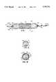
- FIG. 1is a side elevational view of an expanded medical balloon with an expanded stent disposed upon it.
- FIGS. 1A and 1Bare sectional views taken along the lines 1A--1A and 1B--1B respectively showing lumens of the catheter shaft and the attachment between the catheter shaft and the balloon.
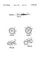
- FIG. 2is a side view of the balloon according to the present invention in a deflated and wrapped state and with a collapsed stent disposed about it.
- FIGS. 2A and 2Bare cross-sectional views taken along the line 2--2 of FIG. 1. In these views the balloon is expanded and the stent disposed about it is expanded also.
- FIGS. 2C and 2Dare views similar to the views of FIGS. 2A and 2B except in these views the inflation conduits are inflated also to fully expand the stent disposed around the balloon catheter for implantation. Uninflated conduits are used for dispensing medications.
- a balloon-type medical catheteris shown.
- the balloon-type catheter of the present inventionis similar to other catheters used for treating coronary artery disease except as otherwise shown and described.
- the catheterutilizes sleeves 27 and 27a to connect the balloon 16 to the catheter shaft 14.
- the sleeve 27is utilized for the transfer of inflation fluids and medications from lumens in the multiluminal tubing forming catheter shaft 14 to a medical balloon 16.
- the balloon 16is disposed at the distal end of the catheter shaft 14.
- Medical balloon 16is made of materials described herein and is heat-sealed or adhesively attached at its respective ends 16a and 16b to catheter shaft 14.
- inflation lumens 22 and 28are disposed within the catheter shaft 14.
- One of these inflation lumensis used to inflate the balloon 16 and the other is used to inflate the individual balloons constituting the array of circumferentially arranged inflation conduits 40.
- port 20provides communication between the interior of the balloon 16 and the lumen 22.
- a port(not shown) is cut in the inflation lumen 28 and disposed within the sleeve 27 to provide communication between inflation lumen 28 and the array of conduits 40 and 25 (shown in FIG. 2B and 2D).
- Lumen 28extends through the catheter shaft 14 and communicates with a fluid introduction port (not shown) at the proximal end of the shaft 14.
- Medications in fluid formcan also be introduced through lumen 28 provided within the catheter shaft 14 through the fluid introduction port (not shown) at the proximal end of the catheter shaft 14.
- the medication conduits 25can have perforations 21 disposed in the walls thereof.
- a third lumen 13extends completely through the catheter shaft 14 so a conventional guidewire 15 having a conventional exploratory tip 15a may be inserted in balloon 13 to assist catheter insertion in a body passageway in a conventional manner.
- the conduits 25 and 40are circumferentially arranged within the perimeter of wall of balloon 16.
- Each of the medication-dispensing conduits 25is provided with one or more perforations 21 to enable entry of medications into the body passageway that has been catheterized.
- these perforations 21can be helically-arranged around the perimeter of balloon 16 but any configuration that allows the introduction of medications can be used.
- the perforations 21are formed in the conduits 25 by inflating both the balloon 16 and the conduits 25 and then pricking each conduit wall lightly with a pin until it deflates.
- conduits 25can be pierced with laser irradiation.
- the perforations 21preferably have diameters in the range 0.0001 to 2.5 mm, depending upon the viscosity of the medication being dispensed, the desired flow rate and the conduit diameter.
- elongated slits on the outside of the conduitscan be used also, if required for the introduction of very viscous material or particulate material.
- the cross-sectional shape of the conduits 25is important only to the extent that they can receive the medications being dispensed. Conduits having square or rectangular sectional shapes are easy to make and will provide the necessary dispensing functions.
- An array of circumferentially-arranged inflation conduits 40is also disposed in the wall of the balloon 16.
- each inflation conduit 40is disposed between two medication dispensing conduits 25 and vice versa but such relationships need not be maintained so long as the inflation conduits 40 can expand the balloon sufficiently to seat the stent 30 in the body passageway.
- Each of the inflation conduits 40is in fluid flow relation with the inflation lumen 22 disposed in the shaft 14.
- Inflation of the balloon 16 through lumen 20 and port 28causes the balloon 16 to unwrap and form the generally cylindrical configuration shown in FIGS. 1 and 2A.
- the expansioncauses the proximal and distal ends of the balloon 16 to assume a generally conical shape.
- the profile of the balloon 16can approximate the diameter of the shaft 14 because extremely thin-walled balloons can be employed, as will be described hereinafter.
- FIGS. 1, 2A and 2Cthe balloon 16 is shown in an inflated state.
- Each of the medication dispensing conduits 25 and the inflation conduits 40are shown to share a common side wall 16d.
- the wall thicknesses of each wallcan be between about 0.0001 and 0.004 inches with 0.003 to 0.002 inches being preferred.
- the deflated profile of the balloon 16can be 0.003 inches or less.
- the interior of the balloon, that is the inner diameter of the balloon,can be between about 0.02 and 2.0 inches.
- the inflation conduits 40can have widths of between about 0.25 and 2.0 mm. Inflation conduits 40, as shown in FIG.
- 2Dcan double and even triple in width thus providing a significant increase in the diameter of the stent 30 that is disposed about it as will be discussed hereinafter.
- inflation conduitsarranged circumferentially within the wall of the balloon.
- a stent that has proven useful with the balloon catheter of the present inventionis a tubular-shaped member having first and second ends and a wall surface disposed between the first and second ends.
- the wall surfaceis formed of a plurality of intersecting elongate members some of which intersect with one another intermediate the first and second ends of the tubular member.
- the tubular-shaped memberhas a first diameter which permits delivery of the member into a body passageway.
- the tubular memberhas a second, expanded diameter which is formed upon the application from the interior of the tubular-shaped member of a radially outwardly extending force. The second diameter is variable and depends upon the amount of force applied to the tubular-shaped member so that the member can be expanded at an intraluminal site proposed for implantation.
- the tubular memberalso has a third diameter which is larger than the first and second diameters.
- the third diameteris used for the actual intraluminal implantation of the stent 30.
- the stent 30is formed of a plurality of wires with the wires fixedly secured to one another where they intersect each other.
- the elongated membersmay be a plurality of thin bars which are also fixedly secured to one another where they intersect.
- metalis most frequently used for the stent, polymeric materials formed in similar shapes can also be used. Polymeric materials have the advantage that certain compositions, as is well known, can be absorbed by the body so that after the stenosis is remedied they can disappear.
- the stent 30closely engages the balloon 16 when it is wrapped.
- the balloon 16is inflated (as shown in FIGS. 1 and 2A) the stent 30 will expand due to the radially outwardly extending force of the balloon.
- the individual members forming the stent 30will space themselves further apart.
- the stent 30, although expanded,can still be moved within the body passageway in which it is inserted. As a benefit this can allow the stent 30 to be moved back and forth for precise location.
- the inflation conduits 40are inflated and the diameter of the device will be enlarged further thereby enlarging the diameter of the stent 30 which surrounds it.
- the stentis then permanently implanted within the body passageway being treated.
- the balloon and the inflation conduitsare deflated.
- the balloon 16is withdrawn from within the stent and the catheter is removed from the body passageway.
- a 6 mm balloon(inflated diameter) can expand to 6.5 or 7.0 mm to expand the stent.
- the physiciancan even change medications from one used for preimplantation to a different one for post-implantation medication as desired.
Landscapes
- Health & Medical Sciences (AREA)
- Engineering & Computer Science (AREA)
- Life Sciences & Earth Sciences (AREA)
- Biomedical Technology (AREA)
- Heart & Thoracic Surgery (AREA)
- Animal Behavior & Ethology (AREA)
- Veterinary Medicine (AREA)
- Public Health (AREA)
- General Health & Medical Sciences (AREA)
- Anesthesiology (AREA)
- Biophysics (AREA)
- Pulmonology (AREA)
- Hematology (AREA)
- Vascular Medicine (AREA)
- Transplantation (AREA)
- Oral & Maxillofacial Surgery (AREA)
- Cardiology (AREA)
- Manufacturing & Machinery (AREA)
- Child & Adolescent Psychology (AREA)
- Media Introduction/Drainage Providing Device (AREA)
- Prostheses (AREA)
Abstract
Description
Claims (15)
Priority Applications (7)
| Application Number | Priority Date | Filing Date | Title |
|---|---|---|---|
| US08/361,963US5755722A (en) | 1994-12-22 | 1994-12-22 | Stent placement device with medication dispenser and method |
| PCT/US1995/016643WO1996019257A1 (en) | 1994-12-22 | 1995-12-21 | Stent placement device with medication dispenser and method |
| CA002206536ACA2206536C (en) | 1994-12-22 | 1995-12-21 | Stent placement device with medication dispenser and method |
| DE69532208TDE69532208T2 (en) | 1994-12-22 | 1995-12-21 | STENT INTRODUCTION DEVICE WITH MEDICAMENT DISPENSER AND METHOD OF MANUFACTURE |
| EP95944171AEP0799073B1 (en) | 1994-12-22 | 1995-12-21 | Stent placement device with medication dispenser and manufacturing method |
| JP51998796AJP3756185B2 (en) | 1994-12-22 | 1995-12-21 | Stent placement device with dosing device and method thereof |
| US08/999,175US5928247A (en) | 1994-12-22 | 1997-12-29 | Stent placement device with medication dispenser and method |
Applications Claiming Priority (1)
| Application Number | Priority Date | Filing Date | Title |
|---|---|---|---|
| US08/361,963US5755722A (en) | 1994-12-22 | 1994-12-22 | Stent placement device with medication dispenser and method |
Related Child Applications (1)
| Application Number | Title | Priority Date | Filing Date |
|---|---|---|---|
| US08/999,175DivisionUS5928247A (en) | 1994-12-22 | 1997-12-29 | Stent placement device with medication dispenser and method |
Publications (1)
| Publication Number | Publication Date |
|---|---|
| US5755722Atrue US5755722A (en) | 1998-05-26 |
Family
ID=23424125
Family Applications (2)
| Application Number | Title | Priority Date | Filing Date |
|---|---|---|---|
| US08/361,963Expired - LifetimeUS5755722A (en) | 1994-12-22 | 1994-12-22 | Stent placement device with medication dispenser and method |
| US08/999,175Expired - LifetimeUS5928247A (en) | 1994-12-22 | 1997-12-29 | Stent placement device with medication dispenser and method |
Family Applications After (1)
| Application Number | Title | Priority Date | Filing Date |
|---|---|---|---|
| US08/999,175Expired - LifetimeUS5928247A (en) | 1994-12-22 | 1997-12-29 | Stent placement device with medication dispenser and method |
Country Status (6)
| Country | Link |
|---|---|
| US (2) | US5755722A (en) |
| EP (1) | EP0799073B1 (en) |
| JP (1) | JP3756185B2 (en) |
| CA (1) | CA2206536C (en) |
| DE (1) | DE69532208T2 (en) |
| WO (1) | WO1996019257A1 (en) |
Cited By (32)
| Publication number | Priority date | Publication date | Assignee | Title |
|---|---|---|---|---|
| US5976181A (en)* | 1997-09-22 | 1999-11-02 | Ave Connaught | Balloon mounted stent and method therefor |
| US20020016597A1 (en)* | 2000-08-02 | 2002-02-07 | Dwyer Clifford J. | Delivery apparatus for a self-expanding stent |
| US6471968B1 (en) | 2000-05-12 | 2002-10-29 | Regents Of The University Of Michigan | Multifunctional nanodevice platform |
| US20040030377A1 (en)* | 2001-10-19 | 2004-02-12 | Alexander Dubson | Medicated polymer-coated stent assembly |
| US20040030218A1 (en)* | 2001-01-30 | 2004-02-12 | Scimed Life Systems, Inc. | Stent with channel(s) for containing and delivering biologically active material and method for manufacturing the same |
| US20040054406A1 (en)* | 2000-12-19 | 2004-03-18 | Alexander Dubson | Vascular prosthesis and method for production thereof |
| US20040094873A1 (en)* | 2001-03-20 | 2004-05-20 | Alexander Dubson | Portable electrospinning device |
| US6743219B1 (en) | 2000-08-02 | 2004-06-01 | Cordis Corporation | Delivery apparatus for a self-expanding stent |
| US7041139B2 (en) | 2001-12-11 | 2006-05-09 | Boston Scientific Scimed, Inc. | Ureteral stents and related methods |
| US20060259151A1 (en)* | 2005-05-11 | 2006-11-16 | Tim Ward | Ureteral stent with conforming retention structure |
| WO2007008829A2 (en) | 2005-07-08 | 2007-01-18 | C.R. Bard, Inc. | Drug delivery system |
| US7169170B2 (en) | 2002-02-22 | 2007-01-30 | Cordis Corporation | Self-expanding stent delivery system |
| US20070031607A1 (en)* | 2000-12-19 | 2007-02-08 | Alexander Dubson | Method and apparatus for coating medical implants |
| US20070041934A1 (en)* | 2005-08-12 | 2007-02-22 | Regents Of The University Of Michigan | Dendrimer based compositions and methods of using the same |
| US7244272B2 (en) | 2000-12-19 | 2007-07-17 | Nicast Ltd. | Vascular prosthesis and method for production thereof |
| US20080200975A1 (en)* | 2004-01-06 | 2008-08-21 | Nicast Ltd. | Vascular Prosthesis with Anastomotic Member |
| US20090088376A1 (en)* | 2007-04-19 | 2009-04-02 | The Regents Of The University Of Michigan | Dendrimer based compositions and methods of using the same |
| US20090099636A1 (en)* | 2007-10-10 | 2009-04-16 | C.R. Bard, Inc. | Low friction vascular implant delivery device |
| US20090104119A1 (en)* | 2004-08-25 | 2009-04-23 | Majoros Istvan J | Dendrimer Based Compositions And Methods Of Using The Same |
| US20090270906A1 (en)* | 2007-09-28 | 2009-10-29 | Syed Faiyaz Ahmed Hossainy | Methods and devices for treating lesions |
| US20100331947A1 (en)* | 2005-02-17 | 2010-12-30 | Alon Shalev | Inflatable Medical Device |
| WO2011059609A2 (en) | 2009-10-13 | 2011-05-19 | The Regents Of The University Of Michigan | Dendrimer compositions and methods of synthesis |
| US8252834B2 (en) | 2008-03-12 | 2012-08-28 | The Regents Of The University Of Michigan | Dendrimer conjugates |
| US8889635B2 (en) | 2008-09-30 | 2014-11-18 | The Regents Of The University Of Michigan | Dendrimer conjugates |
| US8912323B2 (en) | 2009-10-30 | 2014-12-16 | The Regents Of The University Of Michigan | Multifunctional small molecules |
| US9017644B2 (en) | 2008-11-07 | 2015-04-28 | The Regents Of The University Of Michigan | Methods of treating autoimmune disorders and/or inflammatory disorders |
| WO2015104589A1 (en) | 2014-01-13 | 2015-07-16 | Shanghai Lawring Biomedical Co., Ltd | Dendrimer compositions, methods of synthesis, and uses thereof |
| US9402911B2 (en) | 2011-12-08 | 2016-08-02 | The Regents Of The University Of Michigan | Multifunctional small molecules |
| WO2016154544A1 (en) | 2015-03-25 | 2016-09-29 | The Regents Of The University Of Michigan | Compositions and methods for delivery of biomacromolecule agents |
| WO2017158436A1 (en) | 2016-03-17 | 2017-09-21 | Oslo Universitetssykehus Hf | Fusion proteins targeting tumour associated macrophages for treating cancer |
| WO2018104473A1 (en) | 2016-12-07 | 2018-06-14 | Oslo Universitetssykehus Hf | Compositions and methods for cell therapy |
| US10851072B2 (en) | 2018-04-06 | 2020-12-01 | The Regents Of The University Of Michigan | Inhibitors of Rho/MRTF/SRF-mediated gene transcription and methods for use of the same |
Families Citing this family (67)
| Publication number | Priority date | Publication date | Assignee | Title |
|---|---|---|---|---|
| US5792105A (en)* | 1996-09-11 | 1998-08-11 | Boston Scientific Corporation | Multichannel balloon catheter for delivering fluid |
| JP2003522550A (en)* | 1998-02-10 | 2003-07-29 | アーテミス・メディカル・インコーポレイテッド | Occlusion, fixation, tensioning, and diverting devices and methods of use |
| US7713297B2 (en) | 1998-04-11 | 2010-05-11 | Boston Scientific Scimed, Inc. | Drug-releasing stent with ceramic-containing layer |
| US6336937B1 (en) | 1998-12-09 | 2002-01-08 | Gore Enterprise Holdings, Inc. | Multi-stage expandable stent-graft |
| WO2003002243A2 (en) | 2001-06-27 | 2003-01-09 | Remon Medical Technologies Ltd. | Method and device for electrochemical formation of therapeutic species in vivo |
| US20040155053A1 (en)* | 2003-02-10 | 2004-08-12 | Sanchez Khiro M. | Stent package |
| JP4713589B2 (en) | 2004-09-01 | 2011-06-29 | クック インコーポレイテッド | Delivery system for hydration of intraluminal medical devices |
| US20060085058A1 (en)* | 2004-10-20 | 2006-04-20 | Rosenthal Arthur L | System and method for delivering a biologically active material to a body lumen |
| US8840660B2 (en) | 2006-01-05 | 2014-09-23 | Boston Scientific Scimed, Inc. | Bioerodible endoprostheses and methods of making the same |
| US8089029B2 (en) | 2006-02-01 | 2012-01-03 | Boston Scientific Scimed, Inc. | Bioabsorbable metal medical device and method of manufacture |
| US20070224235A1 (en) | 2006-03-24 | 2007-09-27 | Barron Tenney | Medical devices having nanoporous coatings for controlled therapeutic agent delivery |
| US8187620B2 (en) | 2006-03-27 | 2012-05-29 | Boston Scientific Scimed, Inc. | Medical devices comprising a porous metal oxide or metal material and a polymer coating for delivering therapeutic agents |
| US8048150B2 (en) | 2006-04-12 | 2011-11-01 | Boston Scientific Scimed, Inc. | Endoprosthesis having a fiber meshwork disposed thereon |
| US8815275B2 (en) | 2006-06-28 | 2014-08-26 | Boston Scientific Scimed, Inc. | Coatings for medical devices comprising a therapeutic agent and a metallic material |
| WO2008002778A2 (en) | 2006-06-29 | 2008-01-03 | Boston Scientific Limited | Medical devices with selective coating |
| EP2054537A2 (en) | 2006-08-02 | 2009-05-06 | Boston Scientific Scimed, Inc. | Endoprosthesis with three-dimensional disintegration control |
| EP2068757B1 (en) | 2006-09-14 | 2011-05-11 | Boston Scientific Limited | Medical devices with drug-eluting coating |
| ES2357661T3 (en) | 2006-09-15 | 2011-04-28 | Boston Scientific Scimed, Inc. | BIOEROSIONABLE ENDOPROOTHESIS WITH BIOESTABLE INORGANIC LAYERS. |
| JP2010503489A (en) | 2006-09-15 | 2010-02-04 | ボストン サイエンティフィック リミテッド | Biodegradable endoprosthesis and method for producing the same |
| EP2959925B1 (en) | 2006-09-15 | 2018-08-29 | Boston Scientific Limited | Medical devices and methods of making the same |
| WO2008034066A1 (en) | 2006-09-15 | 2008-03-20 | Boston Scientific Limited | Bioerodible endoprostheses and methods of making the same |
| WO2008036548A2 (en) | 2006-09-18 | 2008-03-27 | Boston Scientific Limited | Endoprostheses |
| US7981150B2 (en) | 2006-11-09 | 2011-07-19 | Boston Scientific Scimed, Inc. | Endoprosthesis with coatings |
| ES2506144T3 (en) | 2006-12-28 | 2014-10-13 | Boston Scientific Limited | Bioerodible endoprosthesis and their manufacturing procedure |
| US8070797B2 (en) | 2007-03-01 | 2011-12-06 | Boston Scientific Scimed, Inc. | Medical device with a porous surface for delivery of a therapeutic agent |
| US8431149B2 (en) | 2007-03-01 | 2013-04-30 | Boston Scientific Scimed, Inc. | Coated medical devices for abluminal drug delivery |
| US8067054B2 (en) | 2007-04-05 | 2011-11-29 | Boston Scientific Scimed, Inc. | Stents with ceramic drug reservoir layer and methods of making and using the same |
| US7976915B2 (en) | 2007-05-23 | 2011-07-12 | Boston Scientific Scimed, Inc. | Endoprosthesis with select ceramic morphology |
| US8002823B2 (en) | 2007-07-11 | 2011-08-23 | Boston Scientific Scimed, Inc. | Endoprosthesis coating |
| US7942926B2 (en) | 2007-07-11 | 2011-05-17 | Boston Scientific Scimed, Inc. | Endoprosthesis coating |
| EP2187988B1 (en) | 2007-07-19 | 2013-08-21 | Boston Scientific Limited | Endoprosthesis having a non-fouling surface |
| US8815273B2 (en) | 2007-07-27 | 2014-08-26 | Boston Scientific Scimed, Inc. | Drug eluting medical devices having porous layers |
| US7931683B2 (en) | 2007-07-27 | 2011-04-26 | Boston Scientific Scimed, Inc. | Articles having ceramic coated surfaces |
| WO2009018340A2 (en) | 2007-07-31 | 2009-02-05 | Boston Scientific Scimed, Inc. | Medical device coating by laser cladding |
| JP2010535541A (en) | 2007-08-03 | 2010-11-25 | ボストン サイエンティフィック リミテッド | Coating for medical devices with large surface area |
| US8052745B2 (en) | 2007-09-13 | 2011-11-08 | Boston Scientific Scimed, Inc. | Endoprosthesis |
| US7938855B2 (en) | 2007-11-02 | 2011-05-10 | Boston Scientific Scimed, Inc. | Deformable underlayer for stent |
| US8216632B2 (en) | 2007-11-02 | 2012-07-10 | Boston Scientific Scimed, Inc. | Endoprosthesis coating |
| US8029554B2 (en) | 2007-11-02 | 2011-10-04 | Boston Scientific Scimed, Inc. | Stent with embedded material |
| US8457757B2 (en) | 2007-11-26 | 2013-06-04 | Micro Transponder, Inc. | Implantable transponder systems and methods |
| US9089707B2 (en) | 2008-07-02 | 2015-07-28 | The Board Of Regents, The University Of Texas System | Systems, methods and devices for paired plasticity |
| US9375327B2 (en) | 2007-12-12 | 2016-06-28 | Intact Vascular, Inc. | Endovascular implant |
| US9603730B2 (en) | 2007-12-12 | 2017-03-28 | Intact Vascular, Inc. | Endoluminal device and method |
| US8128677B2 (en) | 2007-12-12 | 2012-03-06 | Intact Vascular LLC | Device and method for tacking plaque to a blood vessel wall |
| US10166127B2 (en) | 2007-12-12 | 2019-01-01 | Intact Vascular, Inc. | Endoluminal device and method |
| US7896911B2 (en) | 2007-12-12 | 2011-03-01 | Innovasc Llc | Device and method for tacking plaque to blood vessel wall |
| US10022250B2 (en) | 2007-12-12 | 2018-07-17 | Intact Vascular, Inc. | Deployment device for placement of multiple intraluminal surgical staples |
| US8920491B2 (en) | 2008-04-22 | 2014-12-30 | Boston Scientific Scimed, Inc. | Medical devices having a coating of inorganic material |
| US8932346B2 (en) | 2008-04-24 | 2015-01-13 | Boston Scientific Scimed, Inc. | Medical devices having inorganic particle layers |
| US7998192B2 (en) | 2008-05-09 | 2011-08-16 | Boston Scientific Scimed, Inc. | Endoprostheses |
| US8236046B2 (en) | 2008-06-10 | 2012-08-07 | Boston Scientific Scimed, Inc. | Bioerodible endoprosthesis |
| EP2303350A2 (en) | 2008-06-18 | 2011-04-06 | Boston Scientific Scimed, Inc. | Endoprosthesis coating |
| US7985252B2 (en) | 2008-07-30 | 2011-07-26 | Boston Scientific Scimed, Inc. | Bioerodible endoprosthesis |
| US8382824B2 (en) | 2008-10-03 | 2013-02-26 | Boston Scientific Scimed, Inc. | Medical implant having NANO-crystal grains with barrier layers of metal nitrides or fluorides |
| US8231980B2 (en) | 2008-12-03 | 2012-07-31 | Boston Scientific Scimed, Inc. | Medical implants including iridium oxide |
| EP2403546A2 (en) | 2009-03-02 | 2012-01-11 | Boston Scientific Scimed, Inc. | Self-buffering medical implants |
| US8071156B2 (en) | 2009-03-04 | 2011-12-06 | Boston Scientific Scimed, Inc. | Endoprostheses |
| US8287937B2 (en) | 2009-04-24 | 2012-10-16 | Boston Scientific Scimed, Inc. | Endoprosthese |
| US8668732B2 (en) | 2010-03-23 | 2014-03-11 | Boston Scientific Scimed, Inc. | Surface treated bioerodible metal endoprostheses |
| US10285831B2 (en) | 2011-06-03 | 2019-05-14 | Intact Vascular, Inc. | Endovascular implant |
| CN110464520A (en) | 2012-01-25 | 2019-11-19 | 因特脉管有限公司 | Intracavitary unit and method |
| US10286190B2 (en) | 2013-12-11 | 2019-05-14 | Cook Medical Technologies Llc | Balloon catheter with dynamic vessel engaging member |
| EP2898920B1 (en) | 2014-01-24 | 2018-06-06 | Cook Medical Technologies LLC | Articulating balloon catheter |
| US9433520B2 (en) | 2015-01-29 | 2016-09-06 | Intact Vascular, Inc. | Delivery device and method of delivery |
| US9375336B1 (en) | 2015-01-29 | 2016-06-28 | Intact Vascular, Inc. | Delivery device and method of delivery |
| US10993824B2 (en) | 2016-01-01 | 2021-05-04 | Intact Vascular, Inc. | Delivery device and method of delivery |
| US11660218B2 (en) | 2017-07-26 | 2023-05-30 | Intact Vascular, Inc. | Delivery device and method of delivery |
Citations (5)
| Publication number | Priority date | Publication date | Assignee | Title |
|---|---|---|---|---|
| US4733665A (en)* | 1985-11-07 | 1988-03-29 | Expandable Grafts Partnership | Expandable intraluminal graft, and method and apparatus for implanting an expandable intraluminal graft |
| US5213576A (en)* | 1991-06-11 | 1993-05-25 | Cordis Corporation | Therapeutic porous balloon catheter |
| US5254089A (en)* | 1992-04-02 | 1993-10-19 | Boston Scientific Corp. | Medication dispensing balloon catheter |
| US5364356A (en)* | 1993-07-19 | 1994-11-15 | Bavaria Medizin Technologie Gmbh | Sleeve catheter |
| US5403280A (en)* | 1993-02-16 | 1995-04-04 | Wang; James C. | Inflatable perfusion catheter |
Family Cites Families (2)
| Publication number | Priority date | Publication date | Assignee | Title |
|---|---|---|---|---|
| US4762130A (en)* | 1987-01-15 | 1988-08-09 | Thomas J. Fogarty | Catheter with corkscrew-like balloon |
| US5512051A (en)* | 1993-02-16 | 1996-04-30 | Boston Scientific Corporation | Slip-layered catheter balloon |
- 1994
- 1994-12-22USUS08/361,963patent/US5755722A/ennot_activeExpired - Lifetime
- 1995
- 1995-12-21WOPCT/US1995/016643patent/WO1996019257A1/enactiveIP Right Grant
- 1995-12-21JPJP51998796Apatent/JP3756185B2/ennot_activeExpired - Fee Related
- 1995-12-21EPEP95944171Apatent/EP0799073B1/ennot_activeExpired - Lifetime
- 1995-12-21DEDE69532208Tpatent/DE69532208T2/ennot_activeExpired - Lifetime
- 1995-12-21CACA002206536Apatent/CA2206536C/ennot_activeExpired - Fee Related
- 1997
- 1997-12-29USUS08/999,175patent/US5928247A/ennot_activeExpired - Lifetime
Patent Citations (10)
| Publication number | Priority date | Publication date | Assignee | Title |
|---|---|---|---|---|
| US4733665A (en)* | 1985-11-07 | 1988-03-29 | Expandable Grafts Partnership | Expandable intraluminal graft, and method and apparatus for implanting an expandable intraluminal graft |
| US4776337A (en)* | 1985-11-07 | 1988-10-11 | Expandable Grafts Partnership | Expandable intraluminal graft, and method and apparatus for implanting an expandable intraluminal graft |
| US4733665B1 (en)* | 1985-11-07 | 1994-01-11 | Expandable Grafts Partnership | Expandable intraluminal graft,and method and apparatus for implanting an expandable intraluminal graft |
| US4776337B1 (en)* | 1985-11-07 | 2000-12-05 | Cordis Corp | Expandable intraluminal graft and method and apparatus for implanting an expandable intraluminal graft |
| US4733665C2 (en)* | 1985-11-07 | 2002-01-29 | Expandable Grafts Partnership | Expandable intraluminal graft and method and apparatus for implanting an expandable intraluminal graft |
| US5213576A (en)* | 1991-06-11 | 1993-05-25 | Cordis Corporation | Therapeutic porous balloon catheter |
| US5254089A (en)* | 1992-04-02 | 1993-10-19 | Boston Scientific Corp. | Medication dispensing balloon catheter |
| US5403280A (en)* | 1993-02-16 | 1995-04-04 | Wang; James C. | Inflatable perfusion catheter |
| US5458575A (en)* | 1993-02-16 | 1995-10-17 | Boston Scientific Corp. | Perfusion catheter having a cylindrical array of balloons |
| US5364356A (en)* | 1993-07-19 | 1994-11-15 | Bavaria Medizin Technologie Gmbh | Sleeve catheter |
Cited By (60)
| Publication number | Priority date | Publication date | Assignee | Title |
|---|---|---|---|---|
| US5976181A (en)* | 1997-09-22 | 1999-11-02 | Ave Connaught | Balloon mounted stent and method therefor |
| US6471968B1 (en) | 2000-05-12 | 2002-10-29 | Regents Of The University Of Michigan | Multifunctional nanodevice platform |
| US6743219B1 (en) | 2000-08-02 | 2004-06-01 | Cordis Corporation | Delivery apparatus for a self-expanding stent |
| US20020016597A1 (en)* | 2000-08-02 | 2002-02-07 | Dwyer Clifford J. | Delivery apparatus for a self-expanding stent |
| US6773446B1 (en) | 2000-08-02 | 2004-08-10 | Cordis Corporation | Delivery apparatus for a self-expanding stent |
| US7276271B2 (en) | 2000-12-19 | 2007-10-02 | Nicast Ltd. | Polymer fiber tubular structure having kinking resistance |
| US7244116B2 (en) | 2000-12-19 | 2007-07-17 | Nicast Ltd. | Apparatus for improving mechanical characteristics of nonwoven materials |
| US20040096532A1 (en)* | 2000-12-19 | 2004-05-20 | Alexander Dubson | Polymer fiber tubular structure having kinking resistance |
| US20040096533A1 (en)* | 2000-12-19 | 2004-05-20 | Alexander Dubson | Method and apparatus of improving mechanical characteristics of nonwoven materials |
| US20040054406A1 (en)* | 2000-12-19 | 2004-03-18 | Alexander Dubson | Vascular prosthesis and method for production thereof |
| US20070031607A1 (en)* | 2000-12-19 | 2007-02-08 | Alexander Dubson | Method and apparatus for coating medical implants |
| US7244272B2 (en) | 2000-12-19 | 2007-07-17 | Nicast Ltd. | Vascular prosthesis and method for production thereof |
| US7115220B2 (en) | 2000-12-19 | 2006-10-03 | Nicast Ltd. | Vascular prosthesis and method for production thereof |
| US7112293B2 (en) | 2000-12-19 | 2006-09-26 | Nicast Ltd. | Method and apparatus for manufacturing polymer fiber shells via electrospinning |
| US20060122689A1 (en)* | 2001-01-30 | 2006-06-08 | Scimed Life Systems, Inc. | Stent with channel(s) for containing and delivering a biologically active material and method for manufacturing the same |
| US6752829B2 (en) | 2001-01-30 | 2004-06-22 | Scimed Life Systems, Inc. | Stent with channel(s) for containing and delivering a biologically active material and method for manufacturing the same |
| US6989071B2 (en) | 2001-01-30 | 2006-01-24 | Boston Scientific Scimed, Inc. | Stent with channel(s) for containing and delivering biologically active material and method for manufacturing the same |
| US20040030218A1 (en)* | 2001-01-30 | 2004-02-12 | Scimed Life Systems, Inc. | Stent with channel(s) for containing and delivering biologically active material and method for manufacturing the same |
| US7794219B2 (en) | 2001-03-20 | 2010-09-14 | Nicast Ltd. | Portable electrospinning device |
| US20040094873A1 (en)* | 2001-03-20 | 2004-05-20 | Alexander Dubson | Portable electrospinning device |
| US20040030377A1 (en)* | 2001-10-19 | 2004-02-12 | Alexander Dubson | Medicated polymer-coated stent assembly |
| US7041139B2 (en) | 2001-12-11 | 2006-05-09 | Boston Scientific Scimed, Inc. | Ureteral stents and related methods |
| US7169170B2 (en) | 2002-02-22 | 2007-01-30 | Cordis Corporation | Self-expanding stent delivery system |
| US20080200975A1 (en)* | 2004-01-06 | 2008-08-21 | Nicast Ltd. | Vascular Prosthesis with Anastomotic Member |
| US20090104119A1 (en)* | 2004-08-25 | 2009-04-23 | Majoros Istvan J | Dendrimer Based Compositions And Methods Of Using The Same |
| US20100331947A1 (en)* | 2005-02-17 | 2010-12-30 | Alon Shalev | Inflatable Medical Device |
| US8252065B2 (en) | 2005-05-11 | 2012-08-28 | Boston Scientific Scimed, Inc. | Ureteral stent with conforming retention structure |
| US20060259151A1 (en)* | 2005-05-11 | 2006-11-16 | Tim Ward | Ureteral stent with conforming retention structure |
| US7396366B2 (en) | 2005-05-11 | 2008-07-08 | Boston Scientific Scimed, Inc. | Ureteral stent with conforming retention structure |
| US20100198359A1 (en)* | 2005-05-11 | 2010-08-05 | Boston Scientific Scimed, Inc. | Ureteral stent with conforming retention structure |
| US7722677B2 (en) | 2005-05-11 | 2010-05-25 | Boston Scientific Scimed, Inc. | Ureteral stent with conforming retention structure |
| WO2007008829A2 (en) | 2005-07-08 | 2007-01-18 | C.R. Bard, Inc. | Drug delivery system |
| US8758293B2 (en) | 2005-07-08 | 2014-06-24 | C. R. Bard, Inc. | Drug delivery system |
| US9597210B2 (en) | 2005-07-08 | 2017-03-21 | C. R. Bard, Inc. | Drug delivery system |
| US20080208310A1 (en)* | 2005-07-08 | 2008-08-28 | Mcdermott John D | Drug Delivery System |
| EP2596768A1 (en) | 2005-07-08 | 2013-05-29 | C. R. Bard, Inc. | Drug delivery system |
| US8206348B2 (en) | 2005-07-08 | 2012-06-26 | C. R. Bard, Inc. | Drug delivery system |
| US20070041934A1 (en)* | 2005-08-12 | 2007-02-22 | Regents Of The University Of Michigan | Dendrimer based compositions and methods of using the same |
| US20090088376A1 (en)* | 2007-04-19 | 2009-04-02 | The Regents Of The University Of Michigan | Dendrimer based compositions and methods of using the same |
| US8579956B2 (en)* | 2007-09-28 | 2013-11-12 | Abbott Cardiovascular Systems Inc. | Methods and devices for treating lesions |
| US20090270906A1 (en)* | 2007-09-28 | 2009-10-29 | Syed Faiyaz Ahmed Hossainy | Methods and devices for treating lesions |
| US20090099636A1 (en)* | 2007-10-10 | 2009-04-16 | C.R. Bard, Inc. | Low friction vascular implant delivery device |
| US8518099B2 (en) | 2007-10-10 | 2013-08-27 | C. R. Bard, Inc. | Low friction vascular implant delivery device |
| WO2009049224A3 (en)* | 2007-10-10 | 2009-10-22 | C. R. Bard, Inc. | Low friction vascular implant delivery device |
| US8445528B2 (en) | 2008-03-12 | 2013-05-21 | The Regents Of The University Of Michigan | Dendrimer conjugates |
| US8252834B2 (en) | 2008-03-12 | 2012-08-28 | The Regents Of The University Of Michigan | Dendrimer conjugates |
| US8980907B2 (en) | 2008-09-30 | 2015-03-17 | The Regents Of The University Of Michigan | Dendrimer conjugates |
| US8889635B2 (en) | 2008-09-30 | 2014-11-18 | The Regents Of The University Of Michigan | Dendrimer conjugates |
| US9017644B2 (en) | 2008-11-07 | 2015-04-28 | The Regents Of The University Of Michigan | Methods of treating autoimmune disorders and/or inflammatory disorders |
| US8945508B2 (en) | 2009-10-13 | 2015-02-03 | The Regents Of The University Of Michigan | Dendrimer compositions and methods of synthesis |
| WO2011059609A2 (en) | 2009-10-13 | 2011-05-19 | The Regents Of The University Of Michigan | Dendrimer compositions and methods of synthesis |
| US8912323B2 (en) | 2009-10-30 | 2014-12-16 | The Regents Of The University Of Michigan | Multifunctional small molecules |
| US9402911B2 (en) | 2011-12-08 | 2016-08-02 | The Regents Of The University Of Michigan | Multifunctional small molecules |
| WO2015104589A1 (en) | 2014-01-13 | 2015-07-16 | Shanghai Lawring Biomedical Co., Ltd | Dendrimer compositions, methods of synthesis, and uses thereof |
| US9603953B2 (en) | 2014-01-13 | 2017-03-28 | Guanghua YANG | Dendrimer compositions, methods of synthesis, and uses thereof |
| WO2016154544A1 (en) | 2015-03-25 | 2016-09-29 | The Regents Of The University Of Michigan | Compositions and methods for delivery of biomacromolecule agents |
| EP4537906A2 (en) | 2015-03-25 | 2025-04-16 | The Regents of the University of Michigan | Compositions and methods for delivery of biomacromolecule agents |
| WO2017158436A1 (en) | 2016-03-17 | 2017-09-21 | Oslo Universitetssykehus Hf | Fusion proteins targeting tumour associated macrophages for treating cancer |
| WO2018104473A1 (en) | 2016-12-07 | 2018-06-14 | Oslo Universitetssykehus Hf | Compositions and methods for cell therapy |
| US10851072B2 (en) | 2018-04-06 | 2020-12-01 | The Regents Of The University Of Michigan | Inhibitors of Rho/MRTF/SRF-mediated gene transcription and methods for use of the same |
Also Published As
| Publication number | Publication date |
|---|---|
| EP0799073A4 (en) | 1999-02-17 |
| CA2206536A1 (en) | 1996-06-27 |
| JP3756185B2 (en) | 2006-03-15 |
| EP0799073A1 (en) | 1997-10-08 |
| EP0799073B1 (en) | 2003-11-26 |
| WO1996019257A1 (en) | 1996-06-27 |
| CA2206536C (en) | 2007-05-29 |
| DE69532208T2 (en) | 2004-08-26 |
| DE69532208D1 (en) | 2004-01-08 |
| JPH11506350A (en) | 1999-06-08 |
| US5928247A (en) | 1999-07-27 |
Similar Documents
| Publication | Publication Date | Title |
|---|---|---|
| US5755722A (en) | Stent placement device with medication dispenser and method | |
| EP0705116B1 (en) | Dilation catheter and method of treatment therewith | |
| US5254089A (en) | Medication dispensing balloon catheter | |
| US5403280A (en) | Inflatable perfusion catheter | |
| US5632760A (en) | Balloon catheter for stent implantation | |
| US5846246A (en) | Dual-balloon rapid-exchange stent delivery catheter with guidewire channel | |
| US6015402A (en) | Wire perfusion catheter | |
| US5653689A (en) | Infusion catheter | |
| EP1165175B1 (en) | Balloon catheter having high flow tip | |
| US7300415B2 (en) | Balloon catheter having an external guidewire | |
| WO1996019257B1 (en) | Stent placement device with medication dispenser and method | |
| US6293959B1 (en) | Balloon catheter and stent delivery system having enhanced stent retention and method | |
| EP0707837B1 (en) | Catheter for stent implantation | |
| EP1208815A2 (en) | Low profile catheter | |
| US5665116A (en) | Method and apparatus for catheterization to dilate vascular blockage | |
| US20070112300A1 (en) | Balloon folding design, apparatus and method of making the same | |
| NL9401759A (en) | Balloon catheter with several balloons. |
Legal Events
| Date | Code | Title | Description |
|---|---|---|---|
| AS | Assignment | Owner name:BOSTON SCIENTIFIC CORPORATION, MASSACHUSETTS Free format text:ASSIGNMENT OF ASSIGNORS INTEREST;ASSIGNORS:BARRY, JAMES J.;NICHOLAS, PETER M.;SAHATJIAN, RONALD A.;REEL/FRAME:007287/0997 Effective date:19941220 | |
| STCF | Information on status: patent grant | Free format text:PATENTED CASE | |
| FEPP | Fee payment procedure | Free format text:PAYOR NUMBER ASSIGNED (ORIGINAL EVENT CODE: ASPN); ENTITY STATUS OF PATENT OWNER: LARGE ENTITY | |
| FPAY | Fee payment | Year of fee payment:4 | |
| FPAY | Fee payment | Year of fee payment:8 | |
| AS | Assignment | Owner name:BOSTON SCIENTIFIC TECHNOLOGY, INC., MINNESOTA Free format text:ASSIGNMENT OF ASSIGNORS INTEREST;ASSIGNOR:BOSTON SCIENTIFIC CORPORATION;REEL/FRAME:018515/0585 Effective date:19950701 Owner name:BOSTON SCIENTIFIC SCIMED, INC., MINNESOTA Free format text:CHANGE OF NAME;ASSIGNOR:SCIMED LIFE SYSTEMS, INC.;REEL/FRAME:018480/0107 Effective date:20050101 Owner name:SCIMED LIFE SYSTEMS, INC., MINNESOTA Free format text:ASSIGNMENT OF ASSIGNORS INTEREST;ASSIGNOR:BOSTON SCIENTIFIC TECHNOLOGY, INC.;REEL/FRAME:018480/0075 Effective date:19971215 | |
| FPAY | Fee payment | Year of fee payment:12 |