US5755526A - Ball and socket joint - Google Patents
Ball and socket jointDownload PDFInfo
- Publication number
- US5755526A US5755526AUS08/651,265US65126596AUS5755526AUS 5755526 AUS5755526 AUS 5755526AUS 65126596 AUS65126596 AUS 65126596AUS 5755526 AUS5755526 AUS 5755526A
- Authority
- US
- United States
- Prior art keywords
- ball end
- socket
- chamber
- ball
- operating position
- Prior art date
- Legal status (The legal status is an assumption and is not a legal conclusion. Google has not performed a legal analysis and makes no representation as to the accuracy of the status listed.)
- Expired - Lifetime
Links
- 230000000903blocking effectEffects0.000claimsabstractdescription22
- 238000003780insertionMethods0.000claimsdescription22
- 230000037431insertionEffects0.000claimsdescription22
- 238000000034methodMethods0.000claims3
- 230000002093peripheral effectEffects0.000description6
- 238000005381potential energyMethods0.000description3
- 239000000463materialSubstances0.000description2
- 238000012986modificationMethods0.000description2
- 230000004048modificationEffects0.000description2
- 238000000465mouldingMethods0.000description2
- 239000004033plasticSubstances0.000description2
- 229920004943Delrin®Polymers0.000description1
- 241001531957Opsariichthys uncirostrisSpecies0.000description1
- 239000000853adhesiveSubstances0.000description1
- 230000001070adhesive effectEffects0.000description1
- 238000005452bendingMethods0.000description1
- 230000000694effectsEffects0.000description1
- 239000002184metalSubstances0.000description1
- 239000012858resilient materialSubstances0.000description1
- 229920001169thermoplasticPolymers0.000description1
- 239000004416thermosoftening plasticSubstances0.000description1
- 238000003466weldingMethods0.000description1
Images


Classifications
- F—MECHANICAL ENGINEERING; LIGHTING; HEATING; WEAPONS; BLASTING
- F16—ENGINEERING ELEMENTS AND UNITS; GENERAL MEASURES FOR PRODUCING AND MAINTAINING EFFECTIVE FUNCTIONING OF MACHINES OR INSTALLATIONS; THERMAL INSULATION IN GENERAL
- F16C—SHAFTS; FLEXIBLE SHAFTS; ELEMENTS OR CRANKSHAFT MECHANISMS; ROTARY BODIES OTHER THAN GEARING ELEMENTS; BEARINGS
- F16C11/00—Pivots; Pivotal connections
- F16C11/04—Pivotal connections
- F16C11/06—Ball-joints; Other joints having more than one degree of angular freedom, i.e. universal joints
- F16C11/0604—Construction of the male part
- F—MECHANICAL ENGINEERING; LIGHTING; HEATING; WEAPONS; BLASTING
- F16—ENGINEERING ELEMENTS AND UNITS; GENERAL MEASURES FOR PRODUCING AND MAINTAINING EFFECTIVE FUNCTIONING OF MACHINES OR INSTALLATIONS; THERMAL INSULATION IN GENERAL
- F16C—SHAFTS; FLEXIBLE SHAFTS; ELEMENTS OR CRANKSHAFT MECHANISMS; ROTARY BODIES OTHER THAN GEARING ELEMENTS; BEARINGS
- F16C11/00—Pivots; Pivotal connections
- F16C11/04—Pivotal connections
- F16C11/06—Ball-joints; Other joints having more than one degree of angular freedom, i.e. universal joints
- F16C11/0619—Ball-joints; Other joints having more than one degree of angular freedom, i.e. universal joints the female part comprising a blind socket receiving the male part
- F16C11/0623—Construction or details of the socket member
- F16C11/0628—Construction or details of the socket member with linings
- F16C11/0633—Construction or details of the socket member with linings the linings being made of plastics
- F16C11/0638—Construction or details of the socket member with linings the linings being made of plastics characterised by geometrical details
- F—MECHANICAL ENGINEERING; LIGHTING; HEATING; WEAPONS; BLASTING
- F16—ENGINEERING ELEMENTS AND UNITS; GENERAL MEASURES FOR PRODUCING AND MAINTAINING EFFECTIVE FUNCTIONING OF MACHINES OR INSTALLATIONS; THERMAL INSULATION IN GENERAL
- F16C—SHAFTS; FLEXIBLE SHAFTS; ELEMENTS OR CRANKSHAFT MECHANISMS; ROTARY BODIES OTHER THAN GEARING ELEMENTS; BEARINGS
- F16C11/00—Pivots; Pivotal connections
- F16C11/04—Pivotal connections
- F16C11/10—Arrangements for locking
- F16C11/103—Arrangements for locking frictionally clamped
- F16C11/106—Arrangements for locking frictionally clamped for ball joints
- F—MECHANICAL ENGINEERING; LIGHTING; HEATING; WEAPONS; BLASTING
- F16—ENGINEERING ELEMENTS AND UNITS; GENERAL MEASURES FOR PRODUCING AND MAINTAINING EFFECTIVE FUNCTIONING OF MACHINES OR INSTALLATIONS; THERMAL INSULATION IN GENERAL
- F16B—DEVICES FOR FASTENING OR SECURING CONSTRUCTIONAL ELEMENTS OR MACHINE PARTS TOGETHER, e.g. NAILS, BOLTS, CIRCLIPS, CLAMPS, CLIPS OR WEDGES; JOINTS OR JOINTING
- F16B2200/00—Constructional details of connections not covered for in other groups of this subclass
- F16B2200/69—Redundant disconnection blocking means
- Y—GENERAL TAGGING OF NEW TECHNOLOGICAL DEVELOPMENTS; GENERAL TAGGING OF CROSS-SECTIONAL TECHNOLOGIES SPANNING OVER SEVERAL SECTIONS OF THE IPC; TECHNICAL SUBJECTS COVERED BY FORMER USPC CROSS-REFERENCE ART COLLECTIONS [XRACs] AND DIGESTS
- Y10—TECHNICAL SUBJECTS COVERED BY FORMER USPC
- Y10T—TECHNICAL SUBJECTS COVERED BY FORMER US CLASSIFICATION
- Y10T403/00—Joints and connections
- Y10T403/32—Articulated members
- Y10T403/32549—Articulated members including limit means
- Y10T403/32557—Articulated members including limit means for pivotal motion
- Y10T403/32565—Ball and socket with restricted movement about one axis
- Y—GENERAL TAGGING OF NEW TECHNOLOGICAL DEVELOPMENTS; GENERAL TAGGING OF CROSS-SECTIONAL TECHNOLOGIES SPANNING OVER SEVERAL SECTIONS OF THE IPC; TECHNICAL SUBJECTS COVERED BY FORMER USPC CROSS-REFERENCE ART COLLECTIONS [XRACs] AND DIGESTS
- Y10—TECHNICAL SUBJECTS COVERED BY FORMER USPC
- Y10T—TECHNICAL SUBJECTS COVERED BY FORMER US CLASSIFICATION
- Y10T403/00—Joints and connections
- Y10T403/32—Articulated members
- Y10T403/32606—Pivoted
- Y10T403/32631—Universal ball and socket
Definitions
- the present inventionrelates to a ball and socket joint which is part of a control assembly for controlling an electrically operated device in a vehicle, such as an outside rear view mirror.
- the control assemblyincludes a ball and socket joint in which the ball is movable relative to the socket, upon manual engagement by an occupant of the vehicle, to electrically actuate the mirror for movement between a plurality of orientations about two different axes.
- a ball and socket joint for this applicationshould be difficult to disassemble when mounted in the vehicle.
- the present inventionis a ball and socket joint comprising a socket having a chamber and a ball stud including a ball end.
- the ball endis movable relative to the socket in a first direction into the chamber in the socket.
- the sockethas first portions engageable with the ball end for blocking rotation of the ball end about a first axis during movement of the ball end into the chamber.
- the ball and socket jointincludes means for rotating the ball end in the chamber relative to the socket about the first axis after the ball is located in the chamber into an operating position in which the ball end is rotatable about second and third axes extending transverse to the first axis.
- the sockethas second portions engageable with the ball end for blocking movement of the ball end out of the chamber when the ball end is in the operating position in the chamber.
- FIG. 1is a schematic view, partially in section, of a control assembly including a ball and socket joint constructed in accordance with the present invention and taken along line 1--1 of FIG. 2;
- FIG. 2is a sectional view taken along line 2--2 of FIG. 1;
- FIG. 3is a sectional view taken along line 3--3 of FIG. 2;
- FIG. 4is a perspective view, partially cut away, showing the ball and socket joint of FIG. 1 in an operating position
- FIG. 5is an exploded perspective view similar to FIG. 4;
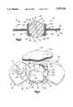
- FIG. 6is a perspective view, partially cut away, of a ball and socket joint which is constructed in accordance with a second embodiment of the present invention.
- FIG. 7is a perspective view of the ball and socket joint of FIG. 6 shown in an operating position.
- the present inventionrelates to a ball and socket joint which is part of a manually operable control assembly for controlling an electrically operated device in a vehicle, such as an outside rear view mirror.
- FIG. 1illustrates a ball and socket joint 10 which is part of a control assembly 12 for controlling an electrically operated mirror 14 of a vehicle.
- the ball and socket joint 10includes a socket 20 which is fixed in the vehicle in a manner not shown.
- a plurality of lead wires 22extend between the ball and socket joint 10 and the mirror 14.
- a manually engageable member in the form of a cap 30is attached to a ball stud 40 for movement with the ball stud.
- the lead wires 22are connected in a known manner with electrical contacts (not shown) in the ball and socket joint 10, so that movement of the ball stud 40 relative to the socket 20, in a manner described below, causes electric current to flow through the lead wires to control the positioning of the mirror 14 in a known manner.
- the ball stud 40(FIG. 5) is molded as one rigid piece from plastic or from metal.
- the ball stud 40includes a ball end 50, a shank 52, and a button 54 which are all centered on a longitudinal central axis 56 of the ball stud 40.
- the axis 56forms a central axis of the ball and socket joint 10 when the ball stud 40 is assembled with the socket 20.
- the shank 52 (FIG. 5) of the ball stud 40is fixed for movement with the ball end 50.
- the shank 52has a cylindrical configuration centered on the axis 56.
- the button 54has a disc-shaped configuration centered on the axis 56 and is fixed for movement with the shank 52.
- An upper end surface 68 of the button 54extends perpendicular to the axis 56.
- the socket 20is molded as one rigid piece from a plastic material such as DuPont Delrin® brand thermoplastic.
- the socket 20(FIG. 3) includes a socket wall 82 and an annular mounting flange 80 which extends radially outward from the socket wall.
- the mounting flange 80has planar upper and lower side surfaces 84 and 86 which extend parallel to each other and perpendicular to the axis 56.
- the mounting flange 80is connected with the vehicle in a known manner (not shown) to secure the ball and socket joint 10 in the vehicle.
- a retainer opening 100(FIG. 5) is formed in the mounting flange 80 of the socket 20.
- the retainer opening 100has a circular cross-sectional configuration.
- the retainer opening 100extends axially through the mounting flange 80, between the upper and lower side surfaces 84 and 86 of the mounting flange.
- a circumferentially extending cam member 110(FIGS. 4 and 5) is formed on the mounting flange 80 of the socket 20.
- the cam member 110has a cam surface 112 which is presented generally away from the mounting flange 80, that is, in an upward direction as viewed in FIGS. 4 and 5.
- the cam surface 112slopes toward the retainer opening 100 and terminates at the retainer opening.
- the cam member 110has a circumferential extent of 45 degrees about the axis 56.
- the socket wall 82(FIG. 3) of the socket 20 defines a chamber 120 in the socket.
- the socket wall 82has a generally cylindrical, tubular configuration.
- the socket wall 82includes a cylindrical main body 122 having a generally cylindrical inner surface 124 which is centered on the axis 56.
- An upper portion 126 of the socket wall 82projects above the mounting flange 80 as viewed in FIG. 3.
- a lower portion 128 of the socket wall 82projects below the mounting flange 80 as viewed in FIG. 3.
- the first upper lip 130has an inner peripheral surface 140 (FIG. 2) which is formed as a portion of an imaginary cylinder centered on the axis 56.
- the imaginary cylinderhas a diameter which is less than the diameter of the spherical external bearing surface 60 of the ball end 50.
- a pair of planar first guide surfaces 142 and 144form the circumferential boundaries of the first upper lip 130.
- the first guide surfaces 142 and 144lie in a plane which extends parallel to the axis 56.
- the socket wall 82includes a second upper lip 146 (FIG. 2) which is identical in configuration to the first upper lip 130.
- the second upper lipis disposed diametrically opposite the first upper lip 130 and extends radially inward from the upper portion 126 of the socket wall 82.
- the second upper lip 146has an internal bearing surface 148 (FIG. 1) which is formed as a portion of the same spherical surface as is the internal bearing surface 132 on the first upper lip 130.
- the second upper lip 146has an inner peripheral surface 150 which is formed as a portion of the same cylinder as is the inner peripheral surface 140 on the first upper lip 130.
- the second upper lip 146is bounded circumferentially by pair of planar second guide surfaces 152 and 154 (FIG. 2) which lie in a plane which extends parallel to the axis 56.
- the plane of the second guide surfaces 152 and 154is spaced apart from the plane of the first guide surfaces 142 and 144 by a distance which is equal to or slightly greater than the distance between the side surfaces 64 and 66 of the ball end 50.
- the guide surfaces 142, 144, 152 and 154define an insertion channel or keyway 160 (FIGS. 2, 4 and 5) in the socket 20 through which the ball end 50 is movable into the chamber 120.
- the provision of the insertion channel 160 in the socket 20also enables removal of an upper die core (not shown) from the chamber 120, during molding of the socket.
- the insertion channel 160is bounded on one side by the plane of the first guide surfaces 142 and 144, on the opposite side by the plane of the second guide surfaces 152 and 154, and on the ends by the portions of the cylindrical inner surface 124 of the socket wall 82 which extend between the first guide surfaces and the second guide surfaces.
- the insertion channel 160is oriented relative to the retainer opening 100 (FIG. 2) so that an imaginary plane through the center of the insertion channel, parallel to and equidistant between the guide surfaces 142, 144, 152 and 154, is angularly offset from the retainer opening by 45 degrees about the axis 56.
- the lower portion 128 of the socket wall 82is disposed below the mounting flange 80 as viewed in FIG. 3.
- the lower portion 128 of the socket wall 82is angularly offset by 90 degrees from the upper portion 126 about the axis 56.
- a first lower lip 162 (FIG. 3) of the socket 20extends radially inward from the lower portion 128 of the socket wall 82.
- the first lower lip 162has an internal bearing surface 164 which is formed as a portion of the same spherical surface as are the internal bearing surfaces 132 and 138 on the upper lips 130 and 146, respectively.
- the first lower lip 162has an inner peripheral surface 165 which is formed as a portion of the same cylinder as are the inner peripheral surfaces 140 and 150 on the upper lips 130 and 146, respectively.
- the socket wall 82includes a second lower lip 166 which is identical in configuration to and located diametrically opposite the first lower lip 162.
- the second lower lip 166extends radially inward from the lower portion 128 of the socket wall 82.
- the second lower lip 166has an internal bearing surface 168 which is formed as a portion of the same spherical surface as are the internal bearing surfaces 132, 138 and 164 on the other three lips 130, 146 and 162, respectively.
- the open space between the lower lips 162 and 166 on the socket 20enables removal of a lower die core (not shown) from the chamber 120 during molding of the socket.
- the cap 30(FIG. 1) is fixed to the ball stud 40 for movement with the ball stud. Specifically, the upper end surface 68 of the button 54 on the ball stud 40 is secured in a known manner (not shown), such as by adhesive or welding, to the underside of the cap 30. The cap 30 is manually engageable by an occupant of the vehicle on which the control assembly 12 is mounted, to effect movement of the ball stud 40 relative to the socket 20.
- a retainer 180extends from the underside of the cap 30.
- the retainer 180has a cylindrical or rod-like configuration and extends parallel to the axis 56 at a location spaced apart from the ball stud 40.
- the retainer 180is disposed a predetermined distance from the axis 56.
- the retainer 180is made from a resiliently deflectable material.
- a first end portion 182 of the retainer 180is fixed for movement with the cap 30 and, thereby, fixed for movement with the ball stud 40.
- a second end portion 184 of the retainer 180is spaced apart from the first end portion 182 and is resiliently deflectable relative to the first end portion.
- the retainer 180is shown in the drawings in a free condition and is movable or bendable from the free condition to a deflected condition (not shown).
- the retainer 180is movable from the free condition to the deflected condition upon the application of a force greater than a predetermined force to the second end portion 184 of the retainer.
- the retainer 180when in the deflected condition, has an arcuate configuration and the second end portion 184 is deflected relative to the first end portion 182.
- the ball stud 40is assembled with the socket 20 by moving the ball end 50 in a first direction as indicated by the arrow 186 into the open upper end of the socket between the upper lips 130 and 146, that is, in a downward direction as viewed in FIG. 5.
- the first direction 186extends parallel to the axis 56.
- the side surfaces 64 and 66 on the ball end 50act as a key in the keyway or insertion channel 160 of the socket 20.
- the ball stud 40is oriented relative to the socket 20 so that the side surface 66 on the ball end 50 engages the guide surfaces 142 and 144 on the socket, and the side surface 64 on the ball end engages the guide surfaces 152 and 154 on the socket. This engagement prevents the ball end 50 from rotating relative to the socket 20, about the axis 56, while the ball end is being moved axially into the socket in the first direction 186.
- the cap 30 including the retainer 180is moving, in the first direction 186, toward the mounting flange 80.
- the second end portion 184 of the retainer 180engages the cam surface 112 on the socket 20 at a position angularly offset from the retainer opening 100 by 45 degrees about the axis 56.
- the center point 62 of the ball endcoincides with the center point 134 of the socket.
- the parts of the ball and socket joint 10are in an assembly position.
- the second end portion 184 of the retainer 180becomes angularly aligned with the retainer opening 100 in the socket 20.
- the second end portion 184 of the retainer 180enters into the retainer opening 100.
- the side surfaces 64 and 66 on the ball end 50disengage from the guide surfaces 142, 144, 152 and 154 on the socket 20.
- the ball end 50is no longer prevented from rotating within the chamber 120 about the axis 56.
- the potential energy which is stored in the resiliently deflected retainer 180is released and results in relative rotation about the axis 56 between the retainer and the ball end 50.
- the engagement of the retainer 180 in the retainer opening 100prevents the retainer from rotating by more than a few degrees relative to the socket 20 about the axis 56. Therefore, the ball end 50 rotates relative to the retainer.
- the ball end 50, and the shank 52rotate relative to the socket 20 about the axis 56, in a counterclockwise direction as viewed in FIG. 2.
- the ball end 50, and the ball stud 40 as a wholerotate 45 degrees about the axis 56 from the assembly position to an operating position as shown in FIGS. 2 and 4.
- the retainer 180stays in the retainer opening 100 and returns to its free (straightened) condition as a result of the rotation of the ball end 50.
- the spherical external bearing surface 60 on the ball endis in sliding engagement with the spherical internal bearing surfaces 132 and 148 (FIG. 1) on the first and second upper lips 130 and 146, respectively, on the socket 20.
- the spherical external bearing surface 60 on the ball end 50is also in sliding engagement with the spherical internal bearing surfaces 164 and 168 on the first and second lower lips 162 and 166, respectively, on the socket 20.
- the engagement between the external bearing surface 60 on the ball end 50 and the internal bearing surfaces 132, 148, 164 and 168 (FIG. 3) on the socket 20supports the ball end 50 for rotation in the chamber 120 in the socket. The ball stud 40 is thus supported for pivotal movement relative to the socket 20.
- the ball end 50When the ball end 50 is in the operating position, the ball end 50 is rotatable relative to the socket 20, in the chamber 120, about a second axis 190 (FIG. 2) extending through the center point 134 of the socket 20.
- the second axis 190extends perpendicular to the first axis 56.
- the ball end 50When the ball end 50 is in the operating position, the ball end 50 also is rotatable relative to the socket 20, in the chamber 120, about a third axis 192 extending through the center point 134 of the socket 20.
- the third axis 192extends perpendicular to the first axis 56 and to the second axis 190.
- the engagement of the retainer 180 in the retainer opening 100prevents the ball end 50 from rotating about the axis 56 relative to the socket from the operating position back to the assembly position. Specifically, unless a rotational force (about the axis 56) in an amount greater than the predetermined amount is applied to the ball stud 40, the retainer 180 does not deflect sufficiently from its free condition to enable rotation of the ball end 50 from the operation position back to the assembly position.
- the predetermined amount of forceis greater than any amount reasonably expected to be applied to the ball stud 40 in the operation of the ball and socket joint 10 when mounted in the vehicle.
- the ball end 50is maintained axially in the socket 20.
- the inner peripheral surfaces on the lips 130, 146, 162 and 166 on the socket 20are formed as portions of a cylinder having a diameter less than the diameter of the ball end 50.
- the lower lips 162 and 166 on the socket 20prevent the ball end 50 from being moved axially out of the socket, in a second direction 188 opposite to the first direction 186.
- the upper lips 130 and 146 on the socket 20prevent the ball end 50 from being moved axially out of the socket in the first direction 186.
- FIGS. 6 and 7illustrate a ball and socket joint 200 which is constructed in accordance with a second embodiment of the present invention.
- the ball and socket joint 200is similar to the ball and socket joint 10 (FIGS. 1-5) and can be substituted for the ball and socket joint 10 in the control assembly 12.
- Parts of the ball and socket joint 200 which are the same as or similar to corresponding parts of the ball and socket joint 10are given the same reference numerals with the suffix "a" added for clarity.
- the ball and socket joint 200includes a rigid socket 20a which has an insertion channel 160a.
- the socket 20aalso has a retainer opening in the form of a radially and axially extending slot 100a in the socket wall 82a.
- the slot 100ais offset angularly, about the axis 56a, by a predetermined number of degrees from the central plane of the insertion channel 160a. In the illustrated embodiment, the slot 100a is offset angularly by about 45 degrees from the central plane of the insertion channel 160a, in a clockwise direction as viewed from above in FIGS. 6 and 7.
- a cam surface 112ais formed on the socket wall 82a.
- the cam surface 112aextends from the top (as viewed in FIG. 6) of the socket wall 82a down to the slot 100a.
- the cam surface 112ahas a circumferential extent of about 45 degrees about the axis 56a.
- the ball stud 40aincludes a retainer in the form of a resilient post 180a.
- the ball stud 40is, otherwise, sufficiently rigid that it does not deform during assembly or operation of the ball and socket joint 200.
- the post 180ahas a first end portion 182a fixed for movement with the ball end 50a and a second end portion 184a which is resiliently deflectable relative to the first end portion.
- the post 180aextends radially outward from the one side surface 64a of the ball end 50a, in a direction perpendicular to the axis 56a.
- the post 180ais resiliently deflectable between a free condition as viewed in FIG. 7 and a deflected condition as viewed in FIG. 6.
- the post 180ahas an arcuate configuration when in the deflected condition.
- the ball stud 40ais assembled with the socket 20a by moving the ball end 50a in the first direction 186a (downward as viewed in FIGS. 6 and 7) into the insertion channel 160a in the socket.
- the ball end 50ais moved into the socket 20a in an orientation so that the planar side surfaces on the ball end engage with the guide surfaces on the socket. This engagement prevents the ball end 50a from rotating relative to the socket 20a, about the axis 56a, while the ball end is being moved axially into the socket.
- the post 180aWhen the ball end 50a enters into the insertion channel 160a in the socket 20a, the post 180a is angularly offset from the slot 100a by 45 degrees about the axis 56a.
- the second end portion 184a of the post 180aengages the cam surface 112a on the socket 20a.
- the cam surface 112a on the socketdeflects the post 180a, from its free condition toward a deflected position in which the second end portion 184a of the post is angularly aligned with the slot 100a in the socket wall 82a.
- the post 180adeflects relative to the ball end 50a.
- the resilience of the post 180aattempts to produce relative rotation about the axis 56a between the post 180a and the ball end 50a.
- the engagement of the ball end 50a in the insertion channel 160atemporarily prevents such relative rotation.
- the planar side surfaces on the ball end 50adisengage from the planar guide surfaces which form the insertion channel 160a in the socket.
- the second end portion 184a of the post 180abecomes angularly aligned with the slot 100a in the socket 20a.
- the second end portion 184 of the post 180aenters into the slot 100a.
- the engagement of the post 180a in the slot 100aprevents the post from rotating by more than a few degrees relative to the socket 20a about the axis 56a.
- the parts of the ball and socket joint 200are in an assembly position.
- the potential energy which is stored in the resiliently deflected post 180ais released and results in rotation of the ball end 50a relative to the post 180a, in a counterclockwise direction as viewed in FIGS. 6 and 7.
- the ball end 50a, and the ball stud 40a as a whole,rotate about the axis 56a from the assembly position shown in FIG. 6 to the operating position shown in FIG. 7.
- the post 180astays in the slot 100a and returns to its free condition.
- the ball stud 40aWhen the ball end 50a of the ball stud 40a is in the operating position, the ball stud is pivotable relative to the socket 20a, about a second axis (not shown) which extends through the center of the ball end 50a and through the center of the mounting flange 80a.
- the ball stud 40ais also pivotable about a third axis (not shown) which extends through the center of the ball end 50a and perpendicular to the side surface 64a--that is, longitudinally through the post 180.
- the second axis 190 and the third axisextend perpendicular to each other and to the first axis 56a.
- the engagement of the post 180a in the slot 100aprevents the ball end 50a from rotating in a significant amount about the axis 56a relative to the socket 20a.
- the ball end 50acan not be returned from the operating position back to the assembly position.
- the ball end 50ais maintained axially in the socket 20a in the same manner as the ball end 50 is maintained in the socket 20.
Landscapes
- Engineering & Computer Science (AREA)
- General Engineering & Computer Science (AREA)
- Mechanical Engineering (AREA)
- Physics & Mathematics (AREA)
- Geometry (AREA)
- Pivots And Pivotal Connections (AREA)
Abstract
Description
Claims (14)
Priority Applications (1)
| Application Number | Priority Date | Filing Date | Title |
|---|---|---|---|
| US08/651,265US5755526A (en) | 1996-05-23 | 1996-05-23 | Ball and socket joint |
Applications Claiming Priority (1)
| Application Number | Priority Date | Filing Date | Title |
|---|---|---|---|
| US08/651,265US5755526A (en) | 1996-05-23 | 1996-05-23 | Ball and socket joint |
Publications (1)
| Publication Number | Publication Date |
|---|---|
| US5755526Atrue US5755526A (en) | 1998-05-26 |
Family
ID=24612188
Family Applications (1)
| Application Number | Title | Priority Date | Filing Date |
|---|---|---|---|
| US08/651,265Expired - LifetimeUS5755526A (en) | 1996-05-23 | 1996-05-23 | Ball and socket joint |
Country Status (1)
| Country | Link |
|---|---|
| US (1) | US5755526A (en) |
Cited By (27)
| Publication number | Priority date | Publication date | Assignee | Title |
|---|---|---|---|---|
| US6409413B1 (en)* | 1999-06-18 | 2002-06-25 | Sandia Corporation | Large displacement spherical joint |
| US20020197107A1 (en)* | 2001-03-30 | 2002-12-26 | Robert Granata | Articulating fastener assembly |
| US20030086756A1 (en)* | 2001-11-07 | 2003-05-08 | Trotter Jason K | Modular linkage system |
| EP1344952A1 (en)* | 2002-03-05 | 2003-09-17 | Deere & Company | Ball joint |
| US20040198163A1 (en)* | 2002-11-12 | 2004-10-07 | Wai Fuk Chai Alvin | Frictional joint for toys |
| US20040258471A1 (en)* | 2001-03-30 | 2004-12-23 | Robert Granata | Articulating fastener assembly |
| US6875388B2 (en) | 2001-11-07 | 2005-04-05 | Illinois Tool Works Inc. | Method for making a ball and socket joint |
| US20050141116A1 (en)* | 2001-12-07 | 2005-06-30 | Johannes Andreas Petrus Schalkwijk | Mirror adjustment mechanism with electrical connection |
| US6929271B2 (en) | 2001-11-09 | 2005-08-16 | Illinois Tool Works Inc. | Hydraulically compensated stabilizer system |
| US7077717B2 (en) | 2003-05-27 | 2006-07-18 | Mattel, Inc. | Doll with angled and jointed torso |
| US20080112753A1 (en)* | 2006-11-09 | 2008-05-15 | The Boeing Company | Socket joint for tie-rod attachment system and method |
| US20090120428A1 (en)* | 2007-11-09 | 2009-05-14 | Mario Rabinowitz | Latching solar concentrator pivoted mirrors during off-power period |
| US20090206826A1 (en)* | 2008-02-19 | 2009-08-20 | Thomas Lawson Booth | Strut position sensor |
| US20100052343A1 (en)* | 2007-01-26 | 2010-03-04 | Richard Lester Hallett | Fitting, crane hook, and crane hook assembly |
| USD628143S1 (en)* | 2009-10-02 | 2010-11-30 | Tomtom International B.V. | Non-integrated mounting device for use in a vehicle |
| US7856748B1 (en)* | 2007-09-10 | 2010-12-28 | Mertz Dean W | Bipod support and mount |
| US20110028286A1 (en)* | 2009-07-31 | 2011-02-03 | Andre Nortje | "All Ball" complete strength, cardiovascular, body building exercise machine |
| CN102834218A (en)* | 2010-10-22 | 2012-12-19 | 宝马股份公司 | Component connection system and method for connecting varous components of the component connection system in non-detachable manner |
| US20130036594A1 (en)* | 2010-04-28 | 2013-02-14 | Bayerische Motoren Werke Aktiengesellschaft | Component Connection and/or Method for Connecting Components |
| US8413398B1 (en)* | 2008-06-20 | 2013-04-09 | 3Form, Inc. | Ball pivot assemblies and systems and methods incorporating the same |
| US20150144755A1 (en)* | 2013-11-22 | 2015-05-28 | Chiun Mai Communication Systems, Inc. | Holder for portable electronic |
| US20150251511A1 (en)* | 2014-03-04 | 2015-09-10 | Federal-Mogul Motorparts Corporation | Ball joint assembly for a control arm |
| US20180029195A1 (en)* | 2016-07-28 | 2018-02-01 | Jason Green | Ball joint and apparatus for holding an object |
| US20200232600A1 (en)* | 2019-01-17 | 2020-07-23 | Dwight Dixon | Pole Coupling Assembly |
| US10756773B2 (en) | 2015-01-05 | 2020-08-25 | Iomounts, Llc | Apparatus and method for supporting an article |
| DE102021108506B3 (en) | 2021-04-06 | 2022-04-28 | Mekra Lang Gmbh & Co. Kg | Indirect rear view system with index geometry comprising an adjustment ball with over-rotation indexing |
| EP4534863A1 (en)* | 2023-10-05 | 2025-04-09 | Valeo Systèmes d'Essuyage | Ball-joint assembly for a windscreen wiper module |
Citations (8)
| Publication number | Priority date | Publication date | Assignee | Title |
|---|---|---|---|---|
| US1664893A (en)* | 1926-02-20 | 1928-04-03 | Meyering Bernard | Joint |
| CA569470A (en)* | 1959-01-27 | E. Saloranta Arvo | Coupling mount for mortars | |
| US3146008A (en)* | 1962-07-11 | 1964-08-25 | M T Liquidation Corp | Self-aligning ball joint connection |
| US3795922A (en)* | 1972-01-14 | 1974-03-12 | J Herbert | Complete knee prothesis |
| US3803685A (en)* | 1972-03-29 | 1974-04-16 | Tuthill Pump Co | Ball joint and method of fabrication |
| US4338038A (en)* | 1979-01-17 | 1982-07-06 | Regie Nationale Des Usines Renault | Ball-and-socket joint for multiarticulate arm |
| US5360282A (en)* | 1993-11-01 | 1994-11-01 | General Motors Corporation | Vehicle headlamp adjuster ball and socket assembly |
| US5486174A (en)* | 1993-02-24 | 1996-01-23 | Soprane S.A. | Fastener for the osteosynthesis of the spinal column |
- 1996
- 1996-05-23USUS08/651,265patent/US5755526A/ennot_activeExpired - Lifetime
Patent Citations (8)
| Publication number | Priority date | Publication date | Assignee | Title |
|---|---|---|---|---|
| CA569470A (en)* | 1959-01-27 | E. Saloranta Arvo | Coupling mount for mortars | |
| US1664893A (en)* | 1926-02-20 | 1928-04-03 | Meyering Bernard | Joint |
| US3146008A (en)* | 1962-07-11 | 1964-08-25 | M T Liquidation Corp | Self-aligning ball joint connection |
| US3795922A (en)* | 1972-01-14 | 1974-03-12 | J Herbert | Complete knee prothesis |
| US3803685A (en)* | 1972-03-29 | 1974-04-16 | Tuthill Pump Co | Ball joint and method of fabrication |
| US4338038A (en)* | 1979-01-17 | 1982-07-06 | Regie Nationale Des Usines Renault | Ball-and-socket joint for multiarticulate arm |
| US5486174A (en)* | 1993-02-24 | 1996-01-23 | Soprane S.A. | Fastener for the osteosynthesis of the spinal column |
| US5360282A (en)* | 1993-11-01 | 1994-11-01 | General Motors Corporation | Vehicle headlamp adjuster ball and socket assembly |
Cited By (52)
| Publication number | Priority date | Publication date | Assignee | Title |
|---|---|---|---|---|
| US6409413B1 (en)* | 1999-06-18 | 2002-06-25 | Sandia Corporation | Large displacement spherical joint |
| US6857809B2 (en)* | 2001-03-30 | 2005-02-22 | Robert Granata | Articulating fastener assembly |
| US20020197107A1 (en)* | 2001-03-30 | 2002-12-26 | Robert Granata | Articulating fastener assembly |
| US7435031B2 (en) | 2001-03-30 | 2008-10-14 | Robert Granata | Articulating fastener assembly |
| US7922135B2 (en) | 2001-03-30 | 2011-04-12 | Robert Granata | Articulating fastener assembly |
| US20040258471A1 (en)* | 2001-03-30 | 2004-12-23 | Robert Granata | Articulating fastener assembly |
| US20050123345A1 (en)* | 2001-11-07 | 2005-06-09 | Trotter Jason K. | Method and apparatus for making a ball and socket joint and joint made by same |
| US6875388B2 (en) | 2001-11-07 | 2005-04-05 | Illinois Tool Works Inc. | Method for making a ball and socket joint |
| US20030086756A1 (en)* | 2001-11-07 | 2003-05-08 | Trotter Jason K | Modular linkage system |
| US6929271B2 (en) | 2001-11-09 | 2005-08-16 | Illinois Tool Works Inc. | Hydraulically compensated stabilizer system |
| US20050141116A1 (en)* | 2001-12-07 | 2005-06-30 | Johannes Andreas Petrus Schalkwijk | Mirror adjustment mechanism with electrical connection |
| US7473001B2 (en)* | 2001-12-07 | 2009-01-06 | Mci (Mirror Controls International) Netherlands B.V. | Mirror adjustment mechanism with electrical connection |
| EP1344952A1 (en)* | 2002-03-05 | 2003-09-17 | Deere & Company | Ball joint |
| US7566256B2 (en) | 2002-11-12 | 2009-07-28 | Mattel, Inc. | Frictional joint for toys |
| US7021989B2 (en) | 2002-11-12 | 2006-04-04 | Mattel, Inc. | Frictional joint for toys |
| US20040198163A1 (en)* | 2002-11-12 | 2004-10-07 | Wai Fuk Chai Alvin | Frictional joint for toys |
| US20060228985A1 (en)* | 2002-11-12 | 2006-10-12 | Wai Fuk C A | Frictional joint for toys |
| US7077717B2 (en) | 2003-05-27 | 2006-07-18 | Mattel, Inc. | Doll with angled and jointed torso |
| US7497638B2 (en)* | 2006-11-09 | 2009-03-03 | The Boeing Company | Socket joint for tie-rod attachment system and method |
| US20080112753A1 (en)* | 2006-11-09 | 2008-05-15 | The Boeing Company | Socket joint for tie-rod attachment system and method |
| US8662549B2 (en) | 2007-01-26 | 2014-03-04 | Airbus Operations Limited | Fitting, crane hook, and crane hook assembly |
| US20100052343A1 (en)* | 2007-01-26 | 2010-03-04 | Richard Lester Hallett | Fitting, crane hook, and crane hook assembly |
| US8313131B2 (en)* | 2007-01-26 | 2012-11-20 | Airbus Operations Limited | Fitting, crane hook, and crane hook assembly |
| US7856748B1 (en)* | 2007-09-10 | 2010-12-28 | Mertz Dean W | Bipod support and mount |
| US20090120428A1 (en)* | 2007-11-09 | 2009-05-14 | Mario Rabinowitz | Latching solar concentrator pivoted mirrors during off-power period |
| US7878667B2 (en)* | 2007-11-09 | 2011-02-01 | Mario Rabinowitz | Latching solar concentrator pivoted mirrors during off-power period |
| US8008910B2 (en) | 2008-02-19 | 2011-08-30 | Strattec Power Access Llc | Strut position sensor including a magnet mounted on an idler gear contained in a stator portion, which is movable relative to a rotor portion connected to the strut, and a galvanomagnetic sensor in the stator portion for detecting angular position of the strut |
| US20090206826A1 (en)* | 2008-02-19 | 2009-08-20 | Thomas Lawson Booth | Strut position sensor |
| US8413398B1 (en)* | 2008-06-20 | 2013-04-09 | 3Form, Inc. | Ball pivot assemblies and systems and methods incorporating the same |
| US8079941B2 (en)* | 2009-07-31 | 2011-12-20 | Andre Nortje | Exercising apparatus |
| US20110028286A1 (en)* | 2009-07-31 | 2011-02-03 | Andre Nortje | "All Ball" complete strength, cardiovascular, body building exercise machine |
| USD628143S1 (en)* | 2009-10-02 | 2010-11-30 | Tomtom International B.V. | Non-integrated mounting device for use in a vehicle |
| US20130036594A1 (en)* | 2010-04-28 | 2013-02-14 | Bayerische Motoren Werke Aktiengesellschaft | Component Connection and/or Method for Connecting Components |
| US9050690B2 (en)* | 2010-04-28 | 2015-06-09 | Bayerische Motoren Werke Aktiengesellschaft | Component connection and/or method for connecting components |
| US9222500B2 (en)* | 2010-10-22 | 2015-12-29 | Bayerische Motoren Werke Aktiengesellschaft | Component connection and method for the detachable connection of the components of a component connection |
| US20130071181A1 (en)* | 2010-10-22 | 2013-03-21 | Bayerische Motoren Werke Aktiengesellschaft | Component Connection and Method for the Detachable Connection of the Components of a Component Connection |
| CN102834218A (en)* | 2010-10-22 | 2012-12-19 | 宝马股份公司 | Component connection system and method for connecting varous components of the component connection system in non-detachable manner |
| CN102834218B (en)* | 2010-10-22 | 2015-04-01 | 宝马股份公司 | Component connection system and method for connecting varous components of the component connection system in non-detachable manner |
| US20150144755A1 (en)* | 2013-11-22 | 2015-05-28 | Chiun Mai Communication Systems, Inc. | Holder for portable electronic |
| US9366383B2 (en)* | 2013-11-22 | 2016-06-14 | Chiun Mai Communication Systems, Inc. | Holder for portable electronic |
| US20150251511A1 (en)* | 2014-03-04 | 2015-09-10 | Federal-Mogul Motorparts Corporation | Ball joint assembly for a control arm |
| US9327570B2 (en)* | 2014-03-04 | 2016-05-03 | Federal-Mogul Motorparts Corporation | Ball joint assembly for a control arm |
| US11405066B2 (en) | 2015-01-05 | 2022-08-02 | Kustom Cycles, Inc. | Apparatus and method for supporting an article |
| US10756773B2 (en) | 2015-01-05 | 2020-08-25 | Iomounts, Llc | Apparatus and method for supporting an article |
| US12081255B2 (en) | 2015-01-05 | 2024-09-03 | Kustom Cycles, Inc. | Apparatus and method for supporting an article |
| US20180029195A1 (en)* | 2016-07-28 | 2018-02-01 | Jason Green | Ball joint and apparatus for holding an object |
| US20200232600A1 (en)* | 2019-01-17 | 2020-07-23 | Dwight Dixon | Pole Coupling Assembly |
| EP4134279A1 (en) | 2021-04-06 | 2023-02-15 | MEKRA LANG GmbH & Co. KG | Indirect rear view system with indexing geometry comprising an adjustment ball with excess rotation indexing |
| DE102021108506B3 (en) | 2021-04-06 | 2022-04-28 | Mekra Lang Gmbh & Co. Kg | Indirect rear view system with index geometry comprising an adjustment ball with over-rotation indexing |
| US12416781B2 (en) | 2021-04-06 | 2025-09-16 | Mekra Lang Gmbh & Co. Kg | Indirect rear viewing system with index geometry comprising an adjustment ball with overtwist indexing |
| EP4534863A1 (en)* | 2023-10-05 | 2025-04-09 | Valeo Systèmes d'Essuyage | Ball-joint assembly for a windscreen wiper module |
| WO2025073539A1 (en)* | 2023-10-05 | 2025-04-10 | Valeo Systèmes d'Essuyage | Ball-joint assembly for a windscreen wiper module |
Similar Documents
| Publication | Publication Date | Title |
|---|---|---|
| US5755526A (en) | Ball and socket joint | |
| US4915493A (en) | Automotive rear view mirror assembly | |
| US5046951A (en) | Wiring apparatus for making an electrical connection between a steering wheel and a steering column of a motor vehicle | |
| US20030230475A1 (en) | One-way rotary switch | |
| EP1843364B1 (en) | Rotation driving device | |
| US6674183B1 (en) | Rotary switch with rotatable contact | |
| US3902152A (en) | Electrical control having an insulated shaft extension | |
| US5665948A (en) | Automobile knob switch | |
| US5773774A (en) | Electrical switch with omega shaped return spring | |
| US20030167858A1 (en) | Rotary sensor of simple construction for detecting angle of rotation transmitted from outside | |
| US6310535B2 (en) | Rotary electric part superior in click feeling | |
| JP3610147B2 (en) | Rod antenna mounting device for vehicle | |
| JP2024139176A (en) | Connecting Devices | |
| JP2003525812A (en) | Irreversible wiper park switch for wiper drive | |
| US7474353B2 (en) | Digital camera and switch device | |
| US2594493A (en) | Circuit controlling device | |
| US5406041A (en) | Rotary vacuum valve and electric switch assembly | |
| JP3723714B2 (en) | Rotating electrical parts | |
| JP2615476B2 (en) | Lever switch for vehicle | |
| US5861593A (en) | Modular switch stalk assemblable in different orientations to provide different rotation features | |
| JP2596432Y2 (en) | Automotive knob switch | |
| JP2001098800A (en) | Mounting structure of cylinder lock in key cylinder device | |
| KR200187108Y1 (en) | Intermittent movement apparatus of rotary switch | |
| JPS58157365A (en) | Stepping motor with member responding in linear line | |
| JPH0419248A (en) | Operating component fixing structure |
Legal Events
| Date | Code | Title | Description |
|---|---|---|---|
| AS | Assignment | Owner name:TRW INC., OHIO Free format text:ASSIGNMENT OF ASSIGNORS INTEREST;ASSIGNOR:STANEVICH, KENNETH W.;REEL/FRAME:008019/0297 Effective date:19960520 | |
| FEPP | Fee payment procedure | Free format text:PAYOR NUMBER ASSIGNED (ORIGINAL EVENT CODE: ASPN); ENTITY STATUS OF PATENT OWNER: LARGE ENTITY | |
| STCF | Information on status: patent grant | Free format text:PATENTED CASE | |
| FPAY | Fee payment | Year of fee payment:4 | |
| AS | Assignment | Owner name:JPMORGAN CHASE BANK, NEW YORK Free format text:THE US GUARANTEE AND COLLATERAL AGREEMENT;ASSIGNOR:TRW AUTOMOTIVE U.S. LLC;REEL/FRAME:014022/0720 Effective date:20030228 | |
| FPAY | Fee payment | Year of fee payment:8 | |
| FPAY | Fee payment | Year of fee payment:12 | |
| AS | Assignment | Owner name:JPMORGAN CHASE BANK, N.A., AS COLLATERAL AGENT, NE Free format text:SECURITY AGREEMENT;ASSIGNORS:TRW VEHICLE SAFETY SYSTEMS INC.;TRW AUTOMOTIVE U.S. LLC;KELSEY-HAYES COMPANY;REEL/FRAME:029529/0534 Effective date:20120928 | |
| AS | Assignment | Owner name:TRW VEHICLE SAFETY SYSTEMS INC., MICHIGAN Free format text:RELEASE OF SECURITY INTEREST;ASSIGNOR:JPMORGAN CHASE BANK, N.A.;REEL/FRAME:031645/0697 Effective date:20131028 Owner name:TRW INTELLECTUAL PROPERTY CORP., MICHIGAN Free format text:RELEASE OF SECURITY INTEREST;ASSIGNOR:JPMORGAN CHASE BANK, N.A.;REEL/FRAME:031645/0697 Effective date:20131028 Owner name:TRW AUTOMOTIVE U.S. LLC, MICHIGAN Free format text:RELEASE OF SECURITY INTEREST;ASSIGNOR:JPMORGAN CHASE BANK, N.A.;REEL/FRAME:031645/0697 Effective date:20131028 Owner name:KELSEY-HAYES COMPANY, MICHIGAN Free format text:RELEASE OF SECURITY INTEREST;ASSIGNOR:JPMORGAN CHASE BANK, N.A.;REEL/FRAME:031645/0697 Effective date:20131028 |