US5754890A - System for automatic identification of a computer data entry device interface type using a transistor to sense the voltage generated by the interface and output a matching voltage level - Google Patents
System for automatic identification of a computer data entry device interface type using a transistor to sense the voltage generated by the interface and output a matching voltage levelDownload PDFInfo
- Publication number
- US5754890A US5754890AUS08/595,345US59534596AUS5754890AUS 5754890 AUS5754890 AUS 5754890AUS 59534596 AUS59534596 AUS 59534596AUS 5754890 AUS5754890 AUS 5754890A
- Authority
- US
- United States
- Prior art keywords
- data
- interface
- processor
- line
- transistor
- Prior art date
- Legal status (The legal status is an assumption and is not a legal conclusion. Google has not performed a legal analysis and makes no representation as to the accuracy of the status listed.)
- Expired - Lifetime
Links
Images


Classifications
- G—PHYSICS
- G06—COMPUTING OR CALCULATING; COUNTING
- G06F—ELECTRIC DIGITAL DATA PROCESSING
- G06F3/00—Input arrangements for transferring data to be processed into a form capable of being handled by the computer; Output arrangements for transferring data from processing unit to output unit, e.g. interface arrangements
- G06F3/01—Input arrangements or combined input and output arrangements for interaction between user and computer
- G06F3/03—Arrangements for converting the position or the displacement of a member into a coded form
- G06F3/033—Pointing devices displaced or positioned by the user, e.g. mice, trackballs, pens or joysticks; Accessories therefor
- G06F3/038—Control and interface arrangements therefor, e.g. drivers or device-embedded control circuitry
- G06F3/0383—Signal control means within the pointing device
Definitions
- the present inventionrelates generally to computer pointing devices, and, more specifically, to a system and method for automatic identification of a computer pointing device interface.
- Computersare used in many applications. To position a cursor on a computer display and/or to enter commands, a computer pointing device is typically used. Pointing devices have been developed for two different interface types within the host computer. Until recently, both interface types required a specialized computer pointing device. For example, a pointing device such as a mouse was introduced in a version operable with a RS-232 interface on the computer, and also in a separate version operable with a PS/2 or mouse port interface on the computer. Subsequently, combination pointing devices, capable of operation with more than one type of interface, were introduced. However, the combination pointing devices must have the capability of identifying the type of interface to which they are connected. Therefore, it can be appreciated that there is a significant need for a combination computer pointing device that automatically identifies the interface type.
- the present inventionprovides this and other advantages as will be illustrated by the following description and accompanying figures.
- the present inventionis embodied in a system and method for the automatic identification of an interface type to which a computer input device is connected.
- the computer input devicesuch as a pointing device, generates position data corresponding to user input to the pointing device.
- the systemincludes a single sense line coupled between the interface and the pointing device where the sense line has a first voltage level generated by the interface if the interface is of a first type, and has a second voltage level different from the first voltage level generated by the interface if the interface is of a second type.
- a sensing circuit within the pointing devicedetects the voltage from the sense line and is in a first output state if the sense line has the first voltage level and a second output state if the sense line has the second voltage level.
- a processor within the pointing deviceis coupled to the sensing circuit and processes the position data in a first manner if the sensing circuit is in the first logic state and processes the position data in a second manner if the sensing circuit is in the second state.
- the pointing devicemay be a mouse, trackball, or the like.
- the systemis operable with either a PS/2 or mouse port interface or a RS-232 interface. If the pointing device is coupled to a PS/2 interface, the voltage on the sense line is greater than or equal to 0 volts. If the pointing device is coupled to a serial interface, the voltage on the sense line is less than 0 volts.
- a formatterformats the position data for transmission to the PS/2 interface, or for serial transmission to the serial interface, depending on the detected interface type.
- FIG. 1is a functional block diagram illustrating the connection of a conventional PS/2 pointing device to a PS/2 interface.
- FIG. 2is a functional block diagram illustrating the connection of a conventional serial pointing device to a serial interface.
- FIG. 3Ais a functional block diagram illustrating the connection of a conventional combination pointing device to a parallel interface.
- FIG. 3Bis a functional block diagram illustrating the connection of the conventional combination pointing device to a serial interface using a conventional adapter.
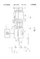
- FIG. 4is a circuit according to the present invention illustrating the sensing circuit operation to determine interface types.
- FIG. 5is a functional block diagram of a combination pointing device incorporating the sensing circuit of FIG. 4.
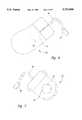
- FIG. 6illustrates a mouse incorporating the sensing circuit of FIG. 4.
- FIG. 7illustrates a trackball incorporating the sensing circuit of FIG. 4.
- FIG. 8is an electrical circuit showing the use of the I/O pin in the sensing circuit of FIG. 4 when used for multitasking operations.
- a PS/2TM pointing device 10is coupled to a PS/2 interface 12 using a cable 14 and an industry standard six pin mini-DIN plug 16.
- PS/2is a trademark of International Business Machines.
- the six pin mini-DIN plug 16connects with a corresponding six pin mini-DIN connector 16a on the computer 2.
- the cable 14 for the parallel pointing device 10includes a +5 volts DC (VDC) line 18 as well as a ground (GND) line 20.
- VDC+5 volts DC
- GNDground
- the +5 VDC and ground lines 18 and 20,supply power to the PS/2 pointing device 10.
- the PS/2 pointing device 10generates position data as a result of user input to the pointing device.
- the PS/2 pointing device 10is a mouse
- the mousegenerates position data in response to user movement of the mouse.
- the position data generated by the PS/2 pointing device 10 as well as data related to the position of one or more buttons (not shown)is transmitted to the PS/2 interface 12 using a clock line 22 and a data line 24.
- the operation of the PS/2 pointing device 10is well-known to those skilled in the art and need not be described in greater detailed herein.
- serial pointing devicesinclude a serial pointing device 30, illustrated in FIG. 2.
- the serial pointing device 30is coupled to a serial interface 32, such as an RS-232 interface, within the computer 2 using a cable 34 and an industry standard D-Sub 9 plug 36.
- the D-Sub 9 plug 36connects with a corresponding DB-9 connector 36a on the computer 2.
- the cable 34includes a "Request to Send" (RTS) line 38.
- RTS line 38is a control line used in a conventional serial port.
- the typical serial pointing device 30does not use such a control line. Instead, the RTS line 38 is used to supply a positive voltage to the serial pointing device 30.
- the positive voltage supplied to the serial pointing devicetypically ranges from +5 VDC to +12 VDC.
- the cable 34also includes a ground (GND) line 42, which is used by the serial interface 32 in supplying power to the serial pointing device 30 along with the supply voltages.
- the cable 34also includes a TxD) data line 46 and a RxD data line 48.
- the TxD data line 46typically carries data from the serial interface 32 to a peripheral.
- the conventional serial pointing device 30is a send only device, and does not receive data on the TxD data line 46. Rather, the TxD data line 46 is used to carry a negative voltage required by the serial interface 32.
- the negative voltagetypically ranges from -5 VDC to -12 VDC.
- the serial pointing device 30transmits data to the serial interface 32 using the RxD data line 48.
- Data transmitted from the serial pointing device 30includes positional data as well as data related to the position of one or more buttons (not shown) on the serial pointing device.
- the operation of the serial pointing device 30is well known in the art and need not be described in any greater detail herein.
- a conventional combination pointing device 50is illustrated in FIGS. 3A and 3B.
- the combination pointing device 50has circuitry (not shown) that allows it to function as either the PS/2 pointing device 10 (see FIG. 1) or the serial pointing device 30 (see FIG. 2).
- the usercan connect the combination pointing device 50 directly to the PS/2 interface 12 using a conventional six pin mini-DIN plug 56, as illustrated in FIG. 3A.
- the six pin mini-DIN plug 56connects with a corresponding six pin mini-DIN connector 56a on the computer 2.
- the combination pointing device 50includes a six conductor cable 60 that contains wires for use with either the PS/2 interface 12 or the serial interface 32.
- a V cc /RTS line 62provides power to the combination pointing device 50 from the PS/2 interface 12. As will be discussed below, the V cc /RTS line 62 is used by the combination pointing device 50 when coupled to either the PS/2 interface 12 or the serial interface 32 (see FIG. 3B).
- a ground (GND) line 64also is used in supplying power from the PS/2 interface 12 to the combination pointing device 50.
- a clock (CLK) line 66carries a clock signal generated by the combination pointing device 50 to synchronize the transfer of data to the PS/2 interface 12.
- a data line 68is used in conjunction with the CLK line 66 to transfer data from the combination pointing device 50 to the PS/2 interface 12.
- the data carried by the data line 68includes both positional data and data related to the position of one or more buttons (not shown) on the combination pointing device 50.
- the cable 60includes a TxD line 70 and an RxD line 72 While the TxD line 70 and the RxD line 72 are included in the cable 60, they are not used when the combination pointing device 50 is coupled to the PS/2 interface 12. However, as will be discussed below, the TxD line 70 and RxD line 72 are used when the combination pointing device 50 is coupled to the serial interface 32.
- an adapter 58is used to couple the combination pointing device 50 to the serial interface 32 as shown in FIG. 3B.
- the adapter 58includes a six pin mini-DIN connector 56a and a D-Sub 9 plug 76.
- the six pin mini-DIN plug 56 on the combination pointing device 50connects to the six pin mini-DIN connector 56a of the adapter 58, while the DB-9 plug 76 of the adapter connects to a corresponding DB-9 connector 76a on the computer 2.
- the TxD line 70 and RxD line 72are used by the combination pointing device 50 when connected to the serial interface 32 using the adapter 58.
- the adapter 58connects the V cc /RTS line 62 and the GND line 64 to the serial interface 32.
- a serial version of the combination pointing deviceis provided by the manufacturer with the DB-9 plug 76 for direct connection to the serial interface 32.
- an adapter(not shown) is provided to convert the DB-9 plug 76 on the serial version of the combination pointing device 50 to the six pin mini-DIN plug 56 for operation with the PS/2 interface 12.
- the DB-9 plug 76 to six pin mini-DIN plug 56 adapter(not shown) connects the same wires to the parallel interface, as previously discussed with respect to FIG. 3A.
- the serial version of the combination pointing device 50 with the DB-9 plug 76which is not illustrated herein, connects the lines of the cable 60 in the manner discussed above with respect to FIG. 3B directly to the serial interface 32 without the need for the adapter 58.
- the combination pointing device 50, and the data signals connected thereto,are used in the manner previously discussed.
- the drawback of the prior art system illustrated in FIGS. 3A and 3Bis that the CLK line 66 and the data line 68 must be shorted together within the adapter 58. Because the CLK line 66 and the data line 68 are shorted together, these lines are not available for other purposes. As discussed above, some of the lines within the cable 60 are used to carry power to the combination pointing device 50. For example, the TxD line 70 carries negative power from the serial interface 32 to the combination pointing device 50. Similarly, the V cc /RTS line 62 carries power to the combination pointing device from both the PS/2 interface 12 (see FIG. 3A) and the serial interface 32 (see FIG. 3B).
- the present inventionuses only a single wire within the cable 60 to determine whether the combination pointing device 50 is coupled to the PS/2 interface 12 or the serial interface 32. This permits the use of additional lines within the cable 60 to supply current to the combination pointing device 50.
- the present inventionis embodied in a combination pointing device 100 illustrated in FIG. 4. Electrical sending circuitry 101 within the pointing device 100 senses whether the pointing device is coupled to the PS/2 interface 12 (see FIG. 3A) or the serial interface 32 (see FIG. 3B).
- a transistor Q 1of the NPN type, has its base tied to circuit ground (i.e., GND). The emitter of the transistor Q 1 is coupled through a resistor R 1 to a sense line 102.
- the collector of the transistor Q 1is tied through a diode D 1 to an I/O pin 104 on a microcontroller or microprocessor 108.
- a motion sensing circuit 110provides movement data to the microcontroller 108. The operation of the motion sensing circuit 110 will be discussed below.
- the combination pointing deviceIn addition to the movement data, the combination pointing device generates switch data corresponding to the position of one or more switches (not shown).
- the movement data and switch datais generically referred to herein as data. Those skilled in the art understand that this term includes both movement and switch data.
- the 1/O pin 104 on the microcontroller 108is tied to a positive supply voltage +V through a pull-up resistor R 2 .
- a filter capacitor C 1 connected between positive supply voltage +V and circuit groundis also included to provide a more stable voltage and eliminate noise.
- the pointing device 100may be coupled to either the conventional PS/2 interface 12 (see FIG. 3A) or the serial interface 32 (see FIG. 3B). As those skilled in the art can appreciate, the positive supply voltage +V is provided by the PS/2 interface 12 or the serial interface 32. If the pointing device 100 is coupled to the PS/2 interface 12, the positive supply voltage +V is +5 VDC. However, if the pointing device 100 is coupled to the serial interface 32, the positive supply voltage +V can be anywhere between +5 VDC and +12 VDC depending on the voltages supplied by the serial interface.
- transistor Q 1is not turned on, and the pull-up resistor R 2 causes a high logic level to appear on the I/O pin 104.
- the microcontroller 108interprets the high voltage level on the I/O pin 104 as an input to indicate that the pointing device 100 is connected to the PS/2 interface 12.
- a formatter 112 within the microcontroller 108subsequently configures the data for transmission to the PS/2 interface 12 in a conventional manner.
- the advantage of the circuitry 101is that only a single line (i.e., the sense line 102) is used to sense whether the pointing device 100 is coupled to the PS/2 interface 12 or the serial interface 32.
- the values of the resistors R 1 and R 2are selected so that the transistor Q 1 is saturated when the sense line 102 is at a -5VDC to -12VDC level. While in saturation, the collector of the transistor Q 1 is approximately a diode drop below ground. The diode D 1 serves to assure that the voltage on the I/O pin 104 does not go below ground.
- the sense line 102is coupled to the TxD line 70. As described with respect to FIG. 3A, the TxD line 70 is not used by the PS/2 interface 12.
- the sense line 102is floating when the pointing device 100 is connected to the PS/2 interface 12.
- the sense line 102will float between 0VDC and +5VDC, which will prevent the transistor Q 1 from turning on, as discussed above.
- the TxD line 70will be between -5VDC and -12VDC thus causing the transmission Q 1 to turn on.
- the CLK line 66 and data line 68do not need to be shorted together in the adapter 106 as required in the prior art adapter 58. This allows the CLK line 66 and data line 68 to be used for purposes other than sensing whether the combination pointing device is connected to the PS/2 interface 12 or the serial interface 32. For example, the CLK line 66 or the data line 68 may be used to supply additional current to the combination pointing device 50.
- the sensing circuitry 101is incorporated into the pointing device 100.
- the microcontroller 108is used to calculate the movement data of the pointing device 100 in addition to sensing the interface type and formatting the data.
- the motion sensing circuit 110 used by the pointing device 100is illustrated in the functional block diagram of FIG. 5.
- the example in FIG. 5illustrates the operation of the pointing device 100 as a mouse or a trackball.
- FIG. 6illustrated a mouse 140 incorporating the sensing circuit 101.
- the ball 120projects downward through an aperture 142 in a bottom portion of the mouse 140 and rotates as the user moves the mouse.
- the motion sensing circuit 110detects the rotational movement of a ball 120, rotatable by a user.
- An X encoder 124 and a Y encoder 126are used to detect the rotational movement of the ball 120.
- the X encoder 124 and Y encoder 126are orthogonally positioned with respect to each other so that the rotational movement of the ball 120 is detected in two orthogonal directions, designated herein as the X direction and the Y direction, respectively.
- the rotation of the ball 120 in the X directionis detected by the X encoder 124, while the rotation of the ball 120 in the Y direction is detected by the Y encoder 126.
- the X encoder 124 and the Y encoder 126use optocouplers (not shown) to sense the rotation of the ball 120.
- optocouplers(not shown) to sense the rotation of the ball 120.
- the use of optocouplers in the position sensing circuit 110is well known in the art, and need not be described in detail herein.
- the data generated by the X encoder 124 and the Y encoder 126is transferred to the microcontroller 108.
- the microcontroller 108uses the data to determine the rotational movement of the ball 120. As discussed above, the microcontroller 108 also determines whether the pointing device 100 is coupled to the PS/2 interface 12 or the serial interface 32.
- the formatter 112formats the data corresponding to the rotational movement of the ball 120 into the proper format for transmission to either the PS/2 interface 12 or the serial interface 32.
- the cost of the microcontroller 108is directly proportional to the number of pins required on the microcontroller integrated circuit itself. Therefore, it is desirable to use the pins for multiple functions whenever possible.
- the present inventionpermits the use of the I/O pin 104 for multitasking, thus reducing the number of pins and the overall cost of the microcontroller 108.
- This aspect of the inventionis illustrated in FIG. 8 where a second transistor Q 2 , of the NPN-type, has its base coupled to the I/O pin 104 through a resistor R 3 . The emitter of the transistor Q 2 is coupled to circuit ground.
- the collector of the transistor Q 2is coupled to a light emitting diode D 2 , which is part of an optocoupler in the position sensing circuit 110 (see FIG. 4).
- the operation of optocouplers in the pointing device 100are well known, and will not be described herein.
- the microcontroller 108generates a pulse train at the I/O pin 104 to periodically activate the transistor Q 2 , which, in turn, activates the light emitting diode D 2 , thus minimizing the overall use of power in the position sensing circuit 110.
- the transistor Q 2acts, in effect, as a strobe line for the light emitting diode D 2 .
- the use of such strobe lines to conserve power in the position sensing circuit 110is well known in the art, and will not be described herein.
- the strobing function of transistor Q 2 in FIG. 8is merely an example of the multitasking operations that can be performed by the I/O pin 104.
- the present inventionis directed to the multitasking ability of the I/O pin 104 and is not limited by the specific application to which the multitasking capabilities are applied.
- the transistor Q 2can operate whether the pointing device 100 is connected to the PS/2 interface 12 or the serial interface 32. As previously described, the transistor Q 1 is turned off when the pointing device 100 is coupled to the PS/2 interface 12.
- the resistors R 2 and R 3are selected to allow the transistor Q 2 to be turned on by a high logic level generated by the microcontroller 108 at the I/O pin 104 and turned of by a low logic level at the I/O pin.
- the transistor Q 1is turned on when the pointing device 100 is coupled to the serial interface 32. In such circumstances, the microcontroller 108 can generate sufficient current drive capacity at the I/O pin 104 to turn on the transistor Q 2 .
- the I/O pin 104can be used for multitasking operations regardless of the interface type to which the pointing device 100 is connected.
- the sensing circuitry 101is operational whenever the pointing device 100 is connected to the PS/2 interface 12 or the serial interface 32.
- the microcontroller 108need only check the interface type when the computer 2 (see FIGS. 3A and 3B) is initially powered up or reset.
- the formatter 112formats the data for transmission to the appropriate interface type. This interface type will not change during normal operation of the computer 2. If the user disconnects the pointing device 100 and reconnects it to an interface of a different type, the computer 2 must undergo a hardware reset procedure or require the user to manually intervene to add a new hardware description. For example, the user can disconnect the pointing device 100 from the PS/2 interface 12 and reconnect the pointing device to the serial interface 32 using the adapter 106. Typically, such a change of interface type is done when the computer is turned off.
- the I/O pin 104can be used for the multitasking functions described above immediately following the power up or hardware reset procedures.
- the sensing circuitry 101provides a simple detection technique for determining the interface type to which the combination pointing device 110 is connected. This technique uses only a single sense line 102, which permits other wires within the cable previously used to determine the interface type to be used for other purposes, such as carrying additional power.
Landscapes
- Engineering & Computer Science (AREA)
- General Engineering & Computer Science (AREA)
- Theoretical Computer Science (AREA)
- Human Computer Interaction (AREA)
- Physics & Mathematics (AREA)
- General Physics & Mathematics (AREA)
- Position Input By Displaying (AREA)
Abstract
Description
Claims (36)
Priority Applications (2)
| Application Number | Priority Date | Filing Date | Title |
|---|---|---|---|
| US08/595,345US5754890A (en) | 1996-02-01 | 1996-02-01 | System for automatic identification of a computer data entry device interface type using a transistor to sense the voltage generated by the interface and output a matching voltage level |
| US08/667,402US5920734A (en) | 1996-02-01 | 1996-06-21 | System for providing electrical power to a computer input device according to the interface types through the shared use of wires and a voltage clamp |
Applications Claiming Priority (1)
| Application Number | Priority Date | Filing Date | Title |
|---|---|---|---|
| US08/595,345US5754890A (en) | 1996-02-01 | 1996-02-01 | System for automatic identification of a computer data entry device interface type using a transistor to sense the voltage generated by the interface and output a matching voltage level |
Related Child Applications (1)
| Application Number | Title | Priority Date | Filing Date |
|---|---|---|---|
| US08/667,402Continuation-In-PartUS5920734A (en) | 1996-02-01 | 1996-06-21 | System for providing electrical power to a computer input device according to the interface types through the shared use of wires and a voltage clamp |
Publications (1)
| Publication Number | Publication Date |
|---|---|
| US5754890Atrue US5754890A (en) | 1998-05-19 |
Family
ID=24382871
Family Applications (1)
| Application Number | Title | Priority Date | Filing Date |
|---|---|---|---|
| US08/595,345Expired - LifetimeUS5754890A (en) | 1996-02-01 | 1996-02-01 | System for automatic identification of a computer data entry device interface type using a transistor to sense the voltage generated by the interface and output a matching voltage level |
Country Status (1)
| Country | Link |
|---|---|
| US (1) | US5754890A (en) |
Cited By (67)
| Publication number | Priority date | Publication date | Assignee | Title |
|---|---|---|---|---|
| US5935224A (en)* | 1997-04-24 | 1999-08-10 | Microsoft Corporation | Method and apparatus for adaptively coupling an external peripheral device to either a universal serial bus port on a computer or hub or a game port on a computer |
| NL1009546C2 (en)* | 1998-07-02 | 2000-01-10 | Gotronic | Supply system for computer peripheral extracts sufficient power from signal interface port to supply peripheral operating power |
| US6182162B1 (en)* | 1998-03-02 | 2001-01-30 | Lexar Media, Inc. | Externally coupled compact flash memory card that configures itself one of a plurality of appropriate operating protocol modes of a host computer |
| US6242821B1 (en) | 1999-06-07 | 2001-06-05 | Visteon Global Technologies, Inc. | CMOS passive input circuit |
| US6247075B1 (en)* | 1998-06-24 | 2001-06-12 | Primax Electronics Ltd. | Mouse interface converter for connecting mouse to computers with different types of connecting ports |
| US20020023059A1 (en)* | 2000-01-14 | 2002-02-21 | Bari Jonathan H. | Method and system for secure registration, storage, management and linkage of personal authentication credentials data over a network |
| US20020112101A1 (en)* | 1998-03-02 | 2002-08-15 | Petro Estakhri | Flash memory card with enhanced operating mode detection and user-friendly interfacing system |
| US6442734B1 (en)* | 1998-07-08 | 2002-08-27 | Microsoft Corporation | Method and apparatus for detecting the type of interface to which a peripheral device is connected |
| US6463487B1 (en)* | 1999-06-11 | 2002-10-08 | Lockheed Martin Corporation | Adjustable pointer controller with voltage thresholds control for conveying user inputs to a computer equipped with a user port or PS/2 port |
| US20030076301A1 (en)* | 2001-10-22 | 2003-04-24 | Apple Computer, Inc. | Method and apparatus for accelerated scrolling |
| US20030076306A1 (en)* | 2001-10-22 | 2003-04-24 | Zadesky Stephen Paul | Touch pad handheld device |
| US20030076303A1 (en)* | 2001-10-22 | 2003-04-24 | Apple Computers, Inc. | Mouse having a rotary dial |
| US20030085851A1 (en)* | 2001-11-07 | 2003-05-08 | Ray-Hua Horng | High-brightness light emitting diode |
| US20030095096A1 (en)* | 2001-10-22 | 2003-05-22 | Apple Computer, Inc. | Method and apparatus for use of rotational user inputs |
| US6609977B1 (en) | 2000-08-23 | 2003-08-26 | Nintendo Co., Ltd. | External interfaces for a 3D graphics system |
| US6625790B1 (en) | 1998-07-08 | 2003-09-23 | Microsoft Corporation | Method and apparatus for detecting the type of interface to which a peripheral device is connected |
| US20040021694A1 (en)* | 2002-08-01 | 2004-02-05 | Apple Computer, Inc. | Mode activated scrolling |
| US20040046741A1 (en)* | 2002-09-09 | 2004-03-11 | Apple Computer, Inc. | Mouse having an optically-based scrolling feature |
| US20040099012A1 (en)* | 2000-12-06 | 2004-05-27 | Hermann Bogert | Device for closing and opening the mould halves of a glass moulding machine |
| US6795949B2 (en) | 1998-07-08 | 2004-09-21 | Microsoft Corporation | Method and apparatus for detecting the type of interface to which a peripheral device is connected |
| US20050052425A1 (en)* | 2003-08-18 | 2005-03-10 | Zadesky Stephen Paul | Movable touch pad with added functionality |
| US6901457B1 (en) | 1998-11-04 | 2005-05-31 | Sandisk Corporation | Multiple mode communications system |
| US20050223387A1 (en)* | 2004-03-31 | 2005-10-06 | Microsoft Corporation | Enhanced input using packet switching over a PS/2 or other interface |
| US7003588B1 (en) | 2001-08-22 | 2006-02-21 | Nintendo Co., Ltd. | Peripheral devices for a video game system |
| US20060094286A1 (en)* | 2004-11-03 | 2006-05-04 | Pixart Imaging Inc. | Apparatus including an electronic device capable of communicating using first and second signaling protocols |
| US7119792B1 (en) | 2000-01-12 | 2006-10-10 | Apple Computer, Inc. | Cursor control device having an integral top member |
| US7134960B1 (en) | 2000-08-23 | 2006-11-14 | Nintendo Co., Ltd. | External interfaces for a 3D graphics system |
| US20060274042A1 (en)* | 2005-06-03 | 2006-12-07 | Apple Computer, Inc. | Mouse with improved input mechanisms |
| US7168047B1 (en) | 2002-05-28 | 2007-01-23 | Apple Computer, Inc. | Mouse having a button-less panning and scrolling switch |
| US7233318B1 (en) | 2002-03-13 | 2007-06-19 | Apple Inc. | Multi-button mouse |
| US20070242057A1 (en)* | 2002-02-25 | 2007-10-18 | Apple Inc. | Touch pad for handheld device |
| US20080042701A1 (en)* | 2006-07-24 | 2008-02-21 | Raphael Weiss | Resistor/Capacitor Based Identification Detection |
| US7380145B2 (en) | 2003-11-25 | 2008-05-27 | Microsoft Corporation | Modifying a power management algorithm based on wireless communication parameters |
| US20080297478A1 (en)* | 2003-09-02 | 2008-12-04 | Steve Hotelling | Ambidextrous Mouse |
| US7495659B2 (en) | 2003-11-25 | 2009-02-24 | Apple Inc. | Touch pad for handheld device |
| US7671837B2 (en) | 2005-09-06 | 2010-03-02 | Apple Inc. | Scrolling input arrangements using capacitive sensors on a flexible membrane |
| US20100188328A1 (en)* | 2009-01-29 | 2010-07-29 | Microsoft Corporation | Environmental gesture recognition |
| US7795553B2 (en) | 2006-09-11 | 2010-09-14 | Apple Inc. | Hybrid button |
| US20100245874A1 (en)* | 1996-02-26 | 2010-09-30 | Holub Richard A | System for distributing and controlling color reproduction at multiple sites |
| US7880729B2 (en) | 2005-10-11 | 2011-02-01 | Apple Inc. | Center button isolation ring |
| US7910843B2 (en) | 2007-09-04 | 2011-03-22 | Apple Inc. | Compact input device |
| US7932897B2 (en) | 2004-08-16 | 2011-04-26 | Apple Inc. | Method of increasing the spatial resolution of touch sensitive devices |
| US8022935B2 (en) | 2006-07-06 | 2011-09-20 | Apple Inc. | Capacitance sensing electrode with integrated I/O mechanism |
| USRE42738E1 (en) | 1997-10-28 | 2011-09-27 | Apple Inc. | Portable computers |
| US8059099B2 (en) | 2006-06-02 | 2011-11-15 | Apple Inc. | Techniques for interactive input to portable electronic devices |
| US8077147B2 (en) | 2005-12-30 | 2011-12-13 | Apple Inc. | Mouse with optical sensing surface |
| US8125461B2 (en) | 2008-01-11 | 2012-02-28 | Apple Inc. | Dynamic input graphic display |
| US8274479B2 (en) | 2006-10-11 | 2012-09-25 | Apple Inc. | Gimballed scroll wheel |
| US8395590B2 (en) | 2008-12-17 | 2013-03-12 | Apple Inc. | Integrated contact switch and touch sensor elements |
| US8416198B2 (en) | 2007-12-03 | 2013-04-09 | Apple Inc. | Multi-dimensional scroll wheel |
| US8482530B2 (en) | 2006-11-13 | 2013-07-09 | Apple Inc. | Method of capacitively sensing finger position |
| US8514185B2 (en) | 2006-07-06 | 2013-08-20 | Apple Inc. | Mutual capacitance touch sensing device |
| US8537132B2 (en) | 2005-12-30 | 2013-09-17 | Apple Inc. | Illuminated touchpad |
| US8683378B2 (en) | 2007-09-04 | 2014-03-25 | Apple Inc. | Scrolling techniques for user interfaces |
| US8743060B2 (en) | 2006-07-06 | 2014-06-03 | Apple Inc. | Mutual capacitance touch sensing device |
| US8816967B2 (en) | 2008-09-25 | 2014-08-26 | Apple Inc. | Capacitive sensor having electrodes arranged on the substrate and the flex circuit |
| US8820133B2 (en) | 2008-02-01 | 2014-09-02 | Apple Inc. | Co-extruded materials and methods |
| US8872771B2 (en) | 2009-07-07 | 2014-10-28 | Apple Inc. | Touch sensing device having conductive nodes |
| US9047009B2 (en) | 2005-03-04 | 2015-06-02 | Apple Inc. | Electronic device having display and surrounding touch sensitive bezel for user interface and control |
| US9094767B2 (en) | 2011-08-18 | 2015-07-28 | Logitech Europe S.A. | Headset plug universal auto switcher |
| US9354751B2 (en) | 2009-05-15 | 2016-05-31 | Apple Inc. | Input device with optimized capacitive sensing |
| US9367151B2 (en) | 2005-12-30 | 2016-06-14 | Apple Inc. | Touch pad with symbols based on mode |
| US9454256B2 (en) | 2008-03-14 | 2016-09-27 | Apple Inc. | Sensor configurations of an input device that are switchable based on mode |
| US9654104B2 (en) | 2007-07-17 | 2017-05-16 | Apple Inc. | Resistive force sensor with capacitive discrimination |
| US10948971B2 (en)* | 2016-06-01 | 2021-03-16 | Ascensia Diabetes Care Holdings Ag | Systems, apparatus, and methods for powering electronic devices with low voltage batteries |
| US11275405B2 (en) | 2005-03-04 | 2022-03-15 | Apple Inc. | Multi-functional hand-held device |
| US11755510B2 (en) | 2011-11-08 | 2023-09-12 | Seagate Technology Llc | Data detection and device optimization |
Citations (8)
| Publication number | Priority date | Publication date | Assignee | Title |
|---|---|---|---|---|
| US4607379A (en)* | 1984-11-05 | 1986-08-19 | Cbs Inc. | Circuit for connecting together multiple serial data lines |
| US4686506A (en)* | 1983-04-13 | 1987-08-11 | Anico Research, Ltd. Inc. | Multiple connector interface |
| US5121482A (en)* | 1989-09-11 | 1992-06-09 | Hewlett-Packard Company | Circuit and method for automatic input-output configuration through local area network detection |
| US5258655A (en)* | 1991-10-23 | 1993-11-02 | Hewlett-Packard Company | Apparatus for electrically switching between peripheral devices |
| US5278958A (en)* | 1988-01-27 | 1994-01-11 | Kabushiki Kaisha Toshiba | Method and apparatus for selecting a keyboard on a computer system |
| US5301270A (en)* | 1989-12-18 | 1994-04-05 | Anderson Consulting | Computer-assisted software engineering system for cooperative processing environments |
| US5457784A (en)* | 1992-03-05 | 1995-10-10 | Metacomp, Inc. | Interfacing system using an auto-adapting multi-ported control module between an i/o port and a plurality of peripheral adaptors via bus extending cables |
| US5530895A (en)* | 1993-02-25 | 1996-06-25 | Microsoft Corporation | System and method for computer interface board identification by serially comparing identification address bits and asserting complementary logic patterns for each match |
- 1996
- 1996-02-01USUS08/595,345patent/US5754890A/ennot_activeExpired - Lifetime
Patent Citations (8)
| Publication number | Priority date | Publication date | Assignee | Title |
|---|---|---|---|---|
| US4686506A (en)* | 1983-04-13 | 1987-08-11 | Anico Research, Ltd. Inc. | Multiple connector interface |
| US4607379A (en)* | 1984-11-05 | 1986-08-19 | Cbs Inc. | Circuit for connecting together multiple serial data lines |
| US5278958A (en)* | 1988-01-27 | 1994-01-11 | Kabushiki Kaisha Toshiba | Method and apparatus for selecting a keyboard on a computer system |
| US5121482A (en)* | 1989-09-11 | 1992-06-09 | Hewlett-Packard Company | Circuit and method for automatic input-output configuration through local area network detection |
| US5301270A (en)* | 1989-12-18 | 1994-04-05 | Anderson Consulting | Computer-assisted software engineering system for cooperative processing environments |
| US5258655A (en)* | 1991-10-23 | 1993-11-02 | Hewlett-Packard Company | Apparatus for electrically switching between peripheral devices |
| US5457784A (en)* | 1992-03-05 | 1995-10-10 | Metacomp, Inc. | Interfacing system using an auto-adapting multi-ported control module between an i/o port and a plurality of peripheral adaptors via bus extending cables |
| US5530895A (en)* | 1993-02-25 | 1996-06-25 | Microsoft Corporation | System and method for computer interface board identification by serially comparing identification address bits and asserting complementary logic patterns for each match |
Cited By (158)
| Publication number | Priority date | Publication date | Assignee | Title |
|---|---|---|---|---|
| US8817314B2 (en) | 1996-02-26 | 2014-08-26 | Rah Color Technologies Llc | System for distributing and controlling color reproduction at multiple sites |
| US8416444B2 (en) | 1996-02-26 | 2013-04-09 | Rah Color Technologies, Llc | System for distributing and controlling color reproduction at multiple sites |
| US20100245874A1 (en)* | 1996-02-26 | 2010-09-30 | Holub Richard A | System for distributing and controlling color reproduction at multiple sites |
| US8760704B2 (en) | 1996-02-26 | 2014-06-24 | Rah Color Technologies Llc | System for distributing and controlling color reproduction at multiple sites |
| US9036209B2 (en) | 1996-02-26 | 2015-05-19 | Rah Color Technologies Llc | System for distributing and controlling color reproduction at multiple sites |
| US5935224A (en)* | 1997-04-24 | 1999-08-10 | Microsoft Corporation | Method and apparatus for adaptively coupling an external peripheral device to either a universal serial bus port on a computer or hub or a game port on a computer |
| USRE44103E1 (en) | 1997-10-28 | 2013-03-26 | Apple Inc. | Portable computers |
| USRE45559E1 (en) | 1997-10-28 | 2015-06-09 | Apple Inc. | Portable computers |
| USRE44855E1 (en) | 1997-10-28 | 2014-04-22 | Apple Inc. | Multi-functional cellular telephone |
| USRE46548E1 (en) | 1997-10-28 | 2017-09-12 | Apple Inc. | Portable computers |
| USRE42738E1 (en) | 1997-10-28 | 2011-09-27 | Apple Inc. | Portable computers |
| US20020112101A1 (en)* | 1998-03-02 | 2002-08-15 | Petro Estakhri | Flash memory card with enhanced operating mode detection and user-friendly interfacing system |
| US20060085578A1 (en)* | 1998-03-02 | 2006-04-20 | Petro Hatakhri | Flash memory card with enhanced operating mode detection and user-friendly interfacing system |
| US8291128B2 (en) | 1998-03-02 | 2012-10-16 | Micron Technology, Inc. | Systems configured to identify an operating mode |
| US7174445B2 (en) | 1998-03-02 | 2007-02-06 | Lexar Media, Inc. | Flash memory card with enhanced operating mode detection and user-friendly interfacing system |
| US7421523B2 (en) | 1998-03-02 | 2008-09-02 | Lexar Media, Inc. | Flash memory card with enhanced operating mode detection and user-friendly interfacing system |
| US7111085B2 (en) | 1998-03-02 | 2006-09-19 | Lexar Media, Inc. | Flash memory card with enhanced operating mode detection and user-friendly interfacing system |
| US20040039854A1 (en)* | 1998-03-02 | 2004-02-26 | Lexar Media, Inc. | Flash memory card with enhanced operating mode detection and user-friendly interfacing system |
| US20080320175A1 (en)* | 1998-03-02 | 2008-12-25 | Lexar Media, Inc. | Methods and apparatus for identifying operating modes for peripheral devices |
| US8073986B2 (en) | 1998-03-02 | 2011-12-06 | Micron Technology, Inc. | Memory devices configured to identify an operating mode |
| US20100228890A1 (en)* | 1998-03-02 | 2010-09-09 | Lexar Media, Inc. | Memory devices configured to identify an operating mode |
| US6182162B1 (en)* | 1998-03-02 | 2001-01-30 | Lexar Media, Inc. | Externally coupled compact flash memory card that configures itself one of a plurality of appropriate operating protocol modes of a host computer |
| US7721017B2 (en) | 1998-03-02 | 2010-05-18 | Lexar Media, Inc. | Methods and apparatus for identifying operating modes for peripheral devices |
| US6247075B1 (en)* | 1998-06-24 | 2001-06-12 | Primax Electronics Ltd. | Mouse interface converter for connecting mouse to computers with different types of connecting ports |
| NL1009546C2 (en)* | 1998-07-02 | 2000-01-10 | Gotronic | Supply system for computer peripheral extracts sufficient power from signal interface port to supply peripheral operating power |
| US20110231585A1 (en)* | 1998-07-08 | 2011-09-22 | Microsoft Corporation | Method and apparatus for detecting the type of interface to which a peripheral device is connected |
| US6442734B1 (en)* | 1998-07-08 | 2002-08-27 | Microsoft Corporation | Method and apparatus for detecting the type of interface to which a peripheral device is connected |
| US7277966B2 (en) | 1998-07-08 | 2007-10-02 | Microsoft Corporation | Method and apparatus for detecting the type of interface to which a peripheral device is connected |
| US20050076171A1 (en)* | 1998-07-08 | 2005-04-07 | Hanson Mark T. | Method and apparatus for detecting the type of interface to which a peripheral device is connected |
| US6795949B2 (en) | 1998-07-08 | 2004-09-21 | Microsoft Corporation | Method and apparatus for detecting the type of interface to which a peripheral device is connected |
| US7096435B2 (en) | 1998-07-08 | 2006-08-22 | Microsoft Corporation | Method and apparatus for detecting the type of interface to which a peripheral device is connected |
| US20100257286A1 (en)* | 1998-07-08 | 2010-10-07 | Microsoft Corporation | Method and apparatus for detecting the type of interface to which a peripheral device is connected |
| US20080177908A1 (en)* | 1998-07-08 | 2008-07-24 | Microsoft Corporation | Method and apparatus for detecting the type of interface to which a peripheral device is connected |
| US6625790B1 (en) | 1998-07-08 | 2003-09-23 | Microsoft Corporation | Method and apparatus for detecting the type of interface to which a peripheral device is connected |
| US8296474B2 (en) | 1998-07-08 | 2012-10-23 | Microsoft Corporation | Method and apparatus for detecting the type of interface to which a peripheral device is connected |
| US20060282556A1 (en)* | 1998-07-08 | 2006-12-14 | Microsoft Corporation | Method and apparatus for detecting the type of interface to which a peripheral device is connected |
| US7779171B2 (en) | 1998-07-08 | 2010-08-17 | Microsoft Corporation | Method and apparatus for detecting the type of interface to which a peripheral device is connected |
| US7975078B2 (en) | 1998-07-08 | 2011-07-05 | Microsoft Corporation | Method and apparatus for detecting the type of interface to which a peripheral device is connected |
| US8112556B2 (en) | 1998-07-08 | 2012-02-07 | Microsoft Corporation | Method and apparatus for detecting the type of interface to which a peripheral device is connected |
| US7360003B2 (en) | 1998-11-04 | 2008-04-15 | Sandisk Corporation | Multiple mode communication system |
| US6901457B1 (en) | 1998-11-04 | 2005-05-31 | Sandisk Corporation | Multiple mode communications system |
| US6242821B1 (en) | 1999-06-07 | 2001-06-05 | Visteon Global Technologies, Inc. | CMOS passive input circuit |
| US6463487B1 (en)* | 1999-06-11 | 2002-10-08 | Lockheed Martin Corporation | Adjustable pointer controller with voltage thresholds control for conveying user inputs to a computer equipped with a user port or PS/2 port |
| US7119792B1 (en) | 2000-01-12 | 2006-10-10 | Apple Computer, Inc. | Cursor control device having an integral top member |
| US7155739B2 (en) | 2000-01-14 | 2006-12-26 | Jbip, Llc | Method and system for secure registration, storage, management and linkage of personal authentication credentials data over a network |
| US20020023059A1 (en)* | 2000-01-14 | 2002-02-21 | Bari Jonathan H. | Method and system for secure registration, storage, management and linkage of personal authentication credentials data over a network |
| US20070197291A1 (en)* | 2000-08-23 | 2007-08-23 | Dan Shimizu | External interfaces for a 3D graphics system |
| US7134960B1 (en) | 2000-08-23 | 2006-11-14 | Nintendo Co., Ltd. | External interfaces for a 3D graphics system |
| US7976392B2 (en) | 2000-08-23 | 2011-07-12 | Nintendo Co., Ltd. | External interfaces for a 3D graphics system |
| US6609977B1 (en) | 2000-08-23 | 2003-08-26 | Nintendo Co., Ltd. | External interfaces for a 3D graphics system |
| US20040099012A1 (en)* | 2000-12-06 | 2004-05-27 | Hermann Bogert | Device for closing and opening the mould halves of a glass moulding machine |
| US7003588B1 (en) | 2001-08-22 | 2006-02-21 | Nintendo Co., Ltd. | Peripheral devices for a video game system |
| US7710394B2 (en) | 2001-10-22 | 2010-05-04 | Apple Inc. | Method and apparatus for use of rotational user inputs |
| US7710393B2 (en) | 2001-10-22 | 2010-05-04 | Apple Inc. | Method and apparatus for accelerated scrolling |
| US20030076301A1 (en)* | 2001-10-22 | 2003-04-24 | Apple Computer, Inc. | Method and apparatus for accelerated scrolling |
| US20030076306A1 (en)* | 2001-10-22 | 2003-04-24 | Zadesky Stephen Paul | Touch pad handheld device |
| US20070080938A1 (en)* | 2001-10-22 | 2007-04-12 | Apple Computer, Inc. | Method and apparatus for use of rotational user inputs |
| US20070080936A1 (en)* | 2001-10-22 | 2007-04-12 | Apple Computer, Inc. | Method and apparatus for accelerated scrolling |
| US9009626B2 (en) | 2001-10-22 | 2015-04-14 | Apple Inc. | Method and apparatus for accelerated scrolling |
| US8952886B2 (en) | 2001-10-22 | 2015-02-10 | Apple Inc. | Method and apparatus for accelerated scrolling |
| US20030076303A1 (en)* | 2001-10-22 | 2003-04-24 | Apple Computers, Inc. | Mouse having a rotary dial |
| US9977518B2 (en) | 2001-10-22 | 2018-05-22 | Apple Inc. | Scrolling based on rotational movement |
| US7046230B2 (en) | 2001-10-22 | 2006-05-16 | Apple Computer, Inc. | Touch pad handheld device |
| US7084856B2 (en) | 2001-10-22 | 2006-08-01 | Apple Computer, Inc. | Mouse having a rotary dial |
| US20030095096A1 (en)* | 2001-10-22 | 2003-05-22 | Apple Computer, Inc. | Method and apparatus for use of rotational user inputs |
| US7345671B2 (en) | 2001-10-22 | 2008-03-18 | Apple Inc. | Method and apparatus for use of rotational user inputs |
| US7710409B2 (en) | 2001-10-22 | 2010-05-04 | Apple Inc. | Method and apparatus for use of rotational user inputs |
| US7312785B2 (en) | 2001-10-22 | 2007-12-25 | Apple Inc. | Method and apparatus for accelerated scrolling |
| US20030085851A1 (en)* | 2001-11-07 | 2003-05-08 | Ray-Hua Horng | High-brightness light emitting diode |
| US20070242057A1 (en)* | 2002-02-25 | 2007-10-18 | Apple Inc. | Touch pad for handheld device |
| US7333092B2 (en) | 2002-02-25 | 2008-02-19 | Apple Computer, Inc. | Touch pad for handheld device |
| US8446370B2 (en) | 2002-02-25 | 2013-05-21 | Apple Inc. | Touch pad for handheld device |
| US10353565B2 (en) | 2002-02-25 | 2019-07-16 | Apple Inc. | Input apparatus and button arrangement for handheld device |
| US9261984B2 (en) | 2002-03-13 | 2016-02-16 | Apple Inc. | Multi-button mouse |
| US20070211033A1 (en)* | 2002-03-13 | 2007-09-13 | Apple Inc. | Multi-button mouse |
| US7233318B1 (en) | 2002-03-13 | 2007-06-19 | Apple Inc. | Multi-button mouse |
| US8243018B2 (en) | 2002-03-13 | 2012-08-14 | Apple Inc. | Multi-button mouse |
| US7535458B2 (en) | 2002-03-13 | 2009-05-19 | Apple Inc. | Multi-button mouse |
| US7168047B1 (en) | 2002-05-28 | 2007-01-23 | Apple Computer, Inc. | Mouse having a button-less panning and scrolling switch |
| US9983742B2 (en) | 2002-07-01 | 2018-05-29 | Apple Inc. | Electronic device having display and surrounding touch sensitive bezel for user interface and control |
| US20040021694A1 (en)* | 2002-08-01 | 2004-02-05 | Apple Computer, Inc. | Mode activated scrolling |
| US7958455B2 (en) | 2002-08-01 | 2011-06-07 | Apple Inc. | Mode activated scrolling |
| US20110209085A1 (en)* | 2002-08-01 | 2011-08-25 | Apple Inc. | Mode activated scrolling |
| US7358963B2 (en) | 2002-09-09 | 2008-04-15 | Apple Inc. | Mouse having an optically-based scrolling feature |
| US8314773B2 (en) | 2002-09-09 | 2012-11-20 | Apple Inc. | Mouse having an optically-based scrolling feature |
| US20040046741A1 (en)* | 2002-09-09 | 2004-03-11 | Apple Computer, Inc. | Mouse having an optically-based scrolling feature |
| US20080150898A1 (en)* | 2002-09-09 | 2008-06-26 | Apple, Inc. | Mouse having an optically-based scrolling feature |
| US7499040B2 (en) | 2003-08-18 | 2009-03-03 | Apple Inc. | Movable touch pad with added functionality |
| US8749493B2 (en) | 2003-08-18 | 2014-06-10 | Apple Inc. | Movable touch pad with added functionality |
| US20050052425A1 (en)* | 2003-08-18 | 2005-03-10 | Zadesky Stephen Paul | Movable touch pad with added functionality |
| US7808479B1 (en) | 2003-09-02 | 2010-10-05 | Apple Inc. | Ambidextrous mouse |
| US8704770B2 (en) | 2003-09-02 | 2014-04-22 | Apple Inc. | Ambidextrous mouse |
| US9785258B2 (en) | 2003-09-02 | 2017-10-10 | Apple Inc. | Ambidextrous mouse |
| US10474251B2 (en) | 2003-09-02 | 2019-11-12 | Apple Inc. | Ambidextrous mouse |
| US20080297478A1 (en)* | 2003-09-02 | 2008-12-04 | Steve Hotelling | Ambidextrous Mouse |
| US20080297477A1 (en)* | 2003-09-02 | 2008-12-04 | Steve Hotelling | Ambidextrous Mouse |
| US20080297476A1 (en)* | 2003-09-02 | 2008-12-04 | Steve Hotelling | Ambidextrous Mouse |
| US8537115B2 (en) | 2003-09-02 | 2013-09-17 | Apple Inc. | Ambidextrous mouse |
| US8704769B2 (en) | 2003-09-02 | 2014-04-22 | Apple Inc. | Ambidextrous mouse |
| US10156914B2 (en) | 2003-09-02 | 2018-12-18 | Apple Inc. | Ambidextrous mouse |
| US7495659B2 (en) | 2003-11-25 | 2009-02-24 | Apple Inc. | Touch pad for handheld device |
| US8933890B2 (en) | 2003-11-25 | 2015-01-13 | Apple Inc. | Techniques for interactive input to portable electronic devices |
| US7380145B2 (en) | 2003-11-25 | 2008-05-27 | Microsoft Corporation | Modifying a power management algorithm based on wireless communication parameters |
| US8552990B2 (en) | 2003-11-25 | 2013-10-08 | Apple Inc. | Touch pad for handheld device |
| US7191263B2 (en) | 2004-03-31 | 2007-03-13 | Microsoft Corporation | Enhanced input using packet switching over a PS/2 or other interface |
| US20050223387A1 (en)* | 2004-03-31 | 2005-10-06 | Microsoft Corporation | Enhanced input using packet switching over a PS/2 or other interface |
| US7932897B2 (en) | 2004-08-16 | 2011-04-26 | Apple Inc. | Method of increasing the spatial resolution of touch sensitive devices |
| US20060094286A1 (en)* | 2004-11-03 | 2006-05-04 | Pixart Imaging Inc. | Apparatus including an electronic device capable of communicating using first and second signaling protocols |
| US10921941B2 (en) | 2005-03-04 | 2021-02-16 | Apple Inc. | Electronic device having display and surrounding touch sensitive surfaces for user interface and control |
| US9047009B2 (en) | 2005-03-04 | 2015-06-02 | Apple Inc. | Electronic device having display and surrounding touch sensitive bezel for user interface and control |
| US11360509B2 (en) | 2005-03-04 | 2022-06-14 | Apple Inc. | Electronic device having display and surrounding touch sensitive surfaces for user interface and control |
| US10386980B2 (en) | 2005-03-04 | 2019-08-20 | Apple Inc. | Electronic device having display and surrounding touch sensitive surfaces for user interface and control |
| US11275405B2 (en) | 2005-03-04 | 2022-03-15 | Apple Inc. | Multi-functional hand-held device |
| US7710397B2 (en) | 2005-06-03 | 2010-05-04 | Apple Inc. | Mouse with improved input mechanisms using touch sensors |
| US8279176B2 (en) | 2005-06-03 | 2012-10-02 | Apple Inc. | Mouse with improved input mechanisms using touch sensors |
| US20060274042A1 (en)* | 2005-06-03 | 2006-12-07 | Apple Computer, Inc. | Mouse with improved input mechanisms |
| US20100201626A1 (en)* | 2005-06-03 | 2010-08-12 | Krah Christoph H | Mouse with Improved Input Mechanisms Using Touch Sensors |
| US7671837B2 (en) | 2005-09-06 | 2010-03-02 | Apple Inc. | Scrolling input arrangements using capacitive sensors on a flexible membrane |
| US7880729B2 (en) | 2005-10-11 | 2011-02-01 | Apple Inc. | Center button isolation ring |
| US9367151B2 (en) | 2005-12-30 | 2016-06-14 | Apple Inc. | Touch pad with symbols based on mode |
| US8077147B2 (en) | 2005-12-30 | 2011-12-13 | Apple Inc. | Mouse with optical sensing surface |
| US8537132B2 (en) | 2005-12-30 | 2013-09-17 | Apple Inc. | Illuminated touchpad |
| US8059099B2 (en) | 2006-06-02 | 2011-11-15 | Apple Inc. | Techniques for interactive input to portable electronic devices |
| US10359813B2 (en) | 2006-07-06 | 2019-07-23 | Apple Inc. | Capacitance sensing electrode with integrated I/O mechanism |
| US10890953B2 (en) | 2006-07-06 | 2021-01-12 | Apple Inc. | Capacitance sensing electrode with integrated I/O mechanism |
| US10139870B2 (en) | 2006-07-06 | 2018-11-27 | Apple Inc. | Capacitance sensing electrode with integrated I/O mechanism |
| US9405421B2 (en) | 2006-07-06 | 2016-08-02 | Apple Inc. | Mutual capacitance touch sensing device |
| US8022935B2 (en) | 2006-07-06 | 2011-09-20 | Apple Inc. | Capacitance sensing electrode with integrated I/O mechanism |
| US8514185B2 (en) | 2006-07-06 | 2013-08-20 | Apple Inc. | Mutual capacitance touch sensing device |
| US9360967B2 (en) | 2006-07-06 | 2016-06-07 | Apple Inc. | Mutual capacitance touch sensing device |
| US8743060B2 (en) | 2006-07-06 | 2014-06-03 | Apple Inc. | Mutual capacitance touch sensing device |
| US20080042701A1 (en)* | 2006-07-24 | 2008-02-21 | Raphael Weiss | Resistor/Capacitor Based Identification Detection |
| US7631176B2 (en)* | 2006-07-24 | 2009-12-08 | Standard Microsystems Corporation | Resistor/capacitor based identification detection |
| US8044314B2 (en) | 2006-09-11 | 2011-10-25 | Apple Inc. | Hybrid button |
| US7795553B2 (en) | 2006-09-11 | 2010-09-14 | Apple Inc. | Hybrid button |
| US10180732B2 (en) | 2006-10-11 | 2019-01-15 | Apple Inc. | Gimballed scroll wheel |
| US8274479B2 (en) | 2006-10-11 | 2012-09-25 | Apple Inc. | Gimballed scroll wheel |
| US8482530B2 (en) | 2006-11-13 | 2013-07-09 | Apple Inc. | Method of capacitively sensing finger position |
| US9654104B2 (en) | 2007-07-17 | 2017-05-16 | Apple Inc. | Resistive force sensor with capacitive discrimination |
| US8330061B2 (en) | 2007-09-04 | 2012-12-11 | Apple Inc. | Compact input device |
| US10866718B2 (en) | 2007-09-04 | 2020-12-15 | Apple Inc. | Scrolling techniques for user interfaces |
| US12159028B2 (en) | 2007-09-04 | 2024-12-03 | Apple Inc. | Scrolling techniques for user interfaces |
| US7910843B2 (en) | 2007-09-04 | 2011-03-22 | Apple Inc. | Compact input device |
| US8683378B2 (en) | 2007-09-04 | 2014-03-25 | Apple Inc. | Scrolling techniques for user interfaces |
| US8416198B2 (en) | 2007-12-03 | 2013-04-09 | Apple Inc. | Multi-dimensional scroll wheel |
| US8866780B2 (en) | 2007-12-03 | 2014-10-21 | Apple Inc. | Multi-dimensional scroll wheel |
| US8125461B2 (en) | 2008-01-11 | 2012-02-28 | Apple Inc. | Dynamic input graphic display |
| US8820133B2 (en) | 2008-02-01 | 2014-09-02 | Apple Inc. | Co-extruded materials and methods |
| US9454256B2 (en) | 2008-03-14 | 2016-09-27 | Apple Inc. | Sensor configurations of an input device that are switchable based on mode |
| US8816967B2 (en) | 2008-09-25 | 2014-08-26 | Apple Inc. | Capacitive sensor having electrodes arranged on the substrate and the flex circuit |
| US8395590B2 (en) | 2008-12-17 | 2013-03-12 | Apple Inc. | Integrated contact switch and touch sensor elements |
| US20100188328A1 (en)* | 2009-01-29 | 2010-07-29 | Microsoft Corporation | Environmental gesture recognition |
| US8704767B2 (en)* | 2009-01-29 | 2014-04-22 | Microsoft Corporation | Environmental gesture recognition |
| US9354751B2 (en) | 2009-05-15 | 2016-05-31 | Apple Inc. | Input device with optimized capacitive sensing |
| US8872771B2 (en) | 2009-07-07 | 2014-10-28 | Apple Inc. | Touch sensing device having conductive nodes |
| US9094767B2 (en) | 2011-08-18 | 2015-07-28 | Logitech Europe S.A. | Headset plug universal auto switcher |
| US11755510B2 (en) | 2011-11-08 | 2023-09-12 | Seagate Technology Llc | Data detection and device optimization |
| US10948971B2 (en)* | 2016-06-01 | 2021-03-16 | Ascensia Diabetes Care Holdings Ag | Systems, apparatus, and methods for powering electronic devices with low voltage batteries |
Similar Documents
| Publication | Publication Date | Title |
|---|---|---|
| US5754890A (en) | System for automatic identification of a computer data entry device interface type using a transistor to sense the voltage generated by the interface and output a matching voltage level | |
| US5935224A (en) | Method and apparatus for adaptively coupling an external peripheral device to either a universal serial bus port on a computer or hub or a game port on a computer | |
| JP4126178B2 (en) | Method and apparatus for detecting the type of interface to which a peripheral device is connected | |
| US6317839B1 (en) | Method of and apparatus for controlling supply of power to a peripheral device in a computer system | |
| US6795949B2 (en) | Method and apparatus for detecting the type of interface to which a peripheral device is connected | |
| US20030212841A1 (en) | Method and apparatus of controlling an operational mode of a USB device | |
| US6188387B1 (en) | Computer input peripheral | |
| US8013616B2 (en) | Type A USB receptacle with plug detection | |
| US6625790B1 (en) | Method and apparatus for detecting the type of interface to which a peripheral device is connected | |
| US20020169915A1 (en) | USB connection-detection circuitry and operation methods of the same | |
| US5920734A (en) | System for providing electrical power to a computer input device according to the interface types through the shared use of wires and a voltage clamp | |
| KR100273619B1 (en) | Operation mode transfer system and method | |
| JP2000056871A (en) | Ems enhancement circuit for usb system | |
| KR20010086335A (en) | Method of emulating an attachment and detachment of a usb device | |
| US6647436B1 (en) | Selection apparatus and method | |
| US6886052B2 (en) | Apparatus and method for automatically identifying between USB and PS/2 interface | |
| WO1994008305A1 (en) | Automatic disabling of termination of a digital computer bus | |
| US20010016890A1 (en) | Interface distinguishing apparatus | |
| JP2001177543A (en) | Bus connection equipment and equipment connection system | |
| JP2002190848A (en) | Interface adaptation device | |
| JP2001144772A (en) | Usb device | |
| JPH04102178U (en) | Connector with photo sensor | |
| KR20010019478A (en) | Universal serial bus device including reset switch | |
| JPH10250195A (en) | Peripheral equipment | |
| JP2000043372A (en) | Printer power monitoring device |
Legal Events
| Date | Code | Title | Description |
|---|---|---|---|
| AS | Assignment | Owner name:MICROSOFT CORPORATION, WASHINGTON Free format text:ASSIGNMENT OF ASSIGNORS INTEREST;ASSIGNORS:HOLMDAHL, TODD E.;BACON, GLADE B.;REEL/FRAME:007861/0319 Effective date:19960124 | |
| STCF | Information on status: patent grant | Free format text:PATENTED CASE | |
| FPAY | Fee payment | Year of fee payment:4 | |
| REMI | Maintenance fee reminder mailed | ||
| FPAY | Fee payment | Year of fee payment:8 | |
| FPAY | Fee payment | Year of fee payment:12 | |
| AS | Assignment | Owner name:MICROSOFT TECHNOLOGY LICENSING, LLC, WASHINGTON Free format text:ASSIGNMENT OF ASSIGNORS INTEREST;ASSIGNOR:MICROSOFT CORPORATION;REEL/FRAME:034541/0001 Effective date:20141014 | |
| AS | Assignment | Owner name:MICROSOFT CORPORATION, WASHINGTON Free format text:ASSIGNMENT OF ASSIGNORS INTEREST;ASSIGNOR:MICROSOFT TECHNOLOGY LICENSING, LLC;REEL/FRAME:036930/0248 Effective date:20150128 | |
| AS | Assignment | Owner name:MICROSOFT TECHNOLOGY LICENSING, LLC, WASHINGTON Free format text:ASSIGNMENT OF ASSIGNORS INTEREST;ASSIGNOR:MICROSOFT CORPORATION;REEL/FRAME:041517/0431 Effective date:20170123 | |
| AS | Assignment | Owner name:MICROSOFT TECHNOLOGY LICENSING, LLC, WASHINGTON Free format text:CORRECTIVE ASSIGNMENT TO CORRECT THE PATENT NUMBER 6030518 PREVIOUSLY RECORDED ON REEL 041517 FRAME 0431. ASSIGNOR(S) HEREBY CONFIRMS THE ASSIGNMENT;ASSIGNOR:MICROSOFT CORPORATION;REEL/FRAME:042334/0251 Effective date:20170123 |