US5754355A - Disk drive apparatus and read error recovery method in a disk drive apparatus - Google Patents
Disk drive apparatus and read error recovery method in a disk drive apparatusDownload PDFInfo
- Publication number
- US5754355A US5754355AUS08/633,596US63359696AUS5754355AUS 5754355 AUS5754355 AUS 5754355AUS 63359696 AUS63359696 AUS 63359696AUS 5754355 AUS5754355 AUS 5754355A
- Authority
- US
- United States
- Prior art keywords
- disk
- transducer head
- signal transducer
- rotation speed
- flying height
- Prior art date
- Legal status (The legal status is an assumption and is not a legal conclusion. Google has not performed a legal analysis and makes no representation as to the accuracy of the status listed.)
- Expired - Lifetime
Links
Images


Classifications
- G—PHYSICS
- G11—INFORMATION STORAGE
- G11B—INFORMATION STORAGE BASED ON RELATIVE MOVEMENT BETWEEN RECORD CARRIER AND TRANSDUCER
- G11B5/00—Recording by magnetisation or demagnetisation of a record carrier; Reproducing by magnetic means; Record carriers therefor
- G11B5/48—Disposition or mounting of heads or head supports relative to record carriers ; arrangements of heads, e.g. for scanning the record carrier to increase the relative speed
- G11B5/58—Disposition or mounting of heads or head supports relative to record carriers ; arrangements of heads, e.g. for scanning the record carrier to increase the relative speed with provision for moving the head for the purpose of maintaining alignment of the head relative to the record carrier during transducing operation, e.g. to compensate for surface irregularities of the latter or for track following
- G11B5/60—Fluid-dynamic spacing of heads from record-carriers
- G11B5/6005—Specially adapted for spacing from a rotating disc using a fluid cushion
- G—PHYSICS
- G11—INFORMATION STORAGE
- G11B—INFORMATION STORAGE BASED ON RELATIVE MOVEMENT BETWEEN RECORD CARRIER AND TRANSDUCER
- G11B19/00—Driving, starting, stopping record carriers not specifically of filamentary or web form, or of supports therefor; Control thereof; Control of operating function ; Driving both disc and head
- G11B19/02—Control of operating function, e.g. switching from recording to reproducing
- G11B19/04—Arrangements for preventing, inhibiting, or warning against double recording on the same blank or against other recording or reproducing malfunctions
- G—PHYSICS
- G11—INFORMATION STORAGE
- G11B—INFORMATION STORAGE BASED ON RELATIVE MOVEMENT BETWEEN RECORD CARRIER AND TRANSDUCER
- G11B19/00—Driving, starting, stopping record carriers not specifically of filamentary or web form, or of supports therefor; Control thereof; Control of operating function ; Driving both disc and head
- G11B19/20—Driving; Starting; Stopping; Control thereof
- G—PHYSICS
- G11—INFORMATION STORAGE
- G11B—INFORMATION STORAGE BASED ON RELATIVE MOVEMENT BETWEEN RECORD CARRIER AND TRANSDUCER
- G11B23/00—Record carriers not specific to the method of recording or reproducing; Accessories, e.g. containers, specially adapted for co-operation with the recording or reproducing apparatus ; Intermediate mediums; Apparatus or processes specially adapted for their manufacture
- G11B23/50—Reconditioning of record carriers; Cleaning of record carriers ; Carrying-off electrostatic charges
- G11B23/505—Reconditioning of record carriers; Cleaning of record carriers ; Carrying-off electrostatic charges of disk carriers
- G—PHYSICS
- G11—INFORMATION STORAGE
- G11B—INFORMATION STORAGE BASED ON RELATIVE MOVEMENT BETWEEN RECORD CARRIER AND TRANSDUCER
- G11B5/00—Recording by magnetisation or demagnetisation of a record carrier; Reproducing by magnetic means; Record carriers therefor
- G11B2005/0002—Special dispositions or recording techniques
- G11B2005/0005—Arrangements, methods or circuits
- G11B2005/001—Controlling recording characteristics of record carriers or transducing characteristics of transducers by means not being part of their structure
- G11B2005/0013—Controlling recording characteristics of record carriers or transducing characteristics of transducers by means not being part of their structure of transducers, e.g. linearisation, equalisation
- G11B2005/0016—Controlling recording characteristics of record carriers or transducing characteristics of transducers by means not being part of their structure of transducers, e.g. linearisation, equalisation of magnetoresistive transducers
Definitions
- This inventionrelates to a disk drive apparatus and, more specifically, to a disk drive apparatus and method for eliminating read errors on the disk surface, which are caused by projections, such as thermal asperities.
- a magnetic disk drive apparatusis an apparatus for recording and reading data on the surfaces of disks through the use of a changing magnetic field.
- a transducer headis positioned over a specific position on a disk track on which data is recorded, and reads or writes data on the track of the disk spinning at high speed. The head is slightly apart from the disk surface and positioned over the specific track.
- a magnetoresistive (MR) headis used as a transducer head. The output resistance of this head changes in response to changes in the magnetic field. This resistance change is converted into a direct current voltage signal by applying a predetermined electric current to the MR head to read data.
- a thermal asperityis a projection produced on a disk which prevents the reading and writing of data on the disk.
- the thermal asperitymay increase the temperature of the MR stripe of an MR head locally by 100° C. or more. This temperature rise is caused by a mechanical collision between a head area containing the MR stripe and a projection on the disk surface. Because a change in resistance of the MR head caused by a change in the magnetic field on a magnetic media resulting from a normal read operation is less than one percent of the MR stripe's resistance, a signal change caused by a temperature rise may substantially exceed the resistance change caused by a normal read signal, preventing the normal read of data.
- One prior approach to solve the thermal asperity problem with read datais, when a drastic signal change which is likely to be caused by a thermal asperity occurs, to make an appropriate modification to the read signal so that it can be used as normal read data.
- Another prior approachis to correct an erroneous read signal by using an appropriate error correction method, such as an error correcting code (ECC) method.
- ECCerror correcting code
- these approacheshave disadvantages. First, additional hardware is required to be added externally. Second, large burst errors unrecoverable by using ECCs cannot be corrected, and eventually must be treated as unreadable hardware error. Thus, these prior approaches do not provide an adequate solution to the thermal asperity problem.
- a disk drive apparatuswhen a drastic signal change caused by a thermal asperity is detected by the MR head for reading data, or when a data read error occurs, a disk drive apparatus according to an embodiment of this invention lowers the flying height of the signal transducer head by changing the disk rotation speed and makes the surface of a component of the signal transducer head hit a projection on the disk to scrub it away. As one of the data recovery operations, this removes the basic cause of the thermal asperity.
- This embodimentmay be configured to use a positive pressure signal transducer head, which increases its flying height as the disk rotation speed increases.
- this embodimentlowers the flying height of the signal transducer head by reducing the disk rotation speed from the normal speed used in read or write operation.
- a surface of the signal transducer headknown as the Air Bearing Surface (ABS) hits and scrubs a projection on the disk to break the projection.
- ABSAir Bearing Surface
- this embodimentmay be configured to use a negative pressure signal transducer head, which decreases its flying height as the disk rotation speed increases.
- this embodimentlowers the flying height of the signal transducer head by increasing the disk rotation speed from the normal speed in read or write operation. As a result, the ABS side strikes against and scrubs a projection on the disk to eliminate the projection.
- a servo clockis supplied in accordance with a change of the disk rotation speed.
- a servo signal recorded on the diskis read while the disk rotation speed is changed, and thereby accurate position control is accomplished to remove a projection.
- a bimetal element and a heating elementare attached to a head suspension, which is a mounting structure for a signal transducer head.
- the bimetal elementwhen the heating element is heated, the bimetal element is flexed to force the flying height of the signal transducer head lower to scrub away a projection, such as a thermal asperity.
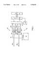
- FIG. 1is a schematic diagram of a disk drive apparatus according to an embodiment of this invention.
- FIGS. 2A, 2B and 2Care diagrams showing states of operation in a disk drive apparatus according to an embodiment of this invention.
- FIGS. 3A and 3Bare diagrams showing read signals in a disk drive apparatus according to an embodiment of this invention.
- FIG. 4is a flowchart showing a data recovery method according to an embodiment of this invention.
- FIG. 5is a block diagram showing a disk drive apparatus according to another embodiment of this invention.
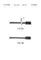
- FIGS. 6A and 6Bare top and side views, respectively, of a suspension structure according to yet another embodiment of this invention.
- FIG. 1shows a hard disk drive apparatus (HDD) according to an embodiment of this invention.
- the disk drive apparatus 10comprises a disk assembly 11 and hard disk controller (HDC) 30 containing a local CPU.
- the disk assembly 11comprises a disk drive (spindle motor) 14 which rotates a shaft 12 at a high speed.
- a cylindrical support structure 16is mounted on the shaft 12 in such a manner that they are concentric with each other.
- One or more data storage disks for 18A, 18Bare mounted on the outer surface of the supporting structure 16 at predetermined intervals. The disks 18A, 18B rotate together with the supporting structure 16 as one united body when the shaft 12 is rotated by the disk drive 14.
- Signal transducer heads 20A, 20B, 20C, 20Dare held by access arms 22A, 22B, 22C, 22D and face each disk surface, respectively.
- the access arms 22A, 22B, 22C, 22Dare connected to a signal transducer head drive (voice coil motor) 28 through a shaft 26.
- the signal transducer heads 20A, 20B, 20C, 20Dare positioned at a predetermined position by rotation of the shaft 26.
- the disk drive 14 and signal transducer head drive 28are connected to the HDC 30.
- the number of rotations and rotation speed of shaft 26are controlled by the HDC 30.
- the HDC 30can be connected to a host 32.
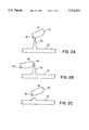
- FIGS. 2A, 2B and 2Cschematically show how a projection on a data recording surface of the disk is broken by contact with a positive pressure signal transducer head according to an embodiment of this invention.
- FIG. 2Ashows the state in which a signal transducer head 20 equipped with an MR head 42 contacts a projection 52 on the disk 18 while reading data on the disk 18.
- the signal transducer head 20includes the MR head 42 and an Air Bearing Surface (ABS) 44 holding the MR head 42.
- the signal transducer head 20is tilted with respect to the direction of rotation by air pressure produced by the rotation of the disk. This tilt angle is called the "pitch angle.”
- the pitch angleincreases as the number of disk rotations increases. It decreases as the number of disk rotations, and therefore wind pressure, decreases.
- the closest-to-disk point of the ABS 44 of the signal transducer head 20contacts the projection 52.
- FIG. 3Ashows this change in the read signal.
- the drastic change point 62 in the signal pattern that can be seen when the projection is detectedis caused by the temperature change of the MR head 42 and therefore ultimately by the projection 52.
- Such a projectioncauses a drastic change in temperature of the head's MR stripe, and is often called a thermal asperity.
- a read signal produced by a thermal asperityis distinct from normal data signals. Therefore, if a steep read signal which is likely to be caused by a thermal asperity is detected, a data recovery operation is performed.
- FIG. 2Bshows the positions of the disk 18 and signal transducer head 20 when the rate of disk rotation is decreased by the data recovery operation according to an embodiment of this invention.
- the flying height of the signal transducer head 20is lowered and comes closer to the disk 18.
- the pitch anglebecomes smaller. That is, the signal transducer head 20 comes nearer to a position parallel to the disk.
- the side of the ABS 44 of the signal transducer head 20hits the projection 52.
- the strikebreaks the projection 52 as shown in FIG. 2C.
- a reduced rotation speedis set to 2060 rpm.
- the signal transducer headis lowered until its closest point to the disk nearly contacts the surface of the disk.
- the lowered heightdepends on the shape and weight of the signal transducer head. It is desirable that an appropriate level is selected accordingly.
- the signal transducer headWhen the signal transducer head is lowered, it may remain in read mode or in the off state. For example, approximately 100 msec after the rotation speed reduction is started, the disk is brought into a low speed state, kept at this speed for 2 to 3 seconds, then returned to the normal rotation speed. After returning to the normal rotation speed, the read operation is performed again and the removal of the error is checked.
- the data recovery operationends with the break-off of the projection, i.e., thermal asperity, and the disk is returned to its normal rotation speed.
- the flying height of the signal transducer headincreases.
- FIG. 3Bshows the read signal after the data recovery operation. The steep signal change observed in FIG. 3A is eliminated, indicating that the projection (thermal asperity) has been removed.
- FIG. 4is a flowchart showing an error recovery method according to an embodiment of the present invention.
- the data error recovery processstarts at step 72.
- conventional error recovery processesfor example, bias current change of the MR head, AGC gain adjustment, or some other error recovery processes are performed.
- the datais re-read and if the data is read successfully, the operation exits the error recovery process routine (step 74) to return to the normal data read operation (step 79).
- the flying height of the signal transducer headis changed by changing the disk rotation speed in accordance with this embodiment of the invention.
- the disk speedis reduced, for example, from 4870 rpm to 2060 rpm as mentioned above.
- the normal rotation speedis returned (step 76).
- the datais re-read and if the data is read successfully, the error recovery process ends to return to the normal read operation (step 79). If the data read still fails, the error is reported as a hardware error to the host (step 78) and an appropriate action, such as data write to an alternative area, is performed.
- This embodimentuses a servo signal recorded on a disk to control the position of a signal transducer head to scrub and remove a projection, such as a thermal asperity.
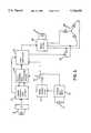
- FIG. 5is a block diagram that shows the main components of a disk drive apparatus of this embodiment.
- a servo signal detected by a magnetic head 71is amplified by a preamplifier 72, then a peak servo signal is detected and a pulse sequence is generated by a signal processing circuit 73. Based on this pulse sequence, a servo information processing circuit 74 detects a data identifier and generates a sample-and-hold timing.
- the clock used in this processis generated and supplied by a clock synthesizer 76, which generates any frequency, or by a crystal oscillator 78, which generates a frequency specific to a crystal oscillator element 77. Either clock synthesizer 76 or crystal oscillator 78 is selected by a change-over switch 79, which is activated by a local controller 75. That is, the switching is made according to a disk rotation speed.
- the local controller 75controls, via a motor driver 80, a current flowing into a voice coil motor (VCM) 81 to control the position of the head.
- VCMvoice coil motor
- Speed reduction of a spindle motor which drives a diskis accomplished by short-circuiting a switch 83 inserted between two different phases of a spindle motor 82 to apply a brake to the spindle motor 82.
- the speed reductionis accomplished in a short time.
- the revolution speed of the spindle motor 82is reduced, for example, to one half of the normal speed.
- the spindle motor 82is braked. The braking may be accomplished by applying short circuit between phases of the spindle motor 82 as described above, or by exciting the spindle motor 82 to bring it to a phase opposite to a normal phase.
- the servo clock supply sourceis switched from the crystal oscillator 78 to the clock synthesizer 76.
- the output frequency of the clock synthesizer 76is preset to one half of the frequency of a normal servo clock, that is, the servo clock based on the crystal oscillator 78.
- the magnetic head 71Under the conditions allowing servo data on the disk to be read, the magnetic head 71 is positioned over a track on which an error occurs and moved forward and backward, for example +/-50 tracks, from that track to make the ABS side of the signal transducer head scrub away a projection, such as a thermal asperity.
- the servo data read from the disk during this operationenables the signal transducer head to be positioned accurately for scrubbing.
- the disk rotation speedAfter scrubbing for a predetermined period of time, the disk rotation speed is returned to a normal speed, the servo clock supply source is switched back to the crystal oscillator 78, and then a read/wlite operation is retried.
- the signal transducer headperforms the scrubbing operation while reading servo data, accurate control can be achieved. For example, it can be moved 50 tracks inward or outward from a track on which an error occurred.
- the movement of the signal transducer headmay be controlled by specifying X tracks inward or outward as the target tracks, or by specifying the number of tracks to be skipped.
- the signal transducer headmay be moved one track for one disk rotation or several tracks for one disk rotation.
- an alternative area on the diskmay be used instead of the erroneous track by changing the address to ensure the reliability of subsequent data read/write operations.
- a bimetal element and a heating elementare attached to a head suspension, which is a mounting structure of a signal transducer head. If the disk drive apparatus detects an error, it heats the heating element on the suspension while the element is in the proximity of a track on which the error occurred. Heat from the heating element flexes the bimetal element to force the signal transducer head to reduce its flying height. While the flying height being reduced, the signal transducer head traverses the disk to scrub away a projection, such as a thermal asperity.
- FIGS. 6A and 6Bare top and side views, respectively, of a suspension having a bimetal element according to this embodiment.
- the suspension 91 fixed on a head arm 99comprises of a bimetal element, that is, an element formed of a first material 92 with a higher linear thermal expansion coefficient, for example SUS 303, and a second material 93 with a lower linear thermal expansion coefficient, for example SUS 406, bonded together.
- a heating element 94is formed on the material 93 of the suspension by printing a resistance element made of a material such as carbon. The heating can be controlled by a DC voltage source 96 and a switch 95. When the switch 95 is closed, electric current is conducted through the heating element and a difference between the linear coefficients of the two materials causes the suspension to flex. This, in turn, moves a signal transducer head 97 close to a disk 98, causing the flying height of the signal transducer head 97 to decrease.
Landscapes
- Supporting Of Heads In Record-Carrier Devices (AREA)
Abstract
Description
Claims (15)
Applications Claiming Priority (2)
| Application Number | Priority Date | Filing Date | Title |
|---|---|---|---|
| JP07242832AJP3098405B2 (en) | 1995-04-20 | 1995-09-21 | Disk device and method for recovering from read failure in disk device |
| JP7-242832 | 1995-09-21 |
Publications (1)
| Publication Number | Publication Date |
|---|---|
| US5754355Atrue US5754355A (en) | 1998-05-19 |
Family
ID=17094961
Family Applications (1)
| Application Number | Title | Priority Date | Filing Date |
|---|---|---|---|
| US08/633,596Expired - LifetimeUS5754355A (en) | 1995-09-21 | 1996-04-17 | Disk drive apparatus and read error recovery method in a disk drive apparatus |
Country Status (1)
| Country | Link |
|---|---|
| US (1) | US5754355A (en) |
Cited By (29)
| Publication number | Priority date | Publication date | Assignee | Title |
|---|---|---|---|---|
| US5880899A (en)* | 1997-02-25 | 1999-03-09 | International Business Machines Corporation | Removal of raised irregularities on a data storage disk with controlled abrasion by a magnetoresistive head |
| US5898535A (en)* | 1996-06-24 | 1999-04-27 | Kabushiki Kaisha Toshiba | Method and apparatus for recording and reproducing data in and from a data sector even when thermal asperity occurs in the servo area |
| US5917670A (en)* | 1996-10-15 | 1999-06-29 | Quantum Corporation | Method for recovering data from disk with magneto-resistive head in presence of thermal asperities |
| US5991121A (en)* | 1997-02-24 | 1999-11-23 | Fujitsu Limited | Head assembly having short circuit pattern short-circuiting a pair of lead lines |
| US6032276A (en)* | 1996-12-12 | 2000-02-29 | Samsung Electronics Co., Ltd | Apparatus and method for reading data from a disk type recording media |
| US6040953A (en)* | 1997-03-25 | 2000-03-21 | International Business Machines Corporation | Adaptive data recovery method and means tuned to thermal asperities in a cyclic, multitracked magnetic storage subsystem |
| US6049439A (en)* | 1996-03-12 | 2000-04-11 | International Business Machines Corporation | Data error recovery using reduced speed |
| US6084733A (en)* | 1996-10-25 | 2000-07-04 | International Business Machines Corporation | Storage device and error recovery method executing a plurality of error recovery routines based on error type |
| US6119261A (en)* | 1998-03-17 | 2000-09-12 | Quantum Corporation | Method for recovering data from disk with a dynamic erasure offset ECC data recovery protocol |
| US6181520B1 (en)* | 1997-07-04 | 2001-01-30 | Fujitsu Limited | Head slider and disk unit having contact detection means |
| US6297937B1 (en)* | 1998-02-24 | 2001-10-02 | Seagate Technology Llc | Suspension with adjustable preload |
| US6335842B1 (en)* | 1997-08-20 | 2002-01-01 | Nec Corporation | Magnetic recording apparatus with a head error detection circuit |
| US20020032881A1 (en)* | 2000-08-04 | 2002-03-14 | Ng Teckhock | Retrieval of a single complete copy from multiple stored copies of information |
| US6396651B1 (en) | 1999-07-12 | 2002-05-28 | Deanne S. Grover | Gear-shifting compensation system and method for nonlinear input elements |
| US6419551B1 (en) | 2001-06-21 | 2002-07-16 | International Business Machines Corporation | High speed burnishing of asperities in a disk drive |
| US6446236B1 (en) | 1999-10-13 | 2002-09-03 | Maxtor Corporation | Reading encoded information subject to random and transient errors |
| US6490408B1 (en)* | 1997-10-28 | 2002-12-03 | Lg Electronics Inc. | Apparatus and method for determining ID information recorded on an information-stored medium |
| US6583963B2 (en)* | 1997-10-07 | 2003-06-24 | Seagate Technology Llc | Apparatus to improve shock capability of disc drives |
| US20030133013A1 (en)* | 2002-01-15 | 2003-07-17 | Elmo Company, Limited | Imaging apparatus |
| US6600635B2 (en)* | 2001-03-09 | 2003-07-29 | Hitachi Global Storage Technologies Netherlands B.V. | Combined magnetic data and burnish head for magnetic recording |
| US20040100722A1 (en)* | 2002-11-25 | 2004-05-27 | Renesas Technology Corp. | Magnetic disk storage system |
| US6952330B1 (en)* | 1999-06-11 | 2005-10-04 | Seagate Technology Llc | Dynamic flying attitude control using augmented gimbal |
| US7023645B1 (en)* | 2002-05-03 | 2006-04-04 | Maxtor Corporation | Read error recovery method and apparatus |
| US7027251B1 (en) | 2002-01-04 | 2006-04-11 | Maxtor Corporation | Method and apparatus to control pole tip protrusion |
| US7224548B1 (en) | 2002-01-04 | 2007-05-29 | Maxtor Corporation | Determining contact write current in disk drive using position error signal variance |
| US20070174664A1 (en)* | 2006-01-04 | 2007-07-26 | Ess Data Recovery, Inc. | Data recovery application |
| US20080180845A1 (en)* | 2007-01-31 | 2008-07-31 | Albert Wallash | Slider air bearing for disk drives |
| US20080239572A1 (en)* | 2007-03-27 | 2008-10-02 | Sae Magnetics (H.K) Ltd. | Suspension with bi-layer flexure base |
| US8753316B2 (en) | 2006-10-17 | 2014-06-17 | Tandem Diabetes Care, Inc. | Insulin pump for determining carbohydrate consumption |
Citations (11)
| Publication number | Priority date | Publication date | Assignee | Title |
|---|---|---|---|---|
| EP0010594A1 (en)* | 1978-11-02 | 1980-05-14 | Boge GmbH | Flexible coupling, especially steering column coupling for vehicles |
| JPS5644123A (en)* | 1979-09-18 | 1981-04-23 | Nippon Telegr & Teleph Corp <Ntt> | Floating head slider |
| US4635139A (en)* | 1985-08-26 | 1987-01-06 | International Business Machines Corporation | Asperity burst writer |
| US4669011A (en)* | 1985-05-03 | 1987-05-26 | Eastman Kodak Company | Slider assembly with dynamically positionable transducer |
| JPS62184679A (en)* | 1986-02-10 | 1987-08-13 | Fujitsu Ltd | Head burnish system |
| JPH0528472A (en)* | 1991-07-19 | 1993-02-05 | Matsushita Electric Ind Co Ltd | Burning method of magnetic disk |
| US5233482A (en)* | 1991-07-31 | 1993-08-03 | International Business Machines Corporation | Thermal asperity compensation for PRML data detection |
| US5461521A (en)* | 1991-10-17 | 1995-10-24 | Ricoh Company, Ltd. | Magnetic disk unit control method for removing dust from a disk |
| US5527110A (en)* | 1993-04-30 | 1996-06-18 | International Business Machines Corporation | Method and apparatus for detecting asperities on magnetic disks using thermal proximity imaging |
| US5537034A (en)* | 1995-05-19 | 1996-07-16 | Quantum Corporation | Method for mapping thermal asperities of a magnetic recording surface in data storage device |
| US5612830A (en)* | 1992-03-25 | 1997-03-18 | International Business Machines Corporation | Method and apparatus for cleaning disks upon reaching a disk drive start-stop cycle threshold |
- 1996
- 1996-04-17USUS08/633,596patent/US5754355A/ennot_activeExpired - Lifetime
Patent Citations (11)
| Publication number | Priority date | Publication date | Assignee | Title |
|---|---|---|---|---|
| EP0010594A1 (en)* | 1978-11-02 | 1980-05-14 | Boge GmbH | Flexible coupling, especially steering column coupling for vehicles |
| JPS5644123A (en)* | 1979-09-18 | 1981-04-23 | Nippon Telegr & Teleph Corp <Ntt> | Floating head slider |
| US4669011A (en)* | 1985-05-03 | 1987-05-26 | Eastman Kodak Company | Slider assembly with dynamically positionable transducer |
| US4635139A (en)* | 1985-08-26 | 1987-01-06 | International Business Machines Corporation | Asperity burst writer |
| JPS62184679A (en)* | 1986-02-10 | 1987-08-13 | Fujitsu Ltd | Head burnish system |
| JPH0528472A (en)* | 1991-07-19 | 1993-02-05 | Matsushita Electric Ind Co Ltd | Burning method of magnetic disk |
| US5233482A (en)* | 1991-07-31 | 1993-08-03 | International Business Machines Corporation | Thermal asperity compensation for PRML data detection |
| US5461521A (en)* | 1991-10-17 | 1995-10-24 | Ricoh Company, Ltd. | Magnetic disk unit control method for removing dust from a disk |
| US5612830A (en)* | 1992-03-25 | 1997-03-18 | International Business Machines Corporation | Method and apparatus for cleaning disks upon reaching a disk drive start-stop cycle threshold |
| US5527110A (en)* | 1993-04-30 | 1996-06-18 | International Business Machines Corporation | Method and apparatus for detecting asperities on magnetic disks using thermal proximity imaging |
| US5537034A (en)* | 1995-05-19 | 1996-07-16 | Quantum Corporation | Method for mapping thermal asperities of a magnetic recording surface in data storage device |
Non-Patent Citations (4)
| Title |
|---|
| IBM Technical Disclosure Bulletin, vol. 34, No. 11, Apr. 1992, pp. 217 219, Fast Offset Recovery for Thermal Asperity Data Recovery Procedure.* |
| IBM Technical Disclosure Bulletin, vol. 34, No. 11, Apr. 1992, pp. 217-219, Fast Offset Recovery for Thermal Asperity Data Recovery Procedure. |
| Patent Abstracts of Japan, vol. 17, No. 311, P 1556, Jun. 14, 1993.* |
| Patent Abstracts of Japan, vol. 17, No. 311, P-1556, Jun. 14, 1993. |
Cited By (39)
| Publication number | Priority date | Publication date | Assignee | Title |
|---|---|---|---|---|
| US6049439A (en)* | 1996-03-12 | 2000-04-11 | International Business Machines Corporation | Data error recovery using reduced speed |
| US5898535A (en)* | 1996-06-24 | 1999-04-27 | Kabushiki Kaisha Toshiba | Method and apparatus for recording and reproducing data in and from a data sector even when thermal asperity occurs in the servo area |
| US5917670A (en)* | 1996-10-15 | 1999-06-29 | Quantum Corporation | Method for recovering data from disk with magneto-resistive head in presence of thermal asperities |
| US6084733A (en)* | 1996-10-25 | 2000-07-04 | International Business Machines Corporation | Storage device and error recovery method executing a plurality of error recovery routines based on error type |
| US6032276A (en)* | 1996-12-12 | 2000-02-29 | Samsung Electronics Co., Ltd | Apparatus and method for reading data from a disk type recording media |
| US5991121A (en)* | 1997-02-24 | 1999-11-23 | Fujitsu Limited | Head assembly having short circuit pattern short-circuiting a pair of lead lines |
| US5880899A (en)* | 1997-02-25 | 1999-03-09 | International Business Machines Corporation | Removal of raised irregularities on a data storage disk with controlled abrasion by a magnetoresistive head |
| US6040953A (en)* | 1997-03-25 | 2000-03-21 | International Business Machines Corporation | Adaptive data recovery method and means tuned to thermal asperities in a cyclic, multitracked magnetic storage subsystem |
| US6181520B1 (en)* | 1997-07-04 | 2001-01-30 | Fujitsu Limited | Head slider and disk unit having contact detection means |
| US6335842B1 (en)* | 1997-08-20 | 2002-01-01 | Nec Corporation | Magnetic recording apparatus with a head error detection circuit |
| US6583963B2 (en)* | 1997-10-07 | 2003-06-24 | Seagate Technology Llc | Apparatus to improve shock capability of disc drives |
| US6490408B1 (en)* | 1997-10-28 | 2002-12-03 | Lg Electronics Inc. | Apparatus and method for determining ID information recorded on an information-stored medium |
| US6297937B1 (en)* | 1998-02-24 | 2001-10-02 | Seagate Technology Llc | Suspension with adjustable preload |
| US6119261A (en)* | 1998-03-17 | 2000-09-12 | Quantum Corporation | Method for recovering data from disk with a dynamic erasure offset ECC data recovery protocol |
| US6952330B1 (en)* | 1999-06-11 | 2005-10-04 | Seagate Technology Llc | Dynamic flying attitude control using augmented gimbal |
| US6396651B1 (en) | 1999-07-12 | 2002-05-28 | Deanne S. Grover | Gear-shifting compensation system and method for nonlinear input elements |
| US6446236B1 (en) | 1999-10-13 | 2002-09-03 | Maxtor Corporation | Reading encoded information subject to random and transient errors |
| US20020032881A1 (en)* | 2000-08-04 | 2002-03-14 | Ng Teckhock | Retrieval of a single complete copy from multiple stored copies of information |
| US6941488B2 (en) | 2000-08-04 | 2005-09-06 | Seagate Technology Llc | Retrieval of a single complete copy from multiple stored copies of information |
| US6600635B2 (en)* | 2001-03-09 | 2003-07-29 | Hitachi Global Storage Technologies Netherlands B.V. | Combined magnetic data and burnish head for magnetic recording |
| US6419551B1 (en) | 2001-06-21 | 2002-07-16 | International Business Machines Corporation | High speed burnishing of asperities in a disk drive |
| US7027251B1 (en) | 2002-01-04 | 2006-04-11 | Maxtor Corporation | Method and apparatus to control pole tip protrusion |
| US7224548B1 (en) | 2002-01-04 | 2007-05-29 | Maxtor Corporation | Determining contact write current in disk drive using position error signal variance |
| US20030133013A1 (en)* | 2002-01-15 | 2003-07-17 | Elmo Company, Limited | Imaging apparatus |
| US7372503B2 (en)* | 2002-01-15 | 2008-05-13 | Elmo Company Limited | Imaging apparatus |
| US7023645B1 (en)* | 2002-05-03 | 2006-04-04 | Maxtor Corporation | Read error recovery method and apparatus |
| US7158332B2 (en) | 2002-11-25 | 2007-01-02 | Renesas Technology Corp. | Magnetic disk storage system |
| US20060072237A1 (en)* | 2002-11-25 | 2006-04-06 | Renesas Technology Corp. | Magnetic disk storage system |
| US20040100722A1 (en)* | 2002-11-25 | 2004-05-27 | Renesas Technology Corp. | Magnetic disk storage system |
| US7054089B2 (en)* | 2002-11-25 | 2006-05-30 | Renesas Technology Corp. | Magnetic disk storage system |
| US20070174664A1 (en)* | 2006-01-04 | 2007-07-26 | Ess Data Recovery, Inc. | Data recovery application |
| US8753316B2 (en) | 2006-10-17 | 2014-06-17 | Tandem Diabetes Care, Inc. | Insulin pump for determining carbohydrate consumption |
| US8961465B2 (en) | 2006-10-17 | 2015-02-24 | Tanden Diabetes Care, Inc. | Insulin pump having a food database |
| US8998878B2 (en) | 2006-10-17 | 2015-04-07 | Tandem Diabetes Care, Inc. | Insulin pump having correction factors |
| US11217339B2 (en) | 2006-10-17 | 2022-01-04 | Tandem Diabetes Care, Inc. | Food database for insulin pump |
| US12170136B2 (en) | 2006-10-17 | 2024-12-17 | Tandem Diabetes Care, Inc. | Insulin pump having basal rate testing features |
| US20080180845A1 (en)* | 2007-01-31 | 2008-07-31 | Albert Wallash | Slider air bearing for disk drives |
| US20080239572A1 (en)* | 2007-03-27 | 2008-10-02 | Sae Magnetics (H.K) Ltd. | Suspension with bi-layer flexure base |
| US7957104B2 (en) | 2007-03-27 | 2011-06-07 | Sae Magnetics (Hk) Ltd. | Suspension with bi-layer flexure base whose layers have different coefficients of thermal expansion to eliminate thermally induced flying height variations |
Similar Documents
| Publication | Publication Date | Title |
|---|---|---|
| US5754355A (en) | Disk drive apparatus and read error recovery method in a disk drive apparatus | |
| US6122131A (en) | Adaptively-controlled disk drive assembly | |
| JP2878257B2 (en) | Magnetic data storage device and method for removing protrusions on disk surface | |
| JP3273502B2 (en) | Disk drive device, disk drive error recovery method, and disk drive control device | |
| US6781780B1 (en) | Method and system for preventing data loss from an off-track write condition in a disk drive by rewriting data buffered from an adjacent track | |
| CN1074565C (en) | Disk drive with shock detection based on thermoresistive signal from magnetoresistive head | |
| US6798605B2 (en) | Magnetic disk apparatus and method of controlling the same | |
| US6061805A (en) | Method for executing an error recovery procedure | |
| US5696643A (en) | Disk drive apparatus and read error recovery method in a disk drive apparatus | |
| US6519109B1 (en) | Method and apparatus for providing feedforward control of two interacting actuators | |
| JP3046529B2 (en) | Magnetic recording device | |
| US6760174B2 (en) | Adaptive fly height for error recovery in a disc drive | |
| JP4131950B2 (en) | Rotating disk storage device | |
| US7023645B1 (en) | Read error recovery method and apparatus | |
| JPH10162494A (en) | Error recoverying method | |
| JPH1125625A (en) | Disk drive device, load/unload device and its control method | |
| JP2006309822A (en) | Magnetic disk apparatus and recording method | |
| EP0739007B1 (en) | A disk drive apparatus and read error recovery process for a disk drive apparatus | |
| US7184241B1 (en) | Disk drive that performs cold writes to erased buffer | |
| JP2908741B2 (en) | Disk device and method for recovering from read failure in disk device | |
| JPH0935397A (en) | Disk device and read-defect recovery method in disk device | |
| US6690532B1 (en) | Self-diagnostic MR head recovery | |
| JP3836651B2 (en) | Disk storage | |
| JP2001067765A (en) | Magnetic disk drive and control method therefor | |
| US7298572B2 (en) | Fly height adjusted sweep cycle for a disc drive |
Legal Events
| Date | Code | Title | Description |
|---|---|---|---|
| AS | Assignment | Owner name:INTERNATIONAL BUSINESS MACHINES CORPORATION, NEW Y Free format text:ASSIGNMENT OF ASSIGNORS INTEREST;ASSIGNORS:NAKAMURA, TAKASHI;YONEDA, ISAO;YOKOE, YUJI;AND OTHERS;REEL/FRAME:008005/0821;SIGNING DATES FROM 19960530 TO 19960603 | |
| STCF | Information on status: patent grant | Free format text:PATENTED CASE | |
| FEPP | Fee payment procedure | Free format text:PAYOR NUMBER ASSIGNED (ORIGINAL EVENT CODE: ASPN); ENTITY STATUS OF PATENT OWNER: LARGE ENTITY | |
| FPAY | Fee payment | Year of fee payment:4 | |
| AS | Assignment | Owner name:MARIANA HDD B.V., NETHERLANDS Free format text:ASSIGNMENT OF ASSIGNORS INTEREST;ASSIGNOR:INTERNATIONAL BUSINESS MACHINES CORPORATION;REEL/FRAME:013663/0348 Effective date:20021231 | |
| AS | Assignment | Owner name:HITACHI GLOBAL STORAGE TECHNOLOGIES NETHERLANDS B. Free format text:CHANGE OF NAME;ASSIGNOR:MARIANA HDD B.V.;REEL/FRAME:013746/0146 Effective date:20021231 | |
| FEPP | Fee payment procedure | Free format text:PAYOR NUMBER ASSIGNED (ORIGINAL EVENT CODE: ASPN); ENTITY STATUS OF PATENT OWNER: LARGE ENTITY Free format text:PAYER NUMBER DE-ASSIGNED (ORIGINAL EVENT CODE: RMPN); ENTITY STATUS OF PATENT OWNER: LARGE ENTITY | |
| FPAY | Fee payment | Year of fee payment:8 | |
| FPAY | Fee payment | Year of fee payment:12 | |
| AS | Assignment | Owner name:HGST, NETHERLANDS B.V., NETHERLANDS Free format text:CHANGE OF NAME;ASSIGNOR:HGST, NETHERLANDS B.V.;REEL/FRAME:029341/0777 Effective date:20120723 Owner name:HGST NETHERLANDS B.V., NETHERLANDS Free format text:CHANGE OF NAME;ASSIGNOR:HITACHI GLOBAL STORAGE TECHNOLOGIES NETHERLANDS B.V.;REEL/FRAME:029341/0777 Effective date:20120723 | |
| AS | Assignment | Owner name:WESTERN DIGITAL TECHNOLOGIES, INC., CALIFORNIA Free format text:ASSIGNMENT OF ASSIGNORS INTEREST;ASSIGNOR:HGST NETHERLANDS B.V.;REEL/FRAME:040818/0551 Effective date:20160831 |