US5753947A - Very high-density DRAM cell structure and method for fabricating it - Google Patents
Very high-density DRAM cell structure and method for fabricating itDownload PDFInfo
- Publication number
- US5753947A US5753947AUS08/390,295US39029595AUS5753947AUS 5753947 AUS5753947 AUS 5753947AUS 39029595 AUS39029595 AUS 39029595AUS 5753947 AUS5753947 AUS 5753947A
- Authority
- US
- United States
- Prior art keywords
- region
- semiconductor structure
- line
- epitaxial
- digit
- Prior art date
- Legal status (The legal status is an assumption and is not a legal conclusion. Google has not performed a legal analysis and makes no representation as to the accuracy of the status listed.)
- Expired - Lifetime
Links
Images


Classifications
- H—ELECTRICITY
- H10—SEMICONDUCTOR DEVICES; ELECTRIC SOLID-STATE DEVICES NOT OTHERWISE PROVIDED FOR
- H10B—ELECTRONIC MEMORY DEVICES
- H10B12/00—Dynamic random access memory [DRAM] devices
- H10B12/01—Manufacture or treatment
- H10B12/02—Manufacture or treatment for one transistor one-capacitor [1T-1C] memory cells
- H10B12/05—Making the transistor
- H10B12/053—Making the transistor the transistor being at least partially in a trench in the substrate
- H—ELECTRICITY
- H10—SEMICONDUCTOR DEVICES; ELECTRIC SOLID-STATE DEVICES NOT OTHERWISE PROVIDED FOR
- H10B—ELECTRONIC MEMORY DEVICES
- H10B12/00—Dynamic random access memory [DRAM] devices
- H10B12/30—DRAM devices comprising one-transistor - one-capacitor [1T-1C] memory cells
- H10B12/31—DRAM devices comprising one-transistor - one-capacitor [1T-1C] memory cells having a storage electrode stacked over the transistor
- H—ELECTRICITY
- H10—SEMICONDUCTOR DEVICES; ELECTRIC SOLID-STATE DEVICES NOT OTHERWISE PROVIDED FOR
- H10B—ELECTRONIC MEMORY DEVICES
- H10B12/00—Dynamic random access memory [DRAM] devices
- H10B12/30—DRAM devices comprising one-transistor - one-capacitor [1T-1C] memory cells
- H10B12/34—DRAM devices comprising one-transistor - one-capacitor [1T-1C] memory cells the transistor being at least partially in a trench in the substrate
Definitions
- the inventionrelates to a very high-density DRAM (dynamic random access memory) cell or other semiconductor structure having a series of vertically oriented access transistors (sometimes referred to as transfer gate transistors, and associated capacitors or other components.
- DRAMdynamic random access memory
- Many known prior art devicesrequired a horizontal transistor and a storage node on each side of the transistor. As a result, the surface area or "real estate" of the silicon was not optimally used.
- a vertical transistor semiconductor and method of making a vertical transistoris provided.
- the vertical transistoris particularly suited for use in a DRAM cell, however, the present invention may be utilized in a wide range of devices, particularly those in which a vertical access transistor and a cross-point array would be desirable.
- the structurepermits a DRAM cell to be fabricated with a comparatively low number of masking layers. For example, embodiments utilizing only four or five masking layers are disclosed.
- the vertical nature of the transistorallows a larger number of transistors per surface area compared to conventional techniques.
- the method and apparatusalso utilizes a buried digit line.
- the digit linemay include a portion that is a metal material that in a preferred embodiment is step-shaped sidewall of the digit line.
- the transistoris particular suited for use with a variety of DRAM capacitors.
- the present inventionmay include forming vertical transistors utilizing buried digit line.
- the digit linesmay be isolated from one another by a dielectric filled trench.
- a portion of the digit linemay include a refractory material.
- the refractory materialis formed in a step-shaped sidewall of the buried digit line. The refractory material provides a lowered resistance for the digit line.
- the present inventionmay also include utilizing a plurality of word lines by forming an epitaxial layer above the digit lines.
- the epitaxial layermay have alternating highly and lightly doped regions, for example P + and P - regions.
- a portion of the epitaxial layermay also be highly doped, for example N + , to form a storage node.
- An oxideis thermally grown adjacent the epitaxial layer to form a gate oxide.
- FIGS. 7(a), 7(b), 7(c), 7(d), 7(e), and 7(f)(where the latter three figures correspond to FIGS. 7(a), 7(b) and 7(c) in an alternative implementation); FIGS. 8(a) and 8(b) and, in an alternative implementation, FIGS. 8(d) and 8(e) (for consistency, FIG. 8(c) is not used); FIGS. 9 and 9A; FIGS. 10, 11, 12 (showing one implementation); FIGS. 10A, 11A, and 12A (showing an alternative implementation); FIG. 12B (showing another alternative implementation); FIGS. 13(a), 13(b), and 13(c); FIGS. 14(a) and 14(b); FIGS. 15, 16, 17, and 18; and FIG. 20 (showing yet another alternative implementation).
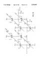
- FIG. 19is a schematic diagram showing one possible implementation of a cell array using a semiconductor structure in accordance with the invention.
- a semiconductor structure in accordance with the inventionincluding an access transistor, is described below in terms of some steps that may be used to fabricate an illustrative embodiment.
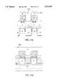
- FIG. 1An array area 100 for multiple semiconductor structures, e.g., DRAM cells, is to be implanted and the implant species is to be driven to a depth of about 0.25 microns to 0.5 microns on a substrate 105.
- the array area 100is doped with a conventional N + dopant such as arsenic or phosphorus, while the area of the substrate 105 outside the array area 100 is doped with a conventional P - dopant such as boron.
- the array areacan be doped with a P + dopant and the outside area with an N - dopant, with suitable changes being made in the fabrication process described below.
- FIG. 2An intermediate oxide layer shown as 205 is formed on the substrate 105 and a trenched area 210 is etched.
- the trenched areas 210will be filled and used as isolation structures as discussed in more detail below.
- the intermediate oxide layer 205may be formed by a variety of well-known deposition techniques such as chemical vapor deposition of TEOS (tetraethylorthosilicate) or NO (nitrous oxide), and the like. Alternatively, the intermediate oxide layer 205 may be thermally grown on the substrate 105 provided that appropriate precautions are taken to avoid oxidation of the N + dopant in the array area 100.
- TEOStetraethylorthosilicate
- NOnitrogen oxide
- a photoresist(not shown) is applied in a photolithography masking process and a dry anisotropic etch (sometimes known as a plasma etch) is performed to produce the trenched area 210.
- a dry anisotropic etch(sometimes known as a plasma etch) is performed to produce the trenched area 210.
- the trenched areais etched into the silicon to a depth of approximately 0.15 to 0.4 microns.
- the photoresistis stripped.
- the digit lines 215may extend outside the array area 100 into the P - portion of the substrate 105 to avoid shorting adjacent digit lines together.
- the oxide layer 205may be removed if desired.
- FIG. 3A refractory material 305 is conformally deposited to a thickness in the range of 500 ⁇ to 1000 ⁇ on the sides of the digit lines 215 after the process steps illustrated in FIG. 2(a).
- the refractory material 305can be, e.g., a metal such as tungsten, cobalt, titanium, tantalum, or other suitable material that can withstand the temperatures used in the fabrication process.
- the refractory materialis anisotropically etched with a reactive ion etch (RIE) to remove the material in the vertical direction only as shown in FIG. 3(a).
- RIEreactive ion etch
- FIG. 4A dry anisotropic RIE etch is performed in the trenched area 210 to etch another 0.3 to 0.5 micron trenched area 405 into the doped-substrate array area 100. It will be appreciated by those of ordinary skill that the desired depth of the intermediate oxide layer 205, deposited as described above, will vary with the selectivity of the etch chemistry and the depth of the trenched area 405 being etched. As a result, the digit line 215 has a step-like sidewall 415, the upper portion of which is covered by the refractory material 305.
- the bottom of the trenched area 405is then ion-implanted with a P-type material such as boron (using, e.g., a 25 keV implant in a dose ranging from 1 ⁇ 10 12 ions/cm 2 to 5 ⁇ 10 12 ions/cm 2 ) to form a channel stop 410.
- a P-type materialsuch as boron
- FIGS. 5, 6The trenched area 405 is conventionally filled with a conformal deposition of a dielectric such as TEOS, shown as reference numeral 510.
- a dielectricsuch as TEOS
- the trenched areawill be somewhat overfilled to the level identified with reference numeral 505 and planarized using an etch or a chemical-mechanical planarization (CMP) back to a desired depth, e.g., to the level of the surface 605.
- CMPchemical-mechanical planarization
- the oxide layer 205is removed from the digit lines 215, and the digit lines 215 are separated by trenches (reference numeral 405 is used hereafter to identify the filled trench).
- another oxide layer 620may be deposited on the substrate and then contact openings 630 formed as shown in FIG. 6.
- the after planarization oxide surface level 605may be left at a depth equivalent to the top of the oxide layer 620 and the contact openings then formed.
- FIG. 5Ashows an alternative embodiment in which a comparatively thick layer 510 of a TEOS insulating oxide layer is deposited on the substrate. As shown in FIG. 6A, the depth of the insulating oxide layer is then reduced to that shown as reference numeral 610.
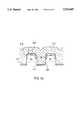
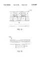
- FIG. 7An epitaxial layer 705, e.g., of silicon doped with a P - dopant at a concentration in the range of 10 15 atoms/cc to 10 16 atoms/cc, is deposited on the substrate 105 to achieve a thickness t of approximately 0.6 to 1.2 microns, preferably 0.8 to 1.2 microns.
- the epitaxial layeris subsequently patterned with a photoresist 710 and anisotropically dry-etched to leave pillar-like word lines (identified for convenience by reference numeral 705) which are perpendicular to the digit lines 215 as shown in FIGS. 7(b) and 7(c).
- the photoresist 710is then removed using conventional techniques.
- This epitaxial layerserves as the foundation for a vertical transistor as discussed below.
- the oxide 205 over the N + digit lineis removed with a RIE etch patterned to create contact openings above the digit lines 215. Subsequently, the contact openings are filled with a selective epitaxial silicon layer 715 that is doped N + .
- the oxide layer 510is left remaining above trench area 405.
- Epitaxial layer 705 and photoresist 710are then deposited and patterned as described above. Though shown as centered in FIG. 7(d), the contact opening portion 715 can be positioned off-center so that it can favor a one-sided transistor action.
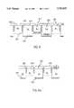
- FIG. 8A first portion 805 of an insulator oxide layer is thermally grown on the word lines 705.
- An angled implant for adjustment of threshold voltage V Tcan be applied in the usual manner.
- the first portionmay be in the range of 100 ⁇ to 500 ⁇ . depending on the trade-offs desired in the particular implementation characteristics, e.g., speed of deposition, desired capacitance, and the like.
- the alternative embodiment discussed above in connection with FIGS. 5A and 6A and FIGS. 7(d), (e), and (f)is shown at this stage in FIGS. 8(d) and 8(e) and in FIG. 9A.
- the oxidecould be deposited so that on opposite sides of the word line 705 the oxide layer 805 is comparatively thick and comparatively thin respectively. This allows the transistor being formed to operate on one side only of the device, thus reducing the chance that the depletion regions on opposite sides of the word line will overlap.
- FIGS. 9, 10A polysilicon layer is conformally deposited on the substrate 105, shown as reference numeral 905.
- the polysilicon layeris doped in situ with an N - dopant such as arsenic or phosphorus to a concentration in the range of 10 20 to 10 21 atoms per cubic centimeter.
- the polysilicon layeris planarized using an RIE etch or a chemical-mechanical planarization to the level of the insulator oxide layer 805, shown as reference numeral 1005.
- the polysilicon planarizationcan be stopped at a suitable thickness above the word line 705 as shown in FIG. 10(a).
- the polysiliconis then oxidized as shown in FIG. 11(a) to form an oxide layer that is approximately 2,000 ⁇ , after which an opening 1205 is formed as described below.
- FIG. 11A second portion 1105 of the insulator oxide layer is deposited to a thickness in the range of 2,000 ⁇ to 3,000 ⁇ using chemical vapor deposition or other suitable method.
- the second portion 1105functions as both an implant mask and an insulator for subsequent steps.
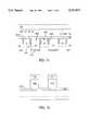
- FIGS. 12, 13Openings 1205 are etched through the first portion 805 and the second portion 1105 of the insulator oxide layer above each to serve as contact holes for the word lines 705.
- An N - dopant materialis implanted through the openings 1205 onto the word lines 705.
- a polysilicon layeris deposited on the substrate 105 with in-situ doping of an N + material, followed by a patterned anisotropic etch. This results in the formation of a storage node 1310 having vertical sidewalls 1305.
- the desired shape and thickness of polysilicon layer 1310will vary depending on the type of capacitor to be fabricated therein as discussed below.
- FIG. 12Aillustrates the opening 1205 when the alternative implementation shown in FIGS. 10A and 11A is utilized. As noted above in connection with the contact opening portion 715, the openings 1205 can be positioned off-center so that they can favor a one-sided transistor action.
- FIG. 14A photoresist layer 1405 is coated on the substrate 105 and patterned as shown in FIGS. 14(a) and 14(b).
- the oxide in region 1410is etched with an REI etch.
- a P + implantis performed in region 1410.
- the P + implantshould not have so much lateral straggle that it will go too far into the P-minus region.
- the dose and energy of the P + implantshould be selected to (1) minimize lateral implant straggle, (2) minimize propagation delays in the word line, and (3) minimize storage node diode leakage; the P + implant preferably will be a medium-energy implant in the range of 50 to 200 keV.
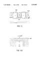
- an oxide 1505 fill and etchback planarization processis performed to produce the structure shown in FIG. 15.
- a variety of types of capacitorscan be used; three representative capacitor types (planar, finned, and container) are shown for illustrative purposes in FIGS. 16 through 18.
- several dielectric materialsare depicted (TaO 5 , PZT, and ONO); virtually any standard dielectric may be used in the capacitor.
- the structure described aboveresults in an array depicted schematically in FIG. 19.
- the wordlines WL1 through WL4are composed of lines with alternating P+ and P- regions where the P- region is the substrate for the access transistor.
- two transistorsare shown on each side of the array for two-transistor operation; as discussed above, however, a one-transistor operation may be favored by placement of the word line and/or the contact opening.
- each digit linehas its own parasitic capacitance capacitor.
- the wordline voltagemay range from 0 to -VCC, while the digit line voltage may range from 0 to VCC.
- the backbias voltage(Vbb) controls the turn-on voltage of the access transistor gate.
- a zero voltage on the backbiasresults in a lower turn-on voltage
- -5V on the backbiasresults in a higher turn-on voltage.
- Vbb-5V is the off state.
- the illustrative structurepermits a cell to be fabricated with a comparatively low number of masks.
- the alternative processes described aboverequire four and five masks respectively.
- the use of a buried digit lineeliminates the need for double-level metal.
- the poly gateis a CMP poly layer, this further eliminates the need for a poly gate masking layer.
- the vertical nature of the transistors described abovepermits longer transistor lengths for comparable transistor densities, thus reducing the likelihood of short-channel transistor effects.
- a vertical transistor acting as an access transistor gate to the DRAM cell capacitordoes require that the access current charge leakage through the access gate claimed to be less than 0.1 pA when the transistor is shut off.
- the DRAM access transistordoes not need to be a high drive device so that the turn-off voltage of the access gate can be higher than the periphery devices, thus allowing for better shut-off.
- the illustrative embodiments described aboveuse the body of the transistor as the controlling element in the transistor.
- the epitaxial silicon which becomes the substrate of the vertical access devicewill have the backbias potential V BB that sets the threshold voltage V T of the device.
- the more negative backbias voltage V BBwill give a higher threshold voltage V T .
- V Tthe threshold voltage
- V GSthe gate-to-source potential
- the source potential V GSexceeds the threshold voltage V T
- the deviceis conductive.
- the amount of charge necessary to set the backbias voltage V BBis selected to conduct readily to all the string of parallel rowline transistors.
- the backbias voltage V BBneeds to reach its potential to turn on the access gate in time as the digitlines are sensed as the cell capacitor charge is dumped into the digitline.
- the epitaxial silicon layerhas P + regions between cells. The P + lowers the resistance and also improves the isolation between the cells. Also, the P + must not intersect the storage mode diode so that the diode leakage must be maintained at the lowest level. The level of the resistance will dictate how much current drive the rowline drivers will need to supply which means that the size of rowline drivers would be increased.
- the P +can be also incorporated on non-active side of the vertical transistor (see FIG. 1) so that the P + would be continuous throughout the rowline.
- FIG. 20illustrates a continuous P + area 2000 incorporated into the rowline.
- the vertical-gate transistor described abovecan be used not only in conjunction with a capacitor in a DRAM, but in a wide range of devices in which a vertical access transistor and a cross-point array configuration would be desirable.
- an antifuse devicecan be constructed above the storage node diode depicted in the illustrative embodiment.
- a programmable resistor devicecan be constructed in a similar manner.
- a vertically-integrated semiconductor structure in accordance with the present inventionpermits the number of transistors to be increased by approximately a factor of three for the same surface area.
- a given transistor densityis achievable with much wider tolerances in photolithography and thus at significantly lower cost.
- Vertical integrationis considerably easier using the techniques described above, and allows a wider variety of capacitor designs, including capacitors based on ferroelectric properties.
- the illustrative semiconductor structurehas very good static refresh characteristics.
- the time between refresh cyclesis advantageously increased because of the reduced leakage from the storage node 1310 to the silicon substrate 104.
- the illustrative semiconductor structurealso has excellent standby current characteristics.
Landscapes
- Engineering & Computer Science (AREA)
- Manufacturing & Machinery (AREA)
- Semiconductor Memories (AREA)
Abstract
Description
Claims (20)
Priority Applications (2)
| Application Number | Priority Date | Filing Date | Title |
|---|---|---|---|
| US08/390,295US5753947A (en) | 1995-01-20 | 1995-01-20 | Very high-density DRAM cell structure and method for fabricating it |
| US08/920,328US6096596A (en) | 1995-01-20 | 1997-08-21 | Very high-density DRAM cell structure and method for fabricating it |
Applications Claiming Priority (1)
| Application Number | Priority Date | Filing Date | Title |
|---|---|---|---|
| US08/390,295US5753947A (en) | 1995-01-20 | 1995-01-20 | Very high-density DRAM cell structure and method for fabricating it |
Related Child Applications (1)
| Application Number | Title | Priority Date | Filing Date |
|---|---|---|---|
| US08/920,328DivisionUS6096596A (en) | 1995-01-20 | 1997-08-21 | Very high-density DRAM cell structure and method for fabricating it |
Publications (1)
| Publication Number | Publication Date |
|---|---|
| US5753947Atrue US5753947A (en) | 1998-05-19 |
Family
ID=23541904
Family Applications (2)
| Application Number | Title | Priority Date | Filing Date |
|---|---|---|---|
| US08/390,295Expired - LifetimeUS5753947A (en) | 1995-01-20 | 1995-01-20 | Very high-density DRAM cell structure and method for fabricating it |
| US08/920,328Expired - LifetimeUS6096596A (en) | 1995-01-20 | 1997-08-21 | Very high-density DRAM cell structure and method for fabricating it |
Family Applications After (1)
| Application Number | Title | Priority Date | Filing Date |
|---|---|---|---|
| US08/920,328Expired - LifetimeUS6096596A (en) | 1995-01-20 | 1997-08-21 | Very high-density DRAM cell structure and method for fabricating it |
Country Status (1)
| Country | Link |
|---|---|
| US (2) | US5753947A (en) |
Cited By (39)
| Publication number | Priority date | Publication date | Assignee | Title |
|---|---|---|---|---|
| US5977579A (en)* | 1998-12-03 | 1999-11-02 | Micron Technology, Inc. | Trench dram cell with vertical device and buried word lines |
| FR2779273A1 (en)* | 1998-05-27 | 1999-12-03 | Samsung Electronics Co Ltd | SEMICONDUCTOR MEMORY DEVICE HAVING SOI (SILICON ON INSULATOR) STRUCTURE AND METHOD FOR MANUFACTURING SAME |
| US6072209A (en)* | 1997-07-08 | 2000-06-06 | Micro Technology, Inc. | Four F2 folded bit line DRAM cell structure having buried bit and word lines |
| US6150687A (en)* | 1997-07-08 | 2000-11-21 | Micron Technology, Inc. | Memory cell having a vertical transistor with buried source/drain and dual gates |
| US6153468A (en)* | 1998-02-27 | 2000-11-28 | Micron Technololgy, Inc. | Method of forming a logic array for a decoder |
| US6156604A (en)* | 1997-10-06 | 2000-12-05 | Micron Technology, Inc. | Method for making an open bit line memory cell with a vertical transistor and trench plate trench capacitor |
| US6156607A (en)* | 1997-10-06 | 2000-12-05 | Micron Technology, Inc. | Method for a folded bit line memory using trench plate capacitor cells with body bias contacts |
| US6165836A (en)* | 1997-10-06 | 2000-12-26 | Micron Technology, Inc. | Circuit and method for an open bit line memory cell with a vertical transistor and trench plate trench capacitor |
| US6242775B1 (en) | 1998-02-24 | 2001-06-05 | Micron Technology, Inc. | Circuits and methods using vertical complementary transistors |
| US6317357B1 (en) | 1998-02-24 | 2001-11-13 | Micron Technology, Inc. | Vertical bipolar read access for low voltage memory cell |
| US6358867B1 (en) | 2000-06-16 | 2002-03-19 | Infineon Technologies Ag | Orientation independent oxidation of silicon |
| US6391705B1 (en) | 2000-04-12 | 2002-05-21 | Promos Technologies, Inc. | Fabrication method of high-density semiconductor memory cell structure having a trench |
| US6436770B1 (en)* | 2000-11-27 | 2002-08-20 | Chartered Semiconductor Manufacturing Ltd. | Method to control the channel length of a vertical transistor by first forming channel using selective epi and source/drain using implantation |
| US20020135029A1 (en)* | 2001-03-23 | 2002-09-26 | Er-Xuan Ping | Method for forming raised structures by controlled selective epitaxial growth of facet using spacer |
| US6486703B2 (en) | 1998-08-04 | 2002-11-26 | Micron Technology, Inc. | Programmable logic array with vertical transistors |
| US6486027B1 (en) | 1998-02-27 | 2002-11-26 | Micron Technology, Inc. | Field programmable logic arrays with vertical transistors |
| US6515319B2 (en)* | 1998-11-18 | 2003-02-04 | Infineon Technologies Ag | Field-effect-controlled transistor and method for fabricating the transistor |
| US20030040157A1 (en)* | 2001-08-24 | 2003-02-27 | Leonard Forbes | Vertical transistor with horizontal gate layers |
| US6559030B1 (en) | 2001-12-13 | 2003-05-06 | International Business Machines Corporation | Method of forming a recessed polysilicon filled trench |
| US20030193771A1 (en)* | 2002-04-12 | 2003-10-16 | Sun Microsystems, Inc. | On-chip decoupling capacitors designed for a 0.11 micron and beyond dual gate oxide CMOS technology |
| US6696713B2 (en) | 2000-06-16 | 2004-02-24 | Kabushiki Kaisha Toshiba | Semiconductor memory provided with vertical transistor and method of manufacturing the same |
| US6798013B2 (en) | 2002-08-28 | 2004-09-28 | Fernando Gonzalez | Vertically integrated flash memory cell and method of fabricating a vertically integrated flash memory cell |
| US20040235243A1 (en)* | 1997-10-06 | 2004-11-25 | Micron Technology, Inc. | Circuit and method for a folded bit line memory cell with vertical transistor and trench capacitor |
| US20060046391A1 (en)* | 2004-08-30 | 2006-03-02 | Tang Sanh D | Vertical wrap-around-gate field-effect-transistor for high density, low voltage logic and memory array |
| US20060145307A1 (en)* | 2004-12-30 | 2006-07-06 | Macronix International Co., Ltd. | High aspect-ratio PN-junction and method for manufacturing the same |
| US20060249777A1 (en)* | 1998-01-22 | 2006-11-09 | Micron Technology, Inc. | Device, system, and method for a trench capacitor having micro-roughened semiconductor surfaces |
| US20080012056A1 (en)* | 2006-07-17 | 2008-01-17 | Micron Technology, Inc. | Capacitorless one transistor dram cell, integrated circuitry comprising an array of capacitorless one transistor dram cells, and method of forming lines of capacitorless one transistor dram cells |
| US20080042179A1 (en)* | 2006-08-21 | 2008-02-21 | Micron Technology, Inc. | Memory arrays and methods of fabricating memory arrays |
| US20080061346A1 (en)* | 2006-09-07 | 2008-03-13 | Micron Technology, Inc. | One-transistor memory cell with bias gate |
| US20080142882A1 (en)* | 2004-09-01 | 2008-06-19 | Tang Sanh D | Transistors |
| US20080173975A1 (en)* | 2007-01-22 | 2008-07-24 | International Business Machines Corporation | Programmable resistor, switch or vertical memory cell |
| US20090146242A1 (en)* | 2007-12-06 | 2009-06-11 | International Business Machines Corporation | Metal ion transistor and related methods |
| US7700441B2 (en) | 2006-02-02 | 2010-04-20 | Micron Technology, Inc. | Methods of forming field effect transistors, methods of forming field effect transistor gates, methods of forming integrated circuitry comprising a transistor gate array and circuitry peripheral to the gate array, and methods of forming integrated circuitry comprising a transistor gate array including first gates and second grounded isolation gates |
| US20100184258A1 (en)* | 1995-06-07 | 2010-07-22 | Round Rock Research Llc | Method and apparatus for forming an integrated circuit electrode having a reduced contact area |
| US7867851B2 (en) | 2005-08-30 | 2011-01-11 | Micron Technology, Inc. | Methods of forming field effect transistors on substrates |
| US7897460B2 (en) | 2005-03-25 | 2011-03-01 | Micron Technology, Inc. | Methods of forming recessed access devices associated with semiconductor constructions |
| US8399920B2 (en) | 2005-07-08 | 2013-03-19 | Werner Juengling | Semiconductor device comprising a transistor gate having multiple vertically oriented sidewalls |
| US9859284B2 (en) | 2016-01-21 | 2018-01-02 | Micron Technology, Inc. | Semiconductor memory device having enlarged cell contact area and method of fabricating the same |
| US10515801B2 (en) | 2007-06-04 | 2019-12-24 | Micron Technology, Inc. | Pitch multiplication using self-assembling materials |
Families Citing this family (27)
| Publication number | Priority date | Publication date | Assignee | Title |
|---|---|---|---|---|
| WO2003036714A1 (en)* | 2001-10-24 | 2003-05-01 | Hitachi, Ltd D | Longitudinal misfet manufacturing method, longitudinal misfet, semiconductor storage device manufacturing method, and semiconductor storage device |
| US7508608B2 (en) | 2004-11-17 | 2009-03-24 | Illumina, Inc. | Lithographically fabricated holographic optical identification element |
| US7872804B2 (en) | 2002-08-20 | 2011-01-18 | Illumina, Inc. | Encoded particle having a grating with variations in the refractive index |
| US7349158B2 (en) | 2002-09-12 | 2008-03-25 | Cyvera Corporation | Diffraction grating-based encoded micro-particles for multiplexed experiments |
| US7923260B2 (en) | 2002-08-20 | 2011-04-12 | Illumina, Inc. | Method of reading encoded particles |
| US7164533B2 (en) | 2003-01-22 | 2007-01-16 | Cyvera Corporation | Hybrid random bead/chip based microarray |
| US7619819B2 (en) | 2002-08-20 | 2009-11-17 | Illumina, Inc. | Method and apparatus for drug product tracking using encoded optical identification elements |
| US7441703B2 (en) | 2002-08-20 | 2008-10-28 | Illumina, Inc. | Optical reader for diffraction grating-based encoded optical identification elements |
| US7900836B2 (en) | 2002-08-20 | 2011-03-08 | Illumina, Inc. | Optical reader system for substrates having an optically readable code |
| US7901630B2 (en) | 2002-08-20 | 2011-03-08 | Illumina, Inc. | Diffraction grating-based encoded microparticle assay stick |
| AU2003267192A1 (en) | 2002-09-12 | 2004-04-30 | Cyvera Corporation | Method and apparatus for aligning elongated microbeads in order to interrogate the same |
| US20100255603A9 (en) | 2002-09-12 | 2010-10-07 | Putnam Martin A | Method and apparatus for aligning microbeads in order to interrogate the same |
| EP1540592A1 (en) | 2002-09-12 | 2005-06-15 | Cyvera Corporation | Method and apparatus for labeling using diffraction grating-based encoded optical identification elements |
| US7092160B2 (en) | 2002-09-12 | 2006-08-15 | Illumina, Inc. | Method of manufacturing of diffraction grating-based optical identification element |
| US6747306B1 (en) | 2003-02-04 | 2004-06-08 | International Business Machines Corporation | Vertical gate conductor with buried contact layer for increased contact landing area |
| US7230312B2 (en) | 2003-12-31 | 2007-06-12 | Micron Technology, Inc. | Transistor having vertical junction edge and method of manufacturing the same |
| US7433123B2 (en) | 2004-02-19 | 2008-10-07 | Illumina, Inc. | Optical identification element having non-waveguide photosensitive substrate with diffraction grating therein |
| US7518182B2 (en) | 2004-07-20 | 2009-04-14 | Micron Technology, Inc. | DRAM layout with vertical FETs and method of formation |
| US20060046392A1 (en)* | 2004-08-26 | 2006-03-02 | Manning H M | Methods of forming vertical transistor structures |
| US7042047B2 (en)* | 2004-09-01 | 2006-05-09 | Micron Technology, Inc. | Memory cell, array, device and system with overlapping buried digit line and active area and method for forming same |
| WO2006055735A2 (en) | 2004-11-16 | 2006-05-26 | Illumina, Inc | Scanner having spatial light modulator |
| US7604173B2 (en) | 2004-11-16 | 2009-10-20 | Illumina, Inc. | Holographically encoded elements for microarray and other tagging labeling applications, and method and apparatus for making and reading the same |
| ATE459933T1 (en) | 2004-11-16 | 2010-03-15 | Illumina Inc | METHOD AND APPARATUS FOR READING CODED MICROBALLS |
| US7623624B2 (en) | 2005-11-22 | 2009-11-24 | Illumina, Inc. | Method and apparatus for labeling using optical identification elements characterized by X-ray diffraction |
| US7830575B2 (en) | 2006-04-10 | 2010-11-09 | Illumina, Inc. | Optical scanner with improved scan time |
| US7929321B2 (en)* | 2008-08-22 | 2011-04-19 | Force-Mos Technology Corp | Depletion mode trench MOSFET for improved efficiency of DC/DC converter applications |
| US9401363B2 (en) | 2011-08-23 | 2016-07-26 | Micron Technology, Inc. | Vertical transistor devices, memory arrays, and methods of forming vertical transistor devices |
Citations (32)
| Publication number | Priority date | Publication date | Assignee | Title |
|---|---|---|---|---|
| US3423646A (en)* | 1965-02-01 | 1969-01-21 | Sperry Rand Corp | Computer logic device consisting of an array of tunneling diodes,isolators and short circuits |
| GB1319388A (en)* | 1970-10-09 | 1973-06-06 | Messerschmitt Boelkow Blohm | Electronic alement |
| US3796926A (en)* | 1971-03-29 | 1974-03-12 | Ibm | Bistable resistance device which does not require forming |
| US4099260A (en)* | 1976-09-20 | 1978-07-04 | Bell Telephone Laboratories, Incorporated | Bipolar read-only-memory unit having self-isolating bit-lines |
| US4115872A (en)* | 1977-05-31 | 1978-09-19 | Burroughs Corporation | Amorphous semiconductor memory device for employment in an electrically alterable read-only memory |
| US4174521A (en)* | 1978-04-06 | 1979-11-13 | Harris Corporation | PROM electrically written by solid phase epitaxy |
| US4194283A (en)* | 1977-08-17 | 1980-03-25 | Siemens Aktiengesellschaft | Process for the production of a single transistor memory cell |
| US4203123A (en)* | 1977-12-12 | 1980-05-13 | Burroughs Corporation | Thin film memory device employing amorphous semiconductor materials |
| US4227297A (en)* | 1977-08-23 | 1980-10-14 | Siemens Aktiengesellschaft | Method for producing a single transistor storage cell |
| US4272562A (en)* | 1979-06-19 | 1981-06-09 | Harris Corporation | Method of fabricating amorphous memory devices of reduced first fire threshold voltage |
| US4458260A (en)* | 1981-10-06 | 1984-07-03 | Rca Inc. | Avalanche photodiode array |
| EP0117045A2 (en)* | 1983-01-18 | 1984-08-29 | OIS Optical Imaging Systems, Inc. | Liquid crystal flat panel display |
| US4502208A (en)* | 1979-01-02 | 1985-03-05 | Texas Instruments Incorporated | Method of making high density VMOS electrically-programmable ROM |
| JPS60109266A (en)* | 1983-11-18 | 1985-06-14 | Hitachi Ltd | Memory device |
| US4569698A (en)* | 1982-02-25 | 1986-02-11 | Raytheon Company | Method of forming isolated device regions by selective successive etching of composite masking layers and semiconductor material prior to ion implantation |
| US4757359A (en)* | 1986-04-07 | 1988-07-12 | American Microsystems, Inc. | Thin oxide fuse |
| US4804490A (en)* | 1987-10-13 | 1989-02-14 | Energy Conversion Devices, Inc. | Method of fabricating stabilized threshold switching material |
| US4809044A (en)* | 1986-08-22 | 1989-02-28 | Energy Conversion Devices, Inc. | Thin film overvoltage protection devices |
| US4823181A (en)* | 1986-05-09 | 1989-04-18 | Actel Corporation | Programmable low impedance anti-fuse element |
| US4876220A (en)* | 1986-05-16 | 1989-10-24 | Actel Corporation | Method of making programmable low impedance interconnect diode element |
| US4876668A (en)* | 1985-07-31 | 1989-10-24 | California Institute Of Technology | Thin film memory matrix using amorphous and high resistive layers |
| US4881114A (en)* | 1986-05-16 | 1989-11-14 | Actel Corporation | Selectively formable vertical diode circuit element |
| US4892840A (en)* | 1986-03-27 | 1990-01-09 | Texas Instruments Incorporated | EPROM with increased floating gate/control gate coupling |
| US5144404A (en)* | 1990-08-22 | 1992-09-01 | National Semiconductor Corporation | Polysilicon Schottky clamped transistor and vertical fuse devices |
| US5166096A (en)* | 1991-10-29 | 1992-11-24 | International Business Machines Corporation | Process for fabricating self-aligned contact studs for semiconductor structures |
| US5166758A (en)* | 1991-01-18 | 1992-11-24 | Energy Conversion Devices, Inc. | Electrically erasable phase change memory |
| US5177567A (en)* | 1991-07-19 | 1993-01-05 | Energy Conversion Devices, Inc. | Thin-film structure for chalcogenide electrical switching devices and process therefor |
| US5296716A (en)* | 1991-01-18 | 1994-03-22 | Energy Conversion Devices, Inc. | Electrically erasable, directly overwritable, multibit single cell memory elements and arrays fabricated therefrom |
| US5335219A (en)* | 1991-01-18 | 1994-08-02 | Ovshinsky Stanford R | Homogeneous composition of microcrystalline semiconductor material, semiconductor devices and directly overwritable memory elements fabricated therefrom, and arrays fabricated from the memory elements |
| US5341328A (en)* | 1991-01-18 | 1994-08-23 | Energy Conversion Devices, Inc. | Electrically erasable memory elements having reduced switching current requirements and increased write/erase cycle life |
| US5359205A (en)* | 1991-11-07 | 1994-10-25 | Energy Conversion Devices, Inc. | Electrically erasable memory elements characterized by reduced current and improved thermal stability |
| US5510629A (en)* | 1994-05-27 | 1996-04-23 | Crosspoint Solutions, Inc. | Multilayer antifuse with intermediate spacer layer |
Family Cites Families (6)
| Publication number | Priority date | Publication date | Assignee | Title |
|---|---|---|---|---|
| JPS59117045A (en)* | 1982-12-23 | 1984-07-06 | Nec Home Electronics Ltd | Inspection of phosphor film target |
| US4677742A (en)* | 1983-01-18 | 1987-07-07 | Energy Conversion Devices, Inc. | Electronic matrix arrays and method for making the same |
| US4951102A (en)* | 1988-08-24 | 1990-08-21 | Harris Corporation | Trench gate VCMOS |
| US5242841A (en)* | 1992-03-25 | 1993-09-07 | Texas Instruments Incorporated | Method of making LDMOS transistor with self-aligned source/backgate and photo-aligned gate |
| US5324973A (en)* | 1993-05-03 | 1994-06-28 | Motorola Inc. | Semiconductor SRAM with trench transistors |
| US5363329A (en)* | 1993-11-10 | 1994-11-08 | Eugeniy Troyan | Semiconductor memory device for use in an electrically alterable read-only memory |
- 1995
- 1995-01-20USUS08/390,295patent/US5753947A/ennot_activeExpired - Lifetime
- 1997
- 1997-08-21USUS08/920,328patent/US6096596A/ennot_activeExpired - Lifetime
Patent Citations (32)
| Publication number | Priority date | Publication date | Assignee | Title |
|---|---|---|---|---|
| US3423646A (en)* | 1965-02-01 | 1969-01-21 | Sperry Rand Corp | Computer logic device consisting of an array of tunneling diodes,isolators and short circuits |
| GB1319388A (en)* | 1970-10-09 | 1973-06-06 | Messerschmitt Boelkow Blohm | Electronic alement |
| US3796926A (en)* | 1971-03-29 | 1974-03-12 | Ibm | Bistable resistance device which does not require forming |
| US4099260A (en)* | 1976-09-20 | 1978-07-04 | Bell Telephone Laboratories, Incorporated | Bipolar read-only-memory unit having self-isolating bit-lines |
| US4115872A (en)* | 1977-05-31 | 1978-09-19 | Burroughs Corporation | Amorphous semiconductor memory device for employment in an electrically alterable read-only memory |
| US4194283A (en)* | 1977-08-17 | 1980-03-25 | Siemens Aktiengesellschaft | Process for the production of a single transistor memory cell |
| US4227297A (en)* | 1977-08-23 | 1980-10-14 | Siemens Aktiengesellschaft | Method for producing a single transistor storage cell |
| US4203123A (en)* | 1977-12-12 | 1980-05-13 | Burroughs Corporation | Thin film memory device employing amorphous semiconductor materials |
| US4174521A (en)* | 1978-04-06 | 1979-11-13 | Harris Corporation | PROM electrically written by solid phase epitaxy |
| US4502208A (en)* | 1979-01-02 | 1985-03-05 | Texas Instruments Incorporated | Method of making high density VMOS electrically-programmable ROM |
| US4272562A (en)* | 1979-06-19 | 1981-06-09 | Harris Corporation | Method of fabricating amorphous memory devices of reduced first fire threshold voltage |
| US4458260A (en)* | 1981-10-06 | 1984-07-03 | Rca Inc. | Avalanche photodiode array |
| US4569698A (en)* | 1982-02-25 | 1986-02-11 | Raytheon Company | Method of forming isolated device regions by selective successive etching of composite masking layers and semiconductor material prior to ion implantation |
| EP0117045A2 (en)* | 1983-01-18 | 1984-08-29 | OIS Optical Imaging Systems, Inc. | Liquid crystal flat panel display |
| JPS60109266A (en)* | 1983-11-18 | 1985-06-14 | Hitachi Ltd | Memory device |
| US4876668A (en)* | 1985-07-31 | 1989-10-24 | California Institute Of Technology | Thin film memory matrix using amorphous and high resistive layers |
| US4892840A (en)* | 1986-03-27 | 1990-01-09 | Texas Instruments Incorporated | EPROM with increased floating gate/control gate coupling |
| US4757359A (en)* | 1986-04-07 | 1988-07-12 | American Microsystems, Inc. | Thin oxide fuse |
| US4823181A (en)* | 1986-05-09 | 1989-04-18 | Actel Corporation | Programmable low impedance anti-fuse element |
| US4876220A (en)* | 1986-05-16 | 1989-10-24 | Actel Corporation | Method of making programmable low impedance interconnect diode element |
| US4881114A (en)* | 1986-05-16 | 1989-11-14 | Actel Corporation | Selectively formable vertical diode circuit element |
| US4809044A (en)* | 1986-08-22 | 1989-02-28 | Energy Conversion Devices, Inc. | Thin film overvoltage protection devices |
| US4804490A (en)* | 1987-10-13 | 1989-02-14 | Energy Conversion Devices, Inc. | Method of fabricating stabilized threshold switching material |
| US5144404A (en)* | 1990-08-22 | 1992-09-01 | National Semiconductor Corporation | Polysilicon Schottky clamped transistor and vertical fuse devices |
| US5166758A (en)* | 1991-01-18 | 1992-11-24 | Energy Conversion Devices, Inc. | Electrically erasable phase change memory |
| US5296716A (en)* | 1991-01-18 | 1994-03-22 | Energy Conversion Devices, Inc. | Electrically erasable, directly overwritable, multibit single cell memory elements and arrays fabricated therefrom |
| US5335219A (en)* | 1991-01-18 | 1994-08-02 | Ovshinsky Stanford R | Homogeneous composition of microcrystalline semiconductor material, semiconductor devices and directly overwritable memory elements fabricated therefrom, and arrays fabricated from the memory elements |
| US5341328A (en)* | 1991-01-18 | 1994-08-23 | Energy Conversion Devices, Inc. | Electrically erasable memory elements having reduced switching current requirements and increased write/erase cycle life |
| US5177567A (en)* | 1991-07-19 | 1993-01-05 | Energy Conversion Devices, Inc. | Thin-film structure for chalcogenide electrical switching devices and process therefor |
| US5166096A (en)* | 1991-10-29 | 1992-11-24 | International Business Machines Corporation | Process for fabricating self-aligned contact studs for semiconductor structures |
| US5359205A (en)* | 1991-11-07 | 1994-10-25 | Energy Conversion Devices, Inc. | Electrically erasable memory elements characterized by reduced current and improved thermal stability |
| US5510629A (en)* | 1994-05-27 | 1996-04-23 | Crosspoint Solutions, Inc. | Multilayer antifuse with intermediate spacer layer |
Non-Patent Citations (22)
| Title |
|---|
| Kim and Kim, "Effects of High-Current Pulses on Polycrystalline Silicon Diode with n-type Region Heavily Doped with Both Boron and Phosphorous," J. Appl. Phys., 53(7):5359-5360, 1982. |
| Kim and Kim, Effects of High Current Pulses on Polycrystalline Silicon Diode with n type Region Heavily Doped with Both Boron and Phosphorous, J. Appl. Phys., 53(7):5359 5360, 1982.* |
| Neale and Aseltine, "The Application of Amorphous Materials to Computer Memories," IEEE, 20(2):195-205, 1973. |
| Neale and Aseltine, The Application of Amorphous Materials to Computer Memories, IEEE, 20(2):195 205, 1973.* |
| Oakley et al., "Pillars -The Way to Two Micron Pitch Multilevel Metallisation," IEEE, 23-29, 1984. |
| Oakley et al., Pillars The Way to Two Micron Pitch Multilevel Metallisation, IEEE, 23 29, 1984.* |
| Pein and Plummer, "Performance of the 3-D Sidwall Flash EPROM Cell," IEEE, 11-14, 1993. |
| Pein and Plummer, Performance of the 3 D Sidwall Flash EPROM Cell, IEEE, 11 14, 1993.* |
| Post and Ashburn, "Investigation of Boron Diffusion in Polysilicon and its Application to the Design of p-n-p Polysilicon Emitter Bipolar Transistors with Shallow Emitter Junctions," IEEE 38(11):2442-2451, 1991. |
| Post and Ashburn, "The Use of an Interface Anneal to Control the Base Current and Emitter Resistance of p-n-p Polysilicon Emitter Bipolar Transistors," IEEE, 13(8):408-410, 1992. |
| Post and Ashburn, Investigation of Boron Diffusion in Polysilicon and its Application to the Design of p n p Polysilicon Emitter Bipolar Transistors with Shallow Emitter Junctions, IEEE 38(11):2442 2451, 1991.* |
| Post and Ashburn, The Use of an Interface Anneal to Control the Base Current and Emitter Resistance of p n p Polysilicon Emitter Bipolar Transistors, IEEE, 13(8):408 410, 1992.* |
| Post et al., "Polysilicon Emitters for Bipolar Transistors: A Review and Re-Evaluation of Theory and Experiment," IEEE, 39(7):1717-1731, 1992. |
| Post et al., Polysilicon Emitters for Bipolar Transistors: A Review and Re Evaluation of Theory and Experiment, IEEE, 39(7):1717 1731, 1992.* |
| Rose et al., "Amorphous Silicon Analogue Memory Devices," J. Non-Crystalline Solids, 115:168-170, 1989. |
| Rose et al., Amorphous Silicon Analogue Memory Devices, J. Non Crystalline Solids, 115:168 170, 1989.* |
| Schaber et al., "Laser Annealing Study of the Grain Size Effect in Polycrystalline Silicon Schottky Diodes," J. Appl. Phys., 53(12):8827-8834, 1982. |
| Schaber et al., Laser Annealing Study of the Grain Size Effect in Polycrystalline Silicon Schottky Diodes, J. Appl. Phys., 53(12):8827 8834, 1982.* |
| Yamamoto et al., "The I-V Characteristics of Polycrystalline Silicon Diodes and the Energy Distribution of Traps in Grain Boundaries," Electronics and Communications in Japan, Part 2, 75(7):51-58, 1992. |
| Yamamoto et al., The I V Characteristics of Polycrystalline Silicon Diodes and the Energy Distribution of Traps in Grain Boundaries, Electronics and Communications in Japan, Part 2, 75(7):51 58, 1992.* |
| Yeh et al., "Investigation of Thermal Coefficient for Polycrystalline Silicon Thermal Sensor Diode," Jpn. J. Appl. Phys., 31(Part 1, No. 2A):151-155, 1992. |
| Yeh et al., Investigation of Thermal Coefficient for Polycrystalline Silicon Thermal Sensor Diode, Jpn. J. Appl. Phys., 31(Part 1, No. 2A):151 155, 1992.* |
Cited By (124)
| Publication number | Priority date | Publication date | Assignee | Title |
|---|---|---|---|---|
| US20100184258A1 (en)* | 1995-06-07 | 2010-07-22 | Round Rock Research Llc | Method and apparatus for forming an integrated circuit electrode having a reduced contact area |
| US8017453B2 (en)* | 1995-06-07 | 2011-09-13 | Round Rock Research, Llc | Method and apparatus for forming an integrated circuit electrode having a reduced contact area |
| US6350635B1 (en) | 1997-07-08 | 2002-02-26 | Micron Technology, Inc. | Memory cell having a vertical transistor with buried source/drain and dual gates |
| US6689660B1 (en) | 1997-07-08 | 2004-02-10 | Micron Technology, Inc. | 4 F2 folded bit line DRAM cell structure having buried bit and word lines |
| US6072209A (en)* | 1997-07-08 | 2000-06-06 | Micro Technology, Inc. | Four F2 folded bit line DRAM cell structure having buried bit and word lines |
| US6150687A (en)* | 1997-07-08 | 2000-11-21 | Micron Technology, Inc. | Memory cell having a vertical transistor with buried source/drain and dual gates |
| US6504201B1 (en) | 1997-07-08 | 2003-01-07 | Micron Technology, Inc. | Memory cell having a vertical transistor with buried source/drain and dual gates |
| US6476434B1 (en) | 1997-07-08 | 2002-11-05 | Micron Tecnology, Inc. | 4 F2 folded bit line dram cell structure having buried bit and word lines |
| US6818937B2 (en) | 1997-07-08 | 2004-11-16 | Micron Technology, Inc. | Memory cell having a vertical transistor with buried source/drain and dual gates |
| US6399979B1 (en) | 1997-07-08 | 2002-06-04 | Micron Technology, Inc. | Memory cell having a vertical transistor with buried source/drain and dual gates |
| US6156604A (en)* | 1997-10-06 | 2000-12-05 | Micron Technology, Inc. | Method for making an open bit line memory cell with a vertical transistor and trench plate trench capacitor |
| US6610566B2 (en) | 1997-10-06 | 2003-08-26 | Micron Technology, Inc. | Circuit and method for an open bit line memory cell with a vertical transistor and trench plate trench capacitor |
| US7223678B2 (en) | 1997-10-06 | 2007-05-29 | Micron Technology, Inc. | Circuit and method for a folded bit line memory cell with vertical transistor and trench capacitor |
| US20060003525A1 (en)* | 1997-10-06 | 2006-01-05 | Micron Technology, Inc. | Circuit and method for a folded bit line memory cell with vertical transistor and trench capacitor |
| US7057223B2 (en) | 1997-10-06 | 2006-06-06 | Micron Technology, Inc | Circuit and method for a folded bit line memory cell with vertical transistor and trench capacitor |
| US20040235243A1 (en)* | 1997-10-06 | 2004-11-25 | Micron Technology, Inc. | Circuit and method for a folded bit line memory cell with vertical transistor and trench capacitor |
| US6165836A (en)* | 1997-10-06 | 2000-12-26 | Micron Technology, Inc. | Circuit and method for an open bit line memory cell with a vertical transistor and trench plate trench capacitor |
| US6156607A (en)* | 1997-10-06 | 2000-12-05 | Micron Technology, Inc. | Method for a folded bit line memory using trench plate capacitor cells with body bias contacts |
| US20030142564A1 (en)* | 1997-10-06 | 2003-07-31 | Micron Technology, Inc. | Circuit and method for an open bit line memory cell with a vertical transistor and trench plate trench capacitor |
| US6537871B2 (en) | 1997-10-06 | 2003-03-25 | Micron Technology, Inc. | Circuit and method for an open bit line memory cell with a vertical transistor and trench plate trench capacitor |
| US6798009B2 (en) | 1997-10-06 | 2004-09-28 | Micron Technology, Inc. | Circuit and method for an open bit line memory cell with a vertical transistor and trench plate trench capacitor |
| US20060249777A1 (en)* | 1998-01-22 | 2006-11-09 | Micron Technology, Inc. | Device, system, and method for a trench capacitor having micro-roughened semiconductor surfaces |
| US7408216B2 (en) | 1998-01-22 | 2008-08-05 | Micron Technology, Inc. | Device, system, and method for a trench capacitor having micro-roughened semiconductor surfaces |
| US6242775B1 (en) | 1998-02-24 | 2001-06-05 | Micron Technology, Inc. | Circuits and methods using vertical complementary transistors |
| US6317357B1 (en) | 1998-02-24 | 2001-11-13 | Micron Technology, Inc. | Vertical bipolar read access for low voltage memory cell |
| US6294418B1 (en) | 1998-02-24 | 2001-09-25 | Micron Technology, Inc. | Circuits and methods using vertical complementary transistors |
| US6777744B2 (en) | 1998-02-24 | 2004-08-17 | Micron Technology, Inc. | Circuits and methods using vertical, complementary transistors |
| US6812516B2 (en) | 1998-02-27 | 2004-11-02 | Micron Technology, Inc. | Field programmable logic arrays with vertical transistors |
| US6486027B1 (en) | 1998-02-27 | 2002-11-26 | Micron Technology, Inc. | Field programmable logic arrays with vertical transistors |
| US6597037B1 (en) | 1998-02-27 | 2003-07-22 | Micron Technology, Inc. | Programmable memory address decode array with vertical transistors |
| US6153468A (en)* | 1998-02-27 | 2000-11-28 | Micron Technololgy, Inc. | Method of forming a logic array for a decoder |
| FR2779273A1 (en)* | 1998-05-27 | 1999-12-03 | Samsung Electronics Co Ltd | SEMICONDUCTOR MEMORY DEVICE HAVING SOI (SILICON ON INSULATOR) STRUCTURE AND METHOD FOR MANUFACTURING SAME |
| US6515510B2 (en) | 1998-08-04 | 2003-02-04 | Micron Technology, Inc. | Programmable logic array with vertical transistors |
| US6486703B2 (en) | 1998-08-04 | 2002-11-26 | Micron Technology, Inc. | Programmable logic array with vertical transistors |
| US6515319B2 (en)* | 1998-11-18 | 2003-02-04 | Infineon Technologies Ag | Field-effect-controlled transistor and method for fabricating the transistor |
| US20040046201A1 (en)* | 1998-12-03 | 2004-03-11 | Noble Wendell P. | Trench DRAM cell with vertical device and buried word lines |
| US7488641B2 (en) | 1998-12-03 | 2009-02-10 | Micron Technology, Inc. | Trench DRAM cell with vertical device and buried word lines |
| US20100297819A1 (en)* | 1998-12-03 | 2010-11-25 | Micron Technology, Inc. | Trench DRAM Cell with Vertical Device and Buried Word Lines |
| US5977579A (en)* | 1998-12-03 | 1999-11-02 | Micron Technology, Inc. | Trench dram cell with vertical device and buried word lines |
| US6624033B2 (en)* | 1998-12-03 | 2003-09-23 | Micron Technology, Inc. | Trench DRAM cell with vertical device and buried word lines |
| US7785961B2 (en)* | 1998-12-03 | 2010-08-31 | Micron Technology, Inc. | Trench DRAM cell with vertical device and buried word lines |
| US20090130807A1 (en)* | 1998-12-03 | 2009-05-21 | Micron Technology, Inc. | Trench DRAM Cell with Vertical Device and Buried Word Lines |
| US6946700B2 (en) | 1998-12-03 | 2005-09-20 | Micron Technology, Inc. | Trench DRAM cell with vertical device and buried word lines |
| US6395597B2 (en) | 1998-12-03 | 2002-05-28 | Micron Technology, Inc. | Trench DRAM cell with vertical device and buried word lines |
| US7883962B2 (en) | 1998-12-03 | 2011-02-08 | Micron Technology, Inc. | Trench DRAM cell with vertical device and buried word lines |
| US6391705B1 (en) | 2000-04-12 | 2002-05-21 | Promos Technologies, Inc. | Fabrication method of high-density semiconductor memory cell structure having a trench |
| US6696713B2 (en) | 2000-06-16 | 2004-02-24 | Kabushiki Kaisha Toshiba | Semiconductor memory provided with vertical transistor and method of manufacturing the same |
| US6358867B1 (en) | 2000-06-16 | 2002-03-19 | Infineon Technologies Ag | Orientation independent oxidation of silicon |
| US6436770B1 (en)* | 2000-11-27 | 2002-08-20 | Chartered Semiconductor Manufacturing Ltd. | Method to control the channel length of a vertical transistor by first forming channel using selective epi and source/drain using implantation |
| US20020135029A1 (en)* | 2001-03-23 | 2002-09-26 | Er-Xuan Ping | Method for forming raised structures by controlled selective epitaxial growth of facet using spacer |
| US20060284269A1 (en)* | 2001-03-23 | 2006-12-21 | Micron Technology, Inc. | Method for forming raised structures by controlled selective epitaxial growth of facet using spacer |
| US20020137269A1 (en)* | 2001-03-23 | 2002-09-26 | Er-Xuan Ping | Method for forming raised structures by controlled selective epitaxial growth of facet using spacer |
| US9685536B2 (en) | 2001-03-23 | 2017-06-20 | Conversant Intellectual Property Management Inc. | Vertical transistor having a vertical gate structure having a top or upper surface defining a facet formed between a vertical source and a vertical drain |
| US20030164513A1 (en)* | 2001-03-23 | 2003-09-04 | Micron Technology, Inc. | Method for forming raised structures by controlled selective epitaxial growth of facet using spacer |
| US7176109B2 (en) | 2001-03-23 | 2007-02-13 | Micron Technology, Inc. | Method for forming raised structures by controlled selective epitaxial growth of facet using spacer |
| US20060289902A1 (en)* | 2001-03-23 | 2006-12-28 | Micron Technology, Inc. | Method for forming raised structures by controlled selective epitaxial growth of facet using spacer |
| US7579240B2 (en) | 2001-08-24 | 2009-08-25 | Micron Technology, Inc. | Method of making vertical transistor with horizontal gate layers |
| US7491608B2 (en) | 2001-08-24 | 2009-02-17 | Micron Technology, Inc. | Vertical transistor with horizontal gate layers |
| US20060263983A1 (en)* | 2001-08-24 | 2006-11-23 | Leonard Forbes | Vertical transistor with horizontal gate layers |
| US20040245563A1 (en)* | 2001-08-24 | 2004-12-09 | Leonard Forbes | Floating gate transistor with horizontal gate layers stacked next to vertical body |
| US20060270160A1 (en)* | 2001-08-24 | 2006-11-30 | Leonard Forbes | Vertical transistor with horizontal gate layers |
| US7410867B2 (en) | 2001-08-24 | 2008-08-12 | Micron Technology, Inc. | Vertical transistor with horizontal gate layers |
| US7115939B2 (en)* | 2001-08-24 | 2006-10-03 | Micron Technology Inc. | Floating gate transistor with horizontal gate layers stacked next to vertical body |
| US20030040157A1 (en)* | 2001-08-24 | 2003-02-27 | Leonard Forbes | Vertical transistor with horizontal gate layers |
| US6559030B1 (en) | 2001-12-13 | 2003-05-06 | International Business Machines Corporation | Method of forming a recessed polysilicon filled trench |
| US6735072B2 (en)* | 2002-04-12 | 2004-05-11 | Sun Microsystems, Inc. | On-chip decoupling capacitors designed for a 0.11 micron and beyond dual gate oxide CMOS technology |
| US20030193771A1 (en)* | 2002-04-12 | 2003-10-16 | Sun Microsystems, Inc. | On-chip decoupling capacitors designed for a 0.11 micron and beyond dual gate oxide CMOS technology |
| US6798013B2 (en) | 2002-08-28 | 2004-09-28 | Fernando Gonzalez | Vertically integrated flash memory cell and method of fabricating a vertically integrated flash memory cell |
| US7098122B2 (en) | 2002-08-28 | 2006-08-29 | Micron Technology, Inc. | Method of fabricating a vertically integrated memory cell |
| US20050139950A1 (en)* | 2002-08-28 | 2005-06-30 | Fernando Gonzalez | Vertically integrated flash memory cell and method of fabricating a vertically integrated flash memory cell |
| US20070224753A1 (en)* | 2004-08-30 | 2007-09-27 | Tang Sanh D | Vertical wrap-around-gate field-effect-transistor for high density, low voltage logic and memory array |
| US20090207649A1 (en)* | 2004-08-30 | 2009-08-20 | Tang Sanh D | Vertical wrap-around-gate field-effect-transistor for high density, low voltage logic and memory array |
| US20110171796A1 (en)* | 2004-08-30 | 2011-07-14 | Tang Sanh D | Vertical wrap-around-gate field-effect-transistor for high density, low voltage logic and memory array |
| US20070048943A1 (en)* | 2004-08-30 | 2007-03-01 | Tang Sanh D | Vertical wrap-around-gate field-effect-transistor for high density, low voltage logic and memory array |
| US7528439B2 (en) | 2004-08-30 | 2009-05-05 | Micron Technology, Inc. | Vertical wrap-around-gate field-effect-transistor for high density, low voltage logic and memory array |
| US7374990B2 (en) | 2004-08-30 | 2008-05-20 | Micron Technology, Inc. | Vertical wrap-around-gate field-effect-transistor for high density, low voltage logic and memory array |
| US20060046391A1 (en)* | 2004-08-30 | 2006-03-02 | Tang Sanh D | Vertical wrap-around-gate field-effect-transistor for high density, low voltage logic and memory array |
| US8138039B2 (en) | 2004-08-30 | 2012-03-20 | Micron Technology, Inc. | Vertical wrap-around-gate field-effect-transistor for high density, low voltage logic and memory array |
| US7241655B2 (en) | 2004-08-30 | 2007-07-10 | Micron Technology, Inc. | Method of fabricating a vertical wrap-around-gate field-effect-transistor for high density, low voltage logic and memory array |
| US7936000B2 (en) | 2004-08-30 | 2011-05-03 | Micron Technology, Inc. | Vertical wrap-around-gate field-effect-transistor for high density, low voltage logic and memory array |
| US20110012182A1 (en)* | 2004-09-01 | 2011-01-20 | Micron Technology Inc. | Semiconductor Constructions and Transistors, and Methods of Forming Semiconductor Constructions and Transistors |
| US7825462B2 (en) | 2004-09-01 | 2010-11-02 | Micron Technology, Inc. | Transistors |
| US20080142882A1 (en)* | 2004-09-01 | 2008-06-19 | Tang Sanh D | Transistors |
| US8120101B2 (en) | 2004-09-01 | 2012-02-21 | Micron Technology, Inc. | Semiconductor constructions and transistors, and methods of forming semiconductor constructions and transistors |
| US8378382B2 (en)* | 2004-12-30 | 2013-02-19 | Macronix International Co., Ltd. | High aspect-ratio PN-junction and method for manufacturing the same |
| US20060145307A1 (en)* | 2004-12-30 | 2006-07-06 | Macronix International Co., Ltd. | High aspect-ratio PN-junction and method for manufacturing the same |
| CN100477254C (en)* | 2004-12-30 | 2009-04-08 | 旺宏电子股份有限公司 | High aspect ratio PN junction and method of making the same |
| US7897460B2 (en) | 2005-03-25 | 2011-03-01 | Micron Technology, Inc. | Methods of forming recessed access devices associated with semiconductor constructions |
| US8067286B2 (en) | 2005-03-25 | 2011-11-29 | Micron Technology, Inc. | Methods of forming recessed access devices associated with semiconductor constructions |
| US20110117725A1 (en)* | 2005-03-25 | 2011-05-19 | Micron Technology, Inc. | Methods of Forming Recessed Access Devices Associated with Semiconductor Constructions |
| US8399920B2 (en) | 2005-07-08 | 2013-03-19 | Werner Juengling | Semiconductor device comprising a transistor gate having multiple vertically oriented sidewalls |
| US8916912B2 (en) | 2005-07-08 | 2014-12-23 | Micron Technology, Inc. | Semiconductor device comprising a transistor gate having multiple vertically oriented sidewalls |
| US9536971B2 (en) | 2005-07-08 | 2017-01-03 | Micron Technology, Inc. | Semiconductor device comprising a transistor gate having multiple vertically oriented sidewalls |
| US8426273B2 (en) | 2005-08-30 | 2013-04-23 | Micron Technology, Inc. | Methods of forming field effect transistors on substrates |
| US8877589B2 (en) | 2005-08-30 | 2014-11-04 | Micron Technology, Inc. | Methods of forming field effect transistors on substrates |
| US7867851B2 (en) | 2005-08-30 | 2011-01-11 | Micron Technology, Inc. | Methods of forming field effect transistors on substrates |
| US20100173456A1 (en)* | 2006-02-02 | 2010-07-08 | Micron Technology, Inc. | Methods of Forming Field Effect Transistors, Methods of Forming Field Effect Transistor Gates, Methods of Forming Integrated Circuitry Comprising a Transistor Gate Array and Circuitry Peripheral to the Gate Array, and Methods of Forming Integrated Circuitry Comprising a Transistor Gate Array Including First Gates and Second Grounded Isolation Gates |
| US7700441B2 (en) | 2006-02-02 | 2010-04-20 | Micron Technology, Inc. | Methods of forming field effect transistors, methods of forming field effect transistor gates, methods of forming integrated circuitry comprising a transistor gate array and circuitry peripheral to the gate array, and methods of forming integrated circuitry comprising a transistor gate array including first gates and second grounded isolation gates |
| US7902028B2 (en) | 2006-02-02 | 2011-03-08 | Micron Technology, Inc. | Methods of forming field effect transistors, methods of forming field effect transistor gates, methods of forming integrated circuitry comprising a transistor gate array and circuitry peripheral to the gate array, and methods of forming integrated circuitry comprising a transistor gate array including first gates and second grounded isolation gates |
| US8389363B2 (en) | 2006-02-02 | 2013-03-05 | Micron Technology, Inc. | Methods of forming field effect transistors, methods of forming field effect transistor gates, methods of forming integrated circuitry comprising a transistor gate array and circuitry peripheral to the gate array, and methods of forming integrated circuitry comprising a transistor gate array including first gates and second grounded isolation gates |
| US20090239343A1 (en)* | 2006-07-17 | 2009-09-24 | Fernando Gonzalez | Methods Of Forming Lines Of Capacitorless One Transistor DRAM Cells, Methods Of Patterning Substrates, And Methods Of Forming Two Conductive Lines |
| US20080012056A1 (en)* | 2006-07-17 | 2008-01-17 | Micron Technology, Inc. | Capacitorless one transistor dram cell, integrated circuitry comprising an array of capacitorless one transistor dram cells, and method of forming lines of capacitorless one transistor dram cells |
| US9129847B2 (en) | 2006-07-17 | 2015-09-08 | Micron Technology, Inc. | Transistor structures and integrated circuitry comprising an array of transistor structures |
| US8551823B2 (en) | 2006-07-17 | 2013-10-08 | Micron Technology, Inc. | Methods of forming lines of capacitorless one transistor DRAM cells, methods of patterning substrates, and methods of forming two conductive lines |
| US7602001B2 (en) | 2006-07-17 | 2009-10-13 | Micron Technology, Inc. | Capacitorless one transistor DRAM cell, integrated circuitry comprising an array of capacitorless one transistor DRAM cells, and method of forming lines of capacitorless one transistor DRAM cells |
| US8394699B2 (en) | 2006-08-21 | 2013-03-12 | Micron Technology, Inc. | Memory arrays and methods of fabricating memory arrays |
| US7772632B2 (en) | 2006-08-21 | 2010-08-10 | Micron Technology, Inc. | Memory arrays and methods of fabricating memory arrays |
| US20080042179A1 (en)* | 2006-08-21 | 2008-02-21 | Micron Technology, Inc. | Memory arrays and methods of fabricating memory arrays |
| US20100273303A1 (en)* | 2006-08-21 | 2010-10-28 | Micron Technology, Inc. | Memory Arrays and Methods of Fabricating Memory Arrays |
| US7589995B2 (en) | 2006-09-07 | 2009-09-15 | Micron Technology, Inc. | One-transistor memory cell with bias gate |
| US20110171802A1 (en)* | 2006-09-07 | 2011-07-14 | Micron Technology, Inc. | Methods of Making a Semiconductor Memory Device |
| US20090311845A1 (en)* | 2006-09-07 | 2009-12-17 | Micron Technology, Inc. | One Transistor Memory Cell with Bias Gate |
| US20080061346A1 (en)* | 2006-09-07 | 2008-03-13 | Micron Technology, Inc. | One-transistor memory cell with bias gate |
| US8446762B2 (en) | 2006-09-07 | 2013-05-21 | Micron Technology, Inc. | Methods of making a semiconductor memory device |
| US7944743B2 (en) | 2006-09-07 | 2011-05-17 | Micron Technology, Inc. | Methods of making a semiconductor memory device |
| US20080173975A1 (en)* | 2007-01-22 | 2008-07-24 | International Business Machines Corporation | Programmable resistor, switch or vertical memory cell |
| US10515801B2 (en) | 2007-06-04 | 2019-12-24 | Micron Technology, Inc. | Pitch multiplication using self-assembling materials |
| US7859025B2 (en) | 2007-12-06 | 2010-12-28 | International Business Machines Corporation | Metal ion transistor |
| US20100184280A1 (en)* | 2007-12-06 | 2010-07-22 | Fen Chen | Method of forming metal ion transistor |
| US7998828B2 (en) | 2007-12-06 | 2011-08-16 | International Business Machines Corporation | Method of forming metal ion transistor |
| US20090146242A1 (en)* | 2007-12-06 | 2009-06-11 | International Business Machines Corporation | Metal ion transistor and related methods |
| US9859284B2 (en) | 2016-01-21 | 2018-01-02 | Micron Technology, Inc. | Semiconductor memory device having enlarged cell contact area and method of fabricating the same |
| US9859285B2 (en) | 2016-01-21 | 2018-01-02 | Micron Technology, Inc. | Method of fabricating semiconductor memory device having enlarged cell contact area |
| US10847518B2 (en) | 2016-01-21 | 2020-11-24 | Micron Technology, Inc. | Semiconductor devices, memory dies and related methods |
Also Published As
| Publication number | Publication date |
|---|---|
| US6096596A (en) | 2000-08-01 |
Similar Documents
| Publication | Publication Date | Title |
|---|---|---|
| US5753947A (en) | Very high-density DRAM cell structure and method for fabricating it | |
| US6150210A (en) | Memory cell that includes a vertical transistor and a trench capacitor | |
| US5316962A (en) | Method of producing a semiconductor device having trench capacitors and vertical switching transistors | |
| KR100518157B1 (en) | Method of forming trench dram cells | |
| US5336912A (en) | Buried plate type DRAM | |
| US7329916B2 (en) | DRAM cell arrangement with vertical MOS transistors | |
| US6323082B1 (en) | Process for making a DRAM cell with three-sided gate transfer | |
| US4833516A (en) | High density memory cell structure having a vertical trench transistor self-aligned with a vertical trench capacitor and fabrication methods therefor | |
| KR100297456B1 (en) | Common source transistor capacitor stack | |
| US5065273A (en) | High capacity DRAM trench capacitor and methods of fabricating same | |
| US5831301A (en) | Trench storage dram cell including a step transfer device | |
| US5181089A (en) | Semiconductor memory device and a method for producing the same | |
| US5608249A (en) | Reduced area storage node junction | |
| USRE46890E1 (en) | Method of forming semiconductor device having contact pad on source/drain region in peripheral circuit area | |
| US5064777A (en) | Fabrication method for a double trench memory cell device | |
| US4939104A (en) | Method for forming a buried lateral contact | |
| US4791463A (en) | Structure for contacting devices in three dimensional circuitry | |
| US5034787A (en) | Structure and fabrication method for a double trench memory cell device | |
| US4914739A (en) | Structure for contacting devices in three dimensional circuitry | |
| US6054730A (en) | Semiconductor device | |
| JP2003031686A (en) | Semiconductor storage device and its manufacturing method | |
| US5914510A (en) | Semiconductor memory device and method of manufacturing the same | |
| US6638812B2 (en) | Method for producing a memory cell for a semiconductor memory | |
| US6518118B2 (en) | Structure and process for buried bitline and single sided buried conductor formation | |
| US5146425A (en) | Mist type dynamic random access memory cell and formation process thereof |
Legal Events
| Date | Code | Title | Description |
|---|---|---|---|
| AS | Assignment | Owner name:MICRON TECHNOLOGY, INC., IDAHO Free format text:ASSIGNMENT OF ASSIGNORS INTEREST;ASSIGNOR:GONZALEZ, FERNANDO;REEL/FRAME:007373/0398 Effective date:19941115 | |
| FEPP | Fee payment procedure | Free format text:PAYOR NUMBER ASSIGNED (ORIGINAL EVENT CODE: ASPN); ENTITY STATUS OF PATENT OWNER: LARGE ENTITY | |
| STCF | Information on status: patent grant | Free format text:PATENTED CASE | |
| FPAY | Fee payment | Year of fee payment:4 | |
| FPAY | Fee payment | Year of fee payment:8 | |
| FPAY | Fee payment | Year of fee payment:12 | |
| AS | Assignment | Owner name:U.S. BANK NATIONAL ASSOCIATION, AS COLLATERAL AGENT, CALIFORNIA Free format text:SECURITY INTEREST;ASSIGNOR:MICRON TECHNOLOGY, INC.;REEL/FRAME:038669/0001 Effective date:20160426 Owner name:U.S. BANK NATIONAL ASSOCIATION, AS COLLATERAL AGEN Free format text:SECURITY INTEREST;ASSIGNOR:MICRON TECHNOLOGY, INC.;REEL/FRAME:038669/0001 Effective date:20160426 | |
| AS | Assignment | Owner name:MORGAN STANLEY SENIOR FUNDING, INC., AS COLLATERAL AGENT, MARYLAND Free format text:PATENT SECURITY AGREEMENT;ASSIGNOR:MICRON TECHNOLOGY, INC.;REEL/FRAME:038954/0001 Effective date:20160426 Owner name:MORGAN STANLEY SENIOR FUNDING, INC., AS COLLATERAL Free format text:PATENT SECURITY AGREEMENT;ASSIGNOR:MICRON TECHNOLOGY, INC.;REEL/FRAME:038954/0001 Effective date:20160426 | |
| AS | Assignment | Owner name:U.S. BANK NATIONAL ASSOCIATION, AS COLLATERAL AGENT, CALIFORNIA Free format text:CORRECTIVE ASSIGNMENT TO CORRECT THE REPLACE ERRONEOUSLY FILED PATENT #7358718 WITH THE CORRECT PATENT #7358178 PREVIOUSLY RECORDED ON REEL 038669 FRAME 0001. ASSIGNOR(S) HEREBY CONFIRMS THE SECURITY INTEREST;ASSIGNOR:MICRON TECHNOLOGY, INC.;REEL/FRAME:043079/0001 Effective date:20160426 Owner name:U.S. BANK NATIONAL ASSOCIATION, AS COLLATERAL AGEN Free format text:CORRECTIVE ASSIGNMENT TO CORRECT THE REPLACE ERRONEOUSLY FILED PATENT #7358718 WITH THE CORRECT PATENT #7358178 PREVIOUSLY RECORDED ON REEL 038669 FRAME 0001. ASSIGNOR(S) HEREBY CONFIRMS THE SECURITY INTEREST;ASSIGNOR:MICRON TECHNOLOGY, INC.;REEL/FRAME:043079/0001 Effective date:20160426 | |
| AS | Assignment | Owner name:MICRON TECHNOLOGY, INC., IDAHO Free format text:RELEASE BY SECURED PARTY;ASSIGNOR:U.S. BANK NATIONAL ASSOCIATION, AS COLLATERAL AGENT;REEL/FRAME:047243/0001 Effective date:20180629 | |
| AS | Assignment | Owner name:MICRON TECHNOLOGY, INC., IDAHO Free format text:RELEASE BY SECURED PARTY;ASSIGNOR:MORGAN STANLEY SENIOR FUNDING, INC., AS COLLATERAL AGENT;REEL/FRAME:050937/0001 Effective date:20190731 |