US5753116A - Coolant filter - Google Patents
Coolant filterDownload PDFInfo
- Publication number
- US5753116A US5753116AUS08/736,139US73613996AUS5753116AUS 5753116 AUS5753116 AUS 5753116AUS 73613996 AUS73613996 AUS 73613996AUS 5753116 AUS5753116 AUS 5753116A
- Authority
- US
- United States
- Prior art keywords
- housing
- sealing layer
- coolant
- circulation system
- filter cartridge
- Prior art date
- Legal status (The legal status is an assumption and is not a legal conclusion. Google has not performed a legal analysis and makes no representation as to the accuracy of the status listed.)
- Expired - Lifetime
Links
- 239000002826coolantSubstances0.000titleclaimsabstractdescription132
- 238000007789sealingMethods0.000claimsabstractdescription86
- 239000000654additiveSubstances0.000claimsabstractdescription34
- 230000000996additive effectEffects0.000claimsabstractdescription30
- 239000007788liquidSubstances0.000claimsabstractdescription12
- 238000000034methodMethods0.000claimsdescription7
- 125000006850spacer groupChemical group0.000claimsdescription7
- 239000000463materialSubstances0.000claimsdescription4
- 239000011888foilSubstances0.000claimsdescription2
- 239000002184metalSubstances0.000claimsdescription2
- 239000007787solidSubstances0.000description6
- 238000012986modificationMethods0.000description3
- 230000004048modificationEffects0.000description3
- 238000001816coolingMethods0.000description2
- 238000005304joiningMethods0.000description2
- 238000004519manufacturing processMethods0.000description2
- 238000002156mixingMethods0.000description2
- 238000006243chemical reactionMethods0.000description1
- 238000002485combustion reactionMethods0.000description1
- 238000010276constructionMethods0.000description1
- 239000000498cooling waterSubstances0.000description1
- 238000005520cutting processMethods0.000description1
- 230000003467diminishing effectEffects0.000description1
- 230000000694effectsEffects0.000description1
- 238000001914filtrationMethods0.000description1
- 238000009434installationMethods0.000description1
- 230000000135prohibitive effectEffects0.000description1
Images


Classifications
- F—MECHANICAL ENGINEERING; LIGHTING; HEATING; WEAPONS; BLASTING
- F01—MACHINES OR ENGINES IN GENERAL; ENGINE PLANTS IN GENERAL; STEAM ENGINES
- F01P—COOLING OF MACHINES OR ENGINES IN GENERAL; COOLING OF INTERNAL-COMBUSTION ENGINES
- F01P11/00—Component parts, details, or accessories not provided for in, or of interest apart from, groups F01P1/00 - F01P9/00
- F01P11/06—Cleaning; Combating corrosion
- B—PERFORMING OPERATIONS; TRANSPORTING
- B01—PHYSICAL OR CHEMICAL PROCESSES OR APPARATUS IN GENERAL
- B01D—SEPARATION
- B01D27/00—Cartridge filters of the throw-away type
- B01D27/04—Cartridge filters of the throw-away type with cartridges made of a piece of unitary material, e.g. filter paper
- B01D27/06—Cartridge filters of the throw-away type with cartridges made of a piece of unitary material, e.g. filter paper with corrugated, folded or wound material
- B—PERFORMING OPERATIONS; TRANSPORTING
- B01—PHYSICAL OR CHEMICAL PROCESSES OR APPARATUS IN GENERAL
- B01D—SEPARATION
- B01D27/00—Cartridge filters of the throw-away type
- B01D27/08—Construction of the casing
- B—PERFORMING OPERATIONS; TRANSPORTING
- B01—PHYSICAL OR CHEMICAL PROCESSES OR APPARATUS IN GENERAL
- B01D—SEPARATION
- B01D29/00—Filters with filtering elements stationary during filtration, e.g. pressure or suction filters, not covered by groups B01D24/00 - B01D27/00; Filtering elements therefor
- B01D29/11—Filters with filtering elements stationary during filtration, e.g. pressure or suction filters, not covered by groups B01D24/00 - B01D27/00; Filtering elements therefor with bag, cage, hose, tube, sleeve or like filtering elements
- B01D29/13—Supported filter elements
- B01D29/15—Supported filter elements arranged for inward flow filtration
- B01D29/21—Supported filter elements arranged for inward flow filtration with corrugated, folded or wound sheets
- B—PERFORMING OPERATIONS; TRANSPORTING
- B01—PHYSICAL OR CHEMICAL PROCESSES OR APPARATUS IN GENERAL
- B01D—SEPARATION
- B01D29/00—Filters with filtering elements stationary during filtration, e.g. pressure or suction filters, not covered by groups B01D24/00 - B01D27/00; Filtering elements therefor
- B01D29/96—Filters with filtering elements stationary during filtration, e.g. pressure or suction filters, not covered by groups B01D24/00 - B01D27/00; Filtering elements therefor in which the filtering elements are moved between filtering operations; Particular measures for removing or replacing the filtering elements; Transport systems for filters
- B—PERFORMING OPERATIONS; TRANSPORTING
- B01—PHYSICAL OR CHEMICAL PROCESSES OR APPARATUS IN GENERAL
- B01D—SEPARATION
- B01D37/00—Processes of filtration
- B01D37/02—Precoating the filter medium; Addition of filter aids to the liquid being filtered
- B01D37/025—Precoating the filter medium; Addition of filter aids to the liquid being filtered additives incorporated in the filter
- B—PERFORMING OPERATIONS; TRANSPORTING
- B01—PHYSICAL OR CHEMICAL PROCESSES OR APPARATUS IN GENERAL
- B01D—SEPARATION
- B01D2201/00—Details relating to filtering apparatus
- B01D2201/04—Supports for the filtering elements
- B01D2201/0415—Details of supporting structures
- B—PERFORMING OPERATIONS; TRANSPORTING
- B01—PHYSICAL OR CHEMICAL PROCESSES OR APPARATUS IN GENERAL
- B01D—SEPARATION
- B01D2201/00—Details relating to filtering apparatus
- B01D2201/30—Filter housing constructions
- B01D2201/301—Details of removable closures, lids, caps, filter heads
- B01D2201/305—Snap, latch or clip connecting means
- B—PERFORMING OPERATIONS; TRANSPORTING
- B01—PHYSICAL OR CHEMICAL PROCESSES OR APPARATUS IN GENERAL
- B01D—SEPARATION
- B01D2201/00—Details relating to filtering apparatus
- B01D2201/40—Special measures for connecting different parts of the filter
- B01D2201/4084—Snap or Seeger ring connecting means
- F—MECHANICAL ENGINEERING; LIGHTING; HEATING; WEAPONS; BLASTING
- F01—MACHINES OR ENGINES IN GENERAL; ENGINE PLANTS IN GENERAL; STEAM ENGINES
- F01P—COOLING OF MACHINES OR ENGINES IN GENERAL; COOLING OF INTERNAL-COMBUSTION ENGINES
- F01P11/00—Component parts, details, or accessories not provided for in, or of interest apart from, groups F01P1/00 - F01P9/00
- F01P11/06—Cleaning; Combating corrosion
- F01P2011/065—Flushing
Definitions
- Cooling medium filters or coolant filtersare known. They are used for filtering the cooling medium of an internal combustion engine and can be used for the replenishment or addition of the cooling medium additive. Coolant filters may be designed with a supporting base and an upstanding housing with downwardly extending hanging housings.
- a new filter insertis inserted into the housing during a routine service operation. Therefore, because it is practical to manufacture the filter insert from paper so that it can be incinerated, it is necessary to provide an inner dome for structural support which is also fabricated from material that can be incinerated.
- a cooling medium additive in solid formmay be supplied into the interior of a filter insert in a known cooling medium filter with the solid being dissolved when it comes in contact with the circulating coolant.
- the required mixing ratio of the additive in the cooling circuitis attained after a non-defined period.
- cooling medium filtersreceive cooling medium additives only in solid form.
- the addition of liquid coolant additives simultaneously with or independent from a change of filteris attained by adding the additive directly to the coolant circulation system. The exact dosage is accomplished by the operator.
- cooling medium additivesare available only in liquid form and have to be transferred into a solid form in a separate procedure in order to be provided with a filter insert.
- Many modern organic cooling mediumsare only to be processed into a solid form under laboratory conditions which makes their conversion into a solid form cost prohibitive.
- a generic cooling medium filterwhich comprises a housing that accommodates a cylindrical filter cartridge.
- the housingincludes a means for sealably connecting the housing to the coolant circulation system.
- the housingalso accommodates a filter cartridge which is generally cylindrical in shape.
- the filter cartridgein turn, accommodates a supply of coolant additive that is contained within a chamber defined by the two opposing ends of the filter cartridge and the inner surface of the filter cartridge.
- a continuous sealing layercontains the coolant additive until the sealing layer is punctured upon connection of the housing to the coolant circulation system.
- the housingfurther comprises a means for puncturing the sealing layer upon connection of the housing to the coolant circulation system.
- the means for puncturing the sealing layerincludes a protruding member that is attached to the housing adjacent to one end of the filter cartridge. As the housing is connected to the coolant circulation system, the protruding member engages the sealing layer and punctures it thereby permitting release of the coolant additive.
- the means for puncturing the sealing layerincludes a protruding member attached to the sealing layer at one end of the filter cartridge. As the housing is attached to the coolant circulation system, the protruding member engages an end of the housing thereby applying stress to the sealing layer and breaking the sealing layer as the housing is connected to the coolant circulation system.
- a protruding memberis attached to the coolant circulation system which engages the sealing layer as the filter assembly is attached to the coolant circulation system thereby breaking the sealing layer and releasing the coolant additive.
- the sealing layeris punctured at both the first end of the filter cartridge and at the second end of the filter cartridge thereby enabling axial flow through the inside of the filter cartridge.
- a score lineis provided at the sealing layer where the sealing layer is to be punctured to facilitate the breakage of the sealing layer.
- the coolant additiveis provided in the form of a packet disposed inside the filter cartridge between the first and second opposing ends of the filter cartridge.
- the packetis punctured at at least one end of the filter cartridge as the filter assembly is attached to the coolant circulation system.
- the sealed packetis punctured at both the first end of the filter cartridge as well as the second end of the filter cartridge to permit axial flow through the filter cartridge.
- the sealing layerfurther includes a plurality of supporting connections which either engage or are attached to the inner surface of the filter cartridge to provide structural support for the filter cartridge.
- the sealing layerin addition to a protruding member which engages the housing and results in breakage of the sealing layer, the sealing layer further comprises at least one spacing member which has a height less than the height of the protruding member so that the sealing layer remains spaced from the housing after breakage of the sealing layer by way of the engagement of the protruding member against the housing as the housing is connected to the coolant circulation system.
- the present inventionalso provides a method of supplying liquid coolant additive to a coolant circulation system.
- the methodcomprises the step of providing a coolant filter assembly that includes a housing that accommodates a filter cartridge.
- a sealed packet of coolant additiveis contained within the filter cartridge.
- the housingfurther comprises a means for puncturing the sealed packet in connection of the housing to the coolant circulation system.
- the housing, with the filter cartridge and the sealed packetis connected to the coolant circulation system which results in a puncturing of the sealed packet and release of liquid coolant additive to the coolant circulation system.
- a chamberis provided in the interior of a hollow-cylindrical filter insert which is sealed by an outer skin.
- the chambercontains a cooling medium additive. At least one area of the outer skin of the chamber will open under the influence of pressure and/or heat after connecting the housing to the motor housing, or the housing members or of at least one opening means when connecting the housing with the motor housing or the two housing members. With the liquid cooling medium additive disposed in a closed chamber, the additive may be easily transported and stored. Further, the present invention ensures that the chamber will automatically open during or after joining together the housing members without a leakage occurring outwards during this operation.
- the opening meansis at least one spike or pointed member attached at the motor housing or a housing member, respectively, and the area to be opened is formed by a diaphragm to be penetrated by the at least one spike, pointed member or protruding member.
- the length of the spikeis to be dimensioned such that the distance covered by the two housing members in order to be connected with each other is somewhat larger than the length of the spike. This feature prevents any leakage of the additive during the installation of the filter.
- the opening meansis at least one outwardly protruding lifter or member at an outside front wall of the chamber. Adjacent to the lifter is a break-off line or score line provided in the front wall which breaks upon engagement of the lifter with the adjacent housing member.
- the lifteris attached to the chamber and will penetrate thereinto when connecting the two housing members with each other.
- the opening meansis at least one spike or protruding member attached at the motor housing or a housing member, and/or at least one outwardly protruding lifter or member is provided at a front wall of the chamber. The wall thickness of the chamber is reduced adjacent to the spike or the lifter.
- the chambercomprises a generally cylindrical shape with a jacket and two front sides wherein the jacket of the cylinder is formed as a supporting dome of the filter insert. Further, at least one front side comprises an area that can be opened. The space in the interior of the filter insert is optimally used. A separate supporting dome for the filter insert is avoided.
- the chambercomprises a generally cylindrical shape and is insertable into the interior of the filter insert. At least one of the two front sides of the chamber can be opened. In this embodiment, a supporting dome for the filter is required. In each of the two embodiments described above, the chamber is axially displaceable in relation to the filter insert.
- the two housing membersare to be connected by threading sections to be screwed into each other.
- the one housing memberis cup-shaped, and the other housing member comprises an inlet opening and an outlet opening.
- a snap-in meansis arranged at the bottom of the cup-shaped housing member with the snap-in means to be connected with corresponding snap-in means at the front side of the filter insert.
- the front side of the chamber facing the snap-in meanscomprises a break-off line with an outwards protruding lifter arranged adjacent thereto.
- the lifteropens or punctures the break-off line upon screwing the housing members together.
- the front side of the chamber facing away from the snap-in meanscomprises a diaphragm or break-off line that is engageable with a spike or protruding member upon screwing together the housing members. The spike is attached to the other housing member that opens the diaphragm or break-off line.
- the filter insert with the snap-in meansis snapped into the bottom of the cup-shaped housing member. Then, the cup-shaped housing member is screwed onto the other housing member.
- the two housing membersapproach each other and are sealingly threadably connected such that the protruding member attached to the housing and also the protruding member attached to the chamber when engaging the diaphragm or the one front wall of the filter insert, respectively, will open the chamber. Therefore, the chamber is open at both front sides thereof and the cooling medium will stream therethrough resulting in a direct mixing of the liquid cooling medium additive in the interior of the chamber with the remaining circulating coolant.
- the housingis cup-shaped and comprises a central opening with an inner thread at one of the front walls with the inner thread to be screwed on a corresponding threaded connection piece of the motor housing.
- the connection piece of the motor housingencompasses the outlet opening.
- a front wall of at least one inlet openingis provided so that an annular sealing area is disposed at the front wall in an area disposed radially outwards from the at least one inlet opening with the annular sealing area sealingly abutting the motor housing upon connection.
- the front wall of the chamber that faces away from the threaded connection piececomprises a break-off line with an outwards protruding lifter or member arranged adjacent thereto. The lifter opens or punctures the break-off line upon screwing on the housing.
- the other front side of the chambercomprises a diaphragm or break-off line which is engageable with a spike or protruding member upon screwing on the housing wherein the spike is arranged at the threaded connection piece and opens the diaphragm or break-off line.
- seal(s) containing the coolant additive within the chamber disposed in the filter cartridgemay be melted by heat generated by the motor as opposed to a puncturing or cutting process as discussed above.
- the chambercomprises spacer projections disposed on a front side thereof with the height thereof being smaller than that of the lifter. Thereby, a good streaming path is provided.
- the chamberis made of plastic material and the diaphragm is a plastic or metal foil for simplified manufacturing.
- the diaphragmis shaped by a thinned area of the outer skin.
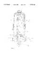
- FIG. 1is an elevational view, partly in section, of an embodiment of the present invention.
- FIG. 2is a sectional view of a second embodiment of the present invention.
- FIG. 3is a sectional view of a third embodiment of the present invention.
- FIG. 4is a sectional view of a fourth embodiment of the present invention.
- the cooling medium filtercomprises a housing 1a encompassing an upper housing member 11a which is cup-shaped and is supported at the open edge thereof by a threaded section and a sealing at a lower housing member 12a.
- the lower housing member 12is provided with an inlet opening 13a and an outlet opening 14a for the cooling medium.
- a check valve 5ais attached in front of the inlet opening 13a and the outlet opening 14a.
- a filter insert 2acomprising two front disks and a folded rim of paper or other suitable materials.
- FIG. 2illustrates the two housing members 11b and 12b in a threadably connected condition wherein a chamber 3b in the interior of the filter insert 2b has already been opened.
- the filter insert 2b at the lower front disk thereofcomprises snap-in means 111b which are engageable with snap-in means 110b at the housing member 11b.
- the snap-in connectionis known in the art.
- the chamber 3bis designed with a jacket serving as a supporting dome 35b for the filter insert 2b.
- the chamber 3bcomprises a lifter 32b beside which a break-off line 34b is provided in the front wall. As illustrated in FIG. 2, the break-off line is already broken by the contact of the lifter 32 when screwing together the two housing members 11b and 12b.
- the chamber 3b also at the upper front side thereofhas been opened wherein a spike 4b having been attached at the upper housing member 12b protruding in axial direction has broken a diaphragm 31b at the upper front side of the chamber 3b.
- coolantwill flow through the chamber 3b in the axial direction.
- FIG. 3illustrates another embodiment of a chamber 3.
- the chamber 3cis designed as a chamber which is closed at all sides thereof and to be inserted into the interior of the filter insert 2c with the jacket of the chamber not serving as a supporting dome.
- the lifter 32cWhen threadably connecting the housing members 11 and 12, the lifter 32c will press against the lower front disk of the filter insert 2c and will open a break-off line positioned beside the projections 36c whereby the lower front wall of the chamber 3c is opened.
- the spike 4cwhich is positioned similar to the embodiment in FIG. 2 will penetrate through a further break-off line or a thin wall area at the lower front side of the chamber 3c and will open the chamber.
- the attachment with snap-in means 110 and 111corresponds with the embodiment in FIG. 2.
- the latterWhen inserting the chamber 3c into the interior of the filter insert 2c, the latter will first be secured with the snap-in means 110c and 111c at the housing member 11c.
- FIG. 4illustrates a further embodiment of the cooling medium filter.
- a cup-shaped housing 1dencompasses a filter insert 2d.
- a chamber 3dis provided with generally cylindrical form.
- a lifter 32dis attached adjacent to a break-off line 34d, and several projections 36d with the height thereof smaller than the height of the lifter 32d.
- a break-off line 31dis provided at the opposite front side of chamber 3d.
- the housing 1comprises a front wall 15d facing a motor housing positioned above in FIG. 4 and not provided with a numeral.
- the front wall 15dcomprises a central opening 16d with an inner thread which may be screwed onto a threaded connection piece 6d in the motor housing which has a corresponding outer thread.
- An outlet opening 14d for the filtered mediumis positioned centrally in the threaded connection piece 6d.
- the front wallprovides several inlet openings 13d through which the medium to be filtered, cooling water or coolant in this case, will enter into the housing 1.
- the corresponding connection lines in the motor housingare not illustrated.
- An annual sealing 17dis attached at the front wall 15d radially outwards of the inlet openings.
- the threaded connection piece 6dsupports a spike 4d at the free end thereof.
- the spike 4dwill break the break-off line 31d, and the lifter 32d opens the break-off line 34d such, that the medium streams through the chamber 3d.
- the housing 1dis sealingly connected with the motor housing by means of the annual sealing 17d.
Landscapes
- Chemical & Material Sciences (AREA)
- Chemical Kinetics & Catalysis (AREA)
- Engineering & Computer Science (AREA)
- Combustion & Propulsion (AREA)
- Mechanical Engineering (AREA)
- General Engineering & Computer Science (AREA)
- Separation Using Semi-Permeable Membranes (AREA)
- Filtration Of Liquid (AREA)
Abstract
Description
Claims (20)
Applications Claiming Priority (2)
| Application Number | Priority Date | Filing Date | Title |
|---|---|---|---|
| DE19540251.0 | 1995-10-28 | ||
| DE19540251ADE19540251C2 (en) | 1995-10-28 | 1995-10-28 | Coolant filter |
Publications (1)
| Publication Number | Publication Date |
|---|---|
| US5753116Atrue US5753116A (en) | 1998-05-19 |
Family
ID=7776072
Family Applications (1)
| Application Number | Title | Priority Date | Filing Date |
|---|---|---|---|
| US08/736,139Expired - LifetimeUS5753116A (en) | 1995-10-28 | 1996-10-28 | Coolant filter |
Country Status (5)
| Country | Link |
|---|---|
| US (1) | US5753116A (en) |
| EP (1) | EP0770416B1 (en) |
| JP (1) | JP4002631B2 (en) |
| BR (1) | BR9605334A (en) |
| DE (1) | DE19540251C2 (en) |
Cited By (42)
| Publication number | Priority date | Publication date | Assignee | Title |
|---|---|---|---|---|
| US6068763A (en)* | 1997-09-12 | 2000-05-30 | Purolator Products Company | Spin-on oil filter with replaceable element |
| US6235194B1 (en)* | 2000-03-08 | 2001-05-22 | Parker-Hannifin Corporation | Recharge and filter assembly with replaceable cartridge |
| AU736775B2 (en)* | 1997-07-18 | 2001-08-02 | Baldwin Filters, Inc. | Coolant filter having a delayed release supplemental coolant additive cartridge |
| EP1287871A1 (en)* | 2001-08-31 | 2003-03-05 | Hydac Filtertechnik GmbH | Filter device |
| US6616838B1 (en)* | 2001-04-20 | 2003-09-09 | Lazarus E. Harris | No-spill oil filter |
| US6835304B2 (en) | 2000-03-08 | 2004-12-28 | The Penray Companies, Inc. | Device for monitoring of a coolant regeneration system |
| US20050194301A1 (en)* | 2004-03-05 | 2005-09-08 | Hacker John R. | Liquid filter assembly for use with treatment agent; and, methods |
| WO2006005329A1 (en)* | 2004-07-14 | 2006-01-19 | Hengst Gmbh & Co. Kg | Oil/coolant module with coolant treatment system |
| WO2006005331A1 (en)* | 2004-07-14 | 2006-01-19 | Hengst Gmbh & Co. Kg | Coolant conditioning unit comprising a non-return valve |
| US20070235378A1 (en)* | 2004-03-05 | 2007-10-11 | Donaldson Corporation Company, Inc. | Top Load Liquid Filter Assembly for Use with Treatment Agent; and, Methods |
| US20090064646A1 (en)* | 2004-08-06 | 2009-03-12 | Donaldson Company, Inc. | Air filter arrangement; assembly; and methods |
| US20090101595A1 (en)* | 2007-10-17 | 2009-04-23 | Caterpillar Inc. | Canister Filter System With Drain That Cooperates With Filter Element |
| US20090127198A1 (en)* | 2007-11-19 | 2009-05-21 | Caterpillar Inc. | Fluid filter system |
| US20090151311A1 (en)* | 2005-01-13 | 2009-06-18 | Donaldson Company, Inc. | Air filter cartridge and air cleaner assembly |
| US7625419B2 (en) | 2006-05-10 | 2009-12-01 | Donaldson Company, Inc. | Air filter arrangement; assembly; and, methods |
| WO2010090576A1 (en)* | 2009-02-05 | 2010-08-12 | Scania Cv Ab | Cooling system for liquid cooling of a combustion engine |
| US20110073537A1 (en)* | 2007-10-17 | 2011-03-31 | Caterpillar, Inc. | Canister Filter System With Drain That Cooperates With Filter Element |
| US20110132828A1 (en)* | 2007-11-19 | 2011-06-09 | Caterpillar, Inc. | Fluid Filter System |
| USD646350S1 (en) | 2010-10-01 | 2011-10-04 | Caterpillar Inc. | Filter |
| USD646750S1 (en) | 2010-10-01 | 2011-10-11 | Caterpillar Inc. | Fuel filter |
| US8034145B2 (en) | 2004-06-14 | 2011-10-11 | Donaldson Company, Inc. | Air filter arrangement; assembly; and, methods |
| US8038878B2 (en) | 2008-11-26 | 2011-10-18 | Mann+Hummel Gmbh | Integrated filter system for a coolant reservoir and method |
| USD648822S1 (en) | 2010-10-01 | 2011-11-15 | Caterpillar Inc. | Fuel filter |
| US8496723B2 (en) | 2005-01-13 | 2013-07-30 | Donaldson Company, Inc. | Air filter arrangement |
| WO2015112421A1 (en)* | 2014-01-24 | 2015-07-30 | Caterpillar Inc. | Filter base system and filter assembly |
| US9320997B2 (en) | 2013-06-28 | 2016-04-26 | Donaldson Company, Inc. | Air filter cartridges; air cleaner assemblies; housings; features; components; and, methods |
| US9555370B2 (en) | 2007-09-07 | 2017-01-31 | Donaldson Company, Inc. | Air filter assembly; components thereof; and, methods |
| US9587532B1 (en)* | 2012-03-22 | 2017-03-07 | Vinh Au | Oil, coolant, and exahust gas circulation system, elements and kits |
| US9623351B2 (en) | 2009-04-09 | 2017-04-18 | Cummins Filtration Ip, Inc. | Filtration sealing system |
| US20190271242A1 (en)* | 2015-08-14 | 2019-09-05 | Kohler Co. | Internal combustion engine and oil treatment apparatus for use with the same |
| US10434454B2 (en) | 2011-06-30 | 2019-10-08 | Donaldson Company, Inc. | Filter cartridge |
| US11020698B2 (en) | 2015-12-11 | 2021-06-01 | Cummins Filtration Ip, Inc. | Filter with variable cross-section axial seal |
| US11110382B2 (en) | 2014-12-27 | 2021-09-07 | Donaldson Company, Inc. | Filter cartridges; air cleaner assemblies; housings; features; components; and, methods |
| US11141687B2 (en) | 2016-05-02 | 2021-10-12 | Cummins Filtration Ip, Inc. | Filter with interlocking housing interface |
| US11167234B2 (en) | 2016-03-18 | 2021-11-09 | Cummins Filtration Ip, Inc. | Interlocked stable filter assembly |
| US11198082B2 (en) | 2017-08-31 | 2021-12-14 | Donaldson Company, Inc. | Filter cartridges; air cleaner assemblies; housings; features; components; and methods |
| US11235275B2 (en) | 2017-03-16 | 2022-02-01 | Cummins Filtration Ip, Inc. | Filtration sealing system |
| US11298640B2 (en) | 2017-01-25 | 2022-04-12 | Cummins Filtration Ip, Inc. | Expandable threaded adaptor for threadless shell |
| US20220134263A1 (en)* | 2019-07-16 | 2022-05-05 | Cummins Filtration Ip, Inc. | Filter cartridge with valve activation feature |
| US11724220B2 (en) | 2017-02-21 | 2023-08-15 | Cummins Filtration Ip, Inc. | Undulated interlocking housing-endplate interface geometry |
| US11772026B2 (en) | 2014-09-15 | 2023-10-03 | Donaldson Company, Inc. | Filter cartridges; air cleaner assemblies; housings; features; components; and, methods |
| US12263428B2 (en) | 2018-07-23 | 2025-04-01 | Cummins Filtration Sarl | Radial seal for spin-on filter |
Families Citing this family (15)
| Publication number | Priority date | Publication date | Assignee | Title |
|---|---|---|---|---|
| US5662799A (en) | 1996-06-21 | 1997-09-02 | Fleetguard, Inc. | Slow release coolant filter |
| GB2368030B (en)* | 1998-02-17 | 2002-07-03 | Cummins Engine Co Inc | A coolant filter assembly |
| US5988265A (en)* | 1998-02-17 | 1999-11-23 | Cummins Engine Company, Inc. | Fuel cooler and coolant filter assembly |
| SE521602C2 (en)* | 1998-07-31 | 2003-11-18 | Volvo Lastvagnar Ab | Device for cooling systems |
| US6264833B1 (en)* | 1998-12-14 | 2001-07-24 | Alliedsignal Inc. | Coolant filter assembly for a vehicle |
| DE29916265U1 (en)* | 1999-09-17 | 2001-02-08 | Ing. Walter Hengst GmbH & Co KG, 48147 Münster | Fluid filter with removable, central component |
| DE10202086B4 (en)* | 2002-01-21 | 2005-12-08 | Webasto Ag | Coolant pump |
| DE202004008252U1 (en)* | 2004-05-19 | 2005-09-29 | Hengst Gmbh & Co.Kg | Filter, in particular, for cooling water of an internal combustion engine comprises an additive container which incorporates a mechanism closing the container when the filter insert is removed from its housing |
| DE102005021957B4 (en)* | 2004-05-19 | 2007-03-22 | Hengst Gmbh & Co.Kg | Filter, in particular cooling water filter of an internal combustion engine |
| DE102004049877B4 (en)* | 2004-10-13 | 2008-03-27 | Brita Gmbh | Filter cartridge and seat element for a filter cartridge |
| DE202005007936U1 (en)* | 2005-05-17 | 2006-09-28 | Hengst Gmbh & Co.Kg | Coolant filter for internal combustion engine, has maintenance insert with renewable coolant maintenance accessory in interior of filter, and silicate as preservative for coolant, where preservative arranged separately from accessory |
| DE202006010857U1 (en)* | 2006-07-12 | 2007-11-15 | Mann + Hummel Gmbh | filter element |
| JPWO2009069402A1 (en)* | 2007-11-29 | 2011-04-07 | インテグリス・インコーポレーテッド | Filter unit and filter cartridge |
| CH707499B1 (en)* | 2013-01-19 | 2017-02-28 | Schwanden Kunststoff | Compensation tank for the cooling system of an internal combustion engine. |
| CN112648759A (en)* | 2020-12-31 | 2021-04-13 | 博拓(苏州)新能源技术有限公司 | Double-working-condition air source heat pump circulating system |
Citations (11)
| Publication number | Priority date | Publication date | Assignee | Title |
|---|---|---|---|---|
| GB590618A (en)* | 1944-12-13 | 1947-07-23 | Thomas Claud Worth | Improvements in and relating to oil filters |
| US3710930A (en)* | 1970-12-21 | 1973-01-16 | M Owdom | Filter package |
| US3749247A (en)* | 1970-09-21 | 1973-07-31 | Phillips Petroleum Co | Addition of oxidation inhibitor to lubricating oil |
| US3912633A (en)* | 1974-09-09 | 1975-10-14 | Arthur Delaney | Oil filter with pull tab drain |
| US4151823A (en)* | 1977-07-28 | 1979-05-01 | Grosse Leland J | Quick-change oil filter/reservoir system for internal combustion engine |
| US4265748A (en)* | 1980-01-11 | 1981-05-05 | Tecnocar S P A | Lubricant filter for internal combustion engines |
| US5030345A (en)* | 1988-07-07 | 1991-07-09 | Thomas Albert E | Non-drip and full prime filter |
| US5050549A (en)* | 1990-06-14 | 1991-09-24 | Sturmon George R | Method of cleaning internal combustion engine cooling system and filter for use therein |
| US5435462A (en)* | 1993-01-20 | 1995-07-25 | Nordson Corporation | Liquid cartridge storage case for use with liquid dipenser |
| US5552040A (en)* | 1992-09-24 | 1996-09-03 | Sundstrand Corporation | Method of increasing service life of oil and a filter for use therewith |
| US5591330A (en)* | 1994-05-25 | 1997-01-07 | T/F Purifiner, Inc. | Oil filter containing an oil soluble thermoplastic additive material therein |
Family Cites Families (7)
| Publication number | Priority date | Publication date | Assignee | Title |
|---|---|---|---|---|
| US4075097A (en)* | 1975-04-01 | 1978-02-21 | Monroe Auto Equipment Company | Oil filter with oil improving dissolving body |
| US4259184A (en)* | 1976-08-30 | 1981-03-31 | Arnal Hubert A D | Sealed container adapted for medical usage and method of sealing |
| DE3712284A1 (en)* | 1987-04-10 | 1988-10-27 | Leifheit Ag | DEVICE FOR IMPROVING THE QUALITY OF DRINKING WATER |
| FR2673120B1 (en)* | 1991-02-27 | 1993-12-31 | Fleetguard | REUSABLE FILTER FOR FLUID HAVING A FILTERING FUNCTION AND AN ADDITIVE FEEDING FUNCTION. |
| DE4310492A1 (en)* | 1993-03-31 | 1994-10-06 | Hydac Filtertechnik Gmbh | Filter device with key port connection |
| US5435346A (en)* | 1994-02-14 | 1995-07-25 | Alliedsignal Inc. | Device for treating and conditioning engine coolant |
| DE4424552C2 (en)* | 1994-07-12 | 1996-07-04 | Votech Filter Gmbh | Filter cartridge for separating particles with a retention device |
- 1995
- 1995-10-28DEDE19540251Apatent/DE19540251C2/ennot_activeExpired - Fee Related
- 1996
- 1996-09-18EPEP96114928Apatent/EP0770416B1/ennot_activeExpired - Lifetime
- 1996-10-25JPJP28376896Apatent/JP4002631B2/ennot_activeExpired - Fee Related
- 1996-10-28USUS08/736,139patent/US5753116A/ennot_activeExpired - Lifetime
- 1996-10-29BRBR9605334Apatent/BR9605334A/ennot_activeIP Right Cessation
Patent Citations (11)
| Publication number | Priority date | Publication date | Assignee | Title |
|---|---|---|---|---|
| GB590618A (en)* | 1944-12-13 | 1947-07-23 | Thomas Claud Worth | Improvements in and relating to oil filters |
| US3749247A (en)* | 1970-09-21 | 1973-07-31 | Phillips Petroleum Co | Addition of oxidation inhibitor to lubricating oil |
| US3710930A (en)* | 1970-12-21 | 1973-01-16 | M Owdom | Filter package |
| US3912633A (en)* | 1974-09-09 | 1975-10-14 | Arthur Delaney | Oil filter with pull tab drain |
| US4151823A (en)* | 1977-07-28 | 1979-05-01 | Grosse Leland J | Quick-change oil filter/reservoir system for internal combustion engine |
| US4265748A (en)* | 1980-01-11 | 1981-05-05 | Tecnocar S P A | Lubricant filter for internal combustion engines |
| US5030345A (en)* | 1988-07-07 | 1991-07-09 | Thomas Albert E | Non-drip and full prime filter |
| US5050549A (en)* | 1990-06-14 | 1991-09-24 | Sturmon George R | Method of cleaning internal combustion engine cooling system and filter for use therein |
| US5552040A (en)* | 1992-09-24 | 1996-09-03 | Sundstrand Corporation | Method of increasing service life of oil and a filter for use therewith |
| US5435462A (en)* | 1993-01-20 | 1995-07-25 | Nordson Corporation | Liquid cartridge storage case for use with liquid dipenser |
| US5591330A (en)* | 1994-05-25 | 1997-01-07 | T/F Purifiner, Inc. | Oil filter containing an oil soluble thermoplastic additive material therein |
Cited By (110)
| Publication number | Priority date | Publication date | Assignee | Title |
|---|---|---|---|---|
| AU736775B2 (en)* | 1997-07-18 | 2001-08-02 | Baldwin Filters, Inc. | Coolant filter having a delayed release supplemental coolant additive cartridge |
| US6068763A (en)* | 1997-09-12 | 2000-05-30 | Purolator Products Company | Spin-on oil filter with replaceable element |
| US6235194B1 (en)* | 2000-03-08 | 2001-05-22 | Parker-Hannifin Corporation | Recharge and filter assembly with replaceable cartridge |
| US6475379B2 (en)* | 2000-03-08 | 2002-11-05 | Parker-Hannifin Corporation | Recharge and filter cartridge |
| US6835304B2 (en) | 2000-03-08 | 2004-12-28 | The Penray Companies, Inc. | Device for monitoring of a coolant regeneration system |
| US6616838B1 (en)* | 2001-04-20 | 2003-09-09 | Lazarus E. Harris | No-spill oil filter |
| EP1287871A1 (en)* | 2001-08-31 | 2003-03-05 | Hydac Filtertechnik GmbH | Filter device |
| US7238285B2 (en) | 2004-03-05 | 2007-07-03 | Donaldson Company, Inc. | Liquid filter assembly for use with treatment agent; and, methods |
| US20070235378A1 (en)* | 2004-03-05 | 2007-10-11 | Donaldson Corporation Company, Inc. | Top Load Liquid Filter Assembly for Use with Treatment Agent; and, Methods |
| US20050194301A1 (en)* | 2004-03-05 | 2005-09-08 | Hacker John R. | Liquid filter assembly for use with treatment agent; and, methods |
| US20060065584A1 (en)* | 2004-03-05 | 2006-03-30 | Donaldson Company, Inc. | Liquid filter assembly for use with treatment agent and methods |
| US7160451B2 (en) | 2004-03-05 | 2007-01-09 | Donaldson Company, Inc. | Liquid filter assembly for use with treatment agent and methods |
| US9937455B2 (en) | 2004-06-14 | 2018-04-10 | Donaldson Company, Inc. | Air filter arrangement; assembly; and, methods |
| US8034145B2 (en) | 2004-06-14 | 2011-10-11 | Donaldson Company, Inc. | Air filter arrangement; assembly; and, methods |
| US10603618B2 (en) | 2004-06-14 | 2020-03-31 | Donaldson Company, Inc. | Air filter arrangement; assembly; and, methods |
| US11291943B2 (en) | 2004-06-14 | 2022-04-05 | Donaldson Company, Inc. | Air filter arrangement; assembly; and, methods |
| US9120047B2 (en) | 2004-06-14 | 2015-09-01 | Donaldson Company, Inc. | Air filter arrangement; assembly; and, methods |
| US8480779B2 (en)* | 2004-06-14 | 2013-07-09 | Donaldson Company, Inc. | Air filter arrangement; assembly; and, methods |
| US20080006229A1 (en)* | 2004-07-14 | 2008-01-10 | Hengst Gmbh & Co. Kg | Oil/Coolant Module with Coolant Treatment System |
| US20080190832A1 (en)* | 2004-07-14 | 2008-08-14 | Hengst Gmbh & Co. Kg | Coolant Conditioning Unit Comprising A Non-Return Valve |
| WO2006005329A1 (en)* | 2004-07-14 | 2006-01-19 | Hengst Gmbh & Co. Kg | Oil/coolant module with coolant treatment system |
| CN100554661C (en)* | 2004-07-14 | 2009-10-28 | 亨格斯特有限及两合公司 | Oil/coolant module with coolant servicing system |
| US8783216B2 (en)* | 2004-07-14 | 2014-07-22 | Hengst Gmbh & Co. Kg | Oil/coolant module with coolant treatment system |
| US8691090B2 (en)* | 2004-07-14 | 2014-04-08 | Hengst Gmbh & Co. Kg. | Coolant conditioning unit comprising a non-return valve |
| WO2006005331A1 (en)* | 2004-07-14 | 2006-01-19 | Hengst Gmbh & Co. Kg | Coolant conditioning unit comprising a non-return valve |
| US11759744B2 (en) | 2004-08-06 | 2023-09-19 | Donaldson Company, Inc. | Air filter arrangement; assembly; and, methods |
| US8277532B2 (en) | 2004-08-06 | 2012-10-02 | Donaldson Company, Inc. | Air filter arrangement; assembly; and methods |
| US11207632B2 (en) | 2004-08-06 | 2021-12-28 | Donaldson Company, Inc. | Air filter arrangement; assembly; and, methods |
| US8906128B2 (en) | 2004-08-06 | 2014-12-09 | Donaldson Company, Inc. | Air filter arrangement; assembly; and, methods |
| US9795911B2 (en) | 2004-08-06 | 2017-10-24 | Donaldson Company, Inc. | Air filter arrangement; assembly; and, methods |
| US20090064646A1 (en)* | 2004-08-06 | 2009-03-12 | Donaldson Company, Inc. | Air filter arrangement; assembly; and methods |
| US10556201B2 (en) | 2004-08-06 | 2020-02-11 | Donaldson Company, Inc. | Air filter arrangement; assembly; and, methods |
| US10065145B2 (en) | 2005-01-13 | 2018-09-04 | Donaldson Company, Inc. | Air filter arrangement; assembly; and, methods |
| US8709119B2 (en) | 2005-01-13 | 2014-04-29 | Donaldson Company, Inc. | Air filter cartridge and air cleaner assembly |
| US8292983B2 (en) | 2005-01-13 | 2012-10-23 | Donaldson Company, Inc. | Air filter cartridge and air cleaner assembly |
| US20090151311A1 (en)* | 2005-01-13 | 2009-06-18 | Donaldson Company, Inc. | Air filter cartridge and air cleaner assembly |
| US10421034B2 (en) | 2005-01-13 | 2019-09-24 | Donaldson Company, Inc. | Air filter arrangement; assembly; and, methods |
| US12070711B2 (en) | 2005-01-13 | 2024-08-27 | Donaldson Company, Inc. | Air filter arrangement; assembly; and, methods |
| US11826689B2 (en) | 2005-01-13 | 2023-11-28 | Donaldson Company, Inc. | Air filter arrangement; assembly; and, methods |
| US8496723B2 (en) | 2005-01-13 | 2013-07-30 | Donaldson Company, Inc. | Air filter arrangement |
| US10864475B2 (en) | 2005-01-13 | 2020-12-15 | Donaldson Company, Inc. | Air filter arrangement; assembly; and, methods |
| US11020699B2 (en) | 2005-01-13 | 2021-06-01 | Donaldson Company, Inc. | Air filter arrangement; assembly; and, methods |
| US11951429B2 (en) | 2005-01-13 | 2024-04-09 | Donaldson Company, Inc. | Air filter arrangement; assembly; and, methods |
| US8636820B2 (en) | 2005-01-13 | 2014-01-28 | Donaldson Company, Inc. | Air filter arrangement |
| US12138574B2 (en) | 2005-01-13 | 2024-11-12 | Donaldson Company, Inc. | Air Filter Arrangement; Assembly; and, Methods |
| US9180399B2 (en) | 2005-01-13 | 2015-11-10 | Donaldson Company, Inc. | Air filter arrangement |
| US9527023B2 (en) | 2005-01-13 | 2016-12-27 | Donaldson Comapny, Inc. | Air filter arrangement; assembly; and, methods |
| US10315144B2 (en) | 2005-01-13 | 2019-06-11 | Donaldson Company, Inc. | Air filter arrangement; assembly; and, methods |
| US7625419B2 (en) | 2006-05-10 | 2009-12-01 | Donaldson Company, Inc. | Air filter arrangement; assembly; and, methods |
| US8062399B2 (en) | 2006-05-10 | 2011-11-22 | Donaldson Company, Inc. | Air filter arrangement; assembly; and, methods |
| US8328897B2 (en) | 2006-05-10 | 2012-12-11 | Donaldson Company, Inc. | Air cleaner arrangement; assembly; and, methods |
| US9555370B2 (en) | 2007-09-07 | 2017-01-31 | Donaldson Company, Inc. | Air filter assembly; components thereof; and, methods |
| US10422306B2 (en) | 2007-09-07 | 2019-09-24 | Donaldson Company, Inc. | Air filter assembly; components thereof; and, methods |
| US8460545B2 (en) | 2007-10-17 | 2013-06-11 | Caterpillar Inc. | Canister filter system with drain that cooperates with filter element |
| US9511314B2 (en) | 2007-10-17 | 2016-12-06 | Caterpillar Inc. | Canister filter system with drain that cooperates with filter element |
| US8535529B2 (en) | 2007-10-17 | 2013-09-17 | Caterpillar Inc. | Canister filter system with drain that cooperates with filter element |
| US8501003B2 (en) | 2007-10-17 | 2013-08-06 | Caterpillar Inc. | Canister filter system with drain that cooperates with filter element |
| US20090101595A1 (en)* | 2007-10-17 | 2009-04-23 | Caterpillar Inc. | Canister Filter System With Drain That Cooperates With Filter Element |
| US20110073537A1 (en)* | 2007-10-17 | 2011-03-31 | Caterpillar, Inc. | Canister Filter System With Drain That Cooperates With Filter Element |
| US8157997B2 (en) | 2007-10-17 | 2012-04-17 | Caterpillar Inc. | Canister filter system with drain that cooperates with filter element |
| US9089795B2 (en) | 2007-11-19 | 2015-07-28 | Caterpillar Inc. | Fluid filter system |
| US8540080B2 (en) | 2007-11-19 | 2013-09-24 | Caterpillar Inc. | Fluid filter system |
| US20090127198A1 (en)* | 2007-11-19 | 2009-05-21 | Caterpillar Inc. | Fluid filter system |
| US8419938B2 (en) | 2007-11-19 | 2013-04-16 | Catepillar Inc. | Fluid filter system |
| US8272516B2 (en) | 2007-11-19 | 2012-09-25 | Caterpillar Inc. | Fluid filter system |
| US20110132828A1 (en)* | 2007-11-19 | 2011-06-09 | Caterpillar, Inc. | Fluid Filter System |
| US8038878B2 (en) | 2008-11-26 | 2011-10-18 | Mann+Hummel Gmbh | Integrated filter system for a coolant reservoir and method |
| WO2010090576A1 (en)* | 2009-02-05 | 2010-08-12 | Scania Cv Ab | Cooling system for liquid cooling of a combustion engine |
| US11833459B2 (en) | 2009-04-09 | 2023-12-05 | Cummins Filtration Ip, Inc. | Filtration sealing system |
| US9782708B2 (en) | 2009-04-09 | 2017-10-10 | Cummins Filtration Ip, Inc. | Filtration sealing system |
| US9623351B2 (en) | 2009-04-09 | 2017-04-18 | Cummins Filtration Ip, Inc. | Filtration sealing system |
| US10112138B2 (en) | 2009-04-09 | 2018-10-30 | Cummins Filtration Ip, Inc. | Filtration sealing system |
| USD648822S1 (en) | 2010-10-01 | 2011-11-15 | Caterpillar Inc. | Fuel filter |
| USD646350S1 (en) | 2010-10-01 | 2011-10-04 | Caterpillar Inc. | Filter |
| USD646750S1 (en) | 2010-10-01 | 2011-10-11 | Caterpillar Inc. | Fuel filter |
| US10434454B2 (en) | 2011-06-30 | 2019-10-08 | Donaldson Company, Inc. | Filter cartridge |
| US9587532B1 (en)* | 2012-03-22 | 2017-03-07 | Vinh Au | Oil, coolant, and exahust gas circulation system, elements and kits |
| US12186694B2 (en) | 2013-06-28 | 2025-01-07 | Donaldson Company, Inc. | Filter cartridges; air cleaner assemblies; housings; features; components; and, methods |
| US10610816B2 (en) | 2013-06-28 | 2020-04-07 | Donaldson Company, Inc. | Filter cartridges; air cleaner assemblies; housings; features; components; and, methods |
| US12115484B2 (en) | 2013-06-28 | 2024-10-15 | Donaldson Company, Inc. | Filter cartridges; air cleaner assemblies; housings; features; components; and, methods |
| US11752460B2 (en) | 2013-06-28 | 2023-09-12 | Donaldson Company, Inc. | Filter cartridges; air cleaner assemblies; housings; features; components; and, methods |
| US9320997B2 (en) | 2013-06-28 | 2016-04-26 | Donaldson Company, Inc. | Air filter cartridges; air cleaner assemblies; housings; features; components; and, methods |
| US11298643B2 (en) | 2013-06-28 | 2022-04-12 | Donaldson Company, Inc. | Filter cartridges; air cleaner assemblies; housings; features; components; and, methods |
| US10046260B2 (en) | 2013-06-28 | 2018-08-14 | Donaldson Company, Inc. | Air filter cartridges; air cleaner assemblies; housings; features; components; and, methods |
| US9446334B2 (en) | 2014-01-24 | 2016-09-20 | Caterpillar Inc. | Filter base system and filter assembly |
| WO2015112421A1 (en)* | 2014-01-24 | 2015-07-30 | Caterpillar Inc. | Filter base system and filter assembly |
| US12145093B2 (en) | 2014-09-15 | 2024-11-19 | Donaldson Company, Inc. | Filter cartridges; air cleaner assemblies; housings; features; components; and, methods |
| US11772026B2 (en) | 2014-09-15 | 2023-10-03 | Donaldson Company, Inc. | Filter cartridges; air cleaner assemblies; housings; features; components; and, methods |
| US11110382B2 (en) | 2014-12-27 | 2021-09-07 | Donaldson Company, Inc. | Filter cartridges; air cleaner assemblies; housings; features; components; and, methods |
| US12168194B2 (en) | 2014-12-27 | 2024-12-17 | Donaldson Company, Inc. | Filter cartridges; air cleaner assemblies; housings; features; components; and, methods |
| US11808182B2 (en) | 2015-08-14 | 2023-11-07 | Kohler Co. | Internal combustion engine and oil treatment apparatus for use with the same |
| US11499452B2 (en) | 2015-08-14 | 2022-11-15 | Kohler Co. | Internal combustion engine and oil treatment apparatus for use with the same |
| US10858971B2 (en)* | 2015-08-14 | 2020-12-08 | Kohler Co. | Internal combustion engine and oil treatment apparatus for use with the same |
| US20190271242A1 (en)* | 2015-08-14 | 2019-09-05 | Kohler Co. | Internal combustion engine and oil treatment apparatus for use with the same |
| US11020698B2 (en) | 2015-12-11 | 2021-06-01 | Cummins Filtration Ip, Inc. | Filter with variable cross-section axial seal |
| US11167234B2 (en) | 2016-03-18 | 2021-11-09 | Cummins Filtration Ip, Inc. | Interlocked stable filter assembly |
| US11813559B2 (en) | 2016-03-18 | 2023-11-14 | Cummins Filtration Ip, Inc. | Interlocked stable filter assembly |
| US11660560B2 (en) | 2016-05-02 | 2023-05-30 | Cummins Filtration Ip, Inc. | Filter with interlocking housing interface |
| US11141687B2 (en) | 2016-05-02 | 2021-10-12 | Cummins Filtration Ip, Inc. | Filter with interlocking housing interface |
| US11298640B2 (en) | 2017-01-25 | 2022-04-12 | Cummins Filtration Ip, Inc. | Expandable threaded adaptor for threadless shell |
| US11724220B2 (en) | 2017-02-21 | 2023-08-15 | Cummins Filtration Ip, Inc. | Undulated interlocking housing-endplate interface geometry |
| US12330099B2 (en) | 2017-02-21 | 2025-06-17 | Cummins Filtration Ip, Inc. | Undulated interlocking housing-endplate interface geometry |
| US11235275B2 (en) | 2017-03-16 | 2022-02-01 | Cummins Filtration Ip, Inc. | Filtration sealing system |
| US12036499B2 (en) | 2017-08-31 | 2024-07-16 | Donaldson Company, Inc | Filter cartridges; air cleaner assemblies; housings; features; components; and, methods |
| US11801466B2 (en) | 2017-08-31 | 2023-10-31 | Donaldson Company, Inc. | Filter cartridges; air cleaner assemblies; housings; features; components; and, methods |
| US11198082B2 (en) | 2017-08-31 | 2021-12-14 | Donaldson Company, Inc. | Filter cartridges; air cleaner assemblies; housings; features; components; and methods |
| US12357934B2 (en) | 2017-08-31 | 2025-07-15 | Donaldson Company, Inc. | Filter cartridges; air cleaner assemblies; housings; features; components; and, methods |
| US12263428B2 (en) | 2018-07-23 | 2025-04-01 | Cummins Filtration Sarl | Radial seal for spin-on filter |
| US20220134263A1 (en)* | 2019-07-16 | 2022-05-05 | Cummins Filtration Ip, Inc. | Filter cartridge with valve activation feature |
| US12233359B2 (en)* | 2019-07-16 | 2025-02-25 | Cummins Filtration Ip, Inc. | Filter cartridge with valve activation feature |
Also Published As
| Publication number | Publication date |
|---|---|
| BR9605334A (en) | 1998-07-28 |
| DE19540251A1 (en) | 1997-04-30 |
| JPH09168706A (en) | 1997-06-30 |
| EP0770416B1 (en) | 2001-11-21 |
| DE19540251C2 (en) | 1997-11-20 |
| EP0770416A1 (en) | 1997-05-02 |
| JP4002631B2 (en) | 2007-11-07 |
Similar Documents
| Publication | Publication Date | Title |
|---|---|---|
| US5753116A (en) | Coolant filter | |
| EP2234689B1 (en) | Fluid filter system | |
| US5567309A (en) | Self-filtration cap | |
| US4357240A (en) | Disposable, one-piece filter unit | |
| JP3373597B2 (en) | Fuel filter with internal vent | |
| US9248393B2 (en) | Cup-shaped housing, device for separating liquid from air, and method for mounting the cup-shaped housing on a nipple | |
| US5104533A (en) | Filtration unit with pressure compensation | |
| JPH0731811A (en) | Oil filter cartridge | |
| JPH01189308A (en) | Fluid filtering apparatus | |
| CA2136148A1 (en) | Liquid separation apparatus and method | |
| US4702790A (en) | Fuel filter apparatus and the method of manufacture | |
| US20220233988A1 (en) | Separating Apparatus for Separating Liquid from Gas, in Particular Air, and Separating System of a Machine | |
| JPH0244567B2 (en) | ||
| JPS62501274A (en) | Filter unit and filtration device including the same | |
| US5514275A (en) | Smooth wall filter vessel and liner | |
| US3300049A (en) | Oil filter adapter kit | |
| US10143950B2 (en) | Filter for fluids and an additive container for a filter | |
| JPS638528Y2 (en) | ||
| JP4098123B2 (en) | Purification cartridge | |
| JPH08303322A (en) | Fuel injection pipe introduction device | |
| US6319415B1 (en) | Method and apparatus for axial flow filtration | |
| RU2057579C1 (en) | Apparatus for liquid saturation with gas | |
| JP2616354B2 (en) | Dialysis machine dialysis container | |
| WO1988002663A1 (en) | Centrifugal separator | |
| KR20030013339A (en) | A fuel filter for diesel fuel |
Legal Events
| Date | Code | Title | Description |
|---|---|---|---|
| AS | Assignment | Owner name:ING. WALTER HENGST GMBH & CO. KG, GERMANY Free format text:ASSIGNMENT OF ASSIGNORS INTEREST;ASSIGNORS:BAUMANN, DIETER;BATRAM, BERNHARD;HOMBERGER, JORG;REEL/FRAME:008322/0385;SIGNING DATES FROM 19961111 TO 19961118 | |
| STCF | Information on status: patent grant | Free format text:PATENTED CASE | |
| AS | Assignment | Owner name:DAIMLER-BENZ AKTIENGESELLSCHAFT, GERMANY Free format text:MERGER RE-RECORD TO CORRECT THE NUMBER OF MICROFILM PAGES FROM 60 TO 98 AT REEL 9360, FRAME 0937.;ASSIGNOR:MERCEDES-BENZ AG;REEL/FRAME:009827/0145 Effective date:19970605 Owner name:DAIMLER-BENZ AKTIENGESELLSCHAFT, GERMANY Free format text:MERGER;ASSIGNOR:MERCEDES-BENZ AG;REEL/FRAME:009360/0937 Effective date:19970605 | |
| AS | Assignment | Owner name:DAIMLERCHRYSLER AG, GERMANY Free format text:MERGER;ASSIGNOR:DAIMLER-BENZ AKTIENGESELLSCHAFT;REEL/FRAME:010133/0556 Effective date:19990108 | |
| AS | Assignment | Owner name:ING. WALTER HENGST GMBH & CO. KG, GERMANY Free format text:ASSIGNMENT OF ASSIGNORS INTEREST;ASSIGNOR:DAIMLER CHRYSLER AG;REEL/FRAME:011887/0910 Effective date:20010515 | |
| FPAY | Fee payment | Year of fee payment:4 | |
| FEPP | Fee payment procedure | Free format text:PAYOR NUMBER ASSIGNED (ORIGINAL EVENT CODE: ASPN); ENTITY STATUS OF PATENT OWNER: LARGE ENTITY | |
| REMI | Maintenance fee reminder mailed | ||
| FPAY | Fee payment | Year of fee payment:8 | |
| FPAY | Fee payment | Year of fee payment:12 |