US5752957A - Polyaxial mechanism for use with orthopaedic implant devices - Google Patents
Polyaxial mechanism for use with orthopaedic implant devicesDownload PDFInfo
- Publication number
- US5752957A US5752957AUS08/799,721US79972197AUS5752957AUS 5752957 AUS5752957 AUS 5752957AUS 79972197 AUS79972197 AUS 79972197AUS 5752957 AUS5752957 AUS 5752957A
- Authority
- US
- United States
- Prior art keywords
- post
- recess
- head
- lower portion
- curvate
- Prior art date
- Legal status (The legal status is an assumption and is not a legal conclusion. Google has not performed a legal analysis and makes no representation as to the accuracy of the status listed.)
- Expired - Lifetime
Links
- 239000007943implantSubstances0.000titleclaimsabstractdescription9
- 230000007246mechanismEffects0.000titledescription4
- 210000004243sweatAnatomy0.000claimsabstractdescription10
- 210000000988bone and boneAnatomy0.000claimsdescription20
- 230000008878couplingEffects0.000claimsdescription12
- 238000010168coupling processMethods0.000claimsdescription12
- 238000005859coupling reactionMethods0.000claimsdescription12
- 230000000087stabilizing effectEffects0.000claimsdescription3
- 238000000034methodMethods0.000abstractdescription7
- 230000008569processEffects0.000abstractdescription5
- 238000003780insertionMethods0.000abstractdescription4
- 230000037431insertionEffects0.000abstractdescription4
- 230000008602contractionEffects0.000abstractdescription2
- 230000000399orthopedic effectEffects0.000abstract1
- 230000000712assemblyEffects0.000description5
- 238000000429assemblyMethods0.000description5
- 238000002513implantationMethods0.000description4
- 210000000115thoracic cavityAnatomy0.000description3
- 230000004323axial lengthEffects0.000description2
- 230000006835compressionEffects0.000description2
- 238000007906compressionMethods0.000description2
- 238000011067equilibrationMethods0.000description2
- 230000007774longtermEffects0.000description2
- 239000002184metalSubstances0.000description2
- 210000000653nervous systemAnatomy0.000description2
- 206010028980NeoplasmDiseases0.000description1
- 210000000845cartilageAnatomy0.000description1
- 230000037326chronic stressEffects0.000description1
- 210000002808connective tissueAnatomy0.000description1
- 201000010099diseaseDiseases0.000description1
- 208000037265diseases, disorders, signs and symptomsDiseases0.000description1
- 230000002068genetic effectEffects0.000description1
- 208000014674injuryDiseases0.000description1
- 210000004705lumbosacral regionAnatomy0.000description1
- 238000012986modificationMethods0.000description1
- 230000004048modificationEffects0.000description1
- 230000007170pathologyEffects0.000description1
- 210000000578peripheral nerveAnatomy0.000description1
- 230000009467reductionEffects0.000description1
- 238000009877renderingMethods0.000description1
- 210000003625skullAnatomy0.000description1
- 125000006850spacer groupChemical group0.000description1
- 210000000278spinal cordAnatomy0.000description1
- 238000001356surgical procedureMethods0.000description1
- 230000008733traumaEffects0.000description1
- 210000002517zygapophyseal jointAnatomy0.000description1
Images


Classifications
- A—HUMAN NECESSITIES
- A61—MEDICAL OR VETERINARY SCIENCE; HYGIENE
- A61B—DIAGNOSIS; SURGERY; IDENTIFICATION
- A61B17/00—Surgical instruments, devices or methods
- A61B17/56—Surgical instruments or methods for treatment of bones or joints; Devices specially adapted therefor
- A61B17/58—Surgical instruments or methods for treatment of bones or joints; Devices specially adapted therefor for osteosynthesis, e.g. bone plates, screws or setting implements
- A61B17/68—Internal fixation devices, including fasteners and spinal fixators, even if a part thereof projects from the skin
- A61B17/70—Spinal positioners or stabilisers, e.g. stabilisers comprising fluid filler in an implant
- A61B17/7001—Screws or hooks combined with longitudinal elements which do not contact vertebrae
- A61B17/7035—Screws or hooks, wherein a rod-clamping part and a bone-anchoring part can pivot relative to each other
- A61B17/7037—Screws or hooks, wherein a rod-clamping part and a bone-anchoring part can pivot relative to each other wherein pivoting is blocked when the rod is clamped
- A—HUMAN NECESSITIES
- A61—MEDICAL OR VETERINARY SCIENCE; HYGIENE
- A61B—DIAGNOSIS; SURGERY; IDENTIFICATION
- A61B17/00—Surgical instruments, devices or methods
- A61B17/56—Surgical instruments or methods for treatment of bones or joints; Devices specially adapted therefor
- A61B17/58—Surgical instruments or methods for treatment of bones or joints; Devices specially adapted therefor for osteosynthesis, e.g. bone plates, screws or setting implements
- A61B17/68—Internal fixation devices, including fasteners and spinal fixators, even if a part thereof projects from the skin
- A61B17/70—Spinal positioners or stabilisers, e.g. stabilisers comprising fluid filler in an implant
- A61B17/7001—Screws or hooks combined with longitudinal elements which do not contact vertebrae
- A61B17/7035—Screws or hooks, wherein a rod-clamping part and a bone-anchoring part can pivot relative to each other
- A61B17/7038—Screws or hooks, wherein a rod-clamping part and a bone-anchoring part can pivot relative to each other to a different extent in different directions, e.g. within one plane only
- A—HUMAN NECESSITIES
- A61—MEDICAL OR VETERINARY SCIENCE; HYGIENE
- A61B—DIAGNOSIS; SURGERY; IDENTIFICATION
- A61B17/00—Surgical instruments, devices or methods
- A61B17/56—Surgical instruments or methods for treatment of bones or joints; Devices specially adapted therefor
- A61B17/58—Surgical instruments or methods for treatment of bones or joints; Devices specially adapted therefor for osteosynthesis, e.g. bone plates, screws or setting implements
- A61B17/68—Internal fixation devices, including fasteners and spinal fixators, even if a part thereof projects from the skin
- A61B17/70—Spinal positioners or stabilisers, e.g. stabilisers comprising fluid filler in an implant
- A61B17/7001—Screws or hooks combined with longitudinal elements which do not contact vertebrae
- A61B17/7032—Screws or hooks with U-shaped head or back through which longitudinal rods pass
Definitions
- This inventionrelates generally to a polyaxial mechanism for use with orthopaedic devices, and more particularly to a polyaxial coupling mechanism connecting the top rod coupling portion of an orthopaedic implant device, for example a spinal screw or hook, to the base thereof.
- the bones and connective tissue of an adult human spinal columnconsists of more than 20 discrete bones coupled sequentially to one another by a tri-joint complex which consist of an anterior disc and the two posterior facet joints, the anterior discs of adjacent bones being cushioned by cartilage spacers referred to as intervertebral discs.
- These more than 20 bonesare anatomically categorized as being members of one of four classifications: cervical, thoracic, lumbar, or sacral.
- the cervical portion of the spinewhich comprises the top of the spine, up to the base of the skull, includes the first 7 vertebrae.
- the intermediate 12 bonesare the thoracic vertebrae, and connect to the lower spine comprising the 5 lumbar vertebrae.
- the base of the spineis the sacral bones (including the coccyx).
- the component bones of the cervical spineare generally smaller than those of the thoracic and lumbar spine. For the purposes of this disclosure, however, the word spine shall refer only to the cervical region.
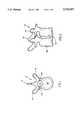
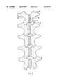
- FIGS. 1, 2, and 3top, side, and posterior views of a vertebral body, a pair1of adjacent vertebral bodies, and a sequence of vertebral bodies are shown, respectively.
- the spinal cordis housed in the central canal 10, protected from the posterior side by a shell of bone called the lamina 12.
- the lamina 12includes a rearwardly and downwardly extending portion called the spinous process 16, and laterally extending structures which are referred to as the transverse processes 14.
- the anterior portion of the spinecomprises a set of generally cylindrically shaped bones which are stacked one on top of the other. These portions of the vertebrae are referred to as the vertebral bodies 20, and are each separated from the other by the intervertebral discs 22.
- the pedicles 24comprise bone bridges which couple the anterior vertebral body 20 to the corresponding lamina 12.
- the spinal column of bonesis highly complex in that it includes over twenty bones coupled to one another, housing and protecting critical elements of the nervous system having innumerable peripheral nerves and circulatory bodies in close proximity.
- the spineis a highly flexible structure, capable of a high degree of curvature and twist in nearly every direction. Genetic or developmental irregularities, trauma, chronic stress, tumors, and disease, however, can result in spinal pathologies which either limit this range of motion, or which threaten the critical elements of the nervous system housed within the spinal column.
- a variety of systemshave been disclosed in the art which achieve this immobilization by implanting artificial assemblies in or on the spinal column. These assemblies may be classified as anterior, posterior, or lateral implants.
- Posterior implantsgenerally comprise pairs of rods, which are aligned along the axis which the bones are to be disposed, and which are then attached to the spinal column by either hooks which couple to the lamina or attach to the transverse processes, or by screws which are inserted through the pedicles.
- “Rod assemblies”generally comprise a plurality of such screws which are implanted through the posterior lateral surfaces of the laminae, through the pedicles, and into their respective vertebral bodies, or hooks which hook to the laminae.
- the screws and hooksare each provided with upper portions which comprise coupling elements, for receiving and securing an elongate rod therethrough.
- the rodextends along the axis of the spine, coupling to the plurality of screws and/or hooks via their coupling elements.
- the rigidity of the rodmay be utilized to align the spine in conformance with a more desired shape.
- the present inventionis a polyaxial rod coupling mechanism having a base member, a post member, a rod receiving member, and a top locking nut.
- a locking pinor dowel
- the base portionmay be either a screw or a hook (or any bone attaching device which requires fixation to a rod ).
- This base memberincludes a recess formed in the upper portion thereof and a transverse hole extending through the recess.
- the upper portion of this recessincludes a concave taper such that the upper portion of the recess forms a bowl having a constant radius of curvature.
- the lower portion of the recessis the portion which includes the transverse hole.
- the post memberhas a lower portion which is formed to seat in the recess of the base member.
- the lower portion of the postfurther includes a transverse hole such that when said lower portion is positioned in the recess of the base member, the transverse holes of the base member and the lower portion of the post member are co-linear.
- the post memberis securely retainable in the recess of the base member by means of a locking pin (or dowel) which is insertable into the co-linear transverse hole formed by the above-mentioned transverse holes of the base and post members.
- the upper portion of the post memberincludes a widened annular section.
- the upper surface of this sectionmay be flat or roughened to provide an enhanced frictional dynamic with a metal rod (such as is to be pressed against it--as set forth more fully hereinbelow).
- the lower surface of the widened annular sectiondefines a cross-section (taken along the axial length of the post member) which is curvate, and as such forms an arc of a circle (in three dimensions, a section of a sphere).
- the rod receiving memberis a cylindrical element having a central bore and a channel formed transversely therethrough, said channel dividing the upper portion of the member into two upwardly extending curvate elements.
- the upwardly extending membersare preferrably threaded so as to be able to receive a top locking nut of some kind to lock the rod in the channel.
- the bottom of the interior bore and the exterior surface of the bottom portion of the rod receiving menberare tapered inwardly with a constant radius of curvature (each preferrably being concentric with the other).
- the interior boreis sufficiently wide such that the post member may be axially inserted downwardly therethrough until the widened annular section of the post nests in the inwardly tapered bottom surface thereof.
- the bottom hole in the rod receiving memberis therefore smaller in diameter than the widened annular section of the post, however, the lower portion of the post is narrower than the bottom hole, such that the post may freely and polyaxially rotate while the widened annular section is seated in the bottom of the bore. This also permits the lower portion of the post to extend out from the bottom of the bottom of the rod receiving member (and, therefore, be inserted into the recess of the base member).
- the upper surface of the post memberis of sufficient size top seat above the bottom of the rod receiving channel of the rod receiving member once the post has been fully inserted through the bore. More particularly, with respect to the full assembly of the device, the post portion is inserted down through the bore of the rod receiving member, until the widened annular section thereof seats in the curvate bottom of the bore. The lower portion of the post member is then inserted into the recess of the base until the transverse holes of the post and base members are aligned. A dowel or locking pin is inserted through these co-linearly aligned holes to securely retain the post in the recess.
- the bottom exterior of the rod receiving membercan float polyaxially between the widened annular section of the post and the curvate upper section of the recess in the base member.
- the range of angle through which the rod receiving member can polyaxially rotateis determined by the relative geometry of the post and the bore, however, insofar as the diameter of the lower portion of the post is less than the diameter of the hole in the bottom of the bore, the rod receiving member will be able to rotate through angles which are not axially co-linear.
- the rodis then placed in the rod receiving channel, and onto the upper surface of the widened annular section of the post.
- Application of a downward force onto the rod by means of a top locking nutcauses a relative motion between the rod receiving member and the post such that the lower surface of the widened annular section of the post and the interior curvate surface of the bore of the rod receiving member are compression locked together.
- This compression lockprevents any further relative motion, thereby stabilizing the implant device sufficiently to provide the immobilization required.
- the lower portion of the postis rigidly secured in the lower portion of he recess in the base member, not by means of a pin, but rather by “sweat locking" the device together.
- "Sweat locking”, as used herein,shall mean the process by which the lower portion of the post member, which has a diameter which is equal to or greater than the diameter of the lower section of the recess in the base member when each is at the same temperature, is cooled to cause a sufficient reduction in its diameter, and/or the recess is heated to permit thermal expansion of the recess to a diameter which is greater than the lower portion of the post, and the post is driven into the recess prior to thermal equilibration. Subsequent thermal conduction and settling causes the relative expansion of the post in the recess, providing a secure locking of the post in the recess without the need for a dowel.
- FIG. 1is a top view of a human vertebra, which is representative of the type for which the present invention is useful for coupling thereto a rod apparatus;
- FIG. 2is a side view of a pair of adjacent vertebrae of the type shown in FIG. 1;
- FIG. 3is a posterior view of a sequence of vertebrae of the type shown in FIGS. 1 and 2;
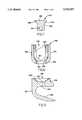
- FIG. 4is a side view of a bone screw which is an aspect of the present invention.
- FIG. 5is a side view of a lamina hook which is an aspect of the present invention.
- FIG. 6is a side view of the rod receiving member of present invention.
- FIG. 7is a side view of the post member which is an aspect of the present invention.
- FIG. 8is a side view of a top locking nut which is an aspect of the present invention.
- FIG. 9is a side cross-sectional view of an embodiment of the present invention, a lamina hook embodiment, in its fully assembled disposition in which a dowel is utilized to retain the post member in the base member, and a rod is securely locked therein;
- FIG. 10is a side cross-sectional view of an embodiment of the present invention, a lamina hook embodiment, in its fully assembled disposition having a rod securely locked therein, the plane of the cross-section being perpendicular to the cross-sectional plane of FIG. 9;
- FIG. 11is a side cross-sectional view of an embodiment of the present invention, a bone screw embodiment, in its fully assembled disposition in which the post member is sweat locked into the recess of the base member.
- the screw 100comprises a standard shaft portion 102 of a bone screw, having a threading 104 provided thereon.
- the upper portion 106 of the screw 100comprises a recess 108 which is divided into a cylindrical (which may be tapered) lower portion 110, and a curved (preferably with a constant radius of curvature) upper portion 112.
- the upper portion 106 of the screwalso includes a through hole 114 which extends through the screw transverse to the long axis of the shaft, and through the lower portion 110 of the recess 108 formed in the top thereof.
- a lamina hook 120 of the present inventionis provided in a side cross-section view.
- the hook 120comprises a lower blade portion 122 which is designed to seat under the lamina, a curved portion 124 which is designed to cup the lateral edge of the lamina, and a upper portion 126 which forms a base for the polyaxial head (see FIG. 6).
- the upper portion 126 of the hook 120is substantially similar to the upper portion 106 of the screw 100 shown in FIG. 4.
- the base 106therefore includes a recess 128 which is divided into a cylindrical (which may be tapered) lower portion 130, and a curved (preferably with a constant radius of curvature) upper portion 132.
- the upper portion 126 of the hook 120also includes a through hole 134 which extends through the screw transverse to the long axis of the recess 128, and through the lower portion 130 of the recess 128 formed in the top thereof.
- the base implant devicehaving the recess, may be either a hook or a screw (or any other implant device for which a polyaxial head is desireable).
- the rod receiving head 140 of the polyaxial hookis provided in a side cross-section view.
- the head 140is a tubular element having a central axial bore 142.
- the exterior surface 144 of the tubeis substantially uniform at the top 146 of the head 140, but inwardly curved at the bottom 148 thereof.
- the radius of curvature of this bottom exterior surface 148is preferably constant (spherical) and preferably is equal to the radius of the upper portion 112,132 of the recess 108,128 in the top of the screw 100 or hook 120, respectively.
- the interior surface 150 of the head portion 140has an inwardly curved lower portion 152 which is preferably also curved with a constant radius, and even more preferably substantially concentrically curved with respect to the outer curvature of the lower exterior surface 148.
- the head 140further comprises a rod receptical defined by a channel groove 154.
- the depth of the channel groove 154is determined in proportion to the dimensions of the post element seated therein in a relationship more fully set forth hereinbelow (see FIGS. 9-11, and discussions pertaining thereto).
- a threading 156may be provided on the interior (or, not shown, the exterior) surface of the upper portion of the head 140 to receive a locking nut (see FIG. 8).
- a post element 160 of the present inventionis provided is a side view.
- the post member 160has a lower portion 162 which is designed to seat in the lower portion 110,130 of the recess 108,128 of the base member.
- the lower portion 162 of the postfurther includes a transverse hole 164 such that when said lower portion 162 is positioned in the recess 108,128 of the base member, the transverse holes 114,134 of the base member and the lower portion 162 of the post member 160 are co-linear.
- the post member 160is securely retainable in the recess 108,128 of the base member by means of a locking dowel (see FIGS. 9 and 10) which is insertable into the co-linear transverse hole formed by the above-mentioned transverse holes 114,134 of the base and post 160 members.
- the upper portion 166 of the post member 160includes a widened annular section.
- the upper surface 168 of this sectionmay be flat or roughened to provide an enhanced frictional dynamic with a metal rod (such as is to be pressed against it--as set forth more fully hereinbelow).
- the lower surface 170 of the widened annular sectiondefines a cross-section (taken along the axial length of the post member) which is curvate, and preferably has a constant radius of curvature, and most preferably has a radius of curvature equal to the interior curvate surface 152 of the head 140.
- one possible locking nut 180is provided in a side cross-section view.
- the locking nut 180requires a threading 182 which can mate with and be advanced along the threading 156 of the head portion, so as to lock a rod in the channel 154 (thereinalso providing a downward force onto the top surface of the post 160).
- This locking nutcomprises a central set screw portion 184 and an outer rim portion 186 which seats around the upper portion of the set screw 184 and floats independently until the set screw 184 is fully locked in place on the head 160.
- the rod receiving memberis a cylindrical element having a central bore and a channel formed transversely therethrough, said channel dividing the upper portion of the member into two upwardly extending curvate elements.
- the upwardly extending membersare preferrably threaded so as to be able to receive a top locking nut of some kind to lock the rod in the channel.
- the base member(herein, the hook 120) includes a recess 128 having an upper portion 132 which is curvate.
- the curvate bottom portion 148 of the head 140seats in this recess on the curvate surface 132.
- the post portion 160is then inserted through the central bore 142 of the head 140 until the lower portion 162 thereof is inserted into the lower portion 130 of the recess 128.
- the transverse holes in both the post 140 and the base member 120are aligned and a dowel 200 is placed into the mutually formed hole, thereby preventing the post 160 from being removed from the recess 128 in the base.
- the headcan polyaxially spin and rotate on top of the base member and relative to the post 160.
- the insertion of a rod 202 into the channel 154 of the head 140, and the subsequent advancement of a locking nut 180 onto the head 140 (and thereonto the rod 202)provides a downward force onto the top of the post 160 relative to the head 140. This force, in turn causes the head 140 to rise relative to the post 160 causing the interior surface 152 of the head 140 to crush lock to the undersurface 170 of the post 160.
- a second embodiment of the present inventionis shown in a cross-section view.
- this embodimentdiffers from the one set forth above insofar as it does not require a dowel to hold the post in the recess because the post 160 is "sweat locked" into the recess 128 by means of thermal contraction and expansion, i.e., the post is cooled to a relatively low temperature - therein causing a slight decrease in its diameter as compared with room temperature, and the base member (herein the screw) is raised to a high relative temperature to cause the recess 128 to expand, and subsequently inserting the post into the recess prior to the equilibration of relative temperatures.
- This "sweat locking" procedureeliminates the need for additional locking means (dowels) and therefore the holes in the post and base.
Landscapes
- Health & Medical Sciences (AREA)
- Orthopedic Medicine & Surgery (AREA)
- Life Sciences & Earth Sciences (AREA)
- Neurology (AREA)
- Surgery (AREA)
- Heart & Thoracic Surgery (AREA)
- Engineering & Computer Science (AREA)
- Biomedical Technology (AREA)
- Nuclear Medicine, Radiotherapy & Molecular Imaging (AREA)
- Medical Informatics (AREA)
- Molecular Biology (AREA)
- Animal Behavior & Ethology (AREA)
- General Health & Medical Sciences (AREA)
- Public Health (AREA)
- Veterinary Medicine (AREA)
- Surgical Instruments (AREA)
Abstract
Description
Claims (10)
Priority Applications (1)
| Application Number | Priority Date | Filing Date | Title |
|---|---|---|---|
| US08/799,721US5752957A (en) | 1997-02-12 | 1997-02-12 | Polyaxial mechanism for use with orthopaedic implant devices |
Applications Claiming Priority (1)
| Application Number | Priority Date | Filing Date | Title |
|---|---|---|---|
| US08/799,721US5752957A (en) | 1997-02-12 | 1997-02-12 | Polyaxial mechanism for use with orthopaedic implant devices |
Publications (1)
| Publication Number | Publication Date |
|---|---|
| US5752957Atrue US5752957A (en) | 1998-05-19 |
Family
ID=25176599
Family Applications (1)
| Application Number | Title | Priority Date | Filing Date |
|---|---|---|---|
| US08/799,721Expired - LifetimeUS5752957A (en) | 1997-02-12 | 1997-02-12 | Polyaxial mechanism for use with orthopaedic implant devices |
Country Status (1)
| Country | Link |
|---|---|
| US (1) | US5752957A (en) |
Cited By (226)
| Publication number | Priority date | Publication date | Assignee | Title |
|---|---|---|---|---|
| US6063090A (en)* | 1996-12-12 | 2000-05-16 | Synthes (U.S.A.) | Device for connecting a longitudinal support to a pedicle screw |
| US6146383A (en)* | 1998-02-02 | 2000-11-14 | Sulzer Orthopadie Ag | Pivotal securing system at a bone screw |
| US6187005B1 (en) | 1998-09-11 | 2001-02-13 | Synthes (Usa) | Variable angle spinal fixation system |
| US6238396B1 (en) | 1999-10-07 | 2001-05-29 | Blackstone Medical, Inc. | Surgical cross-connecting apparatus and related methods |
| US6296642B1 (en)* | 1998-11-09 | 2001-10-02 | Sdgi Holdings, Inc. | Reverse angle thread for preventing splaying in medical devices |
| US6309391B1 (en) | 2000-03-15 | 2001-10-30 | Sdgi Holding, Inc. | Multidirectional pivoting bone screw and fixation system |
| EP1090595A3 (en)* | 1999-10-07 | 2001-11-28 | Stryker Spine SA | Slotted head pedicle screw assembly |
| US6352537B1 (en)* | 1998-09-17 | 2002-03-05 | Electro-Biology, Inc. | Method and apparatus for spinal fixation |
| US6440137B1 (en)* | 2000-04-18 | 2002-08-27 | Andres A. Horvath | Medical fastener cap system |
| US20020120272A1 (en)* | 1998-06-17 | 2002-08-29 | Hansen Yuan | Device for securing spinal rods |
| US6443953B1 (en)* | 2000-02-08 | 2002-09-03 | Cross Medical Products, Inc. | Self-aligning cap nut for use with a spinal rod anchor |
| US6524310B1 (en) | 2000-08-18 | 2003-02-25 | Blackstone Medical, Inc. | Surgical cross-connecting apparatus having locking lever |
| US20030055426A1 (en)* | 2001-09-14 | 2003-03-20 | John Carbone | Biased angulation bone fixation assembly |
| US6540748B2 (en) | 1999-09-27 | 2003-04-01 | Blackstone Medical, Inc. | Surgical screw system and method of use |
| US20030093078A1 (en)* | 2001-09-28 | 2003-05-15 | Stephen Ritland | Connection rod for screw or hook polyaxial system and method of use |
| US20030105460A1 (en)* | 2000-03-15 | 2003-06-05 | Dennis Crandall | Multidirectional pivoting bone screw and fixation system |
| US20030149435A1 (en)* | 2002-02-01 | 2003-08-07 | Baynham Bret O?Apos;Neil | Polyaxial modular skeletal hook |
| US20030171751A1 (en)* | 2002-02-20 | 2003-09-11 | Stephen Ritland | Pedicle screw connector apparatus and method |
| US20030187437A1 (en)* | 2002-03-29 | 2003-10-02 | Depuy Acromed, Inc. | Serrated spinal hook |
| US6641586B2 (en) | 2002-02-01 | 2003-11-04 | Depuy Acromed, Inc. | Closure system for spinal fixation instrumentation |
| US20040002708A1 (en)* | 2002-05-08 | 2004-01-01 | Stephen Ritland | Dynamic fixation device and method of use |
| US20040030337A1 (en)* | 2002-04-09 | 2004-02-12 | Neville Alleyne | Bone fixation apparatus |
| US20040039384A1 (en)* | 2002-08-21 | 2004-02-26 | Boehm Frank H. | Device and method for pertcutaneous placement of lumbar pedicle screws and connecting rods |
| US20040092934A1 (en)* | 2002-04-24 | 2004-05-13 | Howland Robert S. | Multi selective axis spinal fixation system |
| US20040097926A1 (en)* | 2001-03-06 | 2004-05-20 | Sung-Kon Kim | Screw for fixing spine |
| US20040138660A1 (en)* | 2003-01-10 | 2004-07-15 | Serhan Hassan A. | Locking cap assembly for spinal fixation instrumentation |
| US6770075B2 (en) | 2001-05-17 | 2004-08-03 | Robert S. Howland | Spinal fixation apparatus with enhanced axial support and methods for use |
| US20040153077A1 (en)* | 2000-11-10 | 2004-08-05 | Lutz Biedermann | Bone screw |
| US20040153078A1 (en)* | 2003-01-30 | 2004-08-05 | Grinberg Alexander D | Anterior buttress staple |
| US20040181223A1 (en)* | 2001-09-28 | 2004-09-16 | Stephen Ritland | Adjustable rod and connector device and method of use |
| US20040210217A1 (en)* | 2003-04-21 | 2004-10-21 | Baynham Bret O'neil | Bone fixation plate |
| US20040243128A1 (en)* | 2001-05-17 | 2004-12-02 | Howland Robert S. | Selective axis posterior lumbar spinal plating fixation apparatus and methods for use |
| FR2855392A1 (en)* | 2003-05-28 | 2004-12-03 | Spinevision | CONNECTION DEVICE FOR SPINAL OSTESYNTHESIS |
| US20050131545A1 (en)* | 2003-12-10 | 2005-06-16 | Alan Chervitz | Spinal facet implant with spherical implant apposition surface and bone bed and methods of use |
| US20050154391A1 (en)* | 2003-12-30 | 2005-07-14 | Thomas Doherty | Bone anchor assemblies |
| US20050154393A1 (en)* | 2003-12-30 | 2005-07-14 | Thomas Doherty | Bone anchor assemblies and methods of manufacturing bone anchor assemblies |
| US20050171610A1 (en)* | 2004-01-09 | 2005-08-04 | Sdgi Holdings, Inc. | Mobile bearing spinal device and method |
| US20050187548A1 (en)* | 2004-01-13 | 2005-08-25 | Butler Michael S. | Pedicle screw constructs for spine fixation systems |
| US20050192571A1 (en)* | 2004-02-27 | 2005-09-01 | Custom Spine, Inc. | Polyaxial pedicle screw assembly |
| US20050192573A1 (en)* | 2004-02-27 | 2005-09-01 | Custom Spine, Inc. | Biased angle polyaxial pedicle screw assembly |
| US20050192572A1 (en)* | 2004-02-27 | 2005-09-01 | Custom Spine, Inc. | Medialised rod pedicle screw assembly |
| US6945972B2 (en) | 2000-08-24 | 2005-09-20 | Synthes | Apparatus for connecting a bone fastener to a longitudinal rod |
| US20050216000A1 (en)* | 2004-03-22 | 2005-09-29 | Innovative Spinal Technologies | Closure member for a medical implant device |
| US20050228233A1 (en)* | 2000-09-29 | 2005-10-13 | Stephen Ritland | Method and device for microsurgical intermuscular spinal surgery |
| FR2869215A1 (en)* | 2004-04-21 | 2005-10-28 | Kotobuki Ika Shoji Company Ltd | DEVICE FOR MAINTAINING A BAR OR THE LIKE FOR SPINAL OSTEOSYNTHESIS |
| US6966910B2 (en) | 2002-04-05 | 2005-11-22 | Stephen Ritland | Dynamic fixation device and method of use |
| US20050261687A1 (en)* | 2004-04-20 | 2005-11-24 | Laszlo Garamszegi | Pedicle screw assembly |
| US20050273101A1 (en)* | 2004-05-28 | 2005-12-08 | Aesculap Ag & Co. Kg | Bone screw and osteosynthesis device |
| US20060025771A1 (en)* | 2000-08-23 | 2006-02-02 | Jackson Roger P | Helical reverse angle guide and advancement structure with break-off extensions |
| US20060064092A1 (en)* | 2001-05-17 | 2006-03-23 | Howland Robert S | Selective axis serrated rod low profile spinal fixation system |
| US20060079893A1 (en)* | 2000-08-23 | 2006-04-13 | Jackson Roger P | Threadform for medical implant closure |
| US20060083603A1 (en)* | 2000-08-23 | 2006-04-20 | Jackson Roger P | Reverse angled threadform with anti-splay clearance |
| US20060100621A1 (en)* | 2004-11-10 | 2006-05-11 | Jackson Roger P | Polyaxial bone screw with discontinuous helically wound capture connection |
| US20060149235A1 (en)* | 2004-12-20 | 2006-07-06 | Jackson Roger P | Medical implant fastener with nested set screw and method |
| US20060149231A1 (en)* | 2004-12-13 | 2006-07-06 | Rsb Spine Llc | Bone fastener assembly for bone retention apparatus |
| US7141051B2 (en) | 2003-02-05 | 2006-11-28 | Pioneer Laboratories, Inc. | Low profile spinal fixation system |
| US20070055242A1 (en)* | 2005-07-27 | 2007-03-08 | Bailly Frank E | Device for securing spinal rods |
| US20070073291A1 (en)* | 2005-09-12 | 2007-03-29 | Seaspine, Inc. | Implant system for Osteosynthesis |
| US20070093832A1 (en)* | 2004-02-27 | 2007-04-26 | Abdelgany Mahmoud F | Spring-loaded, load sharing polyaxial pedicle screw assembly and method |
| US7214186B2 (en) | 2000-09-29 | 2007-05-08 | Stephen Ritland | Method and device for retractor for microsurgical intermuscular lumbar arthrodesis |
| US20070123870A1 (en)* | 2005-07-18 | 2007-05-31 | Jeon Dong M | Bi-polar screw assembly |
| US20070135824A1 (en)* | 2005-12-09 | 2007-06-14 | O'brien Todd | Suture needle retention device |
| US20070161995A1 (en)* | 2005-10-06 | 2007-07-12 | Trautwein Frank T | Polyaxial Screw |
| US20070161990A1 (en)* | 2005-12-21 | 2007-07-12 | Zimmer Spine, Inc. | Spinal implant hooks and systems |
| US20070179616A1 (en)* | 2006-01-30 | 2007-08-02 | Sdgi Holdings, Inc. | Posterior joint replacement device |
| US20070191945A1 (en)* | 2006-01-30 | 2007-08-16 | Sdgi Holdings, Inc. | Posterior joint replacement device |
| US20070191836A1 (en)* | 2006-01-27 | 2007-08-16 | Sdgi Holdings, Inc. | Methods and devices for a minimally invasive placement of a rod within a patient |
| US20070270813A1 (en)* | 2006-04-12 | 2007-11-22 | Laszlo Garamszegi | Pedicle screw assembly |
| US20070270839A1 (en)* | 2006-04-05 | 2007-11-22 | Dong Myung Jeon | Multi-axial double locking bone screw assembly |
| US20080021456A1 (en)* | 2006-07-21 | 2008-01-24 | Depuy Spine, Inc. | Sacral or iliac cross connector |
| US20080021455A1 (en)* | 2006-07-21 | 2008-01-24 | Depuy Spine, Inc. | Articulating Sacral or Iliac Connector |
| US20080027547A1 (en)* | 2006-07-27 | 2008-01-31 | Warsaw Orthopedic Inc. | Prosthetic device for spinal joint reconstruction |
| US20080045953A1 (en)* | 2006-07-14 | 2008-02-21 | Laszlo Garamszegi | Pedicle screw assembly with inclined surface seat |
| US20080045968A1 (en)* | 2006-08-18 | 2008-02-21 | Warsaw Orthopedic, Inc. | Instruments and Methods for Spinal Surgery |
| US20080119858A1 (en)* | 2006-11-16 | 2008-05-22 | Spine Wave, Inc. | Multi-Axial Spinal Fixation System |
| US20080140134A1 (en)* | 2004-02-27 | 2008-06-12 | Markworth Aaron D | Pedicle dynamic facet arthroplasty system and method |
| US20080177322A1 (en)* | 2006-12-29 | 2008-07-24 | Melissa Davis | Spinal stabilization systems and methods |
| US20080183223A1 (en)* | 2005-09-26 | 2008-07-31 | Jeon Dong M | Hybrid jointed bone screw system |
| US20080288002A1 (en)* | 2006-12-29 | 2008-11-20 | Abbott Spine Inc. | Spinal Stabilization Systems and Methods |
| US7455639B2 (en) | 2004-09-20 | 2008-11-25 | Stephen Ritland | Opposing parallel bladed retractor and method of use |
| US20080300685A1 (en)* | 2007-06-20 | 2008-12-04 | Warsaw Orthopedic, Inc. | Posterior Total Joint Replacement |
| US20090005815A1 (en)* | 2007-06-28 | 2009-01-01 | Scott Ely | Dynamic stabilization system |
| US20090005817A1 (en)* | 2007-04-30 | 2009-01-01 | Adam Friedrich | Flexible Spine Stabilization System |
| US7485132B1 (en)* | 2000-10-06 | 2009-02-03 | Abbott Spine Inc. | Transverse connector with cam activated engagers |
| US20090069849A1 (en)* | 2007-09-10 | 2009-03-12 | Oh Younghoon | Dynamic screw system |
| US20090143823A1 (en)* | 2008-11-13 | 2009-06-04 | Jeon Dong M | Transverse connector system for spinal rods |
| US20090171396A1 (en)* | 2003-04-21 | 2009-07-02 | Baynham Matthew G | Bone fixation plate |
| US20090171395A1 (en)* | 2007-12-28 | 2009-07-02 | Jeon Dong M | Dynamic spinal rod system |
| US20090192548A1 (en)* | 2008-01-25 | 2009-07-30 | Jeon Dong M | Pedicle-laminar dynamic spinal stabilization device |
| US20090194206A1 (en)* | 2008-01-31 | 2009-08-06 | Jeon Dong M | Systems and methods for wrought nickel/titanium alloy flexible spinal rods |
| US20090254125A1 (en)* | 2008-04-03 | 2009-10-08 | Daniel Predick | Top Loading Polyaxial Spine Screw Assembly With One Step Lockup |
| US20090259255A1 (en)* | 2004-01-09 | 2009-10-15 | Warsaw Orthopedic, Inc. | Spinal Arthroplasty Device and Method |
| US7635380B2 (en) | 2007-06-05 | 2009-12-22 | Spartek Medical, Inc. | Bone anchor with a compressor element for receiving a rod for a dynamic stabilization and motion preservation spinal implantation system and method |
| US20090318967A1 (en)* | 2007-01-23 | 2009-12-24 | Dong Myung Jeon | Spacer for use in a surgical operation for spinous process of spine |
| US20100049256A1 (en)* | 2007-01-30 | 2010-02-25 | Dong Myung Jeon | Anterior cerivcal plating system |
| US20100087873A1 (en)* | 2008-10-06 | 2010-04-08 | Warsaw Orthopedics, Inc. | Surgical Connectors for Attaching an Elongated Member to a Bone |
| US20100087874A1 (en)* | 2005-12-21 | 2010-04-08 | Jong Wuk Jang | Pedicle screw |
| US7753939B2 (en) | 2000-06-30 | 2010-07-13 | Stephen Ritland | Polyaxial connection device and method |
| US7766945B2 (en) | 2004-08-10 | 2010-08-03 | Lanx, Inc. | Screw and rod fixation system |
| US7766915B2 (en) | 2004-02-27 | 2010-08-03 | Jackson Roger P | Dynamic fixation assemblies with inner core and outer coil-like member |
| US7901437B2 (en) | 2007-01-26 | 2011-03-08 | Jackson Roger P | Dynamic stabilization member with molded connection |
| US7905907B2 (en) | 2003-10-21 | 2011-03-15 | Theken Spine, Llc | Internal structure stabilization system for spanning three or more structures |
| US7914561B2 (en) | 2002-12-31 | 2011-03-29 | Depuy Spine, Inc. | Resilient bone plate and screw system allowing bi-directional assembly |
| US20110112585A1 (en)* | 2006-11-17 | 2011-05-12 | Biedermann Motech Gmbh | Bone anchoring device |
| US7951170B2 (en) | 2007-05-31 | 2011-05-31 | Jackson Roger P | Dynamic stabilization connecting member with pre-tensioned solid core |
| US7959564B2 (en) | 2006-07-08 | 2011-06-14 | Stephen Ritland | Pedicle seeker and retractor, and methods of use |
| US7963978B2 (en) | 2007-06-05 | 2011-06-21 | Spartek Medical, Inc. | Method for implanting a deflection rod system and customizing the deflection rod system for a particular patient need for dynamic stabilization and motion preservation spinal implantation system |
| US7967826B2 (en) | 2003-10-21 | 2011-06-28 | Theken Spine, Llc | Connector transfer tool for internal structure stabilization systems |
| US7981142B2 (en) | 2002-12-31 | 2011-07-19 | Depuy Spine, Inc. | Bone plate and screw system allowing bi-directional assembly |
| US7993372B2 (en) | 2007-06-05 | 2011-08-09 | Spartek Medical, Inc. | Dynamic stabilization and motion preservation spinal implantation system with a shielded deflection rod system and method |
| US8007518B2 (en) | 2008-02-26 | 2011-08-30 | Spartek Medical, Inc. | Load-sharing component having a deflectable post and method for dynamic stabilization of the spine |
| US8012181B2 (en) | 2008-02-26 | 2011-09-06 | Spartek Medical, Inc. | Modular in-line deflection rod and bone anchor system and method for dynamic stabilization of the spine |
| US8012177B2 (en) | 2007-02-12 | 2011-09-06 | Jackson Roger P | Dynamic stabilization assembly with frusto-conical connection |
| US20110218579A1 (en)* | 2003-06-18 | 2011-09-08 | Jackson Roger P | Polyaxial bone anchor with helical capture connection, insert and dual locking assembly |
| US8016861B2 (en) | 2008-02-26 | 2011-09-13 | Spartek Medical, Inc. | Versatile polyaxial connector assembly and method for dynamic stabilization of the spine |
| US8021396B2 (en) | 2007-06-05 | 2011-09-20 | Spartek Medical, Inc. | Configurable dynamic spinal rod and method for dynamic stabilization of the spine |
| US8021399B2 (en) | 2005-07-19 | 2011-09-20 | Stephen Ritland | Rod extension for extending fusion construct |
| FR2958531A1 (en)* | 2010-04-07 | 2011-10-14 | Michel Timoteo | Device for angular indexing of fixation connector of spinal osteosynthesis equipment with respect to spherical head of pedicular screw in bone body of vertebra, has blind housing to completely limit angular displacements of connector |
| US8043337B2 (en) | 2006-06-14 | 2011-10-25 | Spartek Medical, Inc. | Implant system and method to treat degenerative disorders of the spine |
| US8048115B2 (en) | 2007-06-05 | 2011-11-01 | Spartek Medical, Inc. | Surgical tool and method for implantation of a dynamic bone anchor |
| US8057517B2 (en) | 2008-02-26 | 2011-11-15 | Spartek Medical, Inc. | Load-sharing component having a deflectable post and centering spring and method for dynamic stabilization of the spine |
| US8066739B2 (en) | 2004-02-27 | 2011-11-29 | Jackson Roger P | Tool system for dynamic spinal implants |
| US8083775B2 (en) | 2008-02-26 | 2011-12-27 | Spartek Medical, Inc. | Load-sharing bone anchor having a natural center of rotation and method for dynamic stabilization of the spine |
| US8083772B2 (en) | 2007-06-05 | 2011-12-27 | Spartek Medical, Inc. | Dynamic spinal rod assembly and method for dynamic stabilization of the spine |
| US8092500B2 (en) | 2007-05-01 | 2012-01-10 | Jackson Roger P | Dynamic stabilization connecting member with floating core, compression spacer and over-mold |
| US8092501B2 (en) | 2007-06-05 | 2012-01-10 | Spartek Medical, Inc. | Dynamic spinal rod and method for dynamic stabilization of the spine |
| US8097024B2 (en) | 2008-02-26 | 2012-01-17 | Spartek Medical, Inc. | Load-sharing bone anchor having a deflectable post and method for stabilization of the spine |
| US8100915B2 (en) | 2004-02-27 | 2012-01-24 | Jackson Roger P | Orthopedic implant rod reduction tool set and method |
| US8105368B2 (en) | 2005-09-30 | 2012-01-31 | Jackson Roger P | Dynamic stabilization connecting member with slitted core and outer sleeve |
| US8114134B2 (en) | 2007-06-05 | 2012-02-14 | Spartek Medical, Inc. | Spinal prosthesis having a three bar linkage for motion preservation and dynamic stabilization of the spine |
| US8152810B2 (en) | 2004-11-23 | 2012-04-10 | Jackson Roger P | Spinal fixation tool set and method |
| US8197517B1 (en) | 2007-05-08 | 2012-06-12 | Theken Spine, Llc | Frictional polyaxial screw assembly |
| US20120150239A1 (en)* | 2010-10-15 | 2012-06-14 | Laszlo Garamszegi | Fixation screw assembly |
| US8211155B2 (en) | 2008-02-26 | 2012-07-03 | Spartek Medical, Inc. | Load-sharing bone anchor having a durable compliant member and method for dynamic stabilization of the spine |
| US8257397B2 (en) | 2009-12-02 | 2012-09-04 | Spartek Medical, Inc. | Low profile spinal prosthesis incorporating a bone anchor having a deflectable post and a compound spinal rod |
| US8262571B2 (en) | 2003-05-22 | 2012-09-11 | Stephen Ritland | Intermuscular guide for retractor insertion and method of use |
| US8267979B2 (en) | 2008-02-26 | 2012-09-18 | Spartek Medical, Inc. | Load-sharing bone anchor having a deflectable post and axial spring and method for dynamic stabilization of the spine |
| US8292926B2 (en) | 2005-09-30 | 2012-10-23 | Jackson Roger P | Dynamic stabilization connecting member with elastic core and outer sleeve |
| US8333792B2 (en) | 2008-02-26 | 2012-12-18 | Spartek Medical, Inc. | Load-sharing bone anchor having a deflectable post and method for dynamic stabilization of the spine |
| US8337536B2 (en) | 2008-02-26 | 2012-12-25 | Spartek Medical, Inc. | Load-sharing bone anchor having a deflectable post with a compliant ring and method for stabilization of the spine |
| US8353932B2 (en) | 2005-09-30 | 2013-01-15 | Jackson Roger P | Polyaxial bone anchor assembly with one-piece closure, pressure insert and plastic elongate member |
| US8366745B2 (en) | 2007-05-01 | 2013-02-05 | Jackson Roger P | Dynamic stabilization assembly having pre-compressed spacers with differential displacements |
| US8372150B2 (en) | 2004-01-09 | 2013-02-12 | Warsaw Orthpedic, Inc. | Spinal device and method |
| US8388660B1 (en) | 2006-08-01 | 2013-03-05 | Samy Abdou | Devices and methods for superior fixation of orthopedic devices onto the vertebral column |
| US8430916B1 (en) | 2012-02-07 | 2013-04-30 | Spartek Medical, Inc. | Spinal rod connectors, methods of use, and spinal prosthesis incorporating spinal rod connectors |
| US8444681B2 (en) | 2009-06-15 | 2013-05-21 | Roger P. Jackson | Polyaxial bone anchor with pop-on shank, friction fit retainer and winged insert |
| US20130150890A1 (en)* | 2011-12-08 | 2013-06-13 | Spine Wave, Inc. | Apparatus and devices for percutaneously extending an existing spinal construct |
| US8475498B2 (en) | 2007-01-18 | 2013-07-02 | Roger P. Jackson | Dynamic stabilization connecting member with cord connection |
| US8518085B2 (en) | 2010-06-10 | 2013-08-27 | Spartek Medical, Inc. | Adaptive spinal rod and methods for stabilization of the spine |
| US8545538B2 (en) | 2005-12-19 | 2013-10-01 | M. Samy Abdou | Devices and methods for inter-vertebral orthopedic device placement |
| US8556938B2 (en) | 2009-06-15 | 2013-10-15 | Roger P. Jackson | Polyaxial bone anchor with non-pivotable retainer and pop-on shank, some with friction fit |
| US8591515B2 (en) | 2004-11-23 | 2013-11-26 | Roger P. Jackson | Spinal fixation tool set and method |
| US20140046326A1 (en)* | 2010-02-24 | 2014-02-13 | Wright Medical Technology, Inc. | Orthopedic external fixation device |
| US20140114358A1 (en)* | 2010-04-05 | 2014-04-24 | David L. Brumfield | Fully-Adjustable Bone Fixation Device |
| US8814913B2 (en) | 2002-09-06 | 2014-08-26 | Roger P Jackson | Helical guide and advancement flange with break-off extensions |
| US8845649B2 (en) | 2004-09-24 | 2014-09-30 | Roger P. Jackson | Spinal fixation tool set and method for rod reduction and fastener insertion |
| US8852239B2 (en) | 2013-02-15 | 2014-10-07 | Roger P Jackson | Sagittal angle screw with integral shank and receiver |
| US8870928B2 (en) | 2002-09-06 | 2014-10-28 | Roger P. Jackson | Helical guide and advancement flange with radially loaded lip |
| US8876869B1 (en) | 2009-06-19 | 2014-11-04 | Nuvasive, Inc. | Polyaxial bone screw assembly |
| US8911478B2 (en) | 2012-11-21 | 2014-12-16 | Roger P. Jackson | Splay control closure for open bone anchor |
| US8911477B2 (en) | 2007-10-23 | 2014-12-16 | Roger P. Jackson | Dynamic stabilization member with end plate support and cable core extension |
| US8926670B2 (en) | 2003-06-18 | 2015-01-06 | Roger P. Jackson | Polyaxial bone screw assembly |
| US8926672B2 (en) | 2004-11-10 | 2015-01-06 | Roger P. Jackson | Splay control closure for open bone anchor |
| US8979904B2 (en) | 2007-05-01 | 2015-03-17 | Roger P Jackson | Connecting member with tensioned cord, low profile rigid sleeve and spacer with torsion control |
| US8998959B2 (en) | 2009-06-15 | 2015-04-07 | Roger P Jackson | Polyaxial bone anchors with pop-on shank, fully constrained friction fit retainer and lock and release insert |
| US8998960B2 (en) | 2004-11-10 | 2015-04-07 | Roger P. Jackson | Polyaxial bone screw with helically wound capture connection |
| US8998961B1 (en) | 2009-02-26 | 2015-04-07 | Lanx, Inc. | Spinal rod connector and methods |
| US9050148B2 (en) | 2004-02-27 | 2015-06-09 | Roger P. Jackson | Spinal fixation tool attachment structure |
| US9050139B2 (en) | 2004-02-27 | 2015-06-09 | Roger P. Jackson | Orthopedic implant rod reduction tool set and method |
| US9060813B1 (en) | 2008-02-29 | 2015-06-23 | Nuvasive, Inc. | Surgical fixation system and related methods |
| US9084634B1 (en) | 2010-07-09 | 2015-07-21 | Theken Spine, Llc | Uniplanar screw |
| US9138261B2 (en) | 2010-04-06 | 2015-09-22 | Seaspine, Inc. | System and methods for correcting spinal deformities |
| US9168069B2 (en) | 2009-06-15 | 2015-10-27 | Roger P. Jackson | Polyaxial bone anchor with pop-on shank and winged insert with lower skirt for engaging a friction fit retainer |
| US9179940B2 (en) | 2005-12-06 | 2015-11-10 | Globus Medical, Inc. | System and method for replacement of spinal motion segment |
| US9198692B1 (en) | 2011-02-10 | 2015-12-01 | Nuvasive, Inc. | Spinal fixation anchor |
| US9216039B2 (en) | 2004-02-27 | 2015-12-22 | Roger P. Jackson | Dynamic spinal stabilization assemblies, tool set and method |
| US9216041B2 (en) | 2009-06-15 | 2015-12-22 | Roger P. Jackson | Spinal connecting members with tensioned cords and rigid sleeves for engaging compression inserts |
| US9247962B2 (en) | 2011-08-15 | 2016-02-02 | K2M, Inc. | Laminar hook insertion device |
| US9308027B2 (en) | 2005-05-27 | 2016-04-12 | Roger P Jackson | Polyaxial bone screw with shank articulation pressure insert and method |
| US9387013B1 (en) | 2011-03-01 | 2016-07-12 | Nuvasive, Inc. | Posterior cervical fixation system |
| US9414863B2 (en) | 2005-02-22 | 2016-08-16 | Roger P. Jackson | Polyaxial bone screw with spherical capture, compression insert and alignment and retention structures |
| US9451989B2 (en) | 2007-01-18 | 2016-09-27 | Roger P Jackson | Dynamic stabilization members with elastic and inelastic sections |
| US9451993B2 (en) | 2014-01-09 | 2016-09-27 | Roger P. Jackson | Bi-radial pop-on cervical bone anchor |
| US20160278815A1 (en)* | 2013-03-18 | 2016-09-29 | Fitzbionics Limited | Spinal Implant Assembly |
| US9480517B2 (en) | 2009-06-15 | 2016-11-01 | Roger P. Jackson | Polyaxial bone anchor with pop-on shank, shank, friction fit retainer, winged insert and low profile edge lock |
| US9566092B2 (en) | 2013-10-29 | 2017-02-14 | Roger P. Jackson | Cervical bone anchor with collet retainer and outer locking sleeve |
| US9597119B2 (en) | 2014-06-04 | 2017-03-21 | Roger P. Jackson | Polyaxial bone anchor with polymer sleeve |
| US9636146B2 (en) | 2012-01-10 | 2017-05-02 | Roger P. Jackson | Multi-start closures for open implants |
| US9668771B2 (en) | 2009-06-15 | 2017-06-06 | Roger P Jackson | Soft stabilization assemblies with off-set connector |
| CN106923896A (en)* | 2015-12-29 | 2017-07-07 | 徐丽明 | A kind of medical pedicle screw of new specialty |
| US9717533B2 (en) | 2013-12-12 | 2017-08-01 | Roger P. Jackson | Bone anchor closure pivot-splay control flange form guide and advancement structure |
| US9737340B1 (en) | 2014-09-16 | 2017-08-22 | Nuvasive, Inc. | Adjustable iliac connector |
| US9844398B2 (en) | 2012-05-11 | 2017-12-19 | Orthopediatrics Corporation | Surgical connectors and instrumentation |
| US9907574B2 (en) | 2008-08-01 | 2018-03-06 | Roger P. Jackson | Polyaxial bone anchors with pop-on shank, friction fit fully restrained retainer, insert and tool receiving features |
| US9980753B2 (en) | 2009-06-15 | 2018-05-29 | Roger P Jackson | pivotal anchor with snap-in-place insert having rotation blocking extensions |
| US10039578B2 (en) | 2003-12-16 | 2018-08-07 | DePuy Synthes Products, Inc. | Methods and devices for minimally invasive spinal fixation element placement |
| US10058354B2 (en) | 2013-01-28 | 2018-08-28 | Roger P. Jackson | Pivotal bone anchor assembly with frictional shank head seating surfaces |
| US10064658B2 (en) | 2014-06-04 | 2018-09-04 | Roger P. Jackson | Polyaxial bone anchor with insert guides |
| US20180296249A1 (en)* | 2000-12-08 | 2018-10-18 | Roger P. Jackson | Closure for open-headed medical implant |
| US10194951B2 (en) | 2005-05-10 | 2019-02-05 | Roger P. Jackson | Polyaxial bone anchor with compound articulation and pop-on shank |
| US10258382B2 (en) | 2007-01-18 | 2019-04-16 | Roger P. Jackson | Rod-cord dynamic connection assemblies with slidable bone anchor attachment members along the cord |
| US10299839B2 (en) | 2003-12-16 | 2019-05-28 | Medos International Sárl | Percutaneous access devices and bone anchor assemblies |
| US10349983B2 (en) | 2003-05-22 | 2019-07-16 | Alphatec Spine, Inc. | Pivotal bone anchor assembly with biased bushing for pre-lock friction fit |
| US10363070B2 (en) | 2009-06-15 | 2019-07-30 | Roger P. Jackson | Pivotal bone anchor assemblies with pressure inserts and snap on articulating retainers |
| US10383660B2 (en) | 2007-05-01 | 2019-08-20 | Roger P. Jackson | Soft stabilization assemblies with pretensioned cords |
| US10426521B2 (en)* | 2015-04-24 | 2019-10-01 | Medicrea International | Vertebral osteosynthesis equipment |
| US10507043B1 (en) | 2017-10-11 | 2019-12-17 | Seaspine Orthopedics Corporation | Collet for a polyaxial screw assembly |
| US10543107B2 (en) | 2009-12-07 | 2020-01-28 | Samy Abdou | Devices and methods for minimally invasive spinal stabilization and instrumentation |
| US10548740B1 (en) | 2016-10-25 | 2020-02-04 | Samy Abdou | Devices and methods for vertebral bone realignment |
| US10575961B1 (en) | 2011-09-23 | 2020-03-03 | Samy Abdou | Spinal fixation devices and methods of use |
| US10603083B1 (en) | 2010-07-09 | 2020-03-31 | Theken Spine, Llc | Apparatus and method for limiting a range of angular positions of a screw |
| US10695105B2 (en) | 2012-08-28 | 2020-06-30 | Samy Abdou | Spinal fixation devices and methods of use |
| US10729469B2 (en) | 2006-01-09 | 2020-08-04 | Roger P. Jackson | Flexible spinal stabilization assembly with spacer having off-axis core member |
| US10857003B1 (en) | 2015-10-14 | 2020-12-08 | Samy Abdou | Devices and methods for vertebral stabilization |
| US10918498B2 (en) | 2004-11-24 | 2021-02-16 | Samy Abdou | Devices and methods for inter-vertebral orthopedic device placement |
| US10973648B1 (en) | 2016-10-25 | 2021-04-13 | Samy Abdou | Devices and methods for vertebral bone realignment |
| US11006982B2 (en) | 2012-02-22 | 2021-05-18 | Samy Abdou | Spinous process fixation devices and methods of use |
| US11173040B2 (en) | 2012-10-22 | 2021-11-16 | Cogent Spine, LLC | Devices and methods for spinal stabilization and instrumentation |
| US11179248B2 (en) | 2018-10-02 | 2021-11-23 | Samy Abdou | Devices and methods for spinal implantation |
| US11224464B2 (en) | 2002-05-09 | 2022-01-18 | Roger P. Jackson | Threaded closure with inwardly-facing tool engaging concave radiused structures and axial through-aperture |
| US11229457B2 (en) | 2009-06-15 | 2022-01-25 | Roger P. Jackson | Pivotal bone anchor assembly with insert tool deployment |
| US11234745B2 (en) | 2005-07-14 | 2022-02-01 | Roger P. Jackson | Polyaxial bone screw assembly with partially spherical screw head and twist in place pressure insert |
| US20220087721A1 (en)* | 2020-09-21 | 2022-03-24 | Globus Medical, Inc. | Monoaxial - uniplanar hybrid screw |
| US11419642B2 (en) | 2003-12-16 | 2022-08-23 | Medos International Sarl | Percutaneous access devices and bone anchor assemblies |
| US11890202B2 (en) | 2007-06-20 | 2024-02-06 | 3Spine, Inc. | Spinal osteotomy |
| US12409046B2 (en) | 2022-04-12 | 2025-09-09 | 3Spine, Inc. | Total spinal joint systems with motion moderators |
Citations (5)
| Publication number | Priority date | Publication date | Assignee | Title |
|---|---|---|---|---|
| US5476464A (en)* | 1993-02-25 | 1995-12-19 | Howmedica Gmbh | Device for setting a spine |
| US5591166A (en)* | 1995-03-27 | 1997-01-07 | Smith & Nephew Richards, Inc. | Multi angle bone bolt |
| US5609594A (en)* | 1995-07-13 | 1997-03-11 | Fastenetix Llc | Extending hook and polyaxial coupling element device for use with side loading road fixation devices |
| US5628740A (en)* | 1993-12-23 | 1997-05-13 | Mullane; Thomas S. | Articulating toggle bolt bone screw |
| US5662653A (en)* | 1996-02-22 | 1997-09-02 | Pioneer Laboratories, Inc. | Surgical rod-to-bone attachment |
- 1997
- 1997-02-12USUS08/799,721patent/US5752957A/ennot_activeExpired - Lifetime
Patent Citations (5)
| Publication number | Priority date | Publication date | Assignee | Title |
|---|---|---|---|---|
| US5476464A (en)* | 1993-02-25 | 1995-12-19 | Howmedica Gmbh | Device for setting a spine |
| US5628740A (en)* | 1993-12-23 | 1997-05-13 | Mullane; Thomas S. | Articulating toggle bolt bone screw |
| US5591166A (en)* | 1995-03-27 | 1997-01-07 | Smith & Nephew Richards, Inc. | Multi angle bone bolt |
| US5609594A (en)* | 1995-07-13 | 1997-03-11 | Fastenetix Llc | Extending hook and polyaxial coupling element device for use with side loading road fixation devices |
| US5662653A (en)* | 1996-02-22 | 1997-09-02 | Pioneer Laboratories, Inc. | Surgical rod-to-bone attachment |
Cited By (511)
| Publication number | Priority date | Publication date | Assignee | Title |
|---|---|---|---|---|
| US6063090A (en)* | 1996-12-12 | 2000-05-16 | Synthes (U.S.A.) | Device for connecting a longitudinal support to a pedicle screw |
| US6146383A (en)* | 1998-02-02 | 2000-11-14 | Sulzer Orthopadie Ag | Pivotal securing system at a bone screw |
| US7608095B2 (en) | 1998-06-17 | 2009-10-27 | Howmedica Osteonics Corp. | Device for securing spinal rods |
| US20100268280A1 (en)* | 1998-06-17 | 2010-10-21 | Howmedica Osteonics Corp. | Device for securing spinal rods |
| US8313510B2 (en) | 1998-06-17 | 2012-11-20 | Howmedica Osteonics Corp. | Device for securing spinal rods |
| US8808327B2 (en) | 1998-06-17 | 2014-08-19 | Howmedica Osteonics Corp. | Device for securing spinal rods |
| US8038702B2 (en) | 1998-06-17 | 2011-10-18 | Howmedica Osteonics Corp. | Device for securing spinal rods |
| US7819901B2 (en) | 1998-06-17 | 2010-10-26 | Howmedica Osteonics Corp. | Device for securing spinal rods |
| US7909856B2 (en) | 1998-06-17 | 2011-03-22 | Howmedica Osteonics Corp. | Methods for securing spinal rods |
| US20020120272A1 (en)* | 1998-06-17 | 2002-08-29 | Hansen Yuan | Device for securing spinal rods |
| US7780703B2 (en) | 1998-06-17 | 2010-08-24 | Howmedica Osteonics Corp. | Device for securing spinal rods |
| US6565565B1 (en) | 1998-06-17 | 2003-05-20 | Howmedica Osteonics Corp. | Device for securing spinal rods |
| US6187005B1 (en) | 1998-09-11 | 2001-02-13 | Synthes (Usa) | Variable angle spinal fixation system |
| US6352537B1 (en)* | 1998-09-17 | 2002-03-05 | Electro-Biology, Inc. | Method and apparatus for spinal fixation |
| US6296642B1 (en)* | 1998-11-09 | 2001-10-02 | Sdgi Holdings, Inc. | Reverse angle thread for preventing splaying in medical devices |
| US6540748B2 (en) | 1999-09-27 | 2003-04-01 | Blackstone Medical, Inc. | Surgical screw system and method of use |
| AU771400B2 (en)* | 1999-10-07 | 2004-03-18 | Stryker European Holdings I, Llc | Slotted head pedicle screw assembly |
| US6238396B1 (en) | 1999-10-07 | 2001-05-29 | Blackstone Medical, Inc. | Surgical cross-connecting apparatus and related methods |
| EP1090595A3 (en)* | 1999-10-07 | 2001-11-28 | Stryker Spine SA | Slotted head pedicle screw assembly |
| US6443953B1 (en)* | 2000-02-08 | 2002-09-03 | Cross Medical Products, Inc. | Self-aligning cap nut for use with a spinal rod anchor |
| US6309391B1 (en) | 2000-03-15 | 2001-10-30 | Sdgi Holding, Inc. | Multidirectional pivoting bone screw and fixation system |
| US7322979B2 (en) | 2000-03-15 | 2008-01-29 | Warsaw Orthopedic, Inc. | Multidirectional pivoting bone screw and fixation system |
| US20030105460A1 (en)* | 2000-03-15 | 2003-06-05 | Dennis Crandall | Multidirectional pivoting bone screw and fixation system |
| US6440137B1 (en)* | 2000-04-18 | 2002-08-27 | Andres A. Horvath | Medical fastener cap system |
| US7753939B2 (en) | 2000-06-30 | 2010-07-13 | Stephen Ritland | Polyaxial connection device and method |
| US6524310B1 (en) | 2000-08-18 | 2003-02-25 | Blackstone Medical, Inc. | Surgical cross-connecting apparatus having locking lever |
| US20060083603A1 (en)* | 2000-08-23 | 2006-04-20 | Jackson Roger P | Reverse angled threadform with anti-splay clearance |
| US20060079893A1 (en)* | 2000-08-23 | 2006-04-13 | Jackson Roger P | Threadform for medical implant closure |
| US20060025771A1 (en)* | 2000-08-23 | 2006-02-02 | Jackson Roger P | Helical reverse angle guide and advancement structure with break-off extensions |
| US20110066191A1 (en)* | 2000-08-23 | 2011-03-17 | Jackson Roger P | Threadform for medical implant closure |
| US7837716B2 (en) | 2000-08-23 | 2010-11-23 | Jackson Roger P | Threadform for medical implant closure |
| US6945972B2 (en) | 2000-08-24 | 2005-09-20 | Synthes | Apparatus for connecting a bone fastener to a longitudinal rod |
| US20050251141A1 (en)* | 2000-08-24 | 2005-11-10 | Synthes Usa | Apparatus for connecting a bone fastener to a longitudinal rod |
| US7214186B2 (en) | 2000-09-29 | 2007-05-08 | Stephen Ritland | Method and device for retractor for microsurgical intermuscular lumbar arthrodesis |
| US7166073B2 (en) | 2000-09-29 | 2007-01-23 | Stephen Ritland | Method and device for microsurgical intermuscular spinal surgery |
| US20050228233A1 (en)* | 2000-09-29 | 2005-10-13 | Stephen Ritland | Method and device for microsurgical intermuscular spinal surgery |
| US7485132B1 (en)* | 2000-10-06 | 2009-02-03 | Abbott Spine Inc. | Transverse connector with cam activated engagers |
| US20090138047A1 (en)* | 2000-10-06 | 2009-05-28 | Abbott Spine, Inc. | Transverse connector with cam activated engagers |
| US8062338B2 (en) | 2000-10-06 | 2011-11-22 | Zimmer Spine, Inc. | Transverse connector with cam activated engagers |
| US20110125195A1 (en)* | 2000-10-11 | 2011-05-26 | Lutz Biedermann | Bone Screw |
| US11197694B2 (en) | 2000-11-10 | 2021-12-14 | Biedermann Technologies Gmbh & Co. Kg | Bone screw |
| US7785354B2 (en) | 2000-11-10 | 2010-08-31 | Biedermann Motech Gmbh | Bone screw |
| US20110066189A2 (en)* | 2000-11-10 | 2011-03-17 | Biedermann Motech Gmbh | Bone screw |
| US8864803B2 (en) | 2000-11-10 | 2014-10-21 | Biedermann Technologies Gmbh & Co. Kg | Bone screw |
| US20060106383A1 (en)* | 2000-11-10 | 2006-05-18 | Biedermann Motech Gmbh | Bone screw |
| US20040153077A1 (en)* | 2000-11-10 | 2004-08-05 | Lutz Biedermann | Bone screw |
| US9498256B2 (en) | 2000-11-10 | 2016-11-22 | Biedermann Technologies Gmbh & Co. Kg | Bone screw |
| US9566093B2 (en) | 2000-11-10 | 2017-02-14 | Biedermann Technologies Gmbh & Co. Kg | Bone screw |
| US8945194B2 (en) | 2000-11-10 | 2015-02-03 | Biedermann Technologies Gmbh & Co. Kg | Bone screw |
| US8409260B2 (en) | 2000-11-10 | 2013-04-02 | Biedermann Technologies Gmbh & Co. Kg | Bone screw |
| US10058353B2 (en) | 2000-11-10 | 2018-08-28 | Biedermann Technologies Gmbh & Co. Kg | Bone screw |
| US20180296249A1 (en)* | 2000-12-08 | 2018-10-18 | Roger P. Jackson | Closure for open-headed medical implant |
| US10993745B2 (en)* | 2000-12-08 | 2021-05-04 | Roger P. Jackson | Threaded closure mechanism having a closed body with inwardly-facing concave radiused tool engaging surfaces and a downwardly extending rod-engaging structure |
| US10925647B2 (en)* | 2000-12-08 | 2021-02-23 | Roger P. Jackson | Threaded closure with inwardly-facing tool engaging concave radiused structures and axial through-aperture |
| US7156850B2 (en)* | 2001-03-06 | 2007-01-02 | Sung-Kon Kim | Screw for fixing spine |
| US20040097926A1 (en)* | 2001-03-06 | 2004-05-20 | Sung-Kon Kim | Screw for fixing spine |
| US6770075B2 (en) | 2001-05-17 | 2004-08-03 | Robert S. Howland | Spinal fixation apparatus with enhanced axial support and methods for use |
| US20060064092A1 (en)* | 2001-05-17 | 2006-03-23 | Howland Robert S | Selective axis serrated rod low profile spinal fixation system |
| US20050216005A1 (en)* | 2001-05-17 | 2005-09-29 | Howland Robert S | Selective axis anchor screw posterior lumbar plating system |
| US20040243128A1 (en)* | 2001-05-17 | 2004-12-02 | Howland Robert S. | Selective axis posterior lumbar spinal plating fixation apparatus and methods for use |
| US8870930B2 (en) | 2001-09-14 | 2014-10-28 | Stryker Spine | Methods for stabilizing bone using spinal fixation devices |
| US20040243126A1 (en)* | 2001-09-14 | 2004-12-02 | Stryker Spine | Methods for stabilizing bone using spinal fixation devices |
| US6974460B2 (en) | 2001-09-14 | 2005-12-13 | Stryker Spine | Biased angulation bone fixation assembly |
| US20030055426A1 (en)* | 2001-09-14 | 2003-03-20 | John Carbone | Biased angulation bone fixation assembly |
| US9662144B2 (en) | 2001-09-14 | 2017-05-30 | Stryker European Holdings I, Llc | Stabilizing bone using spinal fixation devices and systems |
| US8506600B2 (en) | 2001-09-14 | 2013-08-13 | Stryker Spine | Methods for stabilizing bone using spinal fixation devices |
| US10517646B2 (en) | 2001-09-14 | 2019-12-31 | Stryker European Holdings I, Llc | Stabilizing bone using spinal fixation devices and systems |
| US9622790B2 (en) | 2001-09-19 | 2017-04-18 | Warsaw Orthopedic, Inc. | Rod extension for extending fusion construct |
| US7985245B2 (en) | 2001-09-28 | 2011-07-26 | Stephen Ritland | Connection rod for screw or hook polyaxial system and method of use |
| US7695498B2 (en) | 2001-09-28 | 2010-04-13 | Stephen Ritland | Connection rod for screw or hook polyaxial system and method of use |
| US6991632B2 (en) | 2001-09-28 | 2006-01-31 | Stephen Ritland | Adjustable rod and connector device and method of use |
| US7207992B2 (en) | 2001-09-28 | 2007-04-24 | Stephen Ritland | Connection rod for screw or hook polyaxial system and method of use |
| US20040181223A1 (en)* | 2001-09-28 | 2004-09-16 | Stephen Ritland | Adjustable rod and connector device and method of use |
| US20030093078A1 (en)* | 2001-09-28 | 2003-05-15 | Stephen Ritland | Connection rod for screw or hook polyaxial system and method of use |
| US7655025B2 (en) | 2001-09-28 | 2010-02-02 | Stephen Ritland | Adjustable rod and connector device and method of use |
| US6932817B2 (en) | 2002-02-01 | 2005-08-23 | Innovative Spinal Design | Polyaxial modular skeletal hook |
| WO2003065912A3 (en)* | 2002-02-01 | 2003-11-27 | Brett O'neil Baynham | Polyaxial modular skeletal hook |
| US20030149435A1 (en)* | 2002-02-01 | 2003-08-07 | Baynham Bret O?Apos;Neil | Polyaxial modular skeletal hook |
| US6641586B2 (en) | 2002-02-01 | 2003-11-04 | Depuy Acromed, Inc. | Closure system for spinal fixation instrumentation |
| US7763047B2 (en) | 2002-02-20 | 2010-07-27 | Stephen Ritland | Pedicle screw connector apparatus and method |
| US8221459B2 (en) | 2002-02-20 | 2012-07-17 | Stephen Ritland | Pedicle screw connector apparatus and method |
| US20030171751A1 (en)* | 2002-02-20 | 2003-09-11 | Stephen Ritland | Pedicle screw connector apparatus and method |
| US20030187437A1 (en)* | 2002-03-29 | 2003-10-02 | Depuy Acromed, Inc. | Serrated spinal hook |
| US8932334B2 (en) | 2002-04-05 | 2015-01-13 | Stephen Ritland | Dynamic fixation device and method of use |
| US6966910B2 (en) | 2002-04-05 | 2005-11-22 | Stephen Ritland | Dynamic fixation device and method of use |
| US7294128B2 (en) | 2002-04-09 | 2007-11-13 | Nas Medical Technologies, Inc. | Bone fixation apparatus |
| US20040030337A1 (en)* | 2002-04-09 | 2004-02-12 | Neville Alleyne | Bone fixation apparatus |
| US20040092934A1 (en)* | 2002-04-24 | 2004-05-13 | Howland Robert S. | Multi selective axis spinal fixation system |
| US7314467B2 (en) | 2002-04-24 | 2008-01-01 | Medical Device Advisory Development Group, Llc. | Multi selective axis spinal fixation system |
| US8585739B2 (en) | 2002-05-08 | 2013-11-19 | Stephen Ritland | Dynamic fixation device and method of use |
| US9232967B2 (en) | 2002-05-08 | 2016-01-12 | Stephen Ritland | Dynamic fixation device and method of use |
| US9918744B2 (en) | 2002-05-08 | 2018-03-20 | Stephen Ritland | Dynamic fixation device and method of use |
| US8690922B2 (en) | 2002-05-08 | 2014-04-08 | Stephen Ritland | Dynamic fixation device and method of use |
| US8685062B2 (en) | 2002-05-08 | 2014-04-01 | Stephen Ritland | Dynamic fixation device and method of use |
| US8486111B2 (en) | 2002-05-08 | 2013-07-16 | Stephen Ritland | Dynamic fixation device and method of use |
| US7682375B2 (en) | 2002-05-08 | 2010-03-23 | Stephen Ritland | Dynamic fixation device and method of use |
| US20040002708A1 (en)* | 2002-05-08 | 2004-01-01 | Stephen Ritland | Dynamic fixation device and method of use |
| US11224464B2 (en) | 2002-05-09 | 2022-01-18 | Roger P. Jackson | Threaded closure with inwardly-facing tool engaging concave radiused structures and axial through-aperture |
| US20070016188A1 (en)* | 2002-08-21 | 2007-01-18 | Boehm Frank H Jr | Methods and systems for performing spinal surgery |
| US8202304B2 (en) | 2002-08-21 | 2012-06-19 | Theken Spine, Llc | Methods and systems for performing spinal surgery |
| US20070016198A1 (en)* | 2002-08-21 | 2007-01-18 | Boehm Frank H Jr | Systems, methods and devices for placement of bone anchors and connectors |
| US7306603B2 (en) | 2002-08-21 | 2007-12-11 | Innovative Spinal Technologies | Device and method for percutaneous placement of lumbar pedicle screws and connecting rods |
| US20070016199A1 (en)* | 2002-08-21 | 2007-01-18 | Boehm Frank H Jr | Systems, methods and tools for spinal surgery |
| US20040039384A1 (en)* | 2002-08-21 | 2004-02-26 | Boehm Frank H. | Device and method for pertcutaneous placement of lumbar pedicle screws and connecting rods |
| US8579942B2 (en) | 2002-08-21 | 2013-11-12 | Theken Spine, Llc | Systems, methods and tools for spinal surgery |
| US8382802B2 (en) | 2002-08-21 | 2013-02-26 | Theken Spine, Llc | Systems, methods and devices for placement of bone anchors and connectors |
| US8814913B2 (en) | 2002-09-06 | 2014-08-26 | Roger P Jackson | Helical guide and advancement flange with break-off extensions |
| US8870928B2 (en) | 2002-09-06 | 2014-10-28 | Roger P. Jackson | Helical guide and advancement flange with radially loaded lip |
| US8747441B2 (en) | 2002-12-31 | 2014-06-10 | Depuy Spine, Inc. | Resilient bone plate and screw system allowing bi-directional assembly |
| US7914561B2 (en) | 2002-12-31 | 2011-03-29 | Depuy Spine, Inc. | Resilient bone plate and screw system allowing bi-directional assembly |
| US9351774B2 (en) | 2002-12-31 | 2016-05-31 | DePuy Synthes Products, Inc. | Resilient bone plate and screw system allowing bi-directional assembly |
| US20110144700A1 (en)* | 2002-12-31 | 2011-06-16 | Depuy Spine, Inc. | Resilient bone plate and screw system allowing bi-directional assembly |
| US7981142B2 (en) | 2002-12-31 | 2011-07-19 | Depuy Spine, Inc. | Bone plate and screw system allowing bi-directional assembly |
| US6843791B2 (en) | 2003-01-10 | 2005-01-18 | Depuy Acromed, Inc. | Locking cap assembly for spinal fixation instrumentation |
| US20040138660A1 (en)* | 2003-01-10 | 2004-07-15 | Serhan Hassan A. | Locking cap assembly for spinal fixation instrumentation |
| US7341591B2 (en) | 2003-01-30 | 2008-03-11 | Depuy Spine, Inc. | Anterior buttress staple |
| US20040153078A1 (en)* | 2003-01-30 | 2004-08-05 | Grinberg Alexander D | Anterior buttress staple |
| US7141051B2 (en) | 2003-02-05 | 2006-11-28 | Pioneer Laboratories, Inc. | Low profile spinal fixation system |
| US8348982B2 (en) | 2003-04-21 | 2013-01-08 | Atlas Spine, Inc. | Bone fixation plate |
| US20040210217A1 (en)* | 2003-04-21 | 2004-10-21 | Baynham Bret O'neil | Bone fixation plate |
| US20090171396A1 (en)* | 2003-04-21 | 2009-07-02 | Baynham Matthew G | Bone fixation plate |
| US7481829B2 (en) | 2003-04-21 | 2009-01-27 | Atlas Spine, Inc. | Bone fixation plate |
| US8262571B2 (en) | 2003-05-22 | 2012-09-11 | Stephen Ritland | Intermuscular guide for retractor insertion and method of use |
| US10349983B2 (en) | 2003-05-22 | 2019-07-16 | Alphatec Spine, Inc. | Pivotal bone anchor assembly with biased bushing for pre-lock friction fit |
| US7850718B2 (en)* | 2003-05-28 | 2010-12-14 | Spinevision | Connecting device for spinal osteosynthesis |
| RU2342094C2 (en)* | 2003-05-28 | 2008-12-27 | Спинвизьон | Connecting device for vertebrate osteosynthesis |
| US20070043355A1 (en)* | 2003-05-28 | 2007-02-22 | Stephane Bette | Connecting device for spinal osteosynthesis |
| FR2855392A1 (en)* | 2003-05-28 | 2004-12-03 | Spinevision | CONNECTION DEVICE FOR SPINAL OSTESYNTHESIS |
| AU2004244781B2 (en)* | 2003-05-28 | 2009-12-10 | Spinevision | Connecting device for spinal osteosynthesis |
| WO2004107997A3 (en)* | 2003-05-28 | 2005-02-17 | Spinevision | Connecting device for spinal osteosynthesis |
| US8936623B2 (en) | 2003-06-18 | 2015-01-20 | Roger P. Jackson | Polyaxial bone screw assembly |
| US8926670B2 (en) | 2003-06-18 | 2015-01-06 | Roger P. Jackson | Polyaxial bone screw assembly |
| US20110218579A1 (en)* | 2003-06-18 | 2011-09-08 | Jackson Roger P | Polyaxial bone anchor with helical capture connection, insert and dual locking assembly |
| USRE46431E1 (en) | 2003-06-18 | 2017-06-13 | Roger P Jackson | Polyaxial bone anchor with helical capture connection, insert and dual locking assembly |
| US9144444B2 (en) | 2003-06-18 | 2015-09-29 | Roger P Jackson | Polyaxial bone anchor with helical capture connection, insert and dual locking assembly |
| US7905907B2 (en) | 2003-10-21 | 2011-03-15 | Theken Spine, Llc | Internal structure stabilization system for spanning three or more structures |
| US7967826B2 (en) | 2003-10-21 | 2011-06-28 | Theken Spine, Llc | Connector transfer tool for internal structure stabilization systems |
| US7588590B2 (en)* | 2003-12-10 | 2009-09-15 | Facet Solutions, Inc | Spinal facet implant with spherical implant apposition surface and bone bed and methods of use |
| US20050131545A1 (en)* | 2003-12-10 | 2005-06-16 | Alan Chervitz | Spinal facet implant with spherical implant apposition surface and bone bed and methods of use |
| US10039578B2 (en) | 2003-12-16 | 2018-08-07 | DePuy Synthes Products, Inc. | Methods and devices for minimally invasive spinal fixation element placement |
| US11419642B2 (en) | 2003-12-16 | 2022-08-23 | Medos International Sarl | Percutaneous access devices and bone anchor assemblies |
| US10299839B2 (en) | 2003-12-16 | 2019-05-28 | Medos International Sárl | Percutaneous access devices and bone anchor assemblies |
| US11426216B2 (en) | 2003-12-16 | 2022-08-30 | DePuy Synthes Products, Inc. | Methods and devices for minimally invasive spinal fixation element placement |
| US20050203515A1 (en)* | 2003-12-30 | 2005-09-15 | Thomas Doherty | Bone anchor assemblies |
| US20050154391A1 (en)* | 2003-12-30 | 2005-07-14 | Thomas Doherty | Bone anchor assemblies |
| US20050154393A1 (en)* | 2003-12-30 | 2005-07-14 | Thomas Doherty | Bone anchor assemblies and methods of manufacturing bone anchor assemblies |
| US20050159750A1 (en)* | 2003-12-30 | 2005-07-21 | Thomas Doherty | Bone anchor assemblies and methods of manufacturing bone anchor assemblies |
| US20090259255A1 (en)* | 2004-01-09 | 2009-10-15 | Warsaw Orthopedic, Inc. | Spinal Arthroplasty Device and Method |
| US8372150B2 (en) | 2004-01-09 | 2013-02-12 | Warsaw Orthpedic, Inc. | Spinal device and method |
| US20050171610A1 (en)* | 2004-01-09 | 2005-08-04 | Sdgi Holdings, Inc. | Mobile bearing spinal device and method |
| US8092494B2 (en) | 2004-01-13 | 2012-01-10 | Life Spine, Inc. | Pedicle screw constructs for spine fixation systems |
| US20050187548A1 (en)* | 2004-01-13 | 2005-08-25 | Butler Michael S. | Pedicle screw constructs for spine fixation systems |
| US20080021473A1 (en)* | 2004-01-13 | 2008-01-24 | Life Spine Llc | Pedicle screw constructs for spine fixation systetms |
| US7678137B2 (en) | 2004-01-13 | 2010-03-16 | Life Spine, Inc. | Pedicle screw constructs for spine fixation systems |
| US20110208246A1 (en)* | 2004-02-17 | 2011-08-25 | Alan Chervitz | Spinal Facet Implant with Spherical Implant Apposition Surface and Bone Bed and Methods of Use |
| US7914560B2 (en)* | 2004-02-17 | 2011-03-29 | Gmedelaware 2 Llc | Spinal facet implant with spherical implant apposition surface and bone bed and methods of use |
| US8709046B2 (en)* | 2004-02-17 | 2014-04-29 | Gmedelaware 2 Llc | Spinal facet implant with spherical implant apposition surface and bone bed and methods of use |
| US9050139B2 (en) | 2004-02-27 | 2015-06-09 | Roger P. Jackson | Orthopedic implant rod reduction tool set and method |
| WO2005086649A3 (en)* | 2004-02-27 | 2006-07-27 | Custom Spine Inc | Biased angle polyaxial pedicle screw assembly |
| US8162948B2 (en) | 2004-02-27 | 2012-04-24 | Jackson Roger P | Orthopedic implant rod reduction tool set and method |
| US7766915B2 (en) | 2004-02-27 | 2010-08-03 | Jackson Roger P | Dynamic fixation assemblies with inner core and outer coil-like member |
| EP1725175A4 (en)* | 2004-02-27 | 2008-05-21 | Custom Spine Inc | Polyaxial pedicle screw assembly |
| US11291480B2 (en) | 2004-02-27 | 2022-04-05 | Nuvasive, Inc. | Spinal fixation tool attachment structure |
| US20050192571A1 (en)* | 2004-02-27 | 2005-09-01 | Custom Spine, Inc. | Polyaxial pedicle screw assembly |
| US8377067B2 (en) | 2004-02-27 | 2013-02-19 | Roger P. Jackson | Orthopedic implant rod reduction tool set and method |
| US8894657B2 (en) | 2004-02-27 | 2014-11-25 | Roger P. Jackson | Tool system for dynamic spinal implants |
| US8652178B2 (en) | 2004-02-27 | 2014-02-18 | Custom Spine, Inc. | Polyaxial pedicle screw assembly and method |
| US7819902B2 (en) | 2004-02-27 | 2010-10-26 | Custom Spine, Inc. | Medialised rod pedicle screw assembly |
| US9216039B2 (en) | 2004-02-27 | 2015-12-22 | Roger P. Jackson | Dynamic spinal stabilization assemblies, tool set and method |
| JP2007523723A (en)* | 2004-02-27 | 2007-08-23 | カスタム スパイン インコーポレーテッド | Multi-axis pattern joining screw assembly having deflection angle |
| JP2007523724A (en)* | 2004-02-27 | 2007-08-23 | カスタム スパイン インコーポレーテッド | Handle assembly screw assembly having rods with center axis aligned |
| US7862594B2 (en) | 2004-02-27 | 2011-01-04 | Custom Spine, Inc. | Polyaxial pedicle screw assembly |
| US20110034258A1 (en)* | 2004-02-27 | 2011-02-10 | Custom Spine, Inc | Polyaxial Pedicle Screw Assembly and Method |
| US7892257B2 (en)* | 2004-02-27 | 2011-02-22 | Custom Spine, Inc. | Spring loaded, load sharing polyaxial pedicle screw assembly and method |
| US7763057B2 (en)* | 2004-02-27 | 2010-07-27 | Custom Spine, Inc. | Biased angle polyaxial pedicle screw assembly |
| US20110054546A1 (en)* | 2004-02-27 | 2011-03-03 | Custom Spine, Inc | Polyaxial Pedicle Screw Assembly |
| JP2007523725A (en)* | 2004-02-27 | 2007-08-23 | カスタム スパイン インコーポレーテッド | Multi-axis pattern joining screw assembly |
| US20080140134A1 (en)* | 2004-02-27 | 2008-06-12 | Markworth Aaron D | Pedicle dynamic facet arthroplasty system and method |
| US9532815B2 (en) | 2004-02-27 | 2017-01-03 | Roger P. Jackson | Spinal fixation tool set and method |
| US8100915B2 (en) | 2004-02-27 | 2012-01-24 | Jackson Roger P | Orthopedic implant rod reduction tool set and method |
| US20050192573A1 (en)* | 2004-02-27 | 2005-09-01 | Custom Spine, Inc. | Biased angle polyaxial pedicle screw assembly |
| US8394133B2 (en) | 2004-02-27 | 2013-03-12 | Roger P. Jackson | Dynamic fixation assemblies with inner core and outer coil-like member |
| US8097020B2 (en) | 2004-02-27 | 2012-01-17 | Custom Spine, Inc. | Pedicle dynamic facet arthroplasty system and method |
| US20050192572A1 (en)* | 2004-02-27 | 2005-09-01 | Custom Spine, Inc. | Medialised rod pedicle screw assembly |
| US9050148B2 (en) | 2004-02-27 | 2015-06-09 | Roger P. Jackson | Spinal fixation tool attachment structure |
| US20110112582A1 (en)* | 2004-02-27 | 2011-05-12 | Custom Spine, Inc. | Spring-Loaded, Load Sharing Polyaxial Pedicle Screw Assembly and Method |
| US9636151B2 (en) | 2004-02-27 | 2017-05-02 | Roger P Jackson | Orthopedic implant rod reduction tool set and method |
| US9662143B2 (en) | 2004-02-27 | 2017-05-30 | Roger P Jackson | Dynamic fixation assemblies with inner core and outer coil-like member |
| US20070093832A1 (en)* | 2004-02-27 | 2007-04-26 | Abdelgany Mahmoud F | Spring-loaded, load sharing polyaxial pedicle screw assembly and method |
| US8900272B2 (en) | 2004-02-27 | 2014-12-02 | Roger P Jackson | Dynamic fixation assemblies with inner core and outer coil-like member |
| US20070093831A1 (en)* | 2004-02-27 | 2007-04-26 | Abdelgany Mahmoud F | Biased angle polyaxial pedicle screw assembly |
| US9662151B2 (en) | 2004-02-27 | 2017-05-30 | Roger P Jackson | Orthopedic implant rod reduction tool set and method |
| US8066739B2 (en) | 2004-02-27 | 2011-11-29 | Jackson Roger P | Tool system for dynamic spinal implants |
| EP1722700A4 (en)* | 2004-02-27 | 2008-05-21 | Custom Spine Inc | Biased angle polyaxial pedicle screw assembly |
| US7163539B2 (en)* | 2004-02-27 | 2007-01-16 | Custom Spine, Inc. | Biased angle polyaxial pedicle screw assembly |
| US11147597B2 (en) | 2004-02-27 | 2021-10-19 | Roger P Jackson | Dynamic spinal stabilization assemblies, tool set and method |
| US9918751B2 (en) | 2004-02-27 | 2018-03-20 | Roger P. Jackson | Tool system for dynamic spinal implants |
| US8439954B2 (en)* | 2004-02-27 | 2013-05-14 | Custom Spine, Inc. | Spring-loaded, load sharing polyaxial pedicle screw assembly and method |
| WO2005086651A3 (en)* | 2004-02-27 | 2006-09-08 | Custom Spine Inc | Polyaxial pedicle screw assembly |
| US11648039B2 (en) | 2004-02-27 | 2023-05-16 | Roger P. Jackson | Spinal fixation tool attachment structure |
| US9055978B2 (en) | 2004-02-27 | 2015-06-16 | Roger P. Jackson | Orthopedic implant rod reduction tool set and method |
| US8292892B2 (en) | 2004-02-27 | 2012-10-23 | Jackson Roger P | Orthopedic implant rod reduction tool set and method |
| US10485588B2 (en) | 2004-02-27 | 2019-11-26 | Nuvasive, Inc. | Spinal fixation tool attachment structure |
| US20050216000A1 (en)* | 2004-03-22 | 2005-09-29 | Innovative Spinal Technologies | Closure member for a medical implant device |
| US7214227B2 (en) | 2004-03-22 | 2007-05-08 | Innovative Spinal Technologies | Closure member for a medical implant device |
| US7678139B2 (en) | 2004-04-20 | 2010-03-16 | Allez Spine, Llc | Pedicle screw assembly |
| US8273112B2 (en) | 2004-04-20 | 2012-09-25 | Phygen, Llc | Pedicle screw assembly |
| US20100292740A1 (en)* | 2004-04-20 | 2010-11-18 | Laszlo Garamszegi | Pedicle screw assembly |
| US20050261687A1 (en)* | 2004-04-20 | 2005-11-24 | Laszlo Garamszegi | Pedicle screw assembly |
| FR2869215A1 (en)* | 2004-04-21 | 2005-10-28 | Kotobuki Ika Shoji Company Ltd | DEVICE FOR MAINTAINING A BAR OR THE LIKE FOR SPINAL OSTEOSYNTHESIS |
| US7717942B2 (en)* | 2004-05-28 | 2010-05-18 | Aesculap Ag | Bone screw and osteosynthesis device |
| US20050273101A1 (en)* | 2004-05-28 | 2005-12-08 | Aesculap Ag & Co. Kg | Bone screw and osteosynthesis device |
| US7766945B2 (en) | 2004-08-10 | 2010-08-03 | Lanx, Inc. | Screw and rod fixation system |
| US7455639B2 (en) | 2004-09-20 | 2008-11-25 | Stephen Ritland | Opposing parallel bladed retractor and method of use |
| US8845649B2 (en) | 2004-09-24 | 2014-09-30 | Roger P. Jackson | Spinal fixation tool set and method for rod reduction and fastener insertion |
| WO2006052346A3 (en)* | 2004-11-10 | 2007-01-11 | Roger P Jackson | Polyaxial bone screw with discontinuously threaded capture connection |
| US9743957B2 (en) | 2004-11-10 | 2017-08-29 | Roger P. Jackson | Polyaxial bone screw with shank articulation pressure insert and method |
| US7572279B2 (en) | 2004-11-10 | 2009-08-11 | Jackson Roger P | Polyaxial bone screw with discontinuous helically wound capture connection |
| US8636777B2 (en) | 2004-11-10 | 2014-01-28 | Roger P. Jackson | Polyaxial bone screw with discontinuous helically wound capture connection |
| US8998960B2 (en) | 2004-11-10 | 2015-04-07 | Roger P. Jackson | Polyaxial bone screw with helically wound capture connection |
| US11278327B2 (en) | 2004-11-10 | 2022-03-22 | Roger P. Jackson | Pivotal bone anchor receiver assembly with unitary and multi-part interchangeable threaded closures |
| US11147591B2 (en) | 2004-11-10 | 2021-10-19 | Roger P Jackson | Pivotal bone anchor receiver assembly with threaded closure |
| US8926672B2 (en) | 2004-11-10 | 2015-01-06 | Roger P. Jackson | Splay control closure for open bone anchor |
| US20090287261A1 (en)* | 2004-11-10 | 2009-11-19 | Jackson Roger P | Polyaxial bone screw with discontinuous helically wound capture connection |
| US11564714B2 (en) | 2004-11-10 | 2023-01-31 | Roger P. Jackson | Spinal stabilization implant assemblies with interchangeable threaded closures |
| US20060100621A1 (en)* | 2004-11-10 | 2006-05-11 | Jackson Roger P | Polyaxial bone screw with discontinuous helically wound capture connection |
| US9629669B2 (en) | 2004-11-23 | 2017-04-25 | Roger P. Jackson | Spinal fixation tool set and method |
| US9211150B2 (en) | 2004-11-23 | 2015-12-15 | Roger P. Jackson | Spinal fixation tool set and method |
| US9522021B2 (en) | 2004-11-23 | 2016-12-20 | Roger P. Jackson | Polyaxial bone anchor with retainer with notch for mono-axial motion |
| US8591515B2 (en) | 2004-11-23 | 2013-11-26 | Roger P. Jackson | Spinal fixation tool set and method |
| US10039577B2 (en) | 2004-11-23 | 2018-08-07 | Roger P Jackson | Bone anchor receiver with horizontal radiused tool attachment structures and parallel planar outer surfaces |
| US8152810B2 (en) | 2004-11-23 | 2012-04-10 | Jackson Roger P | Spinal fixation tool set and method |
| US8273089B2 (en) | 2004-11-23 | 2012-09-25 | Jackson Roger P | Spinal fixation tool set and method |
| US11389214B2 (en) | 2004-11-23 | 2022-07-19 | Roger P. Jackson | Spinal fixation tool set and method |
| US10918498B2 (en) | 2004-11-24 | 2021-02-16 | Samy Abdou | Devices and methods for inter-vertebral orthopedic device placement |
| US11992423B2 (en) | 2004-11-24 | 2024-05-28 | Samy Abdou | Devices and methods for inter-vertebral orthopedic device placement |
| US11096799B2 (en) | 2004-11-24 | 2021-08-24 | Samy Abdou | Devices and methods for inter-vertebral orthopedic device placement |
| US7578833B2 (en) | 2004-12-13 | 2009-08-25 | Dr. Robert S. Bray, Jr. | Bone fastener assembly for bone retention apparatus |
| US20060149231A1 (en)* | 2004-12-13 | 2006-07-06 | Rsb Spine Llc | Bone fastener assembly for bone retention apparatus |
| US7204838B2 (en) | 2004-12-20 | 2007-04-17 | Jackson Roger P | Medical implant fastener with nested set screw and method |
| US20060149235A1 (en)* | 2004-12-20 | 2006-07-06 | Jackson Roger P | Medical implant fastener with nested set screw and method |
| USRE47551E1 (en) | 2005-02-22 | 2019-08-06 | Roger P. Jackson | Polyaxial bone screw with spherical capture, compression insert and alignment and retention structures |
| US9414863B2 (en) | 2005-02-22 | 2016-08-16 | Roger P. Jackson | Polyaxial bone screw with spherical capture, compression insert and alignment and retention structures |
| US10194951B2 (en) | 2005-05-10 | 2019-02-05 | Roger P. Jackson | Polyaxial bone anchor with compound articulation and pop-on shank |
| US9308027B2 (en) | 2005-05-27 | 2016-04-12 | Roger P Jackson | Polyaxial bone screw with shank articulation pressure insert and method |
| US11234745B2 (en) | 2005-07-14 | 2022-02-01 | Roger P. Jackson | Polyaxial bone screw assembly with partially spherical screw head and twist in place pressure insert |
| US20070123870A1 (en)* | 2005-07-18 | 2007-05-31 | Jeon Dong M | Bi-polar screw assembly |
| US8021399B2 (en) | 2005-07-19 | 2011-09-20 | Stephen Ritland | Rod extension for extending fusion construct |
| US8845694B2 (en) | 2005-07-19 | 2014-09-30 | Warsaw Orthopedic, Inc. | Rod extension for extending fusion construct |
| US20070055242A1 (en)* | 2005-07-27 | 2007-03-08 | Bailly Frank E | Device for securing spinal rods |
| US7766946B2 (en) | 2005-07-27 | 2010-08-03 | Frank Emile Bailly | Device for securing spinal rods |
| US7695497B2 (en) | 2005-09-12 | 2010-04-13 | Seaspine, Inc. | Implant system for osteosynthesis |
| US20070073291A1 (en)* | 2005-09-12 | 2007-03-29 | Seaspine, Inc. | Implant system for Osteosynthesis |
| US20080183223A1 (en)* | 2005-09-26 | 2008-07-31 | Jeon Dong M | Hybrid jointed bone screw system |
| US8353932B2 (en) | 2005-09-30 | 2013-01-15 | Jackson Roger P | Polyaxial bone anchor assembly with one-piece closure, pressure insert and plastic elongate member |
| US8696711B2 (en) | 2005-09-30 | 2014-04-15 | Roger P. Jackson | Polyaxial bone anchor assembly with one-piece closure, pressure insert and plastic elongate member |
| US8292926B2 (en) | 2005-09-30 | 2012-10-23 | Jackson Roger P | Dynamic stabilization connecting member with elastic core and outer sleeve |
| US8105368B2 (en) | 2005-09-30 | 2012-01-31 | Jackson Roger P | Dynamic stabilization connecting member with slitted core and outer sleeve |
| US8591560B2 (en) | 2005-09-30 | 2013-11-26 | Roger P. Jackson | Dynamic stabilization connecting member with elastic core and outer sleeve |
| US8613760B2 (en) | 2005-09-30 | 2013-12-24 | Roger P. Jackson | Dynamic stabilization connecting member with slitted core and outer sleeve |
| US8470001B2 (en) | 2005-10-06 | 2013-06-25 | Paradigm Spine, Llc | Polyaxial screw |
| US20070161995A1 (en)* | 2005-10-06 | 2007-07-12 | Trautwein Frank T | Polyaxial Screw |
| US7927359B2 (en) | 2005-10-06 | 2011-04-19 | Paradigm Spine, Llc | Polyaxial screw |
| US9179940B2 (en) | 2005-12-06 | 2015-11-10 | Globus Medical, Inc. | System and method for replacement of spinal motion segment |
| US7763038B2 (en)* | 2005-12-09 | 2010-07-27 | O'brien Todd | Suture needle retention device |
| US20070135824A1 (en)* | 2005-12-09 | 2007-06-14 | O'brien Todd | Suture needle retention device |
| US8545538B2 (en) | 2005-12-19 | 2013-10-01 | M. Samy Abdou | Devices and methods for inter-vertebral orthopedic device placement |
| US8308773B2 (en) | 2005-12-21 | 2012-11-13 | Medyssey Co., Ltd. | Pedicle screw |
| US20100087874A1 (en)* | 2005-12-21 | 2010-04-08 | Jong Wuk Jang | Pedicle screw |
| US20070161990A1 (en)* | 2005-12-21 | 2007-07-12 | Zimmer Spine, Inc. | Spinal implant hooks and systems |
| US10729469B2 (en) | 2006-01-09 | 2020-08-04 | Roger P. Jackson | Flexible spinal stabilization assembly with spacer having off-axis core member |
| US7497869B2 (en) | 2006-01-27 | 2009-03-03 | Warsaw Orthopedic, Inc. | Methods and devices for a minimally invasive placement of a rod within a patient |
| US20070191836A1 (en)* | 2006-01-27 | 2007-08-16 | Sdgi Holdings, Inc. | Methods and devices for a minimally invasive placement of a rod within a patient |
| US20070191945A1 (en)* | 2006-01-30 | 2007-08-16 | Sdgi Holdings, Inc. | Posterior joint replacement device |
| US7635389B2 (en) | 2006-01-30 | 2009-12-22 | Warsaw Orthopedic, Inc. | Posterior joint replacement device |
| US20070179616A1 (en)* | 2006-01-30 | 2007-08-02 | Sdgi Holdings, Inc. | Posterior joint replacement device |
| US7811326B2 (en) | 2006-01-30 | 2010-10-12 | Warsaw Orthopedic Inc. | Posterior joint replacement device |
| US20070270839A1 (en)* | 2006-04-05 | 2007-11-22 | Dong Myung Jeon | Multi-axial double locking bone screw assembly |
| US7896902B2 (en) | 2006-04-05 | 2011-03-01 | Dong Myung Jeon | Multi-axial double locking bone screw assembly |
| US20070270813A1 (en)* | 2006-04-12 | 2007-11-22 | Laszlo Garamszegi | Pedicle screw assembly |
| US8172882B2 (en) | 2006-06-14 | 2012-05-08 | Spartek Medical, Inc. | Implant system and method to treat degenerative disorders of the spine |
| US8043337B2 (en) | 2006-06-14 | 2011-10-25 | Spartek Medical, Inc. | Implant system and method to treat degenerative disorders of the spine |
| US7959564B2 (en) | 2006-07-08 | 2011-06-14 | Stephen Ritland | Pedicle seeker and retractor, and methods of use |
| US20080045953A1 (en)* | 2006-07-14 | 2008-02-21 | Laszlo Garamszegi | Pedicle screw assembly with inclined surface seat |
| US8137387B2 (en) | 2006-07-14 | 2012-03-20 | Phygen, LLC. | Pedicle screw assembly with inclined surface seat |
| US20080021455A1 (en)* | 2006-07-21 | 2008-01-24 | Depuy Spine, Inc. | Articulating Sacral or Iliac Connector |
| US20080021456A1 (en)* | 2006-07-21 | 2008-01-24 | Depuy Spine, Inc. | Sacral or iliac cross connector |
| US20080027547A1 (en)* | 2006-07-27 | 2008-01-31 | Warsaw Orthopedic Inc. | Prosthetic device for spinal joint reconstruction |
| US8388660B1 (en) | 2006-08-01 | 2013-03-05 | Samy Abdou | Devices and methods for superior fixation of orthopedic devices onto the vertebral column |
| US20080045968A1 (en)* | 2006-08-18 | 2008-02-21 | Warsaw Orthopedic, Inc. | Instruments and Methods for Spinal Surgery |
| US10448975B2 (en) | 2006-11-16 | 2019-10-22 | Spine Wave, Inc. | Multi-axial spinal fixation system |
| US8162990B2 (en)* | 2006-11-16 | 2012-04-24 | Spine Wave, Inc. | Multi-axial spinal fixation system |
| US8414622B2 (en) | 2006-11-16 | 2013-04-09 | Spine Wave, Inc. | Multi-axial spinal fixation system |
| US9226777B2 (en) | 2006-11-16 | 2016-01-05 | Spine Wave, Inc. | Multi-axial spinal fixation system |
| US9861395B2 (en) | 2006-11-16 | 2018-01-09 | Spine Wave, Inc. | Multi-axial spinal fixation system |
| US8475500B2 (en) | 2006-11-16 | 2013-07-02 | Spine Wave, Inc. | Multi-axial spinal fixation system |
| US20080119858A1 (en)* | 2006-11-16 | 2008-05-22 | Spine Wave, Inc. | Multi-Axial Spinal Fixation System |
| US20080119857A1 (en)* | 2006-11-16 | 2008-05-22 | Spine Wave, Inc. | Multi-Axial Spinal Fixation System |
| US20110112585A1 (en)* | 2006-11-17 | 2011-05-12 | Biedermann Motech Gmbh | Bone anchoring device |
| US8998965B2 (en)* | 2006-11-17 | 2015-04-07 | Biedermann Technologies Gmbh & Co. Kg | Bone anchoring device |
| US20080177322A1 (en)* | 2006-12-29 | 2008-07-24 | Melissa Davis | Spinal stabilization systems and methods |
| US8636783B2 (en) | 2006-12-29 | 2014-01-28 | Zimmer Spine, Inc. | Spinal stabilization systems and methods |
| US20080288002A1 (en)* | 2006-12-29 | 2008-11-20 | Abbott Spine Inc. | Spinal Stabilization Systems and Methods |
| US10258382B2 (en) | 2007-01-18 | 2019-04-16 | Roger P. Jackson | Rod-cord dynamic connection assemblies with slidable bone anchor attachment members along the cord |
| US10470801B2 (en) | 2007-01-18 | 2019-11-12 | Roger P. Jackson | Dynamic spinal stabilization with rod-cord longitudinal connecting members |
| US9451989B2 (en) | 2007-01-18 | 2016-09-27 | Roger P Jackson | Dynamic stabilization members with elastic and inelastic sections |
| US8475498B2 (en) | 2007-01-18 | 2013-07-02 | Roger P. Jackson | Dynamic stabilization connecting member with cord connection |
| US20090318967A1 (en)* | 2007-01-23 | 2009-12-24 | Dong Myung Jeon | Spacer for use in a surgical operation for spinous process of spine |
| US9101404B2 (en) | 2007-01-26 | 2015-08-11 | Roger P. Jackson | Dynamic stabilization connecting member with molded connection |
| US9439683B2 (en) | 2007-01-26 | 2016-09-13 | Roger P Jackson | Dynamic stabilization member with molded connection |
| US7901437B2 (en) | 2007-01-26 | 2011-03-08 | Jackson Roger P | Dynamic stabilization member with molded connection |
| US20100049256A1 (en)* | 2007-01-30 | 2010-02-25 | Dong Myung Jeon | Anterior cerivcal plating system |
| US8012177B2 (en) | 2007-02-12 | 2011-09-06 | Jackson Roger P | Dynamic stabilization assembly with frusto-conical connection |
| US8506599B2 (en) | 2007-02-12 | 2013-08-13 | Roger P. Jackson | Dynamic stabilization assembly with frusto-conical connection |
| US20090005817A1 (en)* | 2007-04-30 | 2009-01-01 | Adam Friedrich | Flexible Spine Stabilization System |
| US9220538B2 (en) | 2007-04-30 | 2015-12-29 | Globus Medical, Inc. | Flexible element for spine stabilization system |
| US9339297B2 (en) | 2007-04-30 | 2016-05-17 | Globus Medical, Inc. | Flexible spine stabilization system |
| US9211142B2 (en) | 2007-04-30 | 2015-12-15 | Globus Medical, Inc. | Flexible element for spine stabilization system |
| US8465526B2 (en) | 2007-04-30 | 2013-06-18 | Globus Medical, Inc. | Flexible spine stabilization system |
| US8366745B2 (en) | 2007-05-01 | 2013-02-05 | Jackson Roger P | Dynamic stabilization assembly having pre-compressed spacers with differential displacements |
| US8979904B2 (en) | 2007-05-01 | 2015-03-17 | Roger P Jackson | Connecting member with tensioned cord, low profile rigid sleeve and spacer with torsion control |
| US8092500B2 (en) | 2007-05-01 | 2012-01-10 | Jackson Roger P | Dynamic stabilization connecting member with floating core, compression spacer and over-mold |
| US10383660B2 (en) | 2007-05-01 | 2019-08-20 | Roger P. Jackson | Soft stabilization assemblies with pretensioned cords |
| US8197517B1 (en) | 2007-05-08 | 2012-06-12 | Theken Spine, Llc | Frictional polyaxial screw assembly |
| US7951170B2 (en) | 2007-05-31 | 2011-05-31 | Jackson Roger P | Dynamic stabilization connecting member with pre-tensioned solid core |
| US8172881B2 (en) | 2007-06-05 | 2012-05-08 | Spartek Medical, Inc. | Dynamic stabilization and motion preservation spinal implantation system and method with a deflection rod mounted in close proximity to a mounting rod |
| US8048122B2 (en) | 2007-06-05 | 2011-11-01 | Spartek Medical, Inc. | Spine implant with a dual deflection rod system including a deflection limiting sheild associated with a bone screw and method |
| US8118842B2 (en) | 2007-06-05 | 2012-02-21 | Spartek Medical, Inc. | Multi-level dynamic stabilization and motion preservation spinal implantation system and method |
| US8114130B2 (en) | 2007-06-05 | 2012-02-14 | Spartek Medical, Inc. | Deflection rod system for spine implant with end connectors and method |
| US8109970B2 (en) | 2007-06-05 | 2012-02-07 | Spartek Medical, Inc. | Deflection rod system with a deflection contouring shield for a spine implant and method |
| US8142480B2 (en) | 2007-06-05 | 2012-03-27 | Spartek Medical, Inc. | Dynamic stabilization and motion preservation spinal implantation system with horizontal deflection rod and articulating vertical rods |
| US8147520B2 (en) | 2007-06-05 | 2012-04-03 | Spartek Medical, Inc. | Horizontally loaded dynamic stabilization and motion preservation spinal implantation system and method |
| US8162987B2 (en) | 2007-06-05 | 2012-04-24 | Spartek Medical, Inc. | Modular spine treatment kit for dynamic stabilization and motion preservation of the spine |
| US8568451B2 (en) | 2007-06-05 | 2013-10-29 | Spartek Medical, Inc. | Bone anchor for receiving a rod for stabilization and motion preservation spinal implantation system and method |
| US8105359B2 (en) | 2007-06-05 | 2012-01-31 | Spartek Medical, Inc. | Deflection rod system for a dynamic stabilization and motion preservation spinal implantation system and method |
| US8177815B2 (en) | 2007-06-05 | 2012-05-15 | Spartek Medical, Inc. | Super-elastic deflection rod for a dynamic stabilization and motion preservation spinal implantation system and method |
| US7635380B2 (en) | 2007-06-05 | 2009-12-22 | Spartek Medical, Inc. | Bone anchor with a compressor element for receiving a rod for a dynamic stabilization and motion preservation spinal implantation system and method |
| US7942900B2 (en) | 2007-06-05 | 2011-05-17 | Spartek Medical, Inc. | Shaped horizontal rod for dynamic stabilization and motion preservation spinal implantation system and method |
| US7963978B2 (en) | 2007-06-05 | 2011-06-21 | Spartek Medical, Inc. | Method for implanting a deflection rod system and customizing the deflection rod system for a particular patient need for dynamic stabilization and motion preservation spinal implantation system |
| US8182515B2 (en) | 2007-06-05 | 2012-05-22 | Spartek Medical, Inc. | Dynamic stabilization and motion preservation spinal implantation system and method |
| US7985243B2 (en) | 2007-06-05 | 2011-07-26 | Spartek Medical, Inc. | Deflection rod system with mount for a dynamic stabilization and motion preservation spinal implantation system and method |
| US7993372B2 (en) | 2007-06-05 | 2011-08-09 | Spartek Medical, Inc. | Dynamic stabilization and motion preservation spinal implantation system with a shielded deflection rod system and method |
| US8002803B2 (en) | 2007-06-05 | 2011-08-23 | Spartek Medical, Inc. | Deflection rod system for a spine implant including an inner rod and an outer shell and method |
| US8002800B2 (en) | 2007-06-05 | 2011-08-23 | Spartek Medical, Inc. | Horizontal rod with a mounting platform for a dynamic stabilization and motion preservation spinal implantation system and method |
| US8012175B2 (en) | 2007-06-05 | 2011-09-06 | Spartek Medical, Inc. | Multi-directional deflection profile for a dynamic stabilization and motion preservation spinal implantation system and method |
| US8021396B2 (en) | 2007-06-05 | 2011-09-20 | Spartek Medical, Inc. | Configurable dynamic spinal rod and method for dynamic stabilization of the spine |
| US8048113B2 (en) | 2007-06-05 | 2011-11-01 | Spartek Medical, Inc. | Deflection rod system with a non-linear deflection to load characteristic for a dynamic stabilization and motion preservation spinal implantation system and method |
| US8048123B2 (en) | 2007-06-05 | 2011-11-01 | Spartek Medical, Inc. | Spine implant with a deflection rod system and connecting linkages and method |
| US8048121B2 (en) | 2007-06-05 | 2011-11-01 | Spartek Medical, Inc. | Spine implant with a defelction rod system anchored to a bone anchor and method |
| US8048128B2 (en) | 2007-06-05 | 2011-11-01 | Spartek Medical, Inc. | Revision system and method for a dynamic stabilization and motion preservation spinal implantation system and method |
| US8317836B2 (en) | 2007-06-05 | 2012-11-27 | Spartek Medical, Inc. | Bone anchor for receiving a rod for stabilization and motion preservation spinal implantation system and method |
| US8298267B2 (en) | 2007-06-05 | 2012-10-30 | Spartek Medical, Inc. | Spine implant with a deflection rod system including a deflection limiting shield associated with a bone screw and method |
| US8114134B2 (en) | 2007-06-05 | 2012-02-14 | Spartek Medical, Inc. | Spinal prosthesis having a three bar linkage for motion preservation and dynamic stabilization of the spine |
| US8048115B2 (en) | 2007-06-05 | 2011-11-01 | Spartek Medical, Inc. | Surgical tool and method for implantation of a dynamic bone anchor |
| US8052721B2 (en) | 2007-06-05 | 2011-11-08 | Spartek Medical, Inc. | Multi-dimensional horizontal rod for a dynamic stabilization and motion preservation spinal implantation system and method |
| US8052722B2 (en) | 2007-06-05 | 2011-11-08 | Spartek Medical, Inc. | Dual deflection rod system for a dynamic stabilization and motion preservation spinal implantation system and method |
| US8057514B2 (en) | 2007-06-05 | 2011-11-15 | Spartek Medical, Inc. | Deflection rod system dimensioned for deflection to a load characteristic for dynamic stabilization and motion preservation spinal implantation system and method |
| US8066747B2 (en) | 2007-06-05 | 2011-11-29 | Spartek Medical, Inc. | Implantation method for a dynamic stabilization and motion preservation spinal implantation system and method |
| US8070775B2 (en) | 2007-06-05 | 2011-12-06 | Spartek Medical, Inc. | Deflection rod system for a dynamic stabilization and motion preservation spinal implantation system and method |
| US8070774B2 (en) | 2007-06-05 | 2011-12-06 | Spartek Medical, Inc. | Reinforced bone anchor for a dynamic stabilization and motion preservation spinal implantation system and method |
| US8070780B2 (en) | 2007-06-05 | 2011-12-06 | Spartek Medical, Inc. | Bone anchor with a yoke-shaped anchor head for a dynamic stabilization and motion preservation spinal implantation system and method |
| US8070776B2 (en) | 2007-06-05 | 2011-12-06 | Spartek Medical, Inc. | Deflection rod system for use with a vertebral fusion implant for dynamic stabilization and motion preservation spinal implantation system and method |
| US8211150B2 (en) | 2007-06-05 | 2012-07-03 | Spartek Medical, Inc. | Dynamic stabilization and motion preservation spinal implantation system and method |
| US8080039B2 (en) | 2007-06-05 | 2011-12-20 | Spartek Medical, Inc. | Anchor system for a spine implantation system that can move about three axes |
| US8083772B2 (en) | 2007-06-05 | 2011-12-27 | Spartek Medical, Inc. | Dynamic spinal rod assembly and method for dynamic stabilization of the spine |
| US8092501B2 (en) | 2007-06-05 | 2012-01-10 | Spartek Medical, Inc. | Dynamic spinal rod and method for dynamic stabilization of the spine |
| US8192469B2 (en) | 2007-06-05 | 2012-06-05 | Spartek Medical, Inc. | Dynamic stabilization and motion preservation spinal implantation system and method with a deflection rod |
| US8105356B2 (en) | 2007-06-05 | 2012-01-31 | Spartek Medical, Inc. | Bone anchor with a curved mounting element for a dynamic stabilization and motion preservation spinal implantation system and method |
| US8182516B2 (en) | 2007-06-05 | 2012-05-22 | Spartek Medical, Inc. | Rod capture mechanism for dynamic stabilization and motion preservation spinal implantation system and method |
| US8864832B2 (en) | 2007-06-20 | 2014-10-21 | Hh Spinal Llc | Posterior total joint replacement |
| US11890202B2 (en) | 2007-06-20 | 2024-02-06 | 3Spine, Inc. | Spinal osteotomy |
| US20080300685A1 (en)* | 2007-06-20 | 2008-12-04 | Warsaw Orthopedic, Inc. | Posterior Total Joint Replacement |
| US20090005815A1 (en)* | 2007-06-28 | 2009-01-01 | Scott Ely | Dynamic stabilization system |
| US20090069849A1 (en)* | 2007-09-10 | 2009-03-12 | Oh Younghoon | Dynamic screw system |
| US8911477B2 (en) | 2007-10-23 | 2014-12-16 | Roger P. Jackson | Dynamic stabilization member with end plate support and cable core extension |
| US20090171395A1 (en)* | 2007-12-28 | 2009-07-02 | Jeon Dong M | Dynamic spinal rod system |
| US20090192548A1 (en)* | 2008-01-25 | 2009-07-30 | Jeon Dong M | Pedicle-laminar dynamic spinal stabilization device |
| US20090194206A1 (en)* | 2008-01-31 | 2009-08-06 | Jeon Dong M | Systems and methods for wrought nickel/titanium alloy flexible spinal rods |
| US8057517B2 (en) | 2008-02-26 | 2011-11-15 | Spartek Medical, Inc. | Load-sharing component having a deflectable post and centering spring and method for dynamic stabilization of the spine |
| US8267979B2 (en) | 2008-02-26 | 2012-09-18 | Spartek Medical, Inc. | Load-sharing bone anchor having a deflectable post and axial spring and method for dynamic stabilization of the spine |
| US8333792B2 (en) | 2008-02-26 | 2012-12-18 | Spartek Medical, Inc. | Load-sharing bone anchor having a deflectable post and method for dynamic stabilization of the spine |
| US8211155B2 (en) | 2008-02-26 | 2012-07-03 | Spartek Medical, Inc. | Load-sharing bone anchor having a durable compliant member and method for dynamic stabilization of the spine |
| US8337536B2 (en) | 2008-02-26 | 2012-12-25 | Spartek Medical, Inc. | Load-sharing bone anchor having a deflectable post with a compliant ring and method for stabilization of the spine |
| US8012181B2 (en) | 2008-02-26 | 2011-09-06 | Spartek Medical, Inc. | Modular in-line deflection rod and bone anchor system and method for dynamic stabilization of the spine |
| US8083775B2 (en) | 2008-02-26 | 2011-12-27 | Spartek Medical, Inc. | Load-sharing bone anchor having a natural center of rotation and method for dynamic stabilization of the spine |
| US8097024B2 (en) | 2008-02-26 | 2012-01-17 | Spartek Medical, Inc. | Load-sharing bone anchor having a deflectable post and method for stabilization of the spine |
| US8048125B2 (en) | 2008-02-26 | 2011-11-01 | Spartek Medical, Inc. | Versatile offset polyaxial connector and method for dynamic stabilization of the spine |
| US8007518B2 (en) | 2008-02-26 | 2011-08-30 | Spartek Medical, Inc. | Load-sharing component having a deflectable post and method for dynamic stabilization of the spine |
| US8016861B2 (en) | 2008-02-26 | 2011-09-13 | Spartek Medical, Inc. | Versatile polyaxial connector assembly and method for dynamic stabilization of the spine |
| US8057515B2 (en) | 2008-02-26 | 2011-11-15 | Spartek Medical, Inc. | Load-sharing anchor having a deflectable post and centering spring and method for dynamic stabilization of the spine |
| US9060813B1 (en) | 2008-02-29 | 2015-06-23 | Nuvasive, Inc. | Surgical fixation system and related methods |
| US20090254125A1 (en)* | 2008-04-03 | 2009-10-08 | Daniel Predick | Top Loading Polyaxial Spine Screw Assembly With One Step Lockup |
| US9907574B2 (en) | 2008-08-01 | 2018-03-06 | Roger P. Jackson | Polyaxial bone anchors with pop-on shank, friction fit fully restrained retainer, insert and tool receiving features |
| US20100087873A1 (en)* | 2008-10-06 | 2010-04-08 | Warsaw Orthopedics, Inc. | Surgical Connectors for Attaching an Elongated Member to a Bone |
| US20090143823A1 (en)* | 2008-11-13 | 2009-06-04 | Jeon Dong M | Transverse connector system for spinal rods |
| US8216281B2 (en) | 2008-12-03 | 2012-07-10 | Spartek Medical, Inc. | Low profile spinal prosthesis incorporating a bone anchor having a deflectable post and a compound spinal rod |
| US8998961B1 (en) | 2009-02-26 | 2015-04-07 | Lanx, Inc. | Spinal rod connector and methods |
| US11229457B2 (en) | 2009-06-15 | 2022-01-25 | Roger P. Jackson | Pivotal bone anchor assembly with insert tool deployment |
| US9480517B2 (en) | 2009-06-15 | 2016-11-01 | Roger P. Jackson | Polyaxial bone anchor with pop-on shank, shank, friction fit retainer, winged insert and low profile edge lock |
| US9980753B2 (en) | 2009-06-15 | 2018-05-29 | Roger P Jackson | pivotal anchor with snap-in-place insert having rotation blocking extensions |
| US9168069B2 (en) | 2009-06-15 | 2015-10-27 | Roger P. Jackson | Polyaxial bone anchor with pop-on shank and winged insert with lower skirt for engaging a friction fit retainer |
| US9216041B2 (en) | 2009-06-15 | 2015-12-22 | Roger P. Jackson | Spinal connecting members with tensioned cords and rigid sleeves for engaging compression inserts |
| US9668771B2 (en) | 2009-06-15 | 2017-06-06 | Roger P Jackson | Soft stabilization assemblies with off-set connector |
| US8556938B2 (en) | 2009-06-15 | 2013-10-15 | Roger P. Jackson | Polyaxial bone anchor with non-pivotable retainer and pop-on shank, some with friction fit |
| US8444681B2 (en) | 2009-06-15 | 2013-05-21 | Roger P. Jackson | Polyaxial bone anchor with pop-on shank, friction fit retainer and winged insert |
| US9504496B2 (en) | 2009-06-15 | 2016-11-29 | Roger P. Jackson | Polyaxial bone anchor with pop-on shank, friction fit retainer and winged insert |
| US8998959B2 (en) | 2009-06-15 | 2015-04-07 | Roger P Jackson | Polyaxial bone anchors with pop-on shank, fully constrained friction fit retainer and lock and release insert |
| US9393047B2 (en) | 2009-06-15 | 2016-07-19 | Roger P. Jackson | Polyaxial bone anchor with pop-on shank and friction fit retainer with low profile edge lock |
| US9717534B2 (en) | 2009-06-15 | 2017-08-01 | Roger P. Jackson | Polyaxial bone anchor with pop-on shank and friction fit retainer with low profile edge lock |
| US10363070B2 (en) | 2009-06-15 | 2019-07-30 | Roger P. Jackson | Pivotal bone anchor assemblies with pressure inserts and snap on articulating retainers |
| US9918745B2 (en) | 2009-06-15 | 2018-03-20 | Roger P. Jackson | Polyaxial bone anchor with pop-on shank and winged insert with friction fit compressive collet |
| US8876869B1 (en) | 2009-06-19 | 2014-11-04 | Nuvasive, Inc. | Polyaxial bone screw assembly |
| US8394127B2 (en) | 2009-12-02 | 2013-03-12 | Spartek Medical, Inc. | Low profile spinal prosthesis incorporating a bone anchor having a deflectable post and a compound spinal rod |
| US8372122B2 (en) | 2009-12-02 | 2013-02-12 | Spartek Medical, Inc. | Low profile spinal prosthesis incorporating a bone anchor having a deflectable post and a compound spinal rod |
| US8257397B2 (en) | 2009-12-02 | 2012-09-04 | Spartek Medical, Inc. | Low profile spinal prosthesis incorporating a bone anchor having a deflectable post and a compound spinal rod |
| US11918486B2 (en) | 2009-12-07 | 2024-03-05 | Samy Abdou | Devices and methods for minimally invasive spinal stabilization and instrumentation |
| US10543107B2 (en) | 2009-12-07 | 2020-01-28 | Samy Abdou | Devices and methods for minimally invasive spinal stabilization and instrumentation |
| US10610380B2 (en) | 2009-12-07 | 2020-04-07 | Samy Abdou | Devices and methods for minimally invasive spinal stabilization and instrumentation |
| US10857004B2 (en) | 2009-12-07 | 2020-12-08 | Samy Abdou | Devices and methods for minimally invasive spinal stabilization and instrumentation |
| US10945861B2 (en) | 2009-12-07 | 2021-03-16 | Samy Abdou | Devices and methods for minimally invasive spinal stabilization and instrumentation |
| US9066756B2 (en)* | 2010-02-24 | 2015-06-30 | Wright Medical Technology, Inc. | Orthopedic external fixation device |
| US20140046326A1 (en)* | 2010-02-24 | 2014-02-13 | Wright Medical Technology, Inc. | Orthopedic external fixation device |
| US9717529B2 (en) | 2010-02-24 | 2017-08-01 | Wright Medical Technology, Inc. | Orthopedic external fixation device |
| US20140114358A1 (en)* | 2010-04-05 | 2014-04-24 | David L. Brumfield | Fully-Adjustable Bone Fixation Device |
| US10898231B2 (en) | 2010-04-06 | 2021-01-26 | Seaspine, Inc. | Spinal deformity correction |
| US9949764B2 (en) | 2010-04-06 | 2018-04-24 | Seaspine, Inc. | Spinal deformity correction |
| US12082856B2 (en) | 2010-04-06 | 2024-09-10 | Seaspine, Inc. | Spinal deformity correction |
| US9138261B2 (en) | 2010-04-06 | 2015-09-22 | Seaspine, Inc. | System and methods for correcting spinal deformities |
| FR2958531A1 (en)* | 2010-04-07 | 2011-10-14 | Michel Timoteo | Device for angular indexing of fixation connector of spinal osteosynthesis equipment with respect to spherical head of pedicular screw in bone body of vertebra, has blind housing to completely limit angular displacements of connector |
| US8518085B2 (en) | 2010-06-10 | 2013-08-27 | Spartek Medical, Inc. | Adaptive spinal rod and methods for stabilization of the spine |
| US10206717B1 (en) | 2010-07-09 | 2019-02-19 | Theken Spine, Llc | Apparatus and method for limiting a range of angular positions of a screw |
| US11213324B2 (en) | 2010-07-09 | 2022-01-04 | Theken Spine, Llc | Apparatus and method for limiting a range of angular positions of a screw |
| US9707014B1 (en) | 2010-07-09 | 2017-07-18 | Theken Spine, Llc | Apparatus and method for limiting a range of angular positions of a screw |
| US10603083B1 (en) | 2010-07-09 | 2020-03-31 | Theken Spine, Llc | Apparatus and method for limiting a range of angular positions of a screw |
| US9084634B1 (en) | 2010-07-09 | 2015-07-21 | Theken Spine, Llc | Uniplanar screw |
| US11147594B1 (en) | 2010-07-09 | 2021-10-19 | Theken Spine, Llc | Apparatus and method for limiting a range of angular positions of a screw |
| US12042186B1 (en) | 2010-07-09 | 2024-07-23 | Seaspine Orthopedics Corporation | Apparatus and method for limiting a range of angular positions of a screw |
| US20120150239A1 (en)* | 2010-10-15 | 2012-06-14 | Laszlo Garamszegi | Fixation screw assembly |
| US9510867B2 (en)* | 2010-10-15 | 2016-12-06 | Phygen, Llc | Fixation screw assembly |
| US10433875B2 (en) | 2010-10-15 | 2019-10-08 | Phygen, Llc | Fixation screw assembly |
| US9198692B1 (en) | 2011-02-10 | 2015-12-01 | Nuvasive, Inc. | Spinal fixation anchor |
| US11123110B2 (en) | 2011-03-01 | 2021-09-21 | Nuvasive, Inc. | Posterior cervical fixation system |
| US10368918B2 (en) | 2011-03-01 | 2019-08-06 | Nuvasive, Inc. | Posterior cervical fixation system |
| US9387013B1 (en) | 2011-03-01 | 2016-07-12 | Nuvasive, Inc. | Posterior cervical fixation system |
| US9956009B1 (en) | 2011-03-01 | 2018-05-01 | Nuvasive, Inc. | Posterior cervical fixation system |
| US9247962B2 (en) | 2011-08-15 | 2016-02-02 | K2M, Inc. | Laminar hook insertion device |
| US9498261B2 (en) | 2011-08-15 | 2016-11-22 | K2M, Inc. | Laminar hook insertion device |
| US12167973B2 (en) | 2011-09-23 | 2024-12-17 | Samy Abdou | Spinal fixation devices and methods of use |
| US11517449B2 (en) | 2011-09-23 | 2022-12-06 | Samy Abdou | Spinal fixation devices and methods of use |
| US11324608B2 (en) | 2011-09-23 | 2022-05-10 | Samy Abdou | Spinal fixation devices and methods of use |
| US10575961B1 (en) | 2011-09-23 | 2020-03-03 | Samy Abdou | Spinal fixation devices and methods of use |
| US20130150890A1 (en)* | 2011-12-08 | 2013-06-13 | Spine Wave, Inc. | Apparatus and devices for percutaneously extending an existing spinal construct |
| US9642655B2 (en) | 2011-12-08 | 2017-05-09 | Spine Wave, Inc. | Methods for percutaneously extending an existing spinal construct |
| US10667848B2 (en) | 2011-12-08 | 2020-06-02 | Spine Wave, Inc. | Apparatus and method for percutaneously extending an existing spinal construct |
| US9149302B2 (en) | 2011-12-08 | 2015-10-06 | Spine Wave, Inc. | Apparatus and devices for percutaneously extending an existing spinal construct |
| US11160587B2 (en) | 2011-12-08 | 2021-11-02 | Spine Wave, Inc. | Rod connector for attachment to an existing spinal rod |
| US9629668B2 (en) | 2011-12-08 | 2017-04-25 | Spine Wave, Inc. | Apparatus and devices for percutaneously extending an existing spinal construct |
| US10016227B2 (en) | 2011-12-08 | 2018-07-10 | Spine Wave, Inc. | Methods for percutaneously extending an existing spinal construct |
| US9113962B2 (en) | 2011-12-08 | 2015-08-25 | Spine Wave, Inc. | Apparatus and devices for percutaneously extending an existing spinal construct |
| US8663281B2 (en) | 2011-12-08 | 2014-03-04 | Spine Wave, Inc. | Apparatus and instruments for percutaneously extending an existing spinal construct |
| US8523906B2 (en) | 2011-12-08 | 2013-09-03 | Spine Wave, Inc. | Apparatus and devices for percutaneously extending an existing spinal construct |
| US9655660B2 (en) | 2011-12-08 | 2017-05-23 | Spine Wave, Inc. | Methods for percutaneously extending an existing spinal construct |
| US11696787B2 (en) | 2011-12-08 | 2023-07-11 | Spine Wave, Inc. | Apparatus and method for percutaneously extending an existing spinal construct |
| US8657826B2 (en)* | 2011-12-08 | 2014-02-25 | Spine Wave, Inc. | Apparatus and devices for percutaneously extending an existing spinal construct |
| US8562654B2 (en) | 2011-12-08 | 2013-10-22 | Spine Wave, Inc. | Methods for percutaneously extending an existing spinal construct |
| US8740950B2 (en) | 2011-12-08 | 2014-06-03 | Spine Wave, Inc. | Methods for percutaneously attaching a cross connector to contralateral spinal constructs |
| US10456176B2 (en) | 2011-12-08 | 2019-10-29 | Spine Wave, Inc. | Apparatus and devices for percutaneously extending an existing spinal construct |
| US11399873B2 (en) | 2012-01-10 | 2022-08-02 | Roger P. Jackson | Medical implant threaded plug having a start structure |
| US10898233B2 (en) | 2012-01-10 | 2021-01-26 | Roger P. Jackson | Medical implant receivers having dual lead in closure mating thread forms and curvate extending instrument engaging grooves |
| US11129646B2 (en) | 2012-01-10 | 2021-09-28 | Roger P. Jackson | Medical implant threaded plug having a start structure with symmetrically shaped concave and convex leading surfaces |
| US9636146B2 (en) | 2012-01-10 | 2017-05-02 | Roger P. Jackson | Multi-start closures for open implants |
| US8430916B1 (en) | 2012-02-07 | 2013-04-30 | Spartek Medical, Inc. | Spinal rod connectors, methods of use, and spinal prosthesis incorporating spinal rod connectors |
| US11006982B2 (en) | 2012-02-22 | 2021-05-18 | Samy Abdou | Spinous process fixation devices and methods of use |
| US11839413B2 (en) | 2012-02-22 | 2023-12-12 | Samy Abdou | Spinous process fixation devices and methods of use |
| US9844398B2 (en) | 2012-05-11 | 2017-12-19 | Orthopediatrics Corporation | Surgical connectors and instrumentation |
| US10729472B2 (en) | 2012-05-11 | 2020-08-04 | Orthopediatrics Corporation | Surgical connectors and instrumentation |
| US11559336B2 (en) | 2012-08-28 | 2023-01-24 | Samy Abdou | Spinal fixation devices and methods of use |
| US10695105B2 (en) | 2012-08-28 | 2020-06-30 | Samy Abdou | Spinal fixation devices and methods of use |
| US11173040B2 (en) | 2012-10-22 | 2021-11-16 | Cogent Spine, LLC | Devices and methods for spinal stabilization and instrumentation |
| US11918483B2 (en) | 2012-10-22 | 2024-03-05 | Cogent Spine Llc | Devices and methods for spinal stabilization and instrumentation |
| US10687855B2 (en) | 2012-11-21 | 2020-06-23 | Roger P. Jackson | Bone anchor receiver with extension portions having controlled splay allowance helically wound flange forms |
| US8911478B2 (en) | 2012-11-21 | 2014-12-16 | Roger P. Jackson | Splay control closure for open bone anchor |
| US9770265B2 (en) | 2012-11-21 | 2017-09-26 | Roger P. Jackson | Splay control closure for open bone anchor |
| US10058354B2 (en) | 2013-01-28 | 2018-08-28 | Roger P. Jackson | Pivotal bone anchor assembly with frictional shank head seating surfaces |
| US8852239B2 (en) | 2013-02-15 | 2014-10-07 | Roger P Jackson | Sagittal angle screw with integral shank and receiver |
| US20190183537A1 (en)* | 2013-03-18 | 2019-06-20 | Fitzbionics Limited | Spinal implant assembly |
| US20170290609A1 (en)* | 2013-03-18 | 2017-10-12 | Fitzbionics Limited | Method of installing a spinal implant assembly |
| US20160278815A1 (en)* | 2013-03-18 | 2016-09-29 | Fitzbionics Limited | Spinal Implant Assembly |
| US10245076B2 (en)* | 2013-03-18 | 2019-04-02 | Fitzbionics Limited | Method of installing a spinal implant assembly |
| US9566092B2 (en) | 2013-10-29 | 2017-02-14 | Roger P. Jackson | Cervical bone anchor with collet retainer and outer locking sleeve |
| US9717533B2 (en) | 2013-12-12 | 2017-08-01 | Roger P. Jackson | Bone anchor closure pivot-splay control flange form guide and advancement structure |
| US9451993B2 (en) | 2014-01-09 | 2016-09-27 | Roger P. Jackson | Bi-radial pop-on cervical bone anchor |
| US10064658B2 (en) | 2014-06-04 | 2018-09-04 | Roger P. Jackson | Polyaxial bone anchor with insert guides |
| US9597119B2 (en) | 2014-06-04 | 2017-03-21 | Roger P. Jackson | Polyaxial bone anchor with polymer sleeve |
| US9737340B1 (en) | 2014-09-16 | 2017-08-22 | Nuvasive, Inc. | Adjustable iliac connector |
| US10426521B2 (en)* | 2015-04-24 | 2019-10-01 | Medicrea International | Vertebral osteosynthesis equipment |
| US11246718B2 (en) | 2015-10-14 | 2022-02-15 | Samy Abdou | Devices and methods for vertebral stabilization |
| US10857003B1 (en) | 2015-10-14 | 2020-12-08 | Samy Abdou | Devices and methods for vertebral stabilization |
| CN106923896A (en)* | 2015-12-29 | 2017-07-07 | 徐丽明 | A kind of medical pedicle screw of new specialty |
| US10548740B1 (en) | 2016-10-25 | 2020-02-04 | Samy Abdou | Devices and methods for vertebral bone realignment |
| US11752008B1 (en) | 2016-10-25 | 2023-09-12 | Samy Abdou | Devices and methods for vertebral bone realignment |
| US10973648B1 (en) | 2016-10-25 | 2021-04-13 | Samy Abdou | Devices and methods for vertebral bone realignment |
| US10744000B1 (en) | 2016-10-25 | 2020-08-18 | Samy Abdou | Devices and methods for vertebral bone realignment |
| US11058548B1 (en) | 2016-10-25 | 2021-07-13 | Samy Abdou | Devices and methods for vertebral bone realignment |
| US11259935B1 (en) | 2016-10-25 | 2022-03-01 | Samy Abdou | Devices and methods for vertebral bone realignment |
| US10507043B1 (en) | 2017-10-11 | 2019-12-17 | Seaspine Orthopedics Corporation | Collet for a polyaxial screw assembly |
| US11890034B1 (en) | 2017-10-11 | 2024-02-06 | Seaspine Orthopedics Corporation | Collet for a polyaxial screw assembly |
| US11179248B2 (en) | 2018-10-02 | 2021-11-23 | Samy Abdou | Devices and methods for spinal implantation |
| US11931081B2 (en)* | 2020-09-21 | 2024-03-19 | Globus Medical Inc. | Monoaxial-uniplanar hybrid screw |
| US20220087721A1 (en)* | 2020-09-21 | 2022-03-24 | Globus Medical, Inc. | Monoaxial - uniplanar hybrid screw |
| US12409046B2 (en) | 2022-04-12 | 2025-09-09 | 3Spine, Inc. | Total spinal joint systems with motion moderators |
Similar Documents
| Publication | Publication Date | Title |
|---|---|---|
| US5752957A (en) | Polyaxial mechanism for use with orthopaedic implant devices | |
| US5725528A (en) | Modular polyaxial locking pedicle screw | |
| US5735851A (en) | Modular polyaxial locking pedicle screw | |
| EP0949887B1 (en) | A modular polyaxial locking pedicle screw | |
| US5947969A (en) | Rotatable locking vertebral body screw, staple and rod assembly | |
| US5961518A (en) | Polyaxial pedicle screw having a through bar clamp locking mechanism | |
| US5549608A (en) | Advanced polyaxial locking screw and coupling element device for use with rod fixation apparatus | |
| US5578033A (en) | Advanced polyaxial locking hook and coupling element device for use with side loading rod fixation devices | |
| US5882350A (en) | Polyaxial pedicle screw having a threaded and tapered compression locking mechanism | |
| US5733286A (en) | Rod securing polyaxial locking screw and coupling element assembly | |
| US5925047A (en) | Coupled rod, anterior vertebral body screw, and staple assembly | |
| US5609593A (en) | Advanced polyaxial locking hook and coupling element device for use with top loading rod fixation devices | |
| US5810818A (en) | Spinal hook implant having a low blade and S swivel hook | |
| US5776135A (en) | Side mounted polyaxial pedicle screw | |
| US5609594A (en) | Extending hook and polyaxial coupling element device for use with side loading road fixation devices | |
| US5810819A (en) | Polyaxial pedicle screw having a compression locking rod gripping mechanism | |
| US5584834A (en) | Polyaxial locking screw and coupling element assembly for use with side loading rod fixation apparatus | |
| US5910142A (en) | Polyaxial pedicle screw having a rod clamping split ferrule coupling element | |
| US6113601A (en) | Polyaxial pedicle screw having a loosely coupled locking cap | |
| US5575792A (en) | Extending hook and polyaxial coupling element device for use with top loading rod fixation devices | |
| US5647873A (en) | Bicentric polyaxial locking screw and coupling element | |
| US5690630A (en) | Polyaxial pedicle screw | |
| US5554157A (en) | Rod securing polyaxial locking screw and coupling element assembly | |
| US6451021B1 (en) | Polyaxial pedicle screw having a rotating locking element | |
| JP4008038B2 (en) | Polygonal screw assembly using shape memory technology |
Legal Events
| Date | Code | Title | Description |
|---|---|---|---|
| AS | Assignment | Owner name:THIRD MILLENNIUM ENGINEERING, L.L.C., NEW JERSEY Free format text:ASSIGNMENT OF ASSIGNORS INTEREST;ASSIGNORS:RALPH, JAMES D.;TATAR, STEVEN;REEL/FRAME:008472/0405 Effective date:19970211 | |
| STCF | Information on status: patent grant | Free format text:PATENTED CASE | |
| AS | Assignment | Owner name:STRYKER TECHNOLOGIES CORPORATION, MICHIGAN Free format text:ASSIGNMENT OF ASSIGNORS INTEREST;ASSIGNOR:HOWMEDICA INC.;REEL/FRAME:009781/0191 Effective date:19981202 | |
| AS | Assignment | Owner name:BANK OF AMERICA NATIONAL TRUST AND SAVINGS ASSOCIA Free format text:SECURITY AGREEMENT;ASSIGNORS:STRYKER CORPORATION;STRYKER FAR EAST, INC.;REEL/FRAME:014137/0212 Effective date:19981204 Owner name:BANK OF AMERICA NATIONAL TRUST AND SAVINGS ASSOCIA Free format text:SECURITY INTEREST;ASSIGNORS:STRYKER CORPORATION;STRYKER FAR EAST, INC.;STRYKER INTERNATIONAL INC.;AND OTHERS;REEL/FRAME:009817/0001 Effective date:19981204 | |
| REMI | Maintenance fee reminder mailed | ||
| FPAY | Fee payment | Year of fee payment:4 | |
| SULP | Surcharge for late payment | ||
| AS | Assignment | Owner name:STRYKER CORPORATION, MICHIGAN Free format text:RELEASE OF SECURITY INTEREST;ASSIGNOR:BANK OF AMERICA, N.A. (F/K/A BANK OF AMERICA NATIONAL TRUST AND SAVINGS ASSOCIATION);REEL/FRAME:012539/0557 Effective date:20020124 Owner name:STRYKER FAR EAST, INC., MICHIGAN Free format text:RELEASE OF SECURITY INTEREST;ASSIGNOR:BANK OF AMERICA, N.A. (F/K/A BANK OF AMERICA NATIONAL TRUST AND SAVINGS ASSOCIATION);REEL/FRAME:012539/0557 Effective date:20020124 Owner name:STRYKER INTERNATIONAL, INC., MICHIGAN Free format text:RELEASE OF SECURITY INTEREST;ASSIGNOR:BANK OF AMERICA, N.A. (F/K/A BANK OF AMERICA NATIONAL TRUST AND SAVINGS ASSOCIATION);REEL/FRAME:012539/0557 Effective date:20020124 Owner name:HOWMEDICA OSTEONICS CORPORATION, MICHIGAN Free format text:RELEASE OF SECURITY INTEREST;ASSIGNOR:BANK OF AMERICA, N.A. (F/K/A BANK OF AMERICA NATIONAL TRUST AND SAVINGS ASSOCIATION);REEL/FRAME:012539/0557 Effective date:20020124 Owner name:PHYSIOTHERAPY ASSOCIATES, INC., MICHIGAN Free format text:RELEASE OF SECURITY INTEREST;ASSIGNOR:BANK OF AMERICA, N.A. (F/K/A BANK OF AMERICA NATIONAL TRUST AND SAVINGS ASSOCIATION);REEL/FRAME:012539/0557 Effective date:20020124 Owner name:STRYKER PUERTO RICO INC., MICHIGAN Free format text:RELEASE OF SECURITY INTEREST;ASSIGNOR:BANK OF AMERICA, N.A. (F/K/A BANK OF AMERICA NATIONAL TRUST AND SAVINGS ASSOCIATION);REEL/FRAME:012539/0557 Effective date:20020124 Owner name:STRYKER SALES CORPORATION, MICHIGAN Free format text:RELEASE OF SECURITY INTEREST;ASSIGNOR:BANK OF AMERICA, N.A. (F/K/A BANK OF AMERICA NATIONAL TRUST AND SAVINGS ASSOCIATION);REEL/FRAME:012539/0557 Effective date:20020124 Owner name:STRYKER TECHNOLOGIES CORPORATION, MICHIGAN Free format text:RELEASE OF SECURITY INTEREST;ASSIGNOR:BANK OF AMERICA, N.A. (F/K/A BANK OF AMERICA NATIONAL TRUST AND SAVINGS ASSOCIATION);REEL/FRAME:012539/0557 Effective date:20020124 Owner name:STRYKER FOREIGN HOLDCO, INC., MICHIGAN Free format text:RELEASE OF SECURITY INTEREST;ASSIGNOR:BANK OF AMERICA, N.A. (F/K/A BANK OF AMERICA NATIONAL TRUST AND SAVINGS ASSOCIATION);REEL/FRAME:012539/0557 Effective date:20020124 Owner name:SMD CORPORATION, MICHIGAN Free format text:RELEASE OF SECURITY INTEREST;ASSIGNOR:BANK OF AMERICA, N.A. (F/K/A BANK OF AMERICA NATIONAL TRUST AND SAVINGS ASSOCIATION);REEL/FRAME:012539/0557 Effective date:20020124 Owner name:HOWMEDICAL LEIBINGER, INC., MICHIGAN Free format text:RELEASE OF SECURITY INTEREST;ASSIGNOR:BANK OF AMERICA, N.A. (F/K/A BANK OF AMERICA NATIONAL TRUST AND SAVINGS ASSOCIATION);REEL/FRAME:012539/0557 Effective date:20020124 | |
| AS | Assignment | Owner name:K2 MEDICAL, LLC, VIRGINIA Free format text:ASSIGNMENT OF ASSIGNORS INTEREST;ASSIGNOR:THIRD MILLENIUM ENGINEERING, LLC;REEL/FRAME:016226/0341 Effective date:20040709 | |
| FPAY | Fee payment | Year of fee payment:8 | |
| AS | Assignment | Owner name:K2M, INC.,VIRGINIA Free format text:ASSIGNMENT OF ASSIGNORS INTEREST;ASSIGNOR:K2 MEDICAL, LLC;REEL/FRAME:018645/0554 Effective date:20061117 Owner name:K2M, INC., VIRGINIA Free format text:ASSIGNMENT OF ASSIGNORS INTEREST;ASSIGNOR:K2 MEDICAL, LLC;REEL/FRAME:018645/0554 Effective date:20061117 | |
| FEPP | Fee payment procedure | Free format text:PAT HOLDER NO LONGER CLAIMS SMALL ENTITY STATUS, ENTITY STATUS SET TO UNDISCOUNTED (ORIGINAL EVENT CODE: STOL); ENTITY STATUS OF PATENT OWNER: LARGE ENTITY | |
| AS | Assignment | Owner name:SILICON VALLEY BANK, CALIFORNIA Free format text:SECURITY AGREEMENT;ASSIGNOR:K2M, INC.;REEL/FRAME:023032/0109 Effective date:20090729 Owner name:SILICON VALLEY BANK,CALIFORNIA Free format text:SECURITY AGREEMENT;ASSIGNOR:K2M, INC.;REEL/FRAME:023032/0109 Effective date:20090729 | |
| FPAY | Fee payment | Year of fee payment:12 | |
| AS | Assignment | Owner name:K2M, LLC, VIRGINIA Free format text:CHANGE OF NAME;ASSIGNOR:K2 MEDICAL, LLC;REEL/FRAME:023427/0785 Effective date:20041128 | |
| AS | Assignment | Owner name:THIRD MILLENIUM ENGINEERING, LLC, NEW JERSEY Free format text:LETTER TERMINATING LICENSE AGREEMENT, HOWMEDICA LICENSE AGREEMENT, AND STATEMENT OF FACTS;ASSIGNOR:STRYKER CORPORATION;REEL/FRAME:023449/0340 Effective date:20040331 | |
| AS | Assignment | Owner name:THIRD MILLENNIUM ENGINEERING, LLC, NEW JERSEY Free format text:CORRECTIVE ASSIGNMENT TO CORRECT THE NAME OF ASSIGNEE IS INCORRECT AND SHOULD READ THIRD MILLENNIUM ENGINEERING, LLC PREVIOUSLY RECORDED ON REEL 023449 FRAME 0340;ASSIGNOR:STRYKER CORPORATION;REEL/FRAME:023449/0920 Effective date:20040331 | |
| SULP | Surcharge for late payment | ||
| AS | Assignment | Owner name:SILICON VALLEY BANK, MASSACHUSETTS Free format text:SECURITY INTEREST;ASSIGNORS:K2M, INC.;K2M HOLDING, INC.;K2M UK LIMITED;REEL/FRAME:029489/0327 Effective date:20121029 | |
| AS | Assignment | Owner name:K2M, INC., VIRGINIA Free format text:TERMINATION;ASSIGNOR:SILICON VALLEY BANK;REEL/FRAME:030918/0426 Effective date:20121029 | |
| AS | Assignment | Owner name:SILICON VALLEY BANK, CALIFORNIA Free format text:FIRST AMENDMENT TO PATENT SECURITY AGREEMENT;ASSIGNORS:K2M, INC.;K2M UNLIMITED;K2M HOLDINGS, INC.;REEL/FRAME:034034/0097 Effective date:20141021 | |
| AS | Assignment | Owner name:K2M UK LIMITED, UNITED KINGDOM Free format text:RELEASE BY SECURED PARTY;ASSIGNOR:SILICON VALLEY BANK;REEL/FRAME:047496/0001 Effective date:20181109 Owner name:K2M HOLDINGS, INC., VIRGINIA Free format text:RELEASE BY SECURED PARTY;ASSIGNOR:SILICON VALLEY BANK;REEL/FRAME:047496/0001 Effective date:20181109 Owner name:K2M, INC., VIRGINIA Free format text:RELEASE BY SECURED PARTY;ASSIGNOR:SILICON VALLEY BANK;REEL/FRAME:047496/0001 Effective date:20181109 |