US5752918A - Modular medical pressure transducer - Google Patents
Modular medical pressure transducerDownload PDFInfo
- Publication number
- US5752918A US5752918AUS08/496,080US49608095AUS5752918AUS 5752918 AUS5752918 AUS 5752918AUS 49608095 AUS49608095 AUS 49608095AUS 5752918 AUS5752918 AUS 5752918A
- Authority
- US
- United States
- Prior art keywords
- dome
- diaphragm
- reusable
- transducer
- wing
- Prior art date
- Legal status (The legal status is an assumption and is not a legal conclusion. Google has not performed a legal analysis and makes no representation as to the accuracy of the status listed.)
- Expired - Lifetime
Links
- 239000012530fluidSubstances0.000claimsdescription63
- 238000004891communicationMethods0.000claimsdescription25
- 238000012360testing methodMethods0.000claimsdescription6
- 230000002093peripheral effectEffects0.000claimsdescription5
- 230000008878couplingEffects0.000claims16
- 238000010168coupling processMethods0.000claims16
- 238000005859coupling reactionMethods0.000claims16
- 230000013011matingEffects0.000claims11
- 238000007789sealingMethods0.000claims4
- 239000000499gelSubstances0.000description6
- 239000004033plasticSubstances0.000description6
- 229920003023plasticPolymers0.000description6
- 230000003993interactionEffects0.000description4
- 230000009471actionEffects0.000description3
- 239000012528membraneSubstances0.000description3
- 210000003813thumbAnatomy0.000description3
- FAPWRFPIFSIZLT-UHFFFAOYSA-MSodium chlorideChemical compound[Na+].[Cl-]FAPWRFPIFSIZLT-UHFFFAOYSA-M0.000description2
- 239000000853adhesiveSubstances0.000description2
- 230000001070adhesive effectEffects0.000description2
- 230000036772blood pressureEffects0.000description2
- 239000004020conductorSubstances0.000description2
- 238000010276constructionMethods0.000description2
- 210000005224forefingerAnatomy0.000description2
- 238000003780insertionMethods0.000description2
- 230000037431insertionEffects0.000description2
- 238000001990intravenous administrationMethods0.000description2
- 230000007246mechanismEffects0.000description2
- 238000000034methodMethods0.000description2
- 229920002635polyurethanePolymers0.000description2
- 239000004814polyurethaneSubstances0.000description2
- 239000011780sodium chlorideSubstances0.000description2
- 239000007787solidSubstances0.000description2
- 239000000758substrateSubstances0.000description2
- JOYRKODLDBILNP-UHFFFAOYSA-NEthyl urethaneChemical compoundCCOC(N)=OJOYRKODLDBILNP-UHFFFAOYSA-N0.000description1
- 230000004888barrier functionEffects0.000description1
- 210000001124body fluidAnatomy0.000description1
- 230000006835compressionEffects0.000description1
- 238000007906compressionMethods0.000description1
- 239000000356contaminantSubstances0.000description1
- 230000000881depressing effectEffects0.000description1
- 230000000994depressogenic effectEffects0.000description1
- 210000003811fingerAnatomy0.000description1
- 238000007373indentationMethods0.000description1
- 239000007788liquidSubstances0.000description1
- 239000000463materialSubstances0.000description1
- 238000012544monitoring processMethods0.000description1
- 238000000465mouldingMethods0.000description1
- 239000004417polycarbonateSubstances0.000description1
- 229920000515polycarbonatePolymers0.000description1
- 230000000007visual effectEffects0.000description1
Images


Classifications
- F—MECHANICAL ENGINEERING; LIGHTING; HEATING; WEAPONS; BLASTING
- F16—ENGINEERING ELEMENTS AND UNITS; GENERAL MEASURES FOR PRODUCING AND MAINTAINING EFFECTIVE FUNCTIONING OF MACHINES OR INSTALLATIONS; THERMAL INSULATION IN GENERAL
- F16M—FRAMES, CASINGS OR BEDS OF ENGINES, MACHINES OR APPARATUS, NOT SPECIFIC TO ENGINES, MACHINES OR APPARATUS PROVIDED FOR ELSEWHERE; STANDS; SUPPORTS
- F16M13/00—Other supports for positioning apparatus or articles; Means for steadying hand-held apparatus or articles
- A—HUMAN NECESSITIES
- A61—MEDICAL OR VETERINARY SCIENCE; HYGIENE
- A61M—DEVICES FOR INTRODUCING MEDIA INTO, OR ONTO, THE BODY; DEVICES FOR TRANSDUCING BODY MEDIA OR FOR TAKING MEDIA FROM THE BODY; DEVICES FOR PRODUCING OR ENDING SLEEP OR STUPOR
- A61M5/00—Devices for bringing media into the body in a subcutaneous, intra-vascular or intramuscular way; Accessories therefor, e.g. filling or cleaning devices, arm-rests
- A61M5/14—Infusion devices, e.g. infusing by gravity; Blood infusion; Accessories therefor
- A61M5/1413—Modular systems comprising interconnecting elements
- A—HUMAN NECESSITIES
- A61—MEDICAL OR VETERINARY SCIENCE; HYGIENE
- A61M—DEVICES FOR INTRODUCING MEDIA INTO, OR ONTO, THE BODY; DEVICES FOR TRANSDUCING BODY MEDIA OR FOR TAKING MEDIA FROM THE BODY; DEVICES FOR PRODUCING OR ENDING SLEEP OR STUPOR
- A61M5/00—Devices for bringing media into the body in a subcutaneous, intra-vascular or intramuscular way; Accessories therefor, e.g. filling or cleaning devices, arm-rests
- A61M5/14—Infusion devices, e.g. infusing by gravity; Blood infusion; Accessories therefor
- A61M5/168—Means for controlling media flow to the body or for metering media to the body, e.g. drip meters, counters ; Monitoring media flow to the body
- A61M5/16831—Monitoring, detecting, signalling or eliminating infusion flow anomalies
- A61M5/16854—Monitoring, detecting, signalling or eliminating infusion flow anomalies by monitoring line pressure
- F—MECHANICAL ENGINEERING; LIGHTING; HEATING; WEAPONS; BLASTING
- F16—ENGINEERING ELEMENTS AND UNITS; GENERAL MEASURES FOR PRODUCING AND MAINTAINING EFFECTIVE FUNCTIONING OF MACHINES OR INSTALLATIONS; THERMAL INSULATION IN GENERAL
- F16M—FRAMES, CASINGS OR BEDS OF ENGINES, MACHINES OR APPARATUS, NOT SPECIFIC TO ENGINES, MACHINES OR APPARATUS PROVIDED FOR ELSEWHERE; STANDS; SUPPORTS
- F16M11/00—Stands or trestles as supports for apparatus or articles placed thereon ; Stands for scientific apparatus such as gravitational force meters
- F16M11/02—Heads
- F16M11/04—Means for attachment of apparatus; Means allowing adjustment of the apparatus relatively to the stand
- F16M11/041—Allowing quick release of the apparatus
- F—MECHANICAL ENGINEERING; LIGHTING; HEATING; WEAPONS; BLASTING
- F16—ENGINEERING ELEMENTS AND UNITS; GENERAL MEASURES FOR PRODUCING AND MAINTAINING EFFECTIVE FUNCTIONING OF MACHINES OR INSTALLATIONS; THERMAL INSULATION IN GENERAL
- F16M—FRAMES, CASINGS OR BEDS OF ENGINES, MACHINES OR APPARATUS, NOT SPECIFIC TO ENGINES, MACHINES OR APPARATUS PROVIDED FOR ELSEWHERE; STANDS; SUPPORTS
- F16M11/00—Stands or trestles as supports for apparatus or articles placed thereon ; Stands for scientific apparatus such as gravitational force meters
- F16M11/02—Heads
- F16M11/16—Details concerning attachment of head-supporting legs, with or without actuation of locking members thereof
- F—MECHANICAL ENGINEERING; LIGHTING; HEATING; WEAPONS; BLASTING
- F16—ENGINEERING ELEMENTS AND UNITS; GENERAL MEASURES FOR PRODUCING AND MAINTAINING EFFECTIVE FUNCTIONING OF MACHINES OR INSTALLATIONS; THERMAL INSULATION IN GENERAL
- F16M—FRAMES, CASINGS OR BEDS OF ENGINES, MACHINES OR APPARATUS, NOT SPECIFIC TO ENGINES, MACHINES OR APPARATUS PROVIDED FOR ELSEWHERE; STANDS; SUPPORTS
- F16M11/00—Stands or trestles as supports for apparatus or articles placed thereon ; Stands for scientific apparatus such as gravitational force meters
- F16M11/20—Undercarriages with or without wheels
- F16M11/22—Undercarriages with or without wheels with approximately constant height, e.g. with constant length of column or of legs
- F—MECHANICAL ENGINEERING; LIGHTING; HEATING; WEAPONS; BLASTING
- F16—ENGINEERING ELEMENTS AND UNITS; GENERAL MEASURES FOR PRODUCING AND MAINTAINING EFFECTIVE FUNCTIONING OF MACHINES OR INSTALLATIONS; THERMAL INSULATION IN GENERAL
- F16M—FRAMES, CASINGS OR BEDS OF ENGINES, MACHINES OR APPARATUS, NOT SPECIFIC TO ENGINES, MACHINES OR APPARATUS PROVIDED FOR ELSEWHERE; STANDS; SUPPORTS
- F16M13/00—Other supports for positioning apparatus or articles; Means for steadying hand-held apparatus or articles
- F16M13/02—Other supports for positioning apparatus or articles; Means for steadying hand-held apparatus or articles for supporting on, or attaching to, an object, e.g. tree, gate, window-frame, cycle
- F16M13/022—Other supports for positioning apparatus or articles; Means for steadying hand-held apparatus or articles for supporting on, or attaching to, an object, e.g. tree, gate, window-frame, cycle repositionable
- G—PHYSICS
- G01—MEASURING; TESTING
- G01L—MEASURING FORCE, STRESS, TORQUE, WORK, MECHANICAL POWER, MECHANICAL EFFICIENCY, OR FLUID PRESSURE
- G01L19/00—Details of, or accessories for, apparatus for measuring steady or quasi-steady pressure of a fluent medium insofar as such details or accessories are not special to particular types of pressure gauges
- G01L19/0007—Fluidic connecting means
- G01L19/0023—Fluidic connecting means for flowthrough systems having a flexible pressure transmitting element
- A—HUMAN NECESSITIES
- A61—MEDICAL OR VETERINARY SCIENCE; HYGIENE
- A61M—DEVICES FOR INTRODUCING MEDIA INTO, OR ONTO, THE BODY; DEVICES FOR TRANSDUCING BODY MEDIA OR FOR TAKING MEDIA FROM THE BODY; DEVICES FOR PRODUCING OR ENDING SLEEP OR STUPOR
- A61M2205/00—General characteristics of the apparatus
- A61M2205/12—General characteristics of the apparatus with interchangeable cassettes forming partially or totally the fluid circuit
- F—MECHANICAL ENGINEERING; LIGHTING; HEATING; WEAPONS; BLASTING
- F16—ENGINEERING ELEMENTS AND UNITS; GENERAL MEASURES FOR PRODUCING AND MAINTAINING EFFECTIVE FUNCTIONING OF MACHINES OR INSTALLATIONS; THERMAL INSULATION IN GENERAL
- F16M—FRAMES, CASINGS OR BEDS OF ENGINES, MACHINES OR APPARATUS, NOT SPECIFIC TO ENGINES, MACHINES OR APPARATUS PROVIDED FOR ELSEWHERE; STANDS; SUPPORTS
- F16M2200/00—Details of stands or supports
- F16M2200/02—Locking means
Definitions
- This inventionrelates to medical pressure transducers, and more particularly, to such transducers in which a disposable fluid path component such as a dome is selectively attachable to a reusable sensor component with respective fluid pressure communicating diaphragms of the components in confronting, pressure communicating relationship.
- a medical pressure transduceroutside the patient's body and coupled hydraulically to the patient's circulatory system, by way of example, via a catheter introduced into the body.
- the catheteris coupled via a tube to a fluid path inside the transducer and the tube is filled with saline to hydraulically communicate pressure within the patient's body to the transducer.
- the transducerincludes a sensor in pressure communication with the fluid path by which to convert the pressure therein to electrical signals corresponding to the pressure.
- the electrical signalsare coupled via a cable to a monitor which provides a visual display of the pressure.
- One particularly successful form of such a transduceris provided by a two-component system in which one component with the expensive sensor is reusable, and the other component with the patient-contacting fluid path is disposable. Each component is provided with a diaphragm closing off access to the sensor or the fluid path, respectively.
- the disposable componentis screwed onto the reusable component with the diaphragms in confronting, pressure communicating relationship to thereby communicate pressure from the fluid path to the sensor. After use, the disposable component is unscrewed from the reusable part and discarded, and replaced with a new, sterile unit.
- U.S. Pat. No. 4,920,972shows an example of a two-component transducer in which the disposable fluid path component, referred to as a fluid dome, is rotatably coupled to the reusable sensor portion.
- the componentsare secured together by threaded interaction to bring the diaphragms into confronting, pressure communication relationship. Pressure from the fluid path in the dome is thus communicated through the dome diaphragm and reusable diaphragm and through a cured gel to the sensor of the reusable component.
- the screwed-together componentsmay then be mounted to an additional part such as a supporting plate which is attachable to a pole as is conventional.
- the present inventionprovides a two-component type of system in which the extra part and manipulation of a supporting plate is eliminated by combining the reusable sensor component as part of the supporting plate.
- the reusable componentincludes the support plate with a sensor permanently associated with the support and the reusable diaphragm in pressure communication with the sensor.
- the present inventionfurther provides a disposable dome and reusable sensor system in which the dome is received into engagement with the sensor with less manipulation or dexterity than was required in prior systems.
- the domeis provided with a pair of edges disposed to different sides of the dome and the reusable component is provided with a pair of channel members to different sides of the reusable diaphragm and configured matingly to receive the dome edges such that the diaphragms are brought into confronting relationship by cooperation of the edges and channel members.
- the channel members on the reusable componentmay be a pair of elongated slots through which to receive the dome edges.
- the dome edgesmay be pivotally mounted arms which releasably lock the dome to the support as they pass into and through the slots.
- the domes edgesmay be a fixed L-shaped foot on one side of the dome and a flexible latching arm on the other which cooperate to releasably attach the dome to the reusable component.
- the channel members of the reusable componentare channels defined behind respective outer front walls, and the dome edges are defined by mounting wings extending outwardly, and preferably in a common plane, to opposite sides of the dome diaphragm to be slidably received into the channels and behind the outer front walls of the reusable component to easily and quickly slide the dome diaphragm into confronting relationship with the reusable diaphragm with very little manipulation or dexterity required by the user.
- the reusable componentmay be formed as the pole-mountable supporting plate thus eliminating that extra part and the extra manipulation thereof otherwise required by the user.
- the confronting, pressure-transmitting relationship of the diaphragmsmay be enhanced by camming structure associated with either the channel(s) and/or the wing(s) by which to drive the disposable diaphragm into the reusable diaphragm as the dome wings are slidably received into the channels.
- the camming structuremay be provided by one or more camming ramps at the terminal end of the sliding travel of the components.
- One such rampmay be formed as a step at the bottom end of each channel that is last contacted by the dome wing as it reaches the end of its travel.
- Another such rampmay be formed on each mounting wing at the top end that is last contacted by the outer front wall of the reusable component as the wing reaches the end of its travel.
- a tab-receiving slotis formed in the reusable component and a locking tab is associated with the disposable dome (or vice versa), the tab and slot engaging together to lock the dome to the reusable component as the dome wings are slidingly received into the channels.
- the slotis advantageously formed into the outer front wall and the locking tab is elevated above the associated wing on the dome so as to fit into the slot when the diaphragms are in confronting relationship.
- a pair of second wingsis provided on the dome spaced above respective ones of the mounting wings to define wall-receiving spaces for the channel-defining outer front walls.
- Each mounting and second wing pairmay each be viewed as providing attachment structure in the form of a channel in the wall-receiving space, and each outer front wall of the reusable component may be viewed as wing-like attachment structure to slide into the wall-receiving channels of the dome.
- the second wingsoverlie and generally conceal the outer walls that define the channels.
- the assembled transducerdoes not have the appearance of being in two parts, but instead appears as a solid unit.
- the overlying relationship between the outer walls and second wingsmay also provide protection against contaminants entering and fouling the channel.
- the lateral side edges of the second wingsare advantageously indented and textured (such as by grooving, serrating or knurling) to provide finger-gripping portions by which the operator may manipulate the dome to slide it into and out of the channels.
- One of the indentationsmay be simulated with a similarly shaped and textured paddle to carry the locking tab.
- gripping the second wingsserves also to compress the paddle thereby disengaging the tab from the slot and allowing sliding removal of the dome from the reusable component.
- a medical pressure transducerwhich eliminates the added part and manipulation of a separate support plate and further provides such a transducer in which the disposable fluid dome is easily mountable and removable from the reusable sensor component.
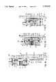
- FIG. 1is a perspective view of a preferred embodiment of a transducer of the invention
- FIG. 2is a front view of the transducer shown in FIG. 1;
- FIG. 3is a front view of the reusable component of FIG. 1;
- FIG. 4is a cross-sectional view taken along lines 4--4 of FIG. 1;
- FIG. 5is an exploded, cross-sectional view taken along lines 5--5 of FIG. 2;
- FIG. 6is a rear, partially cut-away view of the disposable component of FIG. 1;
- FIGS. 7A-7Care diagrammatic side views, taken along lines 7A--7A of FIG. 2, to illustrate interaction of the dome wings and reusable component channels;
- FIG. 8is an exploded diagrammatic view of a pole mount arrangement for a plurality of the transducers of FIG. 1;
- FIG. 9is a front diagrammatic view of a plurality of the transducers of FIG. 1 in pole-mounted position;
- FIG. 10is a front perspective view of an alternative embodiment of a transducer in accordance with the principles of the present invention.
- FIG. 11is a rear perspective view of the support plate of the transducer of FIG. 10;
- FIG. 12is a partial, perspective view of a second alternative embodiment of a transducer in accordance with the principles of the present invention.
- FIG. 13is a partial, perspective view of a third alternative embodiment of a transducer in accordance with the principles of the present invention.
- FIG. 14is a partial, perspective view of a fourth alternative embodiment of a transducer in accordance with the principles of the present invention.
- Transducer 10includes two major components, one being a reusable sensor component 100 of the invention and the other being a disposable fluid dome component 200 of the invention, removably and slidably mounted to reusable component 100.
- reusable component 100is a pole-mountable supporting plate or housing with a reusable pressure sensor system built into it as will be described.
- component 100may be seen as having an opaque plastic support 102 in the form of a plate.
- Plate 102has generally planar left edge 104, generally planar right edge 106, and generally planar top and bottom edges 108,110 to define a generally rectangular shape to plate 102.
- Extending between edges 104,106,108,110is a generally planar front face 112.
- An aperture 122At the upper end of chamber 114 through face 112 is an aperture 122. Permanently mounted over aperture 122 is an elastomeric reusable diaphragm 124 such as of molded polyurethane.
- Additional gel 126is inserted in liquid state into chamber 114 between diaphragm 124 and chimney 116 via fill port 128 to bring diaphragm 124 into pressure communication, via gels 126 and 117, with sensor 118.
- Port 128is sealed such as by insertion of a tightly-fitting ball or screw or the like (not shown) to thus slightly distend diaphragm 124 and gel 126 is cured.
- the edge 130 of diaphragm 124defines a cylindrical collar that is fitted into annular groove 132 in face 112 about aperture 122 to hold diaphragm 124 to support 102 with the front face or surface 134 of reusable diaphragm 124 exposed in, or bulging just slightly above, the plane of front face 112.
- a plurality of conductors 140interconnect calibration test switch 142 and connector 144 to PC board substrate 120 circuitry and sensor 118, all behind face 112 of plate 102.
- Switch 142is fitted within open-bottom well 145 formed into face 112 with switch button 146 being accessible at aperture 148 through plate face 112 in the lower left comer thereof as seen from the front (FIG. 3).
- Conductors 140could be separate wires or ribbon cable and/or conductive traces (not shown) on a switch-supporting PC board 149.
- Placed over aperture 148is a compliant, polycarbonate membrane 150 to protect switch 142 and to allow actuation thereof such as by gripping of reusable component 100 between the thumb and forefinger (not shown) in the area of membrane 150 and compressing same.
- Membrane 150is adhesively held along its perimeter to the edge of well 145 defined at aperture 148. Actuation of switch 142 provides a calibration test as generally described in U.S. Pat. No. 4,760,730, the disclosure of which is incorporated herein by reference, but as a directly integral part of the reusable component, rather than as a separate component.
- connector 144is provided at the bottom right of component 100 as seen from the front (FIGS. 2 and 3).
- Connector 144may have a cylindrical plastic shell 152 with female pin-receiving connectors 154 therein and housed in a bulbously protruded area 156 of component 100.
- Connector 144is accessible through connector port 158 in bottom edge 110.
- Connector 144may form part of a two-connector set as shown in U.S. Pat. No. 5,167,522.
- An opaque plastic back plate 157may be secured, such as by adhesive (not shown), over the back side of plate 102 to enclose the above-mentioned components, with a tongue T and groove G arrangement (see FIG.
- plate 157may be press-fit to plate 102 by interaction of the tongue T and groove G and pins P and bosses B shown in FIG. 4. Also, the housing defined by plate 102 and back 157 may be vented, such as via a small through-hole or path (not shown) formed therein. A filter member (also not shown) may be included with the through-hole or path. Additionally, plate 157 is adapted to be mountable to a pole and thus includes structure to connect to a pole-mount as will be discussed, thereby eliminating the extra part and manipulation required by the operator to mount the reusable sensor portion to the support plate.
- plate 102is provided with channel members which, in the preferred embodiment shown in FIGS. 1-9, are defined by a pair of channels 160,162 disposed to opposite left and right sides of reusable diaphragm 124 as seen from the front (FIG. 3).
- Each channel 160,162is defined behind a respective outer front wall 164,166 associated with plate 102.
- outer front walls 164,166are generally parallel to, but spaced from, front face 112 and held thereto by interconnecting side walls 170,172, respectively, to thus define generally linear and parallel paths or channels 160,162 between front face 112 and the underside 174,176 of each respective outer front wall 164,166.
- the lateral extent of each channel 160,162is further defined by side walls 170,172, respectively.
- the underside 174 or 176 of outer front wall 164 or 166may be slightly angled with a draft (such as for molding) as it progresses from near the top edge 108 of plate 102 towards the bottom edge 110 thereof (FIG. 5). The draft narrows somewhat the width of the channel 160 or 162 in the direction of insertion travel of the dome 200.
- camming structureis provided at the terminal or bottom end 178 of the channels 160,162.
- the camming structure in the preferred embodiment shownis provided by camming ramp 180° comprised of a 45° ramp 182 and a trailing step 184 to define a generally precise channel width W c thereat (see FIG. 7A).
- the top edge 186 of each wall 164,166is exposed.
- the bottom end 178 of each channel 160 or 162may be closed off (not shown) but is advantageously left open as shown so that debris does not accumulate in the channels.
- outer surface 190 of right side channel outer front wall 166includes a depression such as tab-receiving slot 192 formed therein (over side wall 172). Slot 192 extends into alleyway 194 also formed in outer surface 190 (over channel 162) which in turn ends adjacent chamfer 196 of outer front wall 166 all for purposes to be described hereinafter.
- Outer surface 190is otherwise generally planar and parallel to front face 112.
- Outer surface 197 of left side, outer front wall 164is similarly planar and parallel to front face 112.
- support plate 102could be made of more than one piece or element joined together to provide the structural and functional relationship of the elements described above.
- disposable dome 200is of clear or translucent plastic and may be seen as having a central body portion 202 defined between left and right edges 204,206 and top and bottom edges 208,210 to define a generally rectangular shape to central body portion 202.
- a fluid path well 212which communicates through an inlet port 214 extending up out of the front of well 212 and accessible along bottom edge 210 and outlet pipe 216 extending up out of the front of well 212 and beyond top edge 208.
- Inlet and outlet 214 and 216cooperate to extend fluid path 212 through disposable dome 200.
- Fluid path 212is accessible through a large aperture 218 along the back side 220 of central portion 202.
- Well 212 and aperture 218are defined by a cylindrical wall 221 in central portion 202 with cavities 222 defined between wall 221 and edges 204,206,208,210.
- cavities 222could be filled with plastic.
- back side 220 of dome 200functions to define a flat or plate-like surface to dome 200 to match up to planar face 112 of plate 102.
- Diaphragm 224Extending across aperture 218 along bottom side 220 is an elastomeric diaphragm 224 permanently affixed to central portion 202 and providing a pressure transmitting, fluid impervious wall to seal the fluid path within dome 200.
- Diaphragm 224could be a molded polyurethane, like diaphragm 124 with a collar (not shown) mounted within an annular recess or groove (also not shown) about aperture 218.
- diaphragm 224could be a sheet of urethane film material, the peripheral edge of which is either adhesively or thermally bonded to the edge of aperture 218, or is held into a groove (not shown) about aperture 218 such as by a compression ring (also not shown).
- the domeis provided with a pair of edges that mate with the channel members of the reusable component.
- extending outwardly from opposite left and right sides (as viewed in FIGS. 2 and 4) of central portion 202 (from edges 204 and 206, respectively) and to either side of diaphragm 224are generally linear and parallel left and right mounting wings 230,232 situated to be matingly received within channels 160,162 of reusable plate 102 such as to place disposable diaphragm 224 into confronting relationship with reusable diaphragm 124.
- Bottom end 234 of each wing 230,232is chamfered as at 235 (see FIG. 7A) for purposes to be described hereinafter.
- Bottom end 234 just above chamfer 235has a generally precise thickness or width, which in combination with diaphragms 224 and 124, is closely equal to channel width W c , so as to hold the diaphragms in proper pressure communicating relationship.
- Further camming structureis defined at top or distal end 236 of each wing.
- the further camming structureis provided by camming ramp 240 which, like the camming ramp 180 within channels 160 and 162, is comprised of a 45° ramp 242 and a trailing step 244 to define a precise width W w of wing 230 or 232 in the area of trailing step 244.
- the thickness or width of the channels 160,162 at their openings near the top edge 108 of plate 102cooperate with diaphragms 224 and 124 to closely equal width W w so as to, in addition or alternatively to the holding ability of bottom end 234 and width W c , hold the diaphragms in proper pressure communicating relationship.
- Camming ramp 180 and camming ramp 240are situated on respective ones of the reusable component 100 and disposable dome 200 so as to engage their respective counterpart structures near the tailing end of the travel of dome 200 as the wings 230,232 are slidably received into the channels 160,162 of the reusable component 100.
- the dome 200travels generally linearly in a direction generally parallel to the reusable diaphragm 124 into reusable component 100, there may be a slight space (or just loose, sliding contact) between the diaphragms 124 and 224 so as not to harmfully abrade at least diaphragm 124.
- a closing wall 246may be provided at distal or top end 236 of each wing 230,232 which closing wall 246 will abut into top edge 186 of outer front walls 164 or 166.
- a second set of wings 250,252may be provided. Wings 250,252 also extend from edges 204 and 206 but spaced above respective ones of mounting wings 230,232 to define wall-receiving spaces 254,256 (FIGS. 4 and 7). As is thus apparent, wing pairs 230,250 and 232,252 cause spaces 254,256 to function as attachment structure channels of the dome to receive respective ones of outer walls 164 and 166 which function as wing-like attachment structure of the reusable component as dome 200 is slidingly received into reusable component 100.
- Second wings 250,252extend generally outwardly so as to substantially overlie outer walls 164 and 166 to provide the aesthetic appearance of a single unit when components 200 and 100 are mounted together as shown in FIG. 1. Additionally, wings 250,252 may also provide a barrier to debris from entering channels 160,162 when dome 200 is mounted to plate 102.
- lateral edges 260,262 of second wings 250,252, respectively,may be indented as at 264 and 265, respectively, to provide finger and thumb gripping areas for the user (not shown) to grip dome 200 to mount and dismount same from reusable component 100.
- Finger-gripping portions 264, 265may be textured (such as by grooving, serrating or knurling) to facilitate such manipulation by the user.
- indented finger-gripping portion 265 of right side second wing 252may actually be provided by resilient locking or flexing paddle 270 having an indented shape and a textured surface to simulate indented portion 264 of left side second wing 250.
- Locking paddle 270Supported at a terminal end 272 of paddle 270 is a locking tab 274 such that tab 274 defines a projection resiliently attached to dome 200 and spaced above and depending towards wing 232.
- Locking paddle 270extends from a hinging area 276 nearer to the bottom end 278 of wing 252 such that by flexing action of locking paddle 270, locking tab 274 is movable towards central portion 202 near to the top end 280 of wing 252.
- dome 200As dome 200 is slidably received into reusable component 100, locking tab 274 may bear against chamfer 196 (FIG. 3) of outer wall 166 to thereby flex paddle 270 leftwardly. As dome 200 moves further in its travel, tab 274 passes onto alleyway 194 and then, at the end of the travel of dome 200, snaps rightwardly back out into slot 192 (with a clicking sound) to lock dome 200 into position on plate 102 with diaphragms 224 and 124 in confronting, pressure transmitting relationship (FIG. 7C).
- dome 200the user (not shown) may grip dome 200 with the thumb (not shown) in indented portion 264 and the forefinger (not shown) against locking paddle 270 compressing same so that locking tab 274 comes away from tab-receiving slot 192, and then sliding upwardly towards the top edge 108 of plate 102 to withdraw dome 200 therefrom.
- Dome 200may be provided with a fast-flush device 290 coupled to inlet port 214 (such as the fast flush device shown in U.S. Pat. No. 5,171,230) and a stopcock 292 coupled to outlet pipe 216.
- Flush device 290may then be connected by tubing 294 to a source of saline (not shown) and stopcock 292 may be connected by further tubing 296 to a catheter 298 (FIG. 2) to be placed within the patient's circulatory system (not shown) to thus monitor the pressure thereof as in the case of sensor 102 in FIG. 7 of U.S. Pat. No. 5,221,271, the disclosure of which is incorporated herein by reference.
- outer front wallsmay be coplanar with front face 112 with appropriate adjustment in the elevation of either diaphragm 124 or mounting wings 230,232, by way of example.
- slot 192is shown on support 102 and locking tab 274 on dome 200, they could be reversed.
- dome 200is just about to be mounted to plate 102 with wing 232 just beginning to enter channel 162 in a direction along the downwardly-directed arrow A.
- dome wing 232is coming into channel 162 from the direction of top edge 108 of plate 102.
- Top end 186 of outer front wall 166may be impacted by chamfered wall 235 at the proximal end of wing 232 to help force wing 232 into the space or channel 162 defined behind outer front wall 166.
- second wing 252is spaced above and away from top surface 190 of front wall 166.
- dome 200is continued in its downward progression towards bottom wall 110, as in FIG. 7B, most of the length of wing 232 passes into channel 162 and wing 252 passes over front 190 of front wall 166.
- this progression of travelit may be seen that there may be a slight space or at least a loose or sliding contact (indicated by the letter S) between diaphragms 224 and 124 so as to avoid damaging or chafing the diaphragms, and especially diaphragm 124 which is intended to be reusable with several of domes 200.
- chamfer 235hits against ramp 182 of camming ramp 180 to start to drive the proximal end of wing 232 towards face 112 and diaphragm 124.
- camming ramp 242impacts against top edge 186 to also drive the distal end of wing 232 towards face 112 and diaphragm 124 in which event the spacing S between diaphragms 224 and 124 begins to decrease (or the loose contact begins to tighten up). Also, tab 274 impinges wall chamfer 196 (FIG. 3) and flexes paddle 270 inwardly so as to allow tab 274 to travel into alleyway 194.
- wing 232In the end of the travel of dome 200 into reusable component 100 in FIG. 7C, the proximal end of wing 232 is situated below and against trailing end 184 and the top end 186 of outer wall 166 is situated above and against trailing end 244 of wing camming ramp 240 such that wing 232 has been driven towards plate face 112 and diaphragms 224 and 124 have been driven into abutting relationship to provide the desired pressure communicating relationship therebetween. Also, in this terminal end of the travel, second wing 252 is positioned so as to substantially completely overlie top surface 190 of front wall 166, and paddle 270 has gone back towards its original position with tab 274 locked into slot 192. The same arrangement of travel as shown in FIGS. 7A-7C occurs simultaneously between wing 230 and channel 160.
- dome 200is slidably mounted to reusable component 100 as above described and appropriate tubing 294,296 and catheter 298 are employed to couple fluid path 212 of transducer 10 to a patient and connector 144 utilized to couple signals representing the patient's blood pressure, for example, with a monitor in an otherwise conventional manner such as FIG. 7 of the aforementioned U.S. Pat. No, 5,221,271.
- dome 200may be simply removed by depressing locking paddle 270 and sliding dome 200 out of channels 160,162 of reusable component 100 and the dome 200 disposed of (with or without tubing).
- Either new tubingmay be provided, or the old tubing used, with a new dome 200 as appropriate, depending upon the patient's situation, and new dome 200 slidably remounted to reusable component 100 as previously described. In many situations, it may be desirable to monitor more than one pressure. In this event, multiple transducers 10 may be utilized as will now be described with reference to FIG. 8.
- Back plate 157 of each reusable componentmay be provided with a mounting structure 300 to mount component 100 to an intravenous pole or other support.
- structure 300is mounted to a support frame 302 which, in turn, is mounted to a pole-mount clamp 304 secured to a pole 306.
- the mounting frame 302includes a plurality of receptacles 308 to receive the respective support structure 300 of a plurality of reusable components 100 which are then locked in place by actuation of the locking handle 310 on frame 302.
- Frame 302also includes an identical mounting structure 300 receivable in an identical receptacle 308 and held thereto by actuation of handle 310 on the proximal end 312 of pole mount clamp 304.
- Clamp 304is held to pole 306 in conventional manner such as by interaction of yoke 314 and screw 316 about pole 306.
- one reusable component 100may be mounted directly to the pole mount clamp 304 and frame 302 dispensed with.
- each plate 102could be provided as modular interconnecting plates as shown in aforementioned U.S. Pat. No. 5,417,395.
- transducer 10includes as part of the reusable component, structure by which to be mountable to a pole without the need for an additional support plate as was typical of the prior art.
- transducer 400includes rigid mounting plate 401 having a generally planer front face 402. Extending along the length of right side edge 404 of plate 400 is a rib 406 receivable in slot 408 along the left side edge 410 of another identical transducer 400 or mounting plate 401 and locked thereto by action of pivoting arms 412 pivotally mounted to plate 401 all as described in previously mentioned application Ser. No. 08/407,903 and U.S. Pat. No.
- shelf 413by which plate 401 is mountable to the intravenous pole 306 (see FIG. 8) or other external structure by way of well known clamping mechanisms (such as pole-clamping mechanism 85 in the aforesaid application and patent).
- shelf 413could be replaced with mounting structure 300 to be pole-mountable as described above.
- Rigid plate 401has an aperture 414 formed therethrough with reusable diaphragm 416 affixed to plate face 402 across aperture 414.
- a transducer sensor 418(FIG. 11) is secured to plate 401 behind aperture 414 and placed into pressure communication with diaphragm 416, such as via a gel-filled recess, to fully perform the function of a reusable transducer component.
- Wires 420extend from sensor 418 to be coupled to a monitor (not shown).
- Sensor 418may alternatively have electrical connectors extending therefrom for releasable attachment to a cable coupled to the monitor.
- the construction of sensor 418 and diaphragm 416 and the reusable transducer portionsmay be as described above in connection with FIGS. 1-9 and/or as disclosed in U.S. Pat. No. 4,920,972, the disclosure of which is incorporated herein by reference, and previously mentioned U.S. Pat. No. 5,417,395.
- Fluid dome 424includes an inlet 26 and an outlet 28 in fluid communication with a path extending through dome 424 and sealed off by diaphragm 422 as in the case of dome 200 above-described.
- attachment structureis provided on both plate 401 and dome 424.
- the attachment structure of plate 401is provided by channel members defined as a pair of slots 430 parallel to right and left side edges 404 and 410 of rigid plate 401 and extending through face 402 on opposite sides of aperture 414 and diaphragm 416. Slots 430 are sized and positioned to receive locking arms 434 pivotally connected by pivot members 436 to fluid dome 424. Arms 434 have inwardly facing hooks 438 thereon.
- hooks 438ride over inner edges 440 of slots 430, and when disposable dome diaphragm 422 is in confronting, pressure communicating engagement with the reusable portion diaphragm 416, hooks 438 emerge through rigid plate 401 and locking arms 434 resume their undeformed shape thereby securely locking disposable dome 424 to mounting plate 401.
- proximal ends 442 of locking arms 434are inwardly depressed to pivot the distal ends 438 outwardly, thereby disengaging hooks 438 from the slot inner edges 440 whereby dome 424 may be pulled free of the mounting plate 400.
- locking arms 434could be extended as at 434' to substantially lengthen slots 430.
- pivot members 436are replaced with connecting plate 436', although use of dome 424 in FIG. 12 is the same as in FIGS. 10 and 11.
- a "ski-boot" foot and latching arm structuremay be used as shown in FIG. 13. To this end, plate 401 and reusable portion diaphragm 416 continue to remain unchanged from that described above.
- disposable fluid dome 424is replaced with an outwardly facing L-shaped foot 450 connected to one side of connecting plate 436' and extending forwardly therefrom, and an extended length latch member arm 434" on the other side of the connecting plate 436', which is the same as that described above for arm 434' but with a lever arm 452 attached thereto for a purpose to be described.
- dome 424is pivoted onto its side so that the free end 454 of foot 450 may be inserted into one of slots 430. Fluid dome 424 is then pivoted towards plate face 402 until latching member 434" locks into the other slot 430 thereby placing the respective diaphragms in confronting pressure communicating engagement.
- lever arm 452is lifted to disengage latching arm 434" from mounting plate 401 and fluid dome 424 is pivoted, whereby foot 450 may be removed from slot 430 and fluid dome 424 lifted from mounting plate 401.
- FIG. 14another embodiment of the transducer 400 of FIG. 10 is shown utilizing the simplified wing/channel arrangement of the transducer 10 of FIG. 1.
- the channel membersare defined in plate 401 by L-shaped walls 460 extending along slots 430 and an outer front wall 462 attached to each wall 460 to define a receptacle or channel 464 therebehind and communicating to each slot 430.
- the fluid dome 424is modified such that the edges define wings 470 extending outwardly of dome 424 and in the same plane to be slidingly received into the receptacles 464 to thus hold the respective diaphragms into confronting engagement.
- Wings 470may be part of a plate 472 formed along the bottom or back side of dome 424.
- a medical pressure transducerin which the reusable portion and support plate are combined to eliminate a part and its extra manipulation. Further, such a transducer is provided in which the dome and reusable component easily and simply mate together, such as by relative sliding action in a preferred embodiment.
- Featuresare provided to enhance the pressure transmitting relationship between the diaphragms and to facilitate operator use of the transducer.
- the inventionin its broader aspects is not, however, limited to the specific details, representative apparatus and methods and illustrative examples shown and described.
Landscapes
- Engineering & Computer Science (AREA)
- General Engineering & Computer Science (AREA)
- Health & Medical Sciences (AREA)
- Mechanical Engineering (AREA)
- Hematology (AREA)
- General Health & Medical Sciences (AREA)
- Biomedical Technology (AREA)
- Heart & Thoracic Surgery (AREA)
- Vascular Medicine (AREA)
- Life Sciences & Earth Sciences (AREA)
- Animal Behavior & Ethology (AREA)
- Anesthesiology (AREA)
- Public Health (AREA)
- Veterinary Medicine (AREA)
- Physics & Mathematics (AREA)
- General Physics & Mathematics (AREA)
- External Artificial Organs (AREA)
- Measuring Fluid Pressure (AREA)
- Ultra Sonic Daignosis Equipment (AREA)
Abstract
Description
Claims (92)
Priority Applications (3)
| Application Number | Priority Date | Filing Date | Title |
|---|---|---|---|
| US08/496,080US5752918A (en) | 1993-06-30 | 1995-06-28 | Modular medical pressure transducer |
| US08/759,303US5868678A (en) | 1993-06-30 | 1996-12-02 | Two-part medical pressure transducer with diaphragm stand-offs |
| US08/837,919US5848971A (en) | 1993-06-30 | 1997-04-11 | Modular medical pressure transducer |
Applications Claiming Priority (4)
| Application Number | Priority Date | Filing Date | Title |
|---|---|---|---|
| US08/085,352US5417395A (en) | 1993-06-30 | 1993-06-30 | Modular interconnecting component support plate |
| US40790395A | 1995-03-21 | 1995-03-21 | |
| CA002224428ACA2224428C (en) | 1993-06-30 | 1995-06-28 | Medical pressure transducer with sliding components |
| US08/496,080US5752918A (en) | 1993-06-30 | 1995-06-28 | Modular medical pressure transducer |
Related Parent Applications (1)
| Application Number | Title | Priority Date | Filing Date |
|---|---|---|---|
| US40790395AContinuation-In-Part | 1993-06-30 | 1995-03-21 |
Related Child Applications (2)
| Application Number | Title | Priority Date | Filing Date |
|---|---|---|---|
| US08/759,303Continuation-In-PartUS5868678A (en) | 1993-06-30 | 1996-12-02 | Two-part medical pressure transducer with diaphragm stand-offs |
| US08/837,919DivisionUS5848971A (en) | 1993-06-30 | 1997-04-11 | Modular medical pressure transducer |
Publications (1)
| Publication Number | Publication Date |
|---|---|
| US5752918Atrue US5752918A (en) | 1998-05-19 |
Family
ID=27170569
Family Applications (2)
| Application Number | Title | Priority Date | Filing Date |
|---|---|---|---|
| US08/496,080Expired - LifetimeUS5752918A (en) | 1993-06-30 | 1995-06-28 | Modular medical pressure transducer |
| US08/837,919Expired - LifetimeUS5848971A (en) | 1993-06-30 | 1997-04-11 | Modular medical pressure transducer |
Family Applications After (1)
| Application Number | Title | Priority Date | Filing Date |
|---|---|---|---|
| US08/837,919Expired - LifetimeUS5848971A (en) | 1993-06-30 | 1997-04-11 | Modular medical pressure transducer |
Country Status (4)
| Country | Link |
|---|---|
| US (2) | US5752918A (en) |
| EP (1) | EP0835145B1 (en) |
| CA (1) | CA2224428C (en) |
| WO (1) | WO1997001364A1 (en) |
Cited By (65)
| Publication number | Priority date | Publication date | Assignee | Title |
|---|---|---|---|---|
| US5983726A (en)* | 1997-12-19 | 1999-11-16 | Wika Alexander Wiegand Gmbh & Co. | Process for the production of an assembly of a membrane pressure sensor and a membrane pressure sensor |
| US5993395A (en)* | 1996-04-18 | 1999-11-30 | Sunscope International Inc. | Pressure transducer apparatus with disposable dome |
| USD424192S (en)* | 1997-08-18 | 2000-05-02 | Sunscope International, Inc. | Medical pressure transducer for measuring blood pressure |
| US6117086A (en)* | 1996-04-18 | 2000-09-12 | Sunscope International, Inc. | Pressure transducer apparatus with disposable dome |
| US6214634B1 (en)* | 1997-05-28 | 2001-04-10 | Motorola, Inc. | Sensor device and method of forming a sensor device |
| EP1136088A1 (en)* | 1995-06-28 | 2001-09-26 | Medex, Inc. | Medical pressure transducer with sliding components |
| US6475750B1 (en) | 1999-05-11 | 2002-11-05 | M-Biotech, Inc. | Glucose biosensor |
| US6514689B2 (en) | 1999-05-11 | 2003-02-04 | M-Biotech, Inc. | Hydrogel biosensor |
| US6568241B2 (en) | 1999-01-11 | 2003-05-27 | Becton Dickinson And Company | Isolated calibration adapter for sterile pressure transducer |
| WO2003001993A3 (en)* | 2001-06-26 | 2003-08-21 | Thermometrics Lp | Reusable fluid pressure transducer monitoring apparatus |
| US20040074281A1 (en)* | 2002-10-16 | 2004-04-22 | Lobdell Donn D. | Testing of pressure sensor in surgical cassette |
| US20040261534A1 (en)* | 2003-06-30 | 2004-12-30 | Mikhail Boukhny | Noninvasive pressure sensing assembly |
| US20050205142A1 (en)* | 2001-08-21 | 2005-09-22 | Boston Scientific Scimed, Inc. | Pressure transducer protection valve |
| US6955073B2 (en) | 2002-10-16 | 2005-10-18 | Alcon, Inc. | Pressure sensing in surgical console |
| US7021148B2 (en) | 2002-04-30 | 2006-04-04 | Baxter International Inc. | Apparatus and method for sealing pressure sensor membranes |
| US20070083088A1 (en)* | 2003-09-12 | 2007-04-12 | Laborie Medical Technologies Inc. | Apparatus and method for medical measurement |
| US20070109117A1 (en)* | 2005-11-14 | 2007-05-17 | Edwards Lifesciences Corporation | Wireless communication protocol for a medical sensor system |
| US20070112274A1 (en)* | 2005-11-14 | 2007-05-17 | Edwards Lifesciences Corporation | Wireless communication system for pressure monitoring |
| US20070179400A1 (en)* | 2002-07-12 | 2007-08-02 | Laborie Medical Technologies, Inc. | Apparatus and Method for Medical Measurement |
| US20070293786A1 (en)* | 2006-06-14 | 2007-12-20 | William Wekell | Reusable invasive fluid pressure monitoring apparatus and method |
| USD559671S1 (en) | 2007-06-08 | 2008-01-15 | Smiths Medical Asd, Inc. | Mounting clip |
| US20080302932A1 (en)* | 2007-06-08 | 2008-12-11 | Smiths Medical Asd, Inc. | Mounting Clip for Fluid Reservoir |
| US20090157040A1 (en)* | 2007-12-17 | 2009-06-18 | Hospira, Inc. | Differential pressure based flow sensor assembly for medication delivery monitoring and method of using the same |
| US20090288497A1 (en)* | 2008-05-23 | 2009-11-26 | Hospira, Inc. | Cassette for differential pressure based medication delivery flow sensor assembly for medication delivery monitoring and method of making the same |
| US20100057058A1 (en)* | 2008-09-02 | 2010-03-04 | Hospira, Inc. | Cassette for use in a medication delivery flow sensor assembly and method of making the same |
| US20100114027A1 (en)* | 2008-11-05 | 2010-05-06 | Hospira, Inc. | Fluid medication delivery systems for delivery monitoring of secondary medications |
| US20100114063A1 (en)* | 2008-11-04 | 2010-05-06 | Angiodynamics, Inc. | Catheter injection monitoring device |
| US20100198155A1 (en)* | 2009-01-30 | 2010-08-05 | Hospira, Inc. | Cassette for differential pressure based medication delivery flow sensor assembly for medication delivery monitoring and method of making the same |
| US20100280486A1 (en)* | 2009-04-29 | 2010-11-04 | Hospira, Inc. | System and method for delivering and monitoring medication |
| US20110214504A1 (en)* | 2006-02-17 | 2011-09-08 | Honeywell International Inc. | Disposable pressure sensor systems and packages therefor |
| US8760637B2 (en) | 2010-08-30 | 2014-06-24 | Alcon Research, Ltd. | Optical sensing system including electronically switched optical magnification |
| US20160106906A1 (en)* | 2013-03-28 | 2016-04-21 | Quanta Fluid Solutions Ltd | Blood pump |
| US20170304116A1 (en)* | 2012-03-17 | 2017-10-26 | Abbott Medical Optics Inc. | Surgical cassette |
| US9956377B2 (en) | 2002-09-20 | 2018-05-01 | Angiodynamics, Inc. | Method and apparatus for intra-aortic substance delivery to a branch vessel |
| US10022498B2 (en) | 2011-12-16 | 2018-07-17 | Icu Medical, Inc. | System for monitoring and delivering medication to a patient and method of using the same to minimize the risks associated with automated therapy |
| US10143795B2 (en) | 2014-08-18 | 2018-12-04 | Icu Medical, Inc. | Intravenous pole integrated power, control, and communication system and method for an infusion pump |
| US10166328B2 (en) | 2013-05-29 | 2019-01-01 | Icu Medical, Inc. | Infusion system which utilizes one or more sensors and additional information to make an air determination regarding the infusion system |
| US10279112B2 (en) | 2012-09-24 | 2019-05-07 | Angiodynamics, Inc. | Power injector device and method of use |
| US10342701B2 (en) | 2007-08-13 | 2019-07-09 | Johnson & Johnson Surgical Vision, Inc. | Systems and methods for phacoemulsification with vacuum based pumps |
| US10342917B2 (en) | 2014-02-28 | 2019-07-09 | Icu Medical, Inc. | Infusion system and method which utilizes dual wavelength optical air-in-line detection |
| US10430761B2 (en) | 2011-08-19 | 2019-10-01 | Icu Medical, Inc. | Systems and methods for a graphical interface including a graphical representation of medical data |
| US10441461B2 (en) | 2006-11-09 | 2019-10-15 | Johnson & Johnson Surgical Vision, Inc. | Critical alignment of fluidics cassettes |
| US10463788B2 (en) | 2012-07-31 | 2019-11-05 | Icu Medical, Inc. | Patient care system for critical medications |
| US10578474B2 (en) | 2012-03-30 | 2020-03-03 | Icu Medical, Inc. | Air detection system and method for detecting air in a pump of an infusion system |
| US10596316B2 (en) | 2013-05-29 | 2020-03-24 | Icu Medical, Inc. | Infusion system and method of use which prevents over-saturation of an analog-to-digital converter |
| US10635784B2 (en) | 2007-12-18 | 2020-04-28 | Icu Medical, Inc. | User interface improvements for medical devices |
| US10656894B2 (en) | 2017-12-27 | 2020-05-19 | Icu Medical, Inc. | Synchronized display of screen content on networked devices |
| US10850024B2 (en) | 2015-03-02 | 2020-12-01 | Icu Medical, Inc. | Infusion system, device, and method having advanced infusion features |
| US10874793B2 (en) | 2013-05-24 | 2020-12-29 | Icu Medical, Inc. | Multi-sensor infusion system for detecting air or an occlusion in the infusion system |
| US10918787B2 (en) | 2015-05-26 | 2021-02-16 | Icu Medical, Inc. | Disposable infusion fluid delivery device for programmable large volume drug delivery |
| US10959881B2 (en) | 2006-11-09 | 2021-03-30 | Johnson & Johnson Surgical Vision, Inc. | Fluidics cassette for ocular surgical system |
| US11135360B1 (en) | 2020-12-07 | 2021-10-05 | Icu Medical, Inc. | Concurrent infusion with common line auto flush |
| USD939079S1 (en) | 2019-08-22 | 2021-12-21 | Icu Medical, Inc. | Infusion pump |
| US11213619B2 (en) | 2013-11-11 | 2022-01-04 | Icu Medical, Inc. | Thermal management system and method for medical devices |
| US11246985B2 (en) | 2016-05-13 | 2022-02-15 | Icu Medical, Inc. | Infusion pump system and method with common line auto flush |
| US11278671B2 (en) | 2019-12-04 | 2022-03-22 | Icu Medical, Inc. | Infusion pump with safety sequence keypad |
| US11324888B2 (en) | 2016-06-10 | 2022-05-10 | Icu Medical, Inc. | Acoustic flow sensor for continuous medication flow measurements and feedback control of infusion |
| US11337855B2 (en) | 2006-11-09 | 2022-05-24 | Johnson & Johnson Surgical Vision, Inc. | Holding tank devices, systems, and methods for surgical fluidics cassette |
| US11344673B2 (en) | 2014-05-29 | 2022-05-31 | Icu Medical, Inc. | Infusion system and pump with configurable closed loop delivery rate catch-up |
| US11344668B2 (en) | 2014-12-19 | 2022-05-31 | Icu Medical, Inc. | Infusion system with concurrent TPN/insulin infusion |
| US11369739B2 (en) | 2013-01-21 | 2022-06-28 | Medline Industries, Lp | Method to provide injection system parameters for injecting fluid into patient |
| US11883361B2 (en) | 2020-07-21 | 2024-01-30 | Icu Medical, Inc. | Fluid transfer devices and methods of use |
| USD1052728S1 (en) | 2021-11-12 | 2024-11-26 | Icu Medical, Inc. | Medical fluid infusion pump |
| US12350233B2 (en) | 2021-12-10 | 2025-07-08 | Icu Medical, Inc. | Medical fluid compounding systems with coordinated flow control |
| USD1091564S1 (en) | 2021-10-13 | 2025-09-02 | Icu Medical, Inc. | Display screen or portion thereof with graphical user interface for a medical device |
Families Citing this family (8)
| Publication number | Priority date | Publication date | Assignee | Title |
|---|---|---|---|---|
| US5868678A (en)* | 1993-06-30 | 1999-02-09 | Medex, Inc. | Two-part medical pressure transducer with diaphragm stand-offs |
| US5937950A (en)* | 1996-12-02 | 1999-08-17 | Medex, Inc. | Cable system for medical equipment |
| DE102006008752B4 (en)* | 2006-02-24 | 2012-11-29 | Smiths Medical Deutschland Gmbh | A method of manufacturing a component of a fluid pressure measuring unit, method of manufacturing a fluid pressure measuring unit, component for use in a fluid pressure measuring unit and fluid pressure measuring unit |
| US9375180B2 (en) | 2012-04-29 | 2016-06-28 | Acist Medical Systems, Inc. | Universal pressure transducer mounting device |
| CA2938161A1 (en)* | 2014-02-01 | 2015-08-06 | Ezmems Ltd. | Chip device for monitoring and regulating fluid flow, and methods of manufacture thereof |
| WO2018025264A1 (en)* | 2016-08-03 | 2018-02-08 | Ezmems Ltd. | Fluidic microelectromechanical sensors/devices and fabrication methods thereof |
| US11033898B2 (en) | 2014-02-01 | 2021-06-15 | Ezmems Ltd. | Fluidic microelectromechanical sensors/devices and fabrication methods thereof |
| CN111779957B (en)* | 2020-07-13 | 2021-11-05 | 高心成 | A angular transducer installing support for industrial grade mechanical equipment |
Citations (132)
| Publication number | Priority date | Publication date | Assignee | Title |
|---|---|---|---|---|
| US33360A (en)* | 1861-09-24 | Improved canteen | ||
| US33518A (en)* | 1861-10-22 | Improved feathering paddle-wheel | ||
| US190651A (en)* | 1877-05-08 | Improvement in couplings for lead pipes | ||
| US344312A (en)* | 1886-06-22 | Georges guillemot | ||
| US944312A (en)* | 1909-02-19 | 1909-12-28 | Martin H Brede | Tool-rack. |
| US1286819A (en)* | 1918-06-07 | 1918-12-03 | James R Snyder | Flexible pipe-joint. |
| US1325902A (en)* | 1919-12-23 | Abraham sjovxck | ||
| US2169371A (en)* | 1936-09-01 | 1939-08-15 | Payne Mathew | Syringe |
| US2371433A (en)* | 1944-04-07 | 1945-03-13 | William M Davis | Tool supporting rack |
| FR1049697A (en) | 1952-01-21 | 1953-12-31 | Holder for tools and other objects | |
| US2667184A (en)* | 1952-02-05 | 1954-01-26 | Alltools Ltd | Hydrostatic coupling |
| US2762595A (en)* | 1951-06-05 | 1956-09-11 | Malleable Iron Fittings Co | Interlocked bracket and fastener |
| US3081023A (en)* | 1961-11-30 | 1963-03-12 | Robert C Taylor | Rural mailbox |
| US3249105A (en)* | 1963-04-19 | 1966-05-03 | American Optical Corp | Devices for measuring blood pressure |
| US3269550A (en)* | 1965-06-04 | 1966-08-30 | Marcus William | Rack |
| FR1467702A (en) | 1966-02-09 | 1967-01-27 | perforated plastic elements for the construction of walls, mainly for buildings and decoration | |
| US3429450A (en)* | 1966-12-08 | 1969-02-25 | June J Lambert | Storage rack |
| US3452954A (en)* | 1967-08-04 | 1969-07-01 | Lambert A Lucietto | Bracket for mounting on apertured panel |
| US3499434A (en)* | 1965-04-12 | 1970-03-10 | Hellige & Co Gmbh F | Device for measuring and/or recording intracardiac pressure and sounds |
| US3526040A (en)* | 1968-05-03 | 1970-09-01 | Sidney G Young | Measuring instrument |
| US3581929A (en)* | 1969-04-23 | 1971-06-01 | Edward Franklin Guenard | Diamond drill core trays |
| US3587322A (en)* | 1969-06-17 | 1971-06-28 | Simmonds Precision Products | Pressure transducer mounting |
| US3592187A (en)* | 1969-09-03 | 1971-07-13 | Univ New York | Blood flow rate - pressure transducer |
| US3599828A (en)* | 1969-07-17 | 1971-08-17 | Charles T Conway | Modular carrier for such articles as tape reels |
| US3628526A (en)* | 1969-04-14 | 1971-12-21 | Du Pont | Physiologic fluid pressure sensor head |
| US3631850A (en)* | 1969-11-13 | 1972-01-04 | Us Navy | Pressure transducer apparatus for microhemocirculation studies |
| US3646495A (en)* | 1970-01-19 | 1972-02-29 | Bunker Ramo | Connector device having detent lock |
| US3724274A (en)* | 1971-02-11 | 1973-04-03 | Millar Instruments | Pressure transducers and method of physiological pressure transducers |
| US3818765A (en)* | 1971-02-17 | 1974-06-25 | Sentralinst For Ind Forskning | Device for sterile measurement of liquid or gas pressures |
| US3855439A (en)* | 1972-07-06 | 1974-12-17 | Triumph Werke Nuernberg Ag | Key switch |
| US3865100A (en)* | 1973-04-19 | 1975-02-11 | Hiroshi Kanai | Apparatus for measuring blood pressure |
| US3880151A (en)* | 1972-07-12 | 1975-04-29 | Siemens Elema Ab | Pressure receiver |
| US3888559A (en)* | 1972-04-13 | 1975-06-10 | Amp Inc | High voltage quick disconnect assembly |
| US3901538A (en)* | 1974-02-13 | 1975-08-26 | Olin Corp | Quick-connect coupling |
| US3924881A (en)* | 1975-01-22 | 1975-12-09 | Johns Manville | Injection molded plastic pipe fitting |
| US4034612A (en)* | 1976-02-25 | 1977-07-12 | General Signal Corporation | Multiple purpose instrument housing |
| US4049126A (en)* | 1975-06-23 | 1977-09-20 | Rolf Sporting Goods, Inc. | Weight equalized foldable bat rack |
| US4064550A (en)* | 1976-03-22 | 1977-12-20 | Hewlett-Packard Company | High fidelity pressure transducer |
| US4063553A (en)* | 1976-04-08 | 1977-12-20 | Bell & Howell Company | Pressure transducing methods and apparatus |
| US4065970A (en)* | 1976-05-17 | 1978-01-03 | Becton, Dickinson Electronics Company | Diffused semiconductor pressure gauge |
| US4072056A (en)* | 1976-06-28 | 1978-02-07 | Varian Associates, Inc. | Fluid containment structure for transducer system |
| US4093076A (en)* | 1974-01-22 | 1978-06-06 | Newton & Taylor (Proprietary) Limited | Bottle racks, particularly racks for wine bottles |
| US4099626A (en)* | 1977-02-15 | 1978-07-11 | Magnussen Jr Robert O | Modular rack |
| US4108008A (en)* | 1977-10-26 | 1978-08-22 | United Technologies Corporation | Quick connect multiple fluid/electrical transducer apparatus |
| US4113217A (en)* | 1977-04-07 | 1978-09-12 | Scientific Dimensions, Inc. | Apparatus for removably mounting equipment to a vehicle |
| US4168875A (en)* | 1978-06-28 | 1979-09-25 | General Motors Corporation | Electrical connector with welding fixture-connector body |
| US4182367A (en)* | 1977-10-26 | 1980-01-08 | James L. Day Co. Inc. | Pneumatic terminal and gauge assembly |
| US4185641A (en)* | 1978-08-23 | 1980-01-29 | Hewlett-Packard Company | Pressure dome |
| FR2287827B1 (en) | 1974-10-10 | 1980-04-11 | Du Pont | |
| US4223921A (en)* | 1978-06-23 | 1980-09-23 | Cobe Laboratories, Inc. | Mount for supporting a medical device |
| US4226124A (en)* | 1979-04-02 | 1980-10-07 | Baxter Travenol Laboratories, Inc. | Pressure isolator |
| US4227420A (en)* | 1979-06-11 | 1980-10-14 | Baxter Travenol Laboratories, Inc. | Pressure coupling mechanism in a pressure monitoring assembly |
| US4227418A (en)* | 1979-09-24 | 1980-10-14 | Fischer & Porter Company | Capacitive pressure transducer |
| DE2619151C3 (en) | 1976-04-30 | 1980-12-18 | Kelch Gmbh U. Co Werkzeugmaschinenfabrik, 7060 Schorndorf | Storage facility for tools |
| US4252131A (en)* | 1978-04-17 | 1981-02-24 | American Home Products Corporation | Catheter for measuring intrauterine pressure |
| US4252126A (en)* | 1979-07-27 | 1981-02-24 | Medex Inc. | Transducer dome |
| US4279355A (en)* | 1980-04-11 | 1981-07-21 | Rite Autotronics Corporation | Twist-lock container |
| US4291701A (en)* | 1978-07-11 | 1981-09-29 | Bell & Howell Company | Pressure transducing and methods and apparatus for filling a cavity |
| US4314480A (en)* | 1980-07-14 | 1982-02-09 | Baxter Travenol Laboratories, Inc. | Venous pressure isolator |
| US4325260A (en)* | 1979-02-05 | 1982-04-20 | Hitachi, Ltd. | Pressure transducer |
| US4348899A (en)* | 1980-03-14 | 1982-09-14 | Orion Industries, Inc. | Reversible gauges |
| US4365635A (en)* | 1981-03-03 | 1982-12-28 | Bell & Howell Company | Pressure transducing methods and apparatus |
| US4398542A (en)* | 1980-12-15 | 1983-08-16 | Ivac Corporation | Pressure diaphragm |
| US4410095A (en)* | 1980-11-05 | 1983-10-18 | Southern Case, Inc. | Interlocking modular article supporting system and component units therefor |
| US4416040A (en)* | 1981-05-29 | 1983-11-22 | John Alan Enterprises | Weaving loom with interchangeable sections |
| US4422794A (en)* | 1981-07-21 | 1983-12-27 | The Charles Machine Works, Inc. | Coupling for earth boring units |
| US4462409A (en)* | 1981-05-15 | 1984-07-31 | Healthdyne, Inc. | Pressure transducer dome |
| US4491015A (en)* | 1982-07-27 | 1985-01-01 | Emilio Allemano | Combined instrument system for divers |
| US4499903A (en)* | 1979-05-03 | 1985-02-19 | University Of Arizona Foundation | Methods and apparatus for testing a blood pressure monitoring system of the hydraulic type |
| US4505157A (en)* | 1983-08-05 | 1985-03-19 | Transamerica Delaval Inc. | Transducers with quick dome connect systems |
| US4524938A (en)* | 1983-01-17 | 1985-06-25 | Quickie Manufacturing Corporation | Self contained broom hanging system |
| US4535635A (en)* | 1983-06-30 | 1985-08-20 | Gambro Lundia Ab | Pressure measuring system |
| US4539849A (en)* | 1983-09-16 | 1985-09-10 | American Hospital Supply Corporation | Transducer assembly including a disposable dome |
| US4554927A (en)* | 1983-08-30 | 1985-11-26 | Thermometrics Inc. | Pressure and temperature sensor |
| US4562845A (en)* | 1979-05-03 | 1986-01-07 | The University Of Arizona Foundation | Methods and apparatus for testing a blood pressure monitoring system of the hydraulic type |
| US4566597A (en)* | 1983-08-08 | 1986-01-28 | Caputo Mario A | Modular support unit |
| US4574811A (en)* | 1984-03-21 | 1986-03-11 | Hewlett-Packard Company | Pressure dome |
| USD283441S (en) | 1983-04-08 | 1986-04-15 | Abbott Laboratories | Intravenous administration locking device |
| EP0077151B1 (en) | 1981-10-13 | 1986-04-16 | American Hospital Supply Corporation | Manifold for monitoring hemodynamic pressure |
| US4589287A (en)* | 1984-09-17 | 1986-05-20 | American Hospital Supply Corporation | Strain gauge for medical pressure measurements |
| US4597291A (en)* | 1983-09-23 | 1986-07-01 | Ohkura Electric Co., Ltd. | Connectible instrument casing |
| US4610256A (en)* | 1984-09-25 | 1986-09-09 | Utah Medical Products, Inc. | Pressure transducer |
| US4611822A (en)* | 1983-04-14 | 1986-09-16 | Bernhardson Gary E | Cross country ski binding |
| US4619431A (en)* | 1983-12-16 | 1986-10-28 | Kitagawa Industries Co., Ltd. | Appliance for fixing electronic display board |
| EP0201207A2 (en) | 1985-05-06 | 1986-11-12 | Graphic Controls Corporation | Disposable pressure transducer for use with a catheter |
| US4686764A (en)* | 1986-04-22 | 1987-08-18 | Motorola, Inc. | Membrane protected pressure sensor |
| US4688864A (en)* | 1985-04-05 | 1987-08-25 | U.S. Philips Corporation | Electronic circuit constituted by stackable modules |
| US4691573A (en)* | 1986-06-16 | 1987-09-08 | Fisher Controls International, Inc. | Pressure sensor |
| EP0247543A1 (en) | 1986-05-26 | 1987-12-02 | Terumo Kabushiki Kaisha | Liquid pressure transducer dome |
| US4717195A (en)* | 1983-08-20 | 1988-01-05 | Nissan Motor Company, Ltd. | Instrument panel construction with stay |
| US4732042A (en)* | 1986-04-22 | 1988-03-22 | Motorola Inc. | Cast membrane protected pressure sensor |
| US4770297A (en)* | 1987-08-17 | 1988-09-13 | Chang Yen Nien | Assembling tool-holder set |
| US4772217A (en)* | 1987-06-30 | 1988-09-20 | Augat Inc. | Pressure sensor connector system |
| US4776343A (en)* | 1985-11-19 | 1988-10-11 | Graphic Controls Corporation | Disposable pressure transducer for use with a catheter |
| US4779625A (en)* | 1986-05-16 | 1988-10-25 | Spectramed, Inc. | Damping device for circulatory pressure measuring apparatus |
| US4795440A (en)* | 1987-02-24 | 1989-01-03 | Baxter International Inc. | Low-volume non-bubble collecting pressure dome |
| US4838865A (en)* | 1983-06-30 | 1989-06-13 | Gambro Lundia Ab | Fluid monitor system |
| USD302465S (en) | 1986-03-21 | 1989-07-25 | Hewlett-Packard Company | Pressure dome for coupling the blood pressure of a patient to a transducer that generates an electrical signal corresponding to pressure |
| US4856658A (en)* | 1988-04-25 | 1989-08-15 | Miloslav Novak | Remote control unit holder assembly |
| US4856340A (en)* | 1987-12-01 | 1989-08-15 | Minimed Technologies | Pressure diaphragm for a medication infusion system |
| EP0208955A3 (en) | 1985-07-17 | 1989-08-23 | Peter von Berg, Extrakorporale Systeme -Medizintechnik GmbH | Process for producing a pressure-transmitting contact between the membrane of a pressure dome and the pressure transmitter of a measuring transducer, and pressure measuring device for determining the physiological pressure of fluids of human or animal bodies |
| US4881413A (en)* | 1988-10-31 | 1989-11-21 | Bio-Medicus, Inc. | Blood flow detection device |
| GB2182247B (en) | 1985-10-31 | 1990-04-04 | Cobe Lab | Apparatus for supporting a fluid flow cassette |
| US4920972A (en)* | 1987-01-27 | 1990-05-01 | Medex, Inc. | Gel-filled blood pressure transducer |
| US4944693A (en)* | 1989-07-28 | 1990-07-31 | Amp Incorporated | Latch arm for electrical connector housing |
| USRE33360E (en) | 1983-06-22 | 1990-10-02 | Abbott Laboratories | Disposable transducer apparatus for an electromanometry system |
| US4970900A (en)* | 1989-01-31 | 1990-11-20 | Baxter International, Inc. | Pole mount organizer with modular interconnection receptacles |
| USRE33518E (en) | 1983-04-29 | 1991-01-15 | Baxter International, Inc. | Pressure transducer assembly |
| US4987661A (en)* | 1989-05-13 | 1991-01-29 | Yoshida Kogyo K.K. | Snap Buckle |
| US4993265A (en)* | 1988-03-03 | 1991-02-19 | The Foxboro Company | Protected pressure sensor and method of making |
| US5016312A (en)* | 1988-02-25 | 1991-05-21 | Trico Products Corporation | Washer arrangement for a windscreen wiper |
| US5029478A (en)* | 1990-07-19 | 1991-07-09 | Honeywell Inc. | Fluid isolated self-compensating absolute pressure sensor transducer |
| US5046625A (en)* | 1990-08-30 | 1991-09-10 | Conair Corporation | Modular display stand for personal care appliances and the like |
| US5112019A (en) | 1991-02-04 | 1992-05-12 | Storz Instrument Company | Motorized IV pole assembly |
| US5146782A (en) | 1987-11-13 | 1992-09-15 | Rasmussen Torben B | Flowmeter |
| US5155663A (en) | 1990-02-19 | 1992-10-13 | Fuji Photo Film Co., Ltd. | Memory cartridge system with adapter |
| US5212989A (en) | 1990-06-08 | 1993-05-25 | Mitsubishi Denki K.K. | Pressure sensor |
| US5218972A (en) | 1988-04-29 | 1993-06-15 | Healthdyne, Inc. | Biomedical force measuring apparatus |
| US5222946A (en) | 1986-03-04 | 1993-06-29 | Deka Products Limited Partnership | Compact intravenous fluid delivery system |
| US5257630A (en) | 1992-05-15 | 1993-11-02 | Thermometrics, Inc. | Pressure sensing probe with calibration capability |
| US5257547A (en) | 1991-11-26 | 1993-11-02 | Honeywell Inc. | Amplified pressure transducer |
| US5275367A (en) | 1992-02-14 | 1994-01-04 | Frye Bruce J | Self securing holding device and method |
| US5279308A (en) | 1993-02-19 | 1994-01-18 | Graphic Controls Corporation | Intrauterine pressure catheter system |
| US5322253A (en) | 1992-12-02 | 1994-06-21 | Merit Medical Systems, Inc. | Universal I.V. stand mounting system |
| US5333507A (en) | 1992-04-08 | 1994-08-02 | Danfoss A/S | Pressure sensor and a method for the manufacture thereof |
| US5351548A (en) | 1992-12-02 | 1994-10-04 | Walbro Corporation | Capacitive pressure sensor |
| US5392653A (en) | 1992-06-03 | 1995-02-28 | Allergan, Inc. | Pressure transducer magnetically-coupled interface complementing minimal diaphragm movement during operation |
| US5406952A (en) | 1993-02-11 | 1995-04-18 | Biosyss Corporation | Blood pressure monitoring system |
| US5410916A (en) | 1994-06-24 | 1995-05-02 | Honeywell Inc. | Flowthrough pressure sensor |
| US5417395A (en) | 1993-06-30 | 1995-05-23 | Medex, Inc. | Modular interconnecting component support plate |
| US5551300A (en) | 1995-12-18 | 1996-09-03 | Abbott Laboratories | User-restricted passage in reusable portion of device for monitoring a physiological pressure |
| US5554113A (en) | 1992-06-17 | 1996-09-10 | Storz Endoskop Gmbh | Flow pressure transducer |
Family Cites Families (1)
| Publication number | Priority date | Publication date | Assignee | Title |
|---|---|---|---|---|
| GB8923376D0 (en)* | 1989-10-17 | 1989-12-06 | Bio Flo Ltd | Transmembrane pressure controlled filtration system |
- 1995
- 1995-06-28CACA002224428Apatent/CA2224428C/ennot_activeExpired - Fee Related
- 1995-06-28EPEP95925359Apatent/EP0835145B1/ennot_activeExpired - Lifetime
- 1995-06-28USUS08/496,080patent/US5752918A/ennot_activeExpired - Lifetime
- 1995-06-28WOPCT/US1995/008169patent/WO1997001364A1/enactiveIP Right Grant
- 1997
- 1997-04-11USUS08/837,919patent/US5848971A/ennot_activeExpired - Lifetime
Patent Citations (135)
| Publication number | Priority date | Publication date | Assignee | Title |
|---|---|---|---|---|
| US1325902A (en)* | 1919-12-23 | Abraham sjovxck | ||
| US190651A (en)* | 1877-05-08 | Improvement in couplings for lead pipes | ||
| US344312A (en)* | 1886-06-22 | Georges guillemot | ||
| US33518A (en)* | 1861-10-22 | Improved feathering paddle-wheel | ||
| US33360A (en)* | 1861-09-24 | Improved canteen | ||
| US944312A (en)* | 1909-02-19 | 1909-12-28 | Martin H Brede | Tool-rack. |
| US1286819A (en)* | 1918-06-07 | 1918-12-03 | James R Snyder | Flexible pipe-joint. |
| US2169371A (en)* | 1936-09-01 | 1939-08-15 | Payne Mathew | Syringe |
| US2371433A (en)* | 1944-04-07 | 1945-03-13 | William M Davis | Tool supporting rack |
| US2762595A (en)* | 1951-06-05 | 1956-09-11 | Malleable Iron Fittings Co | Interlocked bracket and fastener |
| FR1049697A (en) | 1952-01-21 | 1953-12-31 | Holder for tools and other objects | |
| US2667184A (en)* | 1952-02-05 | 1954-01-26 | Alltools Ltd | Hydrostatic coupling |
| US3081023A (en)* | 1961-11-30 | 1963-03-12 | Robert C Taylor | Rural mailbox |
| US3249105A (en)* | 1963-04-19 | 1966-05-03 | American Optical Corp | Devices for measuring blood pressure |
| US3499434A (en)* | 1965-04-12 | 1970-03-10 | Hellige & Co Gmbh F | Device for measuring and/or recording intracardiac pressure and sounds |
| US3269550A (en)* | 1965-06-04 | 1966-08-30 | Marcus William | Rack |
| FR1467702A (en) | 1966-02-09 | 1967-01-27 | perforated plastic elements for the construction of walls, mainly for buildings and decoration | |
| US3429450A (en)* | 1966-12-08 | 1969-02-25 | June J Lambert | Storage rack |
| US3452954A (en)* | 1967-08-04 | 1969-07-01 | Lambert A Lucietto | Bracket for mounting on apertured panel |
| US3526040A (en)* | 1968-05-03 | 1970-09-01 | Sidney G Young | Measuring instrument |
| US3628526A (en)* | 1969-04-14 | 1971-12-21 | Du Pont | Physiologic fluid pressure sensor head |
| US3581929A (en)* | 1969-04-23 | 1971-06-01 | Edward Franklin Guenard | Diamond drill core trays |
| US3587322A (en)* | 1969-06-17 | 1971-06-28 | Simmonds Precision Products | Pressure transducer mounting |
| US3599828A (en)* | 1969-07-17 | 1971-08-17 | Charles T Conway | Modular carrier for such articles as tape reels |
| US3592187A (en)* | 1969-09-03 | 1971-07-13 | Univ New York | Blood flow rate - pressure transducer |
| US3631850A (en)* | 1969-11-13 | 1972-01-04 | Us Navy | Pressure transducer apparatus for microhemocirculation studies |
| US3646495A (en)* | 1970-01-19 | 1972-02-29 | Bunker Ramo | Connector device having detent lock |
| US3724274A (en)* | 1971-02-11 | 1973-04-03 | Millar Instruments | Pressure transducers and method of physiological pressure transducers |
| US3818765A (en)* | 1971-02-17 | 1974-06-25 | Sentralinst For Ind Forskning | Device for sterile measurement of liquid or gas pressures |
| US3888559A (en)* | 1972-04-13 | 1975-06-10 | Amp Inc | High voltage quick disconnect assembly |
| US3855439A (en)* | 1972-07-06 | 1974-12-17 | Triumph Werke Nuernberg Ag | Key switch |
| US3880151A (en)* | 1972-07-12 | 1975-04-29 | Siemens Elema Ab | Pressure receiver |
| US3865100A (en)* | 1973-04-19 | 1975-02-11 | Hiroshi Kanai | Apparatus for measuring blood pressure |
| US4093076A (en)* | 1974-01-22 | 1978-06-06 | Newton & Taylor (Proprietary) Limited | Bottle racks, particularly racks for wine bottles |
| US3901538A (en)* | 1974-02-13 | 1975-08-26 | Olin Corp | Quick-connect coupling |
| FR2287827B1 (en) | 1974-10-10 | 1980-04-11 | Du Pont | |
| US3924881A (en)* | 1975-01-22 | 1975-12-09 | Johns Manville | Injection molded plastic pipe fitting |
| US4049126A (en)* | 1975-06-23 | 1977-09-20 | Rolf Sporting Goods, Inc. | Weight equalized foldable bat rack |
| US4034612A (en)* | 1976-02-25 | 1977-07-12 | General Signal Corporation | Multiple purpose instrument housing |
| US4064550A (en)* | 1976-03-22 | 1977-12-20 | Hewlett-Packard Company | High fidelity pressure transducer |
| US4063553A (en)* | 1976-04-08 | 1977-12-20 | Bell & Howell Company | Pressure transducing methods and apparatus |
| DE2619151C3 (en) | 1976-04-30 | 1980-12-18 | Kelch Gmbh U. Co Werkzeugmaschinenfabrik, 7060 Schorndorf | Storage facility for tools |
| US4065970A (en)* | 1976-05-17 | 1978-01-03 | Becton, Dickinson Electronics Company | Diffused semiconductor pressure gauge |
| US4072056A (en)* | 1976-06-28 | 1978-02-07 | Varian Associates, Inc. | Fluid containment structure for transducer system |
| US4099626A (en)* | 1977-02-15 | 1978-07-11 | Magnussen Jr Robert O | Modular rack |
| US4113217A (en)* | 1977-04-07 | 1978-09-12 | Scientific Dimensions, Inc. | Apparatus for removably mounting equipment to a vehicle |
| US4108008A (en)* | 1977-10-26 | 1978-08-22 | United Technologies Corporation | Quick connect multiple fluid/electrical transducer apparatus |
| US4182367A (en)* | 1977-10-26 | 1980-01-08 | James L. Day Co. Inc. | Pneumatic terminal and gauge assembly |
| US4252131A (en)* | 1978-04-17 | 1981-02-24 | American Home Products Corporation | Catheter for measuring intrauterine pressure |
| US4223921A (en)* | 1978-06-23 | 1980-09-23 | Cobe Laboratories, Inc. | Mount for supporting a medical device |
| US4168875A (en)* | 1978-06-28 | 1979-09-25 | General Motors Corporation | Electrical connector with welding fixture-connector body |
| US4291701A (en)* | 1978-07-11 | 1981-09-29 | Bell & Howell Company | Pressure transducing and methods and apparatus for filling a cavity |
| US4185641A (en)* | 1978-08-23 | 1980-01-29 | Hewlett-Packard Company | Pressure dome |
| US4325260A (en)* | 1979-02-05 | 1982-04-20 | Hitachi, Ltd. | Pressure transducer |
| US4226124A (en)* | 1979-04-02 | 1980-10-07 | Baxter Travenol Laboratories, Inc. | Pressure isolator |
| US4562845A (en)* | 1979-05-03 | 1986-01-07 | The University Of Arizona Foundation | Methods and apparatus for testing a blood pressure monitoring system of the hydraulic type |
| US4499903A (en)* | 1979-05-03 | 1985-02-19 | University Of Arizona Foundation | Methods and apparatus for testing a blood pressure monitoring system of the hydraulic type |
| US4227420A (en)* | 1979-06-11 | 1980-10-14 | Baxter Travenol Laboratories, Inc. | Pressure coupling mechanism in a pressure monitoring assembly |
| US4252126A (en)* | 1979-07-27 | 1981-02-24 | Medex Inc. | Transducer dome |
| US4227418A (en)* | 1979-09-24 | 1980-10-14 | Fischer & Porter Company | Capacitive pressure transducer |
| US4348899A (en)* | 1980-03-14 | 1982-09-14 | Orion Industries, Inc. | Reversible gauges |
| US4279355A (en)* | 1980-04-11 | 1981-07-21 | Rite Autotronics Corporation | Twist-lock container |
| US4314480A (en)* | 1980-07-14 | 1982-02-09 | Baxter Travenol Laboratories, Inc. | Venous pressure isolator |
| US4410095A (en)* | 1980-11-05 | 1983-10-18 | Southern Case, Inc. | Interlocking modular article supporting system and component units therefor |
| US4398542A (en)* | 1980-12-15 | 1983-08-16 | Ivac Corporation | Pressure diaphragm |
| US4365635A (en)* | 1981-03-03 | 1982-12-28 | Bell & Howell Company | Pressure transducing methods and apparatus |
| US4462409A (en)* | 1981-05-15 | 1984-07-31 | Healthdyne, Inc. | Pressure transducer dome |
| US4416040A (en)* | 1981-05-29 | 1983-11-22 | John Alan Enterprises | Weaving loom with interchangeable sections |
| US4422794A (en)* | 1981-07-21 | 1983-12-27 | The Charles Machine Works, Inc. | Coupling for earth boring units |
| EP0077151B1 (en) | 1981-10-13 | 1986-04-16 | American Hospital Supply Corporation | Manifold for monitoring hemodynamic pressure |
| US4491015A (en)* | 1982-07-27 | 1985-01-01 | Emilio Allemano | Combined instrument system for divers |
| US4524938A (en)* | 1983-01-17 | 1985-06-25 | Quickie Manufacturing Corporation | Self contained broom hanging system |
| USD283441S (en) | 1983-04-08 | 1986-04-15 | Abbott Laboratories | Intravenous administration locking device |
| US4611822A (en)* | 1983-04-14 | 1986-09-16 | Bernhardson Gary E | Cross country ski binding |
| USRE33518E (en) | 1983-04-29 | 1991-01-15 | Baxter International, Inc. | Pressure transducer assembly |
| USRE33360E (en) | 1983-06-22 | 1990-10-02 | Abbott Laboratories | Disposable transducer apparatus for an electromanometry system |
| US4535635A (en)* | 1983-06-30 | 1985-08-20 | Gambro Lundia Ab | Pressure measuring system |
| US4838865A (en)* | 1983-06-30 | 1989-06-13 | Gambro Lundia Ab | Fluid monitor system |
| US4505157A (en)* | 1983-08-05 | 1985-03-19 | Transamerica Delaval Inc. | Transducers with quick dome connect systems |
| US4566597A (en)* | 1983-08-08 | 1986-01-28 | Caputo Mario A | Modular support unit |
| US4717195A (en)* | 1983-08-20 | 1988-01-05 | Nissan Motor Company, Ltd. | Instrument panel construction with stay |
| US4554927A (en)* | 1983-08-30 | 1985-11-26 | Thermometrics Inc. | Pressure and temperature sensor |
| US4539849A (en)* | 1983-09-16 | 1985-09-10 | American Hospital Supply Corporation | Transducer assembly including a disposable dome |
| US4597291A (en)* | 1983-09-23 | 1986-07-01 | Ohkura Electric Co., Ltd. | Connectible instrument casing |
| US4619431A (en)* | 1983-12-16 | 1986-10-28 | Kitagawa Industries Co., Ltd. | Appliance for fixing electronic display board |
| US4574811A (en)* | 1984-03-21 | 1986-03-11 | Hewlett-Packard Company | Pressure dome |
| GB2156081B (en) | 1984-03-21 | 1988-02-10 | Hewlett Packard Co | Pressure dome |
| US4589287A (en)* | 1984-09-17 | 1986-05-20 | American Hospital Supply Corporation | Strain gauge for medical pressure measurements |
| US4610256B1 (en)* | 1984-09-25 | 1988-06-21 | ||
| US4610256A (en)* | 1984-09-25 | 1986-09-09 | Utah Medical Products, Inc. | Pressure transducer |
| US4688864A (en)* | 1985-04-05 | 1987-08-25 | U.S. Philips Corporation | Electronic circuit constituted by stackable modules |
| EP0201207A2 (en) | 1985-05-06 | 1986-11-12 | Graphic Controls Corporation | Disposable pressure transducer for use with a catheter |
| EP0208955A3 (en) | 1985-07-17 | 1989-08-23 | Peter von Berg, Extrakorporale Systeme -Medizintechnik GmbH | Process for producing a pressure-transmitting contact between the membrane of a pressure dome and the pressure transmitter of a measuring transducer, and pressure measuring device for determining the physiological pressure of fluids of human or animal bodies |
| GB2182247B (en) | 1985-10-31 | 1990-04-04 | Cobe Lab | Apparatus for supporting a fluid flow cassette |
| US4776343A (en)* | 1985-11-19 | 1988-10-11 | Graphic Controls Corporation | Disposable pressure transducer for use with a catheter |
| US5222946A (en) | 1986-03-04 | 1993-06-29 | Deka Products Limited Partnership | Compact intravenous fluid delivery system |
| USD302465S (en) | 1986-03-21 | 1989-07-25 | Hewlett-Packard Company | Pressure dome for coupling the blood pressure of a patient to a transducer that generates an electrical signal corresponding to pressure |
| US4732042A (en)* | 1986-04-22 | 1988-03-22 | Motorola Inc. | Cast membrane protected pressure sensor |
| US4686764A (en)* | 1986-04-22 | 1987-08-18 | Motorola, Inc. | Membrane protected pressure sensor |
| US4779625A (en)* | 1986-05-16 | 1988-10-25 | Spectramed, Inc. | Damping device for circulatory pressure measuring apparatus |
| EP0247543A1 (en) | 1986-05-26 | 1987-12-02 | Terumo Kabushiki Kaisha | Liquid pressure transducer dome |
| US4691573A (en)* | 1986-06-16 | 1987-09-08 | Fisher Controls International, Inc. | Pressure sensor |
| US4920972A (en)* | 1987-01-27 | 1990-05-01 | Medex, Inc. | Gel-filled blood pressure transducer |
| US4795440A (en)* | 1987-02-24 | 1989-01-03 | Baxter International Inc. | Low-volume non-bubble collecting pressure dome |
| US4772217A (en)* | 1987-06-30 | 1988-09-20 | Augat Inc. | Pressure sensor connector system |
| US4770297A (en)* | 1987-08-17 | 1988-09-13 | Chang Yen Nien | Assembling tool-holder set |
| US5146782A (en) | 1987-11-13 | 1992-09-15 | Rasmussen Torben B | Flowmeter |
| US4856340A (en)* | 1987-12-01 | 1989-08-15 | Minimed Technologies | Pressure diaphragm for a medication infusion system |
| US5016312A (en)* | 1988-02-25 | 1991-05-21 | Trico Products Corporation | Washer arrangement for a windscreen wiper |
| US4993265A (en)* | 1988-03-03 | 1991-02-19 | The Foxboro Company | Protected pressure sensor and method of making |
| US4856658A (en)* | 1988-04-25 | 1989-08-15 | Miloslav Novak | Remote control unit holder assembly |
| US5218972A (en) | 1988-04-29 | 1993-06-15 | Healthdyne, Inc. | Biomedical force measuring apparatus |
| US4881413A (en)* | 1988-10-31 | 1989-11-21 | Bio-Medicus, Inc. | Blood flow detection device |
| US4970900A (en)* | 1989-01-31 | 1990-11-20 | Baxter International, Inc. | Pole mount organizer with modular interconnection receptacles |
| US4987661A (en)* | 1989-05-13 | 1991-01-29 | Yoshida Kogyo K.K. | Snap Buckle |
| US4944693A (en)* | 1989-07-28 | 1990-07-31 | Amp Incorporated | Latch arm for electrical connector housing |
| US5155663A (en) | 1990-02-19 | 1992-10-13 | Fuji Photo Film Co., Ltd. | Memory cartridge system with adapter |
| US5212989A (en) | 1990-06-08 | 1993-05-25 | Mitsubishi Denki K.K. | Pressure sensor |
| US5029478A (en)* | 1990-07-19 | 1991-07-09 | Honeywell Inc. | Fluid isolated self-compensating absolute pressure sensor transducer |
| US5046625A (en)* | 1990-08-30 | 1991-09-10 | Conair Corporation | Modular display stand for personal care appliances and the like |
| US5112019A (en) | 1991-02-04 | 1992-05-12 | Storz Instrument Company | Motorized IV pole assembly |
| US5257547A (en) | 1991-11-26 | 1993-11-02 | Honeywell Inc. | Amplified pressure transducer |
| US5275367A (en) | 1992-02-14 | 1994-01-04 | Frye Bruce J | Self securing holding device and method |
| US5333507A (en) | 1992-04-08 | 1994-08-02 | Danfoss A/S | Pressure sensor and a method for the manufacture thereof |
| US5257630A (en) | 1992-05-15 | 1993-11-02 | Thermometrics, Inc. | Pressure sensing probe with calibration capability |
| US5392653A (en) | 1992-06-03 | 1995-02-28 | Allergan, Inc. | Pressure transducer magnetically-coupled interface complementing minimal diaphragm movement during operation |
| US5554113A (en) | 1992-06-17 | 1996-09-10 | Storz Endoskop Gmbh | Flow pressure transducer |
| US5322253A (en) | 1992-12-02 | 1994-06-21 | Merit Medical Systems, Inc. | Universal I.V. stand mounting system |
| US5351548A (en) | 1992-12-02 | 1994-10-04 | Walbro Corporation | Capacitive pressure sensor |
| US5404756A (en) | 1992-12-02 | 1995-04-11 | Walbro Corporation | Method of making a capacitive pressure sensor |
| US5406952A (en) | 1993-02-11 | 1995-04-18 | Biosyss Corporation | Blood pressure monitoring system |
| US5279308A (en) | 1993-02-19 | 1994-01-18 | Graphic Controls Corporation | Intrauterine pressure catheter system |
| US5417395A (en) | 1993-06-30 | 1995-05-23 | Medex, Inc. | Modular interconnecting component support plate |
| US5410916A (en) | 1994-06-24 | 1995-05-02 | Honeywell Inc. | Flowthrough pressure sensor |
| US5551300A (en) | 1995-12-18 | 1996-09-03 | Abbott Laboratories | User-restricted passage in reusable portion of device for monitoring a physiological pressure |
Cited By (120)
| Publication number | Priority date | Publication date | Assignee | Title |
|---|---|---|---|---|
| EP1136088A1 (en)* | 1995-06-28 | 2001-09-26 | Medex, Inc. | Medical pressure transducer with sliding components |
| US5993395A (en)* | 1996-04-18 | 1999-11-30 | Sunscope International Inc. | Pressure transducer apparatus with disposable dome |
| US6117086A (en)* | 1996-04-18 | 2000-09-12 | Sunscope International, Inc. | Pressure transducer apparatus with disposable dome |
| AU742053B2 (en)* | 1997-04-18 | 2001-12-13 | Biosensors International Pte. Ltd. | Pressure transducer apparatus with disposable dome |
| US6214634B1 (en)* | 1997-05-28 | 2001-04-10 | Motorola, Inc. | Sensor device and method of forming a sensor device |
| USD424192S (en)* | 1997-08-18 | 2000-05-02 | Sunscope International, Inc. | Medical pressure transducer for measuring blood pressure |
| US5983726A (en)* | 1997-12-19 | 1999-11-16 | Wika Alexander Wiegand Gmbh & Co. | Process for the production of an assembly of a membrane pressure sensor and a membrane pressure sensor |
| US6568241B2 (en) | 1999-01-11 | 2003-05-27 | Becton Dickinson And Company | Isolated calibration adapter for sterile pressure transducer |
| US6475750B1 (en) | 1999-05-11 | 2002-11-05 | M-Biotech, Inc. | Glucose biosensor |
| US6514689B2 (en) | 1999-05-11 | 2003-02-04 | M-Biotech, Inc. | Hydrogel biosensor |
| WO2003001993A3 (en)* | 2001-06-26 | 2003-08-21 | Thermometrics Lp | Reusable fluid pressure transducer monitoring apparatus |
| US6635020B2 (en)* | 2001-06-26 | 2003-10-21 | Thermometrics | Reusable fluid pressure transducer monitoring apparatus |
| US20050205142A1 (en)* | 2001-08-21 | 2005-09-22 | Boston Scientific Scimed, Inc. | Pressure transducer protection valve |
| US6986742B2 (en)* | 2001-08-21 | 2006-01-17 | Boston Scientific Scimed, Inc. | Pressure transducer protection valve |
| US7021148B2 (en) | 2002-04-30 | 2006-04-04 | Baxter International Inc. | Apparatus and method for sealing pressure sensor membranes |
| US7959579B2 (en)* | 2002-07-12 | 2011-06-14 | Laborie Medical Technologies, Inc. | Apparatus for medical measurement |
| US20070179400A1 (en)* | 2002-07-12 | 2007-08-02 | Laborie Medical Technologies, Inc. | Apparatus and Method for Medical Measurement |
| US20100168608A1 (en)* | 2002-07-12 | 2010-07-01 | Laborie Medical Technologies, Inc. | Apparatus and Method for Medical Measurement |
| US8708927B2 (en) | 2002-07-12 | 2014-04-29 | Laborie Medical Technologies Canada Ulc | Apparatus and method for medical measurement |
| US9956377B2 (en) | 2002-09-20 | 2018-05-01 | Angiodynamics, Inc. | Method and apparatus for intra-aortic substance delivery to a branch vessel |
| US6868720B2 (en) | 2002-10-16 | 2005-03-22 | Alcon, Inc. | Testing of pressure sensor in surgical cassette |
| US6955073B2 (en) | 2002-10-16 | 2005-10-18 | Alcon, Inc. | Pressure sensing in surgical console |
| US20040074281A1 (en)* | 2002-10-16 | 2004-04-22 | Lobdell Donn D. | Testing of pressure sensor in surgical cassette |
| US6941813B2 (en) | 2003-06-30 | 2005-09-13 | Alcon, Inc. | Noninvasive pressure sensing assembly |
| US20040261534A1 (en)* | 2003-06-30 | 2004-12-30 | Mikhail Boukhny | Noninvasive pressure sensing assembly |
| US20070083088A1 (en)* | 2003-09-12 | 2007-04-12 | Laborie Medical Technologies Inc. | Apparatus and method for medical measurement |
| US7976475B2 (en)* | 2003-09-12 | 2011-07-12 | Laborie Medical Technologies, Inc. | Method for preparation and use of a two part medical measurement device |
| US20070109117A1 (en)* | 2005-11-14 | 2007-05-17 | Edwards Lifesciences Corporation | Wireless communication protocol for a medical sensor system |
| US20070112274A1 (en)* | 2005-11-14 | 2007-05-17 | Edwards Lifesciences Corporation | Wireless communication system for pressure monitoring |
| US7595723B2 (en) | 2005-11-14 | 2009-09-29 | Edwards Lifesciences Corporation | Wireless communication protocol for a medical sensor system |
| US20110214504A1 (en)* | 2006-02-17 | 2011-09-08 | Honeywell International Inc. | Disposable pressure sensor systems and packages therefor |
| US20070293786A1 (en)* | 2006-06-14 | 2007-12-20 | William Wekell | Reusable invasive fluid pressure monitoring apparatus and method |
| US20100234759A1 (en)* | 2006-06-14 | 2010-09-16 | William Wekell | Reusable Invasive Fluid Pressure Monitoring Apparatus and Method |
| US7704212B2 (en)* | 2006-06-14 | 2010-04-27 | Spacelabs Healthcare | Reusable invasive fluid pressure monitoring apparatus and method |
| EP2073696A4 (en)* | 2006-06-14 | 2012-05-02 | Spacelabs Medical Inc | Reusable invasive fluid pressure monitoring apparatus and method |
| US10959881B2 (en) | 2006-11-09 | 2021-03-30 | Johnson & Johnson Surgical Vision, Inc. | Fluidics cassette for ocular surgical system |
| US11337855B2 (en) | 2006-11-09 | 2022-05-24 | Johnson & Johnson Surgical Vision, Inc. | Holding tank devices, systems, and methods for surgical fluidics cassette |
| US11058577B2 (en) | 2006-11-09 | 2021-07-13 | Johnson & Johnson Surgical Vision, Inc. | Fluidics cassette for ocular surgical system |
| US11065153B2 (en) | 2006-11-09 | 2021-07-20 | Johnson & Johnson Surgical Vision, Inc. | Fluidics cassette for ocular surgical system |
| US10441461B2 (en) | 2006-11-09 | 2019-10-15 | Johnson & Johnson Surgical Vision, Inc. | Critical alignment of fluidics cassettes |
| US20080302932A1 (en)* | 2007-06-08 | 2008-12-11 | Smiths Medical Asd, Inc. | Mounting Clip for Fluid Reservoir |
| USD559671S1 (en) | 2007-06-08 | 2008-01-15 | Smiths Medical Asd, Inc. | Mounting clip |
| USD570205S1 (en) | 2007-06-08 | 2008-06-03 | Smiths Medical Asd, Inc. | Mounting clip |
| US10342701B2 (en) | 2007-08-13 | 2019-07-09 | Johnson & Johnson Surgical Vision, Inc. | Systems and methods for phacoemulsification with vacuum based pumps |
| US20090157040A1 (en)* | 2007-12-17 | 2009-06-18 | Hospira, Inc. | Differential pressure based flow sensor assembly for medication delivery monitoring and method of using the same |
| US8403908B2 (en) | 2007-12-17 | 2013-03-26 | Hospira, Inc. | Differential pressure based flow sensor assembly for medication delivery monitoring and method of using the same |
| US9272089B2 (en) | 2007-12-17 | 2016-03-01 | Hospira, Inc. | Differential pressure based flow sensor assembly for medication delivery monitoring and method of using the same |
| US10635784B2 (en) | 2007-12-18 | 2020-04-28 | Icu Medical, Inc. | User interface improvements for medical devices |
| US8065924B2 (en) | 2008-05-23 | 2011-11-29 | Hospira, Inc. | Cassette for differential pressure based medication delivery flow sensor assembly for medication delivery monitoring and method of making the same |
| US20090288497A1 (en)* | 2008-05-23 | 2009-11-26 | Hospira, Inc. | Cassette for differential pressure based medication delivery flow sensor assembly for medication delivery monitoring and method of making the same |
| US7819838B2 (en) | 2008-09-02 | 2010-10-26 | Hospira, Inc. | Cassette for use in a medication delivery flow sensor assembly and method of making the same |
| US20100057058A1 (en)* | 2008-09-02 | 2010-03-04 | Hospira, Inc. | Cassette for use in a medication delivery flow sensor assembly and method of making the same |
| US8657778B2 (en) | 2008-09-02 | 2014-02-25 | Hospira, Inc. | Cassette for use in a medication delivery flow sensor assembly and method of making the same |
| US20100286599A1 (en)* | 2008-09-02 | 2010-11-11 | Ziegler John S | Cassette for use in a medication delivery flow sensor assembly and method of making the same |
| US20100114063A1 (en)* | 2008-11-04 | 2010-05-06 | Angiodynamics, Inc. | Catheter injection monitoring device |
| US20100114027A1 (en)* | 2008-11-05 | 2010-05-06 | Hospira, Inc. | Fluid medication delivery systems for delivery monitoring of secondary medications |
| US20100198155A1 (en)* | 2009-01-30 | 2010-08-05 | Hospira, Inc. | Cassette for differential pressure based medication delivery flow sensor assembly for medication delivery monitoring and method of making the same |
| US8048022B2 (en) | 2009-01-30 | 2011-11-01 | Hospira, Inc. | Cassette for differential pressure based medication delivery flow sensor assembly for medication delivery monitoring and method of making the same |
| US20100280486A1 (en)* | 2009-04-29 | 2010-11-04 | Hospira, Inc. | System and method for delivering and monitoring medication |
| US8760637B2 (en) | 2010-08-30 | 2014-06-24 | Alcon Research, Ltd. | Optical sensing system including electronically switched optical magnification |
| US11972395B2 (en) | 2011-08-19 | 2024-04-30 | Icu Medical, Inc. | Systems and methods for a graphical interface including a graphical representation of medical data |
| US11004035B2 (en) | 2011-08-19 | 2021-05-11 | Icu Medical, Inc. | Systems and methods for a graphical interface including a graphical representation of medical data |
| US10430761B2 (en) | 2011-08-19 | 2019-10-01 | Icu Medical, Inc. | Systems and methods for a graphical interface including a graphical representation of medical data |
| US12346879B2 (en) | 2011-08-19 | 2025-07-01 | Icu Medical, Inc. | Systems and methods for a graphical interface including a graphical representation of medical data |
| US11599854B2 (en) | 2011-08-19 | 2023-03-07 | Icu Medical, Inc. | Systems and methods for a graphical interface including a graphical representation of medical data |
| US10022498B2 (en) | 2011-12-16 | 2018-07-17 | Icu Medical, Inc. | System for monitoring and delivering medication to a patient and method of using the same to minimize the risks associated with automated therapy |
| US11376361B2 (en) | 2011-12-16 | 2022-07-05 | Icu Medical, Inc. | System for monitoring and delivering medication to a patient and method of using the same to minimize the risks associated with automated therapy |
| US10888456B2 (en)* | 2012-03-17 | 2021-01-12 | Johnson & Johnson Surgical Vision, Inc. | Surgical cassette |
| US11872159B2 (en) | 2012-03-17 | 2024-01-16 | Johnson & Johnson Surgical Vision, Inc. | Pre-alignment surgical cassette interface |
| US10583040B2 (en) | 2012-03-17 | 2020-03-10 | Johnson & Johnson Surgical Vision, Inc. | Device, system and method for assessing attitude and alignment of a surgical cassette |
| US10265217B2 (en) | 2012-03-17 | 2019-04-23 | Johnson & Johnson Surgical Vision, Inc. | Pre-alignment surgical cassette interface |
| US10980668B2 (en) | 2012-03-17 | 2021-04-20 | Johnson & Johnson Surgical Vision, Inc. | Surgical cassette |
| US11154422B2 (en) | 2012-03-17 | 2021-10-26 | Johnson & Johnson Surgical Vision, Inc. | Surgical cassette manifold, system, and methods thereof |
| US20170304116A1 (en)* | 2012-03-17 | 2017-10-26 | Abbott Medical Optics Inc. | Surgical cassette |
| US10578474B2 (en) | 2012-03-30 | 2020-03-03 | Icu Medical, Inc. | Air detection system and method for detecting air in a pump of an infusion system |
| US11933650B2 (en) | 2012-03-30 | 2024-03-19 | Icu Medical, Inc. | Air detection system and method for detecting air in a pump of an infusion system |
| US11623042B2 (en) | 2012-07-31 | 2023-04-11 | Icu Medical, Inc. | Patient care system for critical medications |
| US10463788B2 (en) | 2012-07-31 | 2019-11-05 | Icu Medical, Inc. | Patient care system for critical medications |
| US12280239B2 (en) | 2012-07-31 | 2025-04-22 | Icu Medical, Inc. | Patient care system for critical medications |
| US10279112B2 (en) | 2012-09-24 | 2019-05-07 | Angiodynamics, Inc. | Power injector device and method of use |
| US11369739B2 (en) | 2013-01-21 | 2022-06-28 | Medline Industries, Lp | Method to provide injection system parameters for injecting fluid into patient |
| US20160106906A1 (en)* | 2013-03-28 | 2016-04-21 | Quanta Fluid Solutions Ltd | Blood pump |
| US10874793B2 (en) | 2013-05-24 | 2020-12-29 | Icu Medical, Inc. | Multi-sensor infusion system for detecting air or an occlusion in the infusion system |
| US12048831B2 (en) | 2013-05-24 | 2024-07-30 | Icu Medical, Inc. | Multi-sensor infusion system for detecting air or an occlusion in the infusion system |
| US12059551B2 (en) | 2013-05-29 | 2024-08-13 | Icu Medical, Inc. | Infusion system and method of use which prevents over-saturation of an analog-to-digital converter |
| US10166328B2 (en) | 2013-05-29 | 2019-01-01 | Icu Medical, Inc. | Infusion system which utilizes one or more sensors and additional information to make an air determination regarding the infusion system |
| US10596316B2 (en) | 2013-05-29 | 2020-03-24 | Icu Medical, Inc. | Infusion system and method of use which prevents over-saturation of an analog-to-digital converter |
| US11596737B2 (en) | 2013-05-29 | 2023-03-07 | Icu Medical, Inc. | Infusion system and method of use which prevents over-saturation of an analog-to-digital converter |
| US11433177B2 (en) | 2013-05-29 | 2022-09-06 | Icu Medical, Inc. | Infusion system which utilizes one or more sensors and additional information to make an air determination regarding the infusion system |
| US12076525B2 (en) | 2013-11-11 | 2024-09-03 | Icu Medical, Inc. | Thermal management system and method for medical devices |
| US11213619B2 (en) | 2013-11-11 | 2022-01-04 | Icu Medical, Inc. | Thermal management system and method for medical devices |
| US10342917B2 (en) | 2014-02-28 | 2019-07-09 | Icu Medical, Inc. | Infusion system and method which utilizes dual wavelength optical air-in-line detection |
| US12083310B2 (en) | 2014-02-28 | 2024-09-10 | Icu Medical, Inc. | Infusion system and method which utilizes dual wavelength optical air-in-line detection |
| US11344673B2 (en) | 2014-05-29 | 2022-05-31 | Icu Medical, Inc. | Infusion system and pump with configurable closed loop delivery rate catch-up |
| US10143795B2 (en) | 2014-08-18 | 2018-12-04 | Icu Medical, Inc. | Intravenous pole integrated power, control, and communication system and method for an infusion pump |
| US11344668B2 (en) | 2014-12-19 | 2022-05-31 | Icu Medical, Inc. | Infusion system with concurrent TPN/insulin infusion |
| US10850024B2 (en) | 2015-03-02 | 2020-12-01 | Icu Medical, Inc. | Infusion system, device, and method having advanced infusion features |
| US12115337B2 (en) | 2015-03-02 | 2024-10-15 | Icu Medical, Inc. | Infusion system, device, and method having advanced infusion features |
| US11660386B2 (en) | 2015-05-26 | 2023-05-30 | Icu Medical, Inc. | Disposable infusion fluid delivery device for programmable large volume drug delivery |
| US10918787B2 (en) | 2015-05-26 | 2021-02-16 | Icu Medical, Inc. | Disposable infusion fluid delivery device for programmable large volume drug delivery |
| US12156986B2 (en) | 2015-05-26 | 2024-12-03 | Icu Medical, Inc. | Disposable infusion fluid delivery device for programmable large volume drug delivery |
| US11246985B2 (en) | 2016-05-13 | 2022-02-15 | Icu Medical, Inc. | Infusion pump system and method with common line auto flush |
| US12201811B2 (en) | 2016-05-13 | 2025-01-21 | Icu Medical, Inc. | Infusion pump system and method with common line auto flush |
| US11324888B2 (en) | 2016-06-10 | 2022-05-10 | Icu Medical, Inc. | Acoustic flow sensor for continuous medication flow measurements and feedback control of infusion |
| US12076531B2 (en) | 2016-06-10 | 2024-09-03 | Icu Medical, Inc. | Acoustic flow sensor for continuous medication flow measurements and feedback control of infusion |
| US11029911B2 (en) | 2017-12-27 | 2021-06-08 | Icu Medical, Inc. | Synchronized display of screen content on networked devices |
| US12333201B2 (en) | 2017-12-27 | 2025-06-17 | Icu Medical, Inc. | Synchronized display of screen content on networked devices |
| US11868161B2 (en) | 2017-12-27 | 2024-01-09 | Icu Medical, Inc. | Synchronized display of screen content on networked devices |
| US10656894B2 (en) | 2017-12-27 | 2020-05-19 | Icu Medical, Inc. | Synchronized display of screen content on networked devices |
| USD1076062S1 (en) | 2019-08-22 | 2025-05-20 | Icu Medical, Inc. | Infusion pump |
| USD939079S1 (en) | 2019-08-22 | 2021-12-21 | Icu Medical, Inc. | Infusion pump |
| US12268843B2 (en) | 2019-12-04 | 2025-04-08 | Icu Medical, Inc. | Infusion pump with safety sequence keypad |
| US11278671B2 (en) | 2019-12-04 | 2022-03-22 | Icu Medical, Inc. | Infusion pump with safety sequence keypad |
| US12310921B2 (en) | 2020-07-21 | 2025-05-27 | Icu Medical, Inc. | Fluid transfer devices and methods of use |
| US11883361B2 (en) | 2020-07-21 | 2024-01-30 | Icu Medical, Inc. | Fluid transfer devices and methods of use |
| US11135360B1 (en) | 2020-12-07 | 2021-10-05 | Icu Medical, Inc. | Concurrent infusion with common line auto flush |
| US12390586B2 (en) | 2020-12-07 | 2025-08-19 | Icu Medical, Inc. | Concurrent infusion with common line auto flush |
| USD1091564S1 (en) | 2021-10-13 | 2025-09-02 | Icu Medical, Inc. | Display screen or portion thereof with graphical user interface for a medical device |
| USD1052728S1 (en) | 2021-11-12 | 2024-11-26 | Icu Medical, Inc. | Medical fluid infusion pump |
| US12350233B2 (en) | 2021-12-10 | 2025-07-08 | Icu Medical, Inc. | Medical fluid compounding systems with coordinated flow control |
Also Published As
| Publication number | Publication date |
|---|---|
| EP0835145B1 (en) | 2001-11-07 |
| WO1997001364A1 (en) | 1997-01-16 |
| EP0835145A1 (en) | 1998-04-15 |
| CA2224428A1 (en) | 1997-01-16 |
| CA2224428C (en) | 2005-05-24 |
| US5848971A (en) | 1998-12-15 |
Similar Documents
| Publication | Publication Date | Title |
|---|---|---|
| US5752918A (en) | Modular medical pressure transducer | |
| CA2272415C (en) | Two-part medical pressure transducer with diaphragm stand-offs | |
| EP0706404B1 (en) | Modular medical pressure transducers | |
| CA1205649A (en) | Pressure transducer assembly | |
| US4970900A (en) | Pole mount organizer with modular interconnection receptacles | |
| CN112294257A (en) | Physiological Signal Sensing Device | |
| KR102734374B1 (en) | Physiological signal monitoring device | |
| US4776343A (en) | Disposable pressure transducer for use with a catheter | |
| USRE33518E (en) | Pressure transducer assembly | |
| EP1136088B1 (en) | Medical pressure transducer with sliding components | |
| CA2485352C (en) | Two-part medical pressure transducer with diaphragm stand-offs | |
| CN1121243C (en) | Medical pressure transducer with slide | |
| JP3439219B2 (en) | Medical pressure transducer with sliding element | |
| EP0201207A2 (en) | Disposable pressure transducer for use with a catheter | |
| MXPA99005113A (en) | Two-part medical pressure transducer with diaphragm stand-offs |
Legal Events
| Date | Code | Title | Description |
|---|---|---|---|
| AS | Assignment | Owner name:MEDEX, INC., OHIO Free format text:ASSIGNMENT OF ASSIGNORS INTEREST;ASSIGNORS:FOWLER, JAMES H.;PATZER, CHARLES R.;NICHOLSON, WARREN B.;AND OTHERS;REEL/FRAME:007580/0209 Effective date:19950626 | |
| STCF | Information on status: patent grant | Free format text:PATENTED CASE | |
| CC | Certificate of correction | ||
| AS | Assignment | Owner name:PNC BANK, NATIONAL ASSOCIATION, AS AGENT, NEW JERS Free format text:SECURITY INTEREST;ASSIGNOR:MEDEX, INC.;REEL/FRAME:011533/0897 Effective date:20010209 | |
| AS | Assignment | Owner name:STONEHENGE OPPORTUNITY FUND, LLC, OHIO Free format text:SECURITY INTEREST;ASSIGNOR:MEDEX, INC.;REEL/FRAME:011590/0069 Effective date:20010209 Owner name:SAINT-GOBAIN PERFORMANCE PLASTICS CORPORATION, NEW Free format text:SECURITY INTEREST;ASSIGNOR:MEDEX, INC., CORPORATION OF OHIO;REEL/FRAME:011590/0476 Effective date:20010209 | |
| FPAY | Fee payment | Year of fee payment:4 | |
| AS | Assignment | Owner name:MEZZANINE OPPORTUNITIES LLC, AS AGENT, OHIO Free format text:SECURITY AGREEMENT;ASSIGNOR:MEDEX, INC.;REEL/FRAME:013599/0022 Effective date:20021218 Owner name:HUNTINGTON NATIONAL BANK, THE, AS ADMINISTRATIVE A Free format text:SECURITY AGREEMENT;ASSIGNOR:MEDEX, INC.;REEL/FRAME:013599/0311 Effective date:20021218 | |
| FPAY | Fee payment | Year of fee payment:8 | |
| FPAY | Fee payment | Year of fee payment:12 |