US5752112A - Mounting system for body mounted camera equipment - Google Patents
Mounting system for body mounted camera equipmentDownload PDFInfo
- Publication number
- US5752112A US5752112AUS08/746,204US74620496AUS5752112AUS 5752112 AUS5752112 AUS 5752112AUS 74620496 AUS74620496 AUS 74620496AUS 5752112 AUS5752112 AUS 5752112A
- Authority
- US
- United States
- Prior art keywords
- mounting
- attachment
- mounting system
- gyro
- tube assembly
- Prior art date
- Legal status (The legal status is an assumption and is not a legal conclusion. Google has not performed a legal analysis and makes no representation as to the accuracy of the status listed.)
- Expired - Lifetime
Links
- 230000013011matingEffects0.000claims2
- 230000033001locomotionEffects0.000description5
- 230000007246mechanismEffects0.000description5
- 230000008878couplingEffects0.000description2
- 238000010168coupling processMethods0.000description2
- 238000005859coupling reactionMethods0.000description2
- 230000005484gravityEffects0.000description2
- 230000004044responseEffects0.000description2
- 230000000717retained effectEffects0.000description2
- 230000002411adverseEffects0.000description1
- 230000006835compressionEffects0.000description1
- 238000007906compressionMethods0.000description1
- 239000004020conductorSubstances0.000description1
- 230000001939inductive effectEffects0.000description1
- 238000012986modificationMethods0.000description1
- 230000004048modificationEffects0.000description1
- 238000012544monitoring processMethods0.000description1
- 239000007787solidSubstances0.000description1
- 230000006641stabilisationEffects0.000description1
- 238000011105stabilizationMethods0.000description1
- 230000000087stabilizing effectEffects0.000description1
- 230000000007visual effectEffects0.000description1
Images


Classifications
- F—MECHANICAL ENGINEERING; LIGHTING; HEATING; WEAPONS; BLASTING
- F16—ENGINEERING ELEMENTS AND UNITS; GENERAL MEASURES FOR PRODUCING AND MAINTAINING EFFECTIVE FUNCTIONING OF MACHINES OR INSTALLATIONS; THERMAL INSULATION IN GENERAL
- F16M—FRAMES, CASINGS OR BEDS OF ENGINES, MACHINES OR APPARATUS, NOT SPECIFIC TO ENGINES, MACHINES OR APPARATUS PROVIDED FOR ELSEWHERE; STANDS; SUPPORTS
- F16M13/00—Other supports for positioning apparatus or articles; Means for steadying hand-held apparatus or articles
- F16M13/04—Other supports for positioning apparatus or articles; Means for steadying hand-held apparatus or articles for supporting on, or holding steady relative to, a person, e.g. by chains, e.g. rifle butt or pistol grip supports, supports attached to the chest or head
- F—MECHANICAL ENGINEERING; LIGHTING; HEATING; WEAPONS; BLASTING
- F16—ENGINEERING ELEMENTS AND UNITS; GENERAL MEASURES FOR PRODUCING AND MAINTAINING EFFECTIVE FUNCTIONING OF MACHINES OR INSTALLATIONS; THERMAL INSULATION IN GENERAL
- F16M—FRAMES, CASINGS OR BEDS OF ENGINES, MACHINES OR APPARATUS, NOT SPECIFIC TO ENGINES, MACHINES OR APPARATUS PROVIDED FOR ELSEWHERE; STANDS; SUPPORTS
- F16M11/00—Stands or trestles as supports for apparatus or articles placed thereon ; Stands for scientific apparatus such as gravitational force meters
- F16M11/02—Heads
- F16M11/04—Means for attachment of apparatus; Means allowing adjustment of the apparatus relatively to the stand
- F16M11/06—Means for attachment of apparatus; Means allowing adjustment of the apparatus relatively to the stand allowing pivoting
- F16M11/10—Means for attachment of apparatus; Means allowing adjustment of the apparatus relatively to the stand allowing pivoting around a horizontal axis
- F—MECHANICAL ENGINEERING; LIGHTING; HEATING; WEAPONS; BLASTING
- F16—ENGINEERING ELEMENTS AND UNITS; GENERAL MEASURES FOR PRODUCING AND MAINTAINING EFFECTIVE FUNCTIONING OF MACHINES OR INSTALLATIONS; THERMAL INSULATION IN GENERAL
- F16M—FRAMES, CASINGS OR BEDS OF ENGINES, MACHINES OR APPARATUS, NOT SPECIFIC TO ENGINES, MACHINES OR APPARATUS PROVIDED FOR ELSEWHERE; STANDS; SUPPORTS
- F16M11/00—Stands or trestles as supports for apparatus or articles placed thereon ; Stands for scientific apparatus such as gravitational force meters
- F16M11/20—Undercarriages with or without wheels
- F16M11/2007—Undercarriages with or without wheels comprising means allowing pivoting adjustment
- F16M11/2035—Undercarriages with or without wheels comprising means allowing pivoting adjustment in more than one direction
- F16M11/2042—Undercarriages with or without wheels comprising means allowing pivoting adjustment in more than one direction constituted of several dependent joints
- F16M11/205—Undercarriages with or without wheels comprising means allowing pivoting adjustment in more than one direction constituted of several dependent joints the axis of rotation intersecting in a single point, e.g. gimbals
- F—MECHANICAL ENGINEERING; LIGHTING; HEATING; WEAPONS; BLASTING
- F16—ENGINEERING ELEMENTS AND UNITS; GENERAL MEASURES FOR PRODUCING AND MAINTAINING EFFECTIVE FUNCTIONING OF MACHINES OR INSTALLATIONS; THERMAL INSULATION IN GENERAL
- F16M—FRAMES, CASINGS OR BEDS OF ENGINES, MACHINES OR APPARATUS, NOT SPECIFIC TO ENGINES, MACHINES OR APPARATUS PROVIDED FOR ELSEWHERE; STANDS; SUPPORTS
- F16M11/00—Stands or trestles as supports for apparatus or articles placed thereon ; Stands for scientific apparatus such as gravitational force meters
- F16M11/20—Undercarriages with or without wheels
- F16M11/24—Undercarriages with or without wheels changeable in height or length of legs, also for transport only, e.g. by means of tubes screwed into each other
- F16M11/26—Undercarriages with or without wheels changeable in height or length of legs, also for transport only, e.g. by means of tubes screwed into each other by telescoping, with or without folding
- F16M11/28—Undercarriages for supports with one single telescoping pillar
- F—MECHANICAL ENGINEERING; LIGHTING; HEATING; WEAPONS; BLASTING
- F16—ENGINEERING ELEMENTS AND UNITS; GENERAL MEASURES FOR PRODUCING AND MAINTAINING EFFECTIVE FUNCTIONING OF MACHINES OR INSTALLATIONS; THERMAL INSULATION IN GENERAL
- F16M—FRAMES, CASINGS OR BEDS OF ENGINES, MACHINES OR APPARATUS, NOT SPECIFIC TO ENGINES, MACHINES OR APPARATUS PROVIDED FOR ELSEWHERE; STANDS; SUPPORTS
- F16M13/00—Other supports for positioning apparatus or articles; Means for steadying hand-held apparatus or articles
- G—PHYSICS
- G03—PHOTOGRAPHY; CINEMATOGRAPHY; ANALOGOUS TECHNIQUES USING WAVES OTHER THAN OPTICAL WAVES; ELECTROGRAPHY; HOLOGRAPHY
- G03B—APPARATUS OR ARRANGEMENTS FOR TAKING PHOTOGRAPHS OR FOR PROJECTING OR VIEWING THEM; APPARATUS OR ARRANGEMENTS EMPLOYING ANALOGOUS TECHNIQUES USING WAVES OTHER THAN OPTICAL WAVES; ACCESSORIES THEREFOR
- G03B17/00—Details of cameras or camera bodies; Accessories therefor
- G03B17/56—Accessories
- G03B17/561—Support related camera accessories
- G—PHYSICS
- G03—PHOTOGRAPHY; CINEMATOGRAPHY; ANALOGOUS TECHNIQUES USING WAVES OTHER THAN OPTICAL WAVES; ELECTROGRAPHY; HOLOGRAPHY
- G03B—APPARATUS OR ARRANGEMENTS FOR TAKING PHOTOGRAPHS OR FOR PROJECTING OR VIEWING THEM; APPARATUS OR ARRANGEMENTS EMPLOYING ANALOGOUS TECHNIQUES USING WAVES OTHER THAN OPTICAL WAVES; ACCESSORIES THEREFOR
- G03B17/00—Details of cameras or camera bodies; Accessories therefor
- G03B17/56—Accessories
- G03B17/566—Accessory clips, holders, shoes to attach accessories to camera
Definitions
- the field of the present inventionis structural hardware employed with body mounted camera equipment.
- Body mounted camerashave been available for some time. Such cameras frequently are too heavy to be hand-carried or require a more stable platform. Where only weight is a factor, shoulder supported cameras have been used. Where stability is needed, mounting with resilient linkage to the operator's body is preferred.
- An early such body mounted camera support systemis illustrated in U.S. Pat. No. 4,156,512, the disclosure of which is incorporated herein by reference.
- Portable camera systems as employed for motion picture filming and the liketypically include a fairly substantial camera, a large film magazine, batteries and a video monitoring system.
- a sprung mounting structureis typically employed to support all components. The components are frequently arranged to add stability to the sprung mass. Consequently, weight is shifted away from the support to increase angular inertia. The center of gravity is also carefully located to establish stability with the camera vertically oriented and without inducing excessive restoring forces.
- flywheelsIn addition to the structural set-up for stability, flywheels have been employed to institute gyroscopic forces. Through the orientation of two such flywheels, impermissible motion in specific directions have been found to be significantly reduced. A variety of flywheel orientations have been empirically determined, depending upon the camera motions, both desired and unwanted.
- the mountings of the various components of the camera systemare required to be tight and secure to avoid adverse visual effects. Rigid mountings have been developed which satisfy those demands. However, a lack of flexibility in changing components has also been experienced.
- the present inventionis directed to a mounting system for elements associated with a body mounted camera.
- a mounting system employing a clampis associated with the lower end of a mounting tube for providing a secure coupling for system components, and at the same time for providing a quick release.
- the structural tube of the body mounted camera equipmentincludes flanges extending outwardly.
- a mounting plateincludes a bore with shoulders to receive the end of the tube with the flanges. Through rotation of the mounting relative to the tube, a shoulder can be engaged by a flange for support of the mounting and all equipment affixed thereto.
- a split clamp ringis associated with the mounting and receives the tube. The clamp ring can be tightened to fix the entire assembly in place.
- the clamp of the first aspectmay be associated with a connector sleeve positioned within the mounting, a first connector positioned within the sleeve and a second connector associated with the structural tube to provide electrical communication between elements of the system.
- the mounting system of the first aspectfurther includes a tenon and mortise coupling between the clamp and an associated junction box. This system accommodates adjustments in component positioning to establish a desired system center of gravity.
- the mounting system of the first aspectmight further include a universal gyro mount having multiple flywheel mounts for added system stability.
- a mounting system for body mounted camera equipmentincludes a universal gyro mount having an elongate element associated with the mounting.
- the elongate elementincludes two ends which may be displaced laterally from the mounting and have attachments for flywheels operated to induce gyroscopic forces.
- One or more additional mountsmay be selectively oriented along the element with similar gyro attachments.
- the attachmentsprovide for variable angular positioning of the flywheel gyros.
- the universal gyro mountprovides the ability to position two or more gyros to stabilize desired camera movement for filming.
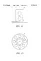
- FIG. 1is a perspective view of a mounting system for body mounted camera equipment including a video monitor and a battery hanger.
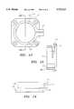
- FIG. 2is a perspective view of the lower portion of the mount with the tube assembly disengaged.
- FIG. 3is a cross-sectional view taken along line 3--3 of FIG. 2.
- FIG. 4is an exploded perspective view of a tube assembly lock.
- FIG. 5is a perspective view of the lower mount with the clamp disassembled.
- FIG. 6is a cross-sectional elevation taken along line 6--6 of FIG. 2.
- FIG. 7is a top view of the inner collar associated with the tube assembly.
- FIG. 8is a side view of the collar of FIG. 7.
- FIG. 9is a plan view of the mounting.
- FIG. 10is a cross-sectional side view taken along line 10--10 of FIG. 9.
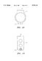
- FIG. 11is a side view of the connector sleeve.
- FIG. 12is a plan view of the connector sleeve.
- FIG. 13is a plan view of the clamp.
- FIG. 14is a side view of the clamp.
- FIG. 15is a cross-sectional view taken along line 15--15 of FIG. 13.
- FIG. 16is an end view of the junction box cover illustrating the mortise.
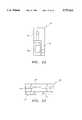
- FIG. 17is a side view of an assembled universal gyro mount.
- FIG. 18is a side view of a junction box mounting for the universal gyro mount.
- FIG. 19is a front view of the mount of FIG. 18.
- FIG. 20is a side view of a mounting flange associated with the universal gyro mount.
- FIG. 21is a side view of a clamp ring mount to go on the universal gyro mount.
- FIG. 22is a side view of a flange clamp.
- FIG. 23is a first end view of the flange clamp.
- FIG. 24is the opposite end view from FIG. 24 of the flange clamp.
- FIG. 25is a cross-sectional view taken along line 25--25 of FIG. 23.
- FIG. 1illustrates a first set-up for such equipment.
- the assemblyis to be coupled with a series of links or arms which are mounted to the body of a cameraman by a harness.
- the mounting systemincludes a tube assembly, generally designated 20, having two telescoping tubes 22 and 24.
- the length of the tube assembly 20may be varied through sliding of the smaller tube 22 within the larger tube 24.
- a tube locking mechanismfixes the length of the tube assembly as desired.
- This mechanismincludes a clamp retainer 26 slidably received within the smaller tube 22.
- a locating window 28 in the clamp retainer 26receives a post clamp 30.
- the smaller tube 22includes a slot 32 which may be aligned with a hole through the lower end portion of the larger tube 24.
- a collar 34includes a smaller section 36 which fits within the slot 32 and a larger section 38 which is larger than the hole in the tube 24. This collar 34 is retained in place by a bolt 40 extending into the post clamp 30.
- An alignment bolt 42also threaded into the post clamp 30 is positioned within the slot 32.
- a three-axis gimbal 44Mounted to the tube assembly 20 is a three-axis gimbal 44.
- An arm 46is rotatably mounted to a yoke 48.
- the yokeis pivotally mounted about trunnions 50 and the tube assembly 20 can rotate about its longitudinal axis within a collar 52.
- the free end of the arm 46is adapted to be mounted to the distal end of an articulated arm which can in turn be mounted to a harness which can be worn by a cameraman.
- a video monitor 54is associated with the tube assembly 20 using a monitor bracket 56 held in place around the tube assembly 20 by a clamp ring 58.
- a plate(not visible) is associated with an upper junction box 60 and an adjustable platform 62 to define an upper attachment.
- This mechanismis designed to receive, for example, a motion picture camera or video camera.
- a battery hanger 64including batteries 66.
- the battery hanger 64is associated with a junction box 68.
- the junction box 68provides a lower attachment defined by a lid 72 illustrated in end view in FIG. 16.
- the lid 72includes a mortise defined by inwardly extending rails 74.
- the lid 72is shown to include a slot 76 for receipt of cabling.
- an inner collargenerally designated 78, best seen in FIGS. 7 and 8 is associated with the smaller tube 22 at the lower end of the tube assembly 20.
- the inner collar 78includes a cylindrical body 80 which has screw holes 82 for attachment to the tube 22.
- a flange 84extends outwardly to abut against one end of the tube 22.
- Enlarged diametrically opposed flanges 86extend outwardly from the flange 84 to beyond the outer diameter of the smaller tube 22.
- a mounting 88is illustrated in FIGS. 9 and 10.
- This mounting 88defines a tenon by its sloped sides. The tenon fits within the mortise defined by the rails 74 and allows for adjustment of the junction box 68 relative to the mounting 88 for the achievement of a balanced system.
- a connector sleeve 90is illustrated in FIGS. 11 and 12.
- the connector sleeve 90includes a threaded inner bore 92.
- a flange 94is located at one end of the connector sleeve 90.
- a hole 96is centrally positioned on the mounting 88 with a recessed ring 98.
- the recessed ring 98receives the flange 94.
- a connector 100illustrated in FIG. 1, may be threadably retained within the bore 92 of the connector sleeve 90 with a flexible conductor extending into the junction box 68 through the slot 76.
- a clamp 102is mounted to the mounting 88 by fasteners 104.
- the clampincludes a mounting plate 106 to accommodate the fasteners 104.
- the plate 106also is positioned over the outer portion of the flange 94 to retain the connector sleeve 90 in position.
- a compressible split clamp ring 108is integrally formed atop the mounting plate 106.
- the ring 108is cut away from the mounting plate 106 about one half of its extent. Consequently, the ring acquires compressible properties.
- tabs 110are provided to either side of the split in the ring 108.
- a hole 112 in each tabaccommodates a fastener for forcefully drawing the ring closer together.
- a bore 114extends through the clamp ring 108 and mounting plate 106. This bore 114 includes longitudinally extending grooves 116 sized to accommodate the flanges 68. The remainder of the bore 114 is sized to accommodate the flange 84 and the associated smaller tube 22.
- the lower end of the tube assembly 20can be inserted into the clamp 102.
- the mounting plate 106has an inner shoulder 118 at the lower end of the bore 114.
- the flanges 86will drop below the inner shoulder 118.
- the tube assembly 20can then be rotated to interlock the flanges 86 with the inner shoulder 118 and the mounting plate 106.
- the clamp ring 108may be tightened to securely retain the tube assembly 20 from rotating so that the flanges 68 will not disengage from the inner shoulder 118.
- a second connector 120Coupled with the connector 100 is a second connector 120.
- This second connector 120includes an extendable cable 122 having coils 124. The extendibility of the cable 122 allows the connectors 100 and 120 to be mated prior to the positioning of the lower end of the tube assembly 20 into the clamp 102. The fully assembled junction is illustrated in FIG. 6.
- the foregoing mechanism for assembling the tube assembly 20 with the lower attachmentprovides a secured relationship between the components, adequate support for the battery hanger 64, and a modular arrangement for rapid interchanging of equipment.
- FIGS. 17 through 25a universal gyro mount is disclosed. This system may be employed in the position occupied by the battery hanger 64 in the system configuration discussed above. Configurations for multiple such systems to be hung on the same mounting system can be devised. However, it is understood to be advantageous to use a backpack or belt arrangement for batteries when employing a gyro mounting system.
- the mountincludes an elongate element, generally designated 126.
- This elongate element 126is conveniently made of two tubes 128 and 130 telescoped together. A mechanism similar to that of the main tube assembly may be used in locking the tubes 128 and 130 together. Thus, a first degree of freedom is provided with the system through the extension or retraction of the elongate element assembly 126.
- This elongate element 126is supported on the underside of a junction box, such as the junction box 68 described in the aforementioned configuration mounting a battery hanger 64.
- An adaptor plate 132is shown associated with the underside junction box 68. This adaptor plate 132 provides threaded holes for receipt of the universal gyro mount. The plate exhibits sufficient symmetry such that the universal gyro mount may be oriented in the plane of a camera attached to the adjustable platform 62 or normal to that plane.
- FIGS. 18 and 19illustrate a junction box mount 134 which attaches to the adaptor plate 132.
- the mount 134is principally a clamp ring with a boss 136 having holes to mate with the adaptor plate 132 through the use of fasteners.
- the clamp ring 134is split with tabs 138 to allow constriction of the ring for clamping onto the elongate element 126.
- a further degree of freedomis provided in that the elongate element 126 may be moved longitudinally through a releasing of the clamp ring 134.
- FIG. 20illustrates one mounting flange, generally designated 140.
- This mounting flange 140is typical of three or more mounting flanges defining gyro attachments on the universal gyro mount.
- the mounting flange 140includes a cylindrical body 142 which is associated with one or the other of the tubes 128 and 130 of the elongate element 126. Taps 144 extend through the body 142 for attachment to the tubes 128 and 130.
- An outwardly extending flange 146is designed to abut against the ends of the tubes 128 and 130.
- An attachment flange 148is defined at the outer ring of the mounting flange 140 by the presence of an annular channel 150 in a smaller cylindrical body portion 152.
- the clamp ring mount 154includes a first segment 156 and a second segment 158 which together define an enclosing circular gripping surface for location on the elongate element 126.
- the second segment 158includes an integrally mounting flange 140 having an identical attachment 148 defined by a channel 150 as is true of the mounting flange 140.
- Flange clampsare attachable to the attachment flanges 148.
- the flange clamps 166are illustrated in FIGS. 22 through 25. These clamps 166 are fixed to rotatable flywheels 168 which contribute the gyroscopic response for stabilizing the mounting system.
- Each flange clamp 166includes a mounting plate 170.
- the mounting plate 170includes a counter-sunk through hole 172 to receive a fastener for attachment to the flywheel 168.
- a first enclosure segment 174is integrally formed with the mounting plate 170. This segment includes an attachment channel 176 having a profiled cross-section to mate with the attachment flange 148, the channel 150 and the small cylindrical body 152 of the mounting flange 140.
- a second enclosure segment 178opposes the first enclosure segment 174.
- This segment 178is attached to the first segment 174 by means of a pivotally mounted link 180 and a fastener.
- the second segment 178includes an attachment channel 182 complimentary to the attachment channel 176 so as to surround and retain the attachment flange 148 of the mounting flange 140.
- the universal gyro mountprovides three or more attachments for flywheels which operate to provide a gyroscopic response to stabilization.
- Two such flywheels 168may be associated with the ends of the elongate element 126.
- Other available attachment pointsinclude the full length of the elongate element 126 by means of one or more clamp ring mounting elements 154.
- the length of the elongate element 126can also be varied.
- the orientation of the elongate element 126 as either aligned with the plane of the camera or normal theretoprovides a further degree of freedom.
- the flange clamps 166may be loosened to permit rotation of the attached flywheel housings for desired orientation of the axis of the flywheels 168.
- the universal gyro mountmay operate on a modular basis for attachment and detachment from the line system.
Landscapes
- Engineering & Computer Science (AREA)
- General Engineering & Computer Science (AREA)
- Mechanical Engineering (AREA)
- Physics & Mathematics (AREA)
- General Physics & Mathematics (AREA)
- Accessories Of Cameras (AREA)
Abstract
Description
The field of the present invention is structural hardware employed with body mounted camera equipment.
Body mounted cameras have been available for some time. Such cameras frequently are too heavy to be hand-carried or require a more stable platform. Where only weight is a factor, shoulder supported cameras have been used. Where stability is needed, mounting with resilient linkage to the operator's body is preferred. An early such body mounted camera support system is illustrated in U.S. Pat. No. 4,156,512, the disclosure of which is incorporated herein by reference.
Portable camera systems as employed for motion picture filming and the like typically include a fairly substantial camera, a large film magazine, batteries and a video monitoring system. With body mounted systems, a sprung mounting structure is typically employed to support all components. The components are frequently arranged to add stability to the sprung mass. Consequently, weight is shifted away from the support to increase angular inertia. The center of gravity is also carefully located to establish stability with the camera vertically oriented and without inducing excessive restoring forces.
In addition to the structural set-up for stability, flywheels have been employed to institute gyroscopic forces. Through the orientation of two such flywheels, impermissible motion in specific directions have been found to be significantly reduced. A variety of flywheel orientations have been empirically determined, depending upon the camera motions, both desired and unwanted.
The mountings of the various components of the camera system are required to be tight and secure to avoid adverse visual effects. Rigid mountings have been developed which satisfy those demands. However, a lack of flexibility in changing components has also been experienced.
The present invention is directed to a mounting system for elements associated with a body mounted camera.
In a first and separate aspect of the present invention, a mounting system employing a clamp is associated with the lower end of a mounting tube for providing a secure coupling for system components, and at the same time for providing a quick release. The structural tube of the body mounted camera equipment includes flanges extending outwardly. A mounting plate includes a bore with shoulders to receive the end of the tube with the flanges. Through rotation of the mounting relative to the tube, a shoulder can be engaged by a flange for support of the mounting and all equipment affixed thereto. A split clamp ring is associated with the mounting and receives the tube. The clamp ring can be tightened to fix the entire assembly in place.
In a second and separate aspect of the present invention, the clamp of the first aspect may be associated with a connector sleeve positioned within the mounting, a first connector positioned within the sleeve and a second connector associated with the structural tube to provide electrical communication between elements of the system.
In a third and separate aspect of the present invention, the mounting system of the first aspect further includes a tenon and mortise coupling between the clamp and an associated junction box. This system accommodates adjustments in component positioning to establish a desired system center of gravity.
In a fourth and separate aspect of the present invention, the mounting system of the first aspect might further include a universal gyro mount having multiple flywheel mounts for added system stability.
In a fifth and separate aspect of the present invention, a mounting system for body mounted camera equipment includes a universal gyro mount having an elongate element associated with the mounting. The elongate element includes two ends which may be displaced laterally from the mounting and have attachments for flywheels operated to induce gyroscopic forces. One or more additional mounts may be selectively oriented along the element with similar gyro attachments. The attachments provide for variable angular positioning of the flywheel gyros. The universal gyro mount provides the ability to position two or more gyros to stabilize desired camera movement for filming.
Accordingly, it is an object of the present invention to provide an improved body mounted camera mounting system. Other and further objects and advantages will become apparent from the following.
FIG. 1 is a perspective view of a mounting system for body mounted camera equipment including a video monitor and a battery hanger.
FIG. 2 is a perspective view of the lower portion of the mount with the tube assembly disengaged.
FIG. 3 is a cross-sectional view taken alongline 3--3 of FIG. 2.
FIG. 4 is an exploded perspective view of a tube assembly lock.
FIG. 5 is a perspective view of the lower mount with the clamp disassembled.
FIG. 6 is a cross-sectional elevation taken alongline 6--6 of FIG. 2.
FIG. 7 is a top view of the inner collar associated with the tube assembly.
FIG. 8 is a side view of the collar of FIG. 7.
FIG. 9 is a plan view of the mounting.
FIG. 10 is a cross-sectional side view taken alongline 10--10 of FIG. 9.
FIG. 11 is a side view of the connector sleeve.
FIG. 12 is a plan view of the connector sleeve.
FIG. 13 is a plan view of the clamp.
FIG. 14 is a side view of the clamp.
FIG. 15 is a cross-sectional view taken alongline 15--15 of FIG. 13.
FIG. 16 is an end view of the junction box cover illustrating the mortise.
FIG. 17 is a side view of an assembled universal gyro mount.
FIG. 18 is a side view of a junction box mounting for the universal gyro mount.
FIG. 19 is a front view of the mount of FIG. 18.
FIG. 20 is a side view of a mounting flange associated with the universal gyro mount.
FIG. 21 is a side view of a clamp ring mount to go on the universal gyro mount.
FIG. 22 is a side view of a flange clamp.
FIG. 23 is a first end view of the flange clamp.
FIG. 24 is the opposite end view from FIG. 24 of the flange clamp.
FIG. 25 is a cross-sectional view taken alongline 25--25 of FIG. 23.
A mounting system for body mounted camera equipment is illustrated in the accompanying drawings. FIG. 1 illustrates a first set-up for such equipment. The assembly is to be coupled with a series of links or arms which are mounted to the body of a cameraman by a harness. Reference is made to U.S. Pat. Nos. 4,017,168 and 4,208,028, the disclosures of which are incorporated herein by reference.
The mounting system includes a tube assembly, generally designated 20, having twotelescoping tubes tube assembly 20 may be varied through sliding of thesmaller tube 22 within thelarger tube 24. A tube locking mechanism fixes the length of the tube assembly as desired. This mechanism includes aclamp retainer 26 slidably received within thesmaller tube 22. A locatingwindow 28 in theclamp retainer 26 receives apost clamp 30. Thesmaller tube 22 includes aslot 32 which may be aligned with a hole through the lower end portion of thelarger tube 24. Acollar 34 includes asmaller section 36 which fits within theslot 32 and alarger section 38 which is larger than the hole in thetube 24. Thiscollar 34 is retained in place by abolt 40 extending into thepost clamp 30. Analignment bolt 42 also threaded into thepost clamp 30 is positioned within theslot 32. By tightening thebolt 40, thepost clamp 30 and thelarger section 38 of thecollar 34 clamp the twotubes
Mounted to thetube assembly 20 is a three-axis gimbal 44. Anarm 46 is rotatably mounted to ayoke 48. The yoke is pivotally mounted abouttrunnions 50 and thetube assembly 20 can rotate about its longitudinal axis within acollar 52. The free end of thearm 46 is adapted to be mounted to the distal end of an articulated arm which can in turn be mounted to a harness which can be worn by a cameraman.
Avideo monitor 54 is associated with thetube assembly 20 using amonitor bracket 56 held in place around thetube assembly 20 by aclamp ring 58.
A plate (not visible) is associated with anupper junction box 60 and anadjustable platform 62 to define an upper attachment. This mechanism is designed to receive, for example, a motion picture camera or video camera.
Associated with the bottom end of thetube assembly 20 is abattery hanger 64 includingbatteries 66. Thebattery hanger 64 is associated with ajunction box 68. Thejunction box 68 provides a lower attachment defined by alid 72 illustrated in end view in FIG. 16. Thelid 72 includes a mortise defined by inwardly extending rails 74. Thelid 72 is shown to include aslot 76 for receipt of cabling.
To mount the lower attachment to thetube assembly 20, an inner collar, generally designated 78, best seen in FIGS. 7 and 8 is associated with thesmaller tube 22 at the lower end of thetube assembly 20. Theinner collar 78 includes acylindrical body 80 which has screw holes 82 for attachment to thetube 22. At one end of thecylinder body 80, aflange 84 extends outwardly to abut against one end of thetube 22. Enlarged diametricallyopposed flanges 86 extend outwardly from theflange 84 to beyond the outer diameter of thesmaller tube 22.
A mounting 88 is illustrated in FIGS. 9 and 10. This mounting 88 defines a tenon by its sloped sides. The tenon fits within the mortise defined by therails 74 and allows for adjustment of thejunction box 68 relative to the mounting 88 for the achievement of a balanced system.
Aconnector sleeve 90 is illustrated in FIGS. 11 and 12. Theconnector sleeve 90 includes a threadedinner bore 92. Aflange 94 is located at one end of theconnector sleeve 90. As seen in FIGS. 9 and 10, ahole 96 is centrally positioned on the mounting 88 with a recessedring 98. The recessedring 98 receives theflange 94. Aconnector 100, illustrated in FIG. 1, may be threadably retained within thebore 92 of theconnector sleeve 90 with a flexible conductor extending into thejunction box 68 through theslot 76.
Aclamp 102 is mounted to the mounting 88 byfasteners 104. The clamp includes a mountingplate 106 to accommodate thefasteners 104. Theplate 106 also is positioned over the outer portion of theflange 94 to retain theconnector sleeve 90 in position.
A compressiblesplit clamp ring 108 is integrally formed atop the mountingplate 106. Thering 108 is cut away from the mountingplate 106 about one half of its extent. Consequently, the ring acquires compressible properties. To control the compression of thering 108,tabs 110 are provided to either side of the split in thering 108. Ahole 112 in each tab accommodates a fastener for forcefully drawing the ring closer together. Abore 114 extends through theclamp ring 108 and mountingplate 106. This bore 114 includes longitudinally extendinggrooves 116 sized to accommodate theflanges 68. The remainder of thebore 114 is sized to accommodate theflange 84 and the associatedsmaller tube 22. Thus, the lower end of thetube assembly 20 can be inserted into theclamp 102. The mountingplate 106 has aninner shoulder 118 at the lower end of thebore 114. By fitting the lower end of thetube assembly 20 down into thebore 114, theflanges 86 will drop below theinner shoulder 118. Thetube assembly 20 can then be rotated to interlock theflanges 86 with theinner shoulder 118 and the mountingplate 106. Once in this position, theclamp ring 108 may be tightened to securely retain thetube assembly 20 from rotating so that theflanges 68 will not disengage from theinner shoulder 118.
Coupled with theconnector 100 is asecond connector 120. Thissecond connector 120 includes anextendable cable 122 havingcoils 124. The extendibility of thecable 122 allows theconnectors tube assembly 20 into theclamp 102. The fully assembled junction is illustrated in FIG. 6.
The foregoing mechanism for assembling thetube assembly 20 with the lower attachment provides a secured relationship between the components, adequate support for thebattery hanger 64, and a modular arrangement for rapid interchanging of equipment.
Turning to FIGS. 17 through 25, a universal gyro mount is disclosed. This system may be employed in the position occupied by thebattery hanger 64 in the system configuration discussed above. Configurations for multiple such systems to be hung on the same mounting system can be devised. However, it is understood to be advantageous to use a backpack or belt arrangement for batteries when employing a gyro mounting system.
The mount includes an elongate element, generally designated 126. Thiselongate element 126 is conveniently made of twotubes tubes elongate element assembly 126.
Thiselongate element 126 is supported on the underside of a junction box, such as thejunction box 68 described in the aforementioned configuration mounting abattery hanger 64. Anadaptor plate 132 is shown associated with theunderside junction box 68. Thisadaptor plate 132 provides threaded holes for receipt of the universal gyro mount. The plate exhibits sufficient symmetry such that the universal gyro mount may be oriented in the plane of a camera attached to theadjustable platform 62 or normal to that plane.
FIGS. 18 and 19 illustrate ajunction box mount 134 which attaches to theadaptor plate 132. Themount 134 is principally a clamp ring with aboss 136 having holes to mate with theadaptor plate 132 through the use of fasteners. Theclamp ring 134 is split withtabs 138 to allow constriction of the ring for clamping onto theelongate element 126. A further degree of freedom is provided in that theelongate element 126 may be moved longitudinally through a releasing of theclamp ring 134.
FIG. 20 illustrates one mounting flange, generally designated 140. This mountingflange 140 is typical of three or more mounting flanges defining gyro attachments on the universal gyro mount. The mountingflange 140 includes acylindrical body 142 which is associated with one or the other of thetubes elongate element 126.Taps 144 extend through thebody 142 for attachment to thetubes flange 146 is designed to abut against the ends of thetubes attachment flange 148 is defined at the outer ring of the mountingflange 140 by the presence of anannular channel 150 in a smallercylindrical body portion 152.
One of the mountingflanges 140 is associated with the universal gyro mount through a clamp ring mount, generally designated 154. Theclamp ring mount 154 includes afirst segment 156 and asecond segment 158 which together define an enclosing circular gripping surface for location on theelongate element 126. At one interface between thesegments links 160 are joined to the segments bypins 162. The other interface between the segments includes a swing-lock closure to draw themount 154 into solid engagement with theelongate element 126. Thesecond segment 158 includes an integrally mountingflange 140 having anidentical attachment 148 defined by achannel 150 as is true of the mountingflange 140.
Flange clamps, generally designated 166, are attachable to theattachment flanges 148. The flange clamps 166 are illustrated in FIGS. 22 through 25. Theseclamps 166 are fixed torotatable flywheels 168 which contribute the gyroscopic response for stabilizing the mounting system. Eachflange clamp 166 includes a mountingplate 170. The mountingplate 170 includes a counter-sunk throughhole 172 to receive a fastener for attachment to theflywheel 168. Afirst enclosure segment 174 is integrally formed with the mountingplate 170. This segment includes anattachment channel 176 having a profiled cross-section to mate with theattachment flange 148, thechannel 150 and the smallcylindrical body 152 of the mountingflange 140. Asecond enclosure segment 178 opposes thefirst enclosure segment 174. Thissegment 178 is attached to thefirst segment 174 by means of a pivotally mountedlink 180 and a fastener. Thesecond segment 178 includes anattachment channel 182 complimentary to theattachment channel 176 so as to surround and retain theattachment flange 148 of the mountingflange 140.
The universal gyro mount provides three or more attachments for flywheels which operate to provide a gyroscopic response to stabilization. Twosuch flywheels 168 may be associated with the ends of theelongate element 126. Other available attachment points include the full length of theelongate element 126 by means of one or more clampring mounting elements 154. The length of theelongate element 126 can also be varied. The orientation of theelongate element 126 as either aligned with the plane of the camera or normal thereto provides a further degree of freedom. Finally, the flange clamps 166 may be loosened to permit rotation of the attached flywheel housings for desired orientation of the axis of theflywheels 168. By virtue of theclamp 102, the universal gyro mount may operate on a modular basis for attachment and detachment from the line system.
Accordingly, an improved mounting system for body mounted camera equipment is disclosed which provides modular convenience and system stability. Although embodiments and applications of this invention have been shown and described, it would be apparent to those skilled in the art that many more modifications are possible without departing from the inventive concepts herein. The invention, therefore, is not to be restricted except in the spirit of the appended claims.
Claims (17)
1. A mounting system for body mounted camera equipment, comprising
a tube assembly including a tube having a first, upper end and a second, lower end, the second, lower end having flanges extending radially outwardly from the tube;
a first attachment on the first, upper end of the tube assembly;
a second attachment;
a clamp including a mounting fixed to the second attachment, a split clamp ring fixed to the mounting, a bore through the split clamp ring and the mounting, grooves in the split clamp ring and the mounting extending longitudinally about the periphery of the bore and sized to axially receive the flanges, the mounting having a shoulder adjacent the grooves to receive and inter-engage the flanges through placement and rotation of the second, lower end of the tube assembly in the clamp, the split clamp ring being axially compressible against the second, lower end.
2. The mounting system of claim 1 further comprising
a connector sleeve positioned on the mounting and extending upwardly in the bore;
a first connector positioned in the connector sleeve;
an extendable cable extending from the first attachment through the tube assembly and having a second connector slidably positioned at the second, lower end of the tube assembly to mate with the first connector.
3. The mounting system of claim 1, the second, lower end of the tube assembly including an inner collar fixed to the tube, the inner collar having the flanges.
4. The mounting system of claim 1, the flanges and grooves being two each, oppositely disposed on the tube assembly and the clamp, respectively.
5. The mounting system of claim 1, the compressible split clamp ring having two tabs to either side of the split, respectively, one half of the clamp ring from one tab being fixed to the mounting and the other half of the clamp ring from the other tab being separate from the mounting.
6. The mounting system of claim 5, the tabs including holes, the compressible split clamp ring further having a fastener associated with the holes to compress the split clamp ring.
7. The mounting system of claim 1, the second attachment including a tenon.
8. The mounting system of claim 7 further comprising
a junction box including a mortise, the tenon being slidable in the mortise.
9. The mounting system of claim 8 further comprising a battery hanger fixed to the junction box.
10. The mounting system of claim 8 further comprising a universal gyro mount fixed to the junction box.
11. The mounting system of claim 1 further comprising a universal gyro mount supported by the second attachment.
12. The mounting system of claim 11, the universal gyro mount including an elongate element and three gyro attachments each having an axis, a first and a second of the gyro attachments being at either end of the elongate element with the axes aligned, the third of the gyro attachments including an attachment clamp on the elongate element with the axis of the attachment being perpendicular to the axes of the first and second of the gyro attachments.
13. The mounting system of claim 12, the elongate element including two attachment tubes slidably telescoped together.
14. The mounting system of claim 12, the universal gyro mount further including gyro clamps, each having a first annular channel and a second annular channel adjacent the first annular channel, the gyro attachments each including an annular flange mating with a first annular clamp, respectively.
15. A mounting system for body mounted camera equipment, comprising
a tube assembly including a tube having a first, upper end and a second, lower end, the second, lower end having flanges extending radially outwardly from the tube;
a first attachment on the first, upper end of the tube assembly;
a second attachment on the second, lower end of the tube assembly;
a universal gyro mount supported by the second attachment the universal gyro mount including an elongate element and three gyro attachments each having an axis, a first and a second of the gyro attachments being at either end of the elongate element with the axes aligned, the third of the gyro attachments including an attachment clamp on the elongate element with the axis of the attachment being perpendicular to the axes of the first and second of the gyro attachments.
16. The mounting system of claim 15, the elongate element including two attachment tubes slidably telescoped together.
17. The mounting system of claim 15, the universal gyro mount further including gyro clamps, each having a first annular channel and a second annular channel adjacent the first annular channel, the gyro attachments each including an annular flange mating with a first annular clamp, respectively.
Priority Applications (1)
| Application Number | Priority Date | Filing Date | Title |
|---|---|---|---|
| US08/746,204US5752112A (en) | 1996-11-06 | 1996-11-06 | Mounting system for body mounted camera equipment |
Applications Claiming Priority (1)
| Application Number | Priority Date | Filing Date | Title |
|---|---|---|---|
| US08/746,204US5752112A (en) | 1996-11-06 | 1996-11-06 | Mounting system for body mounted camera equipment |
Publications (1)
| Publication Number | Publication Date |
|---|---|
| US5752112Atrue US5752112A (en) | 1998-05-12 |
Family
ID=24999878
Family Applications (1)
| Application Number | Title | Priority Date | Filing Date |
|---|---|---|---|
| US08/746,204Expired - LifetimeUS5752112A (en) | 1996-11-06 | 1996-11-06 | Mounting system for body mounted camera equipment |
Country Status (1)
| Country | Link |
|---|---|
| US (1) | US5752112A (en) |
Cited By (72)
| Publication number | Priority date | Publication date | Assignee | Title |
|---|---|---|---|---|
| US6030130A (en)* | 1997-07-07 | 2000-02-29 | George Paddock Ii, Inc. | Body mounted camera support system |
| US6293676B1 (en)* | 1998-02-17 | 2001-09-25 | Garrett W. Brown | Camera support including extendable post |
| WO2002081962A1 (en)* | 2001-04-06 | 2002-10-17 | Howard James Smith | Support apparatus for a body mountable camera and method of stabilising such a camera |
| US6578967B1 (en)* | 2001-03-15 | 2003-06-17 | George Paddock Ii, Inc. | Mounting system for body mounted camera equipment and connector assemblies therefor |
| GB2387538A (en)* | 2002-04-19 | 2003-10-22 | Howard James Smith | Telescopic camera support with gimbal adjustment |
| FR2847653A1 (en)* | 2002-11-27 | 2004-05-28 | Francis Sadier | Adjustable and articulate device for video camera, has clip and telescopic system that links handle of camera to eyepiece of camera, where clip is fixed opposite to eyepiece of camera |
| US20040135879A1 (en)* | 2003-01-03 | 2004-07-15 | Stacy Marco A. | Portable wireless indoor/outdoor camera |
| FR2852665A1 (en)* | 2003-03-17 | 2004-09-24 | Pierre Andre Davezac | Stabilizer for e.g. light videographic camera, has handle fixed on one plate that concentrates adjustments for static and dynamic equilibrium of camera and stabilizer by letting handle to move along three dimensional axes |
| US20040217240A1 (en)* | 2003-05-01 | 2004-11-04 | George Paddock Ii, Inc. | Post mounting system |
| US20050031336A1 (en)* | 2001-09-13 | 2005-02-10 | Schaller Curt O | Cardanic suspension device for a camera balance device |
| US20050036781A1 (en)* | 2001-09-13 | 2005-02-17 | Schaller Curt O | Cardanic suspension device for a camera balance device |
| US20050053371A1 (en)* | 2001-09-13 | 2005-03-10 | Schaller Curt O. | Decoupled weight compensation system for a camera balance-device |
| GB2410569A (en)* | 2004-01-29 | 2005-08-03 | Howard James Smith | Balanced portable camera support comprising a multi-component mounting system |
| US20060239678A1 (en)* | 2004-08-02 | 2006-10-26 | Arnold Itzkowitz | Stable platform for image capturing |
| US20070058075A1 (en)* | 2005-09-09 | 2007-03-15 | Anton/Bauer, Inc. | Camera system and power supply for optical recording devices |
| RU2315951C1 (en)* | 2006-06-09 | 2008-01-27 | Государственное образовательное учреждение высшего профессионального образования "Московский физико-технический институт (государственный университет)" | Onboard system for local aero-monitoring of objects of natural and technogenic sphere |
| US20080065105A1 (en)* | 2006-06-13 | 2008-03-13 | Intuitive Surgical, Inc. | Minimally invasive surgical system |
| USD565632S1 (en)* | 2006-05-05 | 2008-04-01 | Csav, Inc. | Adjustable mounting column |
| US20080287963A1 (en)* | 2005-12-30 | 2008-11-20 | Rogers Theodore W | Methods and apparatus to shape flexible entry guides for minimally invasive surgery |
| US20090002524A1 (en)* | 2005-09-09 | 2009-01-01 | Anton/Bauer, Inc. | Camera system and power supply for optical recording devices |
| AU2002337088B2 (en)* | 2001-09-13 | 2009-05-21 | Camera Dynamics Gmbh | Camera support device worn on the body comprising a multifunctional assembly of electrical components |
| RU2362195C1 (en)* | 2008-03-25 | 2009-07-20 | Ральф Роландович Келли | Movable stabilised mounting for panoramic film shooting |
| US20100124414A1 (en)* | 2008-11-14 | 2010-05-20 | Brown Garrett W | Extendable camera support and stabilization apparatus |
| EA013800B1 (en)* | 2009-04-08 | 2010-06-30 | Научно-Исследовательское Учреждение "Институт Прикладных Физических Проблем Имени А.Н. Севченко" Белорусского Государственного Университета | Aerial optical complex with high spatial and spectral resolution with automatic adaptive control |
| US20100266272A1 (en)* | 2009-04-20 | 2010-10-21 | Jerry Holway | Folding Camera Support with Rotational Inertia Adjustment |
| US20100278523A1 (en)* | 2008-11-14 | 2010-11-04 | Brown Garrett W | Extendable camera support and stabilization apparatus |
| US20100301179A1 (en)* | 2007-09-17 | 2010-12-02 | Brown Garrett W | Gimbal assembly for tool support |
| US20110080563A1 (en)* | 2009-10-07 | 2011-04-07 | Greaves Nigel J | Gimbaled handle stabilizing controller assembly |
| US20110170534A1 (en)* | 2010-01-11 | 2011-07-14 | Faro Technologies, Inc. | Method and apparatus for synchronizing measurements taken by multiple metrology devices |
| US20110178753A1 (en)* | 2010-01-20 | 2011-07-21 | Faro Technologies, Inc. | Portable Articulated Arm Coordinate Measuring Machine and Integrated Environmental Recorder |
| US20110173827A1 (en)* | 2010-01-20 | 2011-07-21 | Faro Technologies, Inc. | Coordinate measurement machines with removable accessories |
| US20110176148A1 (en)* | 2010-01-20 | 2011-07-21 | Faro Technologies, Inc. | Coordinate measuring machine having an illuminated probe end and method of operation |
| US20110224684A1 (en)* | 2005-12-30 | 2011-09-15 | Intuitive Surgical Operations, Inc. | Robotic surgery system including position sensors using fiber bragg gratings |
| CN102374373A (en)* | 2010-08-16 | 2012-03-14 | 中强光电股份有限公司 | Lifting module |
| US8506180B2 (en) | 2008-11-14 | 2013-08-13 | Garrett W. Brown | Extendable camera support and stabilization apparatus |
| US8585205B2 (en) | 2009-10-07 | 2013-11-19 | Nigel J. Greaves | Gimbaled handle stabilizing controller assembly |
| USD696336S1 (en)* | 2009-12-30 | 2013-12-24 | Red.Com, Inc. | Camera component |
| US8615893B2 (en) | 2010-01-20 | 2013-12-31 | Faro Technologies, Inc. | Portable articulated arm coordinate measuring machine having integrated software controls |
| US8638446B2 (en) | 2010-01-20 | 2014-01-28 | Faro Technologies, Inc. | Laser scanner or laser tracker having a projector |
| US8677643B2 (en) | 2010-01-20 | 2014-03-25 | Faro Technologies, Inc. | Coordinate measurement machines with removable accessories |
| US8746252B2 (en) | 2010-05-14 | 2014-06-10 | Intuitive Surgical Operations, Inc. | Surgical system sterile drape |
| US8801302B2 (en)* | 2012-11-26 | 2014-08-12 | The Tiffen Company, Llc | Camera stabilizer |
| US8804030B2 (en) | 2010-04-08 | 2014-08-12 | Anton/Bauer, Inc. | Camera system and power supply for optical recording devices |
| US8832954B2 (en) | 2010-01-20 | 2014-09-16 | Faro Technologies, Inc. | Coordinate measurement machines with removable accessories |
| US8875409B2 (en) | 2010-01-20 | 2014-11-04 | Faro Technologies, Inc. | Coordinate measurement machines with removable accessories |
| US8898919B2 (en) | 2010-01-20 | 2014-12-02 | Faro Technologies, Inc. | Coordinate measurement machine with distance meter used to establish frame of reference |
| US8997362B2 (en) | 2012-07-17 | 2015-04-07 | Faro Technologies, Inc. | Portable articulated arm coordinate measuring machine with optical communications bus |
| US9074883B2 (en) | 2009-03-25 | 2015-07-07 | Faro Technologies, Inc. | Device for optically scanning and measuring an environment |
| US9113023B2 (en) | 2009-11-20 | 2015-08-18 | Faro Technologies, Inc. | Three-dimensional scanner with spectroscopic energy detector |
| US9163922B2 (en) | 2010-01-20 | 2015-10-20 | Faro Technologies, Inc. | Coordinate measurement machine with distance meter and camera to determine dimensions within camera images |
| US9168654B2 (en) | 2010-11-16 | 2015-10-27 | Faro Technologies, Inc. | Coordinate measuring machines with dual layer arm |
| US9210288B2 (en) | 2009-11-20 | 2015-12-08 | Faro Technologies, Inc. | Three-dimensional scanner with dichroic beam splitters to capture a variety of signals |
| US9329271B2 (en) | 2010-05-10 | 2016-05-03 | Faro Technologies, Inc. | Method for optically scanning and measuring an environment |
| US9372265B2 (en) | 2012-10-05 | 2016-06-21 | Faro Technologies, Inc. | Intermediate two-dimensional scanning with a three-dimensional scanner to speed registration |
| US9387048B2 (en) | 2011-10-14 | 2016-07-12 | Intuitive Surgical Operations, Inc. | Catheter sensor systems |
| US9417316B2 (en) | 2009-11-20 | 2016-08-16 | Faro Technologies, Inc. | Device for optically scanning and measuring an environment |
| US9417056B2 (en) | 2012-01-25 | 2016-08-16 | Faro Technologies, Inc. | Device for optically scanning and measuring an environment |
| US9452276B2 (en) | 2011-10-14 | 2016-09-27 | Intuitive Surgical Operations, Inc. | Catheter with removable vision probe |
| US9513107B2 (en) | 2012-10-05 | 2016-12-06 | Faro Technologies, Inc. | Registration calculation between three-dimensional (3D) scans based on two-dimensional (2D) scan data from a 3D scanner |
| US9529083B2 (en) | 2009-11-20 | 2016-12-27 | Faro Technologies, Inc. | Three-dimensional scanner with enhanced spectroscopic energy detector |
| US9534730B2 (en) | 2010-08-26 | 2017-01-03 | Garrett W. Brown | Multi-arm gimbal system |
| US9551575B2 (en) | 2009-03-25 | 2017-01-24 | Faro Technologies, Inc. | Laser scanner having a multi-color light source and real-time color receiver |
| US9607239B2 (en) | 2010-01-20 | 2017-03-28 | Faro Technologies, Inc. | Articulated arm coordinate measurement machine having a 2D camera and method of obtaining 3D representations |
| US9628775B2 (en) | 2010-01-20 | 2017-04-18 | Faro Technologies, Inc. | Articulated arm coordinate measurement machine having a 2D camera and method of obtaining 3D representations |
| US9736376B1 (en) | 2014-04-03 | 2017-08-15 | The Tiffen Company, Llc | Tilt head, camera stage, multi-post monitor mount and camera stabilizer encompassing the same |
| CN107883132A (en)* | 2017-11-28 | 2018-04-06 | 黄河科技学院 | Multi-purpose formula intelligent network management computer network monitor mounting structure |
| US10067231B2 (en) | 2012-10-05 | 2018-09-04 | Faro Technologies, Inc. | Registration calculation of three-dimensional scanner data performed between scans based on measurements by two-dimensional scanner |
| US10175037B2 (en) | 2015-12-27 | 2019-01-08 | Faro Technologies, Inc. | 3-D measuring device with battery pack |
| US10238837B2 (en) | 2011-10-14 | 2019-03-26 | Intuitive Surgical Operations, Inc. | Catheters with control modes for interchangeable probes |
| US10281259B2 (en) | 2010-01-20 | 2019-05-07 | Faro Technologies, Inc. | Articulated arm coordinate measurement machine that uses a 2D camera to determine 3D coordinates of smoothly continuous edge features |
| US10682070B2 (en) | 2011-10-14 | 2020-06-16 | Intuitive Surgical Operations, Inc. | Electromagnetic sensor with probe and guide sensing elements |
| US10901303B2 (en)* | 2018-04-11 | 2021-01-26 | Denisov Egor | Track system |
Citations (6)
| Publication number | Priority date | Publication date | Assignee | Title |
|---|---|---|---|---|
| US4017168A (en)* | 1974-09-16 | 1977-04-12 | Brown Garrett W | Equipment for use with hand held motion picture cameras |
| US4208028A (en)* | 1974-09-16 | 1980-06-17 | Garrett Brown | Support apparatus |
| US4474439A (en)* | 1982-01-26 | 1984-10-02 | Brown Garrett W | Camera support |
| US5005030A (en)* | 1990-05-29 | 1991-04-02 | Wells David L | Hand held camera steadying device |
| US5243370A (en)* | 1988-08-30 | 1993-09-07 | Dan Slater | Camera stabilizer |
| US5579071A (en)* | 1994-03-21 | 1996-11-26 | Garrett W. Brown | Camera stabilizing support |
- 1996
- 1996-11-06USUS08/746,204patent/US5752112A/ennot_activeExpired - Lifetime
Patent Citations (7)
| Publication number | Priority date | Publication date | Assignee | Title |
|---|---|---|---|---|
| US4017168A (en)* | 1974-09-16 | 1977-04-12 | Brown Garrett W | Equipment for use with hand held motion picture cameras |
| US4156512A (en)* | 1974-09-16 | 1979-05-29 | Brown Garrett W | Equipment support system |
| US4208028A (en)* | 1974-09-16 | 1980-06-17 | Garrett Brown | Support apparatus |
| US4474439A (en)* | 1982-01-26 | 1984-10-02 | Brown Garrett W | Camera support |
| US5243370A (en)* | 1988-08-30 | 1993-09-07 | Dan Slater | Camera stabilizer |
| US5005030A (en)* | 1990-05-29 | 1991-04-02 | Wells David L | Hand held camera steadying device |
| US5579071A (en)* | 1994-03-21 | 1996-11-26 | Garrett W. Brown | Camera stabilizing support |
Cited By (187)
| Publication number | Priority date | Publication date | Assignee | Title |
|---|---|---|---|---|
| US6030130A (en)* | 1997-07-07 | 2000-02-29 | George Paddock Ii, Inc. | Body mounted camera support system |
| US6347892B1 (en) | 1997-07-07 | 2002-02-19 | George Paddock Ii, Inc. | Body mounted camera support system |
| US6575644B2 (en) | 1997-07-07 | 2003-06-10 | George Paddock Ii, Inc. | Motion isolating support system |
| US6293676B1 (en)* | 1998-02-17 | 2001-09-25 | Garrett W. Brown | Camera support including extendable post |
| US6578967B1 (en)* | 2001-03-15 | 2003-06-17 | George Paddock Ii, Inc. | Mounting system for body mounted camera equipment and connector assemblies therefor |
| WO2002081962A1 (en)* | 2001-04-06 | 2002-10-17 | Howard James Smith | Support apparatus for a body mountable camera and method of stabilising such a camera |
| US7390131B2 (en)* | 2001-09-13 | 2008-06-24 | Camera Dynamics Gmbh | Decoupled weight compensation system for a camera balance-device |
| AU2002337088B2 (en)* | 2001-09-13 | 2009-05-21 | Camera Dynamics Gmbh | Camera support device worn on the body comprising a multifunctional assembly of electrical components |
| AU2002337088C1 (en)* | 2001-09-13 | 2012-07-05 | Camera Dynamics Gmbh | Camera support device worn on the body comprising a multifunctional assembly of electrical components |
| US20050031336A1 (en)* | 2001-09-13 | 2005-02-10 | Schaller Curt O | Cardanic suspension device for a camera balance device |
| US20050036781A1 (en)* | 2001-09-13 | 2005-02-17 | Schaller Curt O | Cardanic suspension device for a camera balance device |
| US20050053371A1 (en)* | 2001-09-13 | 2005-03-10 | Schaller Curt O. | Decoupled weight compensation system for a camera balance-device |
| US7255499B2 (en)* | 2001-09-13 | 2007-08-14 | Camera Dynamics Gmbh | Cardanic suspension device for a camera balance device |
| US7192203B2 (en)* | 2001-09-13 | 2007-03-20 | Schaller Curt O | Cardanic suspension device for a camera balance device |
| GB2387538B (en)* | 2002-04-19 | 2006-08-09 | Howard James Smith | Telescopic support for articles |
| GB2387538A (en)* | 2002-04-19 | 2003-10-22 | Howard James Smith | Telescopic camera support with gimbal adjustment |
| FR2847653A1 (en)* | 2002-11-27 | 2004-05-28 | Francis Sadier | Adjustable and articulate device for video camera, has clip and telescopic system that links handle of camera to eyepiece of camera, where clip is fixed opposite to eyepiece of camera |
| US20040135879A1 (en)* | 2003-01-03 | 2004-07-15 | Stacy Marco A. | Portable wireless indoor/outdoor camera |
| FR2852665A1 (en)* | 2003-03-17 | 2004-09-24 | Pierre Andre Davezac | Stabilizer for e.g. light videographic camera, has handle fixed on one plate that concentrates adjustments for static and dynamic equilibrium of camera and stabilizer by letting handle to move along three dimensional axes |
| US7371028B2 (en) | 2003-05-01 | 2008-05-13 | George Paddock Ii, Inc. | Post mounting system |
| US20040217240A1 (en)* | 2003-05-01 | 2004-11-04 | George Paddock Ii, Inc. | Post mounting system |
| US20050169625A1 (en)* | 2004-01-29 | 2005-08-04 | Smith Howard J. | Multi-component assembly mounting system |
| GB2410569B (en)* | 2004-01-29 | 2007-05-02 | Howard James Smith | Multi-component assembly mounting system |
| GB2410569A (en)* | 2004-01-29 | 2005-08-03 | Howard James Smith | Balanced portable camera support comprising a multi-component mounting system |
| US7261476B2 (en) | 2004-01-29 | 2007-08-28 | Howard James Smith | Multi-component assembly mounting system |
| US7303341B2 (en) | 2004-08-02 | 2007-12-04 | Arnold Itzkowitz | Stable platform for image capturing |
| US20060239678A1 (en)* | 2004-08-02 | 2006-10-26 | Arnold Itzkowitz | Stable platform for image capturing |
| US7864244B2 (en) | 2005-09-09 | 2011-01-04 | Anton/Bauer, Inc. | Camera system and power supply for optical recording devices |
| US20070058075A1 (en)* | 2005-09-09 | 2007-03-15 | Anton/Bauer, Inc. | Camera system and power supply for optical recording devices |
| US7724303B2 (en)* | 2005-09-09 | 2010-05-25 | Anton/Bauer, Inc. | Camera system and power supply for optical recording devices |
| US20090002524A1 (en)* | 2005-09-09 | 2009-01-01 | Anton/Bauer, Inc. | Camera system and power supply for optical recording devices |
| US9039685B2 (en) | 2005-12-30 | 2015-05-26 | Intuitive Surgical Operations, Inc. | Robotic surgery system including position sensors using fiber bragg gratings |
| US9883914B2 (en) | 2005-12-30 | 2018-02-06 | Intuitive Surgical Operations, Inc. | Robotic surgery system including position sensors using fiber bragg gratings |
| US9060793B2 (en) | 2005-12-30 | 2015-06-23 | Intuitive Surgical Operations, Inc. | Robotic surgery system including position sensor using fiber bragg gratings |
| US9066739B2 (en) | 2005-12-30 | 2015-06-30 | Intuitive Surgical Operations, Inc. | Robotic surgery system including position sensors using fiber bragg gratings |
| US20080287963A1 (en)* | 2005-12-30 | 2008-11-20 | Rogers Theodore W | Methods and apparatus to shape flexible entry guides for minimally invasive surgery |
| US9084624B2 (en) | 2005-12-30 | 2015-07-21 | Intuitive Surgical Operations, Inc. | Robotic surgery system including position sensors using fiber bragg gratings |
| US9101380B2 (en) | 2005-12-30 | 2015-08-11 | Intuitive Surgical Operations, Inc. | Robotic surgery system including position sensors using fiber Bragg gratings |
| US9125679B2 (en) | 2005-12-30 | 2015-09-08 | Intuitive Surgical Operations, Inc. | Robotic surgery system including position sensors using fiber bragg gratings |
| US9241769B2 (en) | 2005-12-30 | 2016-01-26 | Intuitive Surgical Operations, Inc. | Robotic surgery system including position sensors using fiber bragg gratings |
| US11712312B2 (en) | 2005-12-30 | 2023-08-01 | Intuitive Surgical Operations, Inc. | Robotic surgery system including position sensors using Fiber Bragg Gratings |
| US9526583B2 (en) | 2005-12-30 | 2016-12-27 | Intuitive Surgical Operations, Inc. | Robotic surgery system including position sensors using fiber Bragg gratings |
| US10959607B2 (en) | 2005-12-30 | 2021-03-30 | Intuitive Surgical Operations, Inc. | Methods and apparatus to shape flexible entry guides for minimally invasive surgery |
| US11135023B2 (en) | 2005-12-30 | 2021-10-05 | Intuitive Surgical Operations, Inc. | Robotic surgery system including position sensors using fiber bragg gratings |
| US9962066B2 (en) | 2005-12-30 | 2018-05-08 | Intuitive Surgical Operations, Inc. | Methods and apparatus to shape flexible entry guides for minimally invasive surgery |
| US12251181B2 (en) | 2005-12-30 | 2025-03-18 | Intuitive Surgical Operations, Inc. | Robotic surgery system including position sensors using fiber Bragg gratings |
| US12042120B2 (en) | 2005-12-30 | 2024-07-23 | Intuitive Surgical Operations, Inc. | Methods and apparatus to shape flexible entry guides for minimally invasive surgery |
| US20110224689A1 (en)* | 2005-12-30 | 2011-09-15 | Intuitive Surgical Operations, Inc. | Robotic surgery system including position sensors using fiber bragg gratings |
| US20110224684A1 (en)* | 2005-12-30 | 2011-09-15 | Intuitive Surgical Operations, Inc. | Robotic surgery system including position sensors using fiber bragg gratings |
| USD589075S1 (en)* | 2006-05-05 | 2009-03-24 | Milestone Av Technologies Llc | Adjustable mounting column |
| USD565632S1 (en)* | 2006-05-05 | 2008-04-01 | Csav, Inc. | Adjustable mounting column |
| RU2315951C1 (en)* | 2006-06-09 | 2008-01-27 | Государственное образовательное учреждение высшего профессионального образования "Московский физико-технический институт (государственный университет)" | Onboard system for local aero-monitoring of objects of natural and technogenic sphere |
| US12207895B2 (en) | 2006-06-13 | 2025-01-28 | Intuitive Surgical Operations, Inc. | Surgical system entry guide |
| US20080065105A1 (en)* | 2006-06-13 | 2008-03-13 | Intuitive Surgical, Inc. | Minimally invasive surgical system |
| US11278364B2 (en) | 2006-06-13 | 2022-03-22 | Intuitive Surgical Operations, Inc. | Surgical system entry guide |
| US11666204B2 (en) | 2006-06-13 | 2023-06-06 | Intuitive Surgical Operations, Inc. | Minimally invasive surgical system |
| US11957304B2 (en) | 2006-06-13 | 2024-04-16 | Intuitive Surgical Operations, Inc. | Minimally invasive surgical system |
| US11659978B2 (en) | 2006-06-13 | 2023-05-30 | Intuitive Surgical Operations, Inc. | Minimally invasive surgical system |
| US10456166B2 (en) | 2006-06-13 | 2019-10-29 | Intuitive Surgical Operations, Inc. | Surgical system entry guide |
| US10398520B2 (en) | 2006-06-13 | 2019-09-03 | Intuitive Surgical Operations, Inc. | Minimally invasive surgical system |
| US8784435B2 (en) | 2006-06-13 | 2014-07-22 | Intuitive Surgical Operations, Inc. | Surgical system entry guide |
| US12089809B2 (en) | 2006-06-13 | 2024-09-17 | Intuitive Surgical Operations, Inc. | Minimally invasive surgical system |
| US9060678B2 (en) | 2006-06-13 | 2015-06-23 | Intuitive Surgical Operations, Inc. | Minimally invasive surgical system |
| US9980630B2 (en) | 2006-06-13 | 2018-05-29 | Intuitive Surgical Operations, Inc. | Minimally invasive surgical system |
| US12310552B2 (en) | 2006-06-13 | 2025-05-27 | Intuitive Surgical Operations, Inc. | Minimally invasive surgical system |
| US9757149B2 (en) | 2006-06-13 | 2017-09-12 | Intuitive Surgical Operations, Inc. | Surgical system entry guide |
| US9801654B2 (en) | 2007-06-13 | 2017-10-31 | Intuitive Surgical Operations, Inc. | Surgical system instrument mounting |
| US9301807B2 (en) | 2007-06-13 | 2016-04-05 | Intuitive Surgical Operations, Inc. | Surgical system counterbalance |
| US9096033B2 (en) | 2007-06-13 | 2015-08-04 | Intuitive Surgical Operations, Inc. | Surgical system instrument sterile adapter |
| US10869730B2 (en) | 2007-06-13 | 2020-12-22 | Intuitive Surgical Operations, Inc. | Surgical system instrument sterile adapter |
| US9955996B2 (en) | 2007-06-13 | 2018-05-01 | Intuitive Surgical Operations, Inc. | Surgical system instrument manipulator |
| US8945148B2 (en) | 2007-06-13 | 2015-02-03 | Intuitive Surgical Operations, Inc. | Surgical system instrument manipulator |
| US20100301179A1 (en)* | 2007-09-17 | 2010-12-02 | Brown Garrett W | Gimbal assembly for tool support |
| US9156154B2 (en) | 2007-09-17 | 2015-10-13 | Garrett W. Brown | Gimbal assembly for tool support |
| RU2362195C1 (en)* | 2008-03-25 | 2009-07-20 | Ральф Роландович Келли | Movable stabilised mounting for panoramic film shooting |
| US20100124414A1 (en)* | 2008-11-14 | 2010-05-20 | Brown Garrett W | Extendable camera support and stabilization apparatus |
| US8506180B2 (en) | 2008-11-14 | 2013-08-13 | Garrett W. Brown | Extendable camera support and stabilization apparatus |
| US8142083B2 (en) | 2008-11-14 | 2012-03-27 | Brown Garrett W | Extendable camera support and stabilization apparatus |
| US20100278523A1 (en)* | 2008-11-14 | 2010-11-04 | Brown Garrett W | Extendable camera support and stabilization apparatus |
| US7931412B2 (en) | 2008-11-14 | 2011-04-26 | Brown Garrett W | Extendable camera support and stabilization apparatus |
| US9551575B2 (en) | 2009-03-25 | 2017-01-24 | Faro Technologies, Inc. | Laser scanner having a multi-color light source and real-time color receiver |
| US9074883B2 (en) | 2009-03-25 | 2015-07-07 | Faro Technologies, Inc. | Device for optically scanning and measuring an environment |
| EA013800B1 (en)* | 2009-04-08 | 2010-06-30 | Научно-Исследовательское Учреждение "Институт Прикладных Физических Проблем Имени А.Н. Севченко" Белорусского Государственного Университета | Aerial optical complex with high spatial and spectral resolution with automatic adaptive control |
| US8016494B2 (en) | 2009-04-20 | 2011-09-13 | Garrett W. Brown | Folding camera support with rotational inertia adjustment |
| US20100266272A1 (en)* | 2009-04-20 | 2010-10-21 | Jerry Holway | Folding Camera Support with Rotational Inertia Adjustment |
| US8714744B2 (en) | 2009-10-07 | 2014-05-06 | Nigel J. Greaves | Gimbaled handle stabilizing controller assembly |
| US20140185013A1 (en)* | 2009-10-07 | 2014-07-03 | Garrett W. Brown | Gimbaled handle stabilizing controller assembly |
| US8585205B2 (en) | 2009-10-07 | 2013-11-19 | Nigel J. Greaves | Gimbaled handle stabilizing controller assembly |
| US20110080563A1 (en)* | 2009-10-07 | 2011-04-07 | Greaves Nigel J | Gimbaled handle stabilizing controller assembly |
| US8845103B2 (en)* | 2009-10-07 | 2014-09-30 | Garrett W. Brown | Gimbaled handle stabilizing controller assembly |
| US9113023B2 (en) | 2009-11-20 | 2015-08-18 | Faro Technologies, Inc. | Three-dimensional scanner with spectroscopic energy detector |
| US9210288B2 (en) | 2009-11-20 | 2015-12-08 | Faro Technologies, Inc. | Three-dimensional scanner with dichroic beam splitters to capture a variety of signals |
| US9417316B2 (en) | 2009-11-20 | 2016-08-16 | Faro Technologies, Inc. | Device for optically scanning and measuring an environment |
| US9529083B2 (en) | 2009-11-20 | 2016-12-27 | Faro Technologies, Inc. | Three-dimensional scanner with enhanced spectroscopic energy detector |
| USD696336S1 (en)* | 2009-12-30 | 2013-12-24 | Red.Com, Inc. | Camera component |
| US8630314B2 (en) | 2010-01-11 | 2014-01-14 | Faro Technologies, Inc. | Method and apparatus for synchronizing measurements taken by multiple metrology devices |
| US20110170534A1 (en)* | 2010-01-11 | 2011-07-14 | Faro Technologies, Inc. | Method and apparatus for synchronizing measurements taken by multiple metrology devices |
| US20110178755A1 (en)* | 2010-01-20 | 2011-07-21 | Faro Technologies, Inc. | Portable Articulated Arm Coordinate Measuring Machine and Integrated Electronic Data Processing System |
| US10060722B2 (en) | 2010-01-20 | 2018-08-28 | Faro Technologies, Inc. | Articulated arm coordinate measurement machine having a 2D camera and method of obtaining 3D representations |
| US8942940B2 (en) | 2010-01-20 | 2015-01-27 | Faro Technologies, Inc. | Portable articulated arm coordinate measuring machine and integrated electronic data processing system |
| US8875409B2 (en) | 2010-01-20 | 2014-11-04 | Faro Technologies, Inc. | Coordinate measurement machines with removable accessories |
| US20110178753A1 (en)* | 2010-01-20 | 2011-07-21 | Faro Technologies, Inc. | Portable Articulated Arm Coordinate Measuring Machine and Integrated Environmental Recorder |
| US9009000B2 (en) | 2010-01-20 | 2015-04-14 | Faro Technologies, Inc. | Method for evaluating mounting stability of articulated arm coordinate measurement machine using inclinometers |
| US20110173828A1 (en)* | 2010-01-20 | 2011-07-21 | Faro Technologies, Inc. | Intelligent repeatable arm mounting system |
| US8832954B2 (en) | 2010-01-20 | 2014-09-16 | Faro Technologies, Inc. | Coordinate measurement machines with removable accessories |
| US20110178763A1 (en)* | 2010-01-20 | 2011-07-21 | Faro Technologies, Inc. | Use of inclinometers to improve relocation of a portable articulated arm coordinate measuring machine |
| US20110173824A1 (en)* | 2010-01-20 | 2011-07-21 | Faro Technologies, Inc. | Coordinate measurement device |
| CN102713498B (en)* | 2010-01-20 | 2014-07-16 | 法罗技术股份有限公司 | Mounting device for a coordinate measuring machine |
| US8763266B2 (en) | 2010-01-20 | 2014-07-01 | Faro Technologies, Inc. | Coordinate measurement device |
| US20110178764A1 (en)* | 2010-01-20 | 2011-07-21 | Faro Technologies, Inc. | Portable Articulated Arm Coordinate Measuring Machine with Multi-Bus Arm Technology |
| US8683709B2 (en) | 2010-01-20 | 2014-04-01 | Faro Technologies, Inc. | Portable articulated arm coordinate measuring machine with multi-bus arm technology |
| US8677643B2 (en) | 2010-01-20 | 2014-03-25 | Faro Technologies, Inc. | Coordinate measurement machines with removable accessories |
| US8638446B2 (en) | 2010-01-20 | 2014-01-28 | Faro Technologies, Inc. | Laser scanner or laser tracker having a projector |
| US8615893B2 (en) | 2010-01-20 | 2013-12-31 | Faro Technologies, Inc. | Portable articulated arm coordinate measuring machine having integrated software controls |
| US9163922B2 (en) | 2010-01-20 | 2015-10-20 | Faro Technologies, Inc. | Coordinate measurement machine with distance meter and camera to determine dimensions within camera images |
| WO2011090889A1 (en)* | 2010-01-20 | 2011-07-28 | Faro Technologies, Inc. | Mounting device for a coordinate measuring machine |
| US8601702B2 (en) | 2010-01-20 | 2013-12-10 | Faro Technologies, Inc. | Display for coordinate measuring machine |
| GB2489134B (en)* | 2010-01-20 | 2013-10-09 | Faro Tech Inc | Mounting device for a coordinate measuring machine |
| US8533967B2 (en) | 2010-01-20 | 2013-09-17 | Faro Technologies, Inc. | Coordinate measurement machines with removable accessories |
| US10281259B2 (en) | 2010-01-20 | 2019-05-07 | Faro Technologies, Inc. | Articulated arm coordinate measurement machine that uses a 2D camera to determine 3D coordinates of smoothly continuous edge features |
| US20110173823A1 (en)* | 2010-01-20 | 2011-07-21 | Faro Technologies, Inc. | Mounting device for a coordinate measuring machine |
| US8898919B2 (en) | 2010-01-20 | 2014-12-02 | Faro Technologies, Inc. | Coordinate measurement machine with distance meter used to establish frame of reference |
| US8537374B2 (en) | 2010-01-20 | 2013-09-17 | Faro Technologies, Inc. | Coordinate measuring machine having an illuminated probe end and method of operation |
| US20110178765A1 (en)* | 2010-01-20 | 2011-07-21 | Faro Technologies, Inc. | Multi-functional coordinate measurement machines |
| US20110178754A1 (en)* | 2010-01-20 | 2011-07-21 | Faro Technologies, Inc. | Portable Articulated Arm Coordinate Measuring Machine Having Integrated Software Controls |
| US20110178758A1 (en)* | 2010-01-20 | 2011-07-21 | Faro Technologies, Inc. | Integrated part temperature measurement system |
| JP2013517497A (en)* | 2010-01-20 | 2013-05-16 | ファロ テクノロジーズ インコーポレーテッド | Mounting device for coordinate measuring machine |
| US20110176148A1 (en)* | 2010-01-20 | 2011-07-21 | Faro Technologies, Inc. | Coordinate measuring machine having an illuminated probe end and method of operation |
| US8028432B2 (en) | 2010-01-20 | 2011-10-04 | Faro Technologies, Inc. | Mounting device for a coordinate measuring machine |
| US8284407B2 (en) | 2010-01-20 | 2012-10-09 | Faro Technologies, Inc. | Coordinate measuring machine having an illuminated probe end and method of operation |
| US9607239B2 (en) | 2010-01-20 | 2017-03-28 | Faro Technologies, Inc. | Articulated arm coordinate measurement machine having a 2D camera and method of obtaining 3D representations |
| US20110173827A1 (en)* | 2010-01-20 | 2011-07-21 | Faro Technologies, Inc. | Coordinate measurement machines with removable accessories |
| US9628775B2 (en) | 2010-01-20 | 2017-04-18 | Faro Technologies, Inc. | Articulated arm coordinate measurement machine having a 2D camera and method of obtaining 3D representations |
| US8171650B2 (en) | 2010-01-20 | 2012-05-08 | Faro Technologies, Inc. | Intelligent repeatable arm mounting system |
| US20110178766A1 (en)* | 2010-01-20 | 2011-07-21 | Faro Technologies, Inc. | Method for evaluating mounting stability of articulated arm coordinate measurement machine using inclinometers |
| US20110173826A1 (en)* | 2010-01-20 | 2011-07-21 | Faro Technologies, Inc. | Display for coordinate measuring machine |
| US20110175745A1 (en)* | 2010-01-20 | 2011-07-21 | Faro Technologies, Inc. | Embedded arm strain sensors |
| CN102713498A (en)* | 2010-01-20 | 2012-10-03 | 法罗技术股份有限公司 | Mounting device for a coordinate measuring machine |
| US8276286B2 (en) | 2010-01-20 | 2012-10-02 | Faro Technologies, Inc. | Display for coordinate measuring machine |
| GB2489134A (en)* | 2010-01-20 | 2012-09-19 | Faro Tech Inc | Mounting device for a coordinate measuring machine |
| US8804030B2 (en) | 2010-04-08 | 2014-08-12 | Anton/Bauer, Inc. | Camera system and power supply for optical recording devices |
| US9329271B2 (en) | 2010-05-10 | 2016-05-03 | Faro Technologies, Inc. | Method for optically scanning and measuring an environment |
| US9684078B2 (en) | 2010-05-10 | 2017-06-20 | Faro Technologies, Inc. | Method for optically scanning and measuring an environment |
| US12127807B2 (en) | 2010-05-14 | 2024-10-29 | Intuitive Surgical Operations, Inc. | Surgical system instrument mounting |
| US12274523B2 (en) | 2010-05-14 | 2025-04-15 | Intuitive Surgical Operations, Inc. | Surgical system sterile drape |
| US8852208B2 (en) | 2010-05-14 | 2014-10-07 | Intuitive Surgical Operations, Inc. | Surgical system instrument mounting |
| US11596488B2 (en) | 2010-05-14 | 2023-03-07 | Intuitive Surgical Operations, Inc. | Surgical system instrument mounting |
| US11376086B2 (en) | 2010-05-14 | 2022-07-05 | Intuitive Surgical Operations, Inc. | Surgical system sterile drape |
| US11684439B2 (en) | 2010-05-14 | 2023-06-27 | Intuitive Surgical Operations, Inc. | Surgical system sterile drape |
| US10918449B2 (en) | 2010-05-14 | 2021-02-16 | Intuitive Surgical Operations, Inc | Surgical system instrument manipulator |
| US10624672B2 (en) | 2010-05-14 | 2020-04-21 | Intuitive Surgical Operations, Inc. | Surgical system instrument mounting |
| US8746252B2 (en) | 2010-05-14 | 2014-06-10 | Intuitive Surgical Operations, Inc. | Surgical system sterile drape |
| US10537358B2 (en) | 2010-05-14 | 2020-01-21 | Intuitive Surgical Operations, Inc. | Surgical system sterile drape |
| US10856946B2 (en) | 2010-05-14 | 2020-12-08 | Intuitive Surgical Operations, Inc | Surgical system instrument manipulator |
| CN102374373A (en)* | 2010-08-16 | 2012-03-14 | 中强光电股份有限公司 | Lifting module |
| CN102374373B (en)* | 2010-08-16 | 2013-04-10 | 中强光电股份有限公司 | Lifting module |
| US9534730B2 (en) | 2010-08-26 | 2017-01-03 | Garrett W. Brown | Multi-arm gimbal system |
| US9168654B2 (en) | 2010-11-16 | 2015-10-27 | Faro Technologies, Inc. | Coordinate measuring machines with dual layer arm |
| US9387048B2 (en) | 2011-10-14 | 2016-07-12 | Intuitive Surgical Operations, Inc. | Catheter sensor systems |
| US11684758B2 (en) | 2011-10-14 | 2023-06-27 | Intuitive Surgical Operations, Inc. | Catheter with removable vision probe |
| US12390618B2 (en) | 2011-10-14 | 2025-08-19 | Intuitive Surgical Operations, Inc. | Catheters with control modes for interchangeable probes |
| US9452276B2 (en) | 2011-10-14 | 2016-09-27 | Intuitive Surgical Operations, Inc. | Catheter with removable vision probe |
| US10682070B2 (en) | 2011-10-14 | 2020-06-16 | Intuitive Surgical Operations, Inc. | Electromagnetic sensor with probe and guide sensing elements |
| US10653866B2 (en) | 2011-10-14 | 2020-05-19 | Intuitive Surgical Operations, Inc. | Catheter with removable vision probe |
| US12127797B2 (en) | 2011-10-14 | 2024-10-29 | Intuitive Surgical Operations, Inc. | Catheter sensor systems |
| US11918340B2 (en) | 2011-10-14 | 2024-03-05 | Intuitive Surgical Opeartions, Inc. | Electromagnetic sensor with probe and guide sensing elements |
| US10568700B2 (en) | 2011-10-14 | 2020-02-25 | Intuitive Surgical Operations, Inc. | Catheter sensor systems |
| US10238837B2 (en) | 2011-10-14 | 2019-03-26 | Intuitive Surgical Operations, Inc. | Catheters with control modes for interchangeable probes |
| US10744303B2 (en) | 2011-10-14 | 2020-08-18 | Intuitive Surgical Operations, Inc. | Catheters with control modes for interchangeable probes |
| US9417056B2 (en) | 2012-01-25 | 2016-08-16 | Faro Technologies, Inc. | Device for optically scanning and measuring an environment |
| US8997362B2 (en) | 2012-07-17 | 2015-04-07 | Faro Technologies, Inc. | Portable articulated arm coordinate measuring machine with optical communications bus |
| US11815600B2 (en) | 2012-10-05 | 2023-11-14 | Faro Technologies, Inc. | Using a two-dimensional scanner to speed registration of three-dimensional scan data |
| US9746559B2 (en) | 2012-10-05 | 2017-08-29 | Faro Technologies, Inc. | Using two-dimensional camera images to speed registration of three-dimensional scans |
| US10203413B2 (en) | 2012-10-05 | 2019-02-12 | Faro Technologies, Inc. | Using a two-dimensional scanner to speed registration of three-dimensional scan data |
| US9739886B2 (en) | 2012-10-05 | 2017-08-22 | Faro Technologies, Inc. | Using a two-dimensional scanner to speed registration of three-dimensional scan data |
| US9372265B2 (en) | 2012-10-05 | 2016-06-21 | Faro Technologies, Inc. | Intermediate two-dimensional scanning with a three-dimensional scanner to speed registration |
| US11112501B2 (en) | 2012-10-05 | 2021-09-07 | Faro Technologies, Inc. | Using a two-dimensional scanner to speed registration of three-dimensional scan data |
| US10739458B2 (en) | 2012-10-05 | 2020-08-11 | Faro Technologies, Inc. | Using two-dimensional camera images to speed registration of three-dimensional scans |
| US9618620B2 (en) | 2012-10-05 | 2017-04-11 | Faro Technologies, Inc. | Using depth-camera images to speed registration of three-dimensional scans |
| US9513107B2 (en) | 2012-10-05 | 2016-12-06 | Faro Technologies, Inc. | Registration calculation between three-dimensional (3D) scans based on two-dimensional (2D) scan data from a 3D scanner |
| US11035955B2 (en) | 2012-10-05 | 2021-06-15 | Faro Technologies, Inc. | Registration calculation of three-dimensional scanner data performed between scans based on measurements by two-dimensional scanner |
| US10067231B2 (en) | 2012-10-05 | 2018-09-04 | Faro Technologies, Inc. | Registration calculation of three-dimensional scanner data performed between scans based on measurements by two-dimensional scanner |
| US8801302B2 (en)* | 2012-11-26 | 2014-08-12 | The Tiffen Company, Llc | Camera stabilizer |
| US9736376B1 (en) | 2014-04-03 | 2017-08-15 | The Tiffen Company, Llc | Tilt head, camera stage, multi-post monitor mount and camera stabilizer encompassing the same |
| US10175037B2 (en) | 2015-12-27 | 2019-01-08 | Faro Technologies, Inc. | 3-D measuring device with battery pack |
| CN107883132A (en)* | 2017-11-28 | 2018-04-06 | 黄河科技学院 | Multi-purpose formula intelligent network management computer network monitor mounting structure |
| US10901303B2 (en)* | 2018-04-11 | 2021-01-26 | Denisov Egor | Track system |
Similar Documents
| Publication | Publication Date | Title |
|---|---|---|
| US5752112A (en) | Mounting system for body mounted camera equipment | |
| US6149112A (en) | Motion stable camera support system | |
| US5454042A (en) | Audio-video source boom support assembly having improved articulation capability | |
| US7448812B2 (en) | Camera mount | |
| US5065249A (en) | Portable video camera/monitor support | |
| US4443128A (en) | Fixing device having two pivotally interconnected clamps | |
| US6764231B1 (en) | Body mounted camera support | |
| JP2798277B2 (en) | Device support, handle for device support, recording method of stabilized image, and stabilized recorded image by the recording method | |
| US4474439A (en) | Camera support | |
| EP1877694B1 (en) | Folding hinge | |
| JP4204436B2 (en) | Shoulder-mounted camera support device for fixing camera or video camera | |
| US7068927B2 (en) | Frame assembly for supporting a camera | |
| US6808324B2 (en) | Image stabilization and balancing system | |
| US7371028B2 (en) | Post mounting system | |
| US20060060735A1 (en) | Tilter apparatus having bias assembly | |
| US5725187A (en) | Camera mount device | |
| WO1998011380A1 (en) | Mount for photographic equipment | |
| US3788585A (en) | Stabiliser apparatus for multi-directional movement of a camera | |
| US10379424B2 (en) | Hands-free selfie rig | |
| WO2017019124A1 (en) | Quick-reposition camera support | |
| US5323195A (en) | Apparatus for supporting a camera | |
| CN109844396A (en) | Holder bracket | |
| CS207713B2 (en) | Body carrying device for the camera | |
| US20050053371A1 (en) | Decoupled weight compensation system for a camera balance-device | |
| US20040076421A1 (en) | Portable stand |
Legal Events
| Date | Code | Title | Description |
|---|---|---|---|
| AS | Assignment | Owner name:GEORGE PADDOCK, INC., ARIZONA Free format text:ASSIGNMENT OF ASSIGNORS INTEREST;ASSIGNORS:PADDOCK, GEORGE K.;HAARHOFF, CHRISTOPHER C.;O'KANE, MARK D.;REEL/FRAME:008249/0591;SIGNING DATES FROM 19961006 TO 19961009 | |
| STCF | Information on status: patent grant | Free format text:PATENTED CASE | |
| FPAY | Fee payment | Year of fee payment:4 | |
| FPAY | Fee payment | Year of fee payment:8 | |
| FPAY | Fee payment | Year of fee payment:12 |